Programmable Controllers CJ1 · 8 Programmable Controllers CJ1 CJ-series CPU Racks A CJ-series CPU...
53
CJ1 Programmable Controllers
Transcript of Programmable Controllers CJ1 · 8 Programmable Controllers CJ1 CJ-series CPU Racks A CJ-series CPU...

CJ1Programmable Controllers

2 3
The Fast, Small, and Flexible CJ1 Expands the World of Machine Control!
Fast! Small! Flexible!
Upgraded Basic Functions Height: 90 mm, Depth: 65 mm
Backplane-free structure for
a flexible Rack width.
Smaller Units.
CPU Units are available for a variety of
applications, such as CPU Units with built-in
I/O, CPU Units with Ethernet function, or CPU
Units for loop control.
From Basic I/O Units, Analog Units, and
Position Control Units to Ethernet Units, any of
the Units can be used with any of the CPU
Units.
Application-specific CPU Units
Full Complement of I/O Units
Concept 2
System Design Guide 5
System Configuration
Dimensions
General Specifications
Common Specifications for CPU Units
CJ1M-CPU2 (CJ1M CPU with Built-in I/O)
Specifications
CJ1M-CPU1 -ETN (CJ1M CPU with
Ethernet function) Specifications
CJ1G-CPU P (Loop-control CPU Units)
Specifications ...........................
Checking Current Consumption and
Power Consumption...
Ordering Information
Basic Configuration Units................................................
Programming Devices
Optional Products and Maintenance
Products
DIN Track Accessories
Basic I/O Units
Special I/O Units and CPU Bus Units
Versatile Machine Control with the Highest Performance Standards in
the Industry.
Super-compact design that meets the highest standards in its class. Even a narrow space in a machine
serves as a control panel.
Suitable for essentially any application, from small device and temperature control, to large-scale
control over networks.
6
10
13
15
19
22
23
26
31
34
34
35
39
25
New CJ2 series introductionWith the base of CJ1 series, CJ2 series with advanced functions has been released.The CJ2 series will easily innovate your systems widely ranging from compact machinery to high-speed and highly precise systems.Refer to the catalog (Cat No. P059) for details.
* Including models whose production were discontinued.
Performance and Function
Cost
CJ2H(EIP)
CJ2H
CJ2M
CJ1H-R*
CJ1G-H*
CJ1M

4
MEMO
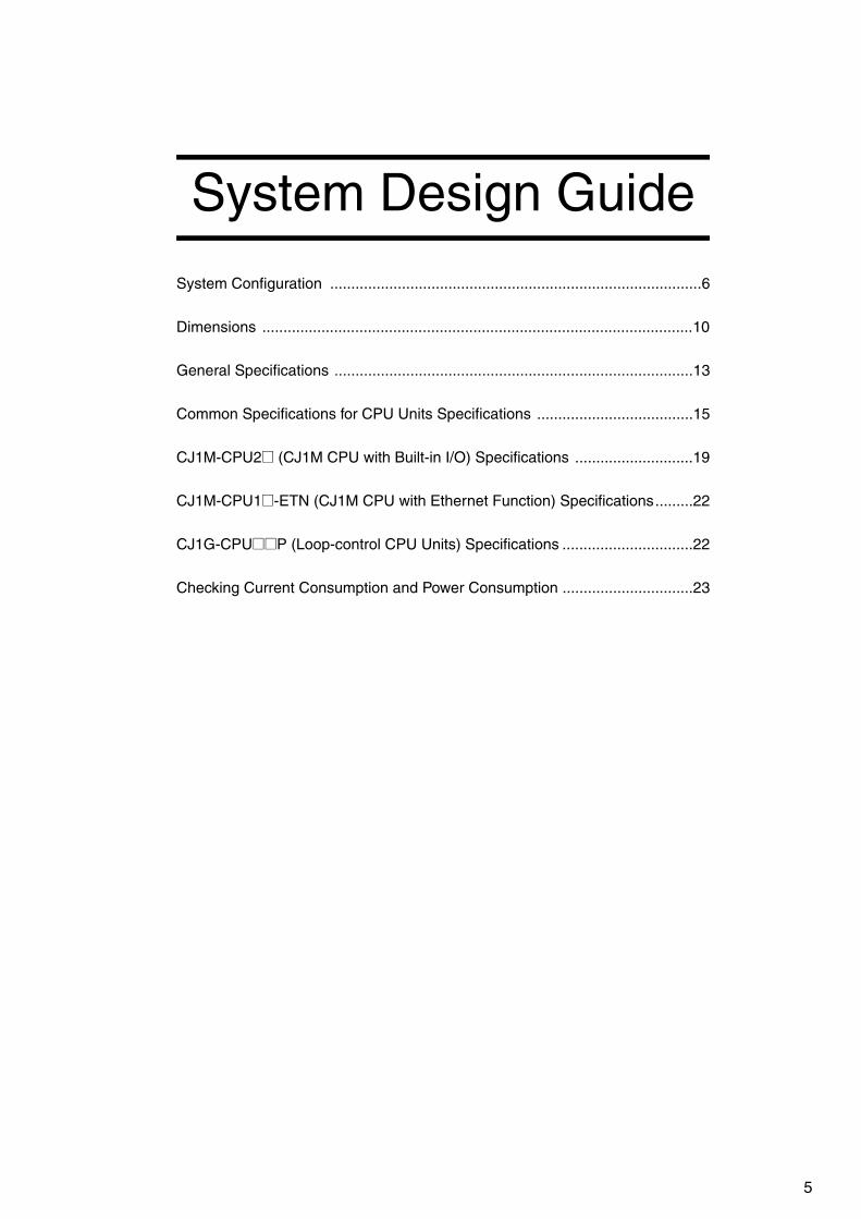
5
System Design Guide
System Configuration ........................................................................................6
Dimensions ......................................................................................................10
General Specifications .....................................................................................13
Common Specifications for CPU Units Specifications .....................................15
CJ1M-CPU2@ (CJ1M CPU with Built-in I/O) Specifications ............................19
CJ1M-CPU1@-ETN (CJ1M CPU with Ethernet Function) Specifications.........22
CJ1G-CPU@@P (Loop-control CPU Units) Specifications ...............................22
Checking Current Consumption and Power Consumption ...............................23

6 Programmable Controllers CJ1
System Configuration
■ Basic System
POWER
PA205R
DC24VAC240V
OUTPUTRUN
INPUTAC100-240V
L2/N
L1
CONTROLLER
CJ1G-CPU44SYSMAC
PROGRAMMABLEERR/ALM
RUN
COMM
INHPRPHL
OPEN
PERIPHERAL
BUSY
MCPWR
PORT
CPU Rack (Backplane-free Structure)
Expansion Rack (Backplane-free Structure)
Memory Card
HMC-EF183
Peripheral Port Cable
Personal Computer CableCS1W-CN226/626
Programming Devices
CX-One (e.g., CX-Programmer)Programming Console
RS-232C Cable for PT
XW2Z-200T/500T
RS-232C Cable for Personal Computer
XW2Z-200S/500S-CV
RS-422A Adapter
CJ1W-CIF11
CS1 Expansion Cables
CS1W-CN@@3(30 cm, 70 cm, 2 m, 3 m,
5 m, 10 m, 12 m)
Programmable Terminal (PT)
NS Series
CJ1 Basic I/O UnitsCJ1 Special I/O UnitsCJ1 CPU Bus UnitsNote: A maximum of 10 Units can be mounted.
CJ1 Power Supply Units
CJ1W-PA205CCJ1W-PA205RCJ1W-PA202CJ1W-PD025CJ1W-PD022
CJ1 CPU Units
CJ1M-CPU1@CJ1M-CPU2@CJ1M-CPU1@-ETN CJ1G-CPU4@P (-GTC)
CJ1 I/O Control Unit
CJ1W-IC101
CJ1 End Cover
CJ1W-TER01
CJ1 I/O Interface Unit
CJ1W-II101

Programmable Controllers CJ1 7
■ Configuration Units
Note: Windows is a registered trademark of Microsoft Corporation in the United States and other countries.Microsoft product screen shots reprinted with permission from Microsoft Corporarion.Other company names and product names in this document are the trademarks or registered trademarks of their respective companies.
CJ1 Basic I/O Units
8-point Units 16-point Units 32-point Units 64-point Units
Input Units● DC Input UnitCJ1W-ID201● AC Input UnitCJ1W-IA201
● DC Input UnitCJ1W-ID211CJ1W-ID212 ● AC Input UnitCJ1W-IA111
● DC Input UnitCJ1W-ID231CJ1W-ID232CJ1W-ID233
● DC Input UnitCJ1W-ID261CJ1W-ID262
Output Units● Relay Contact Output Unit
(independent commons) CJ1W-OC201● Triac Output UnitCJ1W-OA201● Transistor Output UnitsCJ1W-OD201CJ1W-OD202CJ1W-OD203CJ1W-OD204
● Relay Contact Output UnitCJ1W-OC211● Transistor Output UnitsCJ1W-OD211CJ1W-OD213 CJ1W-OD212
● Transistor Output UnitsCJ1W-OD231CJ1W-OD233CJ1W-OD234 CJ1W-OD232
● Transistor Output UnitsCJ1W-OD261CJ1W-OD263CJ1W-OD262
I/O Units
--- ---
(16 inputs, 16 outputs)● DC Input/Transistor Output UnitsCJ1W-MD231CJ1W-MD233CJ1W-MD232
32 inputs, 32 outputs● DC Input/Transistor Output UnitsCJ1W-MD261CJ1W-MD26332 inputs, 32 outputs● TTL I/O UnitCJ1W-MD563
Other Units
---
● Interrupt Input UnitCJ1W-INT01
---
● B7A Interface Units(64 inputs)CJ1W-B7A14
(64 outputs)CJ1W-B7A04
(32 inputs, 32 outputs)CJ1W-B7A22
● High-speed Input UnitCJ1W-IDP01
CJ1 Special I/O Units and CPU Bus Units■ Process I/O Units● Isolated-type Units with Universal
InputsCJ1W-PH41U
CJ1W-AD04U ● Isolated-type Thermocouple Input
UnitsCJ1W-PTS15CJ1W-PTS51● Isolated-type Resistance
Thermometer Input UnitsCJ1W-PTS16CJ1W-PTS52● Isolated-type DC Input UnitCJ1W-PDC15
■ Analog I/O Units● Analog Input UnitsCJ1W-AD042 CJ1W-AD081-V1CJ1W-AD041-V1● Analog Output UnitsCJ1W-DA042V CJ1W-DA08VCJ1W-DA08CCJ1W-DA041CJ1W-DA021● Analog I/O UnitsCJ1W-MAD42
■ Temperature Control UnitsCJ1W-TC001, CJ1W-TC002CJ1W-TC003, CJ1W-TC004CJ1W-TC101, CJ1W-TC102CJ1W-TC103, CJ1W-TC104
■ High-speed Counter UnitsCJ1W-CT021
■ Position Control UnitsCJ1W-NC214 CJ1W-NC414 CJ1W-NC234 CJ1W-NC434 CJ1W-NC113CJ1W-NC213CJ1W-NC413CJ1W-NC133CJ1W-NC233CJ1W-NC433
■ Position Control Unit with EtherCAT interface
CJ1W-NC281 CJ1W-NC481 CJ1W-NC881 CJ1W-NCF81 CJ1W-NC482 CJ1W-NC882
■ Position Control Unit with MECHATROLINK-II interface
CJ1W-NC271CJ1W-NC471CJ1W-NCF71CJ1W-NCF71-MA
■ Motion Control Unit with MECHATROLINK-II interface
CJ1W-MCH71
■ Serial Communications UnitsCJ1W-SCU22 CJ1W-SCU32 CJ1W-SCU42 CJ1W-SCU21-V1CJ1W-SCU31-V1CJ1W-SCU41-V1
■ EtherNet/IP UnitCJ1W-EIP21
■ Ethernet UnitCJ1W-ETN21
■ Controller Link UnitsCJ1W-CLK23
■ FL-net UnitCJ1W-FLN22
■ DeviceNet UnitCJ1W-DRM21
■ CompoNet Master UnitCJ1W-CRM21
■ CompoBus/S Master UnitCJ1W-SRM21
■ ID Sensor UnitsCJ1W-V680C11
CJ1W-V680C12
CJ1W-V600C11
CJ1W-V600C12
■ High-speed Data Storage UnitCJ1W-SPU01-V2
High-speed type
High-speed type
High-speed type
High-speed type
High-speed type
High-speed type
High-speed type
High-speed type
High-speed type
High-speed type
High-speed type
High-speed type
High-speed type

8 Programmable Controllers CJ1
■ CJ-series CPU RacksA CJ-series CPU Rack consists of a CPU Unit, Power Supply Unit, Configuration Units (Basic I/O Units, Special I/O Units, and CPU Bus
Units), and an End Cover.
● Required Units
● Types of UnitsIn the CJ Series, Units are classified into the following three types. The number of Racks differs depending on the type.
Note: CJ1M-CPU1@-ETN: A Maximum of 15 Units can be mounted. (The built-in Ethernet port on the CPU Unit must be allocated as one of the CPU Bus Units)
Rack Unit name Required number of Units
CPU Rack
Power Supply Unit 1
CPU Unit 1
I/O Control Unit Required only for mounting to an Expansion Rack.
Number of Configuration Units10 max. (Same for all models of CPU Unit.)(The number of Basic I/O Units, Special I/O Units, and CPU Bus Units can be varied. The number does not include the I/O Control Unit.)
End Cover 1 (Included with CPU Unit.)
Type Appearance (example) Description Unit recognition method No. of Units
Basic I/O Units Basic I/O Units with contact inputs and contactoutputs.
Recognized by the CPU Unit accord-ing to the position of the Rack and slot.
No restrictions.
Special I/O Units
Special I/O Units provide more advanced func-tions than do Basic I/O Units, including I/O otherthan contact inputs and contact outputs.Examples of Special I/O Units are Analog I/OUnits and High-speed Counter Units. They differfrom CPU Bus Units (including Network Communi-cations Units) in having a smaller area forexchanging data with the CPU Unit.
Recognized by the CPU Unit accord-ing to the unit number (0 to 95) set with the rotary switches on the front panel.
A maximum of 96 Units can be connected. (Multi-ple unit numbers are allo-cated per Unit, depending on the model and settings.)
CPU Bus Units CPU Bus Units exchange data with the CPU Unit via the CPU Bus.Examples of CPU Bus Units are Network Commu-nications Units and Serial Communications Units. They differ from Special I/O Units in having a larger area for exchanging data with the CPU Unit.
Recognized by the CPU Unit accord-ing to the unit number (0 to F) set with the rotary switch on the front panel.
A maximum of 16 Units can be mounted.(See note.)
POWER
PA205R
DC24VAC240V
OUTPUTRUN
INPUTAC100-240V
L2/N
L1
CONTROLLER
CJ1G-CPU44SYSMAC
PROGRAMMABLEERR/ALM
RUN
COMM
INHPRPHL
OPEN
PERIPHERAL
BUSY
MCPWR
PORT
CPU Rack
End CoverCJ1W-TER01(One End Cover is provided as a standard accessory with the CPU Unit.)
Power Supply UnitCJ1W-P@@@ (@)
CPU UnitCJ1@-CPU@@ (@)
I/O Control UnitCJ1W-IC101(Required only when connecting to an Expansion Rack.)
CJ-series Basic I/O UnitsCJ-series Special I/O UnitsCJ-series CPU Bus Units
Total: 10 Units max

Programmable Controllers CJ1 9
■ CJ-series Expansion RacksA CJ-series Expansion Rack consists of a Power Supply Unit, an I/O Interface Unit, Configuration Units (Basic I/O Units, Special I/O
Units, and CPU Bus Units), and an End Cover.
● Required Units
Note 1. Mounting the I/O Control Unit in any other location may cause faulty operation.2. Mounting the I/O Interface Unit in any other location may cause faulty operation.
● Maximum Number of Configuration Units That Can Be Mounted
Note: Up to nine Units can be connected to a CJ1M-CPU1@-ETN CPU Units. The maximum number of Configuration Units that can be connected is thus reduced by 1.
Rack Unit name Required number of Units
CPU Rack I/O Control Unit One Unit. Required only when an Expansion Rack is used. Mount the I/O Control Unit immediately to the right of the CPU Unit. (See note 1.)
Expansion Rack
Power Supply Unit One Unit
I/O Interface Unit One Unit. Mount the I/O Interface Unit immediately to the right of the Power Supply Unit. (See note 2.)
Number of Configuration Units Ten Units max. (The number of Basic I/O Units, Special I/O Units, and CPU Bus Units can be varied.This number does not include the I/O Interface Unit.)
End Cover One (Included with the I/O Interface Unit.)
CPU Unit Model Total Units No. of Units on CPU Rack No. of Expansion Racks
CJ1G CJ1G-CPU45P (-GTC) 40 10 per Rack 3 Racks x 10 Units
CJ1G-CPU44P
CJ1G-CPU43P 30 10 per Rack 2 Racks x 10 Units
CJ1G-CPU42P
CJ1M CJ1M-CPU13 (-ETN) 20 10 per Rack (See note.) 1 Rack x 10 Units
CJ1M-CPU23
CJ1M-CPU12 (-ETN) 10 10 per Rack (See note.) Cannot be connected.
CJ1M-CPU11 (-ETN)
CJ1M-CPU22
CJ1M-CPU21
Power Supply UnitCJ1W-P@@@(@)
CPU UnitCJ1@-CPU@@@(@)
I/O Control UnitCJ1W-IC101
I/O Interface UnitCJ1W-II101
Power Supply UnitCJ1W-P@@@(@)
CPU Rack
Expansion Rack
Expansion Rack
Number of Expansion Racks: None, 1, 2, or 3 (Depends on CPU Unit model.)
I/O Connecting CableCS1W-CN@@3
Configuration Units: 10 max.
I/O Interface UnitCJ1W-II101
CJ1W-P@@@(@)Power Supply Unit
CJ1W-II101I/O Interface Unit
CJ1W-P@@@(@)Power Supply Unit
I/O Connecting CableCS1W-CN@@3
I/O Connecting Cable CS1W-CN@@3
Expansion Rack
Totalcablelength≤ 12 m
Configuration Units: 10 max.
Configuration Units: 10 max.
Configuration Units: 10 max.

10 Programmable Controllers CJ1
Dimensions
Note: Units are in mm unless specified otherwise.
■ Product Dimensions
Power Supply Units, CPU Units, and End Covers
CPU Units
35.4
27
27.6
65
90
W
Example Rack Widths using CJ1WPA202 Power Supply Unit (AC, 14 W)No. of Units mounted with 31-mm width
Rack width (mm)
With CJ1M-CPU11/12/13
With CJ1M-CPU21/22/23
With CJ1M-CPU1@-ETN
With CJ1G-CPU4@P(-GTC) CPU Unit
1 121.7 139.7 152.7 159.7
2 152.7 170.7 183.7 190.7
3 183.7 201.7 214.7 221.7
4 214.7 232.7 245.7 252.7
5 245.7 263.7 276.7 283.7
6 276.7 294.7 307.7 314.7
7 307.7 325.7 338.7 345.7
8 338.7 356.7 369.7 376.7
9 369.7 387.7 400.7 407.7
10 400.7 418.7 431.7 438.7
Unit/product Model Width
Power Supply Unit
CJ1W-PA205C 80
CJ1W-PA205R 80
CJ1W-PA202 45
CJ1W-PD025 60
CJ1W-PD022 27
CPU Unit
CJ1M-CPU1@ 31
CJ1M-CPU2@ 49
CJ1M-CPU1@-ETN 62
CJ1G-CPU4@P 69
End Cover CJ1W-TER01 14.7
6581.6
W
90
W=27: CJ1W-PD022W=45: CJ1W-PA202W=80: CJ1W-PA205R CJ1W-PA205CW=60: CJ1W-PD025
14.7
90
34
38.8
�RS-422A Adapter CJ1W-CIF11
�Power Supply Units �End Cover (included with CPU Units)
CJ1G-CPU4@P CJ1M-CPU1@ CJ1M-CPU1@-ETN CJ1M-CPU2@
CONTROLLER
CJ1G-CPU44PSYSMAC
PROGRAMMABLEERR/ALM
RUN
COMM
INHPRPHL
OPEN
PERIPHERAL
BUSY
MCPWR
PORT
LCB03 EXECRDY
INNER LOOP CONTROLLER
90
2.7
2.7
6973.9
65 6573.9
90
2.7
2.7
31 656273.9
90
2.7
2.731
90
2.7
2.7
654983.6
83.7

Programmable Controllers CJ1 11
● Units of Width 20 mm
● I/O Control Unit ● 32-Point I/O Units (CJ1W-ID223@/OD23@)
● Units of Width 31 mm
● 64-point Basic I/O Units and 32-point Basic I/O Units (CJ1W-MD23@)
● Special I/O Units and CPU Bus Units
Unit/product Model Width
I/O Control Unit CJ1W-IC101
20
32-point Basic I/O UnitsCJ1W-ID231/232/233
CJ1W-OD231/232/233/234
B7A Interface UnitCJ1W-B7A22CJ1W-B7A14CJ1W-B7A04
CompoBus/S Master Unit CJ1W-SRM21
Space Unit CJ1W-SP001
90
2.7
2.7(140)
6569.3
68
20 65
90
2.7
2.7
2066.5
6583.6
Fujitsu connector MIL connector
(112.5)
Unit Model WidthI/O Interface Unit CJ1W-II101
31
8/16-point Basic I/O Units
CJ1W-ID201CJ1W-ID211/212CJ1W-IA111/201CJ1W-OD20@CJ1W-OD211/212/213CJ1W-OC201/211CJ1W-OA201
32-point Basic I/O UnitsCJ1W-MD231CJ1W-MD232/233
64-point Basic I/O Units
CJ1W-ID261CJ1W-OD261CJ1W-MD261
CJ1W-ID262CJ1W-OD262/263CJ1W-MD263CJ1W-MD563
Interrupt Input Unit CJ1W-INT01
High-speed Input Unit CJ1W-IDP01
Analog I/O UnitsCJ1W-AD@@@(-V1)CJ1W-DA@@@(@)CJ1W-MAD42
Process Input Units
CJ1W-PH41UCJ1W-AD04UCJ1W-PTS51/52/15/16CJ1W-PDC15
Temperature Control Units CJ1W-TC@@@
Position Control UnitsCJ1W-NC113/133CJ1W-NC213/233CJ1W-NC413/433
Unit Model Width
Position Control Units with EtherCAT interface
CJ1W-NC281CJ1W-NC481CJ1W-NC881CJ1W-NCF81CJ1W-NC482CJ1W-NC882
31
Position Control Unit with MECHATROLINK-II interface
CJ1W-NC271CJ1W-NC471CJ1W-NCF71CJ1W-NCF71-MA
High-speed Counter Unit CJ1W-CT021
ID Sensor Units
CJ1W-V680C11CJ1W-V680C12CJ1W-V600C11CJ1W-V600C12
Controller Link Units CJ1W-CLK23
Serial Communications Units
CJ1W-SCU22CJ1W-SCU32CJ1W-SCU42CJ1W-SCU41-V1CJ1W-SCU21-V1CJ1W-SCU31-V1
EtherNet/IP Unit CJ1W-EIP21
Ethernet Unit CJ1W-ETN21
DeviceNet Unit CJ1W-DRM21
CompoNet Master Unit CJ1W-CRM21
FL-net Unit CJ1W-FLN22
(140)68
90
2.7
2.7
653169.3
90
2.7
2.7
31 6589
● I/O Interface Unit ● 8/6-point Basic I/O Units,Interrupt Input Unit, and High-speed Input Unit
(112.5)
MIL connector
6566.5
90
2.7
2.7
31
Fujitsu connector
6583.6
90
2.7
2.7
31

12 Programmable Controllers CJ1
● Unit of Width 51 mm
● SPU Unit (High-speed Data Storage Unit)CJ1W-SPU01-V2
● Unit of Width 79.8 mm
● Motion Control Unit with MECHATROLINK-II interfaceCJ1W-MCH71
● Unit of Width 62 mm
● Position Contorl Unit (High-speed model)CJ1W-NC414/434
■ Mounting Dimensions ■ Mounting HeightThe mounting height of CJ-series CPU Racks and ExpansionRacks is from 81.6 to 89.0 mm depending on the Units that aremounted.Additional height is required to connect Programming Devices(e.g., CX-Programmer or Programming Console) and Cables. Besure to allow sufficient mounting height.
Note: Consider the following points when expanding the configuration:The total length of I/O Connecting Cable must not exceed 12 m.I/O Connecting Cables require the bending radius indicated below.
● CJ-series Connecting Cable
Unit Model Width
SPU Unit(High-speed Data Storage Unit)
CJ1W-SPU01-V251
Position Control Units(High-speed type)
CJ1W-NC214/234
Unit Model Width
Motion Control Unit with MECHATROLINK-II interface
CJ1W-MCH71 79.8
6551 9
2.7
90
2.7
90
79.8 6570.9
Unit Model Width
Position Control Units(High-speed type)
CJ1W-NC414/434 62
62
6584
2.7
90
2.7
90
A65
35
27.5
27.5
DIN Track model number A
PFP-100N2 16 mm
PFP-100N 7.3 mm
FPP-50N 7.3 mm
81.6 to 89.0 mm
Approx. 100 to 150 mm
R R ≥ 69 mm
Note: Outer diameter of cable: 8.6 mm.

Programmable Controllers CJ1 13
General Specifications
Item Specifications
Power Supply Unit CJ1W-PA205R CJ1W-PA205C CJ1W-PA202 CJ1W-PD025 CJ1W-PD022
Supply voltage 100 to 240 V AC (wide-range), 50/60 Hz 24 VDC
Operating voltage and frequency ranges
85 to 264 V AC, 47 to 63 Hz 19.2 to 28.8 V DC 21.6 to 26.4 V DC
Power consumption 100 VA max. 50 VA max. 50 W max. 35 W max.
Inrush current(See note 1.)
At 100 to 120 V AC:15 A/8 ms max. for cold start at room temperatureAt 200 to 240 V AC:30 A/8 ms max. for cold start at room temperature
At 100 to 120 V AC:20 A/8 ms max. for cold start at room temperatureAt 200 to 240 V AC:40 A/8 ms max. for cold start at room temperature
At 24 V DC:30 A/20 ms max. for cold start at room temperature
Output capacity (See note 7.)
5.0 A, 5 V DC (including supply to CPU Unit)2.8 A, 5 V DC(including supply to CPU Unit)
5.0 A, 5 V DC(including supply to CPU Unit)
2.0 A, 5 V DC(including supply to CPU Unit)
0.8 A, 24 V DC 0.4 A, 24 V DC 0.8 A, 24 V DC 0.4 A, 24 V DC
Total: 25 W max. Total: 14 W max. Total: 25 W max. Total: 19.6 W max.
Output terminal (service supply)
Not provided.
RUN output (See note 2.)
Contact configuration:SPST-NOSwitch capacity:250 V AC, 2 A (resistive load)120 V AC, 0.5 A(inductive load), 24 V DC, 2A (resistive load)24 V DC, 2 A (inductive load)
Not provided.
Replacement notifica-tion function
Not provided.With Alarm output (open-collector output)30 V DC max., 50 mA max.
Not provided.
Insulation resistance
20 MΩ min. (at 500 V DC) between AC external and GR terminals(See note 3.)
• 20 MΩ min. (at 500 V DC) between all external terminals and GR terminal (See note 3.), and between all alarm output terminals.
• 20 MΩ 1 min. (at 250 V DC) between all alarm output terminals and GR terminal (See note 3.).
20 MΩ min. (at 500 V DC) between AC external and GR terminals(See note 3.)
20 MΩ min. (at 500 V DC) between DC external and GR terminals (See note 3.)
---(See note 6.)
Dielectric strength (See note 4.)
2,300 V AC 50/60 Hzfor 1 min between AC external and GR terminals (See note 3.)Leakage current: 10 mA max.
• 2,300 VAC, 50/60 Hz for 1 minute between all external terminals and GR terminal (See note 3.) and between all alarm output terminals with a leakage current of 10 mA max.
• 1,000 V AC, 50/60 Hz for 1 minute between all alarm output terminals and GR terminal (See note 3.) with a leakage current of 10 mA max.
2,300 V AC 50/60 Hzfor 1 min between AC external and GR terminals (See not 3.)Leakage current: 10 mA max.
1,000 V AC, 50/60 Hz for 1 minute between DC external and GR terminals (See note 3.)Leakage current: 10 mA max.
---(See note 6.)
1,000 V AC, 50/60 Hz for 1 minute between DC external and GR terminals (See note 3.)Leakage current: 10 mA max.
Noise immunity 2 kV on power supply line (conforming to IEC61000-4-4)
Vibration ResistanceConforms to IEC60068-2-65 to 8.4 Hz with 3.5-mm amplitude, 8.4 to 150 HzAcceleration of 9.8 m/s2 for 100 min in X, Y, and Z directions (10 sweeps of 10 min each = 100 min total)
Shock ResistanceConforms to IEC60068-2-27147 m/s2, 3 times in X, Y, and Z directions (100 m/s2 for Relay Output Units)
Ambient operating temperature
0 to 55°C
Ambient operating humidity
10% to 90% (with no condensation)
10% to 90% (with no condensation)(See note 5.)
10% to 90% (with no condensation)
Atmosphere Must be free from corrosive gases.
Ambient storage temperature
−20 to 70°C (excluding battery)
−20 to 75°C (See note 5.) −20 to 75°C (excluding battery)
Grounding Less than 100 ΩEnclosure Mounted in a panel.
Weight All models are each 5 kg max.

14 Programmable Controllers CJ1
Note 1. Disconnect the Power Supply Units LG terminal from the GR terminal when testing insulation and dielectric strength. Testing the insulation and dielectric strength with the LG terminal and the GR terminals connected will damage internal circuits in the CPU Unit.
2. Supported only when mounted to CPU Rack.3. The inrush current is given for a cold start at room temperature. The inrush control circuit uses a thermistor element with a low-temperature current control
characteristic. If the ambient temperature is high or the PLC is hot-started, the thermistor will not be sufficiently cool, and the inrush currents given in the table may be exceeded by up to twice the given values. When selecting fuses or breakers for external circuits, allow sufficient margin in shut-off performance.
4. Maintain an ambient storage temperature of −25 to 30°C and relative humidity of 25% to 70% when storing the Unit for longer than 3 months to keep the re-placement notification function in optimum working condition.
5. Change the applied voltage gradually using the adjuster on the Tester. If the full dielectric strength voltage is applied or turned OFF using the switch on the Tester, the generated impulse voltage may damage the Power Supply Unit.
6. CJ1W-PD022 is not insulated between the primary DC power and secondary DC power.7. Internal components in the Power Supply Unit will deteriorate or be damaged if the Power Supply Unit is used for an extended period of time exceeding the
power supply output capacity or if the outputs are shorted.
CPU Rack dimensions
90.7 to 466.7 × 90 × 65 mm (W × H × D) (not including cables)Note: W = a + b + 20 × n + 31 × m + 14.7
a: Power Supply Unit: PA205R and PA205C = 80; PA202 = 45; PD025 = 60; PD022=27b: CPU Unit: CJ1-H or CJ1 = 62; CJ1M-CPU1@ = 31; CJ1M-CPU1@-ETN = 62; CJ1M-CPU2@ = 49The total width is given by the following: W = 156.7 + n × 20 + m × 31, where n is the number of 32-point I/O Units or I/O Control Units and m is the number of other Units.
Safety measures Conforms to cULus and EC Directives.
Item Specifications
Power Supply Unit CJ1W-PA205R CJ1W-PA205C CJ1W-PA202 CJ1W-PD025 CJ1W-PD022

Programmable Controllers CJ1 15
Specifications
■ Common SpecificationsItem Specifications
Control method Stored program
I/O control method Cyclic scan and immediate processing are both possible.
Programming Languages Ladder Logic (LD), Sequential Function Charts (SFC), Structured Text (ST), and Mnemonic.
CPU processing modeCJ1M CPU Units: Normal Mode or Peripheral Servicing Priority ModeCJ1 CPU Units: Normal Mode or Peripheral Servicing Priority Mode
Instruction length 1 to 7 steps per instruction
Ladder instructions Approx. 400 (3-digit function codes)
Execution time
Basic instructionsCJ1M CPU Units (CPU12(-ETN)/13(-ETN)/22/23): CJ1M CPU Units (CPU11(-ETN)/21): CJ1 CPU Units:
0.10 μs min.0.10 μs min.0.08 μs min.
Special instructions
CJ1M CPU Units (CPU12(-ETN)/13(-ETN)/22/23): CJ1M CPU Units (CPU11(-ETN)/21): CJ1 CPU Units:
0.15 μs min.0.15 μs min.0.12 μs min.
Overhead timeCJ1M CPU Units (CPU12(-ETN)/13(-ETN)/22/23): CJ1M CPU Units (CPU11(-ETN)/21): CJ1 CPU Units:
0.5 ms min.0.7 ms min.0.5 ms min.
Unit connection method No Backplane: Units connected directly to each other.
Mounting method DIN Track (screw mounting not possible)
Maximum number of connectable Units
• CJ1M CPU Units:Total of 20 Units in the System, including 10 Units on CPU Rack and 10 Units on one Expansion Rack.
• CJ1M CPU Units (CPU1@-ETN):Total of 19 Units, including 9 Units on CPU Rack and 10 Units on one Expansion Rack. (The built-in Ethernet port on the CPU Unit must be allocated to a slots 0, and is counted as one Unit.
Maximum number of Expansion Racks
• CJ1 CPU Units: 3 max. (An I/O Control Unit is required on the CPU Rack and an I/O Interface Unit is required on each Expansion Rack.)
• CJ1M CPU Units (CPU 13(-ETN)/23 only): 1 max. (An I/O Control Unit is required on the CPU Rack and an I/O Interface Unit is required on the Expansion Rack.)
• CJ1M CPU Units (CPU11(-ETN)/12(-ETN)/21/22): Expansion is not possible.
Number of tasks
288 (cyclic tasks: 32, interrupt tasks: 256)With CJ1M CPU Units, interrupt tasks can be defined as cyclic tasks called extra cyclic tasks. Including these, up to 288 cyclic tasks can be used.Note 1. Cyclic tasks are executed each cycle and are controlled with TKON(820) and TKOF(821) instructions.
2. The following 4 types of interrupt tasks are supported.Power OFF interrupt tasks: 1 max.Scheduled interrupt tasks: 2 max.I/O interrupt tasks: 32 max.External interrupt tasks: 256 max.
Interrupt types
Scheduled Interrupts: Interrupts generated at a time scheduled by the CPU Units built-in timer. (See note. 1)I/O Interrupts: Interrupts from Interrupt Input Units.Power OFF Interrupts (See note 2.): Interrupts executed when the CPU Units power is turned OFF.External I/O Interrupts: Interrupts from the Special I/O Units or CPU Bus Units.Note 1. CJ1 CPU Units: Scheduled interrupt time interval is either 1 ms to 9,999 ms or 10 ms to 99,990 ms, in units of 1 ms
or 10 ms. CJ1M CPU Units: In addition to the above, a scheduled interrupt time interval of 0.5 ms to 999.9 ms, in units of 0.1ms, is also possible.
2. Not supported when the CJ1W-PD022 Power Supply Unit is mounted.
CIO (Core I/O) Area
I/O Area
2,560: CIO 000000 to CIO 015915 (160 words from CIO 0000 to CIO 0159)The setting of the first word can be changed from the default (CIO 0000) so that CIO 0000 to CIO 0999 can be used.I/O bits are allocated to Basic I/O Units.
The CIO Area can be used as work bits if the bits are not used as shown here.
Link Area3,200 (200 words): CIO 10000 to CIO 119915 (words CIO 1000 to CIO 1199)Link bits are used for data links and are allocated to Units in Controller Link Systems.
CPU Bus Unit Area 6,400 (400 words): CIO 150000 to CIO 189915 (words CIO 1500 to CIO 1899)CPU Bus Unit bits store the operating status of CPU Bus Units. (25 words per Unit, 16 Units max.)
Special I/O Unit Area
15,360 (960 words): CIO 200000 to CIO 295915 (words CIO 2000 to CIO 2959)Special I/O Unit bits are allocated to Special I/O Units. (10 words per Unit, 96 Units max.)
Serial PLC Link Area (CJ1M CPU Units only)
1,440 (90 words): CIO 310000 to CIO 318915 (words CIO 3100 to CIO 3189)
16 Programmable Controllers CJ1
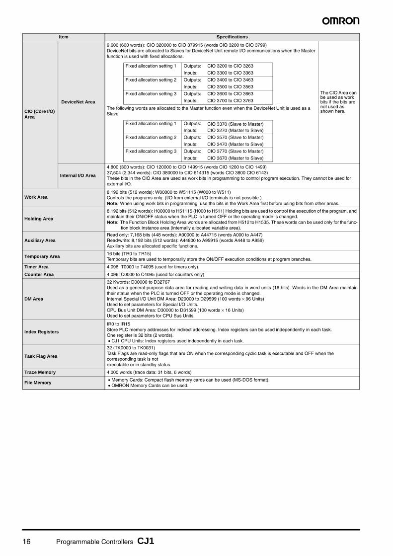
CIO (Core I/O) Area
DeviceNet Area
9,600 (600 words): CIO 320000 to CIO 379915 (words CIO 3200 to CIO 3799)DeviceNet bits are allocated to Slaves for DeviceNet Unit remote I/O communications when the Master function is used with fixed allocations.
The following words are allocated to the Master function even when the DeviceNet Unit is used as a Slave.
The CIO Area can be used as work bits if the bits are not used as shown here.
Internal I/O Area
4,800 (300 words): CIO 120000 to CIO 149915 (words CIO 1200 to CIO 1499)37,504 (2,344 words): CIO 380000 to CIO 614315 (words CIO 3800 CIO 6143)These bits in the CIO Area are used as work bits in programming to control program execution. They cannot be used for external I/O.
Work Area8,192 bits (512 words): W00000 to W51115 (W000 to W511)Controls the programs only. (I/O from external I/O terminals is not possible.)Note: When using work bits in programming, use the bits in the Work Area first before using bits from other areas.
Holding Area
8,192 bits (512 words): H00000 to H51115 (H000 to H511) Holding bits are used to control the execution of the program, and maintain their ON/OFF status when the PLC is turned OFF or the operating mode is changed.Note: The Function Block Holding Area words are allocated from H512 to H1535. These words can be used only for the func-
tion block instance area (internally allocated variable area).
Auxiliary AreaRead only: 7,168 bits (448 words): A00000 to A44715 (words A000 to A447)Read/write: 8,192 bits (512 words): A44800 to A95915 (words A448 to A959)Auxiliary bits are allocated specific functions.
Temporary Area16 bits (TR0 to TR15)Temporary bits are used to temporarily store the ON/OFF execution conditions at program branches.
Timer Area 4,096: T0000 to T4095 (used for timers only)
Counter Area 4,096: C0000 to C4095 (used for counters only)
DM Area
32 Kwords: D00000 to D32767Used as a general-purpose data area for reading and writing data in word units (16 bits). Words in the DM Area maintaintheir status when the PLC is turned OFF or the operating mode is changed.Internal Special I/O Unit DM Area: D20000 to D29599 (100 words × 96 Units)Used to set parameters for Special I/O Units.CPU Bus Unit DM Area: D30000 to D31599 (100 words × 16 Units) Used to set parameters for CPU Bus Units.
Index Registers
IR0 to IR15Store PLC memory addresses for indirect addressing. Index registers can be used independently in each task. One register is 32 bits (2 words).• CJ1 CPU Units: Index registers used independently in each task.
Task Flag Area
32 (TK0000 to TK0031)Task Flags are read-only flags that are ON when the corresponding cyclic task is executable and OFF when the corresponding task is notexecutable or in standby status.
Trace Memory 4,000 words (trace data: 31 bits, 6 words)
File Memory• Memory Cards: Compact flash memory cards can be used (MS-DOS format).• OMRON Memory Cards can be used.
Item Specifications
Fixed allocation setting 1 Outputs: CIO 3200 to CIO 3263
Inputs: CIO 3300 to CIO 3363
Fixed allocation setting 2 Outputs: CIO 3400 to CIO 3463
Inputs: CIO 3500 to CIO 3563
Fixed allocation setting 3 Outputs: CIO 3600 to CIO 3663
Inputs: CIO 3700 to CIO 3763
Fixed allocation setting 1 Outputs: CIO 3370 (Slave to Master)Inputs: CIO 3270 (Master to Slave)
Fixed allocation setting 2 Outputs: CIO 3570 (Slave to Master)
Inputs: CIO 3470 (Master to Slave)
Fixed allocation setting 3 Outputs: CIO 3770 (Slave to Master)
Inputs: CIO 3670 (Master to Slave)

Programmable Controllers CJ1 17
■ Function SpecificationsItem Specifications
Constant cycle time 1 to 32,000 ms (Unit: 1 ms)
Cycle time monitoring Possible (Unit stops operating if the cycle is too long): 10 to 40,000 ms (Unit: 10 ms)
I/O refreshingCyclic refreshing, immediate refreshing, refreshing by IORF(097).Note: ORF(097) refreshes I/O bits allocated to Basic I/O Units and Special I/O Units. With the CJ1M CPU Units, the CPU BUS UNIT I/O
REFRESH (DLNK(226)) instruction can be used to refresh bits allocated to CPU Bus Units in the CIO and DM Areas.
Timing of special refreshing for CPU Bus Units
Data links for Controller Link Units and SYSMAC LINK Units, remote I/O for DeviceNet Units, and other special refreshing for CPU Bus Units is performed at the following times:• CJ1 and CJ1M CPU Units: I/O refresh period
I/O memory holding when changing operating modes
Depends on the ON/OFF status of the IOM Hold Bit in the Auxiliary Area.
Load OFF All outputs on Output Units can be turned OFF when the CPU Unit is operating in RUN, MONITOR, or PROGRAM mode.
Timer/Counter PV refresh method
CJ1M CPU Units: BCD or binary (CX-Programmer Ver. 3.0 or higher).CJ1 CPU Units: BCD only.
Input response time setting
Time constants can be set for inputs from Basic I/O Units.The time constant can be increased to reduce the influence of noise and chattering or it can be decreased to detect shorter pulses on the inputs.
Mode setting at power-up
Possible.Note: By default, the CPU Unit will start in RUN mode if a Programming Console is not connected.
Flash memory
• The user program and parameter area data (e.g., PLC Setup) are always backed up automatically in flash memory. (automatic backupand restore.)
• CPU Units with unit version 3.0 or later only:When downloading projects from CX-Programmer Ver. 5.0 or higher, symbol table files (including CX-Programmer symbol names, I/O comments), comment files (CX-Programmer rung comments, other comments), and program index files (CX-Programmer section names, section comments, or program comments) are stored in comment memory within the flash memory.
Memory Card functions
Automatically reading programs (autoboot) from the Memory Card when the power is turned ON.
Possible.
Program replacement during PLC operation Possible.
Format in which data is stored in Memory CardUser program: Program file format PLC Setup and other parameters:Data file format I/O memory: Data file format (binary format), text format, or CSV format
Functions for which Memory Card read/write is supported
User program instructions, Programming Devices (including CX-Programmer and Programming Consoles), Host Link computers, AR Area control bits, easy backup operation
Filing Memory Card data and the EM (Extended Data Memory) Area can be handled as files.
DebuggingControl set/reset, differential monitoring, data tracing (scheduled, each cycle, or when instruction is executed), instruction error tracing, storing location generating error when a program error occurs.
Online editingUser programs can be overwritten in program-block units when the CPU Unit is in MONITOR or PROGRAM mode.This function is not available for block programming areas.With the CX-Programmer, more than one program block can be edited at the same time.
Program protectionOverwrite protection: Set using DIP switch.Copy protection: Password set using CX-Programmer or Programming Consoles.
Error checkUser-defined errors (i.e., user can define fatal errors and non-fatal errors)The FPD(269) instruction can be used to check the execution time and logic of each programming block.Note: FAL and FALS instructions can be used with the CJ1M CPU Units to simulate errors.
Error logUp to 20 errors are stored in the error log. Information includes the error code, error details, and the time the error occurred.Note: A CJ1M CPU Unit can be set so that user-defined FAL errors are not stored in the error log.
Serial communica-tions
Built-in peripheral port: Programming Device (including Programming Console) connections, Host Links, NT Links, Serial Gateway (CompoWay/F master)Built-in RS-232C port: Programming Device (excluding Programming Console) connections, Host Links, no-protocol communications, NT Links, Modbus-RTU Slave, Serial Gateway (CompoWay/F master or Modbus master)
Serial Communications Unit (sold separately): Protocol macros, Host Links, NT Links
Clock
Provided on all models.
Note: Used to store the time when power is turned ON and when errors occur.
Power OFF detection time
AC Power Supply Unit: 10 to 25 ms (not fixed)DC Power Supply Unit PD025: 2 to 5 ms; PD022: 2 to 10 ms
Power OFF detection delay time
0 to 10 ms (user-defined, default: 0 ms)Note: Not supported when the CJ1W-PD022 Power Supply Unit is mounted.
Memory protection
Held Areas: Holding bits, contents of Data Memory and Extended Data Memory, and status of the counter Completion Flags and present values.Note: If the IOM Hold Bit in the Auxiliary Area is turned ON, and the PLC Setup is set to maintain the IOM Hold Bit status when power to
the PLC is turned ON, the contents of the CIO Area, the Work Area, part of the Auxiliary Area, timer Completion Flag and PVs, IndexRegisters, and the Data Registers will be saved for up to 20 days.
Sending commands to a Host Link computer
FINS commands can be sent to a computer connected via the Host Link System by executing Network Communications Instructions from the PLC.
Remote program-ming and monitoring
Host Link communications can be used for remote programming and remote monitoring through a Controller Link System or Ethernet network.
Accuracy: Ambient temperature Monthly error
55°C −3.5 min to +0.5 min
25°C −1.5 min to +1.5 min
0°C −3 min to +1 min

18 Programmable Controllers CJ1
● Functions Added for New Unit VersionsRefer to the CJ-series CJ1 CPU Units Datasheet.
● Relations between CX-Programmer Versions and Unit Versions of CPU UnitsRefer to the CJ-series CJ1 CPU Units Datasheet.
Communicating across networklevels
Remote programming and monitoring from Support Software and FINS message communications can be performed across different network levels, even for different types of network.Pre-Ver. 2.0: Three levelsVersion 2.0 or later: Eight levels for Controller Link and Ethernet networks (See note.), three levels for other networks.Note: To communicate across eight levels, the CX-Integrator or the CX-Net in Programmer version 4.0 or higher must be used to set the
routing tables.
Storing comments in CPU Unit
I/O comments can be stored as symbol table files in the Memory Card, EM file memory, or comment memory (see note).Note: Comment memory is supported for CX-Programmer version 5.0 or higher and CS/CJ-series CPU Units with unit version 3.0 or later
only.
Program checkProgram checks are performed at the beginning of operation for items such as no END instruction and instruction errors.CX-Programmer can also be used to check programs.
Control output signals
RUN output: The internal contacts will turn ON (close) while the CPU Unit is operating (CJ1W-PA205R).
Battery life• Battery Set for CJ1 CPU Units: CPM2A-BAT01• Battery Set for CJ1M CPU Units: CJ1W-BAT01
Self-diagnostics CPU errors (watchdog timer), I/O bus errors, memory errors, and battery errors.
Other functions Storage of number of times power has been interrupted. (Stored in A514.)
Item Specifications

Programmable Controllers CJ1 19
CJ1M-CPU2@ (CJ1M CPU with Built-in I/O) Specifications
• CJ1M-CPU2@ CPU Units have 10 built-in inputs and 6 built-in outputs.
• The 10 inputs can be used as general-purpose inputs, interrupt inputs, quick-response inputs, high-speed counters, or origin search
origin input signals.
• The 6 outputs can be used as general-purpose outputs, pulse outputs, or origin search deviation counter reset outputs.
■ Data Area Allocations for Built-in I/O
Note: CJ1M-CPU21 CPU Units have one PWM output only and do not have PWM output 1.
■ Built-in Input Specifications● Interrupt Inputs and Quick-response Inputs
● High-speed Counter Inputs
I/O Code IN 0 IN 1 IN 2 IN 3 IN 4 IN 5 IN 6 IN 7 IN 8 IN 9 OUT 0 OUT 1 OUT 2 OUT 3 OUT 4 OUT 5
Address 2960 2961
Bit 0 1 2 3 4 5 6 7 8 9 0 1 2 3 4 5
Inputs
General purpose inputs
General purpose input 0
General purpose input 1
General purpose input 2
General purpose input 3
General pur-pose input 4
General pur-pose input 5
General pur-pose input 6
General pur-pose input 7
General pur-pose input 8
General pur-pose input 9
--- --- --- --- --- ---
Interrupt inputs Interrupt input 0
Interrupt input 1
Interrupt input 2
Interrupt input 3
--- --- --- --- --- --- --- --- --- --- --- ---
Quick response inputs
Quick response input 0
Quick response input 1
Quick response input 2
Quick response input 3
--- --- --- --- --- --- --- --- --- --- --- ---
High-speed counters --- ---
High-speed counter 1 (phase- Z/reset)
High-speed counter 0 (phase- Z/reset)
--- ---
High-speed counter 1 (phase-A, incre-ment, or count input)
High-speed counter 1 (phase-B, dec-rement, or direc-tion input)
High-speed counter 0 (phase-A, incre-ment, or count input)
High-speed counter 0 (phase-B, dec-rement, or direc-tion input)
--- --- --- --- --- ---
Out-puts
General-pur-pose outputs --- --- --- --- --- --- --- --- --- ---
Gen-eral-pur-pose output 0
Gen-eral- pur-pose output 1
Gen-eral-pur-pose output 2
Gen-eral-pur-pose output 3
Gen-eral-pur-pose output 4
Gen-eral-pur-pose output 5
Pulse out-puts
CW/CCW outputs --- --- --- --- --- --- --- --- --- ---
Pulse output 0 (CW)
Pulse output 0 (CCW)
Pulse output 1 (CW)
Pulse output 1 (CCW)
--- ---
Pulse + direction outputs
--- --- --- --- --- --- --- --- --- ---
Pulse output 0 pulse)
Pulse output 1 (pulse)
Pulse output 0 (direc-tion)
Pulse output 1 (direc-tion)
--- ---
Variable duty ratio outputs
--- --- --- --- --- --- --- --- --- --- --- --- --- ---
PWM(891) out-put 0
PWM(891) out-put 1
Origin search
Origin search 0 (Origin Input Signal)
Origin search 0 (Origin Proxim-ity Input Signal)
Origin search 1 (Origin Input Signal)
Origin search 1 (Origin Proxim-ity Input Signal)
Origin search 0 (Posi-tioning Com-pleted Signal)
Origin search 1 (Posi-tioning Com-pleted Signal)
--- --- --- --- --- --- --- ---
Origin search 0 (Error Counter Reset Output)
Origin search 1 (Error Counter Reset Output)
Item Specifications
No. of interrupt inputs/quick-response inputs
4 total
Input inter-rupts
Direct (Input Interrupt) Mode
Execution of an interrupt task is started at the interrupt input's rising or falling edge. Interrupt numbers 140 to 143 are used (fixed).Response time from meeting input condition to start of interrupt task execution: 93 μs min.
High-speed Counter Mode
Rising or falling edges of the interrupt are counted using either an incrementing or decrementing counter, and an interrupt task is started when the input count reaches the set value. Interrupt numbers 140 to 143 are used (fixed).I/O response frequency: 1 kHz
Quick-response inputsSignals that are shorted than the cycle time (30 μs min.) can be read and treated the same as signals that are one for more than one cycle time.
Item Specifications
Number of high-speed counters
2 (High-speed counters 0 and 1)
Pulse input mode (Selected in PLC Setup)
Differential phase inputs (phase-A, phase-B, and phase-Z input)
Up/down inputs (up inputs, down inputs, reset inputs)
Pulse + direction inputs (pulse inputs, direction inputs, reset inputs)
Increment inputs (increment inputs, reset inputs)
Re-sponse frequency
Line-driver inputs
50 kHz 100 kHz 100 kHz 100 kHz
24-V DC inputs 30 kHz 60 kHz 60 kHz 60 kHz
Counting mode Linear mode or Ring mode (Select in the PLC Setup.)

20 Programmable Controllers CJ1
■ Built-in Output Specifications● Position Control and Speed Control
● Variable-duty Pulse Outputs (PWM)
Note: CJ1M CPU Unit Ver. 2.0 or later only. (0% to 100%, set in 1% units for Pre-Ver. 2.0 CPU Units.)
Count valueLinear mode: 80000000 to 7FFFFFFF hexRing mode: 00000000 to Ring SV(The Ring SV is set in the PLC Setup and the setting range is 00000001 to FFFFFFFF hex.)
High-speed counter PV storage locations
High-speed counter 0: A271 (leftmost 4 digits) and A270 (rightmost 4 digits)High-speed counter 1: A273 (leftmost 4 digits) and A272 (rightmost 4 digits)Target value comparison interrupts or range comparison interrupts can be executed based on these PVs.Note: The PVs are refreshed in the overseeing processes at the beginning of each cycle. Use the PRV(881) instruction to read the most recent
PVs.
Control method
Target value comparison
Up to 48 target values and corresponding interrupt task numbers can be registered.
Range compar-ison
Up to 8 ranges can be registered, with an upper limit, lower limit, and interrupt task number for each.
Counter reset methodPhase-Z + Software reset: Counter is reset when phase-Z input goes ON while Reset Bit is ON.Software reset: Counter is reset when Reset Bit goes ON.Reset Bits: High-speed Counter 0 Reset Bit is A53100, Counter 1 Reset Bit is A53101.
Item Specifications
Item Specifications
Number of pulse outputs 2 (Pulse output 0 or 1)
Output frequency 1 Hz to 100 kHz (1-Hz units from 1 to 100 Hz, 10-Hz units from 100 Hz to 4 kHz, and 100-Hz units from 4 to 100 kHz)
Frequency acceleration and deceleration rates
Set in 1 Hz units for acceleration/deceleration rates from 1 Hz to 2 kHz (every 4 ms). The acceleration and deceleration rates can be set separately only with PLS2(887).
Changing SVs during in-struction execution
The target frequency, acceleration/deceleration rate, and target position can be changed. Changes to the target frequency and acceleration/deceleration rate must be made at constant speed.
Pulse output method CW/CCW inputs or Pulse + direction inputs
Number of output pulsesRelative coordinates: 00000000 to 7FFFFFFF hex (Each direction accelerating or decelerating: 2,147,483,647)Absolute coordinates: 80000000 to 7FFFFFFF hex (−2,147,483,648 to 2,147,483,647)
Instruction used for origin searches and returns
ORIGIN SEARCH (ORG(889)): Origin search and origin return operations according to set parameters
Instructions used for posi-tion and speed control
PULSE OUTPUT (PLS2(887)): Trapezoidal output control with separate acceleration and deceleration rate SET PULSES (PULS(886)): Setting the number of pulses for pulse output
SPEED OUTPUT (SPED(885)): Pulse output without acceleration or deceleration (Number of pulses must be set in advance with PULS(886) for position control.)
ACCELERATION CONTROL (ACC(888)): Changes frequency or pulse output with acceleration and deceleration MODE CONTROL (INI(880)): Stopping pulse output
Pulse output PV's storage location
The following Auxiliary Area words contain the pulse output PVs:Pulse output 0: A277 (leftmost 4 digits) and A276 (rightmost 4 digits)Pulse output 1: A279 (leftmost 4 digits) and A278 (rightmost 4 digits)The PVs are refreshed during regular I/O refreshing. PVs can be read to user-specified words with the PRV(881) instruction.
Item Specifications
Number of PWM outputsCJ1M-CPU22/23: 2 (PWM output 0 or 1)CJ1M-CPU21: 1 (PWM output 0)
Duty ratio 0% to 100%, set in 0.1% units (See note.)
Frequency 0.1 Hz to 999.9 Hz, Set in 0.1 Hz units.
Instruction PULSE WITH VARIABLE DUTY RATIO (PWM(891)): Sets duty ratio and outputs pulses.

Programmable Controllers CJ1 21
■ Hardware Specifications● Input Specifications
● Input Circuit Configuration
● General-purpose Output Specifications for Transistor Outputs (Sinking)
● Pulse Output Specifications (OUT0 to OUT3)
Item Specifications
Number of inputs 10 inputs
Input method 24-V DC inputs or line driver (wiring changed to select)
Input voltage specifica-tions
24 V DC Line driver
IN0 to IN5 IN6 to IN9 IN0 to IN5 IN6 to IN9
Input voltage 20.4 to 26.4 V DCVRS-422A or RS-422 line driver (conforming to AM26LS31), Power supply voltage of 5 V ± 5%
Input impedance 3.6 kΩ 4.0 kΩ ---
Input current (typical) 6.2 mA 4.1 mA 13 mA 10 mA
Minimum ON voltage 17.4 V DC/3 mA min. ---
Maximum OFF voltage 5.0 V DC/1 mA max. ---
Response speed (for general-pur-pose inputs)
ON re-sponse time
Default setting: 8 ms max. (The input time constant can be set to 0 ms, 0.5 ms, 1 ms, 2 ms, 4 ms, 8 ms, 16 ms, or 32 ms in the PLC Setup.)
OFF re-sponse time
Default setting: 8 ms max. (The input time constant can be set to 0 ms, 0.5 ms, 1 ms, 2 ms, 4 ms, 8 ms, 16 ms, or 32 ms in the PLC Setup.)
Item Specifications
Input IN0 to IN5 IN6 to IN9
Circuit configuration
Item Specifications
Output OUT0 to OUT3 OUT4 to OUT5
Rated voltage 5 to 24 V DC
Allowable voltage range 4.75 to 26.4 V DC
Max. switching capacity 0.3 A/output; 1.8 A/Unit
Number of circuits 6 outputs (6 outputs/common)
Max. inrush current 3.0 A/output, 10 ms max.
Leakage current 0.1 mA max.
Residual voltage 0.6 V max.
ON delay 0.1 mA max.
OFF delay 0.1 mA max.
Fuse None
External power supply 10.2 to 26.4 V DC 50 mA min.
Circuit configuration
Item Specifications
Max. switching capacity 30 mA, 4.75 to 26.4 V DC
Min. switching capacity 7 mA, 4.75 to 26.4 V DC
Max. output frequency 100 kHz
Output waveform
24 V
LD+
0V/LD−100 Ω
1000 pF
100 Ω
750 Ω
3.6 kΩ
Internal circuits
24 V
LD+
1000 pF1.5 kΩ
4.0 kΩ
0V/LD−100 Ω
Internal circuits
100 Ω
OUT0
COM
Lowvoltagecircuit
+V
Inte
rnal
circ
uits
OUT3to
OUT4
COM
OUT5
Lowvoltagecircuit
+V
Inte
rnal
circ
uits
to
90%
10%
2 μs min.4 μs min.
ON
OFF

22 Programmable Controllers CJ1
CJ1M-CPU1@-ETN (CJ1M CPU with Ethernet Function) SpecificationsThese CPU Units provide built-in Ethernet functionality.
● Ethernet Functional Element Transfer Specifications
Note: The system settings for Ethernet are in the CPU Bus Unit System Setup Area in the CPU Unit.
CJ1G-CPU@@P (Loop-control CPU Units) SpecificationsIn addition to engines for executing sequence control, Loop-control CPU Units (CJ1G-CPU@@P) have built-in engines for controlling analog quantities (such as tem-peratures, pressure and flow rate), thus enabling high-speed sequence control and advanced high-speed control of analog quantities in a single Unit.
● CPU Element (Sequence Control)
Note: These Loop-control CPU Units support gradient temperature control, a technology for uniform in-plane control of temperatures of plane-shaped objects (e.g.,multi-point control of surface temperatures based on a multi-point heater). For details, please contact an OMRON representative.
● Loop Controller Element (Loop Control)
Item Specification
Media access method CSMA/CD
Modulation method Baseband
Transmission paths Star form
Baud rate 100 Mbit/s (100Base-TX), 10 Mbit/s (10Base-T)
Transmission media
100 Mbit/sUnshielded twisted-pair (UDP) cable Categories: 5, 5eShielded twisted-pair (STP) cable Categories: 100 Ω at 5, 5e
10 Mbit/sUnshielded twisted-pair (UDP) cable Categories: 3, 4, 5, 5eShielded twisted-pair (STP) cable Categories: 100 Ω at 3, 4, 5, 5e
Transmission distance 100 m (distance between hub and node)
Number of cascade connections There are no restrictions with the use of switching hubs.
CPU Bus Unit System Setup Area capacity 994 bytes (See note 2.)
Name I/O bits Program capacity DM words EM words Model
Loop-control CPU Unit
1,280 bits60K steps
32K words
32K words × 3 banksE0_00000 to E2_32767
CJ1G-CPU45P
CJ1G-CPU45P-GTC (See note.)
30K steps32K words × 1 bank
E0_00000 to E0_32767
CJ1G-CPU44P
960 bits20K steps CJ1G-CPU43P
10K steps CJ1G-CPU42P
Item Model CJ1G-CPU42P CJ1G-CPU43P CJ1G-CPU44P CJ1G-CPU45P(-GTC)
Operation method Function block method
Operation cycle0.01, 0.02, 0.05, 0.1, 0.2, 0.5, 1, or 2 s (default: 1 s)Can be set for each function block.
Number of func-tion blocks
Analog operations
Control and opera-tion blocks
50 blocks max. 300 blocks max.
Sequence control
Step ladder program blocks
20 blocks max.2,000 commands total
200 blocks max. 4,000 commands total
I/O blocks
Field terminal blocks
30 blocks max. 40 blocks max.
User link tables 2,400 data items max.
Batch allocation HMI function, allocated 1 EM Area bank
System Common block Single block
Method for creating and transferring function blocks
Created using CX-Process Tool (order separately) and transferred to Loop Controller.
Control method
PID control method PID with 2 degrees of freedom (with autotuning)
Control combinationsAny of the following function blocks can be combined:Basic PID control, cascade control, feed-forward control, sample PI control, Smith dead time compensation control, PID control with differential gap, override control, program control, time-proportional control, etc.
AlarmsPID block internal alarms 4 PV alarms (upper upper-limit, upper limit, lower limit, lower lower-limit) and 1 deviation alarm per PID block.
Alarm blocks High/low alarm blocks, deviation alarm blocks

Programmable Controllers CJ1 23
Checking Current Consumption and Power Consumption
After selecting a Power Supply Unit based on considerations such as the power supply voltage, calculate the current and power require-ments for each Rack.
Condition 1: Current RequirementsThere are two voltage groups for internal power consumption: 5 V and 24 V.Current consumption at 5 V (internal logic power supply) Current consumption at 24 V (relay driving power supply)Condition 2: Power Requirements
For each Rack, the upper limits are determined for the current and power that can be provided to the mounted Units. Design the systemso that the total current consumption for all the mounted Units does not exceed the maximum total power or the maximum current sup-plied for the voltage groups shown in the following tables. The maximum current and total power supplied for CPU Racks and Expansion Racks according to the Power Supply Unit model areshown below.
Note 1. For CPU Racks, include the CPU Unit current and power consumption in the calculations. When expanding, also include the current and power consumption of the I/O Control Unit in the calculations.
2. For Expansion Racks, include the I/O Interface Unit current and power consumption in the calculations.
Conditions 1 and 2 below must be satisfied.
Condition 1: Maximum Current
(1) Total Unit current consumption at 5 V ≤ (A) value
(2) Total Unit current consumption at 24 V ≤ (B) value
Condition 2: Maximum Power
(1) × 5 V + (2) × 24 V ≤ (C) value
■ Example: Calculating Total Current and Power ConsumptionExample: When the Following Units are Mounted to a CJ-series CPU Rack Using a CJ1W-PA202 Power Supply Unit
Note: For details on Unit current consumption, refer to Ordering Information.
■ Using the CX-Programer to Display Current Consumption and WidthCPU Rack and Expansion Rack current consumption and width can be displayed by selecting Current Consumption and Width from theOptions Menu in the CS/CJ/CP Table Window. (The width can be displayed for the CJ/CP Series only.) If the capacity of the Power Sup-ply Unit is exceeded, it will be displayed in red characters. For details, refer to the CX-Programmer Operation Manual (Cat. No. W446).
Example:
Power Supply UnitsMax. current supplied Max. total
power sup-plied5 V
24 V (relay driv-ing current)
CJ1W-PA205C 5.0 A 0.8 A 25 WCJ1W-PA205R 5.0 A 0.8 A 25 WCJ1W-PA202 2.8 A 0.4 A 14 WCJ1W-PD025 5.0 A 0.8 A 25 WCJ1W-PD022 2.0 A 0.4 A 19.6 W
Unit type Model QuantityVoltage group
5 V 24 V
CPU Unit CJ1M-CPU13 1 0.580 A ---
I/O Control Unit CJ1W-IC101 1 0.020 A ---
Basic I/O Units (Input Units)CJ1W-ID211 2 0.080 A ---
CJ1W-ID231 2 0.090 A ---
Basic I/O Units (Output Units) CJ1W-OC201 2 0.090 A 0.048 A
Special I/O Unit CJ1W-DA041 1 0.120 A ---
CPU Bus Unit CJ1W-CLK23 1 0.350 A ---
Current consumptionTotal
0.580 + 0.020 + 0.080 × 2 + 0.090 × 2 + 0.090 × 2 + 0.120 + 0.350
0.048 A × 2
Result 1.59 A (≤ 2.8 A) 0.096 A (≤ 0.4 A)
Power consumptionTotal 1.59 × 5 V = 7.95 W 0.096 A × 24 V = 2.304 W
Result 7.95 + 2.304 = 10.254 W (≤ 14 W)
Power Supply Unit model
Current consumption at 5 V Current
consumption at 26 V/24 V
Total current consumption
Long-distance expansion
Width

24
MEMO

25
Ordering Information
Basic Configuration Units .................................................................................26
Programming Devices...................................................................................... 31
Optional Products and Maintenance Products ................................................34
DIN Track Accessories .....................................................................................34
Basic I/O Units ..................................................................................................35
Special I/O Units and CPU Bus Units ...............................................................39
International Standards
• The standards are abbreviated as follows: U: UL, U1:UL (Class I Division 2 Products for Hazardous Locations),C: CSA, UC: cULus, UC1: cULus (Class I Division 2 Products for Hazardous Locations), CU: cUL, N: NK, L: Lloyd, and CE: EC Directives.
• Contact your OMRON representative for further detailsand applicable conditions for these standards.
● EC DirectivesThe EC Directives applicable to PLCs include the EMC Di-rectives and the Low Voltage Directive. OMRON complieswith these directives as described below.● EMC Directives
Applicable StandardsEMI: EN61000-6-4, EN61131-2EMS: EN61000-6-2, EN61131-2PLCs are electrical devices that are incorporated in ma-chines and manufacturing installations. OMRON PLCsconform to the related EMC standards so that the devic-es and machines into which they are built can more eas-ily conform to EMC standards. The actual PLCs havebeen checked for conformity to EMC standards. Wheth-er thesestandards are satisfied for the actual system, however,must be checked by the customer.EMC-related performance will vary depending on theconfiguration, wiring, and other conditions of the equip-ment or control panel in which the PLC is installed. Thecustomer must, therefore, perform final checks to con-firm that the overall machine or device conforms to EMCstandards.
● Low Voltage DirectiveApplicable Standard:EN61131-2VDC must satisfy the appropriate safety requirements.With PLCs, this applies to Power Supply Units and I/OUnits that operate in these voltage ranges.These Units have been designed to conform toEN61131-2, which is the applicable standard for PLCs.

26 Programmable Controllers CJ1
Ordering Information
■ CJ1 CPU Units
Note 1. Current consumptions include current for a Programming Console. Add 0.15 A per Adapter when using NT-AL001 RS-232C/RS-232A Adapters.Add 0.04 A per Adapter when using CJ1W-CIF11 RS-422A Adapters.
2. The CJ1M low-end models (CJ1M-CPU11(-ETN)/CPU21) have different specifications for the overhead processing time, pulse start time, number of subrou-tines, number of jumps, number of scheduled interrupts, and number of PWM outputs than the other CJ1M models (CJ1M-CPU12(-ETN)/CPU13(-ETN)/CPU22/CPU23). For details, refer to the CJ-series Operation Manual (Cat. No. W474) and the CJ-series Built-in I/O Operation Manual (Cat. No. W395).
■ CJ1M CPU Units (with Built-in I/O)
Note 1. Current consumptions include current for a Programming Console. Add 0.15 A per Adapter when using NT-AL001 RS-232C/RS-232A Adapters.Add 0.04 A per Adapter when using CJ1W-CIF11 RS-422A Adapters.
2. The CJ1M low-end models (CJ1M-CPU11(-ETN)/CPU21) have different specifications for the overhead processing time, pulse start time, number of subrou-tines, number of jumps, number of scheduled interrupts, and number of PWM outputs than the other CJ1M models (CJ1M-CPU12(-ETN)/CPU13(-ETN)/CPU22/CPU23). For details, refer to the CJ-series Operation Manual (Cat. No. W474) and the CJ-series Built-in I/O Operation Manual (Cat. No. W395).
3. The connector for built-in I/O in the CJ1M-CPU21/22/23 is not included. Purchase one of the connectors or connector cables, refer to connectors or connector cables on page 28.
Basic Configuration Units
CPU Units
Product name
SpecificationsCurrent consumption
(A)
Model StandardsI/O capacity/Mountable Units
(Expansion Racks)
Program capacity
Data memory capacity
LD instruction execution
time
5 V 24 V
CJ1M CPU Units
Without built-in I/O
640 points/20 Units(1 Expansion Racks max.)
20K steps
32 K words(DM: 32K words,EM: None)
0.1 μs
0.58 (See
note 1.)--- CJ1M-CPU13
UC1, N, L, CE
320 points/10 Units (No Expansion Rack)
10K steps0.58 (See
note 1.)--- CJ1M-CPU12
160 points/10 Units (No Expansion Rack)
5K steps0.58 (See note 1.)
---CJ1M-CPU11(See note 2.)
Product name
Specifications Current consumption (A)
Model StandardsI/O capacity/
Mountable Units (Expansion
Racks)
Program capacity
Data memory capacity
LD instruc-tion execu-tion time
Built-in I/O 5 V 24 V
CJ1M CPU Units
Built-in I/O (See note 2.)
640 points/20 Units(1 Expansion Racks max.)
20K steps
32K words(DM: 32K words, EM: None)
0.1 μs
10 inputs and 6 outputs, 2 counter inputs, 2 pulse outputs
0.64 (See note 1.)
---CJ1M-CPU23 (See note 3.)
UC1, N, L, CE
320 points/10 Units (No Expansion Rack)
10K steps0.64 (See note 1.)
---CJ1M-CPU22(See note 3.)
160 points/10 Units (No Expansion Rack)
5K steps0.64 (See note 1.)
---CJ1M-CPU21(See notes 2 and 3.)

Programmable Controllers CJ1 27
■ CJ1M CPU Units (with Ethernet function)
Note 1. Ethernet functionThe Ethernet functional element provides the main functions of the CJ1W-ETN21 Ethernet Unit.
Socket services and sending/receiving mail are not supported.2. Current consumptions include current for a Programming Console. Add 0.15 A per Adapter when using NT-AL001 RS-232C/RS-232A Adapters.
Add 0.04 A per Adapter when using CJ1W-CIF11 RS-422A Adapters.3. The CJ1M low-end models (CJ1M-CPU11(-ETN)/CPU21) have different specifications for the overhead processing time, number of subroutines, number of
jumps, and number of scheduled interrupts than the other CJ1M models (CJ1M-CPU12(-ETN)/CPU13(-ETN)/CPU22/CPU23). For details, refer to the CJ-series Operation Manual (Cat. No. W474).
■ CJ1G Loop-control CPU Units
Note: Current consumptions include current for a Programming Console. Add 0.15 A per Adapter when using NT-AL001 RS-232C/RS-232A Adapters.Add 0.04 A per Adapter when using CJ1W-CIF11 RS-422A Adapters.
Product name
SpecificationsCurrent consumption
(A)
Model StandardsI/O capacity/Mountable Units
(Expansion Racks)
Program capacity
Data memory capacity
LD instruc-tion execu-tion time
Ethernet function
5 V 24 V
CJ1M CPU Units
Ethernet function
640 points/20 Units(1 Expansion Racks max.)
20K steps
32K words(DM: 32K words, EM: None)
0.1 μsYES(See note 1.)
0.95 (See note 2.)
--- CJ1M-CPU13-ETN
UC1, N, L, CE
320 points/10 Units (No Expansion Rack)
10K steps0.95 (See note 2.)
--- CJ1M-CPU12-ETN
160 points/10 Units (No Expansion Rack)
5K steps0.95 (See note 2.)
---CJ1M-CPU11-ETN(See notes 3.)
Physical layerMaximum number of
nodes in FINS networkCommunications service
100BASE-TX, 10BASE-T
254
• FINS communications service• FTP server• Automatically adjusted clock information.• Web functions
Product name
Specifications Current consumption (A)
Model Standards
CPU Unit
Loop Controller
5 V 24 V
I/O capacity/Mountable
Units (Expansion
Racks)
Program capacity
Data memory capacity
LD instruction execution
time
CJ1G Loop-control CPU Units
1,280 points/40 Units(3 Expansion Racks max.)
60K steps
128K words(DM: 32K words, EM: 32K words × 3 banks)
0.04 μs
Number of function blocks: 300 blocks max.
1.06 (See note.)
---
CJ1G-CPU45P
UC1, CE
CJ1G-CPU45P-GTC
30K steps
64K words(DM: 32K words, EM: 32K words × 1 bank)
1.06 (See note.)
--- CJ1G-CPU44P
960 points/30 Units(2 Expansion Racks max.)
20K steps1.06
(See note.)--- CJ1G-CPU43P
10K steps
Number of function blocks: 50 blocks max.
1.06 (See note.)
--- CJ1G-CPU42P

28 Programmable Controllers CJ1
� Connector Cables for Built-in I/O in CJ1M-CPU2@ CPU Units
The connector for built-in I/O in the CJ1M-CPU21/22/23 is not included.
Purchase one of the connectors or connector cables in the following table separately.
*1. Socket and Stain Relief set*2. Crimp Contacts (XG5W-0232) are sold separately.*3. Applicable wire size is AWG 28 to 24.
For applicable conductor construction and more information, visit the OMRON website at www.ia.omron.com.*4. Crimp Contacts are also required.
Note: Minimum ordering quantity for loose contacts is 100 pieces and for reel contacts is 1 reel (10,000 pieces).
Product name Specifications Model Standards
Applicable Connectors
MIL Flat Cable Connectors *1 40-pin Pressure-
welded ConnectorsXG4M-4030-T
---
MIL Discrete Wire Connectors *2
40-pin Crimped Connectors
XG5N-401 *4
Crimp Contacts for XG5N *3 Loose contacts XG5W-0232
Reel contacts XG5W-0232-R
Manual Crimping Tool for XG5N
XY2B-7007
Normal Connection Method for Built-in I/O (When Connector-Terminal Block Conversion Unit is Used)
Connector-Ter-minal Block Conversion Units
Phillips screw (M3 screw terminals,40-terminals)
XW2R-J40G-T
---
Slotted screw (M3 European type ,40-terminals)
XW2R-E40G-T
Push-in spring (Clamp 40-terminals)
XW2R-P40G-T
Connecting Cable for Connector-Terminal Block Conversion Units
Cable length: 1 m XW2Z-100K
Cable length: 1.5 m XW2Z-150K
Cable length: 2 m XW2Z-200K
Cable length: 3 m XW2Z-300K
Cable length: 5 m XW2Z-500K
Connection to Servo Driver with Built-in I/O
When two axes are used, two ConnectingCables are required at the Servo Driver for each Ser-vo Relay Unit.
Servo Relay Units
For 1 axis
XW2B-20J6-8A
---
For 2 axes
XW2B-40J6-9A
Connecting Cable for Servo Relay Units
G5/G Series
Cable for CJ1M CPU Unit Cable length: 0.5 m XW2Z-050J-A33
Cable length: 1 m XW2Z-100J-A33
Servo Driver Connecting Cables Cable length: 1 m XW2Z-100J-B31
Cable length: 2 m XW2Z-200J-B31
SMARTSTEP2
Cable for CJ1M CPU UnitCable length: 0.5 m XW2Z-050J-A33
Cable length: 1 m XW2Z-100J-A33
Servo Driver Connecting CablesCable length: 1 m XW2Z-100J-B32
Cable length: 2 m XW2Z-200J-B32
CJ1M-CPU2@ (with Built-in I/O)
Built-in I/O Connector
Special Connecting CableXW2Z-@@@K
Connector-Terminal Block Conversion UnitXW2R-@40G-T
Terminal Block
CJ1M-CPU2@ (with Built-in I/O)
Built-in I/O Connector
Connecting Cables for CJ1M CPU Units• For OMNUC G5/G Series: XW2Z-@@@J-A33• For SMARTSTEP2: XW2Z-@@@J-A33
Servo Relay Unit for 1 axisXW2B-20J6-8A
Servo Driver Connecting Cables• For OMNUC G5/G Series: XW2Z-@@@J-B31• For SMARTSTEP2: XW2Z-@@@J-B32
Servo Driver• OMNUC G5 Series R88D-KT
• SMARTSTEP2: R7D-BP
• OMNUC G Series R88D-GT

Programmable Controllers CJ1 29
■ Power Supply UnitsOne Power Supply Unit is required for each Rack.
Select the I/O Control Unit, I/O Interface Unit, Expansion Connecting Cable, and CJ-series Power Supply Unit.
■ CJ-series I/O Control Unit (Mounted on CPU Rack when Connecting Expansion Racks)
Note: Mounting the I/O Control Unit in any other location may cause faulty operation.
■ CJ-series I/O Interface Unit (Mounted on Expansion Rack)
Note: Mounting the I/O Interface Unit in any other location may cause faulty operation.
Product namePower supply
voltage
Output capacity Options
Model Standards5-VDC output
capacity
24-VDC output
capacity
Total power consump-
tion
24-VDC service
power supply
RUN output
Maintenance forecast monitor
AC Power Supply Unit
100 to 240 VAC
5 A 0.8 A 25 W
No
No Yes CJ1W-PA205C
UC1, N, L, CE
Yes No CJ1W-PA205R
2.8 A 0.4 A 14 W No No CJ1W-PA202
DC Power Supply Unit
24 VDC
5A 0.8 A 25 W No No CJ1W-PD025
2 A 0.4 A 19.6 W No No CJ1W-PD022 UC1, CE
Expansion Racks
Product name Specifications
Current consumption
(A) Model Standards
5 V 24 V
CJ-series I/O Control Unit Mount one I/O Control Unit on the CJ-series CPU Rack when connecting one
or more CJ-series Expansion Racks.Connecting Cable: CS1W-CN@@3 Expansion Connecting CableConnected Unit: CJ1W-II101 I/O Interface UnitMount to the right of the CPU Unit.
0.02 --- CJ1W-IC101UC1, N, L, CE
Product Name Specifications
Current consumption
(A) Model Standards
5 V 24 V
CJ-series I/O Interface Unit
One I/O Interface Unit is required on each Expansion Rack.Connecting Cable: CS1W-CN@@3 Expansion Connecting CableMount to the right of the Power Supply Unit.
0.13 --- CJ1W-II101UC1, N, L, CE

30 Programmable Controllers CJ1
■ I/O Connecting CablesProduct name Specifications Model Standards
I/O Connecting Cable
• Connects an I/O Control Unit on CJ-series CPU Rack to an I/O Interface Unit on a CJ-series Expansion Rack.or
• Connects an I/O Interface Unit on CJ-series Expansion Rack to an I/O Interface Unit on another CJ-series Expansion Rack.
Cable length: 0.3 m CS1W-CN313
N, L, CE
Cable length: 0.7 m CS1W-CN713
Cable length: 2 m CS1W-CN223
Cable length: 3 m CS1W-CN323
Cable length: 5 m CS1W-CN523
Cable length: 10 m CS1W-CN133
Cable length: 12 m CS1W-CN133-B2

Programmable Controllers CJ1 31
■ Support Software
Note: The CX-One is also available on CD (CXONE-AL@@C-V4).Site licenses are available for users who will run CX-One on multiple computers. Ask your OMRON sales representative for details.
Support Software in CX-One Version 4.@The following tables lists the Support Software that can be installed from CX-One
Note: Approx. 4.0 GB or more available space is required to install the complete CX-One package.
Programming Devices
Product name Specifications Model StandardsNumber of licenses Media
FA Integrated Tool Package CX-One Ver. 4.@
The CX-One is a comprehensive software package that integrates Support Software for OMRON PLCs and components.CX-One runs on the following OS.Windows XP (Service Pack 3 or higher, 32-bit version) / Vista (32-bit/64-bit version) / 7 (32-bit/64-bit version) / 8 (32-bit/64-bit version)
CX-One Version 4.@ includes CX-Programmer and CX-Simulator.For details, refer to the CX-One catalog (Cat. No. R134).
1 license
DVD
CXONE-AL01D-V4
---
3 licenses CXONE-AL03D-V4
10 licenses CXONE-AL10D-V4
30 licenses CXONE-AL30D-V4
50 licenses CXONE-AL50D-V4
Support Software in CX-One
Outline
CX-ProgrammerApplication software to create and debug programs for CS/CJ/CP/NSJ-series, C-series, and CVM1/C-series CPU Units. Data can be created and monitored for high-speed-type Position Control Units and Position Control Units with EtherCAT interface.
CX-IntegratorApplication software to build and set up FA networks, such as Controller Link, DeviceNet, CompoNet, CompoWay, and Ethernet networks. The Routing Table Component and Data Link Component can be started from here. DeviceNet Configuration functionality is also included.
Switch Box UtilityUtility software that helps you to debug PLCs. It helps you to monitor the I/O status and to monitor/change present values within the PLC you specify.
CX-ProtocolApplication software to create protocols (communications sequences) between CS/CJ/CP/NSJ-series or C200HX/HG/HE Serial Communications Boards/Units and general-purpose external devices.
CX-Simulator Application software to simulate CS/CJ/CP/NSJ-series CPU Unit operation on the computer to debug PLC programs without a CPU Unit.
CX-Position Application software to create and monitor data for CS/CJ-series Position Control Units (except for high-speed type).
CX-Motion-NCF Application software to create and monitor data for CS/CJ-series Position Control Units with MECHATROLINK-II interface (MC@71).
CX-Motion-MCHApplication software to create data and motion programs and to monitor data for CS/CJ-series Mosion Control Units with MECHATROLINK-II interface (MCH71).
CX-MotionApplication software to create data for CS/CJ-series, C200HX/HG/HE, and CVM1/CV-series Motion Control Units, and to create and monitor motion control programs.
CX-Drive Application software to set and control data for Inverters and Servos.
CX-Process ToolApplication software to create and debug function block programs for CS/CJ-series Loop Controllers (Loop Control Units/Boards, Process Control CPU Units, and Loop Control CPU Units).
Faceplate Auto-Builder for NS
Application software that automatically outputs screen data as project files for Ns-series PTs from tag information in function block programs created with the CX-Process Tool.
CX-Designer Application software to create screen data for NS-series PTs.
NV-Designer Application software to create screen data for NV-series small PTs.
CX-Configurator FDT Application software for setting various units by installing its DTM module.
CX-Thermo Application software to set and control parameters in components such as Temperature Control Units.
CX-FLnet Application software for system setting and monitoring of CS/CJ-series Fl-net Units.
Network Configurator Application software to set up tag data links for CJ2 (Built-in EtherNet/IP) CPU Units and EtherNet/IP Units.
CX-ServerMiddleware necessary for CX-One applications to communicate with OMRON components, such as PLCs, Display Devices, and Temperature Control Units.
Communications Middleware
Middleware necessary to communicate with CP1L CPU Units with built-in Ethernet port.
PLC Tools A group of components used with CX-One applications, such as the CX-Programmer and CX-Integrator. Includes the following: I/O tables, PLC memory, PLC Setup, Data Tracing/Time Chart Monitoring, PLC Error Logs, File Memory, PLC clock, Routing Tables, and Data Link Tables.

32 Programmable Controllers CJ1
■ Cables for Connecting to Support Software in the CX-One (e.g., the CX-Programmer)
Product Name
Specifications
Model StandardsApplicable computers
Connection configurationCable length
Remarks
Program-ming Device Connect-ing Cables for Peripher-al Port
Connects IBM PC/AT or compatible computers, D-Sub 9-pin
IBM PC/AT or compatible computer + CS1W-CN226/626 + CPU Unit peripheral port 2 m
Used for Peripheral Bus or Host Link.
CS1W-CN226
CE
6 m CS1W-CN626
The following connection method can be used when connecting to an IBM PC/AT or compatible computer via RS-232C cable: IBM PC/AT or compatible computer + XW2Z-200S-CV/V or XW2Z-500S-CV/V + CS1W-CN118 + CPU Unit peripheral port 0.1 m
Used for connecting XW2Z-200S-CV/V or XW2Z-500S-CV/V RS-232C Cable to the peripheral port.
CS1W-CN118 CE
Programming Device Connecting Cables for RS-232C Port
Connects IBM PC/AT or compatible computers, D-Sub 9-pin
IBM PC/AT or compatible computer + XW2Z-200S-CV/V or XW2Z-500S-CV/V + RS-232C port of CPU Unit or Serial Communications Board or Unit
2 m Used for Peripheral Bus or Host Link.Anti-static connectors
XW2Z-200S-CV
---
5 m XW2Z-500S-CV
2 m Used for Host Link only. Peripheral Bus not supported.
XW2Z-200S-V
5 m XW2Z-500S-V
USB-Serial Conver-sion Cable and PC driver (on a CD-ROM disk)
Complies with USB Specification 2.0
IBM PC/AT or compatible computer (USB port)
IBM PC/AT or compatible computer + CS1W-CIF31 + CS1W-CN226/626 + CPU Unit peripheral port
Connect USB Serial Conver-sion Cable to Serial Connect-ing Cable, and con-nect to the PLC periph-eral port or RS-232C port.
0.5 m
Used for Peripheral Bus or Host Link.
CS1W-CIF31 N
IBM PC/AT or compatible computer + CS1W-CIF31 + XW2Z-200S-CV/500S-CV + CS1W-CN118 + CPU Unit peripheral port
Used for Peripheral Bus or Host Link.
IBM PC/AT or compatible computer + CS1W-CIF31 + XW2Z-200S-V/500S + CS1W-CN118 + CPU Unit peripheral port
Used for Host Link only. Peripheral Bus not supported.
IBM PC/AT or compatible computer + CS1W-CIF31 + XW2Z-200S-CV/500S-CV + RS-232C port of CPU Unit or Serial Communications Unit
Used for Peripheral Bus or Host Link.
IBM PC/AT or compatible computer + CS1W-CIF31 + XW2Z-200S-V/500S-V + RS-232C port of CPU Unit or Serial Communications Unit
Used for Host Link only. Peripheral Bus not supported.
IBM PC/AT or compatible computer (RS-232C, 9-pin)
CS1W-CN226/626Connecting Cables for peripheral port
RS-232CPeripheral port
POWER
PA205R
DC24VAC240V
OUTPUTRUN
INPUTAC100-240V
L2/N
L1
CONTROLLER
CJ1G-CPU44SYSMAC
PROGRAMMABLEERR/ALM
RUN
COMM
INHPRPHL
OPEN
PERIPHERAL
BUSY
MCPWR
PORT
XW2Z-200S-CV/VXW2Z-500S-CV/VRS-232C Cables
CS1W-CN118
Peripheral port
POWER
PA205R
DC24VAC240V
OUTPUTRUN
INPUTAC100-240V
L2/N
L1
CONTROLLER
CJ1G-CPU44SYSMAC
PROGRAMMABLEERR/ALM
RUN
COMM
INHPRPHL
OPEN
PERIPHERAL
BUSY
MCPWR
PORT
IBM PC/AT or compatible computer (RS-232C, 9-pin)
CPU Unit built-in RS-232C port
XW2Z-200S-CV/V (2m)XW2Z-500S-CV/V (5m)RS-232C Cables
POWER
PA205R
DC24VAC240V
OUTPUTRUN
INPUTAC100-240V
L2/N
L1
CONTROLLER
CJ1G-CPU44SYSMAC
PROGRAMMABLEERR/ALM
RUN
COMM
INHPRPHL
OPEN
PERIPHERAL
BUSY
MCPWR
PORT
Peripheral port or RS-232C port
CS1W-CIF31USB-Serial Conversion Cable
Serial Connecting Cablee.g., CS1W-CN226/626,XW2Z-200S-CV/500S-CV,XW2Z-200S-V/500S-V,CQM1-CIF02
POWER
PA205R
DC24VAC240V
OUTPUTRUN
INPUTAC100-240V
L2/N
L1
CONTROLLER
CJ1G-CPU44SYSMAC
PROGRAMMABLEERR/ALM
RUN
COMM
INHPRPHL
OPEN
PERIPHERAL
BUSY
MCPWR
PORT
IBM PC/AT or compatible computer (USB port)

Programmable Controllers CJ1 33
<Note>There are two serial communications modes for connecting Support Software in the CX-One (e.g., the CX-Programmer) to the CJ Series.
■ Programming Consoles
Serialcommunications
modeFeatures
Peripheral Bus
High-speed communications are enabled in the Peripheral Bus Mode, so normally connect with this serial communications mode when using Support Software in the CX-One, such as the CX-Programmer• Supported for 1:1 connection only.• The baud rate at the Support Software is automatically recognized when the connection is made.
Host Link (SYSWAY)
Host Link (SYSWAY) is generally the protocol for communications with a host computer. Either a 1:1 or 1:N connection can be used.• Slower than the peripheral bus.• Connections is possible via a modem or optical adapter, long-distance connection is possible using RS-422A/485, and 1:N connections
are possible.
Product name SpecificationsCable model(Purchased separately.)
Connection configuration Model Standards
Programming Consoles
Connects to peripheral port on CPU Unit only.(No connection is required at the RS-232C port.)An English Keyboard Sheet (CS1W-KS001-E) is required.
CS1W-CN224: 2 mCS1W-CN624: 6 m
C200H-PRO27-E U, C, N, CE
Programming Console Key Sheet
For C200H-PRO27-E. CS1W-KS001-E
CE
Pro-gram-ming Con-sole Con-necting Cables
Connects the C200H-PRO27-E Programming Console. (Length: 2 m) CS1W-CN224
Connects the C200H-PRO27-E Programming Console. (Length: 6 m) CS1W-CN624
CS1W-CN224 (2 m)CS1W-CN624 (6 m)
Programming Console Keyboard CS1W-KS001
Peripheral port
C200H-PRO27ProgrammingConsole

34 Programmable Controllers CJ1
Optional Products and Maintenance Products
Product name Specifications Model Standards
Memory Cards Flash memory, 128 MB HMC-EF183 ---
Memory Card Adapter (for computer PCMCIA slot) HMC-AP001 CE
Product name Specifications Model Standards
Battery Set Battery for CJ1G/H-CPU@@H-R/H/P CPU Unit maintenance
Note 1.The battery is included as a standard acces-sory with the CPU Unit.2. The battery service life is 5 years at 25°C.
(The service life depends on the ambient op-erating temperature and the power condi-tions.)
3. Use batteries within two years of manufac-ture.
CPM2A-BAT01
---Battery for CJ1M-CPU@@CPU Unit maintenance
CJ1W-BAT01
End Cover Mounted to the right-hand side of CJ-series CPU Racks or Expansion Racks.
One End Cover is provided as a standard accessory with each CPU Unit and I/O Interface Unit.
CJ1W-TER01 UC1, N, L, CE
RS-422A Adapter Converts RS-233C to RS-422A/RS-485.(Application example: With a CJ1M CPU Unit, the Adapter is used for Serial PLC Link at the built-in RS-232C port of the CPU Unit.)
CJ1W-CIF11 UC1, N, L, CE
Product nameSpecifications
Model StandardsConnection configuration Cable length
NS-series PT Connect-ing Cables
Cable for connecting between an NS-series PT and the RS-232C port on the CPU Unit or Serial Communications Board 2 m XW2Z-200T
---5 m XW2Z-500T
Cable for connecting between an NS-series PT and the peripheral port on the CPU Unit
2 m XW2Z-200T-2
5 m XW2Z-500T-2
DIN Track Accessories
Product name Specifications Model Standards
DIN Track Length: 0.5 m; Height: 7.3 mm PFP-50N
---
Length: 1 m; Height: 7.3 mm PFP-100N
Length: 1 m; Height: 16 mm PFP-100N2
End Plate There are 2 stoppers provided with CPU Units and I/O Interface Units as standard accessories to secure the Units on the DIN Track.
PFP-M
NS-series PT
CPU Unit built-in RS-232C port
XW2Z-200T (2 m)XW2Z-500T (5 m)RS-232C Cable

Programmable Controllers CJ1 35
■ Input Units
Note: Connectors are not provided with these connector models. Either purchase one of the following 40-pin Connectors, or use an OMRON XW2R Connector-TerminalBlock Conversion Unit or a G7@ I/O Relay Terminal.
Basic I/O Units
Unit clas-sification
Product name
SpecificationsCurrent con-sumption (A)
Model Standards
I/O points Input voltage and
currentCommons
External connection
No. of words
allocated5 V 24 V
CJ1 Basic I/O Units
DC Input Units
8 inputs 12 to 24 VDC, 10 mAIndependent contacts
Removable terminal block 1 word 0.08 --- CJ1W-ID201
UC1, N, L, CE
16 inputs 24 VDC, 7 mA16 points, 1 common
Removable terminal block 1 word 0.08 --- CJ1W-ID211
16 inputs24 VDC, 7 mA
16 points, 1 common
Removable terminal block 1 word 0.13 --- CJ1W-ID212
32 inputs 24 VDC, 4.1 mA16 points, 1 common
Fujitsu connector 2 words 0.09 ---CJ1W-ID231(See note.)
32 inputs 24 VDC, 4.1 mA16 points, 1 common
MIL connector 2 words 0.09 ---CJ1W-ID232(See note.)
32 inputs24 VDC, 4.1 mA
16 points, 1 common
MIL connector 2 words 0.20 ---CJ1W-ID233(See note.)
64 inputs 24 VDC, 4.1 mA16 points, 1 common
Fujitsu connector 4 words 0.09 ---CJ1W-ID261(See note.)
64 inputs 24 VDC, 4.1 mA16 points,1 common
MIL connector 4 words 0.09 ---CJ1W-ID262(See note.)
AC Input Units 8 inputs
200 to 24 VAC, 10 mA (200 V, 50 Hz)
8 points, 1 common
Removable Terminal Block 1 words 0.08 --- CJ1W-IA201
16 inputs100 to 120 VAC, 7 mA (100 V, 50 Hz)
16 points, 1 common
Removable Terminal Block 1 words 0.09 --- CJ1W-IA111
High-speed type
High-speed type

36 Programmable Controllers CJ1
■ Output Units
Note: Connectors are not provided with these connector models. Either purchase one of the following 40-pin Connectors, or use an OMRON XW2R Connector-TerminalBlock Conversion Unit or a G7@ I/O Relay Terminal.
Unit clas-sification
Product name
Specifications No. of words
allocated
Current consumption
(A) Model Standards
Output type
I/O pointsMaximum switching
capacity Commons
External connection
5 V 24 V
CJ1 Basic I/O Units
Relay Contact Output Units
--- 8 outputs 250 VAC/24 VDC, 2 AIndependentcontacts
Removable terminal block
1 words 0.090.048 max.
CJ1W-OC201
UC1, N, L, CE
--- 16 outputs 250 VAC/24 VDC, 2 A16 points, 1 common
Removable terminal block
1 words 0.110.096 max.
CJ1W-OC211
Triac Out-put Unit
--- 8 outputs 250 VAC, 0.6 A 8 points, 1 common
Removable terminal block
1 words 0.22 --- CJ1W-OA201
Transis-tor Output Units Sinking
8 outputs 12 to 24 VDC, 2 A4 points, 1 common
Removable terminal block
1 words 0.09 --- CJ1W-OD201
8 outputs 12 to 24 VDC, 0.5 A8 points, 1 common
Removable terminal block
1 words 0.10 --- CJ1W-OD203
16 outputs 12 to 24 VDC, 0.5 A16 points, 1 common
Removable terminal block
1 words 0.10 --- CJ1W-OD211
16 outputs24 VDC, 0.5 A
16 points, 1 common
Removable terminal block
1 words 0.15 --- CJ1W-OD213
32 outputs 12 to 24 VDC, 0.5 A16 points, 1 common
Fujitsu connector
2 words 0.14 ---CJ1W-OD231(See note.)
32 outputs 12 to 24 VDC, 0.5 A16 points, 1 common
MIL connector
2 words 0.14 ---CJ1W-OD233(See note.)
32 outputs24 VDC, 0.5 A
16 points, 1 common
MIL connector
2 words 0.22 ---CJ1W-OD234(See note.)
64 outputs 12 to 24 VDC, 0.3 A16 points, 1 common
Fujitsu connector
4 words 0.17 ---CJ1W-OD261(See note.)
64 outputs 12 to 24 VDC, 0.3 A16 points, 1 common
MIL connector
4 words 0.17 ---CJ1W-OD263(See note.)
Sourcing
8 outputs24 VDC, 2 AShort-circuit protection
4 points, 1 common
Removable terminal block
1 words 0.11 --- CJ1W-OD202
8 outputs24 VDC, 0.5 AShort-circuit protection
8 points, 1 common
Removable terminal block
1 words 0.10 --- CJ1W-OD204
16 outputs24 VDC, 0.5 AShort-circuit protection
16 points, 1 common
Removable terminal block
1 words 0.10 --- CJ1W-OD212
32outputs24 VDC, 0.5 AShort-circuit protection
16 points, 1 common
MIL connector
2 words 0.15 ---CJ1W-OD232(See note.)
64 outputs 12 to 24 VDC, 0.3 A16 points, 1 common
MIL connector
4 words 0.17 ---CJ1W-OD262(See note.)
High-speed type
High-speed type

Programmable Controllers CJ1 37
■ I/O Units
Note 1 .Connectors are not provided with these connector models. Either purchase one of the following 40-pin Connectors, or use an OMRON XW2R Connector-Ter-minal Block Conversion Unit or a G7@ I/O Relay Terminal.
2. Connectors are not provided with these connector models. Either purchase one of the following 20-pin or 24-pin Connectors, or use an OMRON XW2R Con-nector-Terminal Block Conversion Unit or a G7@ I/O Relay Terminal.
● Applicable ConnectorsFujitsu Connectors for 32-input, 32-output, 64-input, 64-output, 32-input/32-output, and 16-input/16-output Units
Unit classifica-
tion
Product name
SpecificationsCurrent
consumption (A)
Model Standards
Output type
I/O points
Input voltage, Input current
CommonsExternal
connection
No. of words
allocated 5 V 24 V
Maximum switching capacity
CJ1 BasicI/O Units
DC Input/Transis-tor Output Units
Sinking
16 inputs 24 VDC, 7 mA16 points,1 common Fujitsu
connector2 words 0.13 ---
CJ1W-MD231(See note 2.)
UC1, N, CE
16 outputs250 VAC/24 VDC, 0.5 A
16 points, 1 common
Sinking
16 inputs 24 VDC, 7 mA16 points, 1 common MIL
connector2 words 0.13 ---
CJ1W-MD233(See note 2.)
UC1, N, CE
16 outputs 12 to 24 VDC, 0.5 A16 points, 1 common
Sinking
32 inputs 24 VDC, 4.1 mA16 points, 1 common Fujitsu
connector4 words 0.14 ---
CJ1W-MD261(See note 1.)
32 outputs 12 to 24 VDC, 0.3 A16 points, 1 common
Sinking
32 inputs 24 VDC, 4.1 mA16 points, 1 common MIL
connector4 words 0.14 ---
CJ1W-MD263(See note 1.)
32 outputs 12 to 24 VDC, 0.3 A16 points, 1 common
Sourcing
16 inputs 24 VDC, 7 mA16 points,1 common MIL
connector2 words 0.13 ---
CJ1W-MD232(See note 2.)
UC1, N, L, CE
16 outputs24 VDC, 0.5 AShort-circuit protection
16 points, 1 common
TTL I/O Units
---
32 inputs 5 VDC, 35 mA16 points, 1 common
MIL connector
4 words 0.19 ---CJ1W-MD563(See note 1.)
UC1, N, CE
32 outputs 5 VDC, 35 mA16 points, 1 common
Name Connection Part name Applicable Units Model Standards
40-pin Connectors
Soldered FCN-361J040-AU ConnectorFCN-360C040-J2 Connector
Cover
Fujitsu Connectors: CJ1W-ID231(32 inputs): 1 per UnitCJ1W-ID261 (64 inputs) 2 per UnitCJ1W-OD231 (32 outputs):1 per UnitCJ1W-OD261 (64 outputs): 2 per UnitCJ1W-MD261 (32 inputs, 32 outputs): 2 per Unit
C500-CE404
---
Crimped FCN-363J040 HousingFCN-363J-AU ContactorFCN-360C040-J2 Connector
Cover
C500-CE405
Pressure welded
FCN-367J040-AU/F C500-CE403
24-pin Connectors
Soldered FCN-361J024-AU ConnectorFCN-360C024-J2 Connector
Cover
Fujitsu Connectors:CJ1W-MD231 (16 inputs, 16 outputs): 2 per Unit
C500-CE241
Crimped FCN-363J024 HousingFCN-363J-AU ContactorFCN-360C024-J2 Connector
Cover
C500-CE242
Pressure welded
FCN-367J024-AU/F C500-CE243

38 Programmable Controllers CJ1
MIL Connectors for 32-input, 32-output, 64-input, 64-output, 32-input/32-output, and 16-input/16-output Units
■ Interrupt Input Units
Note 1. Can be used only on CPU Racks, and not on Expansion Racks.2. The locations where the Units can be mounted depend on the CPU Rack and the CPU Unit model.
CJ2H: From the slot next to the CPU Unit until the four slot.CJ1G, CJ1H: From the slot next to the CPU Unit until the fifth slot.CJ1M: From the slot next to the CPU Unit until the third slot.
■ Quick-response Input Units
Note: There are no restrictions on the mounting position or number of Units.
■ B7A Interface Units
Name Connection Part name Applicable Units Model Standards
40-pin Connectors
Pressure welded FRC5-AO40-3TOS MIL Connectors:CJ1W-ID232 (32 inputs): 1 per UnitCJ1W-OD232/233 (32 outputs):1 per UnitCJ1W-ID262 (64 inputs): 2 per UnitCJ1W-OD262/263 (64 outputs): 2 per UnitCJ1W-MD263/563 (32 inputs, 32 outputs): 2 per Unit
XG4M-4030-T
---
20-pin Connectors
Pressure welded FRC5-AO20-3TOS MIL Connectors:CJ1W-MD232/233 (16 inputs, 16 outputs): 2 per Unit
XG4M-2030-T
Unit clas-sification
Product name
SpecificationsNo. of words
allocated
Current con-sumption (A)
Model StandardsI/O
points
Input voltage current
Commons Input pulse width
conditions
Max. Units mountable
per Unit
External connec-
tion5 V 24 V
CJ1 BasicI/O Units
Interrupt Input Unit
16 inputs
24 VDC, 7 mA
16 points, 1 common
ON time: 0.05 ms max.OFF time: 0.5 ms max.
2
Removable termi-nal block
1 word 0.08 --- CJ1W-INT01UC1, N, L, CE
Unit clas-sification
Product name
Specifications
No. of words
allocated
Current con-sumption (A)
Model Standards I/O
points
Input voltage,
Input current
Commons Input pulse width
conditionsExternal
connection5 V 24 V
CJ1 BasicI/O Units
High- speed Input Unit
16 inputs
24 VDC, 7 mA
16 points, 1 common
ON time: 0.05 ms max.OFF time: 0.5 ms max.
Removable terminal block
1 word 0.08 --- CJ1W-IDP01UC1, N, L, CE
Unit clas-sification
Product name
Specifications No. of words
allocated
Current con-sumption (A)
Model Standards
I/O points Send delay timeOutput status
when error occursExternal
connection5 V 24 V
CJ1 Basic I/O Units
B7A Inter-face Units
64 inputsSwitchable between the following:Standard: 19.2 ms typ.High-speed: 3 ms typ.
Hold
Removable terminal block
4 words
0.07 --- CJ1W-B7A14
UC1, CE64 outputs --- 0.07 --- CJ1W-B7A04
32 inputs/outputs
Hold (inputs only) 0.07 --- CJ1W-B7A22

Programmable Controllers CJ1 39
■ Process I/O Units● Isolated-type Units with Universal Inputs
Note 1. When using the CJ1W-PH41U, do not mount a Relay Output Unit in the same CPU Rack or Expansion Rack. 2. L and −100°C or less for K and T are ±2°C±1 digit max., and 200°C or less for R and S is ±3°C±1 digit max. No accuracy is specified for 400°C or less for B.
● Isolated-type Thermocouple Input Units
Note 1. The accuracy depends on the sensors used and the measurement temperatures. For details, refer to the user’s manual.2. This is for an external power supply, and not for internal current consumption.3. L and −100°C or less for K and T are ±2°C±1 digit max., and 200°C or less for R and S is ±3°C±1 digit max. No accuracy is specified for 400°C or less for B.
Special I/O Units and CPU Bus Units
Unit clas-sification
Product name
Input points
Signal range
selectionSignal range
Conversion speed
(resolution)
Accuracy (at ambient tem-perature of 25°C)
External connec-
tion
No. of unit
num-bers allo-cated
Current con-sumption (A)
Model Standards
5 V 24 V
CJ1 Special I/O Units
ProcessInput Units (Isolated-type Units with Uni-versal Inputs)
4 inputsSet sepa-rately for each input
Universal inputs:Pt100 (3-wire), JPt100 (3-wire), Pt1000 (3-wire), Pt100 (4-wire),K, J, T, E, L, U, N, R, S, B,WRe5-26, PL II,4 to 20 mA, 0 to 20 mA, 1 to 5 V, 0 to 1.25 V, 0 to 5 V, 0 to 10 V, ±100 mV selectable range−1.25 to 1.25 V, −5 to 5 V, −10 to 10 V, ±10 V selectable range, potentiom-eter
Resolution (conver-sion speed):1/256,000 (conver-sion cycle: 60 ms/4 inputs)1/64,000 (conver-sion cycle: 10 ms/4 inputs)1/16,000 (conver-sion cycle: 5 ms/4 inputs)
Standard accuracy: ±0.05% of F.S.
Remov-able ter-minal block
1
0.30 ---CJ1W-PH41U(See note 1.)
UC1, CE
4 inputsSet sepa-rately for each input
Universal inputs: Pt100, JPt100, Pt1000, K, J, T, L, R, S, B, 4 to 20 mA, 0 to 20 mA, 1 to 5 V, 0 to 5 V, 0 to 10 V
Conversion speed: 250 ms/4 inputs
Accuracy:Platinum resistance thermometer input: (±0.3% of PV or ±0.8°C, whichever is larger) ±1 digit max.Thermocouple input: (±0.3% of PV or ±1.5°C, whichever is larger) ±1 digit max. (See note 2.)Voltage or current input: ±0.3% of F.S. ±1 digit max.
0.32 ---CJ1W-AD04U
UC1, L, CE
Unit clas-sification
Product name
Input points
Signal range
selectionSignal range
Conversion speed
(resolution)
Accuracy(at ambient
temperature of 25°C)
External connection
No. of unit numbers allocated
Current con-sumption (A)
Model Standards
5 V 24 V
CJ1 Special I/O Units
Process Input Units (Isolated-type Ther-mocouple Input Units)
2 inputs
Set sep-arately for each input
Thermocouple:B, E, J, K, L, N, R, S, T, U, WRe5-26, PLIIDC voltage:±100 mV
Conversion speed: 10 ms/2 inputs, Resolution: 1/64,000
Standard accuracy: ±0.05% of F.S.(See note 1.)
Removable terminal block
1
0.18
0.06 (See note 2.)
CJ1W-PTS15
UC1, CE4 inputs
Thermocouple:R, S, K, J, T, L, B
Conversion speed: 250 ms/4 inputs
Accuracy: (±0.3% of PV or ±1°C, whichever is larger) ±1 digit max. (See note 3.)
0.25 ---CJ1W-PTS51

40 Programmable Controllers CJ1
● Isolated-type Resistance Thermometer Input Units
Note: This is for an external power supply, and not for internal current consumption.
● Isolated-type DC Input Units
Note: This is for an external power supply, and not for internal current consumption.
■ Analog I/O Units● Analog Input Units
Note 1. The resolution and conversion speed cannot be set independently. If the resolution is set to 1/4,000, then the conversion speed will be 1 ms/point.2. At 23 ±2°C
Unit clas-sification
Product name
Input points
Signal range
selectionSignal range
Conversion speed
(resolution)
Accuracy (at ambient
temperature of 25°C)
External connec-
tion
No. of unit
num-bers allo-cated
Current con-sumption (A)
Model Standards
5 V 24 V
CJ1 Special I/O Units
Process Analog Input Units (Isolated-type Resis-tance Thermom-eter Input Units)
2 inputs
Set sep-arately for each input
Resistance ther-mometer: Pt100, JPt100, Pt50, Ni508.4
Conver-sion speed: 10 ms/2 inputs, Resolution: 1/64,000
Accuracy: ±0.05% of F.S. or ±0.1°C, whichever is larger.
Remov-able termi-nal block
1
0.180.07 (See note.)
CJ1W-PTS16
UC1, CE4 inputs
Com-mon inputs
Resistance ther-mometer: Pt100, JPt100
Conver-sion speed: 250 ms/4 inputs
Accuracy: ±0.3°C of PV or ±0.8°C, which-ever is larger, ±1 digit max. 0.25 --- CJ1W-PTS52
Unit clas-sification
Product name
Input points
Signal range selectionConversion
speed (resolution)
Accuracy (at ambient temperature
of 25°C)
External connec-
tion
No. of unit
num-bers allo-
cated
Current con-sumption (A)
Model Standards
5 V 24 V
CJ1 Special I/O Units
Isolated-type DC Input Units
2 inputs
DC voltage:0 to 1.25 V, −1.25 to 1.25 V, 0 to 5 V, 1 to 5 V, −5 to 5 V, 0 to 10 V, −10 to 10 V, ±10 V selectable range
DC current:0 to 20 mA, 4 to 20 mA
Conversion speed: 10 ms/2 inputs
Resolution: 1/64,000
Standard accuracy: ±0.05% of F.S.
Remov-able terminal block
1 0.180.09 (See note.)
CJ1W-PDC15 UC1, CE
Unit typeProduct
nameInput points
Signal range
selection
Signal range
ResolutionConversion
period
Accuracy(at ambient temperature
of 25°C)
External connection
No. of unit
numbers allocated
Current consumption
(A) Model Standards
5 V 24 V
CJ1 Special I/O Units
Analog Input Unit
4 inputs
Set separately for each input
1 to 5 V (1/10,000), 0 to 10 V (1/20,000), -5 to 5 V (1/20,000), -10 to 10 V (1/40,000), and 4 to 20 mA (1/10,000)
20 μs/1 point, 25 μs/2 points, 30 μs/3 points, 35 μs/4 pointsThe Direct conversion is provided.
Voltage:±0.2% of F.S.Current:±0.4% of F.S.
Removable terminal block
1
0.52 --- CJ1W-AD042 UC1, CE
Analog Input Units
8 inputs
1 to 5 V, 0 to 5 V, 0 to 10 V, -10 to 10 V,4 to 20 mA
1/4,000 (Settable to 1/8,000)(See note 1.)
1 ms/point (250 μs/point can also be set.)(See note 1.)
Voltage:±0.2% of F.S.Current:±0.4% of F.S.(See note 2.)
0.42 ---
CJ1W-AD081-V1
UC1, N, L, CE
4 inputs
CJ1W-AD041-V1
High-speed type

Programmable Controllers CJ1 41
● Analog Output Units
Note 1. The resolution and conversion speed cannot be set independently. If the resolution is set to 1/4,000, the conversion speed will be 1 ms/point. 2. This is for an external power supply, and not for internal current consumption.
● Analog I/O Units
Note: The resolution and conversion speed cannot be set independently. If the resolution is set to 1/4,000, then the conversion speed will be 1 ms/point.
Unit typeProduct
nameOutput points
Signal range
selection
Signal range
ResolutionConversion
period
Accuracy(at ambient temperature
of 25°C)
External connection
External power supply
No. of unit
numbers allocated
Current consumption
(A) Model Standards
5 V 24 V
CJ1 Special I/O Units
Analog Output Unit
4 outputs
Set sep-arately for each output
1 to 5 V (1/10,000), 0 to 10 V (1/20,000), and −10 to 10 V (1/40,000)
20 μs/1 point, 25 μs/2 points, 30 μs/3 points, 35 μs/4 pointsThe Direct conversion is provided.
±0.3% of F.S.
Removable terminal block
---
1
0.40 --- CJ1W-DA042V UC1, CE
Analog Output Units
8 outputs
1 to 5 V, 0 to 5 V, 0 to 10 V, -10 to 10 V
1/4,000 (Settable to 1/8,000)(See note 1.)
1 ms/point (Settable to 250 μs/point)(See note 1.)
±0.3% of F.S.
24 VDC
,140 mA max.
0.14
0.14(See note 2.)
CJ1W-DA08VUC1, N, L, CE
8 outputs
4 to 20 mA
24 VDC
,170 mA max.
0.17(See note 2.)
CJ1W-DA08CUC1, N, CE
4 outputs
1 to 5 V, 0 to 5 V, 0 to 10 V,−10 to 10 V, 4 to 20 mA
1/4,000 1 ms/point
Voltage:±0.3% of F.S.Current:±0.5% of F.S.
24 VDC
,200 mA max.
0.12
0.2(See note 2.)
CJ1W-DA041
UC1, N, L, CE
2 outputs
24 VDC
,140 mA max.
0.14(See note 2.)
CJ1W-DA021
Unit clas-sification
Product name
No. of points
Signal range selec-tion
Signal range
Resolu-tion (See
note.)
Conversion period
(See note.)
Accuracy (at ambient temperature
of 25°C)
External connec-
tion
No. of unit numbers allocated
Current consump-
tion (A) Model Standards
5 V 24 V
CJ1 Special I/O Units
Analog I/O Units
4 inputs
Set sepa-rately for each input
1 to 5 V, 0 to 5 V, 0 to 10 V, −10 to 10 V, 4 to 20 mA
1/4,000 (Settable to 1/8,000)
1 ms/point (Settable to 500 μs/point max.)
Voltage input: ±0.2% of F.S.
Current input: ±0.2% of F.S.
Remov-able termi-nal block
1 0.58 --- CJ1W-MAD42UC1, N, L, CE
2 out-puts
Voltage output: ±0.3% of F.S.
Current output: ±0.3% of F.S.
High-speed type
+10%−15%
+10%−15%
+10%−15%
+10%−15%

42 Programmable Controllers CJ1
■ Temperature Control Units
■ High-speed Counter Unit
Unit clas-sification
Product name
Specifications No. of unit numbers allocated
Current con-sumption (A)
Model Standards
No. of loopsTemperature sensor inputs
Control outputs 5 V 24 V
CJ1 Special I/O Units
Temper-ature Control Units
4 loops
Thermocouple input (R, S, K, J, T, B, L)
Open collector NPN outputs (pulses)
2
0.25 --- CJ1W-TC001
UC1, N, L, CE
4 loopsOpen collector PNP outputs (pulses) 0.25 --- CJ1W-TC002
2 loops, heater burnout detection function
Open collector NPN outputs (pulses) 0.25 --- CJ1W-TC003
2 loops, heater burnout detection function
Open collector PNP outputs (pulses) 0.25 --- CJ1W-TC004
4 loops
Platinum resistance thermometer input (JPt100, Pt100)
Open collector NPN outputs (pulses) 0.25 --- CJ1W-TC101
4 loopsOpen collector PNP outputs (pulses) 0.25 --- CJ1W-TC102
2 loops, heater burnout detection function
Open collector NPN outputs (pulses) 0.25 --- CJ1W-TC103
2 loops, heater burnout detection function
Open collector PNP outputs (pulses) 0.25 --- CJ1W-TC104
Unit clas-sification
Product name
Specifications No. of unit
num-bers allo-
cated
Current con-sumption (A)
Model StandardsCountable channels
Encoder A and B inputs, pulse input Z signals
Max. counting
rate5 V 24 V
CJ1 Special I/O Units
High-speed Counter Unit
2
Input voltage: 5 VDC, 12 V, or 24 V (5 V and 12 V are each for one axis only.)
50 kHz
4 0.28 --- CJ1W-CT021UC1, N, L, CE
RS-422 line driver 500 kHz

Programmable Controllers CJ1 43
■Position Control Units● Position Control Units (High-speed type)
Unit classifi-cation
Product nameSpecifications No. of unit
numbers allocated
Current consump-
tion (A) Model Standards
Control output interfaceNo. of axes
5 V 24 V
CJ1SpecialI/O Units
Position ControlUnits
Pulse-train open-collector output withPulse Counter Function
2 axes2
0.27 --- CJ1W-NC214
UC1, CE4 axes 0.31 --- CJ1W-NC414
Pulse-train line-driver output withPulse Counter Function
2 axes2
0.27 --- CJ1W-NC234
4 axes 0.31 --- CJ1W-NC434
Position Control Unit Cables
Open-collectoroutput
ForCJ1W-NC214/NC414
Connecting Servo Drives:G Series R88D-GTG5 Series R88D-KT
1 axis
Cable length: 1 m XW2Z-100J-G13
---
Connecting Servo Drives:SMARTSTEP2 R7D-BP
Cable length: 3 m XW2Z-300J-G13
Connecting Servo Drives:G Series R88D-GTG5 Series R88D-KT
Cable length: 1 m XW2Z-100J-G14
Connecting Servo Drives:SMARTSTEP2 R7D-BP
Cable length: 3 m XW2Z-300J-G14
Connecting Servo Drives:G Series R88D-GTG5 Series R88D-KT
2 axes
Cable length: 1 m XW2Z-100J-G5
Connecting Servo Drives:SMARTSTEP2 R7D-BP
Cable length: 3 m XW2Z-300J-G5
Connecting Servo Drives:G Series R88D-GTG5 Series R88D-KT
Cable length: 1 m XW2Z-100J-G6
Connecting Servo Drives:SMARTSTEP2 R7D-BP
Cable length: 3 m XW2Z-300J-G6
Line-driver output
ForCJ1W-NC234/NC434
Connecting Servo Drives:G Series R88D-GTG5 Series R88D-KT
1 axis
Cable length: 1 m XW2Z-100J-G9
Cable length: 5 m XW2Z-500J-G9
Cable length: 10 m XW2Z-10MJ-G9
Connecting Servo Drives:SMARTSTEP2 R7D-BP
Cable length: 1 m XW2Z-100J-G12
Cable length: 5 m XW2Z-500J-G12
Cable length: 10 m XW2Z-10MJ-G12
Applicable Servo Drive:G Series R88D-GTG5 Series R88D-KT
2 axes
Cable length: 1 m XW2Z-100J-G1
Cable length: 5 m XW2Z-500J-G1
Cable length: 10 m XW2Z-10MJ-G1
Applicable Servo Drive:SMARTSTEP2 R7D-BP
Cable length: 1 m XW2Z-100J-G4
Cable length: 5 m XW2Z-500J-G4
Cable length: 10 m XW2Z-10MJ-G4
High-speed type

44 Programmable Controllers CJ1
● Position Control Units
Note: The ambient operating temperature for 4-Axes Position Control Units is 0 to 50°C; the allowable voltage fluctuation on the external 24-VDC power supply is 22.8to 25.2 VDC (24 V ±5%).
Unit classifi-cation
Product nameSpecifications No. of unit
numbers allocated
Current consump-
tion (A) Model Standards
Control output interfaceNo. of axes
5 V 24 V
CJ1 Special I/O Units
Position Control Units
Pulse train, open collector output 1 axis1
0.25 --- CJ1W-NC113
UC1, CE
Pulse train, open collector output 2 axes 0.25 --- CJ1W-NC213
Pulse train, open collector output (See note.) 4 axes 2 0.36 --- CJ1W-NC413
Pulse train, line driver output 1 axis1
0.25 --- CJ1W-NC133
Pulse train, line driver output 2 axes 0.25 --- CJ1W-NC233
Pulse train, line driver output (See note.) 4 axes 2 0.36 --- CJ1W-NC433
Space Unit Use a CJ1W-SP001 Space Unit if the operating temperature is 0 to 55°C. CJ1W-SP001 UC1, CE
Servo Relay Units
For 1-Axis Position Control Unit (without communications support) (CJ1W-CN113/133) XW2B-20J6-1B
---For 2- or 4-Axes Position Control Unit (without communications support) (CJ1W-NC213/233/413/433) XW2B-40J6-2B
For 2- or 4-Axes Position Control Unit (with communications support) (CJ1W-NC213/233/413/433) XW2B-40J6-4A
Position Control Unit Cables
Open-collectoroutput
For CJ1W-NC113
Connecting Servo Drives: G5/G Series, SMARTSTEP2
1 axisCable length: 0.5 m XW2Z-050J-A14
---
Cable length: 1 m XW2Z-100J-A14
For CJ1W-NC213/413
Connecting Servo Drives: G5/G Series, SMARTSTEP2
2 axesCable length: 0.5 m XW2Z-050J-A15
Cable length: 1 m XW2Z-100J-A15
Line-driver output
For CJ1W-NC133
Connecting Servo Drives: G5/G Series, SMARTSTEP2
1 axisCable length: 0.5 m XW2Z-050J-A18
Cable length: 1 m XW2Z-100J-A18
For CJ1W-NC233/433
Connecting Servo Drives: G5/G Series, SMARTSTEP2
2 axesCable length: 0.5 m XW2Z-050J-A19
Cable length: 1 m XW2Z-100J-A19

Programmable Controllers CJ1 45
� Position Control Unit with EtherCAT interface
� Recommended EtherCAT Communications CablesCategory 5 or higher (100BASE-TX) straight cable with double shielding (aluminum tape and braided shielding) is recommended.
Cabel with ConnectorsWire Gauge and Number of Pairs: AWG 22, 2-pair Cable As of October 2010
Note: The cable length 0.3, 0.5, 1, 2, 3, 5, 10 and 15m are available. For details, refer to Cat.No.G019.
Cabel with ConnectorsWire Gauge and Number of Pairs: AWG 24, 4-pair Cable As of June 2010
Wire Gauge and Number of Pairs: AWG 22, 2-pair Cable As of June 2010
* We recommend you to use above cable and connector together.
Unit classi-fication
Product name
Specifications No. of unit numbers allocated
Current con-sumption (A)
Model Standards
Control output interfaceNo. of axes
5 V 24 V
CJ1 CPU Bus Units
Position Control Unitwith EtherCAT interface
Control commands executed by EtherCAT communications.Positioning functions: Memory operation, Direct operation by ladder programming
2 axes
1 0.46 ---
CJ1W-NC281
UC1, CE
4 axes CJ1W-NC481
8 axes CJ1W-NC881
16 axes CJ1W-NCF81
Control commands executed by EtherCAT communications.Positioning functions: Memory operation, Direct operation by ladder programming I/O communications: 64 nodes
4 axes
1 0.46 ---
CS1W-NC482
8 axes CS1W-NC882
Item AppearanceRecommended manufacturer
Cable length (m) Model
Cable with Connectors on Both Ends (RJ45/RJ45)
OMRON
0.3 XS5W-T421-AMD-K
0.5 XS5W-T421-BMD-K
1 XS5W-T421-CMD-K
2 XS5W-T421-DMD-K
5 XS5W-T421-GMD-K
10 XS5W-T421-JMD-K
Cable with Connectors on Both Ends (M12/RJ45)
0.3 XS5W-T421-AMC-K
0.5 XS5W-T421-BMC-K
1 XS5W-T421-CMC-K
2 XS5W-T421-DMC-K
5 XS5W-T421-GMC-K
10 XS5W-T421-JMC-K
Item Appearance Recommended manufacturer Model
Cable
--- Tonichi Kyosan Cable, Ltd. NETSTAR-C5E SAB 0.5 ✕ 4P
--- Kuramo Electric Co. KETH-SB
--- SWCC Showa Cable Systems Co. FAE-5004
Connector --- Panduit Corporation MPS588
Item Appearance Recommended manufacturer Model
Cable --- Kuramo Electric Co. KETH-PSB-OMR *
RJ45 Assembly Connector OMRON XS6G-T421-1 *

46 Programmable Controllers CJ1
■ Position Control Units with MECHATROLINK-II interface
Unit classi-fication
Product nameRepeater No. of unit
numbers allocated
Current con-sumption (A)
Model StandardsControl output interface
No. of axes
5 V 24 V
CJ1 CPU Bus Units
Position Control Units with MECHATROLINK-II interface
Control commands executed by MECHATROLINK-II synchronous communications.Direct operation by ladder programming.Control mode: Position control, speed control, or torque control
2 axes
1 0.36 ---
CJ1W-NC271
UC1, CE4 axes CJ1W-NC471
16 axes CJ1W-NCF71
16 axes CJ1W-NCF71-MA
MECHATROLINK-II Cables
MECHATROLINK-II Cables(without ring core and USB connector on both ends)(Yaskawa Electric Corporation)Note: Can be connected to R88D-GN and
R88D-KN only.
Cable length: 0.5 m FNY-W6002-A5
---Cable length: 1 m FNY-W6002-01
Cable length: 3 m FNY-W6002-03
Cable length: 5 m FNY-W6002-05
MECHATROLINK-II Cables(with ring core and USB connector on both ends)(Yaskawa Electric Corporation)Use the model numbers provided in this catalog when ordering from OMRON.
Cable length: 0.5 m FNY-W6003-A5
---
Cable length: 1 m FNY-W6003-01
Cable length: 3 m FNY-W6003-03
Cable length: 5 m FNY-W6003-05
Cable length: 10 m FNY-W6003-10
Cable length: 20 m FNY-W6003-20
Cable length: 30 m FNY-W6003-30
MECHATROLINK-II Terminating Resis-tors
Terminating Resistor for MECHATROLINK-II (Yaskawa Electric Corporation)Use the model numbers provided in this catalog when ordering from OMRON.
FNY-W6022 ---
MECHATROLINK- II Repeater
Repeater FNY-REP2000 ---
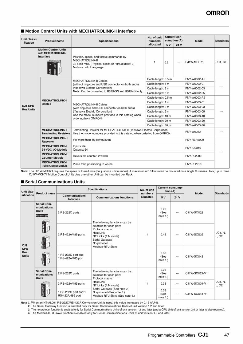
Programmable Controllers CJ1 47
■ Motion Control Units with MECHATROLINK-II interface
Note: The CJ1W-MCH71 requires the space of three Units (but just one unit number). A maximum of 10 Units can be mounted on a single CJ-series Rack, up to threeCJ1W-MCH71 Motion Control Units plus one other Unit can be mounted per Rack.
■ Serial Communications Units
Note 1. When an NT-AL001 RS-232C/RS-422A Conversion Unit is used, this value increases by 0.15 A/Unit. 2. The Serial Gateway function is enabled only for Serial Communications Units of unit version 1.2 and later.3. The no-protocol function is enabled only for Serial Communications Units of unit version 1.2 and later (and a CPU Unit of unit version 3.0 or later is also required).4. The Modbus-RTU Slave function is enabled only for Serial Communications Units of unit version 1.3 and later.
Unit classi-fication
Product name SpecificationsNo. of unit numbers allocated
Current con-sumption (A) Model Standards5 V 24 V
CJ1 CPU Bus Units
Motion Control Units with MECHATROLINK-II interface Position, speed, and torque commands by
MECHATROLINK-II32 axes max. (Physical axes: 30, Virtual axes: 2) Motion control language
1 0.6 --- CJ1W-MCH71 UC1, CE
MECHATROLINK-II Cables
MECHATROLINK-II Cables(without ring core and USB connector on both ends)(Yaskawa Electric Corporation)Note: Can be connected to R88D-GN and R88D-KN only.
Cable length: 0.5 m FNY-W6002-A5
---Cable length: 1 m FNY-W6002-01
Cable length: 3 m FNY-W6002-03
Cable length: 5 m FNY-W6002-05
MECHATROLINK-II Cables(with ring core and USB connector on both ends)(Yaskawa Electric Corporation)Use the model numbers provided in this catalog when ordering from OMRON.
Cable length: 0.5 m FNY-W6003-A5
---
Cable length: 1 m FNY-W6003-01
Cable length: 3 m FNY-W6003-03
Cable length: 5 m FNY-W6003-05
Cable length: 10 m FNY-W6003-10
Cable length: 20 m FNY-W6003-20
Cable length: 30 m FNY-W6003-30
MECHATROLINK-II Terminating Resistors
Terminating Resistor for MECHATROLINK-II (Yaskawa Electric Corporation)Use the model numbers provided in this catalog when ordering from OMRON.
FNY-W6022 ---
MECHATROLINK- II Repeater
For more than 15 slaves/30 m FNY-REP2000
---
MECHATROLINK-II 24-VDC I/O Module
Inputs: 64Outputs: 64
FNY-IO2310
MECHATROLINK-II Counter Module
Reversible counter, 2 words FNY-PL2900
MECHATROLINK-II Pulse Output Module
Pulse train positioning, 2 words FNY-PL2910
Unit clas-sification
Product nameSpecifications No. of unit
numbers allocated
Current consump-tion (A)
Model StandardsCommunications
InterfaceCommunications functions 5 V 24 V
CJ1 CPU Bus Units
Serial Com-munications Units 2 RS-232C ports
The following functions can be selected for each port:Protocol macroHost LinkNT Links (1:N mode)Serial GatewayNo-protocol Modbus-RTU Slave
1
0.29 (See
note 1.)--- CJ1W-SCU22
UC1, N, L, CE
2 RS-422A/485 ports 0.46 --- CJ1W-SCU32
1 RS-232C port and 1 RS-422A/485 port
0.38 (See
note 1.)--- CJ1W-SCU42
Serial Com-munications Units
2 RS-232C portsThe following functions can be selected for each port:Protocol macroHost LinkNT Links (1:N mode)Serial Gateway (See note 2.)No-protocol (See note 3.)Modbus-RTU Slave (See note 4.)
1
0.28 (See
note 1.)--- CJ1W-SCU21-V1
UC1, N, L, CE
2 RS-422A/485 ports 0.38 --- CJ1W-SCU31-V1
1 RS-232C port and 1 RS-422A/485 port
0.38 (See
note 1.)--- CJ1W-SCU41-V1
High-speed type

48 Programmable Controllers CJ1
� EtherNet/IP Unit
� Ethernet Unit
Note: Up to three Ethernet Units can be connected to a CJ1M-CPU1@-ETN CPU Unit.
� Industrial Switching Hubs
� Controller Link Units� Controller Link Units
Note: Use the following special cable for shielded, twisted-pair cable.• ESVC0.5 × 2C-13262 (Bando Electric Wire: Japanese Company)• ESNC0.5 × 2C-99-087B (Nihon Electric Wire & Cable Corporation: Japanese Company)• ESPC 1P × 0.5 mm2 (Nagaoka Electric Wire Co., Ltd.: Japanese Company)• Li2Y-FCY2 × 0.56qmm (Kromberg & Schubert, Komtec Department: German Company)• 1 × 2 × AWG-20PE+Tr.CUSN+PVC (Draka Cables Industrial: Spanish Company)• #9207 (Belden: US Company)
Unit clas-sification
Product name
Specifications
No. of unit numbers allocated
Current con-sumption (A)
Model StandardsCommunica-tions cable
Communications functions
Max.Units mountable
per CPU Unit
5 V 24 V
CJ1 CPU Bus Unit
EtherNet/IP Unit STP (shielded
twisted-pair) cable of category 5, 5e, or higher.
Tag data linkmessage service
8 1 0.41 --- CJ1W-EIP21UC1, N, L, CE
Unit clas-sification
Product name
Specifications
No. of unit numbers allocated
Current con-sumption (A)
Model StandardsCommunica-tions cable
Communications functions
Max.Units mountable
per CPU Unit
5 V 24 V
CJ1 CPU Bus Unit
Ethernet Unit
100Base-TX
FINS communications service (TCP/IP, UDP/IP), FTP server functions, socket services, mail transmission service, mail reception (remote command receive), automatic adjustment of PLC’s built-in clock, server/host name specifications
4(See note.)
1 0.37 --- CJ1W-ETN21UC1, N, L, CE
Product name Appearance
Specifications
AccessoriesCurrent
consumption (A)
Model StandardsFunctions
No. of ports
Failure detection
Industrial Switching Hubs
Quality of Service (QoS):EtherNet/IP control data priority
Failure detection:Broadcast storm and LSI error detection
10/100BASE-TX, Auto-Negotiation
3 No• Power supply
connector
0.08 W4S1-03BUC, CE
5 No 0.12 W4S1-05B
5 Yes
• Power supply connector
• Connector for informing error
0.12 W4S1-05C CE
Unit clas-sification
Product name
SpecificationsNo. of unit numbers allocated
Current consumption (A)
Model StandardsCommunications
cableCommunica-
tions typeDuplex support
Max. Units mountable per
CPU Unit5 V 24 V
CJ1 CPU Bus Unit
Controller Link Unit
Wired shielded twisted-pair cable (See note.)
Data links and message service
No 8 1 0.35 --- CJ1W-CLK23 UC1, N, L, CE

Programmable Controllers CJ1 49
● Controller Link Support Boards
Note: The CD-ROM contains the following software.• Controller Link (PCI) Driver• FinsGateway Version 2003 (PCI-CLK Edition)• FinsGateway Version 3 (PCI-CLK Edition)• Setup Diagnostic Utility• C Library
● Repeater Units
Note 1. Using Repeater Units enables T-branches and long-distance wiring for Wired Controller Link networks. 62-node configurations, and converting part of the net-work to optical cable.
2. When using wire-to-optical (H-PCF) cable, use a H-PCF cable (for both Controller Link and SYSMAC LINK) or a H-PCF optical fiber cable with connector.3. When using wire-to-optical (GI) cable, use a GI optical cable (for Controller Link).
● Relay Terminal Block
Note: Controller Link Units can be replaced without stopping the communications of the entire network if a Relay Terminal Block is installed in advance on the Unit ina Wired Controller Link network. Relay Blocks cannot be used on Controller Link Support Boards.
● H-PCF Cables and Optical Connectors
Unit classification
Specification
Accessories Model StandardsCommunications cable
Communications type
Controller Link Support Board for PCI Bus Wired shielded
twisted-pair cableData link and message service
• CD-ROM × 1 (See note.)• INSTALLATION GUIDE (W467) × 1• Communications connector × 1
3G8F7-CLK23-E CE
Unit classification Specifications Model Standards
Controller Link Repeater Unit
Wire-to-wire Model CS1W-RPT01
UC1, CEWire-to-Optical (H-PCF) Model (See note 2.) CS1W-RPT02
Wire-to-Optical (GI) Model (See note 3.) CS1W-RPT03
Unit classification Specifications Model Standards
Relay Terminal Block for Wired Controller Link Unit
Use for Wired Controller Link Units (set of 5). CJ1W-TB101 ---
Name Application/construction Specifications Model Standards
Optical Fiber Cables
ControllerLink, SYSMACLINK, SYSBUS
(1) Optical fiber single-core cord(2) Tension member (plastic-
sheathed wire)(3) Filler (plastic)(4) Filler surrounding signal wires
(plastic, yarn, or fiber)(5) Holding tape (plastic)(6) Heat-resistant PV sheath
Two-core optical cable with tension member
Black 10 m S3200-HCCB101
---
Black 50 m S3200-HCCB501
Black 100 m S3200-HCCB102
Black 500 m S3200-HCCB502
Black 1,000 m S3200-HCCB103
Orange 10 m S3200-HCCO101
Orange 50 m S3200-HCCO501
Orange 100m S3200-HCCO102
Orange 500 m S3200-HCCO502
Orange 1,000 m S3200-HCCO103
Optical Connec-tors (Crimp-cut)
CS1W-RPT02
Half lock S3200-COCF2571
Full lock S3200-COCF2071
CS1W-RPT01PWRT/R1T/R2
SL1
TER SW
TER SW
ON
SL2
DC24VINPUT
1 BAUD2 RATE
SW1
(1)(2)
(4)(3)
(5)(6)

50 Programmable Controllers CJ1
● H-PCF Optical Fiber Cables with Connectors (Black Composite Cables with Two-Optical Lines and Two Power Supply Lines)
• Cable LengthThe following cable lengths are available: 2 m, 5 m, 15 m, 20 m.
For lengths of 21 m or more, contact your OMRON sales repre-
sentative.
• Model Numbers
• Optical Connector Assembly Tool
Note: There is a risk of quality problems when using cables assembled by typ-ical users, so we recommend purchasing cables with preattached con-nectors or having a qualified technician assemble the cables.Optical connectors for H-PCF Optical Cables with Connectors are adhe-sive polished.
● GI Optical CablesA qualified technician must select, assemble, and install GI
Optical Fiber Cable, so always let an optical cable specialist
handle the GI cable.
Usable Optical Cables and Optical Connectors
• Optical fiber types: Graded, indexed, multi-mode, all quartz
glass, fiber (GI-type AGF cable)
• Optical fiber construction (core diameter/clad diameter):
62.5/125 μm or 50/125 μm
• Optical fiber optical characteristics of optical fiber: Refer to the
tables.
• Optical connector: ST connector (IEC-874-10)
• 50/125 μm AGF Cable
Lf is fiber length in km, Ta is ambient temperature, and λ: is the peak wave-length of the test light source.
• 62.5/125 μm AGF Cable
Lf is fiber length in km, Ta is ambient temperature, and λ is the peak wavelength of the test light source.
Application Appearance ModelStan-dards
Controller Link, SYSMAC Link
S3200-CN@@@-20-20
---S3200-CN@@@-20-25
S3200-CN@@@-25-25
Product Name
Applicable Unit Model ManufacturerStan-dards
Optical Fiber Assem-bly Tool (See note.)
This tool is used on site for mounting crimp-cut connectors and hard plastic-clad silica opti-cal fiber for optical transmission systems of C-series SYSBUS, SYSMAC LINK, and Controller Link.
CAK-0057
Sumitomo Electric Industries, Ltd.
---
@@@201
501
102
152
202
Length2 m
5 m
10 m
15 m
20 m
20
25
Number Connector appearance
Full lock
Half lock
Lengths of 2 m, 5 m, 10 m, 15 m, and 20 m
Example: S3200-CN@@@@@@-20-25(1) (2) (3)
Length of 21 m or more
Example: S3200-CN-20-20(1) (3) Specify the
cable length in meters.
(2)Cable Length
Cable length
(1)H-PCF optical fiber cable
(1) Connectors at Both Ends
Item Minimum Standard Maximum Remarks
Numerical Aperture (N.A)
--- 0.21 --- ---
Transmis-sion loss (dB)
--- ---
3.0 Lf0.5 km ≤ Lf
λ = 0.8 μmTa = 25°C
3.0 Lf + 0.2
0.2 km ≤ Lf ≤ 0.5 km
3.0 Lf + 0.4
Lf ≤ 0.2 km
Connec-tion loss (dB)
--- --- 1.0λ = 0.8 μm, one location
Transmis-sion band-width (MHz-km)
500 --- --- λ = 0.85μm (LD)
Item Minimum Standard Maximum Remarks
Numerical Aperture (N.A)
--- 0.28 --- ---
Transmis-sion loss (dB)
--- ---
3.5 Lf0.5 km ≤
Lf
λ = 0.8 μmTa = 25°C
3.5 Lf + 0.2
0.2 km ≤ Lf ≤ 0.5
km
3.5 Lf + 0.4
Lf ≤ 0.2 km
Connec-tion loss (dB)
--- --- 1.0λ = 0.8 μm, one location
Transmis-sion band-width (MHz-km)
200 --- --- λ = 0.85 μm (LD)

Programmable Controllers CJ1 51
■ FL-net Unit
■ DeviceNet Unit
■ CompoNet Master Unit
■ CompoBus/S Master Unit
Unit classifi-cation
Product name
SpecificationsNo. of unit numbers allocated
Current con-sumption (A)
Model StandardsCommunica-
tions interfaceCommunications
functions
Max. Units mountable
per CPU Units5 V 24 V
CJ1 CPU Bus Units
FL-net Unit
100Base-TX
With FL-net Ver. 2.0 specifications (OPCN-2)Data links and message service
4 1 0.37 --- CJ1W-FLN22 UC1, CE
Unit classifi-cation
Product name Specifications Communications typeNo. of unit numbers allocated
Current con-sumption (A) Model Standards
5 V 24 V
CJ1 CPU Bus Units
DeviceNet Unit
Functions as master and/or slave; allows control of 32,000 points max. per master.
• Remote I/O communications master (fixed or user-set allocations)
• Remote I/O communications slave (fixed or user-set allocations)
• Message communications
1 0.29 --- CJ1W-DRM21UC1, N, L, CE
Unit classifi-cation
Product name
Specifications No. of unit numbers allocated
Current con-sumption (A)
Model StandardsCommunications
functionsNo. of I/O points per Master Unit 5 V 24 V
CJ1 Special I/O Units
CompoNet Master Unit • Remote I/O
communications• Message
communications
Word Slaves: 2,048 max. (1.024 inputs and 1,024 outputs)Bit Slaves: 512 max. (256 inputs and 256 outputs)
1, 2, 4, or 8 0.4 ---CJ1W-CRM21
U, U1, N, L, CE,
Unit classifi-cation
Product name
SpecificationsNo. of unit numbers allocated
Current con-sumption (A)
Model StandardsCommunications
functionsNo. of I/O points
Max. Units mountable per
CPU Unit5 V 24 V
CJ1 Special I/O Units
CompoBus/S Master Unit
Remote I/O communications
256 max.(128 inputs and 128 outputs)
401 or 2
(variable) 0.15 --- CJ1W-SRM21UC1, N, L, CE, 128 max.
(64 inputs and 64 outputs)

52 Programmable Controllers CJ1
■ ID Sensor Units
Note: To use a V680-H01 Antenna, refer to the V680 Series RFID System Catalog (Cat. No. Q151).
■SPU Unit (High-speed Data Storage Unit)
Note: SPU-Console versions lower than version 2.0 cannot connect to SPU Units with unit versions of 2.0 or later.
Unit clas-sification
Product name
SpecificationsNo. of unit numbers allocated
Current consumption (A)
Model Standards
Connected ID SystemsNo. of con-nected R/W
heads
External power supply
5 V 24 V
CJ1 CPU Bus Units
ID Sensor Units
V680 Series RFID System
1
Not required.
1 0.260.13 (See note.)
CJ1W-V680C11
UC, CE
2 2 0.32 0.26 CJ1W-V680C12
V600 Series RFID System
1
Not required.
1 0.26 0.12 CJ1W-V600C11
UC, CE
2 2 0.32 0.24 CJ1W-V600C12
Unit classification
Product nameSpecifications No. of unit
numbers allocated
Current consumption
(A) Model Standards
PC Card slot Ethernet (LAN) port 5 V 24 V
CJ1 CPU Bus Units
SPU Unit (High-speed Data Storage Unit)
CF Card Type I/II × 1 slotUse an OMRON HMC-EF@@@ Memory Card.
1 port (10/100Base-TX) 1 0.56 --- CJ1W-SPU01-V2 UC1, CE
SPU-Console (See note.)
Functions: Unit settings, sampling settings, etc., for High-speed Data Collection Units (required for making settings for this Unit)
OS: Windows XP, Vista, 7 or 8WS02-SPTC1-V2
---
SPU Unit Data Man-agement Middleware
Function: Data files collected by SPU Data Management Middleware are automatically acquired at the personal computer, and can be registered in a database.
OS: Windows XP, Vista, 7 or 8
1 license WS02-EDMC1-V2
5 licenses WS02-EDMC1-V2L05
Memory Cards
Flash memory, 128 MB Note:Memory Card is required for data collection.
HMC-EF183
Flash memory, 256 MB HMC-EF283
Flash memory, 512 MB HMC-EF583

Terms and Conditions AgreementRead and understand this catalog.
Please read and understand this catalog before purchasing the products. Please consult your OMRON representative if you have any questions or comments.
Warranties.(a) Exclusive Warranty. Omron’s exclusive warranty is that the Products will be free from defects in materials and workmanship
for a period of twelve months from the date of sale by Omron (or such other period expressed in writing by Omron). Omron disclaims all other warranties, express or implied.
(b) Limitations. OMRON MAKES NO WARRANTY OR REPRESENTATION, EXPRESS OR IMPLIED, ABOUT NON-INFRINGEMENT, MERCHANTABILITY OR FITNESS FOR A PARTICULAR PURPOSE OF THE PRODUCTS. BUYER ACKNOWLEDGES THAT IT ALONE HAS DETERMINED THAT THE PRODUCTS WILL SUITABLY MEET THE REQUIREMENTS OF THEIR INTENDED USE.
Omron further disclaims all warranties and responsibility of any type for claims or expenses based on infringement by the Products or otherwise of any intellectual property right. (c) Buyer Remedy. Omron’s sole obligation hereunder shall be, at Omron’s election, to (i) replace (in the form originally shipped with Buyer responsible for labor charges for removal or replacement thereof) the non-complying Product, (ii) repair the non-complying Product, or (iii) repay or credit Buyer an amount equal to the purchase price of the non-complying Product; provided that in no event shall Omron be responsible for warranty, repair, indemnity or any other claims or expenses regarding the Products unless Omron’s analysis confirms that the Products were properly handled, stored, installed and maintained and not subject to contamination, abuse, misuse or inappropriate modification. Return of any Products by Buyer must be approved in writing by Omron before shipment. Omron Companies shall not be liable for the suitability or unsuitability or the results from the use of Products in combination with any electrical or electronic components, circuits, system assemblies or any other materials or substances or environments. Any advice, recommendations or information given orally or in writing, are not to be construed as an amendment or addition to the above warranty.
See http://www.omron.com/global/ or contact your Omron representative for published information.
Limitation on Liability; Etc.OMRON COMPANIES SHALL NOT BE LIABLE FOR SPECIAL, INDIRECT, INCIDENTAL, OR CONSEQUENTIAL DAMAGES, LOSS OF PROFITS OR PRODUCTION OR COMMERCIAL LOSS IN ANY WAY CONNECTED WITH THE PRODUCTS, WHETHER SUCH CLAIM IS BASED IN CONTRACT, WARRANTY, NEGLIGENCE OR STRICT LIABILITY.
Further, in no event shall liability of Omron Companies exceed the individual price of the Product on which liability is asserted.
Suitability of Use.Omron Companies shall not be responsible for conformity with any standards, codes or regulations which apply to the combination of the Product in the Buyer’s application or use of the Product. At Buyer’s request, Omron will provide applicable third party certification documents identifying ratings and limitations of use which apply to the Product. This information by itself is not sufficient for a complete determination of the suitability of the Product in combination with the end product, machine, system, or other application or use. Buyer shall be solely responsible for determining appropriateness of the particular Product with respect to Buyer’s application, product or system. Buyer shall take application responsibility in all cases.
NEVER USE THE PRODUCT FOR AN APPLICATION INVOLVING SERIOUS RISK TO LIFE OR PROPERTY OR IN LARGE QUANTITIES WITHOUT ENSURING THAT THE SYSTEM AS A WHOLE HAS BEEN DESIGNED TO ADDRESS THE RISKS, AND THAT THE OMRON PRODUCT(S) IS PROPERLY RATED AND INSTALLED FOR THE INTENDED USE WITHIN THE OVERALL EQUIPMENT OR SYSTEM.
Programmable Products.Omron Companies shall not be responsible for the user’s programming of a programmable Product, or any consequence thereof.
Performance Data.Data presented in Omron Company websites, catalogs and other materials is provided as a guide for the user in determining suitability and does not constitute a warranty. It may represent the result of Omron’s test conditions, and the user must correlate it to actual application requirements. Actual performance is subject to the Omron’s Warranty and Limitations of Liability.
Change in Specifications.Product specifications and accessories may be changed at any time based on improvements and other reasons. It is our practice to change part numbers when published ratings or features are changed, or when significant construction changes are made. However, some specifications of the Product may be changed without any notice. When in doubt, special part numbers may be assigned to fix or establish key specifications for your application. Please consult with your Omron’s representative at any time to confirm actual specifications of purchased Product.
Errors and Omissions.Information presented by Omron Companies has been checked and is believed to be accurate; however, no responsibility is assumed for clerical, typographical or proofreading errors or omissions.

Authorized Distributor:
In the interest of product improvement, specifications are subject to change without notice.
Cat. No. P052-E1-12 Printed in Japan
0412 (0901)
© OMRON Corporation 2001-2012 All Rights Reserved.
OMRON Corporation Industrial Automation Company
OMRON ELECTRONICS LLCOne Commerce Drive Schaumburg,IL 60173-5302 U.S.A.Tel: (1) 847-843-7900/Fax: (1) 847-843-7787
Regional HeadquartersOMRON EUROPE B.V.Wegalaan 67-69-2132 JD HoofddorpThe NetherlandsTel: (31)2356-81-300/Fax: (31)2356-81-388
Contact: www.ia.omron.comTokyo, JAPAN
OMRON ASIA PACIFIC PTE. LTD.No. 438A Alexandra Road # 05-05/08 (Lobby 2), Alexandra Technopark, Singapore 119967Tel: (65) 6835-3011/Fax: (65) 6835-2711
OMRON (CHINA) CO., LTD.Room 2211, Bank of China Tower, 200 Yin Cheng Zhong Road, PuDong New Area, Shanghai, 200120, China CSM_7_1_0314Tel: (86) 21-5037-2222/Fax: (86) 21-5037-2200