
Program Information Mobile Hydraulics, Mobile Electronics ... · Gears BODAS Mobile Electronics...
108
Linear Motion and Assembly Technologies Service Pneumatics Hydraulics Electric Drives and Controls Program Information Mobile Hydraulics, Mobile Electronics, Gears The Drive & Control Company
Transcript of Program Information Mobile Hydraulics, Mobile Electronics ... · Gears BODAS Mobile Electronics...
Linear Motion andAssembly Technologies ServicePneumaticsHydraulics
Electric Drives and Controls
Program Information Mobile Hydraulics,Mobile Electronics, Gears
The Drive & Control Company

3
Welcome to the World of Mobile Hydraulics
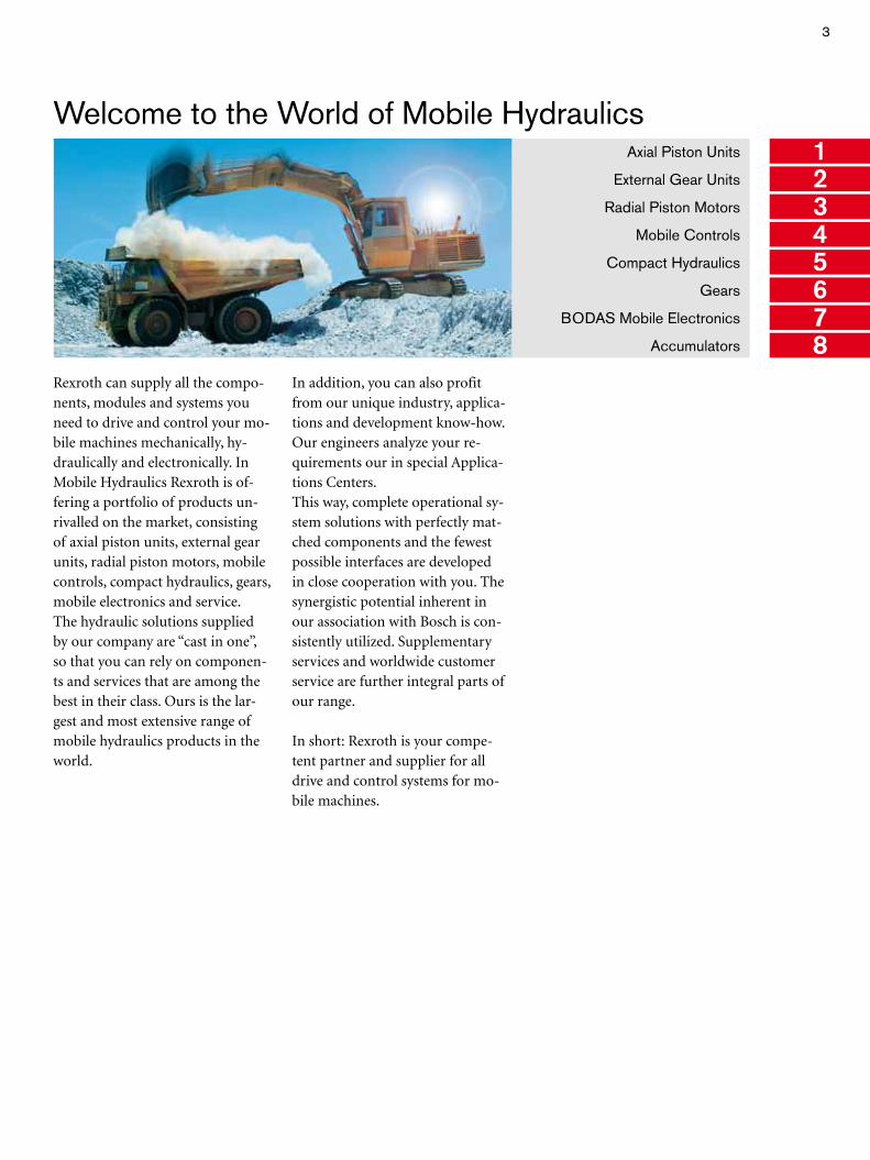
In addition, you can also profit from our unique industry, applica-tions and development know-how. Our engineers analyze your re-quirements our in special Applica-tions Centers.This way, complete operational sy-stem solutions with perfectly mat-ched components and the fewest possible interfaces are developed in close cooperation with you. The synergistic potential inherent in our association with Bosch is con-sistently utilized. Supplementary services and worldwide customer service are further integral parts of our range.
In short: Rexroth is your compe-tent partner and supplier for all drive and control systems for mo-bile machines.
Axial Piston Units
External Gear Units
Radial Piston Motors
Mobile Controls
Compact Hydraulics
Gears
BODAS Mobile Electronics
Accumulators
Rexroth can supply all the compo-nents, modules and systems you need to drive and control your mo-bile machines mechanically, hy-draulically and electronically. In Mobile Hydraulics Rexroth is of-fering a portfolio of products un-rivalled on the market, consisting of axial piston units, external gear units, radial piston motors, mobile controls, compact hydraulics, gears, mobile electronics and service. The hydraulic solutions supplied by our company are “cast in one”, so that you can rely on componen-ts and services that are among the best in their class. Ours is the lar-gest and most extensive range of mobile hydraulics products in the world.
1
8
34567
2
4
1Contents
Axial Piston Units 9
Fixed pumps A2FO 10 A4FO 11 KFA 12Variable pumps KVA 13 A10VO/5 14 A10VNO 15 A10VO/3 16 A11VO 17 A4VSO 18 A7VO 19 A20VO 20 A8VO 21 A4VG 22 A10VG 23 A4VTG 24 A4CSG 25Fixed motors A2FM 26 A4FM 27 A10FM 28Variable motors A6VM 29 A10VM 30
External Gear Units 31
External gear pumps Standard version 32 SILENCE version 34External gear motors 35Hydrostatic fan drive 36
Radial Piston Motors 37
Radial piston motors MCR 38
Mobile Controls 41
Control blocks Open Center control block SM 42 Open Center control block MO 43 Open Center control block M8 44 LUDV control block SX 45 LUDV control block M6 46 LUDV control block M7 47 Load sensing control block SP-08 48 Load sensing control block M4 49 Load sensing control block SB12-LS 50 Load sensing control block SB23-LS 51Valve modules Control valves EHR 52 Central hydraulics for tractors CHP 53 Flow divider MH2FA/RTM 54 Pipe burst safety valves MHRB 55 Check-Q-meter FD 55 Stabilizing module RSM2 56 Pilot oil supply systems MHSTE 56 Pressure, flow, check valves 57
2
3
4
5
5
Brakes Hydraulic remotely powered brakes LT 58 Trailer brake valves BV1 59Steering units Hydrostatic steering units LAG 60 Priority valves LPS 61 Steering columns LAB and sensors 61Pilot control devices Hydraulic and electronic pilot control devices TH 62
Compact Hydraulics 63
Cartridge valves: Counterbalance valves 64 Mechanical valves 65 Solenoid operated directional valves, poppet type 66 Solenoid operated direct. poppet valves KSDE and directional spool valves KKDE 67 Prop. pressure relief valves KB.S and pressure reducing valves FTDRE / MHDRE 68 Insert type valves 69Standard manifolds 70Customized integrated circuits 71Pressure, flow, pilot operated check valves 72Motion control valves 73Cylinder safety lock valve – A-VBC 74Heavy duty priority flow control 75Compact power module Series KE 76 Series K 77 Series ME 78Inline valves 79Flow diverters 80Modular directional valves 81CETOP 2 (NG4) 82Special directional valves 83
Gears 85
Travel drives HYDROTRAC GFT 86 HYDROTRAC GFT-A10VT 87Swing drives MOBILEX GFB 88 MOBILEX GFB-A10FD 89Winch drives MOBILEX GFT-W 90Planetary gearboxes REDULUS GMH/GME 91Generator gear units REDULUS GPV for wind turbines from 300 to 5,000 kW 92Pitch and yaw drives MOBILEX GFB 93
BODAS Mobile Electronics 95
BODAS controller RC 96BODAS application software 97BODAS tools 98BODAS sensors 99BODAS joysticks and display 100Analog amplifier RA 101Electrohydraulic hitch control for tractors EHR 102Electrohydraulic header height control EMR 103Automatic fan control AFC 104
Accumulators 105
Hydropneumatic accumulators and accessories for accumulators 106
6
7
8
6
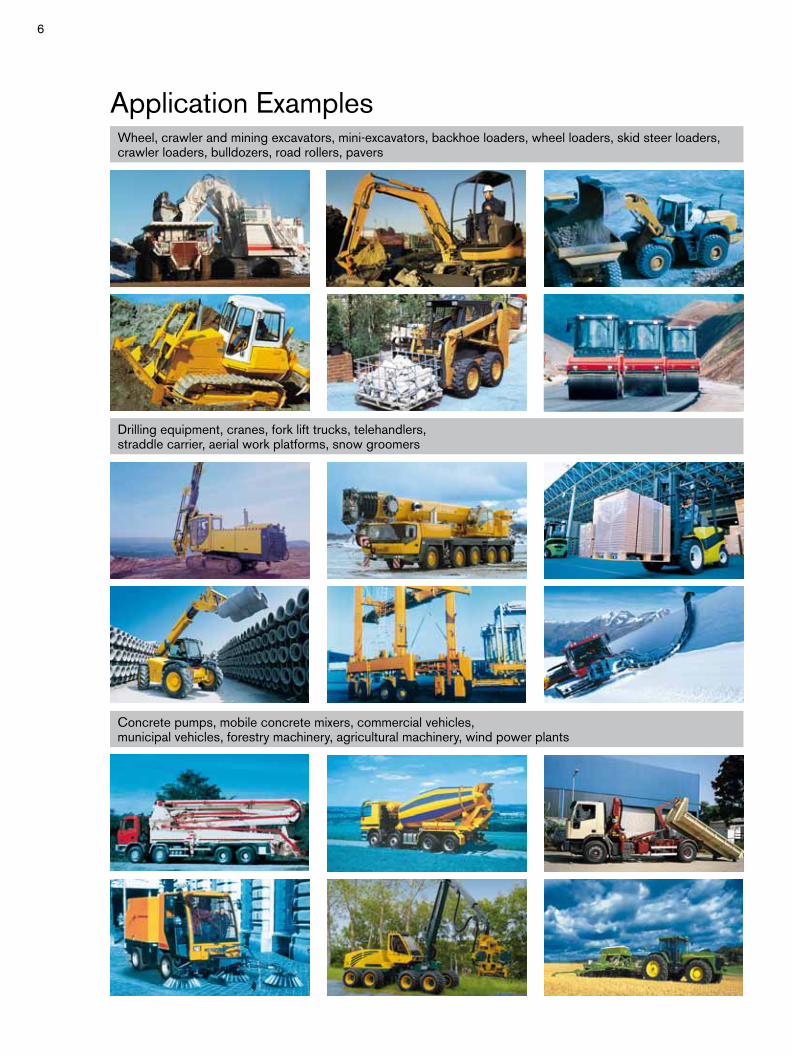
Application ExamplesWheel, crawler and mining excavators, mini-excavators, backhoe loaders, wheel loaders, skid steer loaders, crawler loaders, bulldozers, road rollers, pavers
Concrete pumps, mobile concrete mixers, commercial vehicles,municipal vehicles, forestry machinery, agricultural machinery, wind power plants
Drilling equipment, cranes, fork lift trucks, telehandlers,straddle carrier, aerial work platforms, snow groomers
7
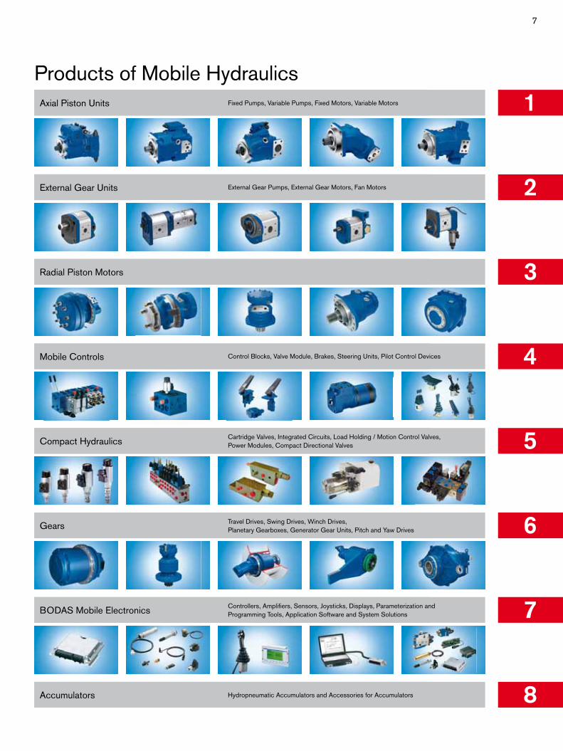
Products of Mobile Hydraulics1Axial Piston Units Fixed Pumps, Variable Pumps, Fixed Motors, Variable Motors
External Gear Units External Gear Pumps, External Gear Motors, Fan Motors
Radial Piston Motors
Mobile Controls
Compact Hydraulics Cartridge Valves, Integrated Circuits, Load Holding / Motion Control Valves, Power Modules, Compact Directional Valves
Gears Travel Drives, Swing Drives, Winch Drives,Planetary Gearboxes, Generator Gear Units, Pitch and Yaw Drives
BODAS Mobile Electronics Controllers, Amplifiers, Sensors, Joysticks, Displays, Parameterization and Programming Tools, Application Software and System Solutions
2
3
4
5
6
7
8Accumulators
Control Blocks, Valve Module, Brakes, Steering Units, Pilot Control Devices
Hydropneumatic Accumulators and Accessories for Accumulators

8
9
Axial Piston Units
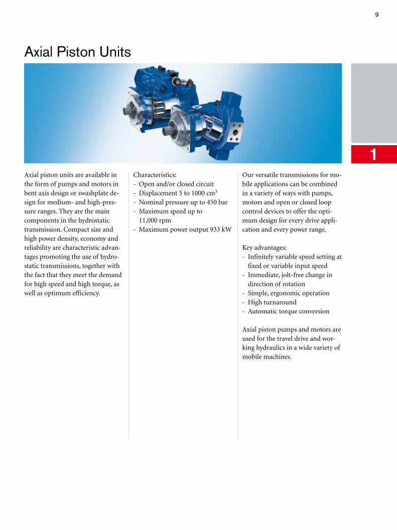
1Axial piston units are available in the form of pumps and motors in bent axis design or swashplate de-sign for medium- and high-pres-sure ranges. They are the main components in the hydrostatic transmission. Compact size and high power density, economy and reliability are characteristic advan-tages promoting the use of hydro-static transmissions, together with the fact that they meet the demand for high speed and high torque, as well as optimum efficiency.
Characteristics: - Open and/or closed circuit - Displacement 5 to 1000 cm3
- Nominal pressure up to 450 bar - Maximum speed up to
11,000 rpm - Maximum power output 933 kW
Our versatile transmissions for mo-bile applications can be combined in a variety of ways with pumps, motors and open or closed loop control devices to offer the opti-mum design for every drive appli-cation and every power range.
Key advantages: - Infinitely variable speed setting at
fixed or variable input speed - Immediate, jolt-free change in
direction of rotation- Simple, ergonomic operation- High turnaround - Automatic torque conversion
Axial piston pumps and motors are used for the travel drive and wor-king hydraulics in a wide variety of mobile machines.
10 Axial Piston Units
Fixed Pump A2FO
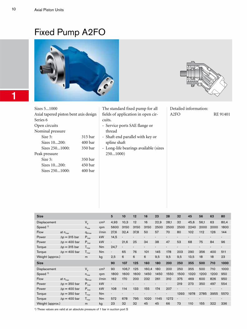
1Sizes 5...1000Axial tapered piston bent axis designSeries 6Open circuitsNominal pressure Size 5: 315 bar Sizes 10...200: 400 bar Sizes 250...1000: 350 barPeak pressure Size 5: 350 bar Sizes 10...200: 450 bar Sizes 250...1000: 400 bar
The standard fixed pump for all fields of application in open cir-cuits.- Service ports SAE flange or
thread- Shaft end parallel with key or
spline shaft- Long-life bearings available (sizes
250...1000)
Detailed information:A2FO RE 91401
Size 5 10 12 16 23 28 32 45 56 63 80
Displacement Vg cm³ 4,93 10,3 12 16 22,9 28,1 32 45,6 56,1 63 80,4Speed 1) nmax rpm 5600 3150 3150 3150 2500 2500 2500 2240 2000 2000 1800Flow at nmax qVmax l/min 27,6 32,4 37,8 50 57 70 80 102 112 126 144Power Δp = 315 bar Pmax kW 14,5 - - - - - - - - - -Power Δp = 400 bar Pmax kW - 21,6 25 34 38 47 53 68 75 84 96Torque Δp = 315 bar Tmax Nm 24,7 - - - - - - - - - -Torque Δp = 400 bar Tmax Nm - 65 76 101 145 178 203 290 356 400 511Weight (approx.) m kg 2,5 6 6 6 9,5 9,5 9,5 13,5 18 18 23
Size 90 107 125 160 180 200 250 355 500 710 1000
Displacement Vg cm³ 90 106,7 125 160,4 180 200 250 355 500 710 1000Speed 1) nmax rpm 1800 1600 1600 1450 1450 1550 1500 1320 1200 1200 950Flow at nmax qVmax l/min 162 170 200 232 261 310 375 469 600 826 950Power Δp = 350 bar Pmax kW - - - - - - 219 273 350 497 554Power Δp = 400 bar Pmax kW 108 114 133 155 174 207 - - - - -Torque Δp = 350 bar Tmax Nm - - - - - - 1393 1978 2785 3955 5570Torque Δp = 400 bar Tmax Nm 572 678 795 1020 1145 1272 - - - - -Weight (approx.) m kg 23 32 32 45 45 66 73 110 155 322 336
¹) These values are valid at an absolute pressure of 1 bar in suction port S
11
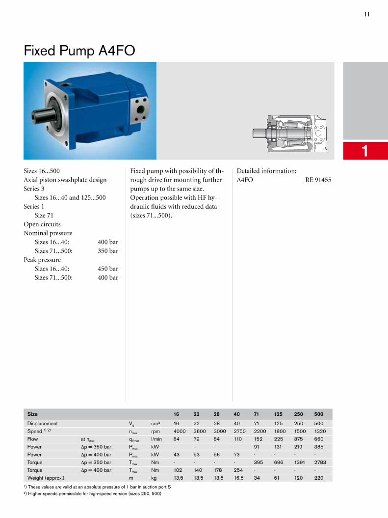
Fixed Pump A4FO
1Sizes 16...500Axial piston swashplate designSeries 3 Sizes 16...40 and 125...500Series 1 Size 71Open circuitsNominal pressure Sizes 16...40: 400 bar Sizes 71...500: 350 barPeak pressure Sizes 16...40: 450 bar Sizes 71...500: 400 bar
Fixed pump with possibility of th-rough drive for mounting further pumps up to the same size.Operation possible with HF hy-draulic fluids with reduced data (sizes 71...500).
Detailed information:A4FO RE 91455
Size 16 22 28 40 71 125 250 500
Displacement Vg cm³ 16 22 28 40 71 125 250 500Speed 1) 2) nmax rpm 4000 3600 3000 2750 2200 1800 1500 1320Flow at nmax qVmax l/min 64 79 84 110 152 225 375 660Power Δp = 350 bar Pmax kW - - - - 91 131 219 385Power Δp = 400 bar Pmax kW 43 53 56 73 - - - -Torque Δp = 350 bar Tmax Nm - - - - 395 696 1391 2783Torque Δp = 400 bar Tmax Nm 102 140 178 254 - - - -Weight (approx.) m kg 13,5 13,5 13,5 16,5 34 61 120 220
¹) These values are valid at an absolute pressure of 1 bar in suction port S²) Higher speeds permissible for high-speed version (sizes 250, 500)
12 Axial Piston Units
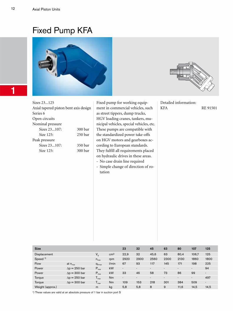
Fixed Pump KFA
1Sizes 23...125Axial tapered piston bent axis designSeries 6Open circuitsNominal pressure Sizes 23...107: 300 bar Size 125: 250 barPeak pressure Sizes 23...107: 350 bar Size 125: 300 bar
Fixed pump for working equip-ment in commercial vehicles, such as street tippers, dump trucks, HGV loading cranes, tankers, mu-nicipal vehicles, special vehicles, etc.These pumps are compatible with the standardized power take-offs on HGV motors and gearboxes ac-cording to European standards.They fulfill all requirements placed on hydraulic drives in these areas.- No case drain line required- Simple change of direction of ro-
tation
Detailed information:KFA RE 91501
Size 23 32 45 63 80 107 125
Displacement Vg cm³ 22,9 32 45,6 63 80,4 106,7 125Speed 1) nmax rpm 2920 2900 2560 2300 2130 1860 1800Flow at nmax qVmax l/min 67 93 117 145 171 198 225Power Δp = 250 bar Pmax kW - - - - - - 94Power Δp = 300 bar Pmax kW 33 46 58 73 86 99 -Torque Δp = 250 bar Tmax Nm - - - - - - 497Torque Δp = 300 bar Tmax Nm 109 153 218 301 384 509 -Weight (approx.) m kg 5,8 5,8 8 9 11,6 14,5 14,5
¹) These values are valid at an absolute pressure of 1 bar in suction port S
13
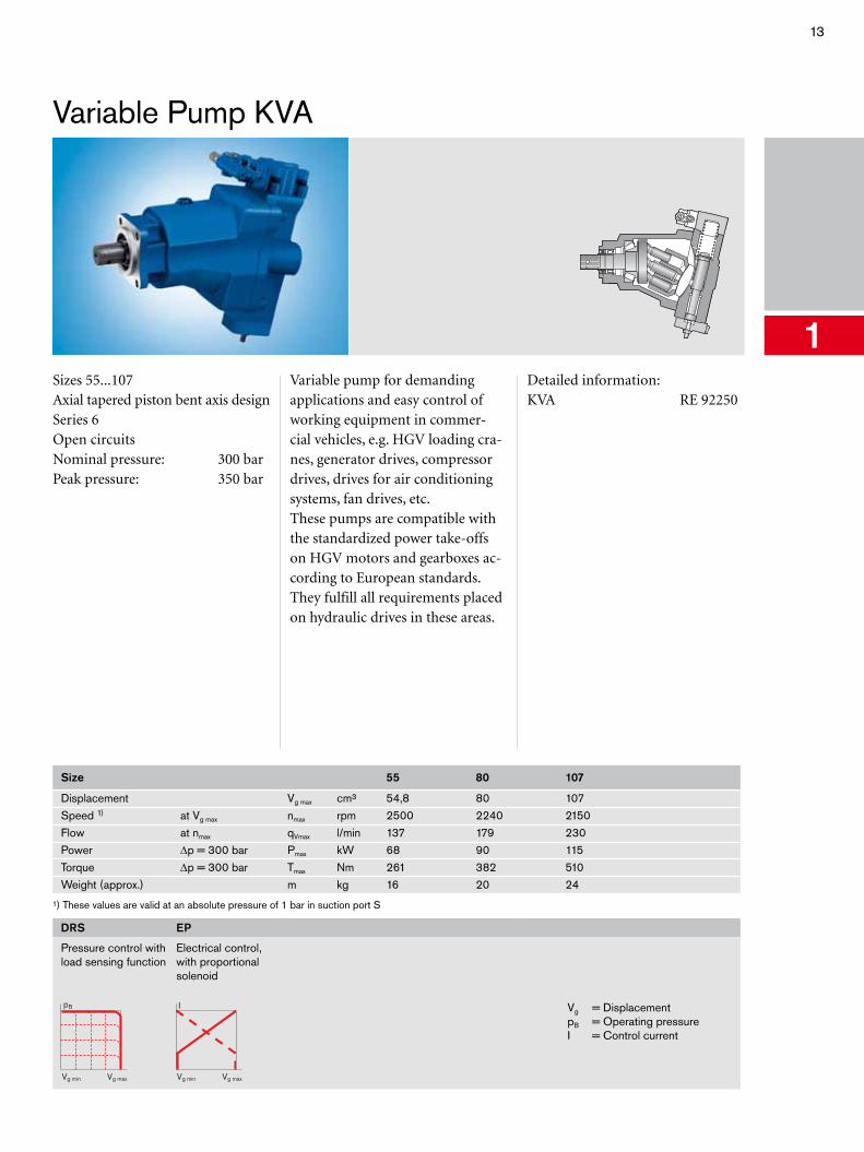
Variable Pump KVA
1Sizes 55...107Axial tapered piston bent axis designSeries 6Open circuitsNominal pressure: 300 barPeak pressure: 350 bar
Variable pump for demanding applications and easy control of working equipment in commer-cial vehicles, e.g. HGV loading cra-nes, generator drives, compressor drives, drives for air conditioning systems, fan drives, etc.These pumps are compatible with the standardized power take-offs on HGV motors and gearboxes ac-cording to European standards.They fulfill all requirements placed on hydraulic drives in these areas.
Detailed information:KVA RE 92250
Size 55 80 107
Displacement Vg max cm³ 54,8 80 107Speed 1) at Vg max nmax rpm 2500 2240 2150Flow at nmax qVmax l/min 137 179 230Power Δp = 300 bar Pmax kW 68 90 115Torque Δp = 300 bar Tmax Nm 261 382 510Weight (approx.) m kg 16 20 24
¹) These values are valid at an absolute pressure of 1 bar in suction port S
DRS
Pressure control with load sensing function
pB
Vg maxVg min
EP
Electrical control, with proportional solenoid
I
Vg maxVg min
Vg = DisplacementpB = Operating pressureI = Control current
14 Axial Piston Units
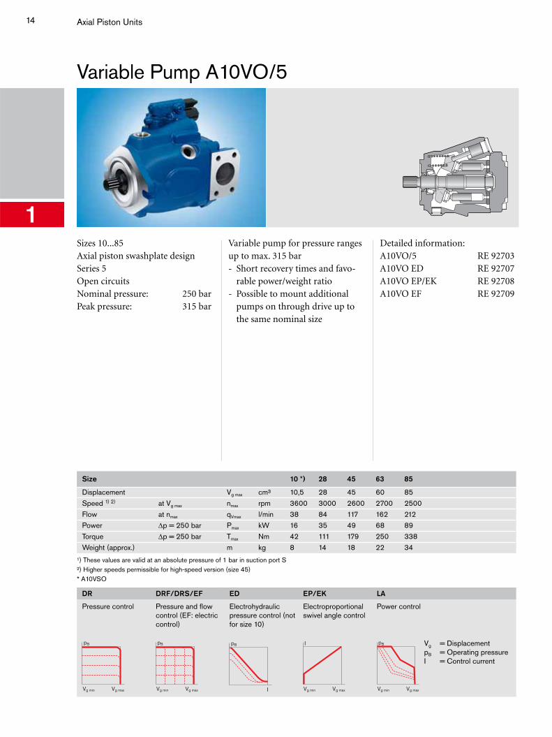
Variable Pump A10VO/5
1Sizes 10...85Axial piston swashplate designSeries 5Open circuitsNominal pressure: 250 barPeak pressure: 315 bar
Variable pump for pressure ranges up to max. 315 bar- Short recovery times and favo-
rable power/weight ratio- Possible to mount additional
pumps on through drive up to the same nominal size
Detailed information:A10VO/5 RE 92703A10VO ED RE 92707A10VO EP/EK RE 92708A10VO EF RE 92709
Size 10 *) 28 45 63 85
Displacement Vg max cm³ 10,5 28 45 60 85Speed 1) 2) at Vg max nmax rpm 3600 3000 2600 2700 2500Flow at nmax qVmax l/min 38 84 117 162 212Power Δp = 250 bar Pmax kW 16 35 49 68 89Torque Δp = 250 bar Tmax Nm 42 111 179 250 338Weight (approx.) m kg 8 14 18 22 34
¹) These values are valid at an absolute pressure of 1 bar in suction port S²) Higher speeds permissible for high-speed version (size 45)* A10VSO
DR
Pressure control
pB
Vg maxVg min
DRF/DRS/EF
Pressure and flow control (EF: electric control)
pB
Vg maxVg min
ED
Electrohydraulic pressure control (not for size 10)
pB
I
EP/EK
Electroproportional swivel angle control
I
Vg maxVg min
LA
Power control
pB
Vg maxVg min
Vg = DisplacementpB = Operating pressureI = Control current
15
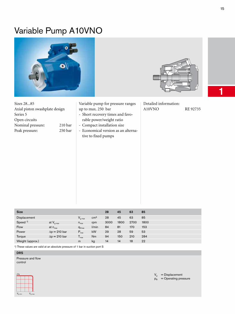
Variable Pump A10VNO
1Sizes 28...85Axial piston swashplate designSeries 5Open circuitsNominal pressure: 210 barPeak pressure: 250 bar
Variable pump for pressure ranges up to max. 250 bar- Short recovery times and favo-
rable power/weight ratio- Compact installation size- Economical version as an alterna-
tive to fixed pumps
Detailed information:A10VNO RE 92735
Size 28 45 63 85
Displacement Vg max cm³ 28 45 63 85Speed 1) at Vg max nmax rpm 3000 1800 2700 1800Flow at nmax qVmax l/min 84 81 170 153Power Δp = 210 bar Pmax kW 29 28 59 53Torque Δp = 210 bar Tmax Nm 94 150 210 284Weight (approx.) m kg 14 14 18 22
¹) These values are valid at an absolute pressure of 1 bar in suction port S
DRS
Pressure and flow control
pB
Vg maxVg min
Vg = DisplacementpB = Operating pressure
16 Axial Piston Units
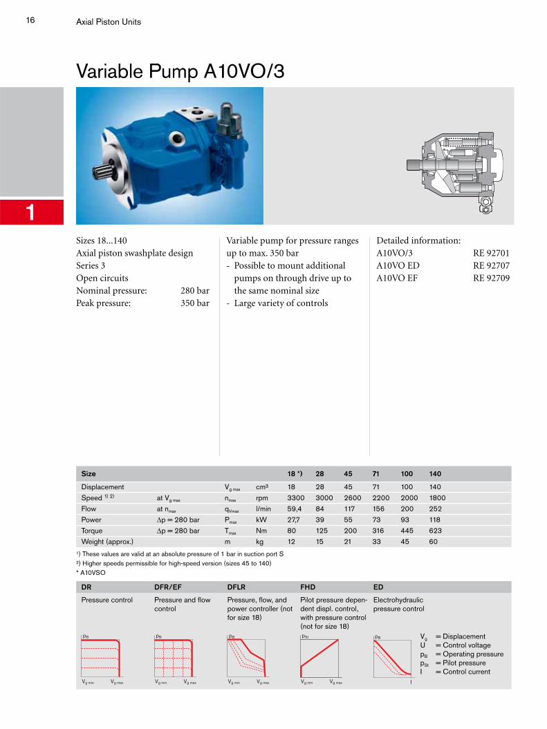
Variable Pump A10VO/3
1Sizes 18...140Axial piston swashplate designSeries 3Open circuitsNominal pressure: 280 barPeak pressure: 350 bar
Variable pump for pressure ranges up to max. 350 bar- Possible to mount additional
pumps on through drive up to the same nominal size
- Large variety of controls
Detailed information:A10VO/3 RE 92701A10VO ED RE 92707A10VO EF RE 92709
Size 18 *) 28 45 71 100 140
Displacement Vg max cm³ 18 28 45 71 100 140Speed 1) 2) at Vg max nmax rpm 3300 3000 2600 2200 2000 1800Flow at nmax qVmax l/min 59,4 84 117 156 200 252Power Δp = 280 bar Pmax kW 27,7 39 55 73 93 118Torque Δp = 280 bar Tmax Nm 80 125 200 316 445 623Weight (approx.) m kg 12 15 21 33 45 60
¹) These values are valid at an absolute pressure of 1 bar in suction port S²) Higher speeds permissible for high-speed version (sizes 45 to 140)* A10VSO
DR
Pressure control
pB
Vg maxVg min
DFR/EF
Pressure and flow control
pB
Vg maxVg min
DFLR
Pressure, flow, and power controller (not for size 18)
pB
Vg maxVg min
FHD
Pilot pressure depen-dent displ. control, with pressure control (not for size 18)pSt
Vg maxVg min
ED
Electrohydraulic pressure control
pB
I
Vg = DisplacementU = Control voltagepB = Operating pressurepSt = Pilot pressureI = Control current
17
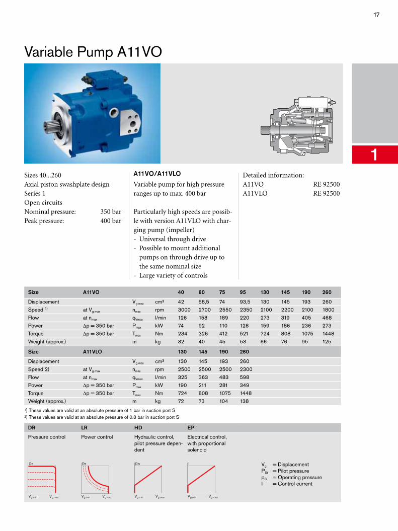
Variable Pump A11VO
1Sizes 40...260Axial piston swashplate designSeries 1Open circuitsNominal pressure: 350 barPeak pressure: 400 bar
A11VO/A11VLO
Variable pump for high pressure ranges up to max. 400 bar
Particularly high speeds are possib-le with version A11VLO with char-ging pump (impeller)- Universal through drive- Possible to mount additional
pumps on through drive up to the same nominal size
- Large variety of controls
Detailed information:A11VO RE 92500A11VLO RE 92500
Size A11VO 40 60 75 95 130 145 190 260
Displacement Vg max cm³ 42 58,5 74 93,5 130 145 193 260Speed 1) at Vg max nmax rpm 3000 2700 2550 2350 2100 2200 2100 1800Flow at nmax qVmax l/min 126 158 189 220 273 319 405 468Power Δp = 350 bar Pmax kW 74 92 110 128 159 186 236 273Torque Δp = 350 bar Tmax Nm 234 326 412 521 724 808 1075 1448Weight (approx.) m kg 32 40 45 53 66 76 95 125
Size A11VLO 130 145 190 260
Displacement Vg max cm³ 130 145 193 260Speed 2) at Vg max nmax rpm 2500 2500 2500 2300Flow at nmax qVmax l/min 325 363 483 598Power Δp = 350 bar Pmax kW 190 211 281 349Torque Δp = 350 bar Tmax Nm 724 808 1075 1448Weight (approx.) m kg 72 73 104 138
¹) These values are valid at an absolute pressure of 1 bar in suction port S²) These values are valid at an absolute pressure of 0.8 bar in suction port S
DR
Pressure control
pB
Vg maxVg min
LR
Power control
pB
Vg maxVg min
HD
Hydraulic control, pilot pressure depen-dent
pSt
Vg maxVg min
EP
Electrical control, with proportional solenoid
I
Vg maxVg min
Vg = DisplacementPSt = Pilot pressurepB = Operating pressureI = Control current
18 Axial Piston Units
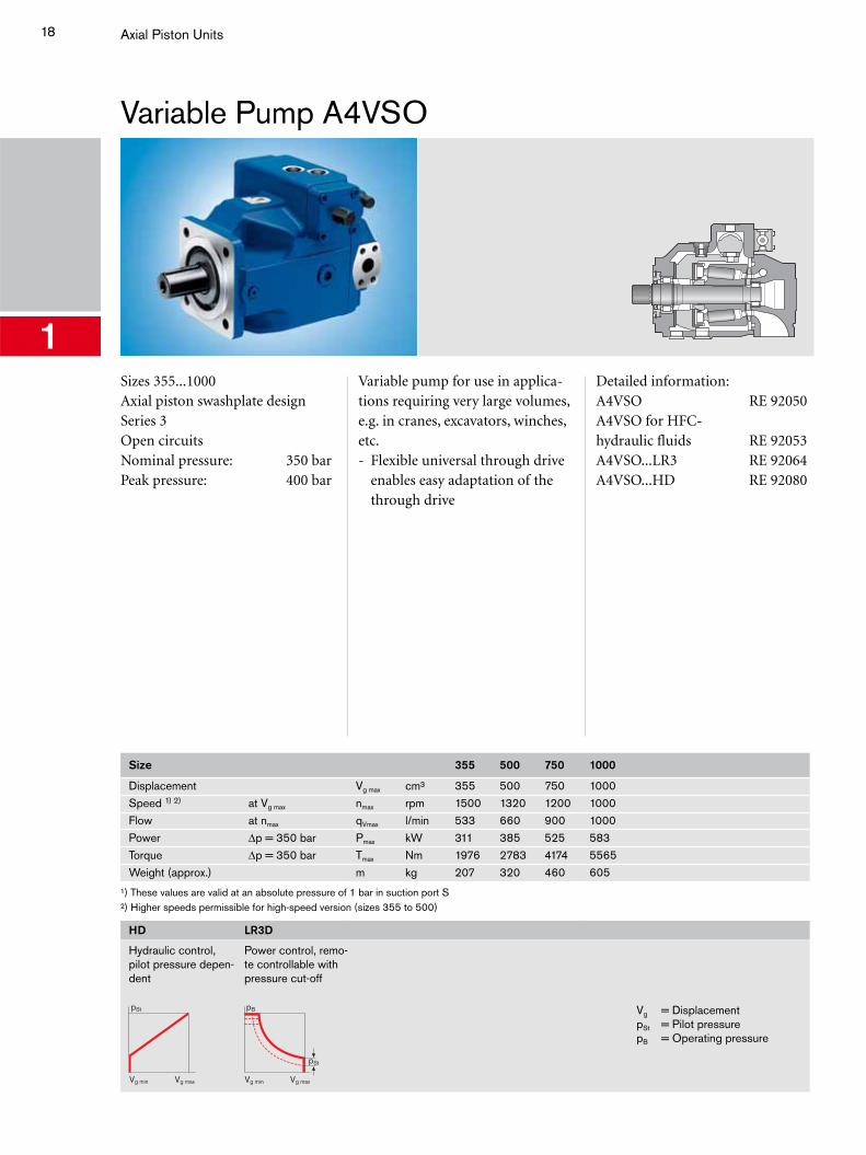
Variable Pump A4VSO
1Sizes 355...1000Axial piston swashplate designSeries 3Open circuitsNominal pressure: 350 barPeak pressure: 400 bar
Variable pump for use in applica-tions requiring very large volumes, e.g. in cranes, excavators, winches, etc.- Flexible universal through drive
enables easy adaptation of the through drive
Detailed information:A4VSO RE 92050A4VSO for HFC-hydraulic fluids RE 92053A4VSO...LR3 RE 92064A4VSO...HD RE 92080
Size 355 500 750 1000
Displacement Vg max cm³ 355 500 750 1000Speed 1) 2) at Vg max nmax rpm 1500 1320 1200 1000Flow at nmax qVmax l/min 533 660 900 1000Power Δp = 350 bar Pmax kW 311 385 525 583Torque Δp = 350 bar Tmax Nm 1976 2783 4174 5565Weight (approx.) m kg 207 320 460 605
¹) These values are valid at an absolute pressure of 1 bar in suction port S²) Higher speeds permissible for high-speed version (sizes 355 to 500)
HD
Hydraulic control, pilot pressure depen-dent
pSt
Vg maxVg min
LR3D
Power control, remo-te controllable with pressure cut-off
pB
pSt
Vg maxVg min
Vg = DisplacementpSt = Pilot pressurepB = Operating pressure
19
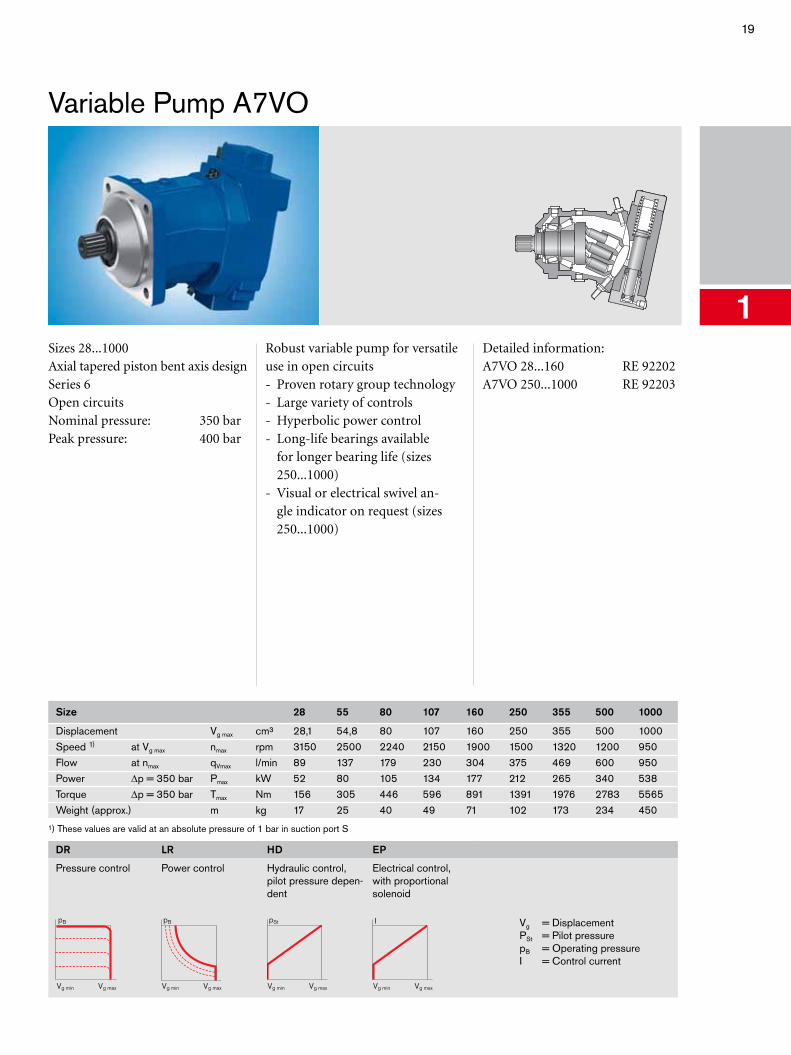
Variable Pump A7VO
1Sizes 28...1000Axial tapered piston bent axis designSeries 6Open circuitsNominal pressure: 350 barPeak pressure: 400 bar
Robust variable pump for versatile use in open circuits- Proven rotary group technology- Large variety of controls- Hyperbolic power control- Long-life bearings available
for longer bearing life (sizes 250...1000)
- Visual or electrical swivel an-gle indicator on request (sizes 250...1000)
Detailed information:A7VO 28...160 RE 92202A7VO 250...1000 RE 92203
Size 28 55 80 107 160 250 355 500 1000
Displacement Vg max cm³ 28,1 54,8 80 107 160 250 355 500 1000Speed 1) at Vg max nmax rpm 3150 2500 2240 2150 1900 1500 1320 1200 950Flow at nmax qVmax l/min 89 137 179 230 304 375 469 600 950Power Δp = 350 bar Pmax kW 52 80 105 134 177 212 265 340 538Torque Δp = 350 bar Tmax Nm 156 305 446 596 891 1391 1976 2783 5565Weight (approx.) m kg 17 25 40 49 71 102 173 234 450
¹) These values are valid at an absolute pressure of 1 bar in suction port S
DR
Pressure control
pB
Vg maxVg min
LR
Power control
pB
Vg maxVg min
HD
Hydraulic control, pilot pressure depen-dent
pSt
Vg maxVg min
EP
Electrical control, with proportional solenoid
I
Vg maxVg min
Vg = DisplacementPSt = Pilot pressurepB = Operating pressureI = Control current
20 Axial Piston Units
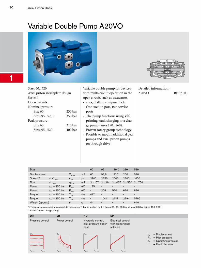
Variable Double Pump A20VO
1Sizes 60...520Axial piston swashplate designSeries 1Open circuitsNominal pressure Size 60: 250 bar Sizes 95...520: 350 barPeak pressure Size 60: 315 bar Sizes 95...520: 400 bar
Variable double pump for devices with multi-circuit operation in the open circuit, such as excavators, cranes, drilling equipment etc.- One suction port, two service
ports- The pump functions using self-
priming, tank charging or a char-ge pump (sizes 190...260).
- Proven rotary group technology- Possible to mount additional gear
pumps and axial piston pumps on through drive
Detailed information:A20VO RE 93100
Size 60 95 190 *) 260 *) 520
Displacement Vg max cm³ 60 93,8 192,7 260 520Speed 1) at Vg max nmax rpm 2700 2350 2500 2300 1450Flow at nmax qVmax l/min 2 x 157 2 x 214 2 x 467 2 x 580 2 x 754Power Δp = 250 bar Pmax kW 135 - - - -Power Δp = 350 bar Pmax kW - 258 560 696 880Torque Δp = 250 bar Tmax Nm 477 - - - -Torque Δp = 350 bar Tmax Nm - 1044 2145 2894 5796Weight (approx.) m kg 44 - - - 640
¹) These values are valid at an absolute pressure of 1 bar in suction port S (sizes 60, 95, 520) or at least 0.8 bar (sizes 190, 260)* A20VLO (with charge pump)
DR
Pressure control
pB
Vg maxVg min
LR
Power control
pB
Vg maxVg min
HD
Hydraulic control, pilot pressure depen-dent
pSt
Vg maxVg min
EP
Electrical control, with proportional solenoid
I
Vg maxVg min
Vg = DisplacementPSt = Pilot pressurepB = Operating pressureI = Control current
21
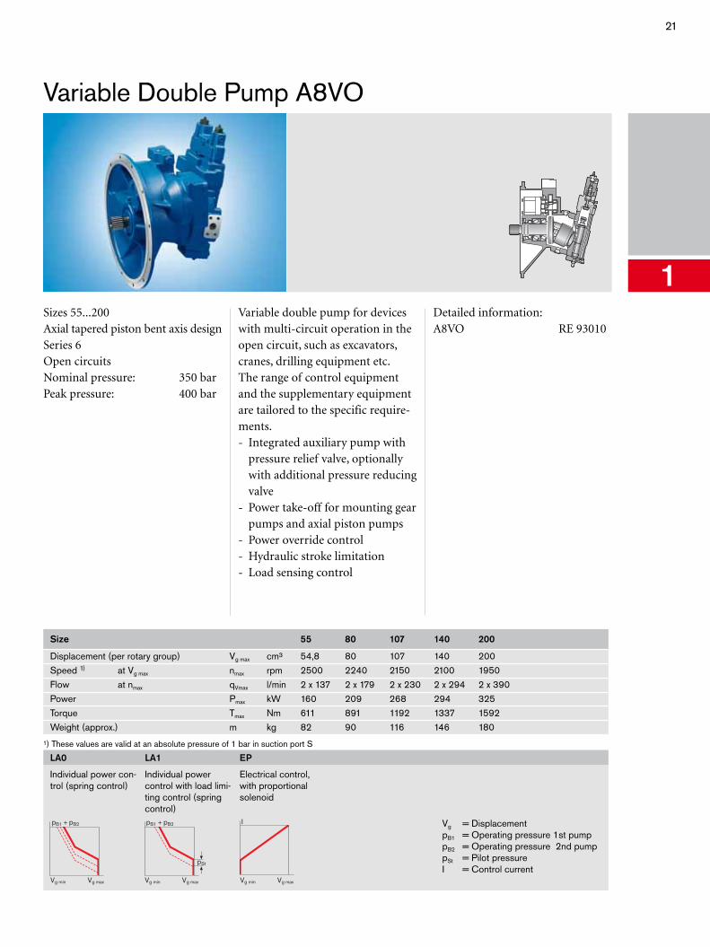
Variable Double Pump A8VO
1Sizes 55...200Axial tapered piston bent axis designSeries 6Open circuitsNominal pressure: 350 barPeak pressure: 400 bar
Variable double pump for devices with multi-circuit operation in the open circuit, such as excavators, cranes, drilling equipment etc.The range of control equipment and the supplementary equipment are tailored to the specific require-ments.- Integrated auxiliary pump with
pressure relief valve, optionally with additional pressure reducing valve
- Power take-off for mounting gear pumps and axial piston pumps
- Power override control- Hydraulic stroke limitation- Load sensing control
Detailed information:A8VO RE 93010
Size 55 80 107 140 200
Displacement (per rotary group) Vg max cm³ 54,8 80 107 140 200Speed 1) at Vg max nmax rpm 2500 2240 2150 2100 1950Flow at nmax qVmax l/min 2 x 137 2 x 179 2 x 230 2 x 294 2 x 390Power Pmax kW 160 209 268 294 325Torque Tmax Nm 611 891 1192 1337 1592Weight (approx.) m kg 82 90 116 146 180
¹) These values are valid at an absolute pressure of 1 bar in suction port S
LA0
Individual power con-trol (spring control)
Vg maxVg min
pB1 + pB2
LA1
Individual power control with load limi-ting control (spring control)
pSt
Vg maxVg min
pB1 + pB2
EP
Electrical control, with proportional solenoid
I
Vg maxVg min
Vg = DisplacementpB1 = Operating pressure 1st pumppB2 = Operating pressure 2nd pumppSt = Pilot pressureI = Control current
22 Axial Piston Units
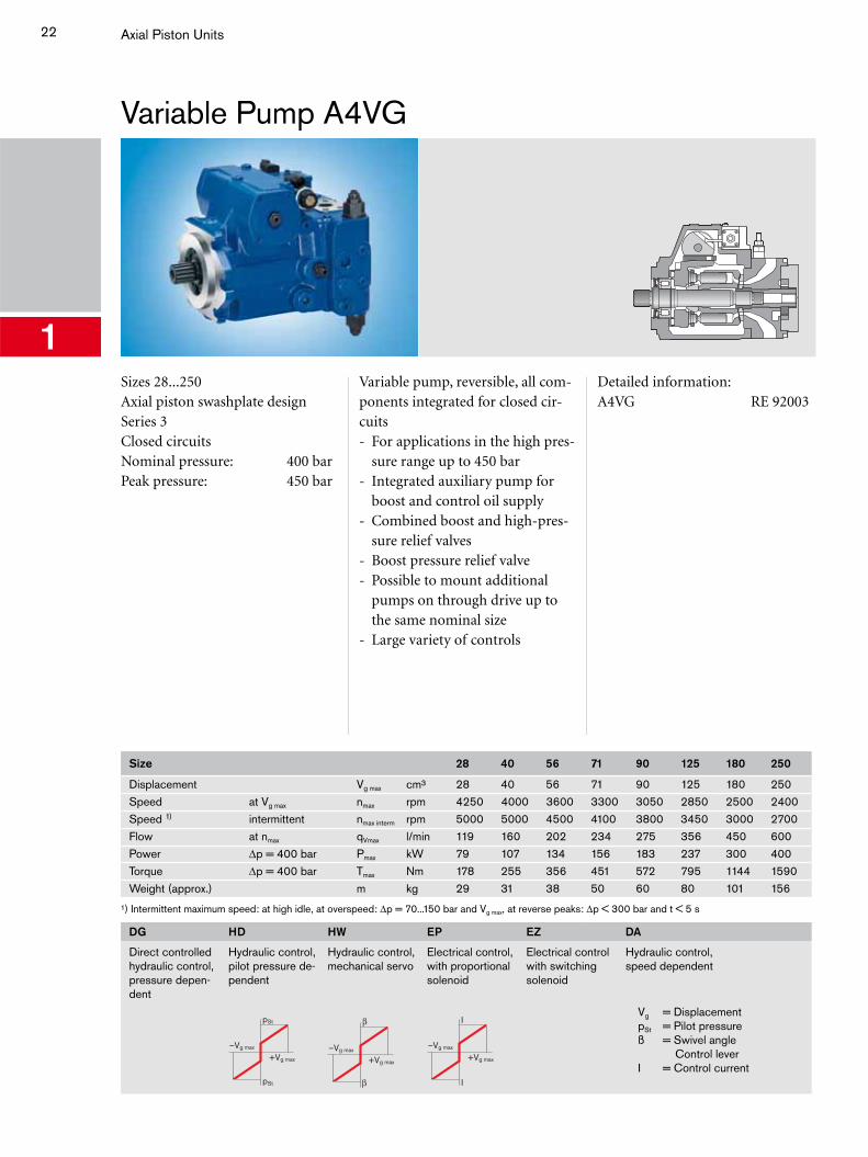
Variable Pump A4VG
1Sizes 28...250Axial piston swashplate designSeries 3Closed circuitsNominal pressure: 400 barPeak pressure: 450 bar
Variable pump, reversible, all com-ponents integrated for closed cir-cuits- For applications in the high pres-
sure range up to 450 bar- Integrated auxiliary pump for
boost and control oil supply- Combined boost and high-pres-
sure relief valves- Boost pressure relief valve- Possible to mount additional
pumps on through drive up to the same nominal size
- Large variety of controls
Detailed information:A4VG RE 92003
Size 28 40 56 71 90 125 180 250
Displacement Vg max cm³ 28 40 56 71 90 125 180 250Speed at Vg max nmax rpm 4250 4000 3600 3300 3050 2850 2500 2400Speed 1) intermittent nmax interm rpm 5000 5000 4500 4100 3800 3450 3000 2700Flow at nmax qVmax l/min 119 160 202 234 275 356 450 600Power Δp = 400 bar Pmax kW 79 107 134 156 183 237 300 400Torque Δp = 400 bar Tmax Nm 178 255 356 451 572 795 1144 1590Weight (approx.) m kg 29 31 38 50 60 80 101 156
¹) Intermittent maximum speed: at high idle, at overspeed: Δp = 70...150 bar and Vg max, at reverse peaks: Δp < 300 bar and t < 5 s
DG
Direct controlled hydraulic control, pressure depen-dent
HD
Hydraulic control, pilot pressure de-pendent
–Vg max
+Vg max
pSt
pSt
HW
Hydraulic control, mechanical servo
–Vg max
+Vg max
EP
Electrical control, with proportional solenoid
–Vg max
+Vg max
I
I
EZ
Electrical control with switching solenoid
DA
Hydraulic control, speed dependent
Vg = DisplacementpSt = Pilot pressureß = Swivel angle
Control leverI = Control current
23
Variable Pump A10VG
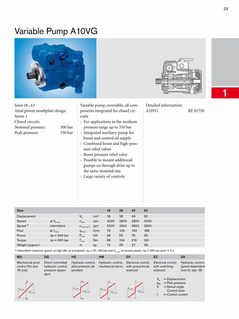
1Sizes 18...63Axial piston swashplate designSeries 1Closed circuitsNominal pressure: 300 barPeak pressure: 350 bar
Variable pump, reversible, all com-ponents integrated for closed cir-cuits- For applications in the medium
pressure range up to 350 bar- Integrated auxiliary pump for
boost and control oil supply- Combined boost and high-pres-
sure relief valves- Boost pressure relief valve- Possible to mount additional
pumps on through drive up to the same nominal size
- Large variety of controls
Detailed information:A10VG RE 92750
Size 18 28 45 63
Displacement Vg cm³ 18 28 46 63Speed at Vg max nmax rpm 4000 3900 3300 3000Speed 1) intermittent nmax interm rpm 5200 4500 3800 3500Flow at nmax qVmax l/min 72 109 152 189Power Δp = 300 bar Pmax kW 36 55 76 95Torque Δp = 300 bar Tmax Nm 86 134 219 301Weight (approx.) m kg 14 25 27 39
¹) Intermittent maximum speed: at high idle, at overspeed: Δp = 70...150 bar and Vg max, at reverse peaks: Δp < 300 bar and t < 5 s
MD
Mechanical pivot control (for size 18 only)
–Vg max
+Vg max
DG
Direct controlled hydraulic control, pressure depen-dent
HD
Hydraulic control, pilot pressure de-pendent
–Vg max
+Vg max
pSt
pSt
HW
Hydraulic control, mechanical servo
–Vg max
+Vg max
EP
Electrical control, with proportional solenoid
–Vg max
+Vg max
I
I
EZ
Electrical control with switching solenoid
DA
Hydraulic control, speed dependent (not for size 18)
Vg = DisplacementpSt = Pilot pressureß = Swivel angle
Control leverI = Control current
24 Axial Piston Units
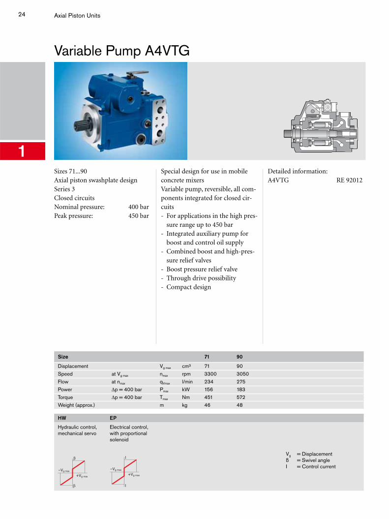
Variable Pump A4VTG
1Sizes 71...90Axial piston swashplate designSeries 3Closed circuitsNominal pressure: 400 barPeak pressure: 450 bar
Special design for use in mobile concrete mixersVariable pump, reversible, all com-ponents integrated for closed cir-cuits- For applications in the high pres-
sure range up to 450 bar- Integrated auxiliary pump for
boost and control oil supply- Combined boost and high-pres-
sure relief valves- Boost pressure relief valve- Through drive possibility- Compact design
Detailed information:A4VTG RE 92012
Size 71 90
Displacement Vg max cm³ 71 90Speed at Vg max nmax rpm 3300 3050Flow at nmax qVmax l/min 234 275Power Δp = 400 bar Pmax kW 156 183Torque Δp = 400 bar Tmax Nm 451 572Weight (approx.) m kg 46 48
HW
Hydraulic control, mechanical servo
–Vg max
+Vg max
EP
Electrical control, with proportional solenoid
–Vg max
+Vg max
I
I
Vg = Displacementß = Swivel angleI = Control current
25
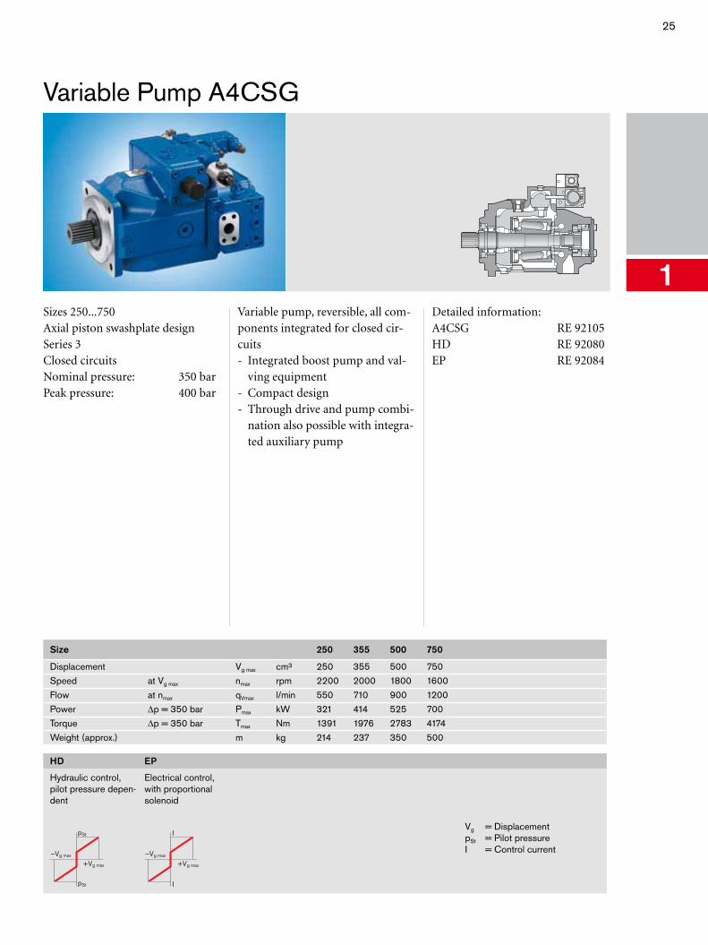
Variable Pump A4CSG
1Sizes 250...750Axial piston swashplate designSeries 3Closed circuitsNominal pressure: 350 barPeak pressure: 400 bar
Variable pump, reversible, all com-ponents integrated for closed cir-cuits- Integrated boost pump and val-
ving equipment- Compact design- Through drive and pump combi-
nation also possible with integra-ted auxiliary pump
Detailed information:A4CSG RE 92105HD RE 92080EP RE 92084
Size 250 355 500 750
Displacement Vg max cm³ 250 355 500 750Speed at Vg max nmax rpm 2200 2000 1800 1600Flow at nmax qVmax l/min 550 710 900 1200Power Δp = 350 bar Pmax kW 321 414 525 700Torque Δp = 350 bar Tmax Nm 1391 1976 2783 4174Weight (approx.) m kg 214 237 350 500
HD
Hydraulic control, pilot pressure depen-dent
–Vg max
+Vg max
pSt
pSt
EP
Electrical control, with proportional solenoid
–Vg max
+Vg max
I
I
Vg = DisplacementpSt = Pilot pressureI = Control current
26 Axial Piston Units
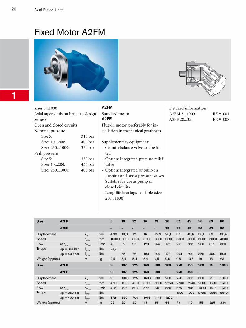
Fixed Motor A2FM
1Sizes 5...1000Axial tapered piston bent axis designSeries 6Open and closed circuitsNominal pressure Size 5: 315 bar Sizes 10...200: 400 bar Sizes 250...1000: 350 barPeak pressure Size 5: 350 bar Sizes 10...200: 450 bar Sizes 250...1000: 400 bar
A2FM
Standard motorA2FE
Plug-in motor, preferably for in-stallation in mechanical gearboxes
Supplementary equipment:- Counterbalance valve can be fit-
ted- Option: Integrated pressure relief
valve- Option: Integrated or built-on
flushing and boost pressure valves- Suitable for use as pump in
closed circuits- Long-life bearings available (sizes
250...1000)
Detailed information:A2FM 5...1000 RE 91001A2FE 28...355 RE 91008
Size A2FM 5 10 12 16 23 28 32 45 56 63 80
A2FE - - - - - 28 32 45 56 63 80
Displacement Vg cm³ 4,93 10,3 12 16 22,9 28,1 32 45,6 56,1 63 80,4Speed nmax rpm 10000 8000 8000 8000 6300 6300 6300 5600 5000 5000 4500Flow at nmax qVmax l/min 49 82 96 128 144 176 201 255 280 315 360Torque Δp = 315 bar Tmax Nm 24,7 - - - - - - - - - -
Δp = 400 bar Tmax Nm - 65 76 100 144 178 204 290 356 400 508Weight (approx.) m kg 2,5 5,4 5,4 5,4 9,5 9,5 9,5 13,5 18 18 23
Size A2FM 90 107 125 160 180 200 250 355 500 710 1000
A2FE 90 107 125 160 180 - 250 355 - - -
Displacement Vg cm³ 90 106,7 125 160,4 180 200 250 355 500 710 1000Speed nmax rpm 4500 4000 4000 3600 3600 2750 2700 2240 2000 1600 1600Flow at nmax qVmax l/min 405 427 500 577 648 550 675 795 1000 1136 1600Torque Δp = 350 bar Tmax Nm - - - - - - 1393 1978 2785 3955 5570
Δp = 400 bar Tmax Nm 572 680 796 1016 1144 1272 - - - - -Weight (approx.) m kg 23 32 32 45 45 66 73 110 155 325 336
27
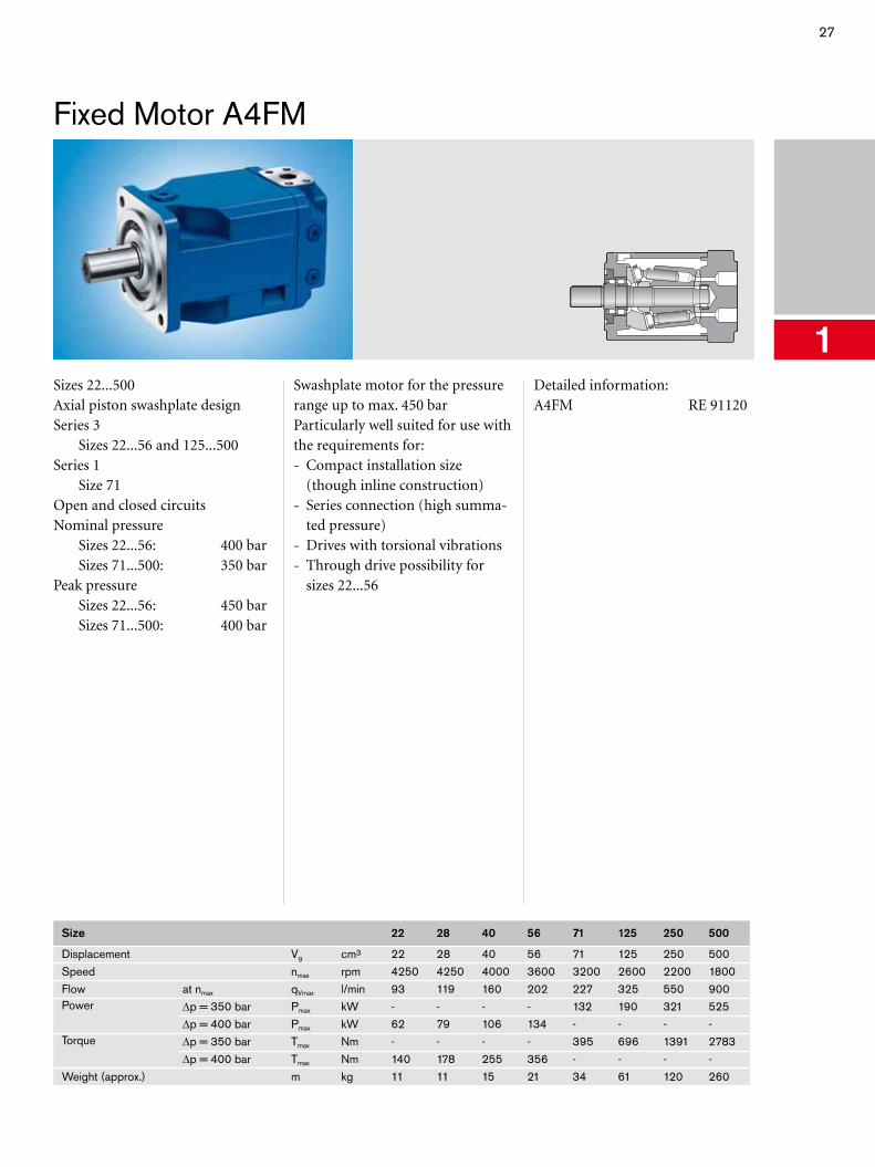
Fixed Motor A4FM
1Sizes 22...500Axial piston swashplate designSeries 3 Sizes 22...56 and 125...500Series 1 Size 71Open and closed circuitsNominal pressure Sizes 22...56: 400 bar Sizes 71...500: 350 barPeak pressure Sizes 22...56: 450 bar Sizes 71...500: 400 bar
Swashplate motor for the pressure range up to max. 450 barParticularly well suited for use with the requirements for:- Compact installation size
(though inline construction)- Series connection (high summa-
ted pressure)- Drives with torsional vibrations- Through drive possibility for
sizes 22...56
Detailed information:A4FM RE 91120
Size 22 28 40 56 71 125 250 500
Displacement Vg cm³ 22 28 40 56 71 125 250 500Speed nmax rpm 4250 4250 4000 3600 3200 2600 2200 1800Flow at nmax qVmax l/min 93 119 160 202 227 325 550 900Power Δp = 350 bar Pmax kW - - - - 132 190 321 525
Δp = 400 bar Pmax kW 62 79 106 134 - - - -Torque Δp = 350 bar Tmax Nm - - - - 395 696 1391 2783
Δp = 400 bar Tmax Nm 140 178 255 356 - - - -Weight (approx.) m kg 11 11 15 21 34 61 120 260
28 Axial Piston Units
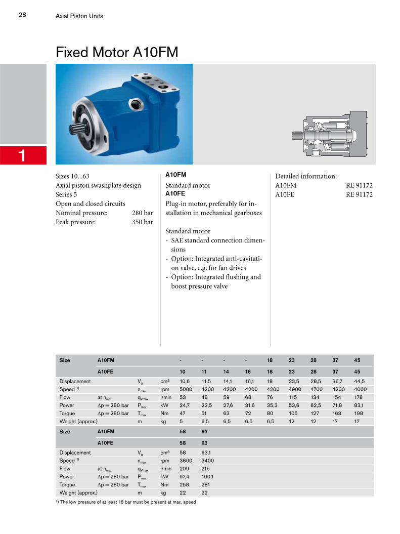
Fixed Motor A10FM
1Sizes 10...63Axial piston swashplate designSeries 5Open and closed circuitsNominal pressure: 280 barPeak pressure: 350 bar
A10FM
Standard motorA10FE
Plug-in motor, preferably for in-stallation in mechanical gearboxes
Standard motor- SAE standard connection dimen-
sions- Option: Integrated anti-cavitati-
on valve, e.g. for fan drives- Option: Integrated flushing and
boost pressure valve
Detailed information:A10FM RE 91172A10FE RE 91172
Size A10FM - - - - 18 23 28 37 45
A10FE 10 11 14 16 18 23 28 37 45
Displacement Vg cm³ 10,6 11,5 14,1 16,1 18 23,5 28,5 36,7 44,5Speed 1) nmax rpm 5000 4200 4200 4200 4200 4900 4700 4200 4000Flow at nmax qVmax l/min 53 48 59 68 76 115 134 154 178Power Δp = 280 bar Pmax kW 24,7 22,5 27,6 31,6 35,3 53,6 62,5 71,8 83,1Torque Δp = 280 bar Tmax Nm 47 51 63 72 80 105 127 163 198Weight (approx.) m kg 5 6,5 6,5 6,5 6,5 12 12 17 17
Size A10FM 58 63
A10FE 58 63
Displacement Vg cm³ 58 63,1Speed 1) nmax rpm 3600 3400Flow at nmax qVmax l/min 209 215Power Δp = 280 bar Pmax kW 97,4 100,1Torque Δp = 280 bar Tmax Nm 258 281Weight (approx.) m kg 22 22
¹) The low pressure of at least 18 bar must be present at max. speed
29
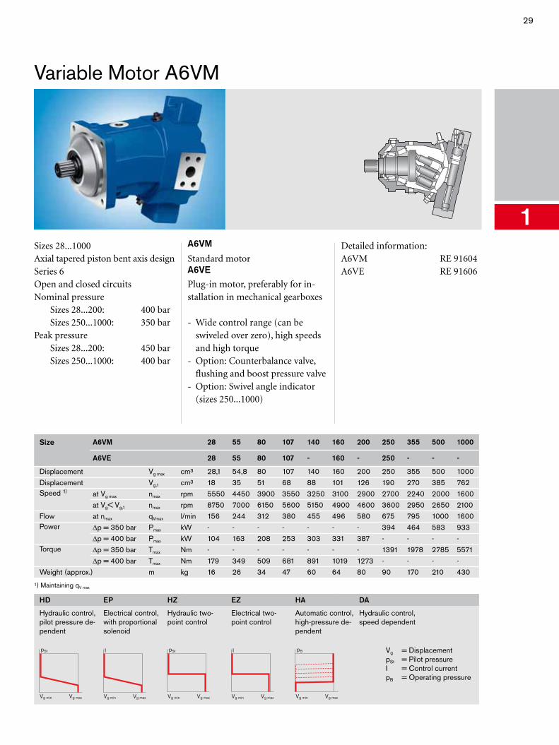
Variable Motor A6VM
1Sizes 28...1000Axial tapered piston bent axis designSeries 6Open and closed circuitsNominal pressure Sizes 28...200: 400 bar Sizes 250...1000: 350 barPeak pressure Sizes 28...200: 450 bar Sizes 250...1000: 400 bar
A6VM
Standard motorA6VE
Plug-in motor, preferably for in-stallation in mechanical gearboxes
- Wide control range (can be swiveled over zero), high speeds and high torque
- Option: Counterbalance valve, flushing and boost pressure valve
- Option: Swivel angle indicator (sizes 250...1000)
Detailed information:A6VM RE 91604A6VE RE 91606
Size A6VM 28 55 80 107 140 160 200 250 355 500 1000
A6VE 28 55 80 107 - 160 - 250 - - -
Displacement Vg max cm³ 28,1 54,8 80 107 140 160 200 250 355 500 1000Displacement Vg,1 cm³ 18 35 51 68 88 101 126 190 270 385 762Speed 1) at Vg max nmax rpm 5550 4450 3900 3550 3250 3100 2900 2700 2240 2000 1600
at Vg< Vg,1 nmax rpm 8750 7000 6150 5600 5150 4900 4600 3600 2950 2650 2100Flow at nmax qVmax l/min 156 244 312 380 455 496 580 675 795 1000 1600Power Δp = 350 bar Pmax kW - - - - - - - 394 464 583 933
Δp = 400 bar Pmax kW 104 163 208 253 303 331 387 - - - -Torque Δp = 350 bar Tmax Nm - - - - - - - 1391 1978 2785 5571
Δp = 400 bar Tmax Nm 179 349 509 681 891 1019 1273 - - - -Weight (approx.) m kg 16 26 34 47 60 64 80 90 170 210 430
¹) Maintaining qV max
HD
Hydraulic control, pilot pressure de-pendent
pSt
Vg maxVg min
EP
Electrical control, with proportional solenoid
I
Vg maxVg min
HZ
Hydraulic two-point control
Vg maxVg min
pSt
EZ
Electrical two-point control
I
Vg maxVg min
HA
Automatic control, high-pressure de-pendent
pB
Vg maxVg min
DA
Hydraulic control, speed dependent
Vg = DisplacementpSt = Pilot pressureI = Control currentpB = Operating pressure
30 Axial Piston Units
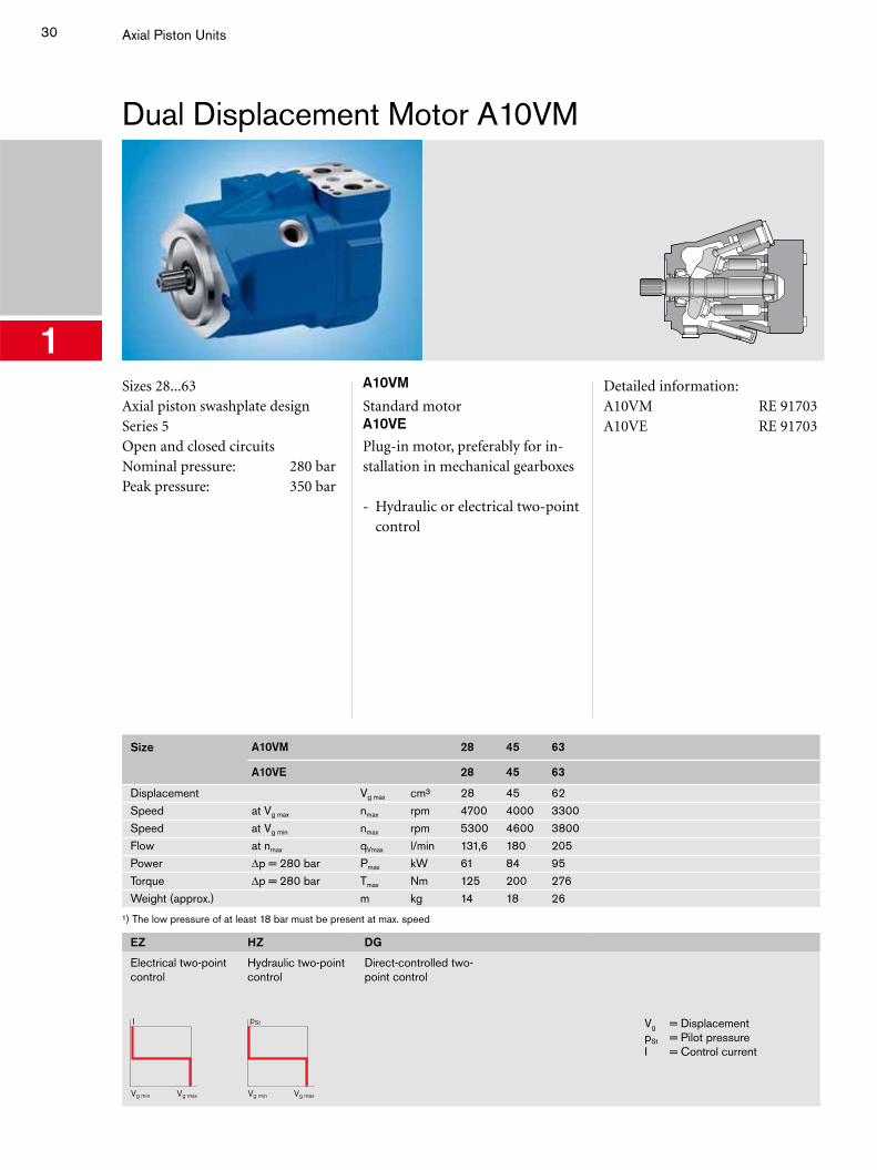
Dual Displacement Motor A10VM
1Sizes 28...63Axial piston swashplate designSeries 5Open and closed circuitsNominal pressure: 280 barPeak pressure: 350 bar
A10VM
Standard motorA10VE
Plug-in motor, preferably for in-stallation in mechanical gearboxes
- Hydraulic or electrical two-point control
Detailed information:A10VM RE 91703A10VE RE 91703
Size A10VM 28 45 63
A10VE 28 45 63
Displacement Vg max cm³ 28 45 62Speed at Vg max nmax rpm 4700 4000 3300Speed at Vg min nmax rpm 5300 4600 3800Flow at nmax qVmax l/min 131,6 180 205Power Δp = 280 bar Pmax kW 61 84 95Torque Δp = 280 bar Tmax Nm 125 200 276Weight (approx.) m kg 14 18 26
¹) The low pressure of at least 18 bar must be present at max. speed
EZ
Electrical two-point control
I
Vg maxVg min
HZ
Hydraulic two-point control
Vg maxVg min
pSt
DG
Direct-controlled two-point control
Vg = DisplacementpSt = Pilot pressureI = Control current
31
External Gear Units
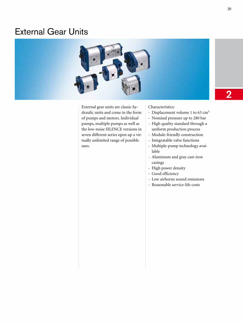
2External gear units are classic hy-draulic units and come in the form of pumps and motors. Individual pumps, multiple pumps as well as the low-noise SILENCE versions in seven different series open up a vir-tually unlimited range of possible uses.
Characteristics:- Displacement volume 1 to 63 cm3
- Nominal pressure up to 280 bar- High quality standard through a
uniform production process- Module-friendly construction- Integratable valve functions- Multiple-pump technology avai-
lable- Aluminum and gray cast-iron
casings- High power density- Good efficiency- Low airborne sound emissions- Reasonable service-life costs
32 External Gear Units
External Gear Pumps, Standard Version
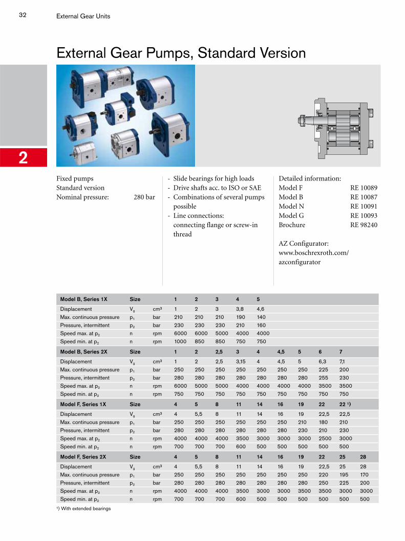
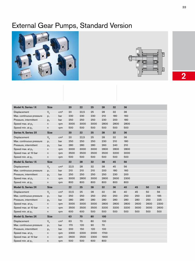
2Fixed pumpsStandard versionNominal pressure: 280 bar
- Slide bearings for high loads- Drive shafts acc. to ISO or SAE- Combinations of several pumps
possible- Line connections:
connecting flange or screw-in thread
Detailed information:Model F RE 10089Model B RE 10087Model N RE 10091Model G RE 10093Brochure RE 98240
AZ Configurator: www.boschrexroth.com/azconfigurator
Model B, Series 1X Size 1 2 3 4 5
Displacement Vg cm³ 1 2 3 3,8 4,6Max. continuous pressure p1 bar 210 210 210 190 140Pressure, intermittent p2 bar 230 230 230 210 160Speed max. at p2 n rpm 6000 6000 5000 4000 4000Speed min. at p2 n rpm 1000 850 850 750 750
Model B, Series 2X Size 1 2 2,5 3 4 4,5 5 6 7
Displacement Vg cm³ 1 2 2,5 3,15 4 4,5 5 6,3 7,1Max. continuous pressure p1 bar 250 250 250 250 250 250 250 225 200Pressure, intermittent p2 bar 280 280 280 280 280 280 280 255 230Speed max. at p2 n rpm 6000 5000 5000 4000 4000 4000 4000 3500 3500Speed min. at p2 n rpm 750 750 750 750 750 750 750 750 750
Model F, Series 1X Size 4 5 8 11 14 16 19 22 22 ¹)
Displacement Vg cm³ 4 5,5 8 11 14 16 19 22,5 22,5Max. continuous pressure p1 bar 250 250 250 250 250 250 210 180 210Pressure, intermittent p2 bar 280 280 280 280 280 280 230 210 230Speed max. at p2 n rpm 4000 4000 4000 3500 3000 3000 3000 2500 3000Speed min. at p2 n rpm 700 700 700 600 500 500 500 500 500
Model F, Series 2X Size 4 5 8 11 14 16 19 22 25 28
Displacement Vg cm³ 4 5,5 8 11 14 16 19 22,5 25 28Max. continuous pressure p1 bar 250 250 250 250 250 250 250 220 195 170Pressure, intermittent p2 bar 280 280 280 280 280 280 280 250 225 200Speed max. at p2 n rpm 4000 4000 4000 3500 3000 3000 3500 3500 3000 3000Speed min. at p2 n rpm 700 700 700 600 500 500 500 500 500 500
¹) With extended bearings
33
External Gear Pumps, Standard Version
2
Model N, Series 1X Size 20 22 25 28 32 36
Displacement Vg cm³ 20 22,5 25 28 32 36Max. continuous pressure p1 bar 230 230 230 210 180 160Pressure, intermittent p2 bar 250 250 250 230 200 180Speed max. at p2 n rpm 3000 3000 3000 2800 2800 2800Speed min. at p2 n rpm 500 500 500 500 500 500
Series N, Series 2X Size 20 22 25 28 32 36
Displacement Vg cm³ 20 22,5 25 28 32 36Max. continuous pressure p1 bar 250 250 250 230 210 180Pressure, intermittent p2 bar 280 280 280 260 240 210Speed max. at p2 n rpm 3000 3000 3000 2800 2800 2800Speed max. at 10 bar n rpm 3500 3500 3500 3500 3200 3000Speed min. at p2 n rpm 500 500 500 500 500 500
Model G, Series 1X Size 22 28 32 38 45 56
Displacement Vg cm³ 22,5 28 32 38 45 56Max. continuous pressure p1 bar 210 210 210 200 180 160Pressure, intermittent p2 bar 250 250 250 250 230 200Speed max. at p2 n rpm 3000 2800 3000 2800 2600 2300Speed min. at p2 n rpm 800 800 800 800 800 800
Model G, Series 2X Size 22 25 28 32 36 40 45 50 56
Displacement Vg cm³ 22,5 25 28 32 36 40 45 50 56Max. continuous pressure p1 bar 250 250 250 250 250 250 250 220 195Pressure, intermittent p2 bar 280 280 280 280 280 280 280 250 225Speed max. at p2 n rpm 3000 3000 3000 2800 2800 2800 2600 2600 2300Speed max. at 10 bar n rpm 3500 3500 3500 3200 3200 3200 3000 3000 2600Speed min. at p2 n rpm 600 600 500 500 500 500 500 500 500
Model G, Series 2X Size 63 70 80 100
Displacement Vg cm³ 63 70 80 100Max. continuous pressure p1 bar 170 120 90 70Pressure, intermittent p2 bar 200 150 120 100Speed max. at p2 n rpm 2300 2200 2000 1700Speed max. at 10 bar n rpm 2600 2500 2300 1900Speed min. at p2 n rpm 500 500 600 800
34 External Gear Units
External Gear Pumps, SILENCE Version
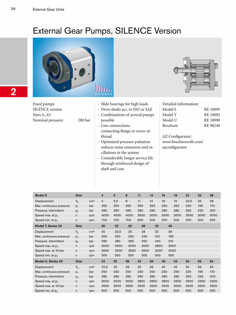
2Fixed pumpsSILENCE versionSizes 4...63Nominal pressure: 280 bar
- Slide bearings for high loads- Drive shafts acc. to ISO or SAE- Combinations of several pumps
possible- Line connections:
connecting flange or screw-in thread
- Optimized pressure pulsation reduces noise emissions and os-cillations in the system
- Considerably longer service life through reinforced design of shaft and case
Detailed information:Model S RE 10095Model T RE 10092Model U RE 10098Brochure RE 98240
AZ Configurator: www.boschrexroth.com/azconfigurator
Model S Size 4 5 8 11 14 16 19 22 25 28
Displacement Vg cm³ 4 5,5 8 11 14 16 19 22,5 25 28Max. continuous pressure p1 bar 250 250 250 250 250 250 250 220 195 170Pressure, intermittent p2 bar 280 280 280 280 280 280 280 250 225 200Speed max. at p2 n rpm 4000 4000 4000 3500 3000 3000 3500 3500 3000 3000Speed min. at p2 n rpm 700 700 700 600 500 500 500 500 500 500
Model T, Series 2X Size 20 22 25 28 32 36
Displacement Vg cm³ 20 22,5 25 28 32 36Max. continuous pressure p1 bar 250 250 250 230 210 180Pressure, intermittent p2 bar 280 280 280 260 240 210Speed max. at p2 n rpm 3000 3000 3000 3000 2800 2600Speed max. at 10 bar n rpm 3500 3500 3500 3500 3200 3000Speed min. at p2 n rpm 500 500 500 500 500 500
Model U, Series 2X Size 22 25 28 32 36 40 45 50 56 63
Displacement Vg cm³ 22,5 25 28 32 36 40 45 50 56 63Max. continuous pressure p1 bar 250 250 250 250 250 250 250 220 195 170Pressure, intermittent p2 bar 280 280 280 280 280 280 280 250 225 200Speed max. at p2 n rpm 3000 3000 3000 2800 2800 2800 2600 2600 2300 2300Speed max. at 10 bar n rpm 3500 3500 3500 3200 3200 3200 3000 3000 2600 2600Speed min. at p2 n rpm 600 600 500 500 500 500 500 500 500 500
35
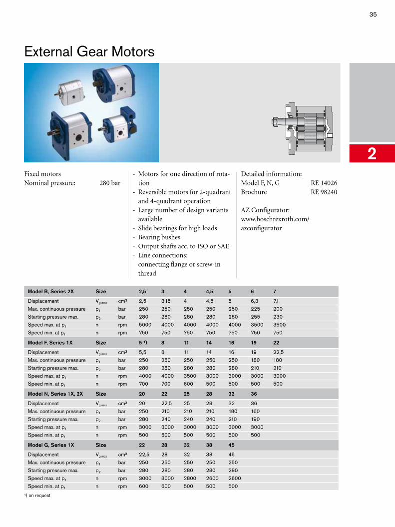
External Gear Motors
2Fixed motorsNominal pressure: 280 bar
- Motors for one direction of rota-tion
- Reversible motors for 2-quadrant and 4-quadrant operation
- Large number of design variants available
- Slide bearings for high loads- Bearing bushes- Output shafts acc. to ISO or SAE- Line connections:
connecting flange or screw-in thread
Detailed information:Model F, N, G RE 14026Brochure RE 98240
AZ Configurator: www.boschrexroth.com/azconfigurator
Model B, Series 2X Size 2,5 3 4 4,5 5 6 7
Displacement Vg max cm³ 2,5 3,15 4 4,5 5 6,3 7,1Max. continuous pressure p1 bar 250 250 250 250 250 225 200Starting pressure max. p2 bar 280 280 280 280 280 255 230Speed max. at p1 n rpm 5000 4000 4000 4000 4000 3500 3500Speed min. at p1 n rpm 750 750 750 750 750 750 750
Model F, Series 1X Size 5 ¹) 8 11 14 16 19 22
Displacement Vg max cm³ 5,5 8 11 14 16 19 22,5Max. continuous pressure p1 bar 250 250 250 250 250 180 180Starting pressure max. p2 bar 280 280 280 280 280 210 210Speed max. at p1 n rpm 4000 4000 3500 3000 3000 3000 3000Speed min. at p1 n rpm 700 700 600 500 500 500 500
Model N, Series 1X, 2X Size 20 22 25 28 32 36
Displacement Vg max cm³ 20 22,5 25 28 32 36Max. continuous pressure p1 bar 250 210 210 210 180 160Starting pressure max. p2 bar 280 240 240 240 210 190Speed max. at p1 n rpm 3000 3000 3000 3000 3000 3000Speed min. at p1 n rpm 500 500 500 500 500 500
Model G, Series 1X Size 22 28 32 38 45
Displacement Vg max cm³ 22,5 28 32 38 45Max. continuous pressure p1 bar 250 250 250 250 250Starting pressure max. p2 bar 280 280 280 280 280Speed max. at p1 n rpm 3000 3000 2800 2600 2600Speed min. at p1 n rpm 600 600 500 500 500
¹) on request
36 External Gear Units
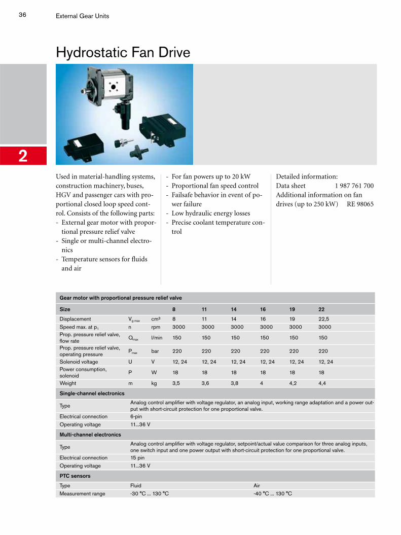
Hydrostatic Fan Drive
2Used in material-handling systems, construction machinery, buses, HGV and passenger cars with pro-portional closed loop speed cont-rol. Consists of the following parts: - External gear motor with propor-
tional pressure relief valve- Single or multi-channel electro-
nics - Temperature sensors for fluids
and air
- For fan powers up to 20 kW- Proportional fan speed control- Failsafe behavior in event of po-
wer failure- Low hydraulic energy losses- Precise coolant temperature con-
trol
Detailed information:Data sheet 1 987 761 700Additional information on fan drives (up to 250 kW) RE 98065
Gear motor with proportional pressure relief valve
Size 8 11 14 16 19 22
Displacement Vg max cm³ 8 11 14 16 19 22,5Speed max. at p1 n rpm 3000 3000 3000 3000 3000 3000Prop. pressure relief valve, flow rate
Qmax l/min 150 150 150 150 150 150
Prop. pressure relief valve, operating pressure
Pmax bar 220 220 220 220 220 220
Solenoid voltage U V 12, 24 12, 24 12, 24 12, 24 12, 24 12, 24Power consumption, solenoid
P W 18 18 18 18 18 18
Weight m kg 3,5 3,6 3,8 4 4,2 4,4
Single-channel electronics
TypeAnalog control amplifier with voltage regulator, an analog input, working range adaptation and a power out-put with short-circuit protection for one proportional valve.
Electrical connection 6-pinOperating voltage 11...36 V
Multi-channel electronics
TypeAnalog control amplifier with voltage regulator, setpoint/actual value comparison for three analog inputs, one switch input and one power output with short-circuit protection for one proportional valve.
Electrical connection 15 pinOperating voltage 11...36 V
PTC sensors
Type Fluid AirMeasurement range -30 °C ... 130 °C -40 °C ... 130 °C
37
Radial Piston Motors
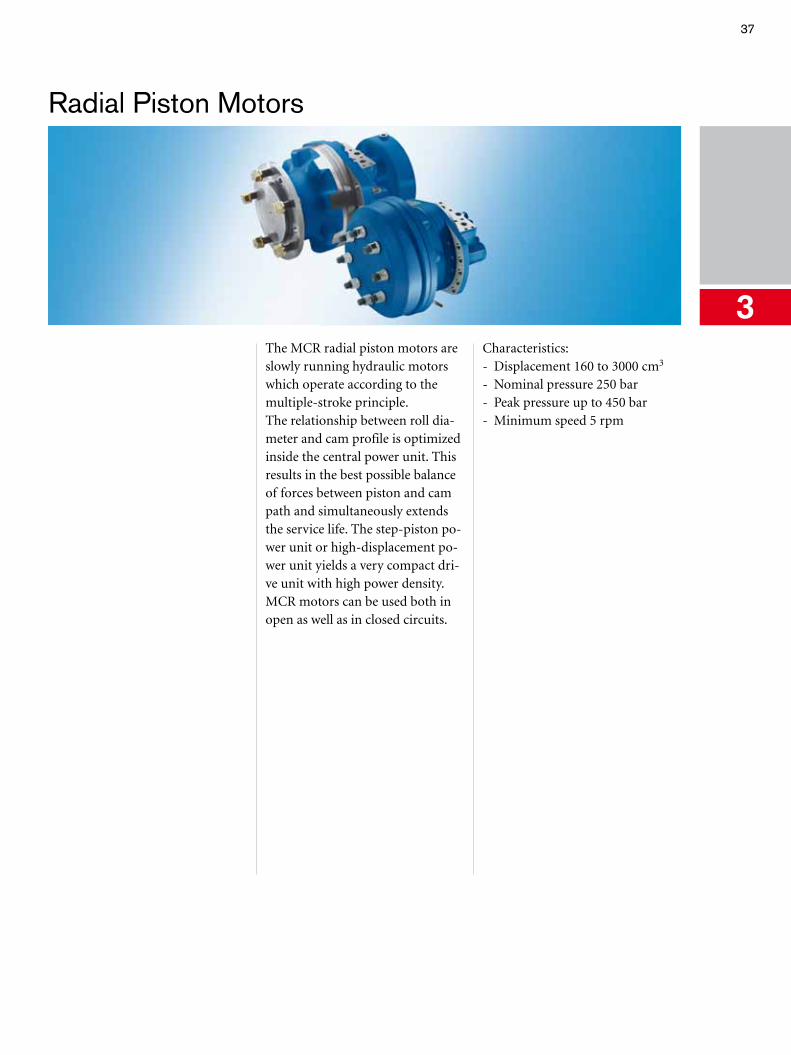
3The MCR radial piston motors are slowly running hydraulic motors which operate according to the multiple-stroke principle.The relationship between roll dia-meter and cam profile is optimized inside the central power unit. This results in the best possible balance of forces between piston and cam path and simultaneously extends the service life. The step-piston po-wer unit or high-displacement po-wer unit yields a very compact dri-ve unit with high power density.MCR motors can be used both in open as well as in closed circuits.
Characteristics: - Displacement 160 to 3000 cm3
- Nominal pressure 250 bar - Peak pressure up to 450 bar - Minimum speed 5 rpm
38 Radial Piston Motors
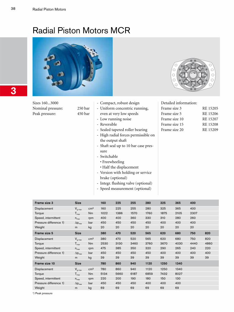
Radial Piston Motors MCR
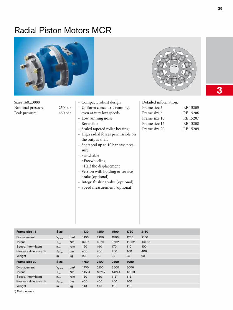
3Sizes 160...3000Nominal pressure: 250 barPeak pressure: 450 bar
- Compact, robust design- Uniform concentric running,
even at very low speeds- Low running noise- Reversible- Sealed tapered roller bearing- High radial forces permissible on
the output shaft- Shaft seal up to 10 bar case pres-
sure- Switchable
• Freewheeling • Half the displacement
- Version with holding or service brake (optional)
- Integr. flushing valve (optional)- Speed measurement (optional)
Detailed information:Frame size 3 RE 15205Frame size 5 RE 15206Frame size 10 RE 15207Frame size 15 RE 15208Frame size 20 RE 15209
Frame size 3 Size 160 225 255 280 325 365 400
Displacement Vg max cm³ 160 225 255 280 325 365 400Torque Tmax Nm 1022 1386 1570 1760 1875 2105 2307Speed, intermittent nmax rpm 400 400 360 330 310 280 260Pressure difference 1) Δpmax bar 450 450 450 450 400 400 400Weight m kg 20 20 20 20 20 20 20
Frame size 5 Size 380 470 520 565 620 680 750 820
Displacement Vg max cm³ 380 470 520 565 620 680 750 820Torque Tmax Nm 2530 3130 3460 3760 3670 4030 4440 4860Speed, intermittent nmax rpm 475 385 350 320 290 265 240 220Pressure difference 1) Δpmax bar 450 450 450 450 400 400 400 400Weight m kg 39 39 39 39 39 39 39 39
Frame size 10 Size 780 860 940 1120 1250 1340
Displacement Vg max cm³ 780 860 940 1120 1250 1340Torque Tmax Nm 5134 5660 6187 6859 7432 8027Speed, intermittent nmax rpm 220 200 190 180 150 130Pressure difference 1) Δpmax bar 450 450 450 400 400 400Weight m kg 69 69 69 69 69 69
¹) Peak pressure
39
Radial Piston Motors MCR
3Sizes 160...3000Nominal pressure: 250 barPeak pressure: 450 bar
- Compact, robust design- Uniform concentric running,
even at very low speeds- Low running noise- Reversible- Sealed tapered roller bearing- High radial forces permissible on
the output shaft- Shaft seal up to 10 bar case pres-
sure- Switchable
• Freewheeling • Half the displacement
- Version with holding or service brake (optional)
- Integr. flushing valve (optional)- Speed measurement (optional)
Detailed information:Frame size 3 RE 15205Frame size 5 RE 15206Frame size 10 RE 15207Frame size 15 RE 15208Frame size 20 RE 15209
Frame size 15 Size 1130 1250 1500 1780 2150
Displacement Vg max cm³ 1130 1250 1500 1780 2150Torque Tmax Nm 8095 8955 9552 11332 13688Speed, intermittent nmax rpm 190 190 170 110 100Pressure difference 1) Δpmax bar 450 450 450 400 400Weight m kg 93 93 93 93 93
Frame size 20 Size 1750 2100 2500 3000
Displacement Vg max cm³ 1750 2100 2500 3000Torque Tmax Nm 11531 13762 14244 17073Speed, intermittent nmax rpm 160 160 115 115Pressure difference 1) Δpmax bar 450 450 400 400Weight m kg 110 110 110 110
¹) Peak pressure

40
3
41
Mobile Controls
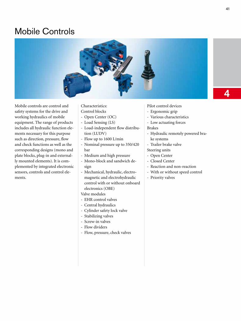
4Mobile controls are control and safety systems for the drive and working hydraulics of mobile equipment. The range of products includes all hydraulic function ele-ments necessary for this purpose such as direction, pressure, flow and check functions as well as the corresponding designs (mono and plate blocks, plug-in and external-ly mounted elements). It is com-plemented by integrated electronic sensors, controls and control ele-ments.
Characteristics:Control blocks - Open Center (OC) - Load Sensing (LS) - Load-independent flow distribu-
tion (LUDV) - Flow up to 1600 L/min - Nominal pressure up to 350/420
bar - Medium and high pressure - Mono-block and sandwich de-
sign - Mechanical, hydraulic, electro-
magnetic and electrohydraulic control with or without onboard electronics (OBE)
Valve modules - EHR control valves - Central hydraulics - Cylinder safety lock valve - Stabilizing valves - Screw-in valves - Flow dividers - Flow, pressure, check valves
Pilot control devices- Ergonomic grip- Various characteristics- Low actuating forcesBrakes- Hydraulic remotely powered bra-
ke systems- Trailer brake valveSteering units- Open Center- Closed Center- Reaction and non-reaction- With or without speed control- Priority valves
42 Mobile Controls
Open Center Control Block SM
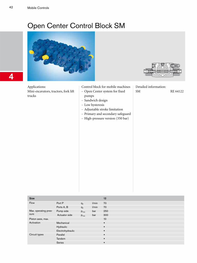
4Applications:Mini-excavators, tractors, fork lift trucks
Control block for mobile machines- Open Center system for fixed
pumps- Sandwich design- Low hysteresis- Adjustable stroke limitation- Primary and secondary safeguard- High-pressure version (350 bar)
Detailed information:SM RE 64122
Size 12
Flow Port P qV l/min 70Ports A, B qV l/min 70
Max. operating pres-sure
Pump side pmax bar 250 Actuator side pmax bar 300
Piston axes, max. 10Activation Mechanical
Hydraulic
Electrohydraulic Circuit types Parallel
Tandem
Series
43
Open Center Control Block MO
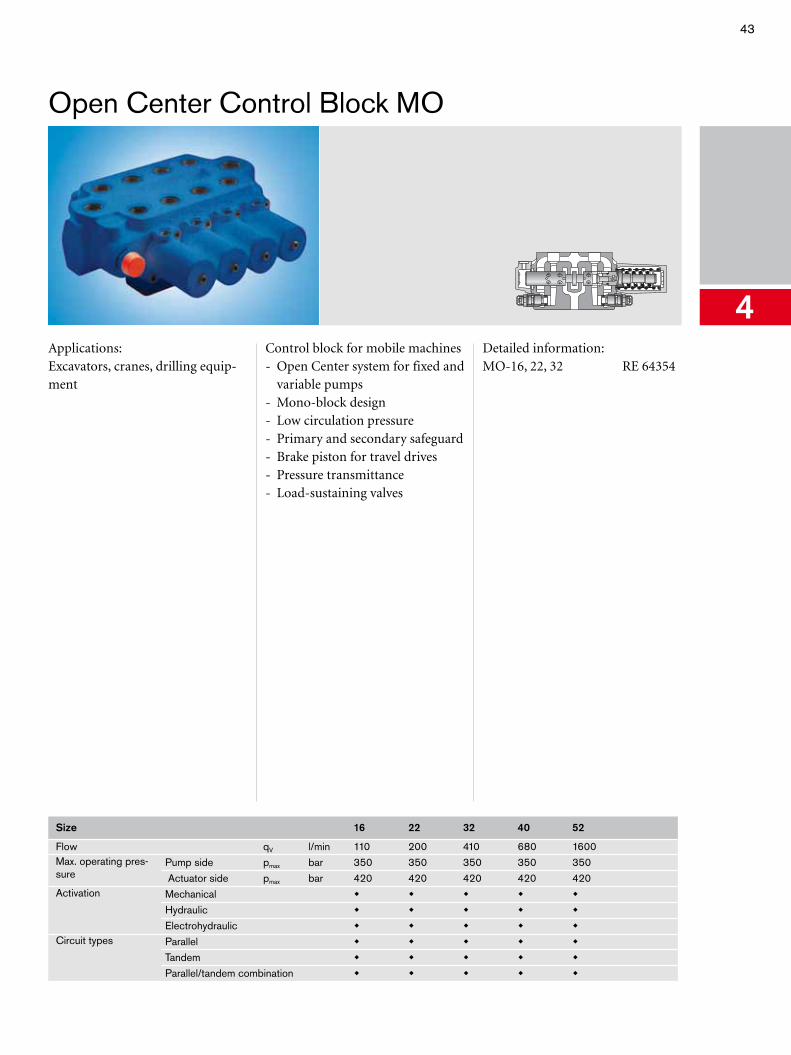
4Applications:Excavators, cranes, drilling equip-ment
Control block for mobile machines- Open Center system for fixed and
variable pumps- Mono-block design- Low circulation pressure- Primary and secondary safeguard- Brake piston for travel drives- Pressure transmittance- Load-sustaining valves
Detailed information:MO-16, 22, 32 RE 64354
Size 16 22 32 40 52
Flow qV l/min 110 200 410 680 1600Max. operating pres-sure
Pump side pmax bar 350 350 350 350 350 Actuator side pmax bar 420 420 420 420 420
Activation Mechanical
Hydraulic
Electrohydraulic Circuit types Parallel
Tandem
Parallel/tandem combination
44 Mobile Controls
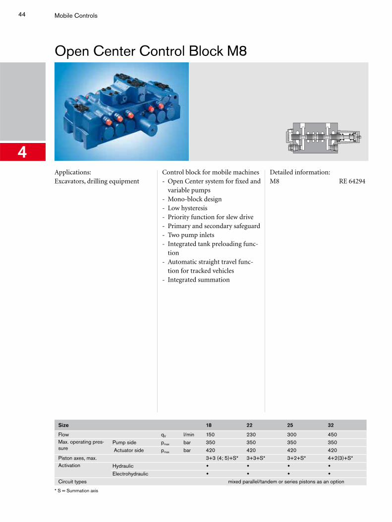
Open Center Control Block M8
4Applications:Excavators, drilling equipment
Control block for mobile machines- Open Center system for fixed and
variable pumps- Mono-block design- Low hysteresis- Priority function for slew drive- Primary and secondary safeguard- Two pump inlets- Integrated tank preloading func-
tion- Automatic straight travel func-
tion for tracked vehicles- Integrated summation
Detailed information:M8 RE 64294
Size 18 22 25 32
Flow qV l/min 150 230 300 450Max. operating pres-sure
Pump side pmax bar 350 350 350 350 Actuator side pmax bar 420 420 420 420
Piston axes, max. 3+3 (4; 5)+S* 3+3+S* 3+2+S* 4+2(3)+S*Activation Hydraulic
Electrohydraulic
Circuit types mixed parallel/tandem or series pistons as an option
* S = Summation axis
45
LUDV Control Block SX
T
P
A B
LS
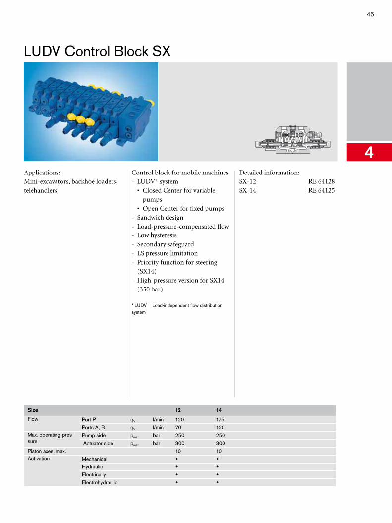
4Applications:Mini-excavators, backhoe loaders, telehandlers
Control block for mobile machines- LUDV* system • Closed Center for variable
pumps • Open Center for fixed pumps- Sandwich design- Load-pressure-compensated flow- Low hysteresis- Secondary safeguard- LS pressure limitation- Priority function for steering
(SX14)- High-pressure version for SX14
(350 bar)
* LUDV = Load-independent flow distribution system
Detailed information:SX-12 RE 64128SX-14 RE 64125
Size 12 14
Flow Port P qV l/min 120 175Ports A, B qV l/min 70 120
Max. operating pres-sure
Pump side pmax bar 250 250 Actuator side pmax bar 300 300
Piston axes, max. 10 10Activation Mechanical
Hydraulic
Electrically
Electrohydraulic
46 Mobile Controls
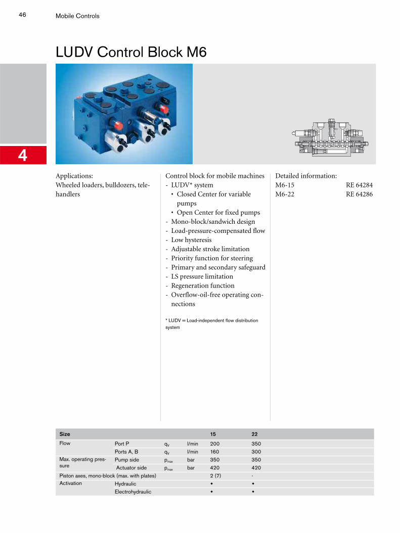
LUDV Control Block M6
4Applications:Wheeled loaders, bulldozers, tele-handlers
Control block for mobile machines- LUDV* system • Closed Center for variable
pumps • Open Center for fixed pumps- Mono-block/sandwich design- Load-pressure-compensated flow- Low hysteresis- Adjustable stroke limitation- Priority function for steering- Primary and secondary safeguard- LS pressure limitation- Regeneration function- Overflow-oil-free operating con-
nections
* LUDV = Load-independent flow distribution system
Detailed information:M6-15 RE 64284M6-22 RE 64286
Size 15 22
Flow Port P qV l/min 200 350Ports A, B qV l/min 160 300
Max. operating pres-sure
Pump side pmax bar 350 350 Actuator side pmax bar 420 420
Piston axes, mono-block (max. with plates) 2 (7) -Activation Hydraulic
Electrohydraulic
47
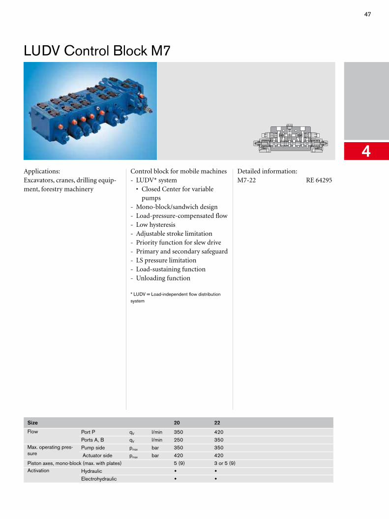
LUDV Control Block M7
4Applications:Excavators, cranes, drilling equip-ment, forestry machinery
Control block for mobile machines- LUDV* system • Closed Center for variable
pumps- Mono-block/sandwich design- Load-pressure-compensated flow- Low hysteresis- Adjustable stroke limitation- Priority function for slew drive- Primary and secondary safeguard- LS pressure limitation- Load-sustaining function- Unloading function
* LUDV = Load-independent flow distribution system
Detailed information:M7-22 RE 64295
Size 20 22
Flow Port P qV l/min 350 420Ports A, B qV l/min 250 350
Max. operating pres-sure
Pump side pmax bar 350 350 Actuator side pmax bar 420 420
Piston axes, mono-block (max. with plates) 5 (9) 3 or 5 (9)Activation Hydraulic
Electrohydraulic
48 Mobile Controls
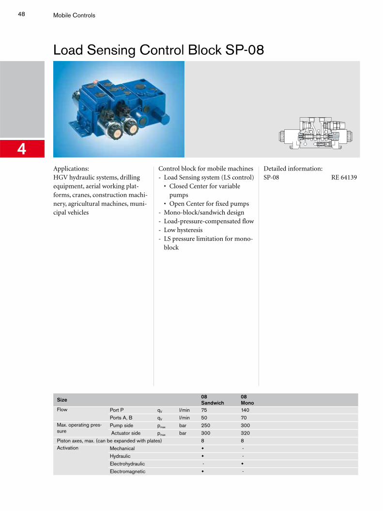
Load Sensing Control Block SP-08
4Applications:HGV hydraulic systems, drilling equipment, aerial working plat-forms, cranes, construction machi-nery, agricultural machines, muni-cipal vehicles
Control block for mobile machines- Load Sensing system (LS control) • Closed Center for variable
pumps • Open Center for fixed pumps- Mono-block/sandwich design- Load-pressure-compensated flow- Low hysteresis- LS pressure limitation for mono-
block
Detailed information:SP-08 RE 64139
Size 08Sandwich
08Mono
Flow Port P qV l/min 75 140Ports A, B qV l/min 50 70
Max. operating pres-sure
Pump side pmax bar 250 300 Actuator side pmax bar 300 320
Piston axes, max. (can be expanded with plates) 8 8Activation Mechanical -
Hydraulic -Electrohydraulic -
Electromagnetic -
49
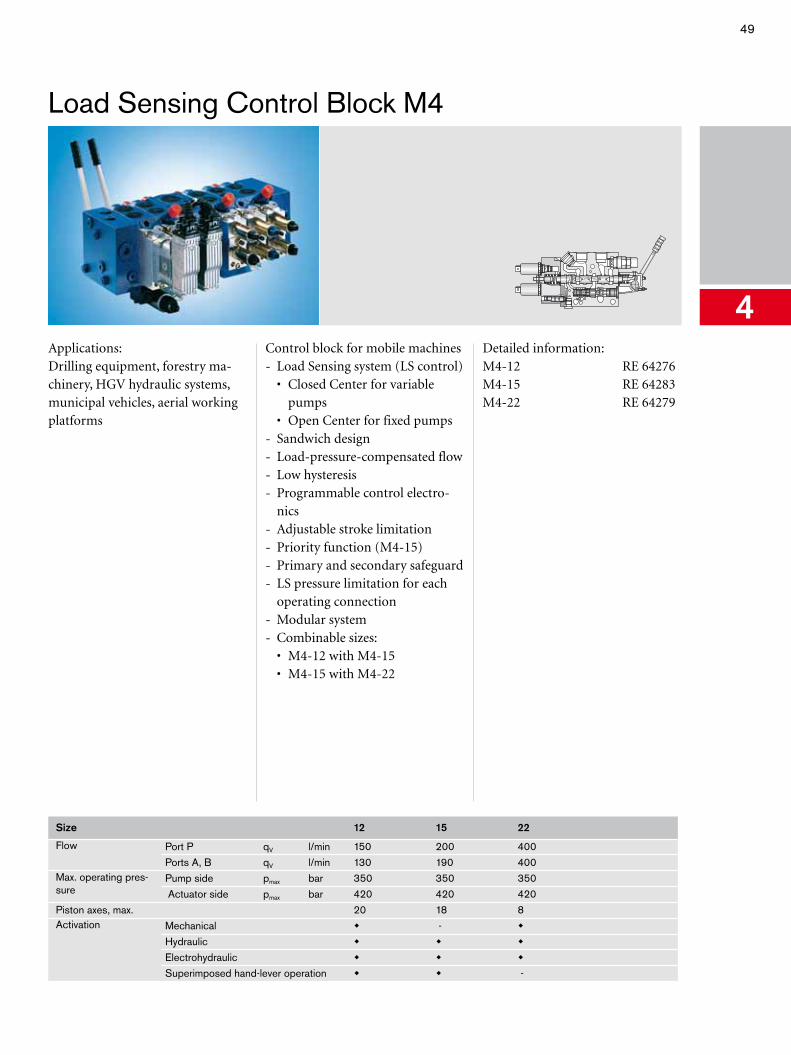
Load Sensing Control Block M4
4Applications:Drilling equipment, forestry ma-chinery, HGV hydraulic systems, municipal vehicles, aerial working platforms
Control block for mobile machines- Load Sensing system (LS control) • Closed Center for variable
pumps • Open Center for fixed pumps- Sandwich design- Load-pressure-compensated flow- Low hysteresis- Programmable control electro-
nics- Adjustable stroke limitation- Priority function (M4-15)- Primary and secondary safeguard- LS pressure limitation for each
operating connection- Modular system- Combinable sizes: • M4-12 with M4-15 • M4-15 with M4-22
Detailed information:M4-12 RE 64276M4-15 RE 64283M4-22 RE 64279
Size 12 15 22
Flow Port P qV l/min 150 200 400Ports A, B qV l/min 130 190 400
Max. operating pres-sure
Pump side pmax bar 350 350 350 Actuator side pmax bar 420 420 420
Piston axes, max. 20 18 8Activation Mechanical -
Hydraulic
Electrohydraulic
Superimposed hand-lever operation -
50 Mobile Controls
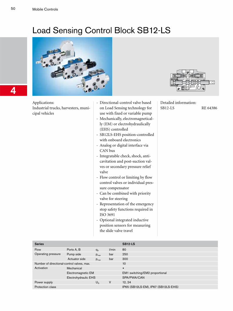
Load Sensing Control Block SB12-LS
4Applications:Industrial trucks, harvesters, muni-cipal vehicles
- Directional-control valve based on Load Sensing technology for use with fixed or variable pump
- Mechanically, electromagnetical-ly (EM) or electrohydraulically (EHS) controlled
- SB12LS-EHS position-controlled with onboard electronics
- Analog or digital interface via CAN bus
- Integratable check, shock, anti-cavitation and post-suction val-ves or secondary pressure relief valve
- Flow control or limiting by flow control valves or individual pres-sure compensator
- Can be combined with priority valve for steering
- Representation of the emergency stop safety functions required in ISO 3691
- Optional integrated inductive position sensors for measuring the slide valve travel
Detailed information:SB12-LS RE 64386
Series SB12-LS
Flow Ports A, B qV l/min 80Operating pressure Pump side pmax bar 250
Actuator side pmax bar 300Number of directional-control valves, max. 10Activation Mechanical
Electromagnetic EM EM1 switching/EM2 proportionalElectrohydraulic EHS SPA/PWA/CAN
Power supply US V 12, 24Protection class IP65 (SB12LS-EM), IP67 (SB12LS-EHS)
51
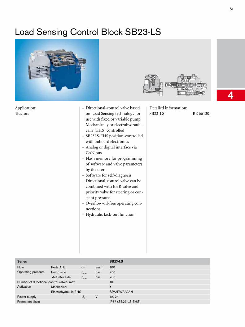
Load Sensing Control Block SB23-LS
4Application:Tractors
- Directional-control valve based on Load Sensing technology for use with fixed or variable pump
- Mechanically or electrohydrauli-cally (EHS) controlled
- SB23LS-EHS position-controlled with onboard electronics
- Analog or digital interface via CAN bus
- Flash memory for programming of software and valve parameters by the user
- Software for self-diagnosis- Directional-control valve can be
combined with EHR valve and priority valve for steering or con-stant pressure
- Overflow-oil-free operating con-nections
- Hydraulic kick-out function
Detailed information:SB23-LS RE 66130
Series SB23-LS
Flow Ports A, B qV l/min 100Operating pressure Pump side pmax bar 250
Actuator side pmax bar 280Number of directional-control valves, max. 10Activation Mechanical
Electrohydraulic EHS SPA/PWA/CANPower supply US V 12, 24Protection class IP67 (SB23-LS-EHS)
52 Mobile Controls
Control Valves EHR
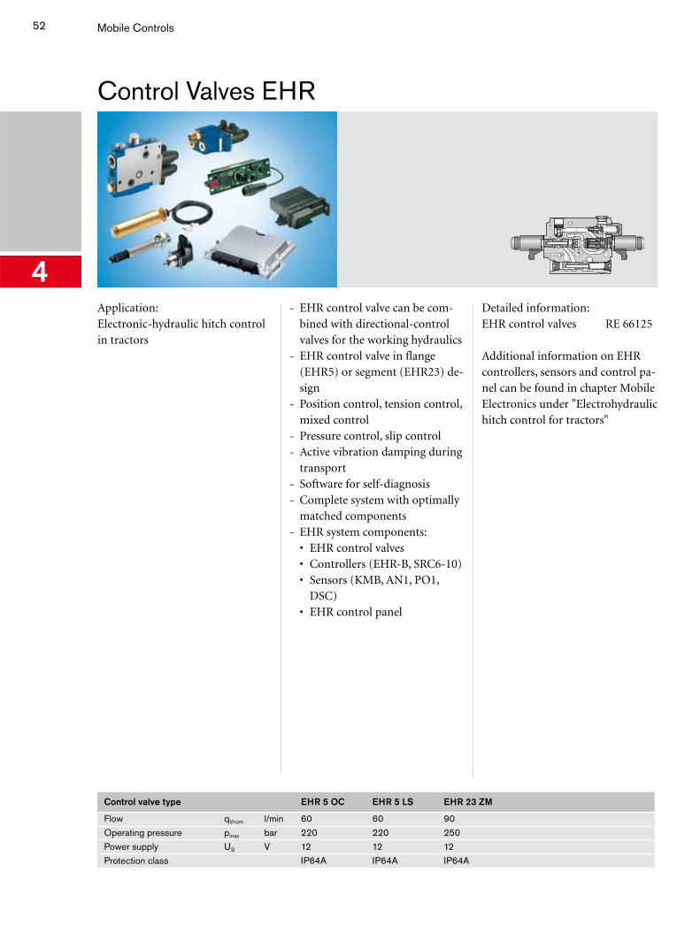
4Application:Electronic-hydraulic hitch control in tractors
- EHR control valve can be com-bined with directional-control valves for the working hydraulics
- EHR control valve in flange (EHR5) or segment (EHR23) de-sign
- Position control, tension control, mixed control
- Pressure control, slip control- Active vibration damping during
transport- Software for self-diagnosis- Complete system with optimally
matched components- EHR system components: • EHR control valves • Controllers (EHR-B, SRC6-10) • Sensors (KMB, AN1, PO1,
DSC) • EHR control panel
Detailed information:EHR control valves RE 66125
Additional information on EHR controllers, sensors and control pa-nel can be found in chapter Mobile Electronics under "Electrohydraulic hitch control for tractors"
Control valve type EHR 5 OC EHR 5 LS EHR 23 ZM
Flow qVnom l/min 60 60 90Operating pressure pmax bar 220 220 250Power supply US V 12 12 12Protection class IP64A IP64A IP64A
53
Central Hydraulics for Tractors CHP
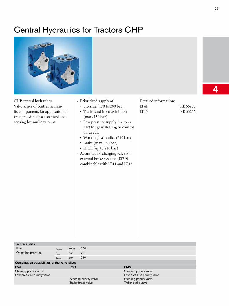
4CHP central hydraulicsValve series of central hydrau-lic components for application in tractors with closed-center/load-sensing hydraulic systems
- Prioritized supply of • Steering (170 to 200 bar) • Trailer and front axle brake
(max. 150 bar) • Low pressure supply (17 to 22
bar) for gear shifting or control oil circuit
• Working hydraulics (210 bar) • Brake (max. 150 bar) • Hitch (up to 210 bar)- Accumulator charging valve for
external brake systems (LT59) combinable with LT41 and LT42
Detailed information:LT41 RE 66233LT43 RE 66235
Technical dataFlow qVnom l/min 200Operating pressure pmax bar 210
pPeak bar 250
Combination possibilities of the valve slicesLT41 LT42 LT43Steering priority valve Low-pressure priority valve
Steering priority valve Low-pressure priority valve
Steering priority valve Trailer brake valve
Steering priority valve Trailer brake valve
54 Mobile Controls
Flow Divider MH2FA/RTM
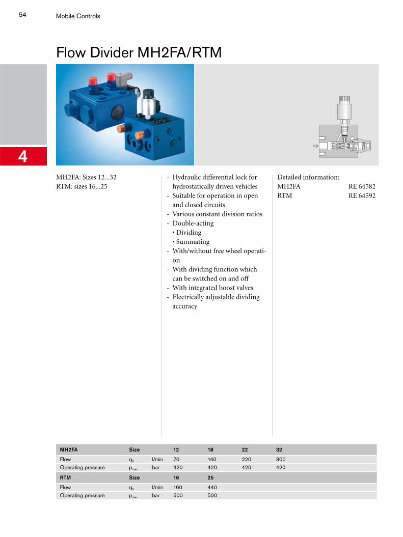
4MH2FA: Sizes 12...32RTM: sizes 16...25
- Hydraulic differential lock for hydrostatically driven vehicles
- Suitable for operation in open and closed circuits
- Various constant division ratios- Double-acting
• Dividing• Summating
- With/without free wheel operati-on
- With dividing function which can be switched on and off
- With integrated boost valves- Electrically adjustable dividing
accuracy
Detailed information:MH2FA RE 64582RTM RE 64592
MH2FA Size 12 18 22 32
Flow qV l/min 70 140 220 300Operating pressure pmax bar 420 420 420 420
RTM Size 16 25
Flow qV l/min 160 440Operating pressure pmax bar 500 500
55
Pipe Burst Safety Valves MHRBCheck-Q-Meter FD
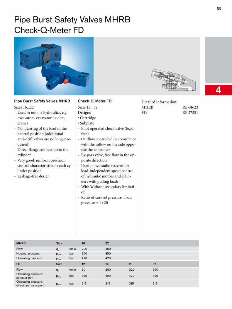
4Pipe Burst Safety Valves MHRB
Sizes 16...22- Used in mobile hydraulics, e.g.
excavators, excavator loaders, cranes
- No lowering of the load in the neutral position (additional anti-drift valves are no longer re-quired)
- Direct flange connection to the cylinder
- Very good, uniform precision control characteristics in each cy-linder position
- Leakage-free design
Check-Q-Meter FD
Sizes 12...32Designs• Cartridge• Subplate- Pilot operated check valve (leak-
free)- Outflow controlled in accordance
with the inflow on the side oppo-site the consumer
- By-pass valve, free flow in the op-posite direction
- Used in hydraulic systems for load-independent speed control of hydraulic motors and cylin-ders with pulling loads
- With/without secondary limitati-on
- Ratio of control pressure : load pressure = 1 : 20
Detailed information:MHRB RE 64623FD RE 27551
MHRB Size 16 22
Flow qV l/min 200 400Nominal pressure pnom bar 350 350Operating pressure pmax bar 420 420
FD Size 12 16 25 32
Flow qV l/min 80 200 320 560Operating pressure: actuator port
pmax bar 420 420 420 420
Operating pressure: directional valve port
pmax bar 315 315 315 315
56 Mobile Controls
Stabilizing Module RSM2Pilot Oil Supply System MHSTE
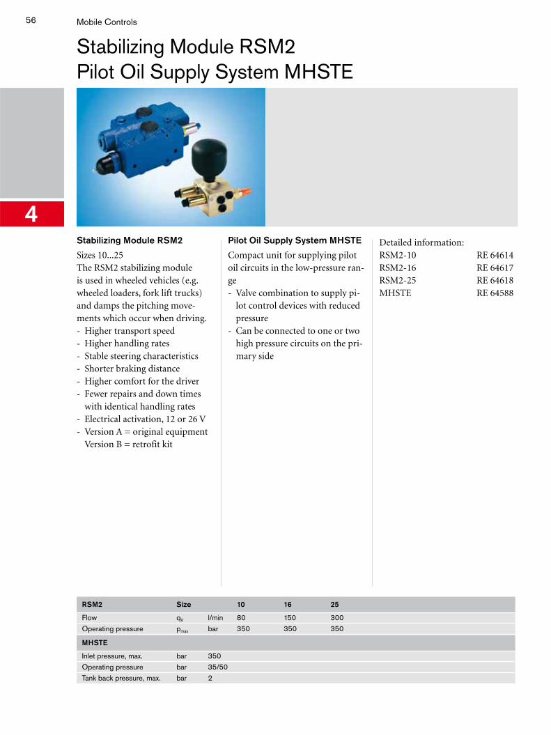
4Stabilizing Module RSM2
Sizes 10...25The RSM2 stabilizing module is used in wheeled vehicles (e.g. wheeled loaders, fork lift trucks) and damps the pitching move-ments which occur when driving.- Higher transport speed- Higher handling rates- Stable steering characteristics- Shorter braking distance- Higher comfort for the driver- Fewer repairs and down times
with identical handling rates- Electrical activation, 12 or 26 V- Version A = original equipment
Version B = retrofit kit
Pilot Oil Supply System MHSTE
Compact unit for supplying pilot oil circuits in the low-pressure ran-ge- Valve combination to supply pi-
lot control devices with reduced pressure
- Can be connected to one or two high pressure circuits on the pri-mary side
Detailed information:RSM2-10 RE 64614RSM2-16 RE 64617RSM2-25 RE 64618MHSTE RE 64588
RSM2 Size 10 16 25
Flow qV l/min 80 150 300Operating pressure pmax bar 350 350 350
MHSTE
Inlet pressure, max. bar 350Operating pressure bar 35/50Tank back pressure, max. bar 2
57
Pressure, Flow, Check Valves
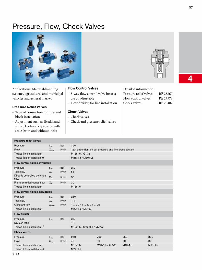
4Applications: Material-handling systems, agricultural and municipal vehicles and general market
Pressure Relief Valves
- Type of connection for pipe and block installation
- Adjustment such as fixed, hand wheel, lead-seal capable or with scale (with and without lock)
Flow Control Valves
- 3-way flow control valve invaria-ble or adjustable
- Flow divider, for line installation
Check Valves
- Check valves- Check and pressure relief valves
Detailed information:Pressure relief valves RE 25860Flow control valves RE 27574Check valves RE 20402
Pressure relief valves
Pressure pmax bar 350Flow Qmax l/min 120, dependent on set pressure and line cross sectionThread (line installation) M18x1,5 / G 1/2Thread (block installation) M26x1.5 / M30x1,5
Flow control valves, invariable
Pressure pmax bar 210Total flow QP l/min 55Directly controlled constant flow
QA l/min 30
Pilot-controlled const. flow QA l/min 30Thread (line installation) M18x1,5
Flow control valves, adjustable
Pressure pmax bar 250Total flow QP l/min 114Constant flow QREG l/min 1 ... 30 / 1 ... 47 / 1 ... 75Thread (line installation) M22x1,5 / M27x2
Flow divider
Pressure pmax bar 310Division ratio 1:1Thread (line installation) 1) M18x1,5 / M22x1,5 / M27x2
Check valves
Pressure pmax bar 250 200 250 300Flow Qmax l/min 45 50 60 80Thread (line installation) M18x1,5 M18x1,5 / G 1/2 M18x1,5 M18x1,5Thread (block installation) M22x1,5 - - -
¹) Port P
58 Mobile Controls
Hydraulic Remotely Powered Brake LT
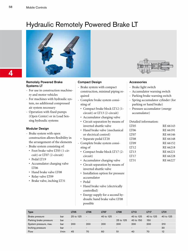
4Remotely Powered Brake Systems LT- For use in construction machine-
ry and motor vehicles- For machines with hydraulic sys-
tem, no additional compressed air system necessary
- Operation with fixed pumps (Open Center) or in Load Sen-sing hydraulic systems
Modular Design
- Brake system with open construction allows flexibility in the arrangement of the elements
- Brake system consisting of: • Foot brake valve LT05 (1-cir-
cuit) or LT07 (2-circuit) • Pedal LT19 • Accumulator charging valve
LT06 • Hand brake valve LT08 • Relay valve LT09 • Brake valve, inching LT31
Compact Design
- Brake system with compact construction, minimal piping re-quired
- Complete brake system consi-sting of
• Compact brake block LT12 (1-circuit) or LT13 (2-circuit)
• Accumulator charging valve • Circuit separation by means of
inverted shuttle valve • Hand brake valve (mechanical
or electrical control) • Separate pedal LT20- Complete brake system consi-
sting of • Compact brake block LT17 (2-
circuit) • Accumulator charging valve • Circuit separation by means of
inverted shuttle valve • Installation option for pressure
accumulator • Pedal • Hand brake valve (electrically
controlled) • Energy supply for a second hy-
draulic hand brake valve LT08 possible
Accessories
- Brake light switch- Accumulator warning switch- Parking brake warning switch- Spring accumulator cylinder (for
parking or hand brake)- Pressure accumulator (energy
accumulator)
Detailed information:LT05 RE 66143LT06 RE 66191LT07 RE 66146LT08 RE 66148LT09 RE 66152LT12 RE 66218LT13 RE 66221LT17 RE 66228LT31 RE 66227
Type LT05 LT06 LT07 LT08 LT13 LT17 LT31
Brake pressure bar 25 to 125 - 40 to 125 - 40 to 125 40 to 125 40 to 125Parking brake pressure bar - - - 25 to 125 40 to 150 150 -System pressure, max. bar 200 200 200 200 200 200 210Inching pressure bar - - - - - - 30Flow l/min 45 70 60 51 40 70 12
59
Trailer Brake Valve BV1
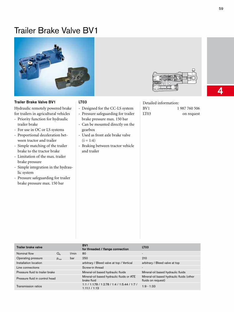
4Trailer Brake Valve BV1
Hydraulic remotely powered brake for trailers in agricultural vehicles- Priority function for hydraulic
trailer brake- For use in OC or LS systems- Proportional deceleration bet-
ween tractor and trailer- Simple matching of the trailer
brake to the tractor brake- Limitation of the max. trailer
brake pressure- Simple integration in the hydrau-
lic system- Pressure safeguarding for trailer
brake pressure max. 150 bar
LT03
- Designed for the CC-LS system- Pressure safeguarding for trailer
brake pressure max. 150 bar- Can be mounted directly on the
gearbox- Used as front axle brake valve
(i = 1:4)- Braking between tractor vehicle
and trailer
Detailed information:BV1 1 987 760 506LT03 on request
Trailer brake valve BV1 for threaded / flange connection LT03
Nominal flow QN l/min 80 -Operating pressure pmax bar 250 210Installation location arbitrary / Bleed valve at top / Vertical arbitrary / Bleed valve at topLine connections Screw-in thread -Pressure fluid to trailer brake Mineral-oil based hydraulic fluids Mineral-oil based hydraulic fluids
Pressure fluid in control headMineral-oil based hydraulic fluids or ATE brake fluid
Mineral-oil based hydraulic fluids (other fluids on request)
Transmission ratios1:1 / 1:1.78 / 1:2.78 / 1:4 / 1:5.44 / 1:7 / 1:11.1 / 1:13
1:9 - 1:33
60 Mobile Controls
Hydrostatic Steering Units LAG
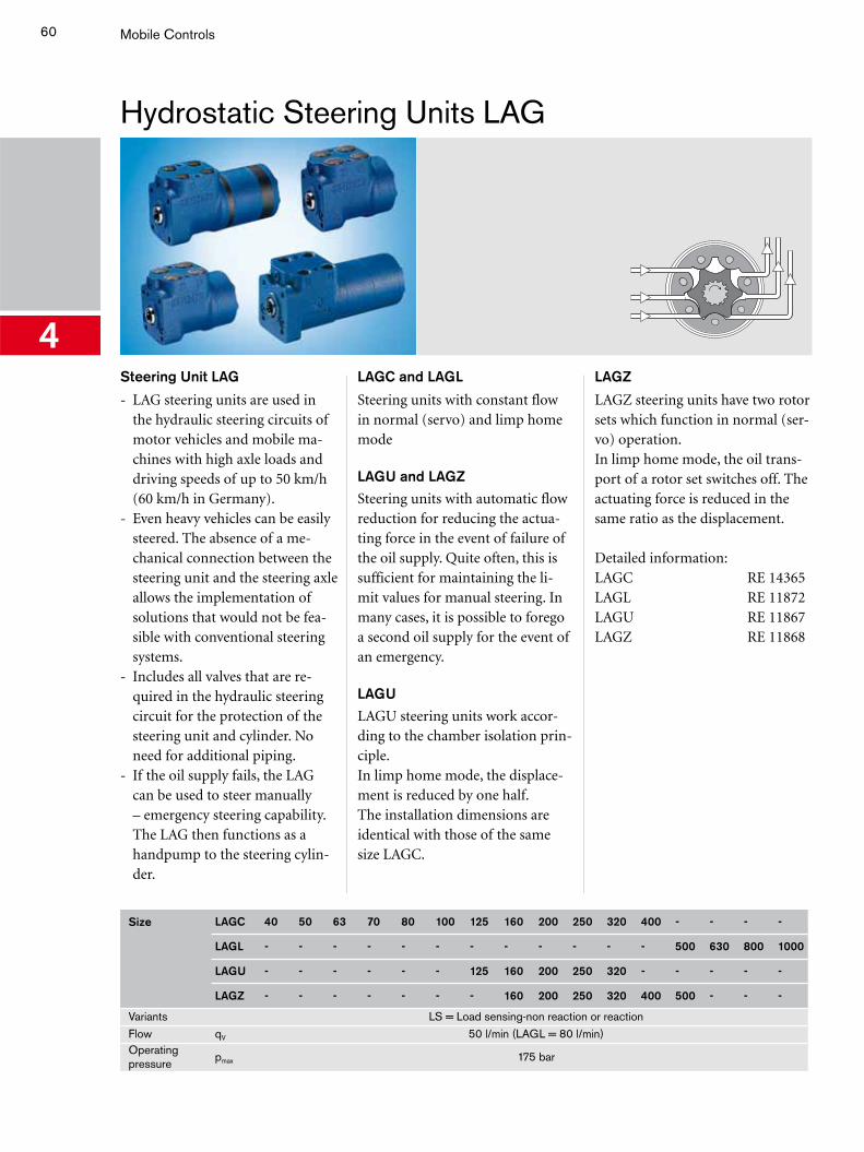
4Steering Unit LAG
- LAG steering units are used in the hydraulic steering circuits of motor vehicles and mobile ma-chines with high axle loads and driving speeds of up to 50 km/h (60 km/h in Germany).
- Even heavy vehicles can be easily steered. The absence of a me-chanical connection between the steering unit and the steering axle allows the implementation of solutions that would not be fea-sible with conventional steering systems.
- Includes all valves that are re-quired in the hydraulic steering circuit for the protection of the steering unit and cylinder. No need for additional piping.
- If the oil supply fails, the LAG can be used to steer manually – emergency steering capability. The LAG then functions as a handpump to the steering cylin-der.
LAGC and LAGL
Steering units with constant flow in normal (servo) and limp home mode
LAGU and LAGZ
Steering units with automatic flow reduction for reducing the actua-ting force in the event of failure of the oil supply. Quite often, this is sufficient for maintaining the li-mit values for manual steering. In many cases, it is possible to forego a second oil supply for the event of an emergency.
LAGU
LAGU steering units work accor-ding to the chamber isolation prin-ciple.In limp home mode, the displace-ment is reduced by one half.The installation dimensions are identical with those of the same size LAGC.
LAGZ
LAGZ steering units have two rotor sets which function in normal (ser-vo) operation.In limp home mode, the oil trans-port of a rotor set switches off. The actuating force is reduced in the same ratio as the displacement.
Detailed information:LAGC RE 14365LAGL RE 11872LAGU RE 11867LAGZ RE 11868
Size LAGC 40 50 63 70 80 100 125 160 200 250 320 400 - - - -
LAGL - - - - - - - - - - - - 500 630 800 1000
LAGU - - - - - - 125 160 200 250 320 - - - - -
LAGZ - - - - - - - 160 200 250 320 400 500 - - -
Variants LS = Load sensing-non reaction or reactionFlow qV 50 l/min (LAGL = 80 l/min)Operating pressure
pmax 175 bar
61
Priority Valve LPSLAB Steering Columns and Sensor
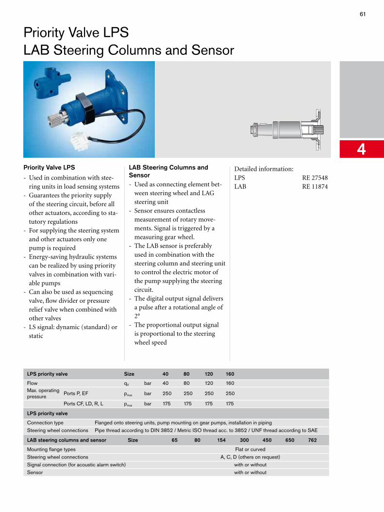
4Priority Valve LPS
- Used in combination with stee-ring units in load sensing systems
- Guarantees the priority supply of the steering circuit, before all other actuators, according to sta-tutory regulations
- For supplying the steering system and other actuators only one pump is required
- Energy-saving hydraulic systems can be realized by using priority valves in combination with vari-able pumps
- Can also be used as sequencing valve, flow divider or pressure relief valve when combined with other valves
- LS signal: dynamic (standard) or static
LAB Steering Columns and Sensor - Used as connecting element bet-
ween steering wheel and LAG steering unit
- Sensor ensures contactless measurement of rotary move-ments. Signal is triggered by a measuring gear wheel.
- The LAB sensor is preferably used in combination with the steering column and steering unit to control the electric motor of the pump supplying the steering circuit.
- The digital output signal delivers a pulse after a rotational angle of 2°
- The proportional output signal is proportional to the steering wheel speed
Detailed information:LPS RE 27548LAB RE 11874
LPS priority valve Size 40 80 120 160
Flow qV bar 40 80 120 160Max. operating pressure
Ports P, EF pmax bar 250 250 250 250
Ports CF, LD, R, L pmax bar 175 175 175 175
LPS priority valve
Connection type Flanged onto steering units, pump mounting on gear pumps, installation in pipingSteering wheel connections Pipe thread according to DIN 3852 / Metric ISO thread acc. to 3852 / UNF thread according to SAE
LAB steering columns and sensor Size 65 80 154 300 450 650 762
Mounting flange types Flat or curvedSteering wheel connections A, C, D (others on request)Signal connection (for acoustic alarm switch) with or withoutSensor with or without
62 Mobile Controls
Hydraulic and Electronic Pilot Control Devices TH
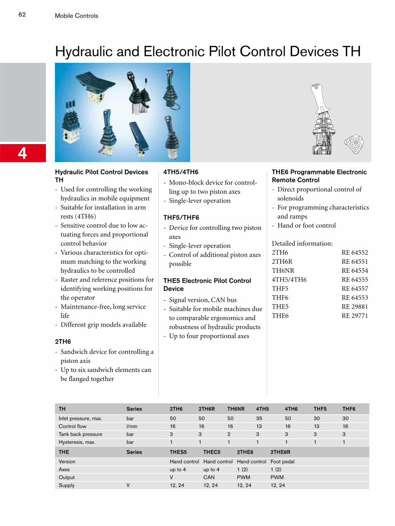
4Hydraulic Pilot Control Devices TH- Used for controlling the working
hydraulics in mobile equipment- Suitable for installation in arm
rests (4TH6)- Sensitive control due to low ac-
tuating forces and proportional control behavior
- Various characteristics for opti-mum matching to the working hydraulics to be controlled
- Raster and reference positions for identifying working positions for the operator
- Maintenance-free, long service life
- Different grip models available
2TH6
- Sandwich device for controlling a piston axis
- Up to six sandwich elements can be flanged together
4TH5/4TH6
- Mono-block device for control-ling up to two piston axes
- Single-lever operation
THF5/THF6
- Device for controlling two piston axes
- Single-lever operation- Control of additional piston axes
possible
THE5 Electronic Pilot Control Device
- Signal version, CAN bus- Suitable for mobile machines due
to comparable ergonomics and robustness of hydraulic products
- Up to four proportional axes
THE6 Programmable Electronic Remote Control - Direct proportional control of
solenoids- For programming characteristics
and ramps- Hand or foot control
Detailed information:2TH6 RE 645522TH6R RE 64551TH6NR RE 645544TH5/4TH6 RE 64555THF5 RE 64557THF6 RE 64553THE5 RE 29881THE6 RE 29771
TH Series 2TH6 2TH6R TH6NR 4TH5 4TH6 THF5 THF6
Inlet pressure, max. bar 50 50 50 35 50 30 30Control flow l/min 16 16 16 13 16 13 16Tank back pressure bar 3 3 2 3 3 3 3Hysteresis, max. bar 1 1 1 1 1 1 1
THE Series THES5 THEC5 2THE6 2THE6R
Version Hand control Hand control Hand control Foot pedalAxes up to 4 up to 4 1 (2) 1 (2)Output V CAN PWM PWMSupply V 12, 24 12, 24 12, 24 12, 24
63
5
Compact Hydraulics
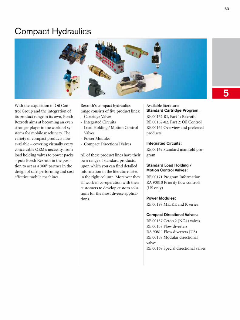
With the acquisition of Oil Con-trol Group and the integration of its product range in its own, Bosch Rexroth aims at becoming an even stronger player in the world of sy-stems for mobile machinery. The variety of compact products now available – covering virtually every conceivable OEM’s necessity, from load holding valves to power packs – puts Bosch Rexroth in the posi-tion to act as a 360° partner in the design of safe, performing and cost effective mobile machines.
Rexroth‘s compact hydraulicsrange consists of five product lines:- Cartridge Valves- Integrated Circuits- Load Holding / Motion Control
Valves- Power Modules- Compact Directional Valves
All of these product lines have their own range of standard products, upon which you can find detailed information in the literature listed in the right column. Moreover they all work in co-operation with their customers to develop custom solu-tions for the most diverse applica-tions.
Available literature:Standard Cartridge Program:
RE 00162-01, Part 1: RexrothRE 00162-02, Part 2: Oil ControlRE 00164 Overview and preferred products
Integrated Circuits:
RE 00169 Standard manifold pro-gram
Standard Load Holding / Motion Control Valves:
RE 00171 Program InformationRA 90810 Priority flow controls (US only)
Power Modules:
RE 00198 ME, KE and K series
Compact Directional Valves:
RE 00157 Cetop 2 (NG4) valvesRE 00158 Flow divertersRA 90811 Flow diverters (US)RE 00159 Modular directional valvesRE 00169 Special directional valves
64
5
Compact Hydraulics
Cartridge Valves: Counterbalance Valves
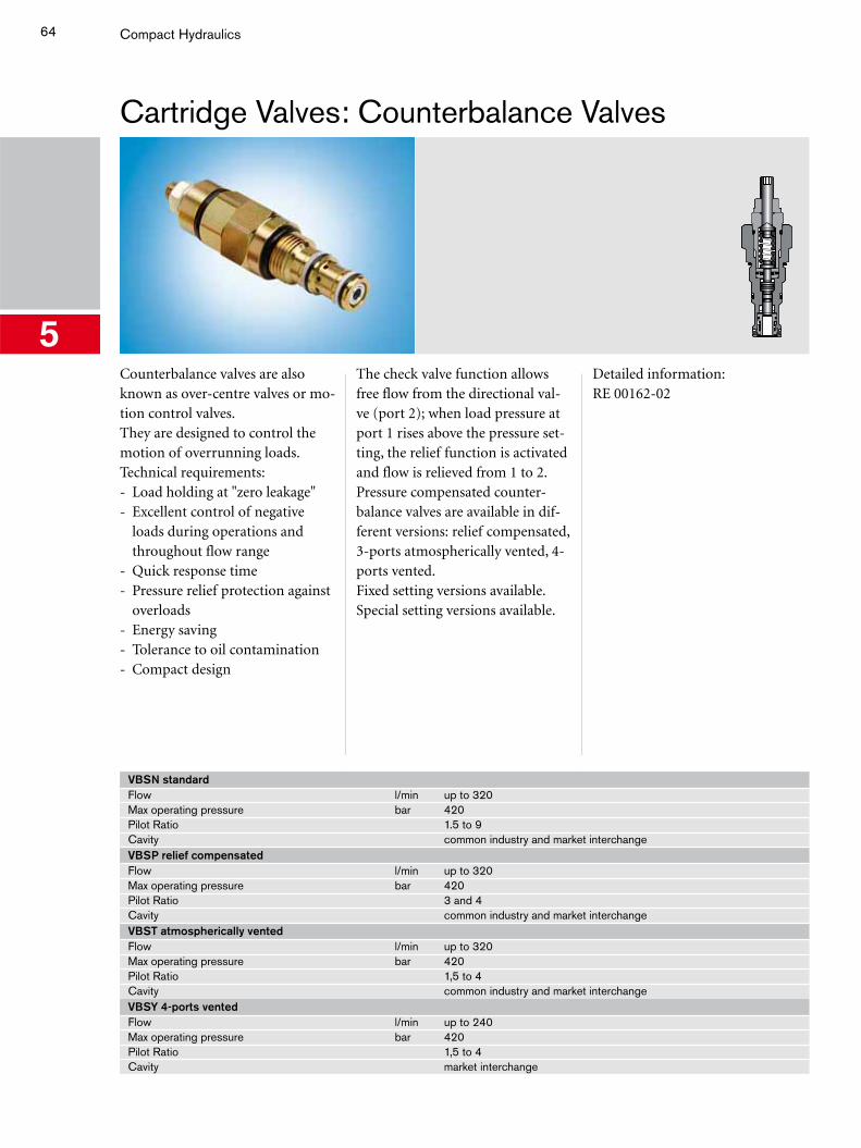
Counterbalance valves are also known as over-centre valves or mo-tion control valves.They are designed to control the motion of overrunning loads.Technical requirements:- Load holding at "zero leakage"- Excellent control of negative
loads during operations and throughout flow range
- Quick response time - Pressure relief protection against
overloads- Energy saving- Tolerance to oil contamination- Compact design
The check valve function allows free flow from the directional val-ve (port 2); when load pressure at port 1 rises above the pressure set-ting, the relief function is activated and flow is relieved from 1 to 2.Pressure compensated counter-balance valves are available in dif-ferent versions: relief compensated, 3-ports atmospherically vented, 4-ports vented.Fixed setting versions available.Special setting versions available.
Detailed information:RE 00162-02
VBSN standardFlow l/min up to 320Max operating pressure bar 420Pilot Ratio 1.5 to 9Cavity common industry and market interchangeVBSP relief compensatedFlow l/min up to 320Max operating pressure bar 420Pilot Ratio 3 and 4Cavity common industry and market interchangeVBST atmospherically ventedFlow l/min up to 320Max operating pressure bar 420Pilot Ratio 1,5 to 4Cavity common industry and market interchangeVBSY 4-ports ventedFlow l/min up to 240Max operating pressure bar 420Pilot Ratio 1,5 to 4Cavity market interchange
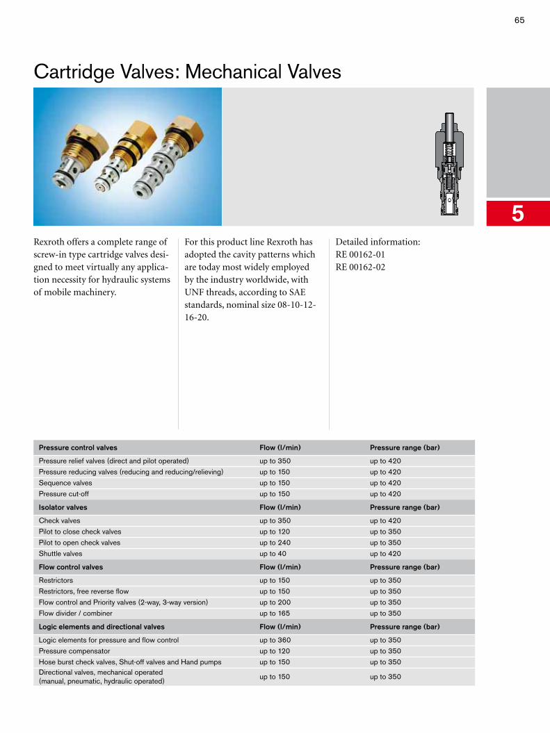
65
5
Cartridge Valves: Mechanical Valves
Rexroth offers a complete range of screw-in type cartridge valves desi-gned to meet virtually any applica-tion necessity for hydraulic systems of mobile machinery.
For this product line Rexroth has adopted the cavity patterns which are today most widely employed by the industry worldwide, with UNF threads, according to SAE standards, nominal size 08-10-12-16-20.
Detailed information:RE 00162-01RE 00162-02
Pressure control valves Flow (l/min) Pressure range (bar)
Pressure relief valves (direct and pilot operated) up to 350 up to 420Pressure reducing valves (reducing and reducing/relieving) up to 150 up to 420Sequence valves up to 150 up to 420Pressure cut-off up to 150 up to 420
Isolator valves Flow (l/min) Pressure range (bar)
Check valves up to 350 up to 420Pilot to close check valves up to 120 up to 350Pilot to open check valves up to 240 up to 350Shuttle valves up to 40 up to 420
Flow control valves Flow (l/min) Pressure range (bar)
Restrictors up to 150 up to 350Restrictors, free reverse flow up to 150 up to 350Flow control and Priority valves (2-way, 3-way version) up to 200 up to 350Flow divider / combiner up to 165 up to 350
Logic elements and directional valves Flow (l/min) Pressure range (bar)
Logic elements for pressure and flow control up to 360 up to 350Pressure compensator up to 120 up to 350Hose burst check valves, Shut-off valves and Hand pumps up to 150 up to 350Directional valves, mechanical operated(manual, pneumatic, hydraulic operated)
up to 150 up to 350
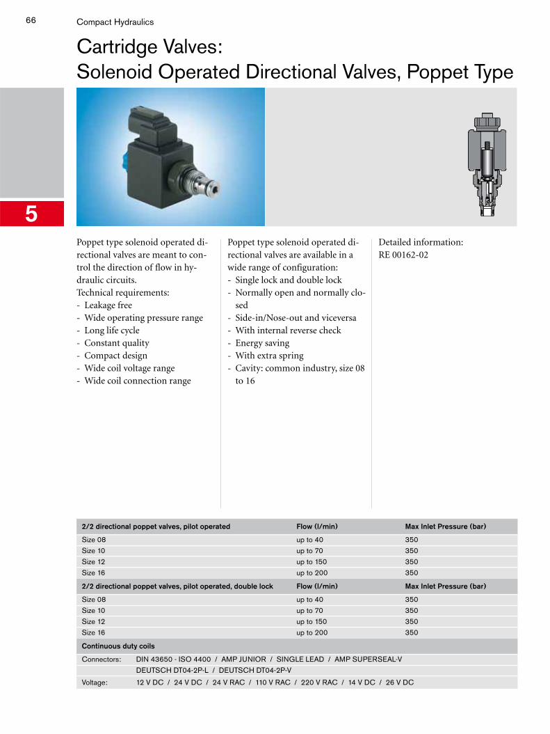
66
5
Compact Hydraulics
Cartridge Valves:Solenoid Operated Directional Valves, Poppet Type
Poppet type solenoid operated di-rectional valves are meant to con-trol the direction of flow in hy-draulic circuits.Technical requirements:- Leakage free- Wide operating pressure range- Long life cycle - Constant quality- Compact design- Wide coil voltage range- Wide coil connection range
Poppet type solenoid operated di-rectional valves are available in a wide range of configuration:- Single lock and double lock- Normally open and normally clo-
sed- Side-in/Nose-out and viceversa- With internal reverse check- Energy saving- With extra spring- Cavity: common industry, size 08
to 16
Detailed information:RE 00162-02
2/2 directional poppet valves, pilot operated Flow (l/min) Max Inlet Pressure (bar)
Size 08 up to 40 350Size 10 up to 70 350Size 12 up to 150 350Size 16 up to 200 350
2/2 directional poppet valves, pilot operated, double lock Flow (l/min) Max Inlet Pressure (bar)
Size 08 up to 40 350Size 10 up to 70 350Size 12 up to 150 350Size 16 up to 200 350
Continuous duty coils
Connectors: DIN 43650 - ISO 4400 / AMP JUNIOR / SINGLE LEAD / AMP SUPERSEAL-VDEUTSCH DT04-2P-L / DEUTSCH DT04-2P-V
Voltage: 12 V DC / 24 V DC / 24 V RAC / 110 V RAC / 220 V RAC / 14 V DC / 26 V DC
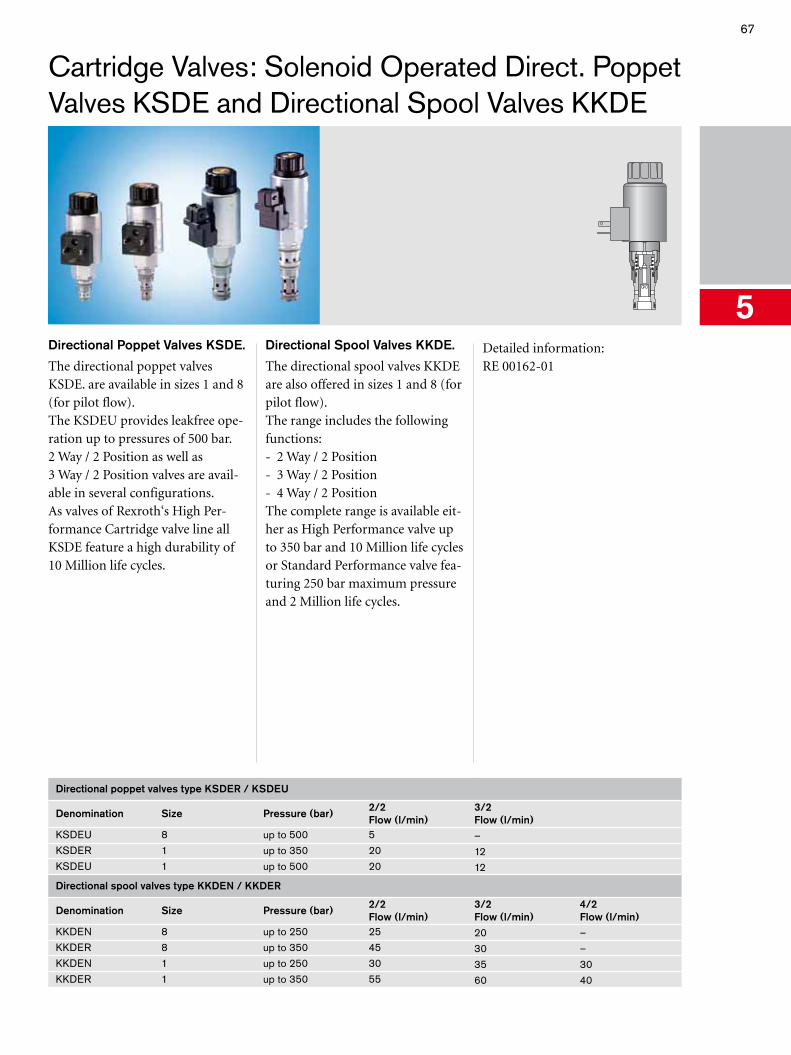
67
5
Cartridge Valves: Solenoid Operated Direct. Poppet Valves KSDE and Directional Spool Valves KKDE
Directional Poppet Valves KSDE.
The directional poppet valves KSDE. are available in sizes 1 and 8 (for pilot flow).The KSDEU provides leakfree ope-ration up to pressures of 500 bar.2 Way / 2 Position as well as 3 Way / 2 Position valves are avail-able in several configurations.As valves of Rexroth‘s High Per-formance Cartridge valve line all KSDE feature a high durability of 10 Million life cycles.
Directional Spool Valves KKDE.
The directional spool valves KKDE are also offered in sizes 1 and 8 (for pilot flow).The range includes the following functions:- 2 Way / 2 Position- 3 Way / 2 Position- 4 Way / 2 PositionThe complete range is available eit-her as High Performance valve up to 350 bar and 10 Million life cycles or Standard Performance valve fea-turing 250 bar maximum pressure and 2 Million life cycles.
Detailed information:RE 00162-01
Directional poppet valves type KSDER / KSDEU
Denomination Size Pressure (bar) 2/2Flow (l/min)
3/2Flow (l/min)
KSDEU 8 up to 500 5 –KSDER 1 up to 350 20 12KSDEU 1 up to 500 20 12
Directional spool valves type KKDEN / KKDER
Denomination Size Pressure (bar) 2/2Flow (l/min)
3/2Flow (l/min)
4/2Flow (l/min)
KKDEN 8 up to 250 25 20 –KKDER 8 up to 350 45 30 –KKDEN 1 up to 250 30 35 30KKDER 1 up to 350 55 60 40
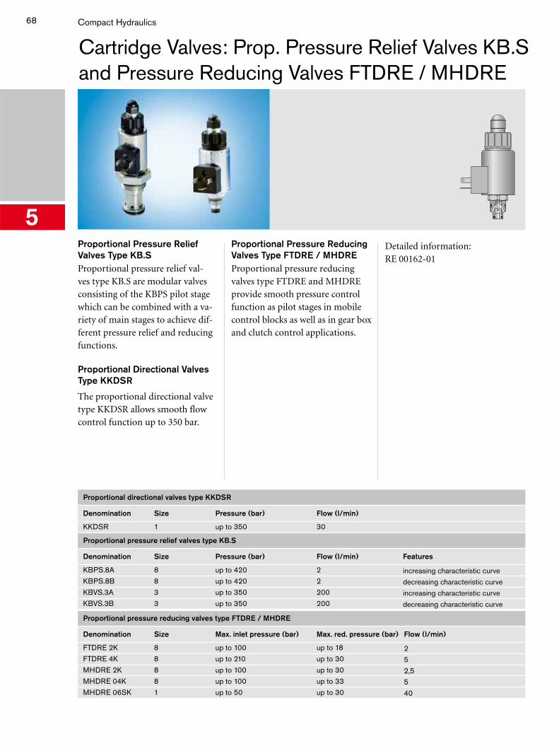
68
5
Compact Hydraulics
Proportional Pressure Relief Valves Type KB.SProportional pressure relief val-ves type KB.S are modular valves consisting of the KBPS pilot stage which can be combined with a va-riety of main stages to achieve dif-ferent pressure relief and reducing functions.
Proportional Directional ValvesType KKDSR
The proportional directional valve type KKDSR allows smooth flow control function up to 350 bar.
Cartridge Valves: Prop. Pressure Relief Valves KB.S and Pressure Reducing Valves FTDRE / MHDRE
Proportional Pressure Reducing Valves Type FTDRE / MHDREProportional pressure reducing valves type FTDRE and MHDRE provide smooth pressure control function as pilot stages in mobile control blocks as well as in gear box and clutch control applications.
Detailed information:RE 00162-01
Proportional directional valves type KKDSR
Denomination Size Pressure (bar) Flow (l/min)
KKDSR 1 up to 350 30
Proportional pressure relief valves type KB.S
Denomination Size Pressure (bar) Flow (l/min) Features
KBPS.8A 8 up to 420 2 increasing characteristic curveKBPS.8B 8 up to 420 2 decreasing characteristic curveKBVS.3A 3 up to 350 200 increasing characteristic curveKBVS.3B 3 up to 350 200 decreasing characteristic curve
Proportional pressure reducing valves type FTDRE / MHDRE
Denomination Size Max. inlet pressure (bar) Max. red. pressure (bar) Flow (l/min)
FTDRE 2K 8 up to 100 up to 18 2FTDRE 4K 8 up to 210 up to 30 5MHDRE 2K 8 up to 100 up to 30 2,5MHDRE 04K 8 up to 100 up to 33 5MHDRE 06SK 1 up to 50 up to 30 40
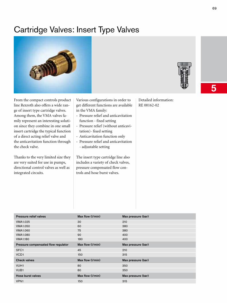
69
5
Cartridge Valves: Insert Type Valves
From the compact controls product line Rexroth also offers a wide ran-ge of insert type cartridge valves. Among them, the VMA valves fa-mily represent an interesting soluti-on since they combine in one small insert cartridge the typical function of a direct acting relief valve and the anticavitation function through the check valve.
Thanks to the very limited size they are very suited for use in pumps, directional control valves as well as integrated circuits.
Various configurations in order to get different functions are available in the VMA family:- Pressure relief and anticavitation
function - fixed setting- Pressure relief (without anticavi-
tation)- fixed setting - Anticavitation function only- Pressure relief and anticavitation
- adjustable setting
The insert type cartridge line also includes a variety of check valves, pressure compensated flow con-trols and hose burst valves.
Detailed information:RE 00162-02
Pressure relief valves Max flow (l/min) Max pressure (bar)
VMA1.025 30 210VMA1.050 60 380VMA1.060 75 380VMA1.080 90 400VMA1.180 180 400
Pressure compensated flow regulator Max flow (l/min) Max pressure (bar)
SFC1 45 210VCD1 150 315
Check valves Max flow (l/min) Max pressure (bar)
VUH1 80 350VUB1 80 350
Hose burst valves Max flow (l/min) Max pressure (bar)
VPN1 150 315
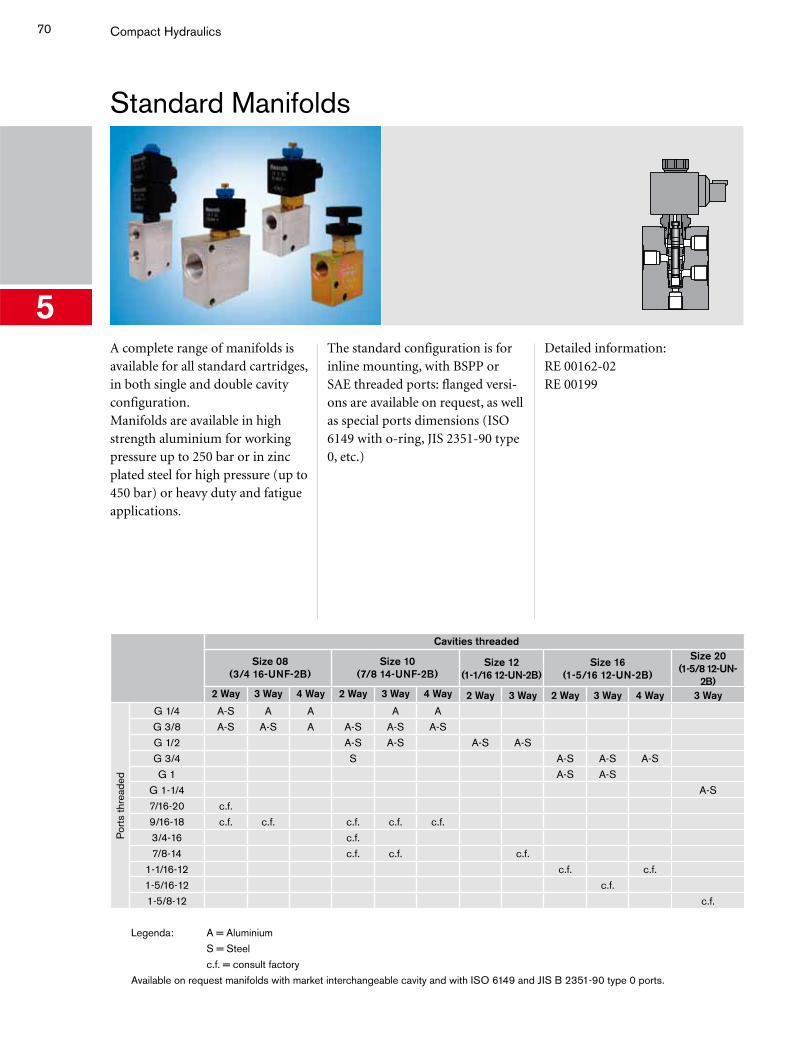
70
5
Compact Hydraulics
Standard Manifolds
A complete range of manifolds is available for all standard cartridges, in both single and double cavity configuration.Manifolds are available in high strength aluminium for working pressure up to 250 bar or in zinc plated steel for high pressure (up to 450 bar) or heavy duty and fatigue applications.
The standard configuration is for inline mounting, with BSPP or SAE threaded ports: flanged versi-ons are available on request, as well as special ports dimensions (ISO 6149 with o-ring, JIS 2351-90 type 0, etc.)
Detailed information:RE 00162-02RE 00199
Cavities threaded
Size 08(3/4 16-UNF-2B)
Size 10(7/8 14-UNF-2B)
Size 12 (1-1/16 12-UN-2B)
Size 16(1-5/16 12-UN-2B)
Size 20(1-5/8 12-UN-
2B)2 Way 3 Way 4 Way 2 Way 3 Way 4 Way 2 Way 3 Way 2 Way 3 Way 4 Way 3 Way
Por
ts th
read
ed
G 1/4 A-S A A A AG 3/8 A-S A-S A A-S A-S A-SG 1/2 A-S A-S A-S A-SG 3/4 S A-S A-S A-SG 1 A-S A-S
G 1-1/4 A-S7/16-20 c.f.9/16-18 c.f. c.f. c.f. c.f. c.f.3/4-16 c.f.7/8-14 c.f. c.f. c.f.
1-1/16-12 c.f. c.f.1-5/16-12 c.f.1-5/8-12 c.f.
Legenda: A = AluminiumS = Steelc.f. = consult factory
Available on request manifolds with market interchangeable cavity and with ISO 6149 and JIS B 2351-90 type 0 ports.
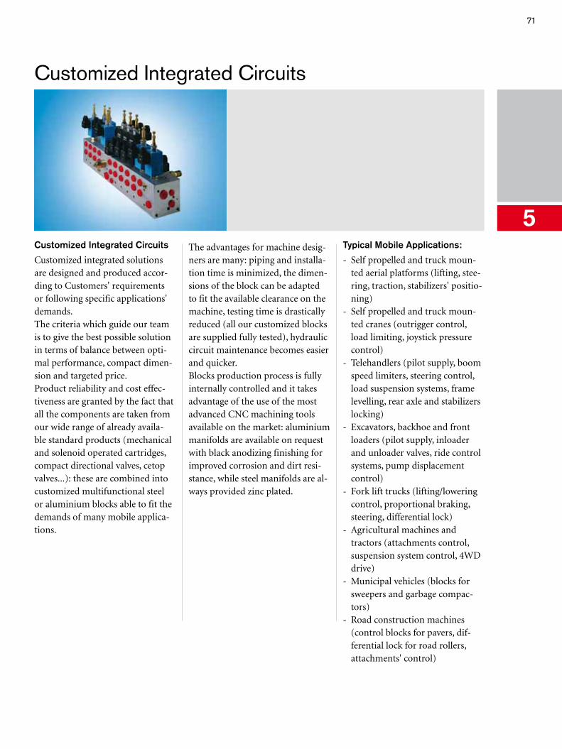
71
5
Customized Integrated Circuits
Customized Integrated Circuits
Customized integrated solutions are designed and produced accor-ding to Customers' requirements or following specific applications' demands.The criteria which guide our team is to give the best possible solution in terms of balance between opti-mal performance, compact dimen-sion and targeted price.Product reliability and cost effec-tiveness are granted by the fact that all the components are taken from our wide range of already availa-ble standard products (mechanical and solenoid operated cartridges, compact directional valves, cetop valves...): these are combined into customized multifunctional steel or aluminium blocks able to fit the demands of many mobile applica-tions.
The advantages for machine desig-ners are many: piping and installa-tion time is minimized, the dimen-sions of the block can be adapted to fit the available clearance on the machine, testing time is drastically reduced (all our customized blocks are supplied fully tested), hydraulic circuit maintenance becomes easier and quicker.Blocks production process is fully internally controlled and it takes advantage of the use of the most advanced CNC machining tools available on the market: aluminium manifolds are available on request with black anodizing finishing for improved corrosion and dirt resi-stance, while steel manifolds are al-ways provided zinc plated.
Typical Mobile Applications:
- Self propelled and truck moun-ted aerial platforms (lifting, stee-ring, traction, stabilizers' positio-ning)
- Self propelled and truck moun-ted cranes (outrigger control, load limiting, joystick pressure control)
- Telehandlers (pilot supply, boom speed limiters, steering control, load suspension systems, frame levelling, rear axle and stabilizers locking)
- Excavators, backhoe and front loaders (pilot supply, inloader and unloader valves, ride control systems, pump displacement control)
- Fork lift trucks (lifting/lowering control, proportional braking, steering, differential lock)
- Agricultural machines and tractors (attachments control, suspension system control, 4WD drive)
- Municipal vehicles (blocks for sweepers and garbage compac-tors)
- Road construction machines (control blocks for pavers, dif-ferential lock for road rollers, attachments' control)
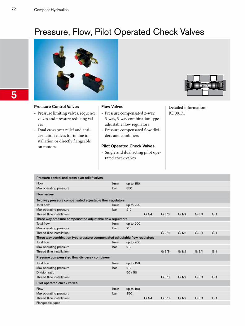
72
5
Compact Hydraulics
Pressure, Flow, Pilot Operated Check Valves
Pressure Control Valves
- Pressure limiting valves, sequence valves and pressure reducing val-ves
- Dual cross over relief and anti-cavitation valves for in line in-stallation or directly flangeable on motors
Flow Valves
- Pressure compensated 2-way, 3-way, 3-way combination type adjustable flow regulators
- Pressure compensated flow divi-ders and combiners
Pilot Operated Check Valves
- Single and dual acting pilot ope-rated check valves
Detailed information:RE 00171
Pressure control and cross over relief valves
Flow l/min up to 150Max operating pressure bar 350
Flow valves
Two way pressure compensated adjustable flow regulatorsTotal flow l/min up to 200Max operating pressure bar 210Thread (line installation) G 1/4 G 3/8 G 1/2 G 3/4 G 1Three way pressure compensated adjustable flow regulatorsTotal flow l/min up to 200Max operating pressure bar 210Thread (line installation) G 3/8 G 1/2 G 3/4 G 1Three way combination type pressure compensated adjustable flow regulatorsTotal flow l/min up to 200Max operating pressure bar 210Thread (line installation) G 3/8 G 1/2 G 3/4 G 1
Pressure compensated flow dividers - combiners
Total flow l/min up to 150Max operating pressure bar 210Division ratio 50 / 50Thread (line installation) G 3/8 G 1/2 G 3/4 G 1
Pilot operated check valves
Flow l/min up to 100Max operating pressure bar 350Thread (line installation) G 1/4 G 3/8 G 1/2 G 3/4 G 1Flangeable types
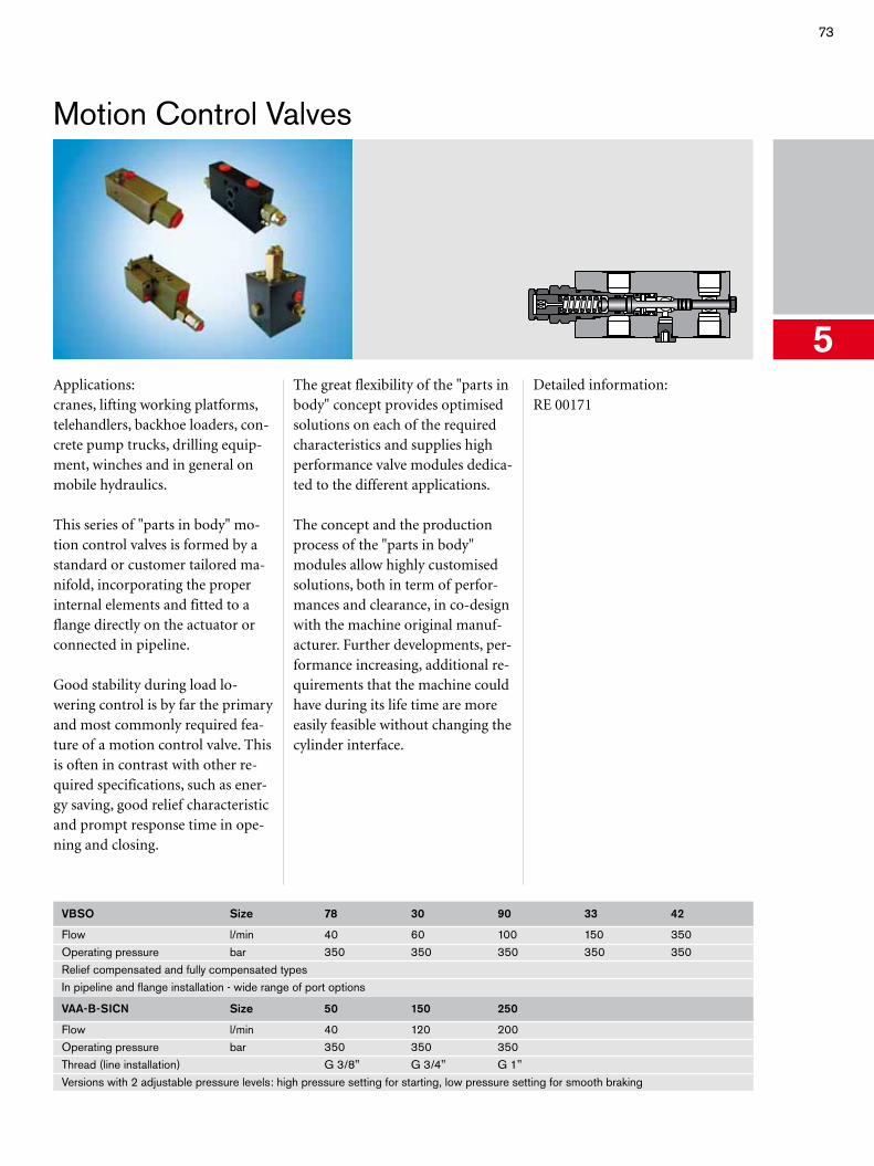
73
5
Motion Control Valves
Applications:cranes, lifting working platforms, telehandlers, backhoe loaders, con-crete pump trucks, drilling equip-ment, winches and in general on mobile hydraulics.
This series of "parts in body" mo-tion control valves is formed by a standard or customer tailored ma-nifold, incorporating the proper internal elements and fitted to a flange directly on the actuator or connected in pipeline.
Good stability during load lo-wering control is by far the primary and most commonly required fea-ture of a motion control valve. This is often in contrast with other re-quired specifications, such as ener-gy saving, good relief characteristic and prompt response time in ope-ning and closing.
The great flexibility of the "parts in body" concept provides optimised solutions on each of the required characteristics and supplies high performance valve modules dedica-ted to the different applications.
The concept and the production process of the "parts in body" modules allow highly customised solutions, both in term of perfor-mances and clearance, in co-design with the machine original manuf-acturer. Further developments, per-formance increasing, additional re-quirements that the machine could have during its life time are more easily feasible without changing the cylinder interface.
Detailed information:RE 00171
VBSO Size 78 30 90 33 42
Flow l/min 40 60 100 150 350Operating pressure bar 350 350 350 350 350Relief compensated and fully compensated typesIn pipeline and flange installation - wide range of port options
VAA-B-SICN Size 50 150 250
Flow l/min 40 120 200Operating pressure bar 350 350 350Thread (line installation) G 3/8" G 3/4" G 1"Versions with 2 adjustable pressure levels: high pressure setting for starting, low pressure setting for smooth braking
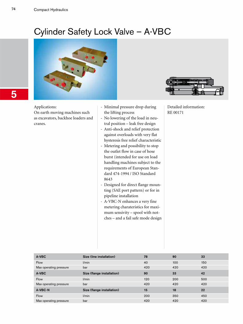
74
5
Compact Hydraulics
Cylinder Safety Lock Valve – A-VBC
Applications:On earth moving machines such as excavators, backhoe loaders and cranes.
- Minimal pressure drop during the lifting process
- No lowering of the load in neu-tral position – leak free design
- Anti-shock and relief protection against overloads with very flat hysteresis free relief characteristic
- Metering and possibility to stop the outlet flow in case of hose burst (intended for use on load handling machines subject to the requirements of European Stan-dard 474-1994 / ISO Standard 8643
- Designed for direct flange moun-ting (SAE port pattern) or for in pipeline installation
- A-VBC-N enhances a very fine metering charateristics for maxi-mum sensivity – spool with not-ches – and a fail safe mode design
Detailed information:RE 00171
A-VBC Size (line installation) 78 90 33
Flow l/min 40 100 150Max operating pressure bar 420 420 420
A-VBC Size (flange installation) 90 33 42
Flow l/min 120 200 500Max operating pressure bar 420 420 420
A-VBC-N Size (flange installation) 15 18 22
Flow l/min 200 350 450Max operating pressure bar 420 420 420
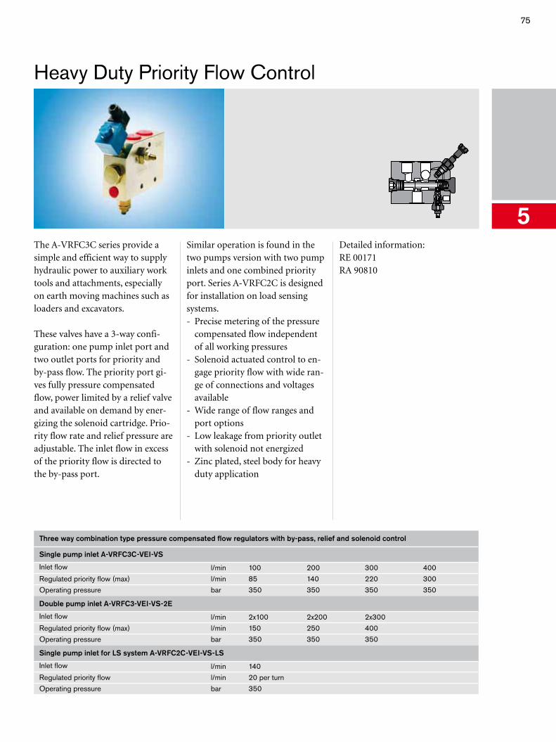
75
5
Heavy Duty Priority Flow Control
The A-VRFC3C series provide a simple and efficient way to supply hydraulic power to auxiliary work tools and attachments, especially on earth moving machines such as loaders and excavators.
These valves have a 3-way confi-guration: one pump inlet port and two outlet ports for priority and by-pass flow. The priority port gi-ves fully pressure compensated flow, power limited by a relief valve and available on demand by ener-gizing the solenoid cartridge. Prio-rity flow rate and relief pressure are adjustable. The inlet flow in excess of the priority flow is directed to the by-pass port.
Similar operation is found in the two pumps version with two pump inlets and one combined priority port. Series A-VRFC2C is designed for installation on load sensing systems.- Precise metering of the pressure
compensated flow independent of all working pressures
- Solenoid actuated control to en-gage priority flow with wide ran-ge of connections and voltages available
- Wide range of flow ranges and port options
- Low leakage from priority outlet with solenoid not energized
- Zinc plated, steel body for heavy duty application
Detailed information:RE 00171RA 90810
Three way combination type pressure compensated flow regulators with by-pass, relief and solenoid control
Single pump inlet A-VRFC3C-VEI-VS
Inlet flow l/min 100 200 300 400Regulated priority flow (max) l/min 85 140 220 300Operating pressure bar 350 350 350 350
Double pump inlet A-VRFC3-VEI-VS-2E
Inlet flow l/min 2x100 2x200 2x300Regulated priority flow (max) l/min 150 250 400Operating pressure bar 350 350 350
Single pump inlet for LS system A-VRFC2C-VEI-VS-LS
Inlet flow l/min 140Regulated priority flow l/min 20 per turnOperating pressure bar 350
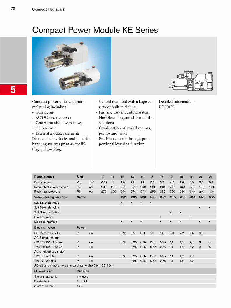
76
5
Compact Hydraulics
Compact Power Module KE Series
Compact power units with mini-mal piping including:- Gear pump- AC/DC electric motor- Central manifold with valves- Oil reservoir- External modular elementsDrive units in vehicles and material handling systems primary for lif-ting and lowering.
- Central manifold with a large va-riety of built in circuits
- Fast and easy mounting system- Flexible and expandable modular
solutions- Combination of several motors,
pumps and tanks- Precision control through pro-
portional lowering function
Detailed information:RE 00198
Pump group 1 Size 10 11 12 13 14 15 16 17 18 19 20 21
Displacement Vmax cm3 0,82 1,1 1,6 2,1 2,7 3,2 3,7 4,2 4,8 5,8 8,0 9,9Intermittent max. pressure P2 bar 230 230 230 230 230 210 210 210 190 190 160 150Peak max. pressure P3 bar 270 270 270 270 270 250 250 250 230 230 200 190
Valve housing versions Name M02 M03 M04 M05 M09 M15 M16 M19 M21 M25
2/2 Solenoid valve • • • •4/3 Solenoid valve • •3/2 Solenoid valve • •Start-up valve • •Modular interface • • • • • • • •Electric motors Power
DC motor 12V, 24V P kW 0,15 0,5 0,8 1,5 1,6 2,0 2,2 2,4 3,0AC 3-phase motor- 230/400V - 4 poles P kW 0,18 0,25 0,37 0,55 0,75 1,1 1,5 2,2 3 4- 230/400V - 2 poles P kW 0,25 0,37 0,55 0,75 1,1 1,5 2,2 3 4AC single-phase motor- 220V - 4 poles P kW 0,18 0,25 0,37 0,55 0,75 1,1 1,5 2,2- 220V - 2 poles P kW 0,25 0,37 0,55 0,75 1,1 1,5 2,2AC electric motors have standard frame size B14 (IEC 72-1)
Oil reservoir Capacity
Sheet metal tank 1 – 60 LPlastic tank 1 – 12 LAluminium tank 10 L
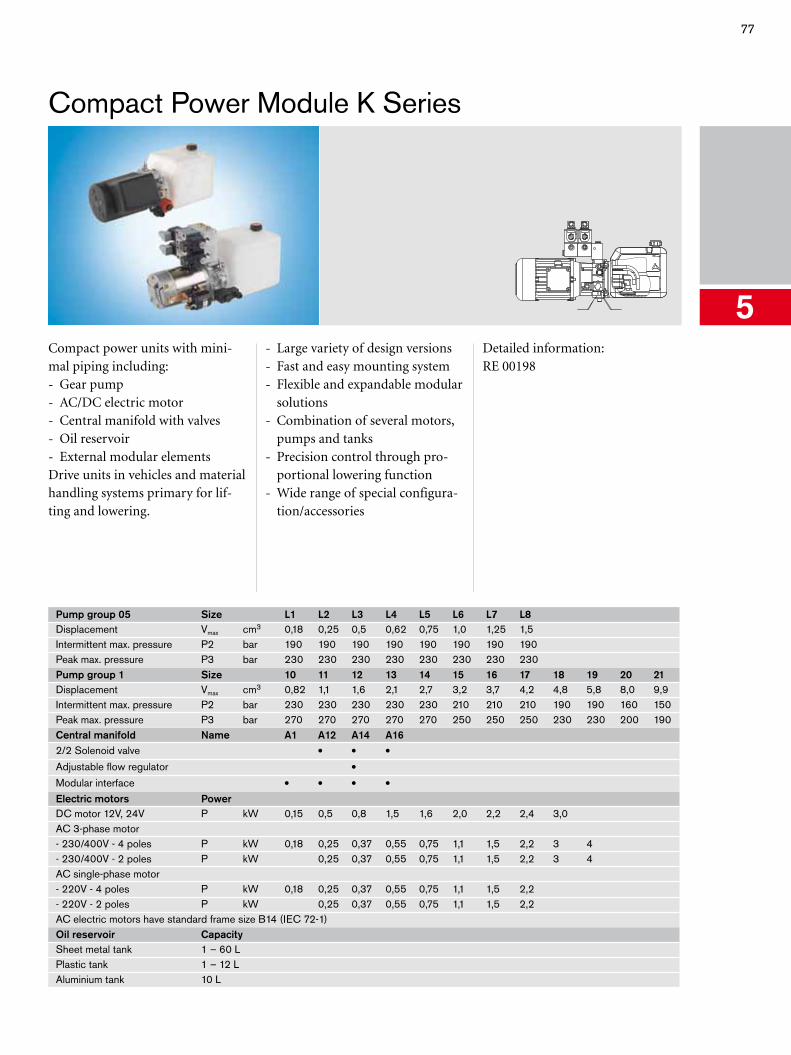
77
5
Compact Power Module K Series
Compact power units with mini-mal piping including:- Gear pump- AC/DC electric motor- Central manifold with valves- Oil reservoir- External modular elementsDrive units in vehicles and material handling systems primary for lif-ting and lowering.
- Large variety of design versions- Fast and easy mounting system- Flexible and expandable modular
solutions- Combination of several motors,
pumps and tanks- Precision control through pro-
portional lowering function- Wide range of special configura-
tion/accessories
Detailed information:RE 00198
Pump group 05 Size L1 L2 L3 L4 L5 L6 L7 L8Displacement Vmax cm3 0,18 0,25 0,5 0,62 0,75 1,0 1,25 1,5Intermittent max. pressure P2 bar 190 190 190 190 190 190 190 190Peak max. pressure P3 bar 230 230 230 230 230 230 230 230Pump group 1 Size 10 11 12 13 14 15 16 17 18 19 20 21Displacement Vmax cm3 0,82 1,1 1,6 2,1 2,7 3,2 3,7 4,2 4,8 5,8 8,0 9,9Intermittent max. pressure P2 bar 230 230 230 230 230 210 210 210 190 190 160 150Peak max. pressure P3 bar 270 270 270 270 270 250 250 250 230 230 200 190Central manifold Name A1 A12 A14 A162/2 Solenoid valve • • •Adjustable flow regulator •Modular interface • • • •Electric motors PowerDC motor 12V, 24V P kW 0,15 0,5 0,8 1,5 1,6 2,0 2,2 2,4 3,0AC 3-phase motor- 230/400V - 4 poles P kW 0,18 0,25 0,37 0,55 0,75 1,1 1,5 2,2 3 4- 230/400V - 2 poles P kW 0,25 0,37 0,55 0,75 1,1 1,5 2,2 3 4AC single-phase motor- 220V - 4 poles P kW 0,18 0,25 0,37 0,55 0,75 1,1 1,5 2,2- 220V - 2 poles P kW 0,25 0,37 0,55 0,75 1,1 1,5 2,2AC electric motors have standard frame size B14 (IEC 72-1)Oil reservoir CapacitySheet metal tank 1 – 60 LPlastic tank 1 – 12 LAluminium tank 10 L
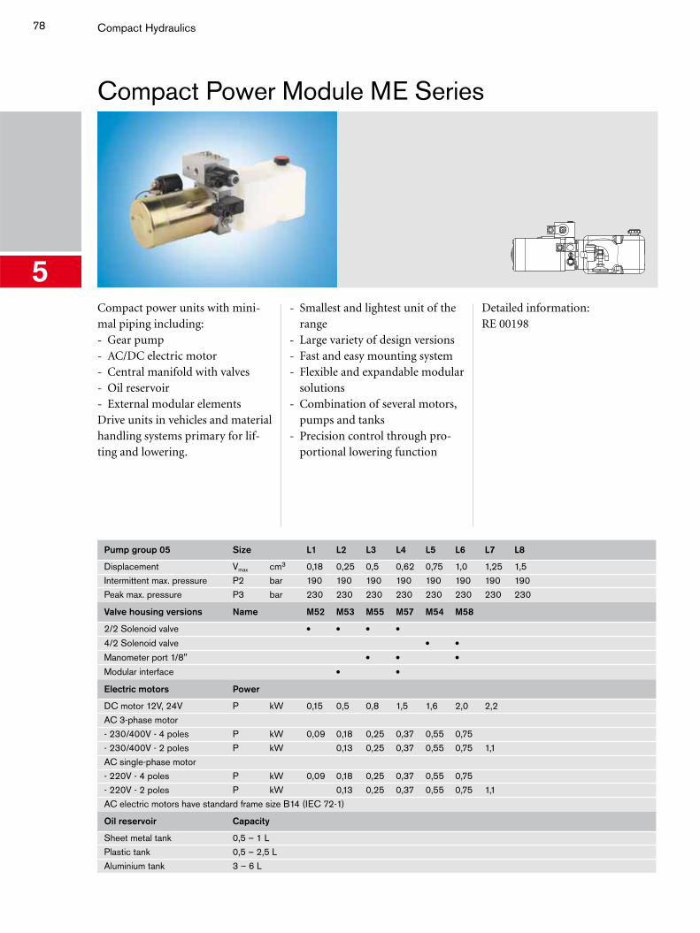
78
5
Compact Hydraulics
Compact Power Module ME Series
Compact power units with mini-mal piping including:- Gear pump- AC/DC electric motor- Central manifold with valves- Oil reservoir- External modular elementsDrive units in vehicles and material handling systems primary for lif-ting and lowering.
- Smallest and lightest unit of the range
- Large variety of design versions- Fast and easy mounting system- Flexible and expandable modular
solutions- Combination of several motors,
pumps and tanks- Precision control through pro-
portional lowering function
Detailed information:RE 00198
Pump group 05 Size L1 L2 L3 L4 L5 L6 L7 L8
Displacement Vmax cm3 0,18 0,25 0,5 0,62 0,75 1,0 1,25 1,5Intermittent max. pressure P2 bar 190 190 190 190 190 190 190 190Peak max. pressure P3 bar 230 230 230 230 230 230 230 230
Valve housing versions Name M52 M53 M55 M57 M54 M58
2/2 Solenoid valve • • • •4/2 Solenoid valve • •Manometer port 1/8" • • •Modular interface • •Electric motors Power
DC motor 12V, 24V P kW 0,15 0,5 0,8 1,5 1,6 2,0 2,2AC 3-phase motor- 230/400V - 4 poles P kW 0,09 0,18 0,25 0,37 0,55 0,75- 230/400V - 2 poles P kW 0,13 0,25 0,37 0,55 0,75 1,1AC single-phase motor- 220V - 4 poles P kW 0,09 0,18 0,25 0,37 0,55 0,75- 220V - 2 poles P kW 0,13 0,25 0,37 0,55 0,75 1,1AC electric motors have standard frame size B14 (IEC 72-1)
Oil reservoir Capacity
Sheet metal tank 0,5 – 1 LPlastic tank 0,5 – 2,5 LAluminium tank 3 – 6 L
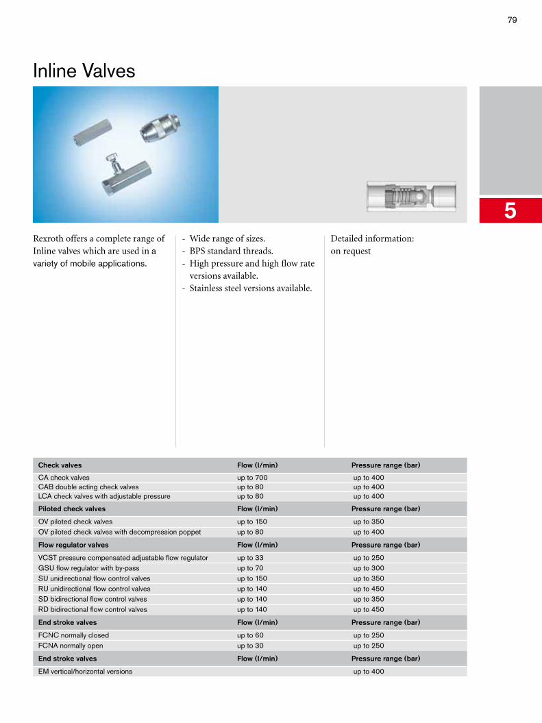
79
5
Inline Valves
Rexroth offers a complete range of Inline valves which are used in a variety of mobile applications.
- Wide range of sizes.- BPS standard threads. - High pressure and high flow rate
versions available.- Stainless steel versions available.
Detailed information:on request
Check valves Flow (l/min) Pressure range (bar)
CA check valves up to 700 up to 400CAB double acting check valves up to 80 up to 400LCA check valves with adjustable pressure up to 80 up to 400
Piloted check valves Flow (l/min) Pressure range (bar)
OV piloted check valves up to 150 up to 350OV piloted check valves with decompression poppet up to 80 up to 400
Flow regulator valves Flow (l/min) Pressure range (bar)
VCST pressure compensated adjustable flow regulator up to 33 up to 250GSU flow regulator with by-pass up to 70 up to 300SU unidirectional flow control valves up to 150 up to 350RU unidirectional flow control valves up to 140 up to 450SD bidirectional flow control valves up to 140 up to 350RD bidirectional flow control valves up to 140 up to 450
End stroke valves Flow (l/min) Pressure range (bar)
FCNC normally closed up to 60 up to 250FCNA normally open up to 30 up to 250
End stroke valves Flow (l/min) Pressure range (bar)
EM vertical/horizontal versions up to 400
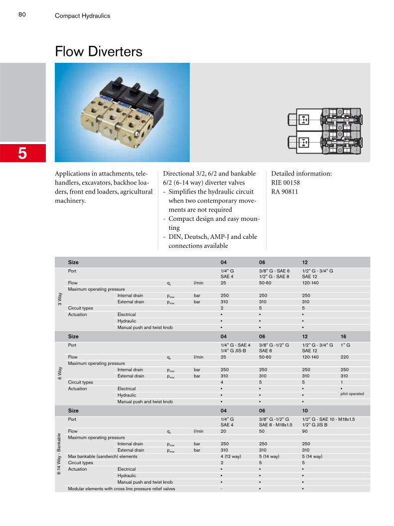
80
5
Compact Hydraulics
Flow Diverters
Applications in attachments, tele-handlers, excavators, backhoe loa-ders, front end loaders, agricultural machinery.
Directional 3/2, 6/2 and bankable 6/2 (6-14 way) diverter valves- Simplifies the hydraulic circuit
when two contemporary move-ments are not required
- Compact design and easy moun-ting
- DIN, Deutsch, AMP-J and cable connections available
Detailed information:RIE 00158RA 90811
Size 04 06 12
3 W
ay
Port 1/4" GSAE 4
3/8" G - SAE 61/2" G - SAE 8
1/2" G - 3/4" G SAE 12
Flow qv l/min 25 50-60 120-140Maximum operating pressure
Internal drain pmax bar 250 250 250External drain pmax bar 310 310 310
Circuit types 2 5 5Actuation Electrical • • •
Hydraulic • • •Manual push and twist knob • • •
Size 04 06 12 16
6 W
ay
Port 1/4" G - SAE 4 1/4" G JIS-B
3/8" G -1/2" GSAE 8
1/2" G - 3/4" G SAE 12
1" G
Flow qv l/min 25 50-60 120-140 220Maximum operating pressure
Internal drain pmax bar 250 250 250 250External drain pmax bar 310 310 310 310
Circuit types 4 5 5 1Actuation Electrical • • • •
pilot operatedHydraulic • • •Manual push and twist knob • • •
Size 04 06 10
6-14
Way
- B
anka
ble
Port 1/4" GSAE 4
3/8" G -1/2" G SAE 8 - M18x1.5
1/2" G - SAE 10 - M18x1.51/2" G JIS B
Flow qv l/min 20 50 90Maximum operating pressure
Internal drain pmax bar 250 250 250External drain pmax bar 310 310 310
Max bankable (sandwich) elements 4 (12 way) 5 (14 way) 5 (14 way)Circuit types 2 5 5Actuation Electrical • • •
Hydraulic • • •Manual push and twist knob • • •
Modular elements with cross line pressure relief valves - • •
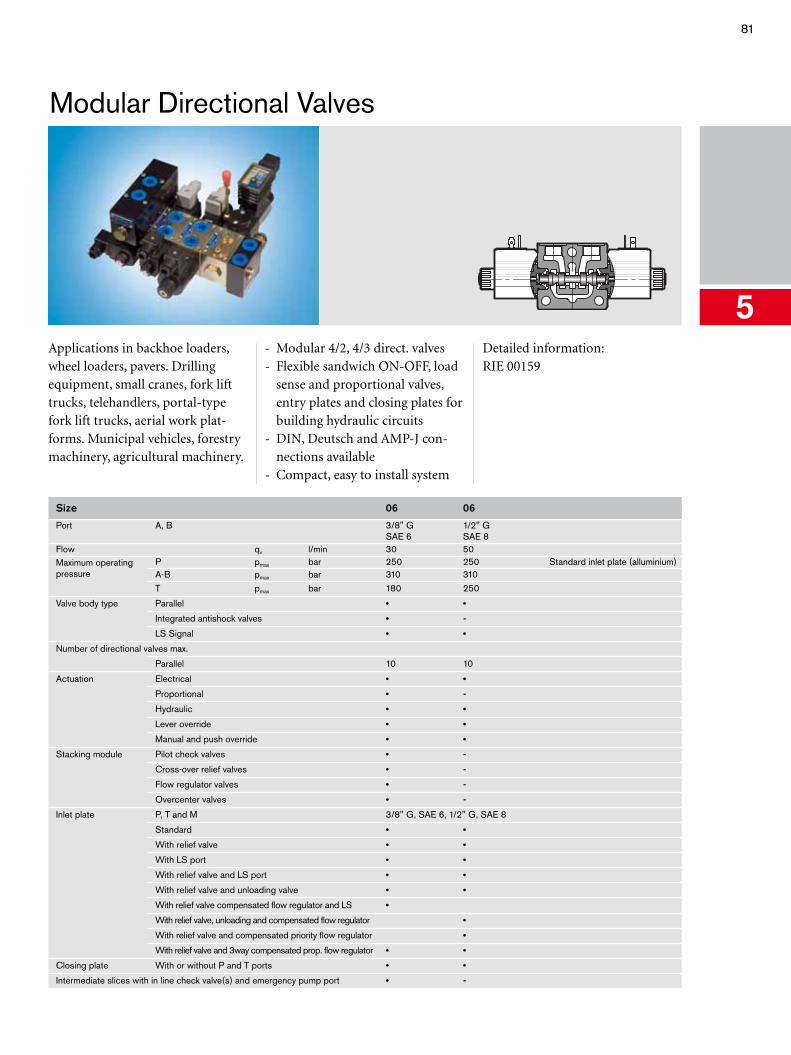
81
5
Modular Directional Valves
Applications in backhoe loaders, wheel loaders, pavers. Drilling equipment, small cranes, fork lift trucks, telehandlers, portal-type fork lift trucks, aerial work plat-forms. Municipal vehicles, forestry machinery, agricultural machinery.
- Modular 4/2, 4/3 direct. valves- Flexible sandwich ON-OFF, load
sense and proportional valves, entry plates and closing plates for building hydraulic circuits
- DIN, Deutsch and AMP-J con-nections available
- Compact, easy to install system
Detailed information:RIE 00159
Size 06 06
Port A, B 3/8" GSAE 6
1/2" GSAE 8
Flow qv l/min 30 50Maximum operating pressure
P pmax bar 250 250 Standard inlet plate (alluminium)A-B pmax bar 310 310T pmax bar 180 250
Valve body type Parallel • •
Integrated antishock valves • -
LS Signal • •
Number of directional valves max.
Parallel 10 10
Actuation Electrical • •
Proportional • -
Hydraulic • •
Lever override • •
Manual and push override • •
Stacking module Pilot check valves • -
Cross-over relief valves • -
Flow regulator valves • -
Overcenter valves • -
Inlet plate P, T and M 3/8" G, SAE 6, 1/2" G, SAE 8
Standard • •
With relief valve • •
With LS port • •
With relief valve and LS port • •
With relief valve and unloading valve • •
With relief valve compensated flow regulator and LS •
With relief valve, unloading and compensated flow regulator •
With relief valve and compensated priority flow regulator •
With relief valve and 3way compensated prop. flow regulator • •
Closing plate With or without P and T ports • •
Intermediate slices with in line check valve(s) and emergency pump port • -
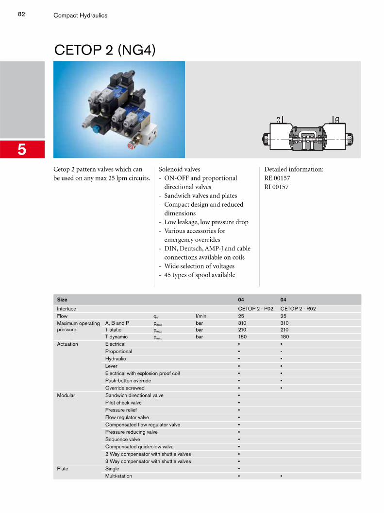
82
5
Compact Hydraulics
CETOP 2 (NG4)
Cetop 2 pattern valves which can be used on any max 25 lpm circuits.
Solenoid valves- ON-OFF and proportional
directional valves- Sandwich valves and plates- Compact design and reduced
dimensions- Low leakage, low pressure drop- Various accessories for
emergency overrides- DIN, Deutsch, AMP-J and cable
connections available on coils- Wide selection of voltages- 45 types of spool available
Detailed information:RE 00157RI 00157
Size 04 04
Interface CETOP 2 - P02 CETOP 2 - R02Flow qv l/min 25 25Maximum operating pressure
A, B and P pmax bar 310 310T static pmax bar 210 210T dynamic pmax bar 180 180
Actuation Electrical • •Proportional • -Hydraulic • •Lever • •Electrical with explosion proof coil • •Push-botton override • •Override screwed • •
Modular Sandwich directional valve •Pilot check valve •Pressure relief •Flow regulator valve •Compensated flow regulator valve •Pressure reducing valve •Sequence valve •Compensated quick-slow valve •2 Way compensator with shuttle valves •3 Way compensator with shuttle valves •
Plate Single •Multi-station • •
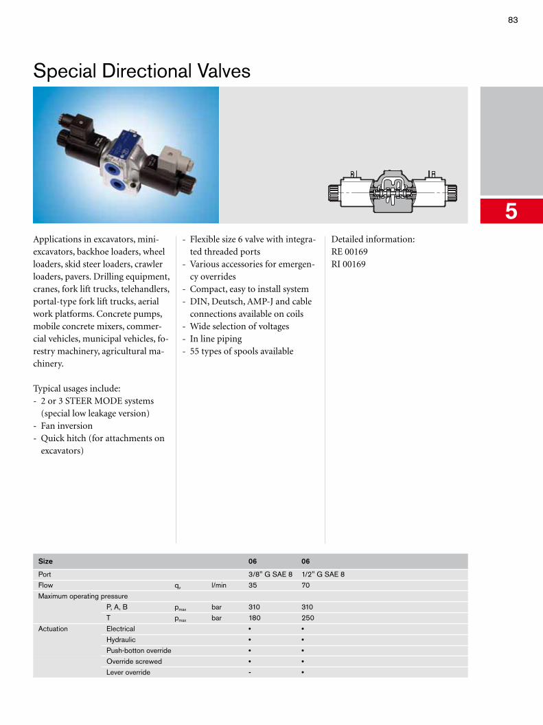
83
5
Special Directional Valves
Applications in excavators, mini-excavators, backhoe loaders, wheel loaders, skid steer loaders, crawler loaders, pavers. Drilling equipment, cranes, fork lift trucks, telehandlers, portal-type fork lift trucks, aerial work platforms. Concrete pumps, mobile concrete mixers, commer-cial vehicles, municipal vehicles, fo-restry machinery, agricultural ma-chinery.
Typical usages include:- 2 or 3 STEER MODE systems
(special low leakage version)- Fan inversion- Quick hitch (for attachments on
excavators)
- Flexible size 6 valve with integra-ted threaded ports
- Various accessories for emergen-cy overrides
- Compact, easy to install system- DIN, Deutsch, AMP-J and cable
connections available on coils- Wide selection of voltages- In line piping- 55 types of spools available
Detailed information:RE 00169RI 00169
Size 06 06
Port 3/8" G SAE 8 1/2" G SAE 8Flow qv l/min 35 70Maximum operating pressure
P, A, B pmax bar 310 310T pmax bar 180 250
Actuation Electrical • •Hydraulic • •Push-botton override • •Override screwed • •Lever override - •

84
5
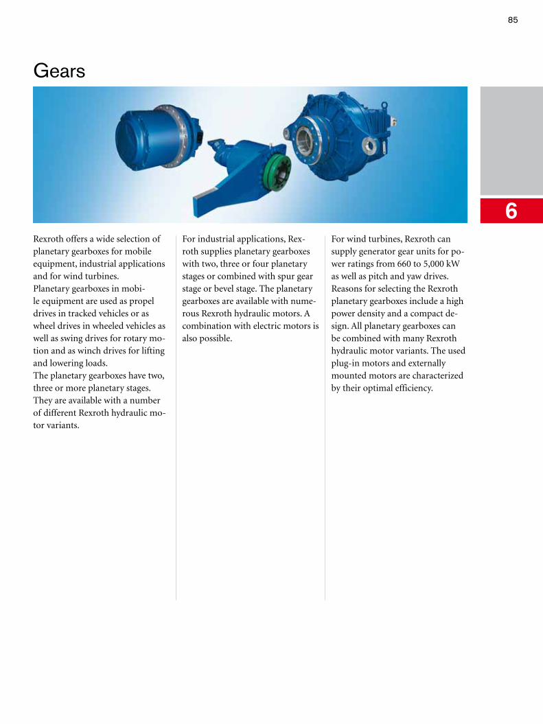
85
Gears
6Rexroth offers a wide selection of planetary gearboxes for mobile equipment, industrial applications and for wind turbines.Planetary gearboxes in mobi-le equipment are used as propel drives in tracked vehicles or as wheel drives in wheeled vehicles as well as swing drives for rotary mo-tion and as winch drives for lifting and lowering loads.The planetary gearboxes have two, three or more planetary stages. They are available with a number of different Rexroth hydraulic mo-tor variants.
For industrial applications, Rex-roth supplies planetary gearboxes with two, three or four planetary stages or combined with spur gear stage or bevel stage. The planetary gearboxes are available with nume-rous Rexroth hydraulic motors. A combination with electric motors is also possible.
For wind turbines, Rexroth can supply generator gear units for po-wer ratings from 660 to 5,000 kW as well as pitch and yaw drives.Reasons for selecting the Rexroth planetary gearboxes include a high power density and a compact de-sign. All planetary gearboxes can be combined with many Rexroth hydraulic motor variants. The used plug-in motors and externally mounted motors are characterized by their optimal efficiency.
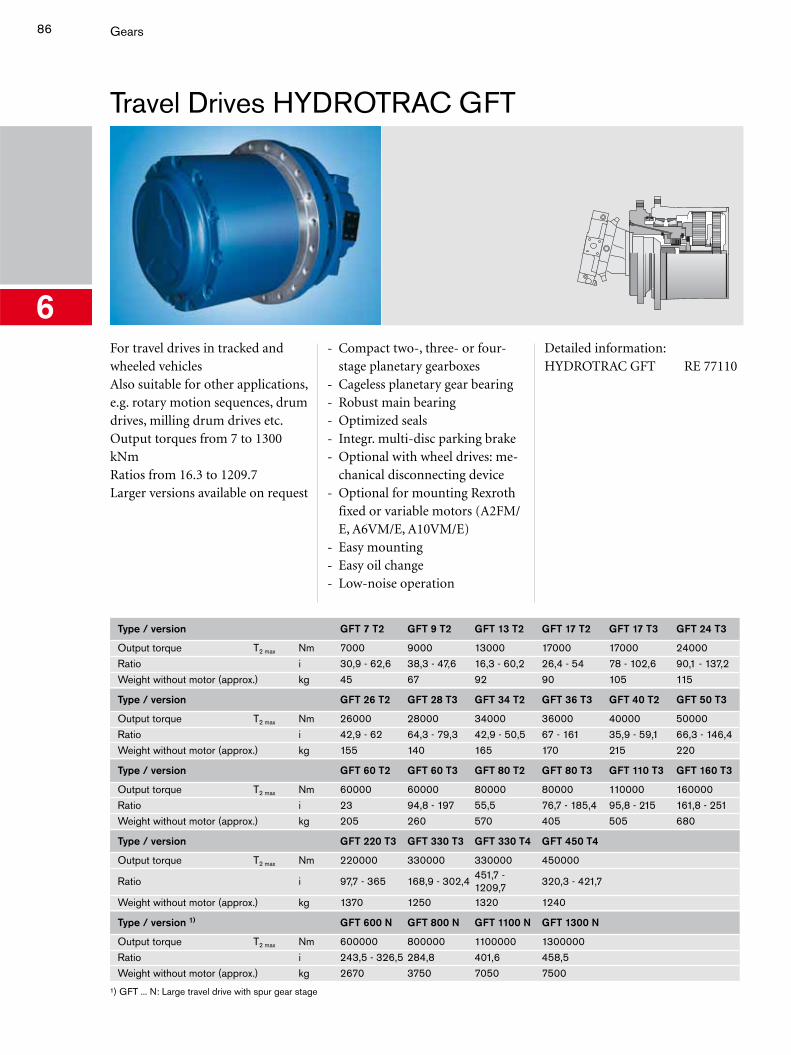
86 Gears
Travel Drives HYDROTRAC GFT
6For travel drives in tracked and wheeled vehiclesAlso suitable for other applications, e.g. rotary motion sequences, drum drives, milling drum drives etc.Output torques from 7 to 1300 kNmRatios from 16.3 to 1209.7Larger versions available on request
- Compact two-, three- or four-stage planetary gearboxes
- Cageless planetary gear bearing- Robust main bearing- Optimized seals- Integr. multi-disc parking brake- Optional with wheel drives: me-
chanical disconnecting device- Optional for mounting Rexroth
fixed or variable motors (A2FM/E, A6VM/E, A10VM/E)
- Easy mounting- Easy oil change- Low-noise operation
Detailed information:HYDROTRAC GFT RE 77110
Type / version GFT 7 T2 GFT 9 T2 GFT 13 T2 GFT 17 T2 GFT 17 T3 GFT 24 T3
Output torque T2 max Nm 7000 9000 13000 17000 17000 24000Ratio i 30,9 - 62,6 38,3 - 47,6 16,3 - 60,2 26,4 - 54 78 - 102,6 90,1 - 137,2Weight without motor (approx.) kg 45 67 92 90 105 115
Type / version GFT 26 T2 GFT 28 T3 GFT 34 T2 GFT 36 T3 GFT 40 T2 GFT 50 T3
Output torque T2 max Nm 26000 28000 34000 36000 40000 50000Ratio i 42,9 - 62 64,3 - 79,3 42,9 - 50,5 67 - 161 35,9 - 59,1 66,3 - 146,4Weight without motor (approx.) kg 155 140 165 170 215 220
Type / version GFT 60 T2 GFT 60 T3 GFT 80 T2 GFT 80 T3 GFT 110 T3 GFT 160 T3
Output torque T2 max Nm 60000 60000 80000 80000 110000 160000Ratio i 23 94,8 - 197 55,5 76,7 - 185,4 95,8 - 215 161,8 - 251Weight without motor (approx.) kg 205 260 570 405 505 680
Type / version GFT 220 T3 GFT 330 T3 GFT 330 T4 GFT 450 T4
Output torque T2 max Nm 220000 330000 330000 450000
Ratio i 97,7 - 365 168,9 - 302,4451,7 - 1209,7
320,3 - 421,7
Weight without motor (approx.) kg 1370 1250 1320 1240
Type / version 1) GFT 600 N GFT 800 N GFT 1100 N GFT 1300 N
Output torque T2 max Nm 600000 800000 1100000 1300000Ratio i 243,5 - 326,5 284,8 401,6 458,5Weight without motor (approx.) kg 2670 3750 7050 7500
¹) GFT ... N: Large travel drive with spur gear stage
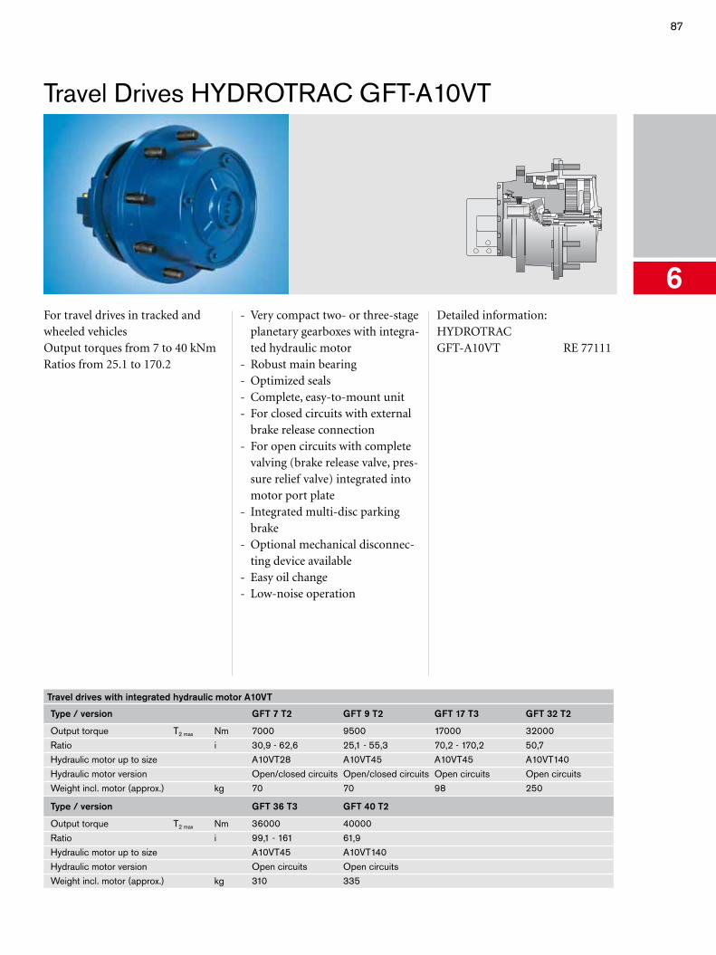
87
Travel Drives HYDROTRAC GFT-A10VT
6For travel drives in tracked and wheeled vehiclesOutput torques from 7 to 40 kNmRatios from 25.1 to 170.2
- Very compact two- or three-stage planetary gearboxes with integra-ted hydraulic motor
- Robust main bearing- Optimized seals- Complete, easy-to-mount unit- For closed circuits with external
brake release connection- For open circuits with complete
valving (brake release valve, pres-sure relief valve) integrated into motor port plate
- Integrated multi-disc parking brake
- Optional mechanical disconnec-ting device available
- Easy oil change- Low-noise operation
Detailed information:HYDROTRAC GFT-A10VT RE 77111
Travel drives with integrated hydraulic motor A10VT
Type / version GFT 7 T2 GFT 9 T2 GFT 17 T3 GFT 32 T2
Output torque T2 max Nm 7000 9500 17000 32000Ratio i 30,9 - 62,6 25,1 - 55,3 70,2 - 170,2 50,7Hydraulic motor up to size A10VT28 A10VT45 A10VT45 A10VT140Hydraulic motor version Open/closed circuits Open/closed circuits Open circuits Open circuitsWeight incl. motor (approx.) kg 70 70 98 250
Type / version GFT 36 T3 GFT 40 T2
Output torque T2 max Nm 36000 40000Ratio i 99,1 - 161 61,9Hydraulic motor up to size A10VT45 A10VT140Hydraulic motor version Open circuits Open circuitsWeight incl. motor (approx.) kg 310 335
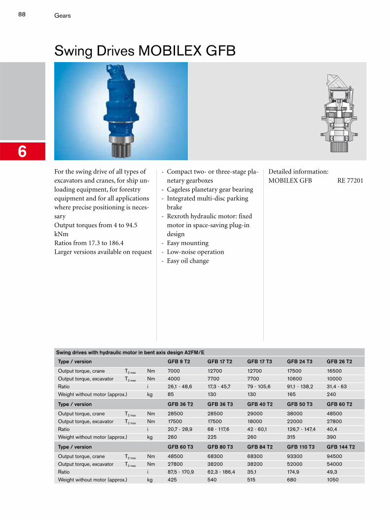
88 Gears
Swing Drives MOBILEX GFB
6For the swing drive of all types of excavators and cranes, for ship un-loading equipment, for forestry equipment and for all applications where precise positioning is neces-saryOutput torques from 4 to 94.5 kNmRatios from 17.3 to 186.4Larger versions available on request
- Compact two- or three-stage pla-netary gearboxes
- Cageless planetary gear bearing- Integrated multi-disc parking
brake- Rexroth hydraulic motor: fixed
motor in space-saving plug-in design
- Easy mounting- Low-noise operation- Easy oil change
Detailed information:MOBILEX GFB RE 77201
Swing drives with hydraulic motor in bent axis design A2FM/E
Type / version GFB 9 T2 GFB 17 T2 GFB 17 T3 GFB 24 T3 GFB 26 T2
Output torque, crane T2 max Nm 7000 12700 12700 17500 16500Output torque, excavator T2 max Nm 4000 7700 7700 10600 10000Ratio i 26,1 - 48,6 17,3 - 45,7 79 - 105,6 91,1 - 138,2 31,4 - 63Weight without motor (approx.) kg 85 130 130 165 240
Type / version GFB 36 T2 GFB 36 T3 GFB 40 T2 GFB 50 T3 GFB 60 T2
Output torque, crane T2 max Nm 28500 28500 29000 38000 48500Output torque, excavator T2 max Nm 17500 17500 18000 22000 27800Ratio i 20,7 - 28,9 68 - 117,6 42 - 60,1 126,7 - 147,4 40,4Weight without motor (approx.) kg 260 225 260 315 390
Type / version GFB 60 T3 GFB 80 T3 GFB 84 T2 GFB 110 T3 GFB 144 T2
Output torque, crane T2 max Nm 48500 68300 68300 93300 94500Output torque, excavator T2 max Nm 27800 38200 38200 52000 54000Ratio i 87,5 - 170,9 62,3 - 186,4 35,1 174,9 49,3Weight without motor (approx.) kg 425 540 515 680 1050
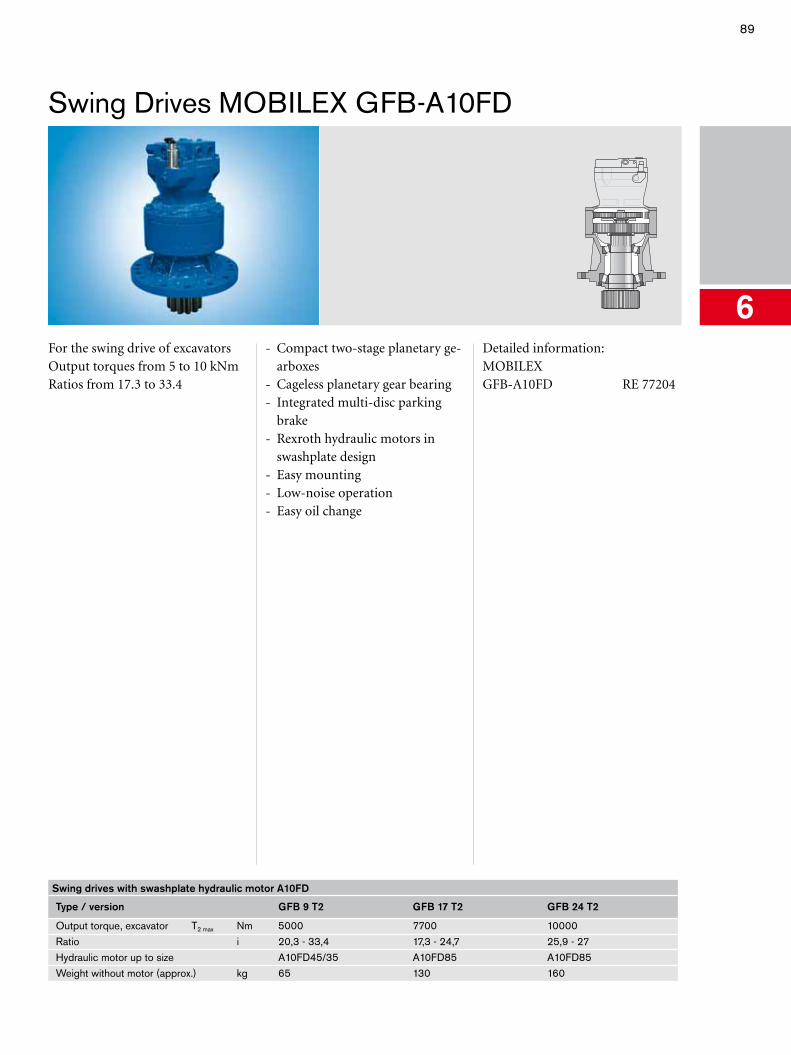
89
Swing Drives MOBILEX GFB-A10FD
6For the swing drive of excavatorsOutput torques from 5 to 10 kNmRatios from 17.3 to 33.4
- Compact two-stage planetary ge-arboxes
- Cageless planetary gear bearing- Integrated multi-disc parking
brake- Rexroth hydraulic motors in
swashplate design- Easy mounting- Low-noise operation- Easy oil change
Detailed information:MOBILEX GFB-A10FD RE 77204
Swing drives with swashplate hydraulic motor A10FD
Type / version GFB 9 T2 GFB 17 T2 GFB 24 T2
Output torque, excavator T2 max Nm 5000 7700 10000Ratio i 20,3 - 33,4 17,3 - 24,7 25,9 - 27Hydraulic motor up to size A10FD45/35 A10FD85 A10FD85Weight without motor (approx.) kg 65 130 160
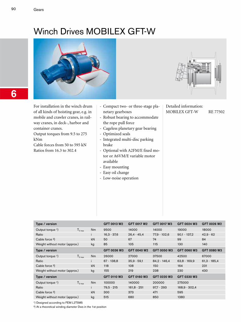
90 Gears
Winch Drives MOBILEX GFT-W
6For installation in the winch drum of all kinds of hoisting gear, e.g. in mobile and crawler cranes, in rail-way cranes, in deck-, harbor and container cranes.Output torques from 9.5 to 275 kNmCable forces from 50 to 595 kNRatios from 16.3 to 302.4
- Compact two- or three-stage pla-netary gearboxes
- Robust bearing to accommodate the rope pull force
- Cageless planetary gear bearing- Optimized seals- Integrated multi-disc parking
brake- Optional with A2FM/E fixed mo-
tor or A6VM/E variable motor available
- Easy mounting- Easy oil change- Low-noise operation
Detailed information:MOBILEX GFT-W RE 77502
Type / version GFT 0013 W2 GFT 0017 W2 GFT 0017 W3 GFT 0024 W3 GFT 0026 W2
Output torque ¹) T2 max Nm 9500 14000 14000 19000 18000Ratio i 16,3 - 37,6 26,4 - 45,4 77,9 - 102,6 90,1 - 137,2 42,9 - 62Cable force ²) kN 50 67 74 99 84Weight without motor (approx.) kg 85 105 115 130 140
Type / version GFT 0036 W3 GFT 0040 W2 GFT 0050 W3 GFT 0060 W3 GFT 0080 W3
Output torque ¹) T2 max Nm 26000 27000 37500 42500 67000Ratio i 67 - 138,8 35,9 - 59,1 84,2 - 146,4 63,8 - 169,9 61,3 - 185,4Cable force ²) kN 118 108 150 164 231Weight without motor (approx.) kg 155 219 238 230 430
Type / version GFT 0110 W3 GFT 0160 W3 GFT 0220 W3 GFT 0330 W3
Output torque ¹) T2 max Nm 100000 140000 200000 275000Ratio i 79,5 - 215 161,8 - 251 97,7 - 293 168,9 - 302,4Cable force ²) kN 300 373 471 595Weight without motor (approx.) kg 515 680 850 1380
¹) Designed according to FEM L2T5M5²) At a theoretical winding diameter Dws in the 1st position
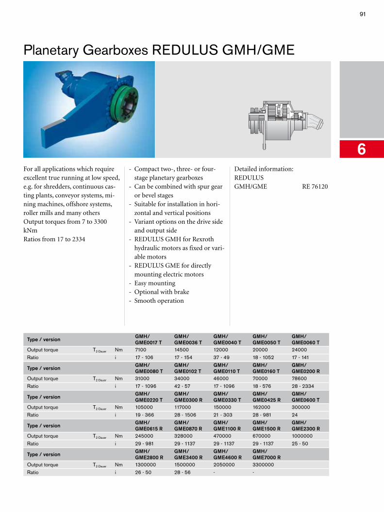
91
Planetary Gearboxes REDULUS GMH/GME
6For all applications which require excellent true running at low speed, e.g. for shredders, continuous cas-ting plants, conveyor systems, mi-ning machines, offshore systems, roller mills and many othersOutput torques from 7 to 3300 kNmRatios from 17 to 2334
- Compact two-, three- or four-stage planetary gearboxes
- Can be combined with spur gear or bevel stages
- Suitable for installation in hori-zontal and vertical positions
- Variant options on the drive side and output side
- REDULUS GMH for Rexroth hydraulic motors as fixed or vari-able motors
- REDULUS GME for directly mounting electric motors
- Easy mounting- Optional with brake- Smooth operation
Detailed information:REDULUS GMH/GME RE 76120
Type / version GMH/GME0017 T
GMH/GME0036 T
GMH/GME0040 T
GMH/GME0050 T
GMH/GME0060 T
Output torque T2 Dauer Nm 7100 14500 12000 20000 24000Ratio i 17 - 106 17 - 154 37 - 49 18 - 1052 17 - 141
Type / version GMH/GME0080 T
GMH/GME0102 T
GMH/GME0110 T
GMH/GME0160 T
GMH/GME0200 R
Output torque T2 Dauer Nm 31000 34000 46000 70000 78600Ratio i 17 - 1096 42 - 57 17 - 1096 18 - 576 28 - 2334
Type / version GMH/GME0220 T
GMH/GME0300 R
GMH/GME0330 T
GMH/GME0425 R
GMH/GME0600 T
Output torque T2 Dauer Nm 105000 117000 150000 162000 300000Ratio i 19 - 366 28 - 1506 21 - 303 28 - 981 24
Type / version GMH/GME0615 R
GMH/GME0870 R
GMH/GME1100 R
GMH/GME1500 R
GMH/GME2300 R
Output torque T2 Dauer Nm 245000 328000 470000 670000 1000000Ratio i 29 - 981 29 - 1137 29 - 1137 29 - 1137 25 - 50
Type / version GMH/GME2800 R
GMH/GME3400 R
GMH/GME4600 R
GMH/GME7000 R
Output torque T2 Dauer Nm 1300000 1500000 2050000 3300000Ratio i 26 - 50 28 - 56 - -
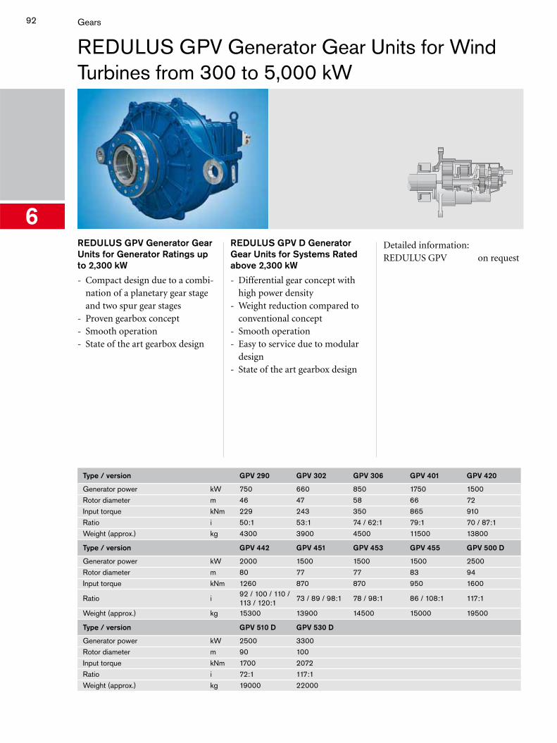
92 Gears
REDULUS GPV Generator Gear Units for Wind Turbines from 300 to 5,000 kW
6REDULUS GPV Generator Gear Units for Generator Ratings up to 2,300 kW
- Compact design due to a combi-nation of a planetary gear stage and two spur gear stages
- Proven gearbox concept- Smooth operation- State of the art gearbox design
REDULUS GPV D Generator Gear Units for Systems Rated above 2,300 kW
- Differential gear concept with high power density
- Weight reduction compared to conventional concept
- Smooth operation- Easy to service due to modular
design- State of the art gearbox design
Detailed information:REDULUS GPV on request
Type / version GPV 290 GPV 302 GPV 306 GPV 401 GPV 420
Generator power kW 750 660 850 1750 1500Rotor diameter m 46 47 58 66 72Input torque kNm 229 243 350 865 910Ratio i 50:1 53:1 74 / 62:1 79:1 70 / 87:1Weight (approx.) kg 4300 3900 4500 11500 13800
Type / version GPV 442 GPV 451 GPV 453 GPV 455 GPV 500 D
Generator power kW 2000 1500 1500 1500 2500Rotor diameter m 80 77 77 83 94Input torque kNm 1260 870 870 950 1600
Ratio i92 / 100 / 110 / 113 / 120:1
73 / 89 / 98:1 78 / 98:1 86 / 108:1 117:1
Weight (approx.) kg 15300 13900 14500 15000 19500
Type / version GPV 510 D GPV 530 D
Generator power kW 2500 3300Rotor diameter m 90 100Input torque kNm 1700 2072Ratio i 72:1 117:1Weight (approx.) kg 19000 22000
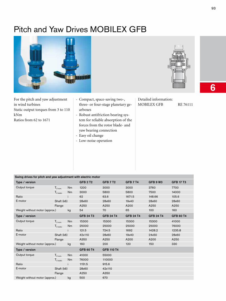
93
Pitch and Yaw Drives MOBILEX GFB
6For the pitch and yaw adjustment in wind turbinesStatic output torques from 3 to 110 kNmRatios from 62 to 1671
- Compact, space-saving two-, three- or four-stage planetary ge-arboxes
- Robust antifriction bearing sys-tem for reliable absorption of the forces from the rotor blade- and yaw bearing connection
- Easy oil change- Low-noise operation
Detailed information:MOBILEX GFB RE 76111
Swing drives for pitch and yaw adjustment with electric motor
Type / version GFB 2 T2 GFB 7 T2 GFB 7 T4 GFB 9 W3 GFB 17 T3
Output torque T2 nom. Nm 1200 3000 3000 3760 7700T2 static Nm 3000 5800 5800 7500 14000
Ratio i 62 63.6 1671.5 148.66 105.6E-motor Shaft (k6) 28x60 28x60 19x40 28x60 28x60
Flange A250 A250 A200 A250 A250Weight without motor (approx.) kg 54 70 65 100 160
Type / version GFB 24 T3 GFB 24 T4 GFB 24 T4 GFB 24 T4 GFB 60 T4
Output torque T2 nom. Nm 15300 15300 15300 15300 41000T2 static Nm 25000 25000 25000 25000 76000
Ratio i 121.5 724.5 1692 1428.2 1235.8E-motor Shaft (k6) 42x110 28x60 19x40 24x50 28x60
Flange A350 A250 A200 A200 A250Weight without motor (approx.) kg 160 200 120 150 330
Type / version GFB 60 T4 GFB 110 T4
Output torque T2 nom. Nm 41000 55000T2 static Nm 76000 110000
Ratio i 1151.5 915.6E-motor Shaft (k6) 28x60 42x110
Flange A250 A350Weight without motor (approx.) kg 500 670

94
6
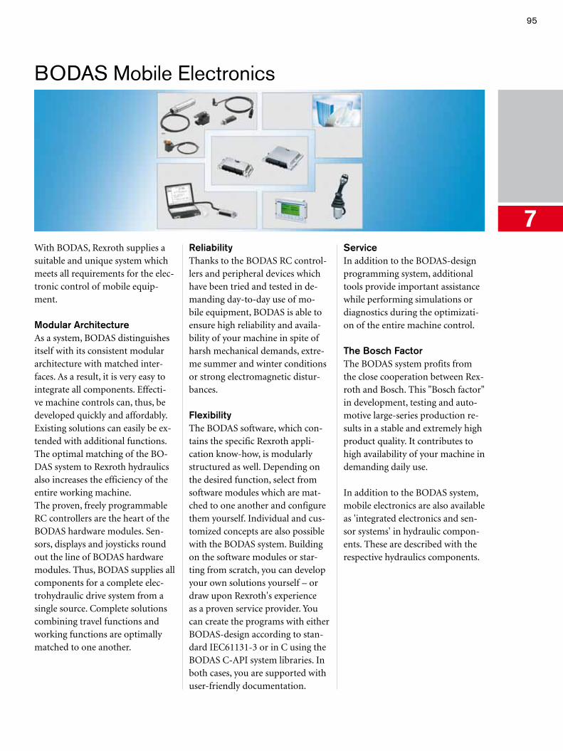
95
BODAS Mobile Electronics
7With BODAS, Rexroth supplies a suitable and unique system which meets all requirements for the elec-tronic control of mobile equip-ment.
Modular ArchitectureAs a system, BODAS distinguishes itself with its consistent modular architecture with matched inter-faces. As a result, it is very easy to integrate all components. Effecti-ve machine controls can, thus, be developed quickly and affordably. Existing solutions can easily be ex-tended with additional functions. The optimal matching of the BO-DAS system to Rexroth hydraulics also increases the efficiency of the entire working machine.The proven, freely programmable RC controllers are the heart of the BODAS hardware modules. Sen-sors, displays and joysticks round out the line of BODAS hardware modules. Thus, BODAS supplies all components for a complete elec-trohydraulic drive system from a single source. Complete solutions combining travel functions and working functions are optimally matched to one another.
ReliabilityThanks to the BODAS RC control-lers and peripheral devices which have been tried and tested in de-manding day-to-day use of mo-bile equipment, BODAS is able to ensure high reliability and availa-bility of your machine in spite of harsh mechanical demands, extre-me summer and winter conditions or strong electromagnetic distur-bances.
FlexibilityThe BODAS software, which con-tains the specific Rexroth appli-cation know-how, is modularly structured as well. Depending on the desired function, select from software modules which are mat-ched to one another and configure them yourself. Individual and cus-tomized concepts are also possible with the BODAS system. Building on the software modules or star-ting from scratch, you can develop your own solutions yourself – or draw upon Rexroth's experience as a proven service provider. You can create the programs with either BODAS-design according to stan-dard IEC61131-3 or in C using the BODAS C-API system libraries. In both cases, you are supported with user-friendly documentation.
ServiceIn addition to the BODAS-design programming system, additional tools provide important assistance while performing simulations or diagnostics during the optimizati-on of the entire machine control.
The Bosch FactorThe BODAS system profits from the close cooperation between Rex-roth and Bosch. This "Bosch factor" in development, testing and auto-motive large-series production re-sults in a stable and extremely high product quality. It contributes to high availability of your machine in demanding daily use.
In addition to the BODAS system, mobile electronics are also available as 'integrated electronics and sen-sor systems' in hydraulic compon-ents. These are described with the respective hydraulics components.
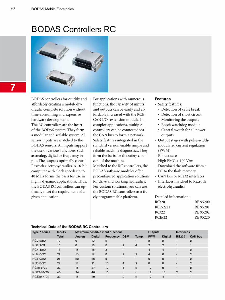
96 BODAS Mobile Electronics
BODAS Controllers RC
7BODAS controllers for quickly and affordably creating a mobile-hy-draulic complete solution without time-consuming and expensive hardware development. The RC controllers are the heart of the BODAS system. They form a modular and scalable system. All sensor inputs are matched to the BODAS sensors. All inputs support the use of various functions, such as analog, digital or frequency in-put. The outputs optimally control Rexroth electrohydraulics. A 16-bit computer with clock speeds up to 40 MHz forms the basis for use in highly dynamic applications. Thus, the BODAS RC controllers can op-timally meet the requirement of a given application.
For applications with numerous functions, the capacity of inputs and outputs can be easily and af-fordably increased with the RCE CAN I/O- extension module. In complex applications, multiple controllers can be connected via the CAN bus to form a network. Safety features integrated in the standard version enable simple and reliable machine diagnostics. They form the basis for the safety con-cept of the machine.Matched to the RC controllers, the BODAS software modules offer preconfigured application solutions for drive and working hydraulics. For custom solutions, you can use the BODAS RC controllers as a fre-ely programmable platform.
Features- Safety features: • Detection of cable break • Detection of short circuit • Monitoring the outputs • Bosch watchdog module • Central switch for all power
outputs- Output stages with pulse-width-
modulated current regulation (PWM)
- Robust case - High EMC > 100 V/m - Download the software from a
PC to the flash memory- CAN bus or RS232 interfaces - Interfaces matched to Rexroth
electrohydraulics
Detailed information:RC/20 RE 95200RC2-2/21 RE 95201RC/22 RE 95202RCE/22 RE 95220
Technical Data of the BODAS RC ControllersType / series Inputs Maximum possible input functions Outputs Interfaces
Total Analog Digital Frequency DSM Temp. PWM Digital RS232 CAN busRC2-2/20 10 6 10 2 - - 2 2 1 2RC2-2/21 16 8 16 8 2 4 2 2 1 1RC4-4/20 18 15 18 3 - - 4 4 1 2RC4-6/22 21 10 17 8 2 2 4 6 - 2RC6-9/20 25 20 25 5 - - 6 9 1 2RC8-8/22 27 12 21 10 4 2 8 8 - 2RC12-8/22 33 15 27 10 4 2 12 8 - 2RC12-18/20 46 24 46 10 - - 12 18 2 2RCE12-4/22 33 15 29 - 2 2 12 4 - 1
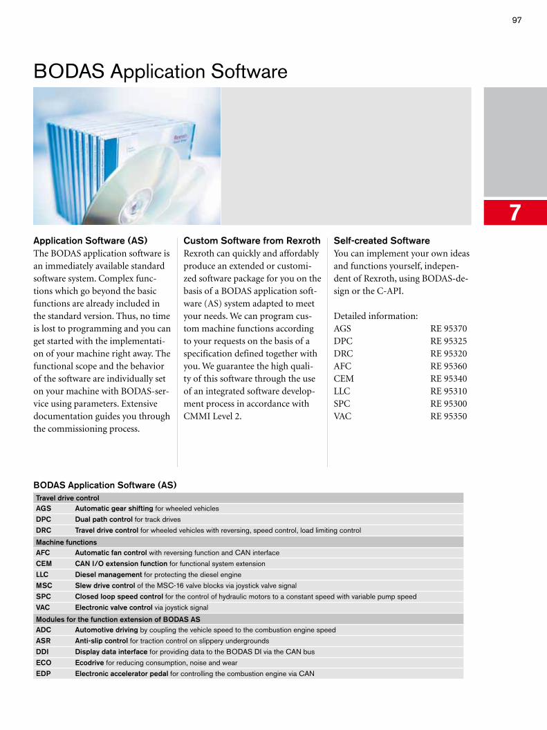
97
BODAS Application Software
7Application Software (AS)The BODAS application software is an immediately available standard software system. Complex func-tions which go beyond the basic functions are already included in the standard version. Thus, no time is lost to programming and you can get started with the implementati-on of your machine right away. The functional scope and the behavior of the software are individually set on your machine with BODAS-ser-vice using parameters. Extensive documentation guides you through the commissioning process.
Custom Software from RexrothRexroth can quickly and affordably produce an extended or customi-zed software package for you on the basis of a BODAS application soft-ware (AS) system adapted to meet your needs. We can program cus-tom machine functions according to your requests on the basis of a specification defined together with you. We guarantee the high quali-ty of this software through the use of an integrated software develop-ment process in accordance with CMMI Level 2.
Self-created Software You can implement your own ideas and functions yourself, indepen-dent of Rexroth, using BODAS-de-sign or the C-API.
Detailed information:AGS RE 95370DPC RE 95325DRC RE 95320AFC RE 95360CEM RE 95340LLC RE 95310SPC RE 95300VAC RE 95350
BODAS Application Software (AS)Travel drive controlAGS Automatic gear shifting for wheeled vehiclesDPC Dual path control for track drivesDRC Travel drive control for wheeled vehicles with reversing, speed control, load limiting control
Machine functionsAFC Automatic fan control with reversing function and CAN interfaceCEM CAN I/O extension function for functional system extensionLLC Diesel management for protecting the diesel engineMSC Slew drive control of the MSC-16 valve blocks via joystick valve signalSPC Closed loop speed control for the control of hydraulic motors to a constant speed with variable pump speedVAC Electronic valve control via joystick signal
Modules for the function extension of BODAS ASADC Automotive driving by coupling the vehicle speed to the combustion engine speedASR Anti-slip control for traction control on slippery undergroundsDDI Display data interface for providing data to the BODAS DI via the CAN busECO Ecodrive for reducing consumption, noise and wearEDP Electronic accelerator pedal for controlling the combustion engine via CAN
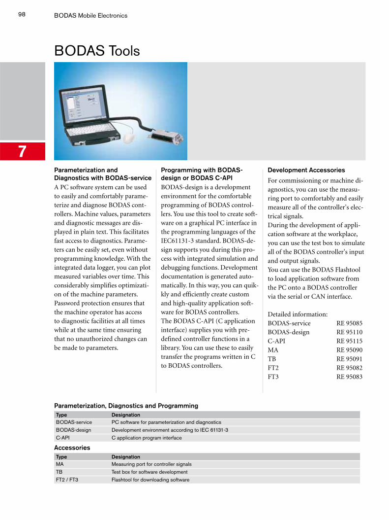
98 BODAS Mobile Electronics
BODAS Tools
7Parameterization and Diagnostics with BODAS-service A PC software system can be used to easily and comfortably parame-terize and diagnose BODAS cont-rollers. Machine values, parameters and diagnostic messages are dis-played in plain text. This facilitates fast access to diagnostics. Parame-ters can be easily set, even without programming knowledge. With the integrated data logger, you can plot measured variables over time. This considerably simplifies optimizati-on of the machine parameters. Password protection ensures that the machine operator has access to diagnostic facilities at all times while at the same time ensuring that no unauthorized changes can be made to parameters.
Programming with BODAS-design or BODAS C-API BODAS-design is a development environment for the comfortable programming of BODAS control-lers. You use this tool to create soft-ware on a graphical PC interface in the programming languages of the IEC61131-3 standard. BODAS-de-sign supports you during this pro-cess with integrated simulation and debugging functions. Development documentation is generated auto-matically. In this way, you can quik-kly and efficiently create custom and high-quality application soft-ware for BODAS controllers. The BODAS C-API (C application interface) supplies you with pre-defined controller functions in a library. You can use these to easily transfer the programs written in C to BODAS controllers.
Development Accessories
For commissioning or machine di-agnostics, you can use the measu-ring port to comfortably and easily measure all of the controller's elec-trical signals.During the development of appli-cation software at the workplace, you can use the test box to simulate all of the BODAS controller's input and output signals. You can use the BODAS Flashtool to load application software from the PC onto a BODAS controller via the serial or CAN interface.
Detailed information:BODAS-service RE 95085BODAS-design RE 95110C-API RE 95115MA RE 95090TB RE 95091FT2 RE 95082FT3 RE 95083
Parameterization, Diagnostics and ProgrammingType DesignationBODAS-service PC software for parameterization and diagnosticsBODAS-design Development environment according to IEC 61131-3C-API C application program interface
AccessoriesType DesignationMA Measuring port for controller signalsTB Test box for software developmentFT2 / FT3 Flashtool for downloading software
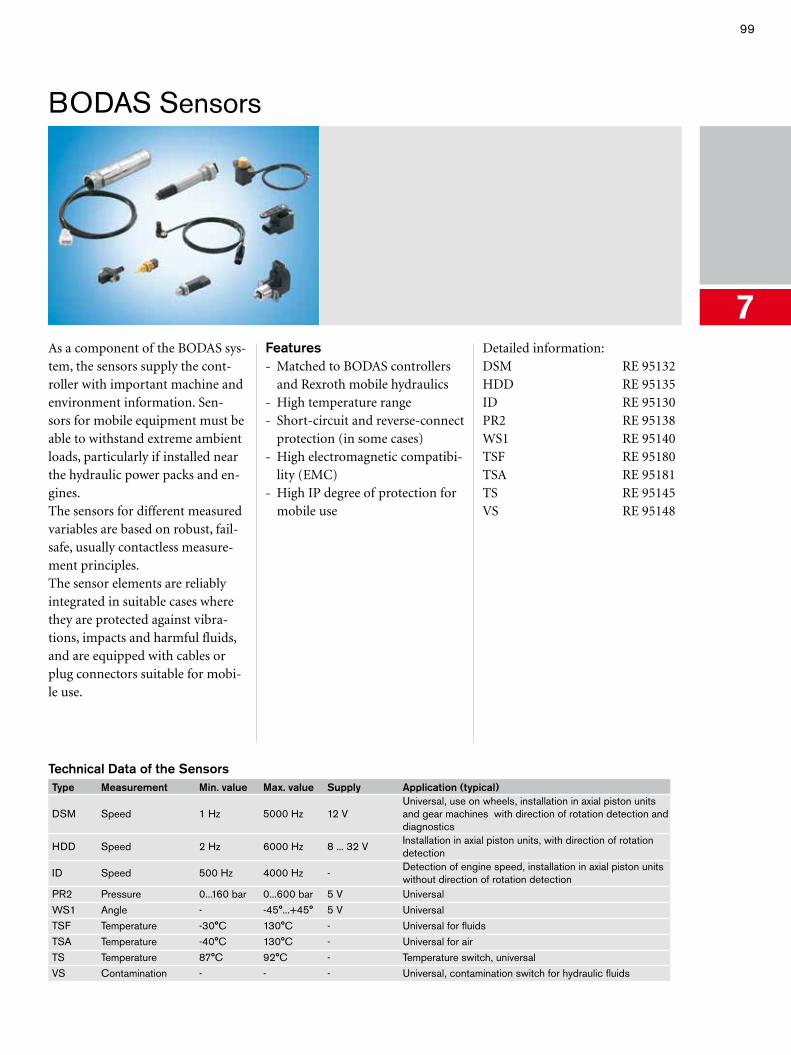
99
BODAS Sensors
7As a component of the BODAS sys-tem, the sensors supply the cont-roller with important machine and environment information. Sen-sors for mobile equipment must be able to withstand extreme ambient loads, particularly if installed near the hydraulic power packs and en-gines.The sensors for different measured variables are based on robust, fail-safe, usually contactless measure-ment principles.The sensor elements are reliably integrated in suitable cases where they are protected against vibra-tions, impacts and harmful fluids, and are equipped with cables or plug connectors suitable for mobi-le use.
Features- Matched to BODAS controllers
and Rexroth mobile hydraulics- High temperature range- Short-circuit and reverse-connect
protection (in some cases)- High electromagnetic compatibi-
lity (EMC)- High IP degree of protection for
mobile use
Detailed information:DSM RE 95132HDD RE 95135ID RE 95130PR2 RE 95138WS1 RE 95140TSF RE 95180TSA RE 95181TS RE 95145VS RE 95148
Technical Data of the SensorsType Measurement Min. value Max. value Supply Application (typical)
DSM Speed 1 Hz 5000 Hz 12 VUniversal, use on wheels, installation in axial piston units and gear machines with direction of rotation detection and diagnostics
HDD Speed 2 Hz 6000 Hz 8 ... 32 VInstallation in axial piston units, with direction of rotation detection
ID Speed 500 Hz 4000 Hz -Detection of engine speed, installation in axial piston units without direction of rotation detection
PR2 Pressure 0...160 bar 0...600 bar 5 V UniversalWS1 Angle - -45°...+45° 5 V UniversalTSF Temperature -30°C 130°C - Universal for fluidsTSA Temperature -40°C 130°C - Universal for airTS Temperature 87°C 92°C - Temperature switch, universalVS Contamination - - - Universal, contamination switch for hydraulic fluids
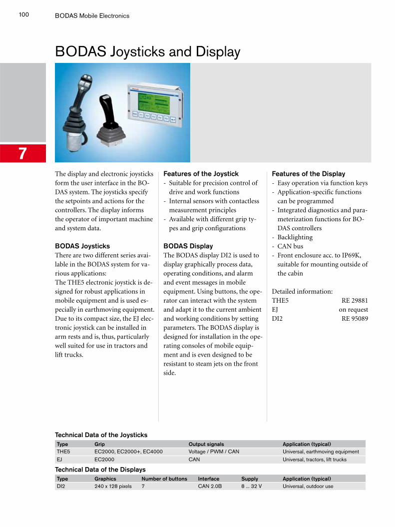
100 BODAS Mobile Electronics
BODAS Joysticks and Display
7The display and electronic joysticks form the user interface in the BO-DAS system. The joysticks specify the setpoints and actions for the controllers. The display informs the operator of important machine and system data.
BODAS Joysticks There are two different series avai-lable in the BODAS system for va-rious applications: The THE5 electronic joystick is de-signed for robust applications in mobile equipment and is used es-pecially in earthmoving equipment.Due to its compact size, the EJ elec-tronic joystick can be installed in arm rests and is, thus, particularly well suited for use in tractors and lift trucks.
Features of the Joystick- Suitable for precision control of
drive and work functions- Internal sensors with contactless
measurement principles- Available with different grip ty-
pes and grip configurations
BODAS DisplayThe BODAS display DI2 is used to display graphically process data, operating conditions, and alarm and event messages in mobile equipment. Using buttons, the ope-rator can interact with the system and adapt it to the current ambient and working conditions by setting parameters. The BODAS display is designed for installation in the ope-rating consoles of mobile equip-ment and is even designed to be resistant to steam jets on the front side.
Features of the Display- Easy operation via function keys- Application-specific functions
can be programmed- Integrated diagnostics and para-
meterization functions for BO-DAS controllers
- Backlighting- CAN bus- Front enclosure acc. to IP69K,
suitable for mounting outside of the cabin
Detailed information:THE5 RE 29881EJ on requestDI2 RE 95089
Technical Data of the JoysticksType Grip Output signals Application (typical)THE5 EC2000, EC2000+, EC4000 Voltage / PWM / CAN Universal, earthmoving equipmentEJ EC2000 CAN Universal, tractors, lift trucks
Technical Data of the DisplaysType Graphics Number of buttons Interface Supply Application (typical)DI2 240 x 128 pixels 7 CAN 2.0B 8 ... 32 V Universal, outdoor use
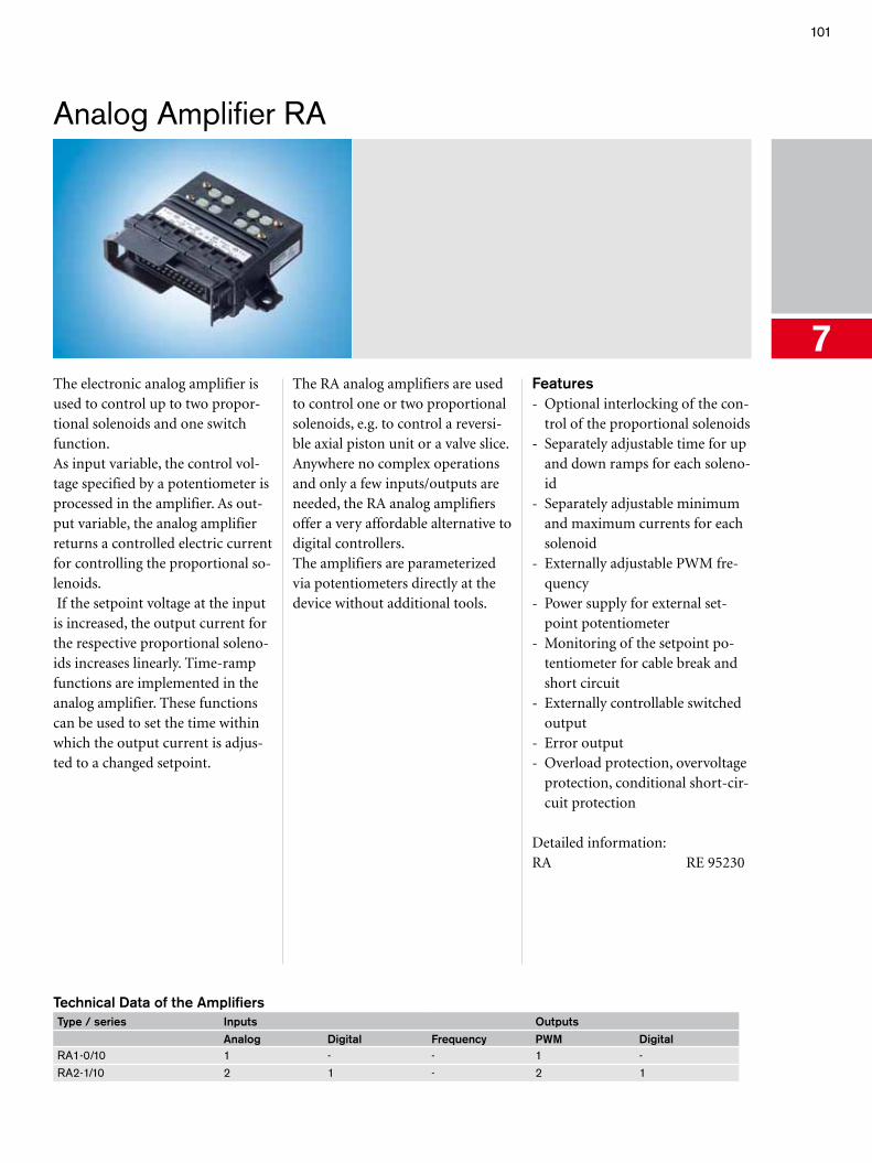
101
Analog Amplifier RA
7The electronic analog amplifier is used to control up to two propor-tional solenoids and one switch function. As input variable, the control vol-tage specified by a potentiometer is processed in the amplifier. As out-put variable, the analog amplifier returns a controlled electric current for controlling the proportional so-lenoids. If the setpoint voltage at the input is increased, the output current for the respective proportional soleno-ids increases linearly. Time-ramp functions are implemented in the analog amplifier. These functions can be used to set the time within which the output current is adjus-ted to a changed setpoint.
The RA analog amplifiers are used to control one or two proportional solenoids, e.g. to control a reversi-ble axial piston unit or a valve slice.Anywhere no complex operations and only a few inputs/outputs are needed, the RA analog amplifiers offer a very affordable alternative to digital controllers. The amplifiers are parameterized via potentiometers directly at the device without additional tools.
Features- Optional interlocking of the con-
trol of the proportional solenoids - Separately adjustable time for up
and down ramps for each soleno-id
- Separately adjustable minimum and maximum currents for each solenoid
- Externally adjustable PWM fre-quency
- Power supply for external set-point potentiometer
- Monitoring of the setpoint po-tentiometer for cable break and short circuit
- Externally controllable switched output
- Error output- Overload protection, overvoltage
protection, conditional short-cir-cuit protection
Detailed information:RA RE 95230
Technical Data of the AmplifiersType / series Inputs Outputs
Analog Digital Frequency PWM DigitalRA1-0/10 1 - - 1 -RA2-1/10 2 1 - 2 1
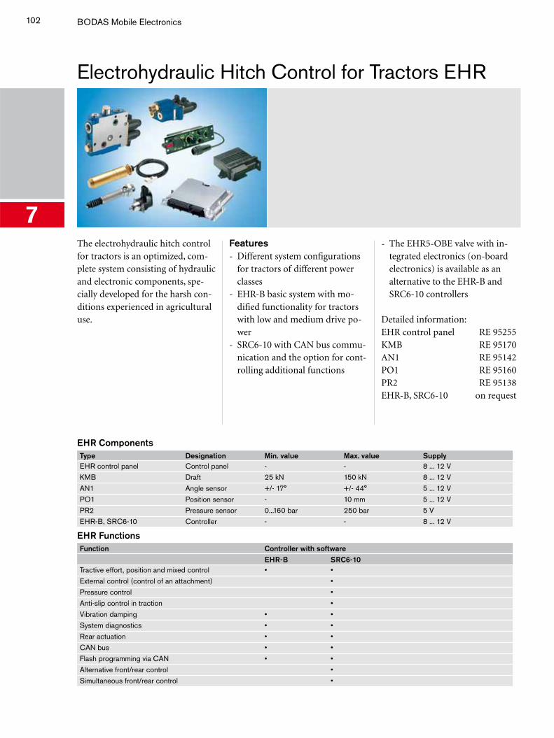
102 BODAS Mobile Electronics
Electrohydraulic Hitch Control for Tractors EHR
7The electrohydraulic hitch control for tractors is an optimized, com-plete system consisting of hydraulic and electronic components, spe-cially developed for the harsh con-ditions experienced in agricultural use.
Features - Different system configurations
for tractors of different power classes
- EHR-B basic system with mo-dified functionality for tractors with low and medium drive po-wer
- SRC6-10 with CAN bus commu-nication and the option for cont-rolling additional functions
- The EHR5-OBE valve with in-tegrated electronics (on-board electronics) is available as an alternative to the EHR-B and SRC6-10 controllers
Detailed information:EHR control panel RE 95255KMB RE 95170AN1 RE 95142PO1 RE 95160PR2 RE 95138EHR-B, SRC6-10 on request
EHR ComponentsType Designation Min. value Max. value SupplyEHR control panel Control panel - - 8 ... 12 VKMB Draft 25 kN 150 kN 8 ... 12 VAN1 Angle sensor +/- 17° +/- 44° 5 ... 12 VPO1 Position sensor - 10 mm 5 ... 12 VPR2 Pressure sensor 0...160 bar 250 bar 5 VEHR-B, SRC6-10 Controller - - 8 ... 12 V
EHR FunctionsFunction Controller with software EHR-B SRC6-10Tractive effort, position and mixed control • •External control (control of an attachment) •Pressure control •Anti-slip control in traction •Vibration damping • •System diagnostics • •Rear actuation • •CAN bus • •Flash programming via CAN • •Alternative front/rear control •Simultaneous front/rear control •
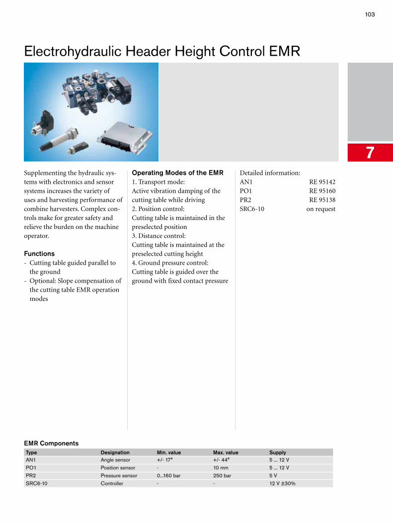
103
Electrohydraulic Header Height Control EMR
7Supplementing the hydraulic sys-tems with electronics and sensor systems increases the variety of uses and harvesting performance of combine harvesters. Complex con-trols make for greater safety and relieve the burden on the machine operator.
Functions - Cutting table guided parallel to
the ground- Optional: Slope compensation of
the cutting table EMR operation modes
Operating Modes of the EMR 1. Transport mode:Active vibration damping of the cutting table while driving 2. Position control:Cutting table is maintained in the preselected position 3. Distance control:Cutting table is maintained at the preselected cutting height 4. Ground pressure control:Cutting table is guided over the ground with fixed contact pressure
Detailed information:AN1 RE 95142PO1 RE 95160PR2 RE 95138SRC6-10 on request
EMR ComponentsType Designation Min. value Max. value SupplyAN1 Angle sensor +/- 17° +/- 44° 5 ... 12 VPO1 Position sensor - 10 mm 5 ... 12 VPR2 Pressure sensor 0...160 bar 250 bar 5 VSRC6-10 Controller - - 12 V ±30%
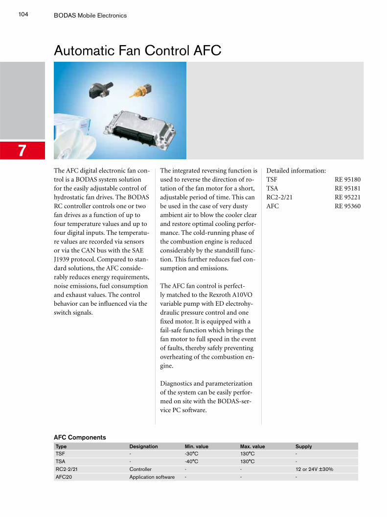
104 BODAS Mobile Electronics
Automatic Fan Control AFC
7The AFC digital electronic fan con-trol is a BODAS system solution for the easily adjustable control of hydrostatic fan drives. The BODAS RC controller controls one or two fan drives as a function of up to four temperature values and up to four digital inputs. The temperatu-re values are recorded via sensors or via the CAN bus with the SAE J1939 protocol. Compared to stan-dard solutions, the AFC conside-rably reduces energy requirements, noise emissions, fuel consumption and exhaust values. The control behavior can be influenced via the switch signals.
The integrated reversing function is used to reverse the direction of ro-tation of the fan motor for a short, adjustable period of time. This can be used in the case of very dusty ambient air to blow the cooler clear and restore optimal cooling perfor-mance. The cold-running phase of the combustion engine is reduced considerably by the standstill func-tion. This further reduces fuel con-sumption and emissions.
The AFC fan control is perfect-ly matched to the Rexroth A10VO variable pump with ED electrohy-draulic pressure control and one fixed motor. It is equipped with a fail-safe function which brings the fan motor to full speed in the event of faults, thereby safely preventing overheating of the combustion en-gine.
Diagnostics and parameterization of the system can be easily perfor-med on site with the BODAS-ser-vice PC software.
Detailed information:TSF RE 95180TSA RE 95181RC2-2/21 RE 95221AFC RE 95360
AFC ComponentsType Designation Min. value Max. value SupplyTSF - -30°C 130°C -TSA - -40°C 130°C -RC2-2/21 Controller - - 12 or 24V ±30%AFC20 Application software - - -
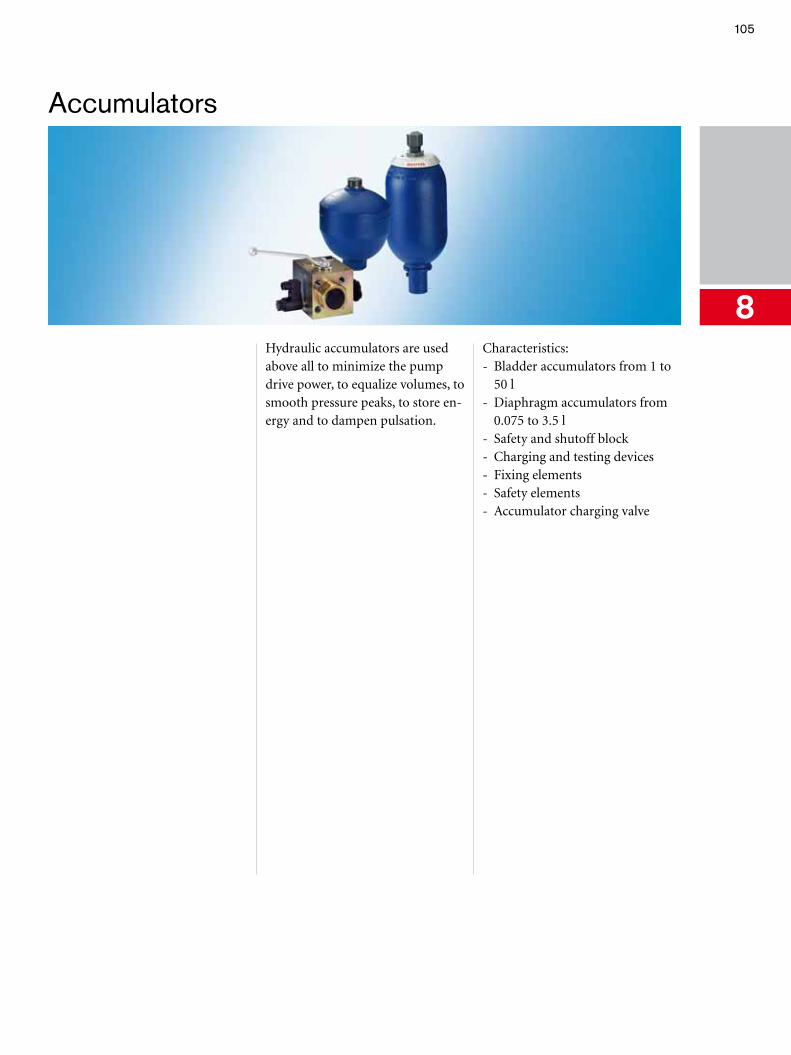
105
Accumulators
8Hydraulic accumulators are used above all to minimize the pump drive power, to equalize volumes, to smooth pressure peaks, to store en-ergy and to dampen pulsation.
Characteristics:- Bladder accumulators from 1 to
50 l- Diaphragm accumulators from
0.075 to 3.5 l- Safety and shutoff block- Charging and testing devices- Fixing elements- Safety elements- Accumulator charging valve
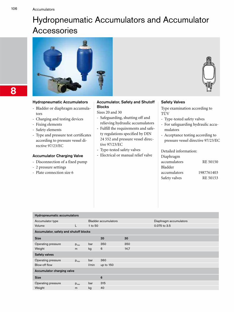
106 Accumulators
Hydropneumatic Accumulators and Accumulator Accessories
8Hydropneumatic Accumulators
- Bladder or diaphragm accumula-tors
- Charging and testing devices- Fixing elements- Safety elements- Type and pressure test certificates
according to pressure vessel di-rective 97/23/EC
Accumulator Charging Valve
- Disconnection of a fixed pump- 2 pressure settings- Plate connection size 6
Accumulator, Safety and Shutoff Blocks Sizes 20 and 30- Safeguarding, shutting off and
relieving hydraulic accumulators- Fulfill the requirements and safe-
ty regulations specified by DIN 24 552 and pressure vessel direc-tive 97/23/EC
- Type-tested safety valves- Electrical or manual relief valve
Safety Valves
Type examination according to TÜV- Type-tested safety valves- For safeguarding hydraulic accu-
mulators- Acceptance testing according to
pressure vessel directive 97/23/EC
Detailed information:Diaphragm accumulators RE 50150Bladder accumulators 1987761403Safety valves RE 50153
Hydropneumatic accumulators
Accumulator type Bladder accumulators Diaphragm accumulatorsVolume L 1 to 50 0.075 to 3.5
Accumulator, safety and shutoff blocks
Size 20 30
Operating pressure pmax bar 350 350Weight m kg 6 14,7
Safety valves
Operating pressure pmax bar 360Blow-off flow l/min up to 150
Accumulator charging valve
Size 6
Operating pressure pmax bar 315Weight m kg 40


Bosch Rexroth AGHydraulicsGlockeraustraße 489275 Elchingen, GermanyTel. +49 7308 82-0Fax +49 7308 [email protected]/brm
Printed in GermanyRE 90112/12.06