Program 60-104—External Gear Contact and Backlash Introduction · 60-104—External Gear Contact...
48
Program 60-104—External Gear Contact and Backlash 1 Introduction This is a model of the contact conditions between two external spur or helical involute gears. The contact ratios, start of active profile, specific sliding and many other geometrical conditions are calculated and checked. In addition, the tooth thickness, center distance and backlash are calculated. The tooth thickness of gears is specified at the reference pitch diameter which is the diameter obtained by dividing the number of teeth by the transverse pitch (diametral pitch in the plane of rotation). The reference pitch diameters will be the same as the operating pitch diameters only if the gears are meshed at “standard” center distance. The “standard” center distance is one half the sum of the reference pitch diameters. The transverse backlash at the “standard” center distance will be the reference transverse circular pitch less the tooth thickness of both gears and would be a circular arc measurement along the reference pitch diameter. The operating pressure angle will be equal to the “nominal” pressure angle. When the gears are meshed on any other center distance the operating pitch diameters will not be the reference pitch diameters. The operating pressure angle will not be the “nominal” pressure angle. The transverse backlash will then be the operating circular pitch less the tooth thickness at the operating pitch diameters of both gears and would be a circular arc measurement along the operating pitch diameter. The change in reference pitch diameter tooth thickness calculated in the usual manner for high or low addendum gears operating on “non-standard” centers uses the “nominal” pressure angle of the gear as an approximation. Since the operating pressure angle changes with the center distance this introduces an error in the backlash calculated for these gear sets. If the center distance change from “standard” is extensive the error can be quite large. (The operating backlash will be larger than anticipated whether the center distance is larger or smaller than “standard”.) The model avoids this problem by using the “operating” dimensions of the gear set for these calculations after finding the operating pitch diameters. Caution Conditions The model checks many conditions to be sure that the gear set will function as intended. The gear geometry caution conditions are: 1. All Recess Action–all contact between teeth occurs past the operating pitch point of the set. This is a desirable condition if the sliding velocity is not too high at the end of action and the strength balance between the driver and driven is not compromised
Transcript of Program 60-104—External Gear Contact and Backlash Introduction · 60-104—External Gear Contact...
Program 60-104—External Gear Contact and Backlash
1
Introduction This is a model of the contact conditions between two external spur or helical involute gears. The contact ratios, start of active profile, specific sliding and many other geometrical conditions are calculated and checked. In addition, the tooth thickness, center distance and backlash are calculated. The tooth thickness of gears is specified at the reference pitch diameter which is the diameter obtained by dividing the number of teeth by the transverse pitch (diametral pitch in the plane of rotation). The reference pitch diameters will be the same as the operating pitch diameters only if the gears are meshed at “standard” center distance. The “standard” center distance is one half the sum of the reference pitch diameters. The transverse backlash at the “standard” center distance will be the reference transverse circular pitch less the tooth thickness of both gears and would be a circular arc measurement along the reference pitch diameter. The operating pressure angle will be equal to the “nominal” pressure angle. When the gears are meshed on any other center distance the operating pitch diameters will not be the reference pitch diameters. The operating pressure angle will not be the “nominal” pressure angle. The transverse backlash will then be the operating circular pitch less the tooth thickness at the operating pitch diameters of both gears and would be a circular arc measurement along the operating pitch diameter. The change in reference pitch diameter tooth thickness calculated in the usual manner for high or low addendum gears operating on “non-standard” centers uses the “nominal” pressure angle of the gear as an approximation. Since the operating pressure angle changes with the center distance this introduces an error in the backlash calculated for these gear sets. If the center distance change from “standard” is extensive the error can be quite large. (The operating backlash will be larger than anticipated whether the center distance is larger or smaller than “standard”.) The model avoids this problem by using the “operating” dimensions of the gear set for these calculations after finding the operating pitch diameters. Caution Conditions
The model checks many conditions to be sure that the gear set will function as intended. The gear geometry caution conditions are:
1. All Recess Action–all contact between teeth occurs past the operating pitch point of the set. This is a desirable condition if the sliding velocity is not too high at the end of action and the strength balance between the driver and driven is not compromised
UTS Integrated Gear Software
2
2. Approach Action over 50%–there is more contact before the pitch point than after the pitch point. This should be avoided because the teeth are approaching each other and the effective coefficient of friction may be higher in approach than in recess action for soft gear materials. More high addendum on the driver and/or low addendum on the driven will reduce approach action
3. Total Contact Ratio Less than 1.2–a total contact ratio this low will usually result in a gear set that is noisy and rough running. In spur gears the highest point of single tooth load will be near the tooth tip. Very little room is available for the application of tip relief
4. Check for Undercut in Root–there is a possibility of undercut in the root area of one or both of the gears. Without the cutting tool geometry it is not possible to be sure that undercutting will occur but for “standard” cutting tools it is likely. This condition must be checked further (see UTS Program 500, Models 60-400 and 60-410)
5. Contact Below Base Circle–the tooth tip of one or both of the gears is attempting to contact the mating tooth below the base circle - since there is no involute below the base circle this condition will reduce the profile contact ratio and may cause interference
6. Contact Ratio Less than One–the gear set is not conjugate and is not usable. The loaded tooth pair will drop the load before the next pair is in contact, so the set may jam.
7. Teeth Entered Not Integer–you have entered a non-integer for the number of teeth in one or both of the gears.
8. Negative Backlash will Not Assemble–the total thickness of the gears when assembled at the operating center distance is greater than the operating circular pitch. This will prevent assembly of the gears at the operating center distance.
9. Specific Sliding Over Three–the ratio of sliding to rolling velocity between the contacting flanks is over 3. This condition can cause wear, scoring and noisy operation. High specific sliding is more detrimental at higher pitch line velocities. Specific sliding can usually be reduced by moving contact away from the base circle (center distance greater than “standard”, high addendum, higher operating pressure angle).
10. Top Land Width–(normal tooth thickness at outside diameter) is less than
0.275/Normal Diametral Pitch (or 0.275*Module). The tooth tip is quite
60-104—External Gear Contact And Backlash
3
pointed. If the gear is case hardened the tooth tip may be over hardened and brittle.
11. Trans PA Negative will Not Mesh–the center distance is too small for the base circle diameters of the gears. The base circles are overlapping, and it is not possible for gears to be conjugate under this condition.
Because TK Solver allows partial solutions, you may investigate contact conditions directly in the TK Solver model as you add more and more data. For example, you might proceed this way to obtain a gear ratio: Enter: 22 for DRIVER, number of teeth 2.48 for Gear ratio Solve Output: 54.56 for DRIVEN, number of teeth The number of teeth must be an integer so: Enter: 55 for DRIVEN, number of teeth Blank: Gear ratio Solve Output: 2.5 for Gear ratio You can build a solution in this way as far as you wish. It is best to proceed until the CAUTION MESSAGE is no longer blank.
UTS Integrated Gear Software
4
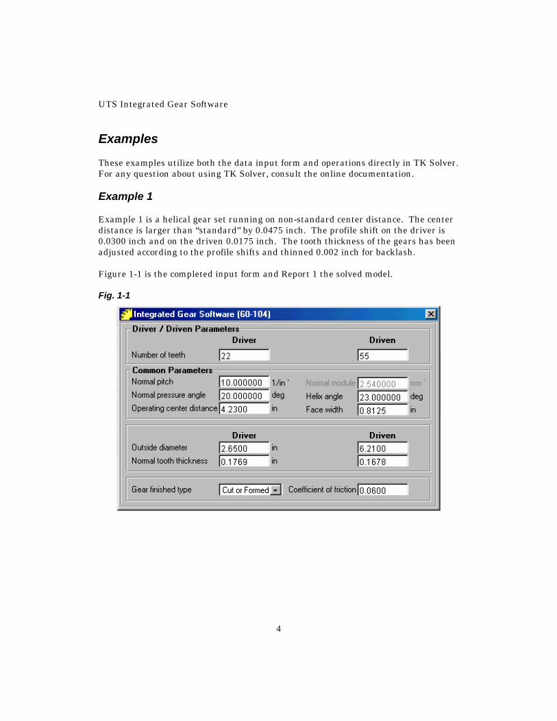
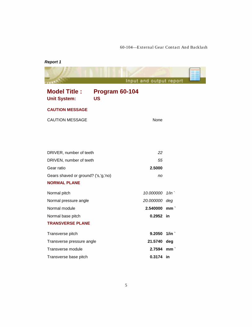
Examples These examples utilize both the data input form and operations directly in TK Solver. For any question about using TK Solver, consult the online documentation. Example 1 Example 1 is a helical gear set running on non-standard center distance. The center distance is larger than “standard” by 0.0475 inch. The profile shift on the driver is 0.0300 inch and on the driven 0.0175 inch. The tooth thickness of the gears has been adjusted according to the profile shifts and thinned 0.002 inch for backlash. Figure 1-1 is the completed input form and Report 1 the solved model. Fig. 1-1
60-104—External Gear Contact And Backlash
5
Report 1
Model Title : Program 60-104 Unit System: US
CAUTION MESSAGE
CAUTION MESSAGE None
DRIVER, number of teeth 22
DRIVEN, number of teeth 55
Gear ratio 2.5000
Gears shaved or ground? ('s,'g,'no) no
NORMAL PLANE
Normal pitch 10.000000 1/in `
Normal pressure angle 20.000000 deg
Normal module 2.540000 mm `
Normal base pitch 0.2952 in
TRANSVERSE PLANE
Transverse pitch 9.2050 1/in `
Transverse pressure angle 21.5740 deg
Transverse module 2.7594 mm `
Transverse base pitch 0.3174 in
UTS Integrated Gear Software
6
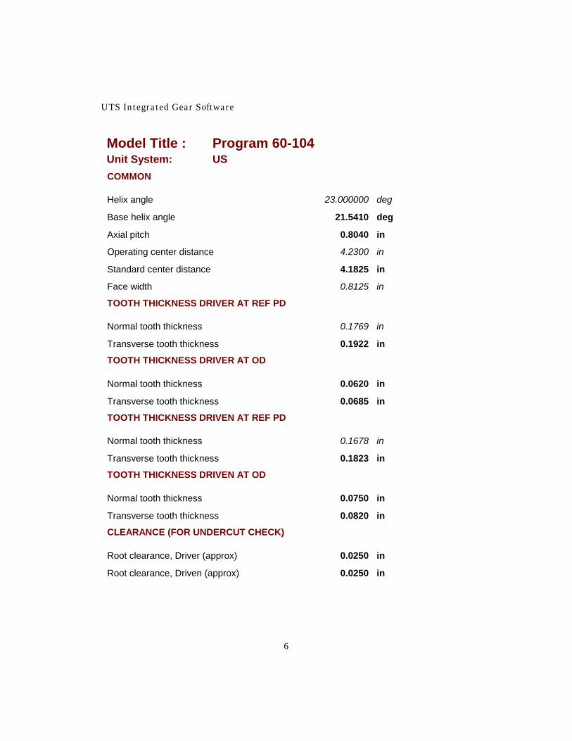
Model Title : Program 60-104 Unit System: US COMMON
Helix angle 23.000000 deg
Base helix angle 21.5410 deg
Axial pitch 0.8040 in
Operating center distance 4.2300 in
Standard center distance 4.1825 in
Face width 0.8125 in
TOOTH THICKNESS DRIVER AT REF PD
Normal tooth thickness 0.1769 in
Transverse tooth thickness 0.1922 in
TOOTH THICKNESS DRIVER AT OD
Normal tooth thickness 0.0620 in
Transverse tooth thickness 0.0685 in
TOOTH THICKNESS DRIVEN AT REF PD
Normal tooth thickness 0.1678 in
Transverse tooth thickness 0.1823 in
TOOTH THICKNESS DRIVEN AT OD
Normal tooth thickness 0.0750 in
Transverse tooth thickness 0.0820 in
CLEARANCE (FOR UNDERCUT CHECK)
Root clearance, Driver (approx) 0.0250 in
Root clearance, Driven (approx) 0.0250 in
60-104—External Gear Contact And Backlash
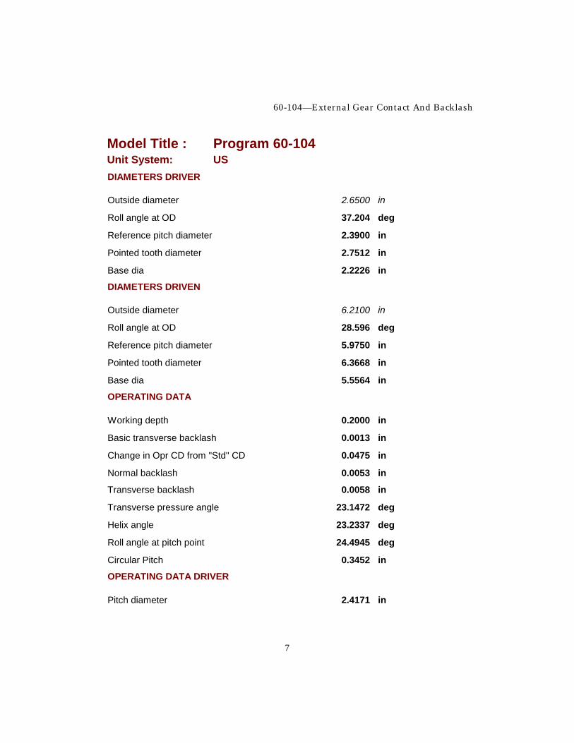
7
Model Title : Program 60-104 Unit System: US DIAMETERS DRIVER
Outside diameter 2.6500 in
Roll angle at OD 37.204 deg
Reference pitch diameter 2.3900 in
Pointed tooth diameter 2.7512 in
Base dia 2.2226 in
DIAMETERS DRIVEN
Outside diameter 6.2100 in
Roll angle at OD 28.596 deg
Reference pitch diameter 5.9750 in
Pointed tooth diameter 6.3668 in
Base dia 5.5564 in
OPERATING DATA
Working depth 0.2000 in
Basic transverse backlash 0.0013 in
Change in Opr CD from "Std" CD 0.0475 in
Normal backlash 0.0053 in
Transverse backlash 0.0058 in
Transverse pressure angle 23.1472 deg
Helix angle 23.2337 deg
Roll angle at pitch point 24.4945 deg
Circular Pitch 0.3452 in
OPERATING DATA DRIVER
Pitch diameter 2.4171 in
UTS Integrated Gear Software
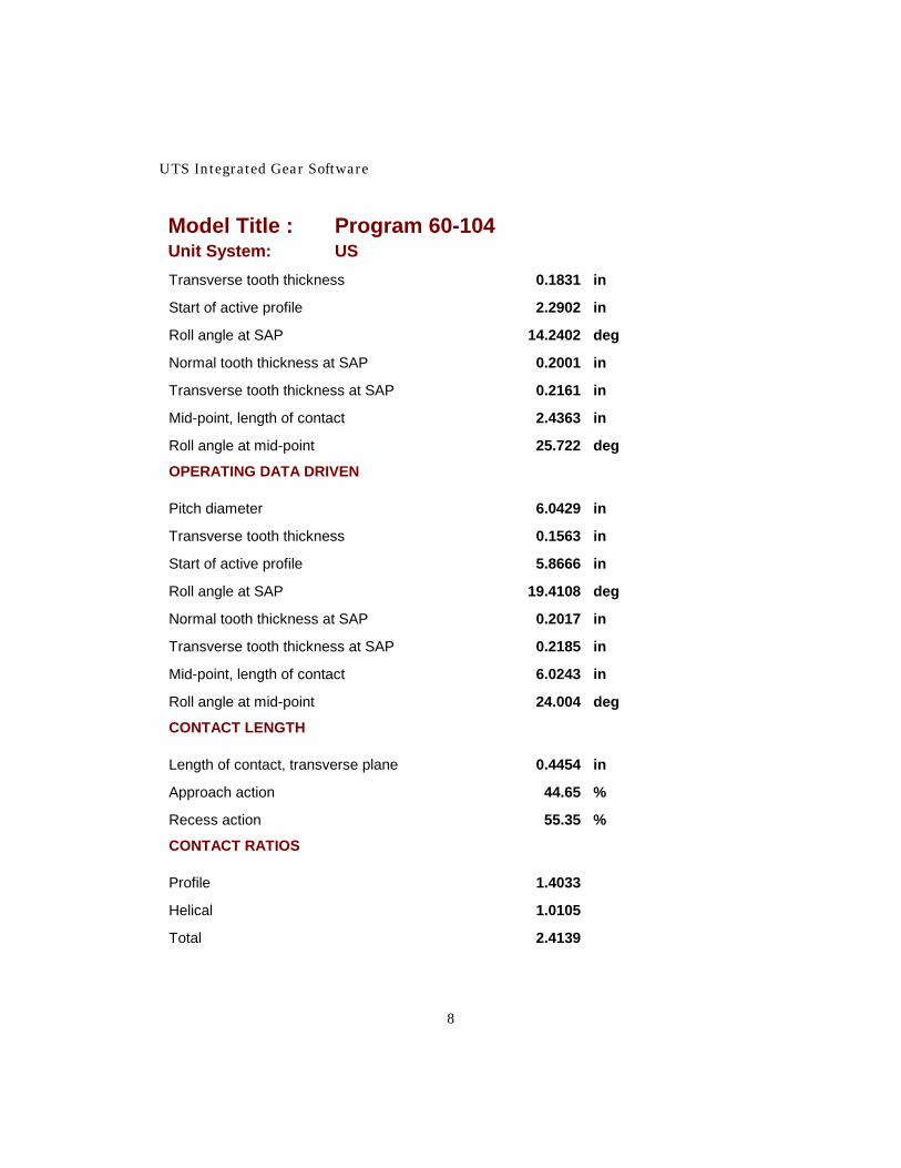
8
Model Title : Program 60-104 Unit System: US Transverse tooth thickness 0.1831 in
Start of active profile 2.2902 in
Roll angle at SAP 14.2402 deg
Normal tooth thickness at SAP 0.2001 in
Transverse tooth thickness at SAP 0.2161 in
Mid-point, length of contact 2.4363 in
Roll angle at mid-point 25.722 deg
OPERATING DATA DRIVEN
Pitch diameter 6.0429 in
Transverse tooth thickness 0.1563 in
Start of active profile 5.8666 in
Roll angle at SAP 19.4108 deg
Normal tooth thickness at SAP 0.2017 in
Transverse tooth thickness at SAP 0.2185 in
Mid-point, length of contact 6.0243 in
Roll angle at mid-point 24.004 deg
CONTACT LENGTH
Length of contact, transverse plane 0.4454 in
Approach action 44.65 %
Recess action 55.35 %
CONTACT RATIOS
Profile 1.4033
Helical 1.0105
Total 2.4139

60-104—External Gear Contact And Backlash
9
Model Title : Program 60-104 Unit System: US LINES OF CONTACT ACROSS TEETH
Max total length 1.2313 in
Min total length 1.2221 in
Ratio: (Max length / Min length) 1.0075
SPECIFIC SLIDING RATIOS
Driver start of active profile 1.008
Driver outside diameter 0.478
Driven start of active profile 0.917
Driven outside diameter 0.502
Coefficient of friction 0.0600
Approx power loss 0.71 %
Approx Efficiency 99.29 %
Iteration trigger variable for solving CD 1.0114 from tooth thickness and backlash
I factor for contact stress 0.2035 Note that with a coefficient of friction of .06, the efficiency is about 99.29%. The efficiency is calculated in accordance with the methods in Chapter 12 of Dudley's Gear Handbook, 2nd Edition, by E.E. Shipley, published by McGraw-Hill. To illustrate the ease of modifying a gear set we will take the existing solution and modify it to obtain a full recess action gear set. Since the outside diameters must be modified, the first step is to change the OD of the driven gear. The OD of the driven gear must be equal to the operating pitch diameter to insure that all tooth action must take place past the pitch point.
UTS Integrated Gear Software
10
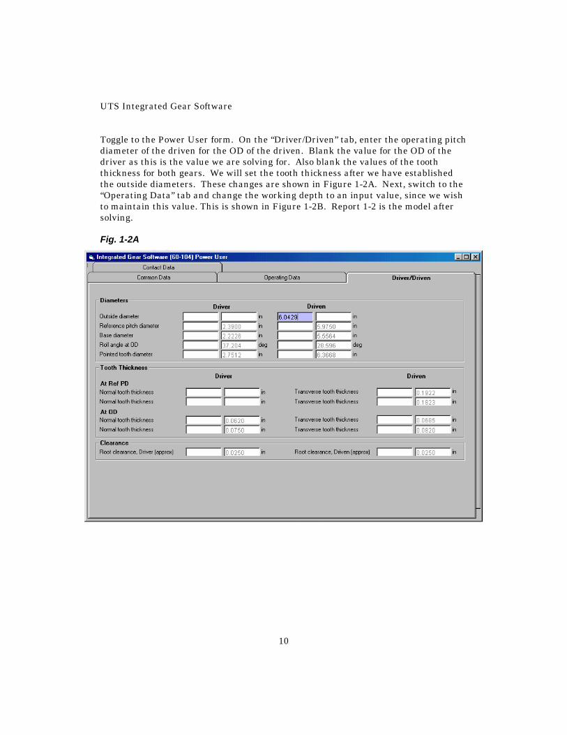
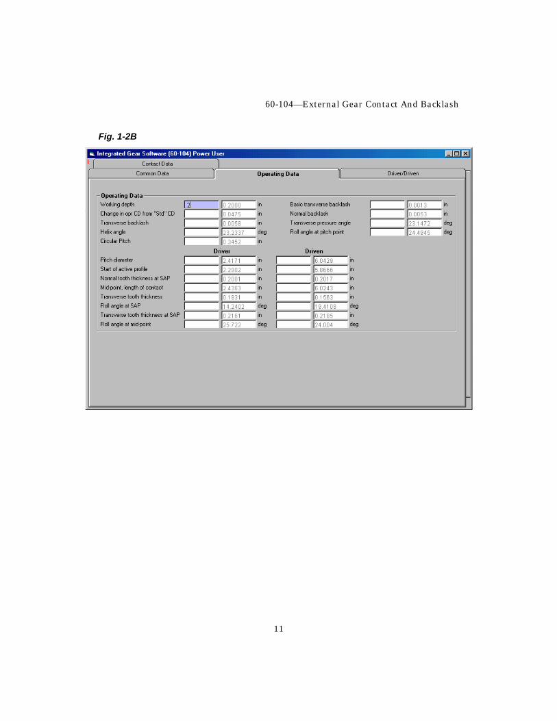
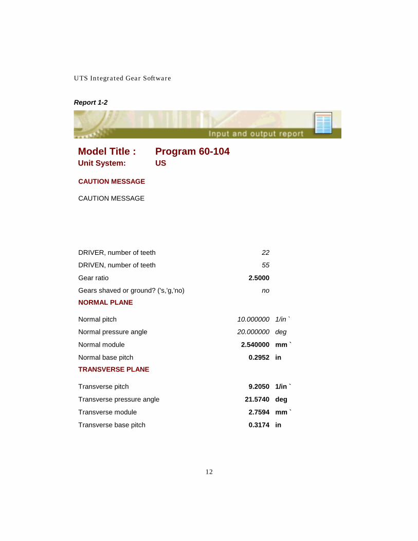
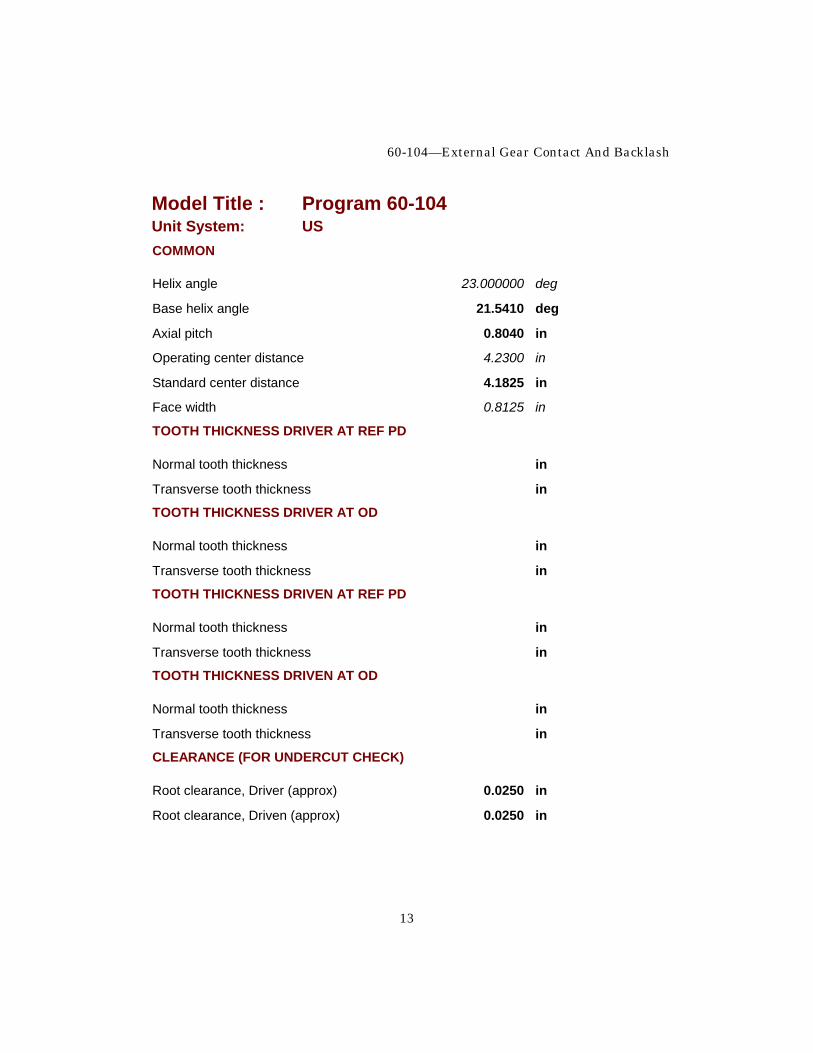
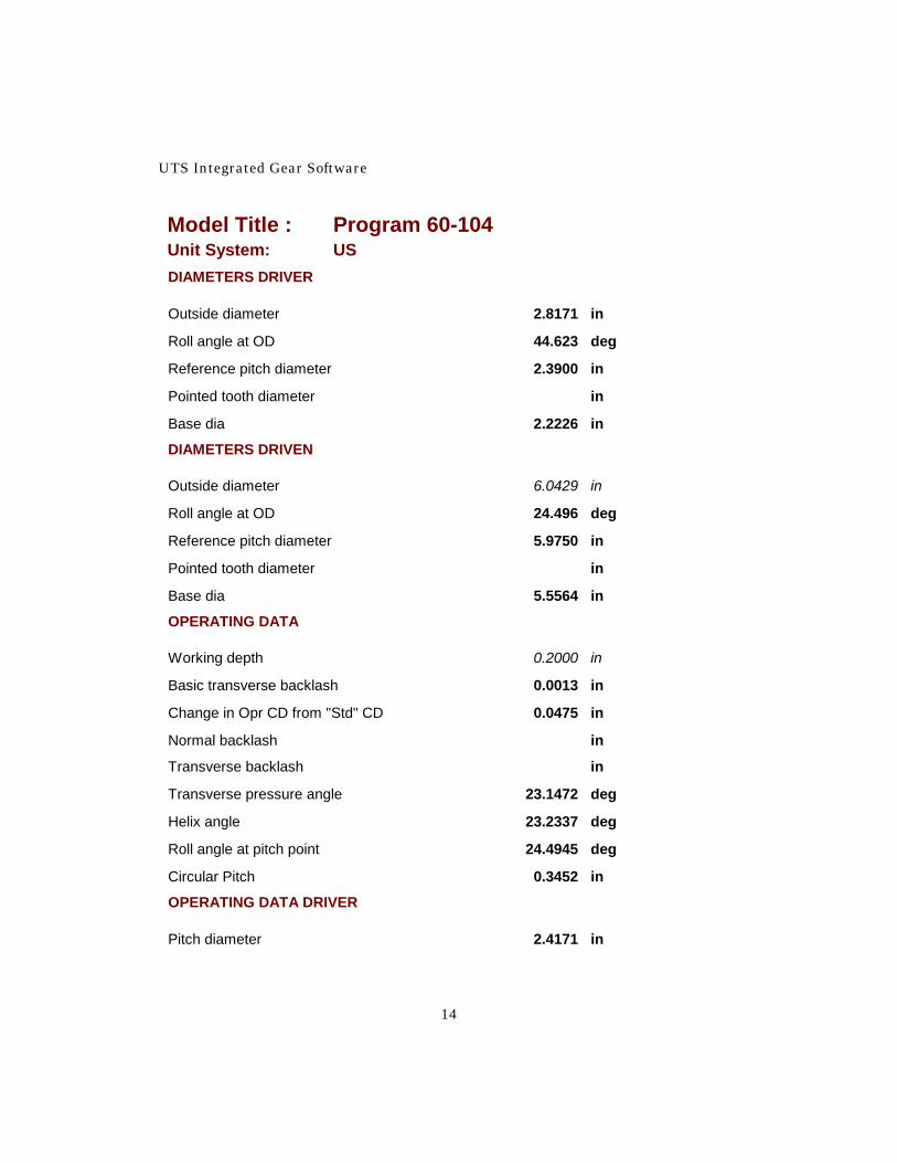
Toggle to the Power User form. On the “Driver/Driven” tab, enter the operating pitch diameter of the driven for the OD of the driven. Blank the value for the OD of the driver as this is the value we are solving for. Also blank the values of the tooth thickness for both gears. We will set the tooth thickness after we have established the outside diameters. These changes are shown in Figure 1-2A. Next, switch to the “Operating Data” tab and change the working depth to an input value, since we wish to maintain this value. This is shown in Figure 1-2B. Report 1-2 is the model after solving. Fig. 1-2A
60-104—External Gear Contact And Backlash
11
Fig. 1-2B
UTS Integrated Gear Software
12
Report 1-2
Model Title : Program 60-104 Unit System: US
CAUTION MESSAGE
CAUTION MESSAGE
DRIVER, number of teeth 22
DRIVEN, number of teeth 55
Gear ratio 2.5000
Gears shaved or ground? ('s,'g,'no) no
NORMAL PLANE
Normal pitch 10.000000 1/in `
Normal pressure angle 20.000000 deg
Normal module 2.540000 mm `
Normal base pitch 0.2952 in
TRANSVERSE PLANE
Transverse pitch 9.2050 1/in `
Transverse pressure angle 21.5740 deg
Transverse module 2.7594 mm `
Transverse base pitch 0.3174 in
60-104—External Gear Contact And Backlash
13
Model Title : Program 60-104 Unit System: US COMMON
Helix angle 23.000000 deg
Base helix angle 21.5410 deg
Axial pitch 0.8040 in
Operating center distance 4.2300 in
Standard center distance 4.1825 in
Face width 0.8125 in
TOOTH THICKNESS DRIVER AT REF PD
Normal tooth thickness in
Transverse tooth thickness in
TOOTH THICKNESS DRIVER AT OD
Normal tooth thickness in
Transverse tooth thickness in
TOOTH THICKNESS DRIVEN AT REF PD
Normal tooth thickness in
Transverse tooth thickness in
TOOTH THICKNESS DRIVEN AT OD
Normal tooth thickness in
Transverse tooth thickness in
CLEARANCE (FOR UNDERCUT CHECK)
Root clearance, Driver (approx) 0.0250 in
Root clearance, Driven (approx) 0.0250 in
UTS Integrated Gear Software
14
Model Title : Program 60-104 Unit System: US DIAMETERS DRIVER
Outside diameter 2.8171 in
Roll angle at OD 44.623 deg
Reference pitch diameter 2.3900 in
Pointed tooth diameter in
Base dia 2.2226 in
DIAMETERS DRIVEN
Outside diameter 6.0429 in
Roll angle at OD 24.496 deg
Reference pitch diameter 5.9750 in
Pointed tooth diameter in
Base dia 5.5564 in
OPERATING DATA
Working depth 0.2000 in
Basic transverse backlash 0.0013 in
Change in Opr CD from "Std" CD 0.0475 in
Normal backlash in
Transverse backlash in
Transverse pressure angle 23.1472 deg
Helix angle 23.2337 deg
Roll angle at pitch point 24.4945 deg
Circular Pitch 0.3452 in
OPERATING DATA DRIVER
Pitch diameter 2.4171 in

60-104—External Gear Contact And Backlash
15
Model Title : Program 60-104 Unit System: US Transverse tooth thickness in
Start of active profile 2.4171 in
Roll angle at SAP 24.4917 deg
Normal tooth thickness at SAP in
Transverse tooth thickness at SAP in
Mid-point, length of contact 2.5955 in
Roll angle at mid-point 34.557 deg
OPERATING DATA DRIVEN
Pitch diameter 6.0429 in
Transverse tooth thickness in
Start of active profile 5.7807 in
Roll angle at SAP 16.4430 deg
Normal tooth thickness at SAP in
Transverse tooth thickness at SAP in
Mid-point, length of contact 5.9003 in
Roll angle at mid-point 20.469 deg
CONTACT LENGTH
Length of contact, transverse plane 0.3905 in
Approach action 0.01 %
Recess action 99.99 %
CONTACT RATIOS
Profile 1.2303
Helical 1.0105
Total 2.2408
UTS Integrated Gear Software
16
Model Title : Program 60-104 Unit System: US LINES OF CONTACT ACROSS TEETH
Max total length 1.0817 in
Min total length 1.0725 in
Ratio: (Max length / Min length) 1.0085
SPECIFIC SLIDING RATIOS
Driver start of active profile 0.000
Driver outside diameter 0.632
Driven start of active profile 1.714
Driven outside diameter 0.000
Coefficient of friction 0.0600
Approx power loss 1.23 %
Approx Efficiency 98.77 %
Iteration trigger variable for solving CD 1.0114 from tooth thickness and backlash
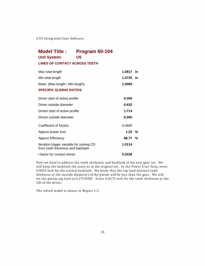
I factor for contact stress 0.2028 Now we need to address the tooth thickness and backlash of the new gear set. We will keep the backlash the same as in the original set. In the Power User form, enter 0.0053 inch for the normal backlash. We know that the top land (normal tooth thickness at the outside diameter) of the pinion will be less than the gear. We will set the pinion top land to 0.275/NDP. Enter 0.0275 inch for the tooth thickness at the OD of the driver. The solved model is shown in Report 1-3.

60-104—External Gear Contact And Backlash
17
Report 1-3
Model Title : Program 60-104 Unit System: US
CAUTION MESSAGE
CAUTION MESSAGE None
DRIVER, number of teeth 22
DRIVEN, number of teeth 55
Gear ratio 2.5000
Gears shaved or ground? ('s,'g,'no) no
NORMAL PLANE
Normal pitch 10.000000 1/in `
Normal pressure angle 20.000000 deg
Normal module 2.540000 mm `
Normal base pitch 0.2952 in
TRANSVERSE PLANE
Transverse pitch 9.2050 1/in `
Transverse pressure angle 21.5740 deg
Transverse module 2.7594 mm `
Transverse base pitch 0.3174 in

UTS Integrated Gear Software
18
Model Title : Program 60-104 Unit System: US COMMON
Helix angle 23.000000 deg
Base helix angle 21.5410 deg
Axial pitch 0.8040 in
Operating center distance 4.2300 in
Standard center distance 4.1825 in
Face width 0.8125 in
TOOTH THICKNESS DRIVER AT REF PD
Normal tooth thickness 0.2402 in
Transverse tooth thickness 0.2609 in
TOOTH THICKNESS DRIVER AT OD
Normal tooth thickness 0.0275 in
Transverse tooth thickness 0.0308 in
TOOTH THICKNESS DRIVEN AT REF PD
Normal tooth thickness 0.1045 in
Transverse tooth thickness 0.1135 in
TOOTH THICKNESS DRIVEN AT OD
Normal tooth thickness 0.0797 in
Transverse tooth thickness 0.0867 in
CLEARANCE (FOR UNDERCUT CHECK)
Root clearance, Driver (approx) 0.0250 in
Root clearance, Driven (approx) 0.0250 in

60-104—External Gear Contact And Backlash
19
Model Title : Program 60-104 Unit System: US DIAMETERS DRIVER
Outside diameter 2.8171 in
Roll angle at OD 44.623 deg
Reference pitch diameter 2.3900 in
Pointed tooth diameter 2.8561 in
Base dia 2.2226 in
DIAMETERS DRIVEN
Outside diameter 6.0429 in
Roll angle at OD 24.496 deg
Reference pitch diameter 5.9750 in
Pointed tooth diameter 6.2310 in
Base dia 5.5564 in
OPERATING DATA
Working depth 0.2000 in
Basic transverse backlash 0.0013 in
Change in Opr CD from "Std" CD 0.0475 in
Normal backlash 0.0053 in
Transverse backlash 0.0058 in
Transverse pressure angle 23.1472 deg
Helix angle 23.2337 deg
Roll angle at pitch point 24.4945 deg
Circular Pitch 0.3452 in
OPERATING DATA DRIVER
Pitch diameter 2.4171 in

UTS Integrated Gear Software
20
Model Title : Program 60-104 Unit System: US Transverse tooth thickness 0.2527 in
Start of active profile 2.4171 in
Roll angle at SAP 24.4917 deg
Normal tooth thickness at SAP 0.2322 in
Transverse tooth thickness at SAP 0.2527 in
Mid-point, length of contact 2.5955 in
Roll angle at mid-point 34.557 deg
OPERATING DATA DRIVEN
Pitch diameter 6.0429 in
Transverse tooth thickness 0.0867 in
Start of active profile 5.7807 in
Roll angle at SAP 16.4430 deg
Normal tooth thickness at SAP 0.1623 in
Transverse tooth thickness at SAP 0.1755 in
Mid-point, length of contact 5.9003 in
Roll angle at mid-point 20.469 deg
CONTACT LENGTH
Length of contact, transverse plane 0.3905 in
Approach action 0.01 %
Recess action 99.99 %
CONTACT RATIOS
Profile 1.2303
Helical 1.0105
Total 2.2408
60-104—External Gear Contact And Backlash
21
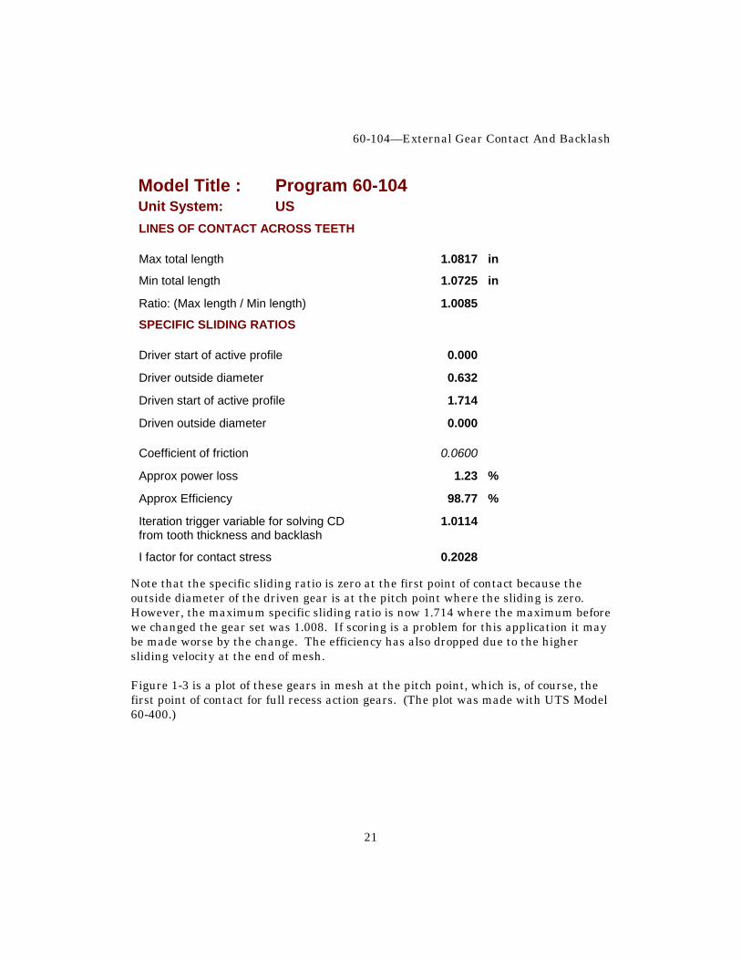
Model Title : Program 60-104 Unit System: US LINES OF CONTACT ACROSS TEETH
Max total length 1.0817 in
Min total length 1.0725 in
Ratio: (Max length / Min length) 1.0085
SPECIFIC SLIDING RATIOS
Driver start of active profile 0.000
Driver outside diameter 0.632
Driven start of active profile 1.714
Driven outside diameter 0.000
Coefficient of friction 0.0600
Approx power loss 1.23 %
Approx Efficiency 98.77 %
Iteration trigger variable for solving CD 1.0114 from tooth thickness and backlash
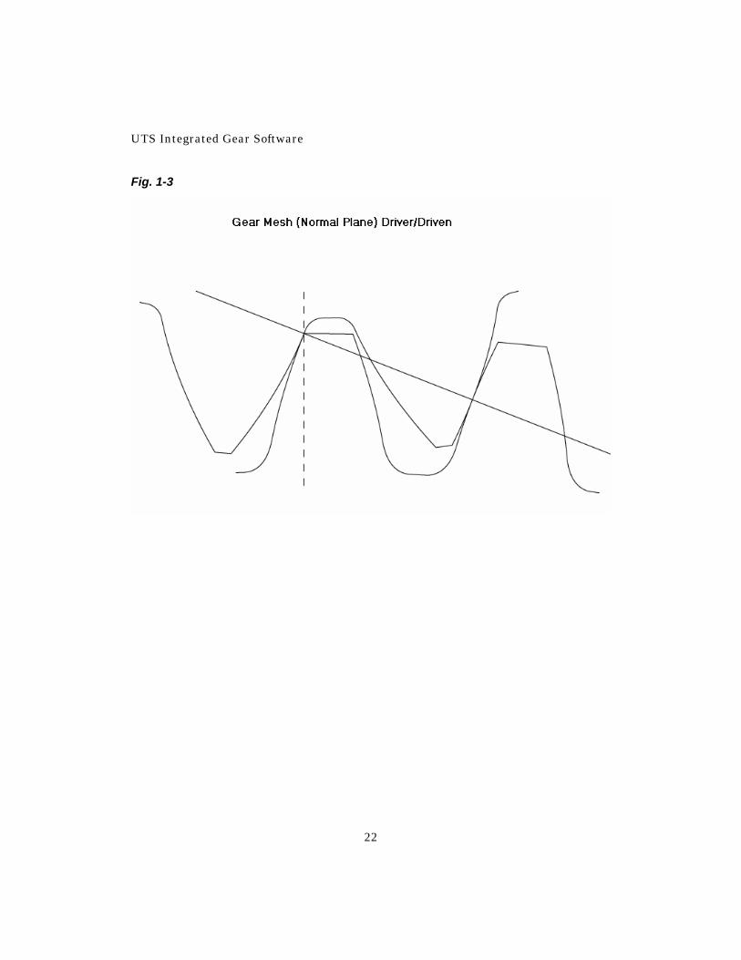
I factor for contact stress 0.2028 Note that the specific sliding ratio is zero at the first point of contact because the outside diameter of the driven gear is at the pitch point where the sliding is zero. However, the maximum specific sliding ratio is now 1.714 where the maximum before we changed the gear set was 1.008. If scoring is a problem for this application it may be made worse by the change. The efficiency has also dropped due to the higher sliding velocity at the end of mesh. Figure 1-3 is a plot of these gears in mesh at the pitch point, which is, of course, the first point of contact for full recess action gears. (The plot was made with UTS Model 60-400.)
UTS Integrated Gear Software
22
Fig. 1-3
60-104—External Gear Contact And Backlash
23
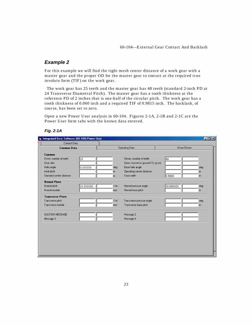
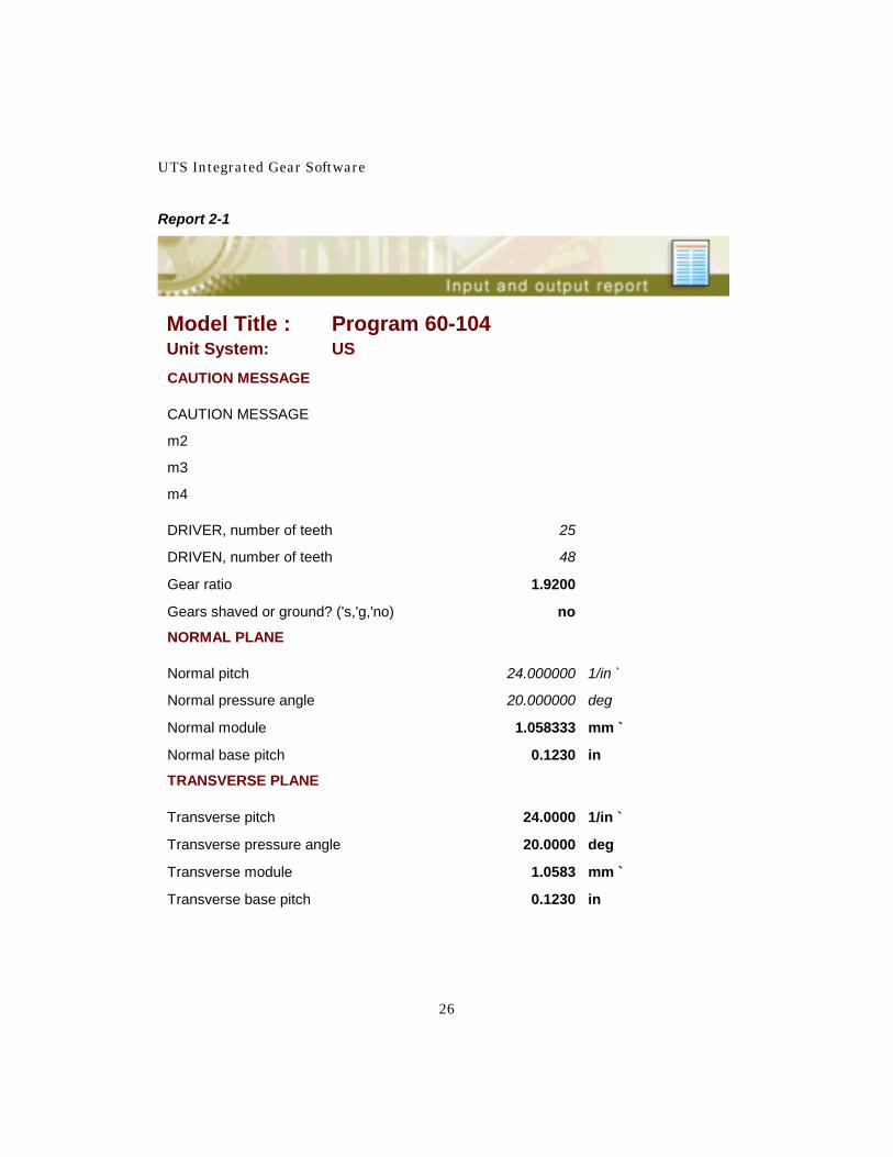
Example 2 For this example we will find the tight mesh center distance of a work gear with a master gear and the proper OD for the master gear to contact at the required true involute form (TIF) on the work gear. The work gear has 25 teeth and the master gear has 48 teeth (standard 2-inch PD at 24 Transverse Diametral Pitch). The master gear has a tooth thickness at the reference PD of 2 inches that is one-half of the circular pitch. The work gear has a tooth thickness of 0.060 inch and a required TIF of 0.9815 inch. The backlash, of course, has been set to zero. Open a new Power User analysis in 60-104. Figures 2-1A, 2-1B and 2-1C are the Power User form tabs with the known data entered. Fig. 2-1A

UTS Integrated Gear Software
24
Fig. 2-1B
60-104—External Gear Contact And Backlash
25
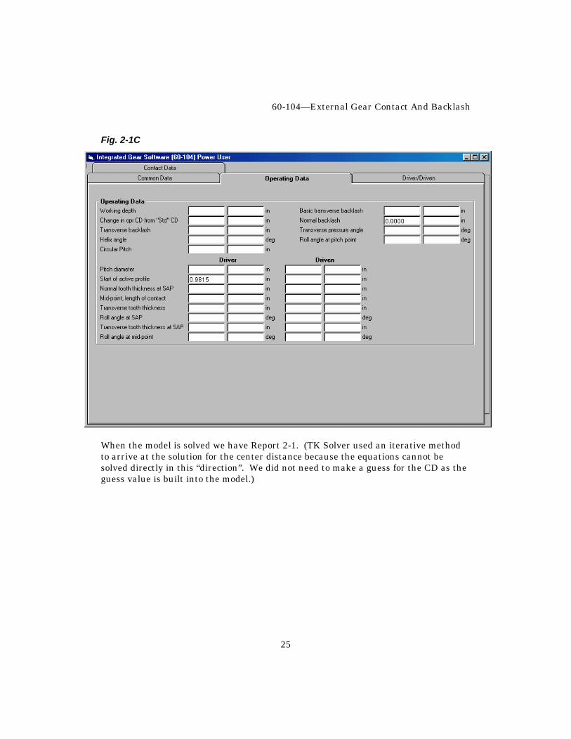
Fig. 2-1C
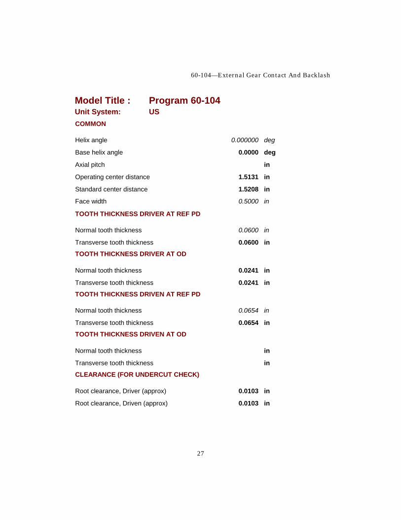
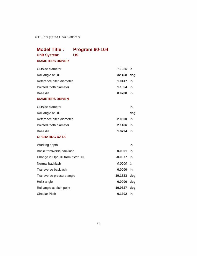
When the model is solved we have Report 2-1. (TK Solver used an iterative method to arrive at the solution for the center distance because the equations cannot be solved directly in this “direction”. We did not need to make a guess for the CD as the guess value is built into the model.)
UTS Integrated Gear Software
26
Report 2-1
Model Title : Program 60-104 Unit System: US CAUTION MESSAGE
CAUTION MESSAGE
m2
m3
m4
DRIVER, number of teeth 25
DRIVEN, number of teeth 48
Gear ratio 1.9200
Gears shaved or ground? ('s,'g,'no) no
NORMAL PLANE
Normal pitch 24.000000 1/in `
Normal pressure angle 20.000000 deg
Normal module 1.058333 mm `
Normal base pitch 0.1230 in
TRANSVERSE PLANE
Transverse pitch 24.0000 1/in `
Transverse pressure angle 20.0000 deg
Transverse module 1.0583 mm `
Transverse base pitch 0.1230 in
60-104—External Gear Contact And Backlash
27
Model Title : Program 60-104 Unit System: US COMMON
Helix angle 0.000000 deg
Base helix angle 0.0000 deg
Axial pitch in
Operating center distance 1.5131 in
Standard center distance 1.5208 in
Face width 0.5000 in
TOOTH THICKNESS DRIVER AT REF PD
Normal tooth thickness 0.0600 in
Transverse tooth thickness 0.0600 in
TOOTH THICKNESS DRIVER AT OD
Normal tooth thickness 0.0241 in
Transverse tooth thickness 0.0241 in
TOOTH THICKNESS DRIVEN AT REF PD
Normal tooth thickness 0.0654 in
Transverse tooth thickness 0.0654 in
TOOTH THICKNESS DRIVEN AT OD
Normal tooth thickness in
Transverse tooth thickness in
CLEARANCE (FOR UNDERCUT CHECK)
Root clearance, Driver (approx) 0.0103 in
Root clearance, Driven (approx) 0.0103 in
UTS Integrated Gear Software
28
Model Title : Program 60-104 Unit System: US DIAMETERS DRIVER
Outside diameter 1.1250 in
Roll angle at OD 32.458 deg
Reference pitch diameter 1.0417 in
Pointed tooth diameter 1.1654 in
Base dia 0.9788 in
DIAMETERS DRIVEN
Outside diameter in
Roll angle at OD deg
Reference pitch diameter 2.0000 in
Pointed tooth diameter 2.1466 in
Base dia 1.8794 in
OPERATING DATA
Working depth in
Basic transverse backlash 0.0001 in
Change in Opr CD from "Std" CD -0.0077 in
Normal backlash 0.0000 in
Transverse backlash 0.0000 in
Transverse pressure angle 19.1823 deg
Helix angle 0.0000 deg
Roll angle at pitch point 19.9327 deg
Circular Pitch 0.1302 in

60-104—External Gear Contact And Backlash
29
Model Title : Program 60-104 Unit System: US OPERATING DATA DRIVER
Pitch diameter 1.0364 in
Transverse tooth thickness 0.0616 in
Start of active profile 0.9815 in
Roll angle at SAP 4.2217 deg
Normal tooth thickness at SAP 0.0710 in
Transverse tooth thickness at SAP 0.0710 in
Mid-point, length of contact 1.0278 in
Roll angle at mid-point 18.340 deg
OPERATING DATA DRIVEN
Pitch diameter 1.9899 in
Transverse tooth thickness 0.0687 in
Start of active profile 1.9302 in
Roll angle at SAP 13.4092 deg
Normal tooth thickness at SAP 0.0839 in
Transverse tooth thickness at SAP 0.0839 in
Mid-point, length of contact 1.9990 in
Roll angle at mid-point 20.762 deg
CONTACT LENGTH
Length of contact, transverse plane 0.2412 in
Approach action 55.64 %
Recess action 44.36 %
UTS Integrated Gear Software
30
Model Title : Program 60-104 Unit System: US CONTACT RATIOS
Profile 1.9608
Helical 0.0000
Total 1.9608
LINES OF CONTACT ACROSS TEETH
Max total length 1.0000 in
Min total length 0.5000 in
Ratio: (Max length / Min length) 2.0000
SPECIFIC SLIDING RATIOS
Driver start of active profile 5.660
Driver outside diameter 0.587
Driven start of active profile
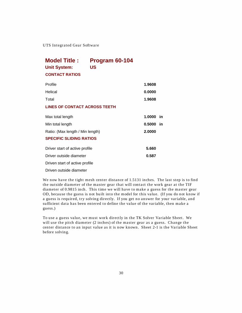
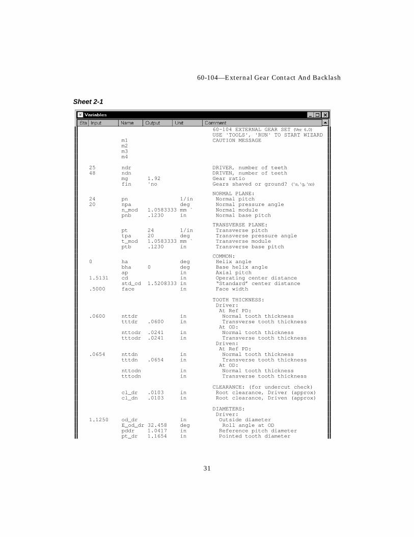
Driven outside diameter We now have the tight mesh center distance of 1.5131 inches. The last step is to find the outside diameter of the master gear that will contact the work gear at the TIF diameter of 0.9815 inch. This time we will have to make a guess for the master gear OD, because the guess is not built into the model for this value. (If you do not know if a guess is required, try solving directly. If you get no answer for your variable, and sufficient data has been entered to define the value of the variable, then make a guess.) To use a guess value, we must work directly in the TK Solver Variable Sheet. We will use the pitch diameter (2 inches) of the master gear as a guess. Change the center distance to an input value as it is now known. Sheet 2-1 is the Variable Sheet before solving.
60-104—External Gear Contact And Backlash
31
Sheet 2-1
60-104 EXTERNAL GEAR SET (Ver 6.0)USE 'TOOLS', 'RUN' TO START WIZARD
m1 CAUTION MESSAGEm2m3m4
25 ndr DRIVER, number of teeth48 ndn DRIVEN, number of teeth
mg 1.92 Gear ratiofin 'no Gears shaved or ground? ('s,'g,'no)
NORMAL PLANE:24 pn 1/in Normal pitch20 npa deg Normal pressure angle
n_mod 1.0583333 mm ` Normal modulepnb .1230 in Normal base pitch
TRANSVERSE PLANE:pt 24 1/in Transverse pitchtpa 20 deg Transverse pressure anglet_mod 1.0583333 mm ` Transverse moduleptb .1230 in Transverse base pitch
COMMON:0 ha deg Helix angle
bha 0 deg Base helix angleap in Axial pitch
1.5131 cd in Operating center distancestd_cd 1.5208333 in “Standard” center distance
.5000 face in Face width
TOOTH THICKNESS:Driver:At Ref PD:
.0600 nttdr in Normal tooth thicknesstttdr .0600 in Transverse tooth thickness
At OD:nttodr .0241 in Normal tooth thicknesstttodr .0241 in Transverse tooth thickness
Driven:At Ref PD:
.0654 nttdn in Normal tooth thicknesstttdn .0654 in Transverse tooth thickness
At OD:nttodn in Normal tooth thicknesstttodn in Transverse tooth thickness
CLEARANCE: (for undercut check)cl_dr .0103 in Root clearance, Driver (approx)cl_dn .0103 in Root clearance, Driven (approx)
DIAMETERS:Driver:
1.1250 od_dr in Outside diameterE_od_dr 32.458 deg Roll angle at ODpddr 1.0417 in Reference pitch diameterpt_dr 1.1654 in Pointed tooth diameter
UTS Integrated Gear Software
32
db_dr .9788 in Base diaDriven:
G 2.0000 od_dn in Outside diameterE_od_dn deg Roll angle at ODpddn 2.0000 in Reference pitch diameterpt_dn 2.1466 in Pointed tooth diameterdb_dn 1.8794 in Base dia
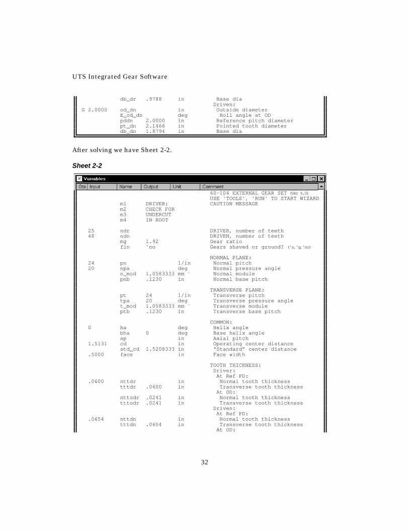
After solving we have Sheet 2-2. Sheet 2-2
60-104 EXTERNAL GEAR SET (Ver 6.0)USE 'TOOLS', 'RUN' TO START WIZARD
m1 DRIVER: CAUTION MESSAGEm2 CHECK FORm3 UNDERCUTm4 IN ROOT
25 ndr DRIVER, number of teeth48 ndn DRIVEN, number of teeth
mg 1.92 Gear ratiofin 'no Gears shaved or ground? ('s,'g,'no)
NORMAL PLANE:24 pn 1/in Normal pitch20 npa deg Normal pressure angle
n_mod 1.0583333 mm ` Normal modulepnb .1230 in Normal base pitch
TRANSVERSE PLANE:pt 24 1/in Transverse pitchtpa 20 deg Transverse pressure anglet_mod 1.0583333 mm ` Transverse moduleptb .1230 in Transverse base pitch
COMMON:0 ha deg Helix angle
bha 0 deg Base helix angleap in Axial pitch
1.5131 cd in Operating center distancestd_cd 1.5208333 in “Standard” center distance
.5000 face in Face width
TOOTH THICKNESS:Driver:At Ref PD:
.0600 nttdr in Normal tooth thicknesstttdr .0600 in Transverse tooth thickness
At OD:nttodr .0241 in Normal tooth thicknesstttodr .0241 in Transverse tooth thickness
Driven:At Ref PD:
.0654 nttdn in Normal tooth thicknesstttdn .0654 in Transverse tooth thickness
At OD:
60-104—External Gear Contact And Backlash
33
nttodn .0274 in Normal tooth thicknesstttodn .0274 in Transverse tooth thickness
CLEARANCE: (for undercut check)cl_dr .0103 in Root clearance, Driver (approx)cl_dn .0103 in Root clearance, Driven (approx)
DIAMETERS:Driver:
1.1250 od_dr in Outside diameterE_od_dr 32.458 deg Roll angle at ODpddr 1.0417 in Reference pitch diameterpt_dr 1.1654 in Pointed tooth diameterdb_dr .9788 in Base dia
Driven:od_dn 2.0935 in Outside diameterE_od_dn 28.116 deg Roll angle at ODpddn 2.0000 in Reference pitch diameterpt_dn 2.1466 in Pointed tooth diameterdb_dn 1.8794 in Base dia
OPERATING DATA:work .0961 in Working depthbtbl .0001 in Basic transverse backlashdelta -.0077 in Change in Opr CD from “Std” CD
0 nbl in Normal backlashtbl 0 in Transverse backlashtpa` 19.1823 deg Transverse pressure angleha` 0 deg Helix angleE_pd` 19.9327 deg Roll angle at pitch pointpitch` .1302 in Circular Pitch
Driver:pddr` 1.0364 in Pitch diametertttdr` .0616 in Transverse tooth thickness
.9815 sap_dr in Start of active profileE_ld_dr 4.2217 deg Roll angle at SAPnttlddr .0710 in Normal tooth thickness at SAPtttlddr .0710 in Transverse tooth thickness at SAPdcm_dr 1.0278 in Mid-point, length of contactE_cm_dr 18.340 deg Roll angle at mid-point
Driven:pddn` 1.9899 in Pitch diametertttdn` .0687 in Transverse tooth thicknesssap_dn 1.9302 in Start of active profileE_ld_dn 13.4092 deg Roll angle at SAPnttlddn .0839 in Normal tooth thickness at SAPtttlddn .0839 in Transverse tooth thickness at SAPdcm_dn 1.9990 in Mid-point, length of contactE_cm_dn 20.762 deg Roll angle at mid-point
Contact Length:z .2412 in Length of contact, transverse planeapr 55.64 % Approach actionrec 44.36 % Recess action
Contact Ratios:mp 1.9608 Profilemh 0 Helicalmt 1.9608 Total
Lines of Contact Across Teeth:Lcmax 1.0000 in Max total lengthLcmin .5000 in Min total lengthLcratio 2.0000 Ratio: (Max length / Min length)
UTS Integrated Gear Software
34
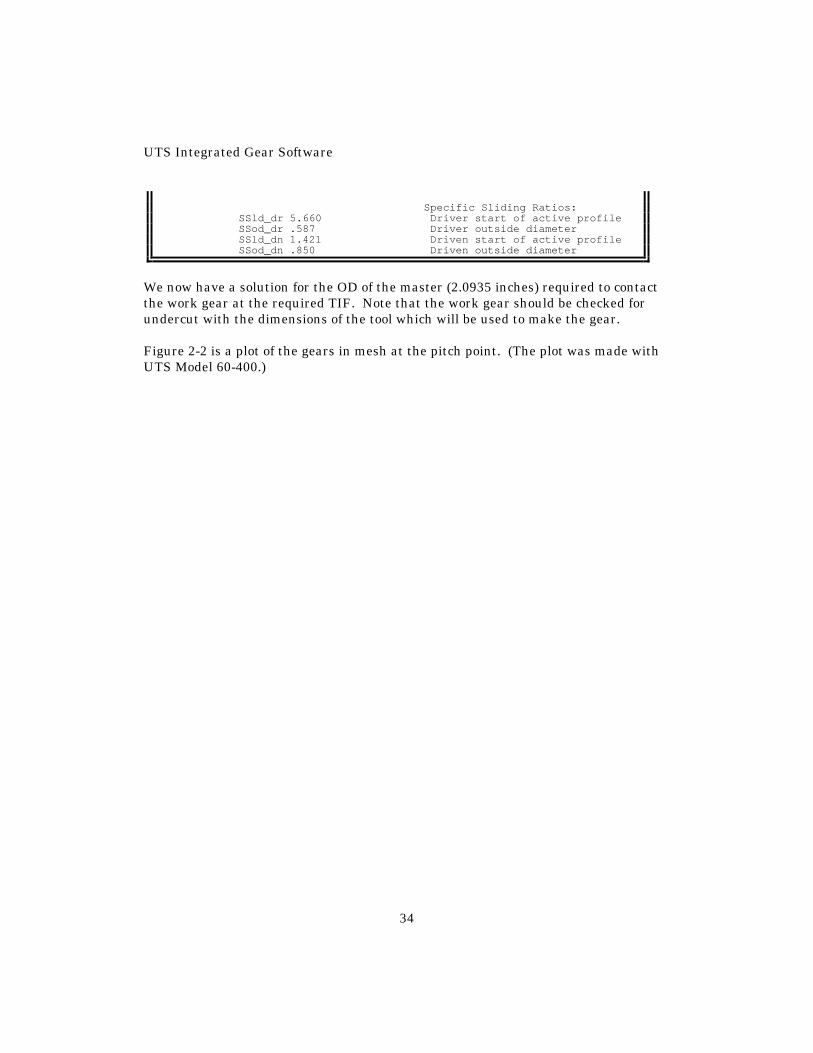
Specific Sliding Ratios:SSld_dr 5.660 Driver start of active profileSSod_dr .587 Driver outside diameterSSld_dn 1.421 Driven start of active profileSSod_dn .850 Driven outside diameter
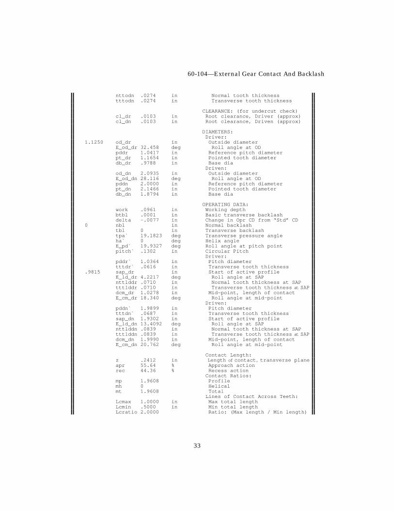
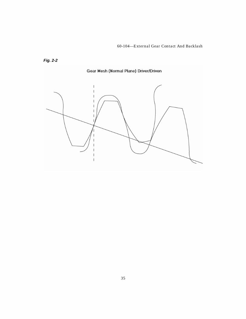
We now have a solution for the OD of the master (2.0935 inches) required to contact the work gear at the required TIF. Note that the work gear should be checked for undercut with the dimensions of the tool which will be used to make the gear. Figure 2-2 is a plot of the gears in mesh at the pitch point. (The plot was made with UTS Model 60-400.)
60-104—External Gear Contact And Backlash
35
Fig. 2-2
UTS Integrated Gear Software
36
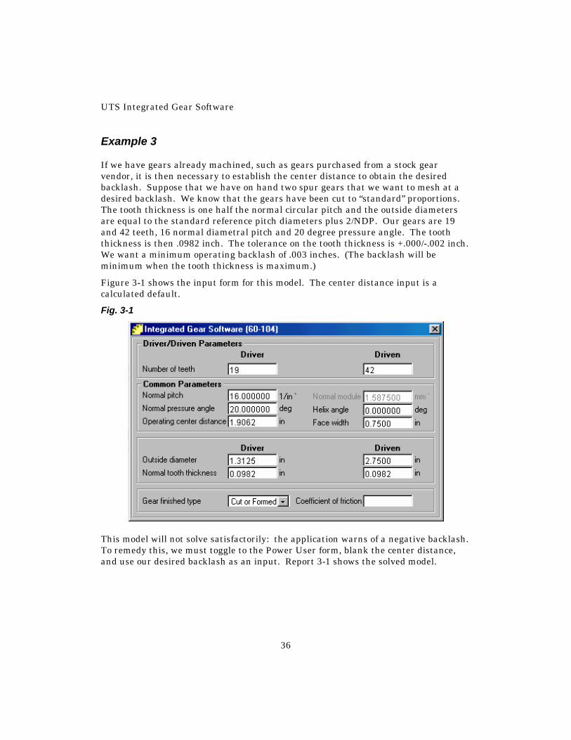
Example 3 If we have gears already machined, such as gears purchased from a stock gear vendor, it is then necessary to establish the center distance to obtain the desired backlash. Suppose that we have on hand two spur gears that we want to mesh at a desired backlash. We know that the gears have been cut to “standard” proportions. The tooth thickness is one half the normal circular pitch and the outside diameters are equal to the standard reference pitch diameters plus 2/NDP. Our gears are 19 and 42 teeth, 16 normal diametral pitch and 20 degree pressure angle. The tooth thickness is then .0982 inch. The tolerance on the tooth thickness is +.000/-.002 inch. We want a minimum operating backlash of .003 inches. (The backlash will be minimum when the tooth thickness is maximum.)
Figure 3-1 shows the input form for this model. The center distance input is a calculated default.
Fig. 3-1
This model will not solve satisfactorily: the application warns of a negative backlash. To remedy this, we must toggle to the Power User form, blank the center distance, and use our desired backlash as an input. Report 3-1 shows the solved model.
60-104—External Gear Contact And Backlash
37
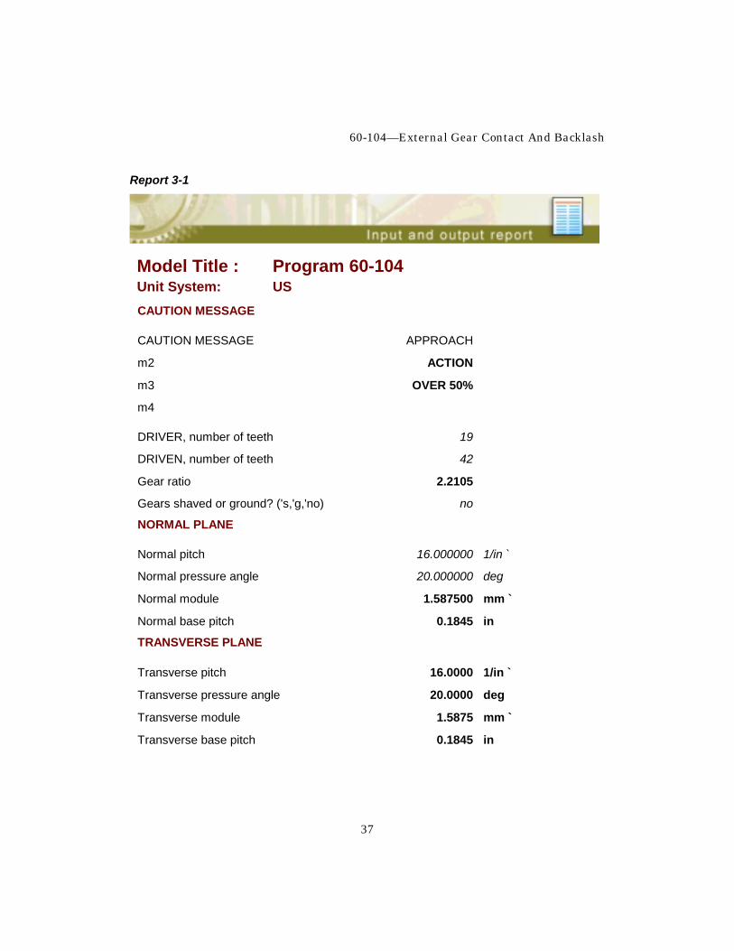
Report 3-1
Model Title : Program 60-104 Unit System: US CAUTION MESSAGE
CAUTION MESSAGE APPROACH
m2 ACTION
m3 OVER 50%
m4
DRIVER, number of teeth 19
DRIVEN, number of teeth 42
Gear ratio 2.2105
Gears shaved or ground? ('s,'g,'no) no
NORMAL PLANE
Normal pitch 16.000000 1/in `
Normal pressure angle 20.000000 deg
Normal module 1.587500 mm `
Normal base pitch 0.1845 in
TRANSVERSE PLANE
Transverse pitch 16.0000 1/in `
Transverse pressure angle 20.0000 deg
Transverse module 1.5875 mm `
Transverse base pitch 0.1845 in
UTS Integrated Gear Software
38
Model Title : Program 60-104 Unit System: US COMMON
Helix angle 0.000000 deg
Base helix angle 0.0000 deg
Axial pitch in
Operating center distance 1.9104 in
Standard center distance 1.9063 in
Face width 0.7500 in
TOOTH THICKNESS DRIVER AT REF PD
Normal tooth thickness 0.0982 in
Transverse tooth thickness 0.0982 in
TOOTH THICKNESS DRIVER AT OD
Normal tooth thickness 0.0431 in
Transverse tooth thickness 0.0431 in
TOOTH THICKNESS DRIVEN AT REF PD
Normal tooth thickness 0.0982 in
Transverse tooth thickness 0.0982 in
TOOTH THICKNESS DRIVEN AT OD
Normal tooth thickness 0.0478 in
Transverse tooth thickness 0.0478 in
CLEARANCE (FOR UNDERCUT CHECK)
Root clearance, Driver (approx) 0.0156 in
Root clearance, Driven (approx) 0.0156 in
60-104—External Gear Contact And Backlash
39
Model Title : Program 60-104 Unit System: US DIAMETERS DRIVER
Outside diameter 1.3125 in
Roll angle at OD 35.479 deg
Reference pitch diameter 1.1875 in
Pointed tooth diameter 1.3781 in
Base dia 1.1159 in
DIAMETERS DRIVEN
Outside diameter 2.7500 in
Roll angle at OD 28.238 deg
Reference pitch diameter 2.6250 in
Pointed tooth diameter 2.8412 in
Base dia 2.4667 in
OPERATING DATA
Working depth 0.1209 in
Basic transverse backlash 0.0000 in
Change in Opr CD from "Std" CD 0.0041 in
Normal backlash 0.0030 in
Transverse backlash 0.0030 in
Transverse pressure angle 20.3390 deg
Helix angle 0.0000 deg
Roll angle at pitch point 21.2387 deg
Circular Pitch 0.1968 in

UTS Integrated Gear Software
40
Model Title : Program 60-104 Unit System: US OPERATING DATA DRIVER
Pitch diameter 1.1901 in
Transverse tooth thickness 0.0975 in
Start of active profile 1.1215 in
Roll angle at SAP 5.7667 deg
Normal tooth thickness at SAP 0.1091 in
Transverse tooth thickness at SAP 0.1091 in
Mid-point, length of contact 1.1860 in
Roll angle at mid-point 20.623 deg
OPERATING DATA DRIVEN
Pitch diameter 2.6307 in
Transverse tooth thickness 0.0963 in
Start of active profile 2.5476 in
Roll angle at SAP 14.7967 deg
Normal tooth thickness at SAP 0.1192 in
Transverse tooth thickness at SAP 0.1192 in
Mid-point, length of contact 2.6349 in
Roll angle at mid-point 21.517 deg
CONTACT LENGTH
Length of contact, transverse plane 0.2893 in
Approach action 52.07 %
Recess action 47.93 %

60-104—External Gear Contact And Backlash
41
Model Title : Program 60-104 Unit System: US CONTACT RATIOS
Profile 1.5681
Helical 0.0000
Total 1.5681
LINES OF CONTACT ACROSS TEETH
Max total length 1.5000 in
Min total length 0.7500 in
Ratio: (Max length / Min length) 2.0000
SPECIFIC SLIDING RATIOS
Driver start of active profile 3.897
Driver outside diameter 0.583
Driven start of active profile 1.398
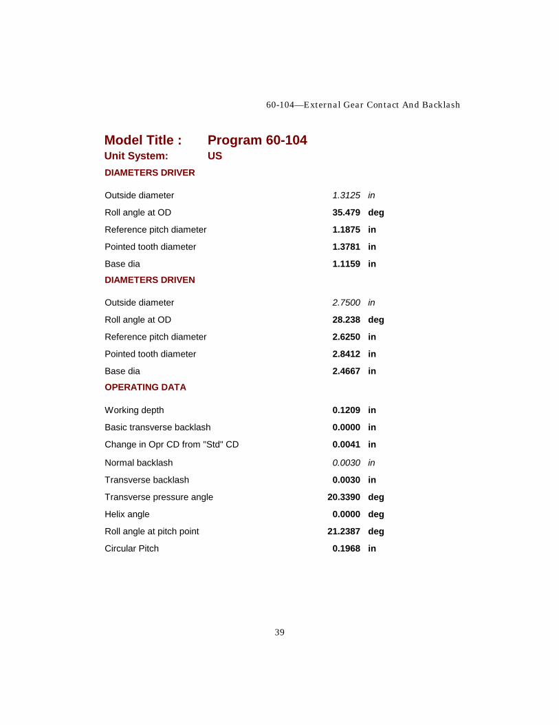
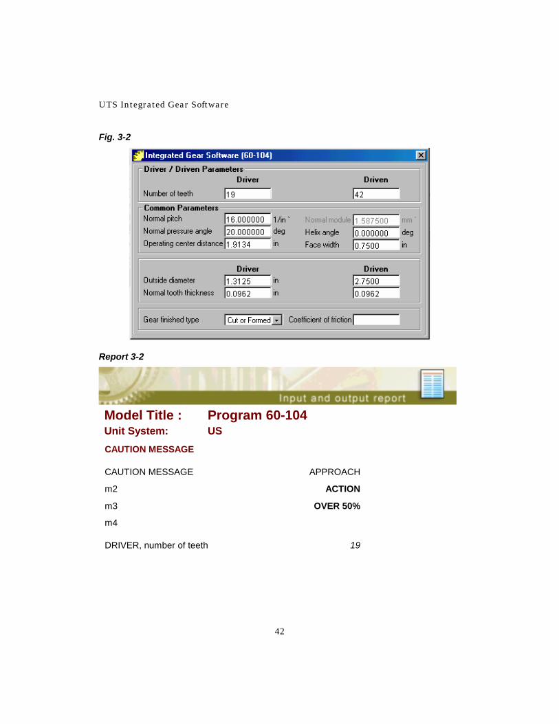
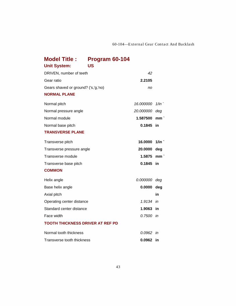
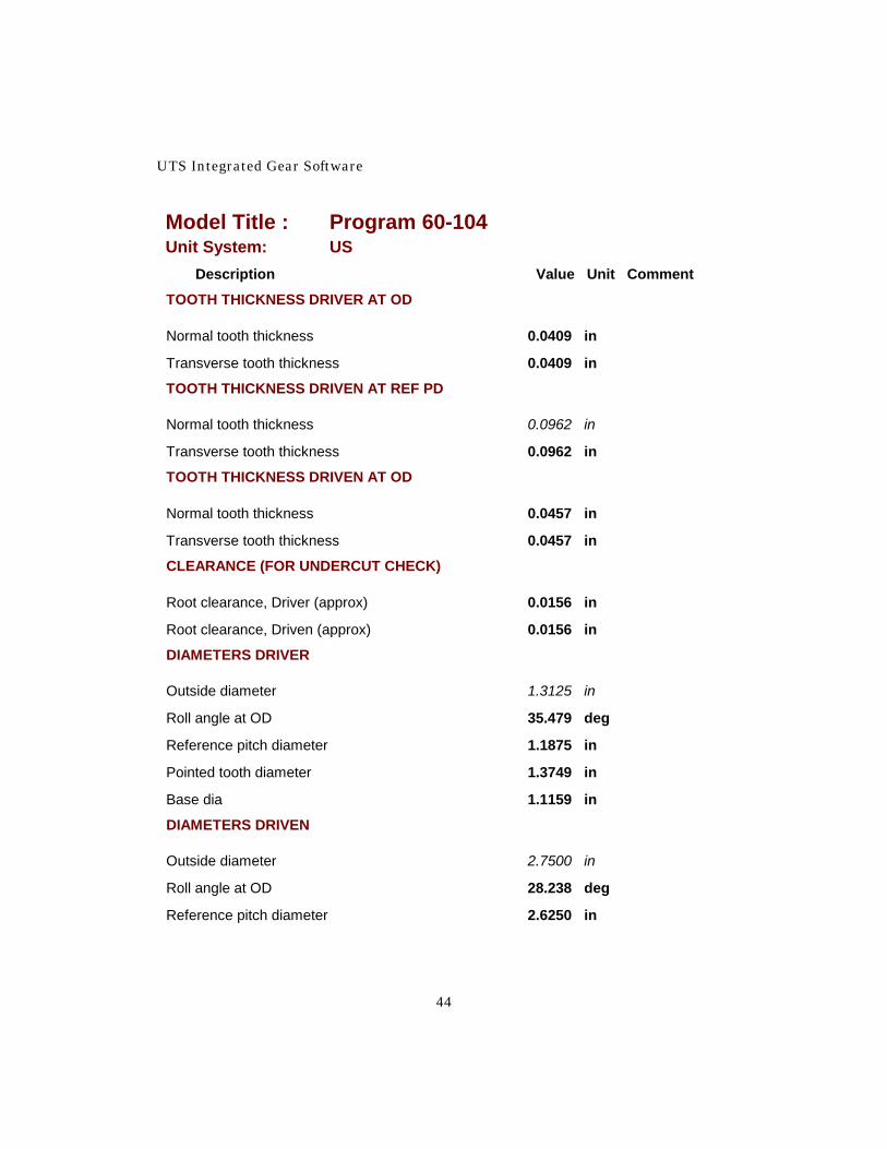
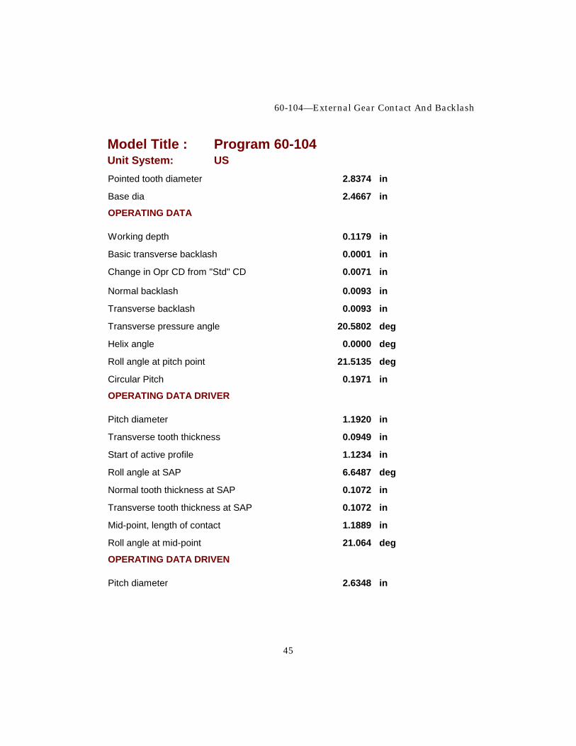
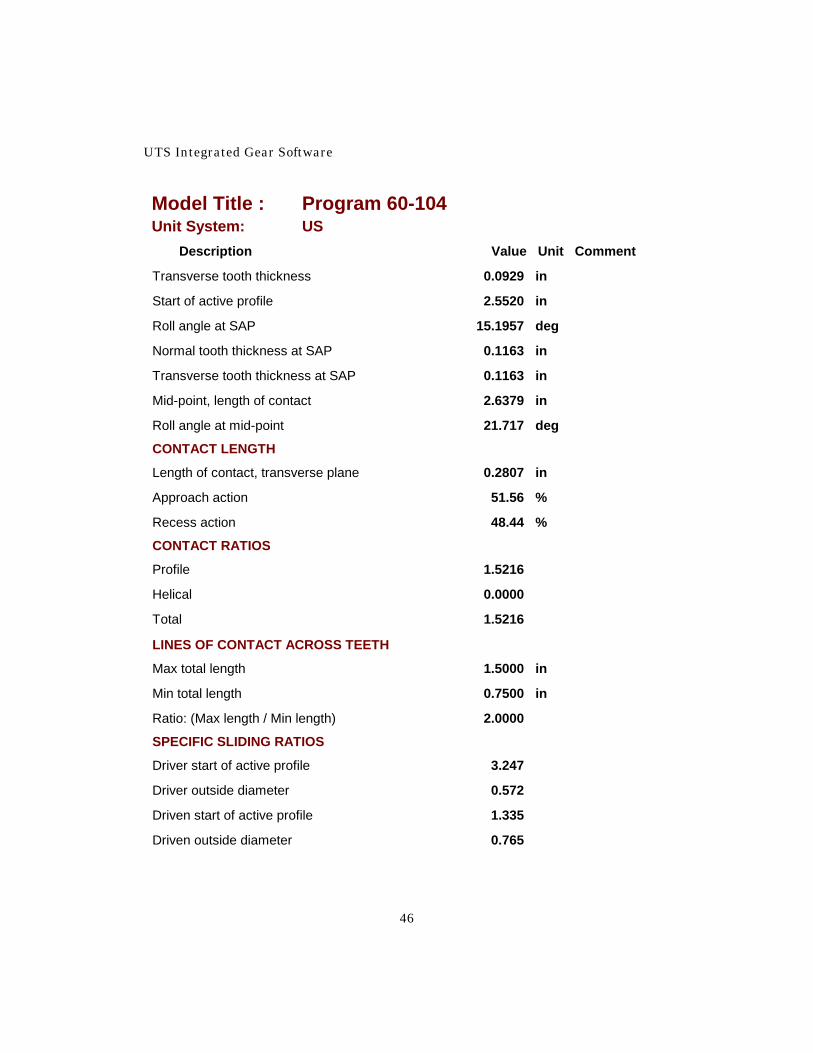
Driven outside diameter 0.796 Note that the approach action is a little higher than the recess action and the maximum specific sliding is well over three (almost 4). Both of these conditions are not uncommon when using “stock” gears. We see that to obtain .003 inch backlash when the tooth thickness is maximum the gears will have to be mounted on a center distance of 1.9104 inches. Because we need a tolerance for the center distance and we have a tolerance on the tooth thickness, it will be necessary to solve the model in another direction to find the maximum possible backlash. The tolerance on the center distance will be +.003/-.000 inches and the minimum tooth thickness will be .0962 inches. Enter the new center distance of 1.9134 inches and the new tooth thickness of .0982 inch. For these inputs we will revert to the input form. Figure 3-2 shows it with the required inputs. Report 3-2 shows the model after solving.
UTS Integrated Gear Software
42
Fig. 3-2
Report 3-2
Model Title : Program 60-104 Unit System: US CAUTION MESSAGE
CAUTION MESSAGE APPROACH
m2 ACTION
m3 OVER 50%
m4
DRIVER, number of teeth 19
60-104—External Gear Contact And Backlash
43
Model Title : Program 60-104 Unit System: US DRIVEN, number of teeth 42
Gear ratio 2.2105
Gears shaved or ground? ('s,'g,'no) no
NORMAL PLANE
Normal pitch 16.000000 1/in `
Normal pressure angle 20.000000 deg
Normal module 1.587500 mm `
Normal base pitch 0.1845 in
TRANSVERSE PLANE
Transverse pitch 16.0000 1/in `
Transverse pressure angle 20.0000 deg
Transverse module 1.5875 mm `
Transverse base pitch 0.1845 in
COMMON
Helix angle 0.000000 deg
Base helix angle 0.0000 deg
Axial pitch in
Operating center distance 1.9134 in
Standard center distance 1.9063 in
Face width 0.7500 in
TOOTH THICKNESS DRIVER AT REF PD
Normal tooth thickness 0.0962 in
Transverse tooth thickness 0.0962 in
UTS Integrated Gear Software
44
Model Title : Program 60-104 Unit System: US Description Value Unit Comment
TOOTH THICKNESS DRIVER AT OD
Normal tooth thickness 0.0409 in
Transverse tooth thickness 0.0409 in
TOOTH THICKNESS DRIVEN AT REF PD
Normal tooth thickness 0.0962 in
Transverse tooth thickness 0.0962 in
TOOTH THICKNESS DRIVEN AT OD
Normal tooth thickness 0.0457 in
Transverse tooth thickness 0.0457 in
CLEARANCE (FOR UNDERCUT CHECK)
Root clearance, Driver (approx) 0.0156 in
Root clearance, Driven (approx) 0.0156 in
DIAMETERS DRIVER
Outside diameter 1.3125 in
Roll angle at OD 35.479 deg
Reference pitch diameter 1.1875 in
Pointed tooth diameter 1.3749 in
Base dia 1.1159 in
DIAMETERS DRIVEN
Outside diameter 2.7500 in
Roll angle at OD 28.238 deg
Reference pitch diameter 2.6250 in
60-104—External Gear Contact And Backlash
45
Model Title : Program 60-104 Unit System: US Pointed tooth diameter 2.8374 in
Base dia 2.4667 in
OPERATING DATA
Working depth 0.1179 in
Basic transverse backlash 0.0001 in
Change in Opr CD from "Std" CD 0.0071 in
Normal backlash 0.0093 in
Transverse backlash 0.0093 in
Transverse pressure angle 20.5802 deg
Helix angle 0.0000 deg
Roll angle at pitch point 21.5135 deg
Circular Pitch 0.1971 in
OPERATING DATA DRIVER
Pitch diameter 1.1920 in
Transverse tooth thickness 0.0949 in
Start of active profile 1.1234 in
Roll angle at SAP 6.6487 deg
Normal tooth thickness at SAP 0.1072 in
Transverse tooth thickness at SAP 0.1072 in
Mid-point, length of contact 1.1889 in
Roll angle at mid-point 21.064 deg
OPERATING DATA DRIVEN
Pitch diameter 2.6348 in
UTS Integrated Gear Software
46
Model Title : Program 60-104 Unit System: US Description Value Unit Comment
Transverse tooth thickness 0.0929 in
Start of active profile 2.5520 in
Roll angle at SAP 15.1957 deg
Normal tooth thickness at SAP 0.1163 in
Transverse tooth thickness at SAP 0.1163 in
Mid-point, length of contact 2.6379 in
Roll angle at mid-point 21.717 deg
CONTACT LENGTH
Length of contact, transverse plane 0.2807 in
Approach action 51.56 %
Recess action 48.44 %
CONTACT RATIOS
Profile 1.5216
Helical 0.0000
Total 1.5216
LINES OF CONTACT ACROSS TEETH
Max total length 1.5000 in
Min total length 0.7500 in
Ratio: (Max length / Min length) 2.0000
SPECIFIC SLIDING RATIOS
Driver start of active profile 3.247
Driver outside diameter 0.572
Driven start of active profile 1.335
Driven outside diameter 0.765

60-104—External Gear Contact And Backlash
47
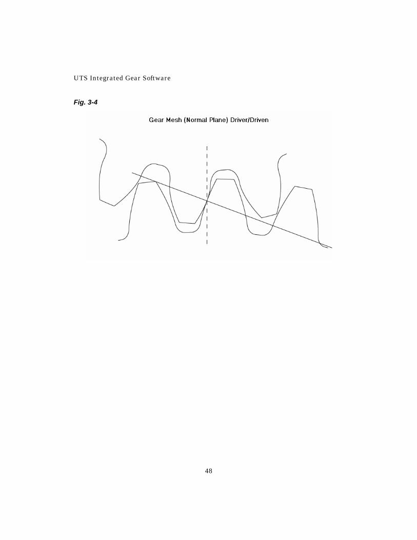
Under these conditions the maximum possible backlash will be .007 inch. (Actually, the probability of having maximum or minimum backlash in any assembly is quite small.) Figure 3-3 is a plot of the gears in mesh at the pitch point at minimum center distance of 1.9104 inches. Figure 3-4 shows the gears in mesh at the pitch point at the maximum center distance of 1.9134 inches. (The plots were made with UTS Model 60-400.) Fig. 3-3
UTS Integrated Gear Software
48
Fig. 3-4


![Bifurcation and Chaos of Gear Pair System Supported by ... · mesh stiffness, damping, gear errors profile modification and backlash. Cai and Hayashi [9] calculated the opti- mum](https://static.fdocuments.in/doc/165x107/5ec58b34a482d05ea361c337/bifurcation-and-chaos-of-gear-pair-system-supported-by-mesh-stiffness-damping.jpg)