
PROFINET – SD6 Operating manual
63
PROFINET – SD6 Operating manual en-US 11/2019 ID 442710.03
Transcript of PROFINET – SD6 Operating manual

PROFINET – SD6Operating manual
en-US11/2019 ID 442710.03

Table of contents STOBER
ii
11/2
019
| ID
442
710.
03
Table of contents1 Foreword .................................................................................................................................................................. 5
2 User information ....................................................................................................................................................... 6
2.1 Storage and transfer ................................................................................................................................................ 6
2.2 Described product.................................................................................................................................................... 6
2.3 Timeliness ................................................................................................................................................................ 6
2.4 Original language ..................................................................................................................................................... 6
2.5 Limitation of liability ................................................................................................................................................ 6
2.6 Formatting conventions........................................................................................................................................... 6
2.6.1 Use of symbols........................................................................................................................................ 7
2.6.2 Markup of text elements ........................................................................................................................ 8
2.6.3 Mathematics and formulas..................................................................................................................... 8
2.7 Trademarks .............................................................................................................................................................. 9
3 General safety instructions...................................................................................................................................... 10
3.1 Directives and standards........................................................................................................................................ 10
3.2 Qualified personnel................................................................................................................................................ 10
3.3 Intended use .......................................................................................................................................................... 10
3.4 Operational environment and operation............................................................................................................... 10
3.5 Disposal.................................................................................................................................................................. 11
4 Network structure ................................................................................................................................................... 12
5 PN6 communication module ................................................................................................................................... 13
5.1 Installation ............................................................................................................................................................. 13
6 Connection.............................................................................................................................................................. 14
6.1 Selecting suitable lines........................................................................................................................................... 14
6.2 X200, X201: Fieldbus connection ........................................................................................................................... 14
7 What you should know before commissioning ........................................................................................................ 15
7.1 Program interfaces................................................................................................................................................. 15
7.1.1 DS6: Structure of the program interface .............................................................................................. 15
7.1.2 TIA Portal: Structure of the program interface..................................................................................... 17
7.2 Meaning of parameters ......................................................................................................................................... 19
7.2.1 Parameter groups ................................................................................................................................. 19
7.2.2 Parameter types and data types........................................................................................................... 20
7.2.3 Parameter types ................................................................................................................................... 21
7.2.4 Parameter structure ............................................................................................................................. 21
7.2.5 Parameter visibility ............................................................................................................................... 22
7.3 Power-loss protected storage................................................................................................................................ 22

STOBER Table of contents11
/201
9 |
ID 4
4271
0.03
iii
8 Commissioning ........................................................................................................................................................ 23
8.1 DS6: Configuring the drive controller .................................................................................................................... 24
8.1.1 Initiating the project ............................................................................................................................. 24
8.1.2 Parameterizing general PROFINET settings .......................................................................................... 26
8.1.3 Configuring PZD transmission............................................................................................................... 26
8.1.4 Transmitting and saving the configuration ........................................................................................... 28
8.2 TIA Portal: Setting up a PROFINET network ........................................................................................................... 30
8.2.1 Checking network addresses ................................................................................................................ 30
8.2.2 Installing the GSD file............................................................................................................................ 31
8.2.3 Mapping the PROFINET IO system........................................................................................................ 31
8.2.4 Configuring the IO controller ................................................................................................................ 32
8.2.5 Configuring IO devices .......................................................................................................................... 32
8.2.6 Transmitting a project configuration .................................................................................................... 34
8.2.7 Testing communication ........................................................................................................................ 34
8.2.8 Programming acyclical communication services .................................................................................. 35
9 Monitoring and diagnostics ..................................................................................................................................... 36
9.1 Connection monitoring .......................................................................................................................................... 36
9.2 LED display ............................................................................................................................................................. 37
9.2.1 PROFINET state ..................................................................................................................................... 37
9.2.2 PROFINET network connection............................................................................................................. 38
9.3 Events..................................................................................................................................................................... 39
9.3.1 Event 52: Communication..................................................................................................................... 39
9.4 Parameters............................................................................................................................................................. 40
9.4.1 A270 | X20x state | V0.......................................................................................................................... 40
9.4.2 A271 | PN state | V0............................................................................................................................. 40
9.4.3 A272 | PN module/submodule | V1 ..................................................................................................... 40
9.4.4 A273 | PN device name | V0 ................................................................................................................ 40
9.4.5 A274 | PN IP address | V0 .................................................................................................................... 41
9.4.6 A275 | PN subnet mask | V0 ................................................................................................................ 41
9.4.7 A276 | PN gateway | V0 ....................................................................................................................... 41
9.4.8 A279 | PN MAC addresses | V0 ............................................................................................................ 41
10 More on PROFINET? ................................................................................................................................................ 42
10.1 PROFINET ............................................................................................................................................................... 42
10.2 Device classes ........................................................................................................................................................ 42
10.3 Communication...................................................................................................................................................... 43
10.3.1 Cyclical communication: Process data.................................................................................................. 43
10.3.2 Acyclical communication: Parameter channel data.............................................................................. 43
10.4 Communication protocols...................................................................................................................................... 47
10.5 Ethernet network addressing................................................................................................................................. 47
10.5.1 MAC address......................................................................................................................................... 47
10.5.2 IP address.............................................................................................................................................. 48
10.5.3 Subnet mask ......................................................................................................................................... 48
Table of contents STOBER
iv
11/2
019
| ID
442
710.
03
10.5.4 Subnets and gateways .......................................................................................................................... 48
10.5.5 MAC and IP addressing using device names......................................................................................... 48
11 Appendix................................................................................................................................................................. 49
11.1 Addressing parameters for RECORD record........................................................................................................... 49
11.1.1 Determining the Axis_number.............................................................................................................. 49
11.1.2 Calculating the Parameter_number ..................................................................................................... 49
11.1.3 Determining the subindex .................................................................................................................... 50
11.2 RDREC, WRREC: RECORD ....................................................................................................................................... 50
11.2.1 RECORD request: Header structure ...................................................................................................... 50
11.2.2 RECORD response: Header structure.................................................................................................... 51
11.2.3 Error codes............................................................................................................................................ 52
11.2.4 Attribute and format elements: Possible combinations....................................................................... 53
11.3 Process data modules ............................................................................................................................................ 54
11.4 Detailed information.............................................................................................................................................. 55
11.5 Abbreviations......................................................................................................................................................... 56
12 Contact.................................................................................................................................................................... 57
12.1 Consultation, service and address ......................................................................................................................... 57
12.2 Your opinion is important to us ............................................................................................................................. 57
12.3 Close to customers around the world.................................................................................................................... 58
Glossary .................................................................................................................................................................. 59
List of figures........................................................................................................................................................... 61
List of tables ............................................................................................................................................................ 62

STOBER 1 | Foreword11
/201
9 |
ID 4
4271
0.03
5
1 ForewordPROFINET, an open industrial Ethernet standard, is especially well-suited for applications that require fast communicationwith a high data rate combined with industrial IT functions. PROFINET is real-time capable and uses IT standards like TCP/IP while also allowing the integration of fieldbus systems.
The 6th generation of STOBER drive controllers support PROFINET IO, a development of the successful PROFIBUS DPstandard. The drive controllers are tailored for real-time communication of I/O data and offer the ability to transfer all required data,parameters and IT functions at the same time.
For drive controllers of the SD6 series, the fieldbus functionality is provided via the PN6 communication module.

2 | User information STOBER
6
11/2
019
| ID
442
710.
03
2 User informationThis documentation aids you in installing and connecting the PN6 communication module in order to connect a SD6 of thedrive controller series (IO device) to a PLC as an IO controller using the PROFINET IO bus system.
Technical knowledge
Operating a PROFINET network requires having familiarity with PROFINET network technology and the basics of theassociated Siemens SIMATIC automation systems.
Technical requirements
Before you begin operating your PROFINET network, you need to wire the drive controllers and initially check that they arefunctioning correctly. To do so, follow the instructions in the commissioning instructions for the SD6 drive controller.
2.1 Storage and transferAs this documentation contains important information for handling the product safely and efficiently, it must be stored inthe immediate vicinity of the product until product disposal and be accessible to qualified personnel at all times.
Also pass on this documentation if the product is transferred or sold to a third party.
2.2 Described productDrive controllers of the SD6 series in combination with the DriveControlSuite software (DS6) in V 6.4-D or later andassociated firmware in V 6.4-D or later.
2.3 TimelinessCheck whether this document is the latest version of the documentation. We make the latest document versions for ourproducts available for download on our website:http://www.stoeber.de/en/downloads/.
2.4 Original languageThe original language of this documentation is German; all other language versions are derived from the original language.
2.5 Limitation of liabilityThis documentation was created taking into account the applicable standards and regulations as well as the current state oftechnology.
STOBER shall assume no responsibility for damage resulting from failure to comply with the documentation or from usethat deviates from the intended use of the product. This is especially true for damage caused by individual technicalmodifications to the product or projecting and operation of the product by unqualified personnel.
2.6 Formatting conventionsOrientation guides in the form of signal words, symbols and special text markups are used to emphasize specificinformation so that you are able identify it in this documentation quickly.

STOBER 2 | User information11
/201
9 |
ID 4
4271
0.03
7
2.6.1 Use of symbolsSafety instructions are identified with the following symbols. They indicate special risks when handling the product and areaccompanied by relevant signal words that express the extent of the risk. Furthermore, useful tips and recommendationsfor efficient, error-free operation are specially highlighted.
ATTENTION!
Notice
This indicates that damage to property may occur
▪ if the stated precautionary measures are not taken.
CAUTION!
Caution
This word with a warning triangle indicates that minor personal injury may occur
▪ if the stated precautionary measures are not taken.
WARNING!
Warning
This word with a warning triangle means there may be a considerable risk of fatal injury
▪ if the stated precautionary measures are not taken.
DANGER!
Danger
This word with a warning triangle indicates that there is a considerable risk of fatal injury
▪ if the stated precautionary measures are not taken.
Information
Information indicates important information about the product or serves to emphasize a section in the documentation thatdeserves special attention from the reader.

2 | User information STOBER
8
11/2
019
| ID
442
710.
03
2.6.2 Markup of text elementsCertain elements of the continuous text are distinguished as follows.
Important information Words or expressions with a special meaning
Interpolated position mode Optional: File or product name or other name
Detailed information Internal cross-reference
http://www.samplelink.com External cross-reference
Software and displays
The following formatting is used to identify the various information content of elements referenced by the softwareinterface or a drive controller display, as well as any user entries.
Main menu Settings
Window names, dialog box names, page names or buttons, combinedproper nouns, functions referenced by the interface
Select Referencing method A
Predefined entry
Save your <own IP address>
User-defined entry
EVENT 52: COMMUNICATION
Display indicators (status, messages, warnings, faults) for statusinformation referenced by the interface
Keyboard shortcuts and command sequences or paths are represented as follows.
[CTRL], [CTRL] + [S] Key, shortcut
Table > Insert table Navigation to menus/submenus (path specification)
Interpretation of parameter identification
Parameter identification consists of the following elements, where short forms are also possible, i.e. only specifying acoordinate or the combination of coordinate and name.
E50 V0
Coordinate Name Version
Drive controller
2.6.3 Mathematics and formulasThe following signs are used to represent mathematical relationships and formulas.
- Subtraction
+ Addition
× Multiplication
÷ Division
| | Amount

STOBER 2 | User information11
/201
9 |
ID 4
4271
0.03
9
2.7 TrademarksThe following names used in connection with the device, its optional equipment and its accessories are trademarks orregistered trademarks of other companies:
Windows®,Windows® XP,Windows® 7,Windows® 10
Windows®, das Windows®-Logo, Windows® XP, Windows® 7 und Windows® 10 areregistered trademarks of Microsoft Corporation in the United States and/or othercountries.
PROFIBUS®, PROFINET®
The PROFIBUS and the PROFINET logo are registered trademarks of PROFIBUSNutzerorganisation e.V., Karlsruhe, Germany.
SIMATIC®, TIA Portal®
SIMATIC® and TIA Portal® are registered trademarks of Siemens AG, Munich,Germany.
All other trademarks not listed here are the property of their respective owners.
Products that are registered as trademarks are not specially indicated in this documentation. Existing property rights(patents, trademarks, protection of utility models) are to be observed.
3 | General safety instructions STOBER
10
11/2
019
| ID
442
710.
03
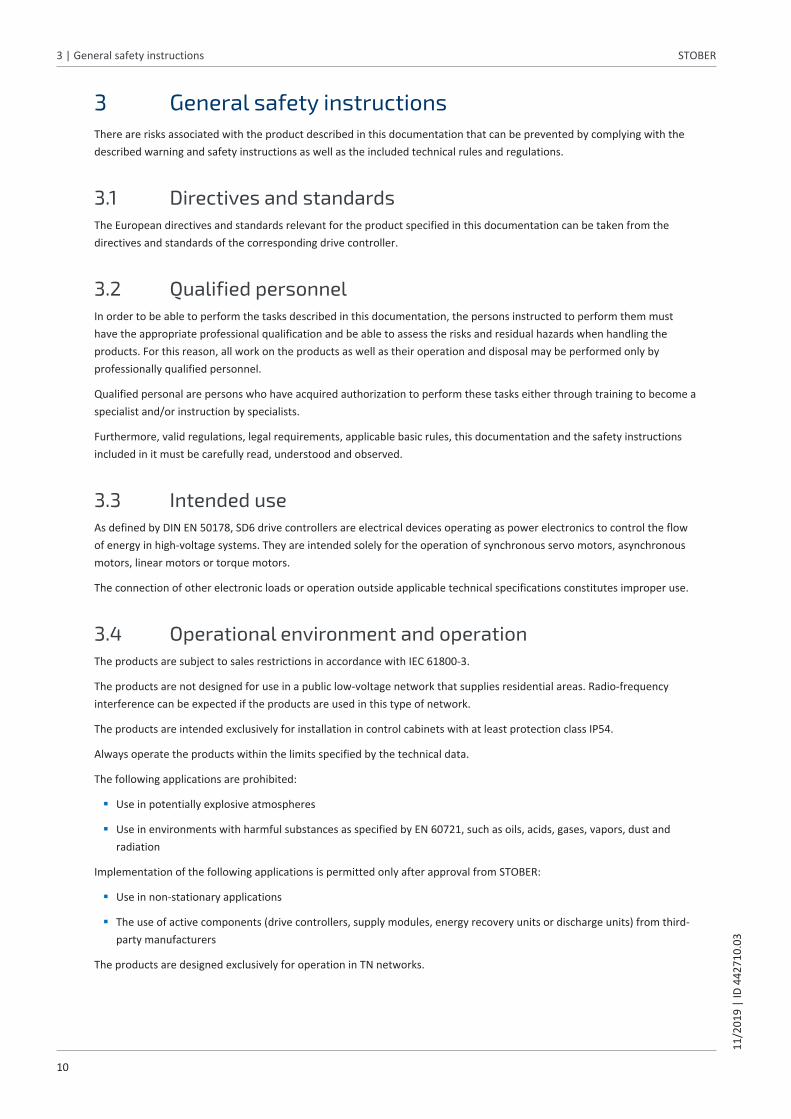
3 General safety instructionsThere are risks associated with the product described in this documentation that can be prevented by complying with thedescribed warning and safety instructions as well as the included technical rules and regulations.
3.1 Directives and standardsThe European directives and standards relevant for the product specified in this documentation can be taken from thedirectives and standards of the corresponding drive controller.
3.2 Qualified personnelIn order to be able to perform the tasks described in this documentation, the persons instructed to perform them musthave the appropriate professional qualification and be able to assess the risks and residual hazards when handling theproducts. For this reason, all work on the products as well as their operation and disposal may be performed only byprofessionally qualified personnel.
Qualified personal are persons who have acquired authorization to perform these tasks either through training to become aspecialist and/or instruction by specialists.
Furthermore, valid regulations, legal requirements, applicable basic rules, this documentation and the safety instructionsincluded in it must be carefully read, understood and observed.
3.3 Intended useAs defined by DIN EN 50178, SD6 drive controllers are electrical devices operating as power electronics to control the flowof energy in high-voltage systems. They are intended solely for the operation of synchronous servo motors, asynchronousmotors, linear motors or torque motors.
The connection of other electronic loads or operation outside applicable technical specifications constitutes improper use.
3.4 Operational environment and operationThe products are subject to sales restrictions in accordance with IEC 61800-3.
The products are not designed for use in a public low-voltage network that supplies residential areas. Radio-frequencyinterference can be expected if the products are used in this type of network.
The products are intended exclusively for installation in control cabinets with at least protection class IP54.
Always operate the products within the limits specified by the technical data.
The following applications are prohibited:
§ Use in potentially explosive atmospheres
§ Use in environments with harmful substances as specified by EN 60721, such as oils, acids, gases, vapors, dust andradiation
Implementation of the following applications is permitted only after approval from STOBER:
§ Use in non-stationary applications
§ The use of active components (drive controllers, supply modules, energy recovery units or discharge units) from third-party manufacturers
The products are designed exclusively for operation in TN networks.

STOBER 3 | General safety instructions11
/201
9 |
ID 4
4271
0.03
11
3.5 DisposalObserve the current national and regional regulations when disposing of the product! Dispose of the individual productparts depending on their properties, e.g. as:
§ Electronic waste (circuit boards)
§ Plastic
§ Sheet metal
§ Copper
§ Aluminum
§ Battery

4 | Network structure STOBER
12
11/2
019
| ID
442
710.
03
4 Network structureA PROFINET network generally consists of a PROFINET segment with an IO controller and all IO devices belonging to thisarea, i.e. drive controllers of the SD6 series and a PC as the IO supervisor.
The PROFINET network structure is generally tailored to the specific requirements of the respective system. STOBER drivecontrollers support a star, line or tree topology.
All IO standard devices are integrated into the PROFINET network using internal or external switches (100 Mbps).
You can configure and parameterize the drive controllers using the DS6 DriveControlSuite software from STOBER; SiemensTIA Portal lets you do this for the entire PROFINET network, for instance.
The following graphic presents an abstract of a PROFINET network; the devices displayed have internal switches.
PROFINET
IO devices3 x
IO controllerSIMATIC S7-1500
Com
man
d le
vel
Cont
rolle
r lev
el
IO supervisorcommissioning
Fiel
d le
vel
Commissioning
SD6 drive controllers
Fig. 1: PROFINET: Network structure

STOBER 5 | PN6 communication module11
/201
9 |
ID 4
4271
0.03
13
5 PN6 communication moduleThe drive controllers of the SD6 series are connected to a higher-level controller using PN6 communication modules, whichprovide the necessary fieldbus interfaces.
The communication modules match the PROFINET IO standard and enable cyclical and acyclical data exchange between thedrive controllers and the controller.
5.1 InstallationInstallation work is permitted only when no voltage is present. Observe the five safety rules.
Note the minimum clearances listed in the technical data during installation in order to prevent the drive controller fromoverheating.
Protect the device against falling parts (wire scraps, wires, pieces of metal, etc.) during installation or other work in thecontrol cabinet. Parts with conductive properties may result in a short circuit or failure inside the drive controller.
Remove the additional covers before commissioning so that the drive controller does not overheat.
DANGER!
Electrical voltage! Risk of fatal injury due to electric shock!
▪ Always switch off all power supply voltage before working on the devices!
▪ Note the discharge time of the DC link capacitors in the general technical data. You can only determine the absenceof voltage after this time period.
ATTENTION!
Damage to property due to electrostatic discharge!
Take appropriate measures when handling exposed circuit boards, e.g. wearing ESD-safe clothing.
Do not touch contact surfaces.
Tool and material
You will need:
§ A TORX screwdriver TX10
§ The cover and screws included with the communication module
Installation
1. Unscrew the fastening screw of the dummy cover on top of the drive controller and remove the cover.
2. Slide the communication module on the guide rails into the drive controller.
3. Press on the module in order to push the pin contacts into the box header.
4. Set the tabs of the cover included with the communication module in front in the notch at an angle.
5. Place the cover on the drive controller so that the tabs lie under the edge.
6. Attach the cover using both screws.

6 | Connection STOBER
14
11/2
019
| ID
442
710.
03
6 ConnectionFor network connection, PROFINET only allows switches; these in turn allow for flexible network topology and nearlyunlimited network expansion of several kilometers at maximum speed.
6.1 Selecting suitable linesThe PROFINET transmission technology is based on the Fast Ethernet standard.
A PROFINET network generally consists of symmetrical, shielded copper cables twisted in pairs (shielded twisted pair, CAT5e quality level).
Signals are transmitted according to the 100BASE TX method, i.e. with a transfer rate of 100 Mbps at a frequency of125 MHz. A maximum of 1440 bytes can be transferred per frame. The maximum cable length is 100 m.
PROFINET cables exist in different versions that are tailored to different application scenarios and ambient conditions.
We recommend using the cables specified in the PROFINET installation guidelines. They are adjusted for use in automationtechnology with regard to usage, resistance, EMC properties and color coding.
There are type A, B and C cables, differentiated by installation type:
§ Type A4-wire shielded copper cable for fixed installation
§ Type B4-wire shielded copper cable for flexible installation
§ Type C4-wire shielded copper cable for constant movements
6.2 X200, X201: Fieldbus connectionIn order to be able to connect the drive controllers to other PROFINET nodes, an integrated switch with both X200 and X201RJ-45 sockets is provided. The sockets are located on top of the device. The associated pin assignment and color codingcorrespond to the EIA/TIA-T568B standard.
Socket Pin Designation Function
1|2| ... |7|8 1 Tx+ Communication
2 Tx−
3 Rx+
4 — —
5 — —
6 Rx− Communication
7 — —
8 — —
Tab. 1: X200 and X201 connection description

STOBER 7 | What you should know before commissioning11
/201
9 |
ID 4
4271
0.03
15
7 What you should know before commissioningThe following chapters provide a quick introduction to the structure of the program interface and accompanying windowdesignations as well as relevant information about parameters and generally saving your project configuration.
7.1 Program interfacesThe following chapters include an overview of the program interfaces for the described software components.
7.1.1 DS6: Structure of the program interfaceThe DriveControlSuite commissioning software (DS6) offers a graphic interface that you can use to project, parameterizeand start up your drive controller quickly and efficiently.
1
2
3
4
5 6
Fig. 2: DS6 – Program interface
1 Project tree
2 Project menu
3 Workspace
4 Parameter description
5 Parameter check
6 Messages
7.1.1.1 Individualized workspace
The project tree (1) and project menu (2) are connected and, like the parameter check and messages (5, 6), can also bedocked at the left, right or bottom edge of the screen. This program window can also be displayed or hidden using the Viewmenu.
The workspace (3) and parameter description (4) are also connected to each other and always positioned in the middle.Both areas can be minimized or maximized.

7 | What you should know before commissioning STOBER
16
11/2
019
| ID
442
710.
03
7.1.1.2 Navigation using sensitive circuit diagrams
Fig. 3: DriveControlSuite: Navigation using text links and symbols
In order to illustrate graphically the processing sequence of actual and set values, the use of signals or certain drivecomponent arrangements and to make configuring the accompanying parameters easier, they are displayed on therespective wizard pages of the workspace in the form of circuit diagrams.
Blue text links or clickable icons indicate links within the program. These refer to the corresponding wizard pages and, as aresult, allow you to reach additional helpful detail pages with just a click.

STOBER 7 | What you should know before commissioning11
/201
9 |
ID 4
4271
0.03
17
7.1.2 TIA Portal: Structure of the program interfaceThe Siemens Totally Integrated Automation Portal (TIA Portal) offers a platform you can use to commission your PROFINETsystem. The TIA Portal is broken down into the portal view and the project view.
TIA portal view
The TIA overall functionality is broken down into different task areas that you can reach using portals. The following graphicshows the interface elements of the TIA portal view relevant to this documentation.
21
3
Fig. 4: TIA Portal – Program interface of the portal view
1 Portal selection
2 Functions of a selected portal
3 Switch to project view

7 | What you should know before commissioning STOBER
18
11/2
019
| ID
442
710.
03
TIA project view
The TIA project view offers you access to all components of a project. The following graphic shows the interface elements ofthe TIA portal view relevant to this documentation.
2
31
4
5
6
Fig. 5: TIA Portal – Program interface of the project view
1 Project navigation
2 Detail view
3 Work area (topology view, network view, device view)
4 Inspector window
5 Task cards (hardware catalog, online tools, tasks, libraries)
6 Switch to the portal view

STOBER 7 | What you should know before commissioning11
/201
9 |
ID 4
4271
0.03
19
7.2 Meaning of parametersYou can use parameters to adapt the function of a drive controller to your specific drive model and your work environment.In addition, parameters visualize the current actual values (actual velocity, actual torque, etc.) and trigger general actionslike Save values, Test phase etc.
7.2.1 Parameter groupsParameters are assigned to individual groups by topic. The 6th generation of STOBER drive controllers differentiatesbetween the following parameter groups.
Group Topic
A Drive controllers, communication, cycle times
B Motor
C Machine, velocity, torque/force, comparators
D Set value
E Display
F Terminals, analog and digital inputs and outputs, brake
G Technology – Part 1 (depending on the respective application)
H Encoders
I Motion (all motion settings)
J Motion blocks
K Control panel
L Technology – Part 2 (depending on the respective application)
M Profile
P Customer-specific parameters (programming)
Q Customer-specific parameters, instance-dependent (programming)
R Production data for the drive controller, motor, brakes, motor adapter, gear unit and geared motor
S Safety (safety technology)
T Scope
U Protection functions
Z Fault counter
Tab. 2: Parameter groups

7 | What you should know before commissioning STOBER
20
11/2
019
| ID
442
710.
03
7.2.2 Parameter types and data typesIn addition to topic-based sorting in individual groups, all parameters belong to a certain data type and parameter type. Thedata type of a parameter is displayed in the parameter list, properties table. The connections between parameter types,data types and their value range can be found in the following table.
Type Style Value range (decimal)
INT8 Integer or selection 1 byte (signed) -128 – 127
INT16 Integer 2 bytes (1 word, signed) -32768 – 32767
INT32 Integer or position 4 bytes (1 word, unsigned) -21474836480 – 2147483647
BOOL Binary number 1 bit (internal: LSB in 1 byte)
0, 1
BYTE Binary number 1 byte (unsigned) 0 – 255
WORD Binary number 2 bytes (1 word, unsigned) 0 – 65535
DWORD Binary number or parameteraddress
4 bytes (1 word, unsigned) 0 – 4294967295
REAL32 Floating-point number Floating point (1 word,unsigned)
In accordance with ANSI/IEEE 754
STR8 Text Text (8 characters) –
STR16 Text Text (16 characters) –
STR80 Text Text (80 characters) –
Tab. 3: Parameters – Data types, styles, possible values
Parameter types – Use
§ Integer, floating-point numberFor general computing processesExample: Set and actual values
§ SelectionNumeric value to which a direct meaning is assignedExample: Sources for signals or set values
§ Binary numberBit-oriented parameter information that is collected in binaryExample: Control and status words
§ PositionInteger combined with associated units and decimal placesExample: Actual and set values of positions
§ Velocity, acceleration, deceleration, jerkFloating-point number combined with the associated units and decimal placesExample: Actual and set values for velocity, acceleration, deceleration, jerk
§ Parameter addressCorresponds to the storage location of another parameterExample: Indirect read sources for analog and digital outputs and for fieldbus mapping
§ TextOutputs or messagesExample: Displays

STOBER 7 | What you should know before commissioning11
/201
9 |
ID 4
4271
0.03
21
7.2.3 Parameter typesThe following types of parameters are differentiated.
§ Simple parametersConsist of one group and one line with a defined value.Example:A21 Brake resistor R: Value = 100 ohms
§ Array parametersConsist of a group, a line and multiple sequential (listed) elements, which have the same properties but differentvalues.Example:A10 Access levelA10[0] access level: Value = Access level via operating unitA10[2] access level: Value = Access level via CANopen and EtherCATA10[4] access level: Value = Access level via PROFINET
§ Structure parametersConsist of a group, a line and multiple sequential (listed) elements, which can have different properties and differentvalues.Example:A00 Save valuesA00[0] Start: Value = Start actionA00[1] Progress: Value = Display action progressA00[2] Result: Value = Display action result
7.2.4 Parameter structureEvery parameter has specific coordinates with the following pattern.
E200 [0]
AxisGroup
Line
1.
Element
§ AxisThe axis to which a parameter is assigned in the case of multiple axes (optional).
§ GroupThe thematic group to which a parameter belongs.
§ LineDistinguishes the parameters within a parameter group.
§ ElementElements of an array or structure parameter (optional).

7 | What you should know before commissioning STOBER
22
11/2
019
| ID
442
710.
03
7.2.5 Parameter visibilityThe visibility of a parameter depends on the access level defined in the software, the dependency of other parameters, theselected application and the version of the associated firmware.
Access level
The access options for the individual software parameters are ranked hierarchically and divided into individual levels. Thismeans that parameters can be hidden for a specific purpose and, relatedly, their configuration options can be lockedstarting from a specific level. The following levels are present:
§ Level 0Elementary parameters
§ Level 1Important parameters of an application
§ Level 2Important parameters for service with extensive diagnostic options
§ Level 3All parameters needed for commissioning and optimizing an application
Parameter A10 Access level controls general access to parameters:
§ Over the SD6 drive controller display (A10[0])
§ Over CANopen or EtherCAT (A10[2])
§ Over PROFINET (A10[3])
Hiding functions
Hiding functions are used to hide parameters with regard to their logical relationships to other option modules orparameters.
For example, a drive controller can evaluate an encoder using terminal X120 ─ provided that terminal module XI6 has beeninstalled. The accompanying evaluation is activated using parameter H120. However, this parameter is visible only ifterminal module XI6 was initially selected during the drive project configuration.
Applications
Applications generally differ in terms of functions and their activation. For this reason, different parameters are availablewith each application.
Firmware
A newer version of the firmware may introduce new parameters. Parameters that have been configured for files of an olderfirmware function may not be visible in newer versions. In such cases, the respective parameter description includes acorresponding note.
7.3 Power-loss protected storageAll project configurations, parameterizations and related changes to parameter values are in effect after the transmission tothe drive controller, but are not yet stored in non-volatile memory.
You save the data using the Save values function in parameter A00 (Project menu > Wizards area > Projected axis > Savevalues wizard).
As an alternative, save the data using the save button on the display.
Only then is the data stored with power-loss protection.

STOBER 8 | Commissioning11
/201
9 |
ID 4
4271
0.03
23
8 CommissioningAre you looking to operate multiple drive controllers combined with a controller, such as a SIMATIC S7, over a PROFINETnetwork?
The following chapters include the corresponding commissioning process using DriveControlSuite in combination with TIAPortal from Siemens.
We put forward the following system environment as an example so that you can follow the individual commissioning stepsexactly:
§ Drive controllers of the SD6 series in firmware version 6.4-D or later
§ DS6 commissioning software in version 6.4-D or later
in combination with
§ Siemens SIMATIC S7-1500 controller
§ Siemens Totally Integrated Automation Portal (TIA Portal) V14 automation software
Commissioning is divided into the following steps:
1. DriveControlSuiteConfigure all drive controllers, i.e. application type, device control, process data for fieldbus communication,mechanical drive model in DriveControlSuite and then transfer your project configuration to the drive controllers ofyour system network.
2. TIA PortalNext, map your entire hardware environment in TIA Portal and configure it. Finally, transfer the entire configuration tothe controller and then start up your PROFINET system.

8 | Commissioning STOBER
24
11/2
019
| ID
442
710.
03
8.1 DS6: Configuring the drive controllerProject and configure all drive controllers for your drive system in DS6 DriveControlSuite (see the chapter DS6: Structure ofthe program interface [} 15]).
Information
The steps required for commissioning PROFINET are described based on the drive-based Drive Based application incombination with Drive Based device control.
The process for mapping your drive model and parameterizing the Drive Based device control or the different operatingmodes of the Drive Based application can be found in the accompanying manual (see the chapter Detailed information[} 55]).
Information
Always perform the steps included in the following chapters in the specified order!
Some parameters of the DriveControlSuite are interdependent and do not become accessible to you until you have firstconfigured certain settings. Follow the steps in the specified sequence so that you can finish the parameterizationcompletely.
8.1.1 Initiating the projectIn order to be able to configure all drive controllers and axes of your drive system using DriveControlSuite, you must recordthem as part of a project.
8.1.1.1 Projecting the drive controller and axis
Create a new project and project the first drive controller along with the accompanying axis.
Creating a new project
1. Start DriveControlSuite.
2. Click Create new project.
ð The project configuration window opens and the Drive controller button is active.
Projecting the drive controller
1. Properties tab: Establish the connection between your circuit diagram and the drive controller to be projected in DriveControlSuite.Reference: Specify the reference code (equipment code) of the drive controller.Designation: Give the drive controller a unique name.Version: Version your project configuration.Description: If necessary, specify additional supporting information, such as the change history of the projectconfiguration.
2. Drive controller tab: Select the series and device type of the drive controller.

STOBER 8 | Commissioning11
/201
9 |
ID 4
4271
0.03
25
3. Option modules tab:Communication module: Select the PN6 communication module. Terminal module: If you are controlling the drive controller in mixed operation, i.e. using analog and digital inputs aswell as the PN6, select the corresponding terminal module. Safety module: If the drive controller is part of a safety circuit, select the corresponding safety module.
4. Device control tab:Device control: Select Drive Based.Rx process data, Tx process data: Select PROFINET Rx and PROFINET Tx for transmitting PROFINET process data.
Projecting the axis
1. Click on Axis 1.
2. Properties tab: Establish the connection between your circuit diagram and the axis to be projected in DriveControlSuite.Reference: Specify the reference code (equipment code) of the axis.Designation: Give the axis a unique name.Version: Version your project configuration.Description: If necessary, specify additional supporting information, such as the change history of the projectconfiguration.
3. Application tab: Select Drive Based.
4. Motor tab: Select the type of motor operated using this axis. If you are working with motors from third-party suppliers, enter theaccompanying motor data at a later time.
5. Confirm with OK.
8.1.1.2 Configuring safety technology
If the drive controller is part of a safety circuit, you have to configure the safety technology in accordance with thecommissioning steps outlined in the corresponding manual in the next step.
8 | Commissioning STOBER
26
11/2
019
| ID
442
710.
03
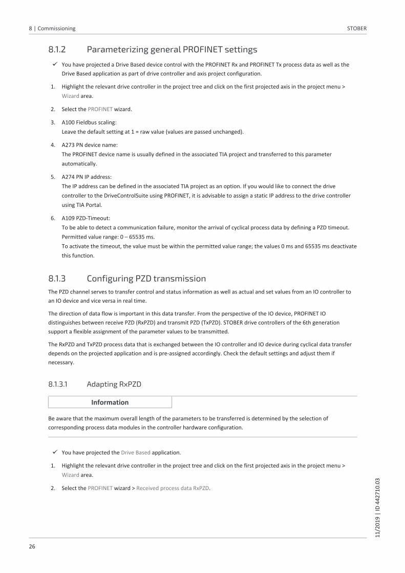
8.1.2 Parameterizing general PROFINET settings
ü You have projected a Drive Based device control with the PROFINET Rx and PROFINET Tx process data as well as theDrive Based application as part of drive controller and axis project configuration.
1. Highlight the relevant drive controller in the project tree and click on the first projected axis in the project menu >Wizard area.
2. Select the PROFINET wizard.
3. A100 Fieldbus scaling:Leave the default setting at 1 = raw value (values are passed unchanged).
4. A273 PN device name:The PROFINET device name is usually defined in the associated TIA project and transferred to this parameterautomatically.
5. A274 PN IP address:The IP address can be defined in the associated TIA project as an option. If you would like to connect the drivecontroller to the DriveControlSuite using PROFINET, it is advisable to assign a static IP address to the drive controllerusing TIA Portal.
6. A109 PZD-Timeout:To be able to detect a communication failure, monitor the arrival of cyclical process data by defining a PZD timeout.Permitted value range: 0 – 65535 ms. To activate the timeout, the value must be within the permitted value range; the values 0 ms and 65535 ms deactivatethis function.
8.1.3 Configuring PZD transmissionThe PZD channel serves to transfer control and status information as well as actual and set values from an IO controller toan IO device and vice versa in real time.
The direction of data flow is important in this data transfer. From the perspective of the IO device, PROFINET IOdistinguishes between receive PZD (RxPZD) and transmit PZD (TxPZD). STOBER drive controllers of the 6th generationsupport a flexible assignment of the parameter values to be transmitted.
The RxPZD and TxPZD process data that is exchanged between the IO controller and IO device during cyclical data transferdepends on the projected application and is pre-assigned accordingly. Check the default settings and adjust them ifnecessary.
8.1.3.1 Adapting RxPZD
Information
Be aware that the maximum overall length of the parameters to be transferred is determined by the selection ofcorresponding process data modules in the controller hardware configuration.
ü You have projected the Drive Based application.
1. Highlight the relevant drive controller in the project tree and click on the first projected axis in the project menu >Wizard area.
2. Select the PROFINET wizard > Received process data RxPZD.

STOBER 8 | Commissioning11
/201
9 |
ID 4
4271
0.03
27
3. Check the default settings and adapt the process data to be transferred to your requirements if necessary.A90[0] – A90[5], A91[0] – A91[5], A92[0] – A92[5]: Parameters whose values are received by the drive controller from the controller. The position provides informationabout the associated receiving sequence.
4. Resulting data length: Overall length of the data to be transmitted. This may not exceed the value 1 stored in the controller. If necessary,change the type or number of process data modules to be transmitted in the controller hardware configuration.
8.1.3.2 Adapting TxPZD
Information
Be aware that the maximum overall length of the parameters to be transferred is determined by the selection ofcorresponding process data modules in the controller hardware configuration.
ü You have projected the Drive Based application.
1. Highlight the relevant drive controller in the project tree and click on the first projected axis in the project menu >Wizard area.
2. Select the PROFINET wizard > Transmitted process data TxPZD.
3. Check the default settings and adapt the process data to be transferred to your requirements if necessary.A94[0] – A94[5], A95[0] – A95[5], A96[0] – A96[5]: Parameters whose values are received by the drive controller from the controller. The position provides informationabout the associated receiving sequence.
4. Resulting data length: Overall length of the data to be transmitted. This may not exceed the value 2 stored in the controller. If necessary,change the type or number of parameter values to be transmitted in the controller hardware configuration.
1 Max. 72 bytes/36 words2 Max. 72 bytes/36 words

8 | Commissioning STOBER
28
11/2
019
| ID
442
710.
03
8.1.4 Transmitting and saving the configurationIn order to transmit and save the configuration to one or more drive controllers, your PC must be located in the samenetwork with the respective devices.
Transmitting the configuration
ü The drive controllers are ready for operation.
1. In the project tree, highlight the module under which you have recorded your drive controllers and click Assignmentand live firmware update in the project menu.
ð The Add a connection window opens. All drive controllers found via IPv4 limited broadcast are displayed.
2. Direct connection tab > IP address column:Activate the IP address in question or activate all listed using the context menu. Confirm your selection with OK.
ð The Assignment and live firmware update window opens. All drive controllers connected through the previouslyselected IP addresses are displayed.
3. Select the drive controller to which you would like to transfer the configuration. Change the selection of transfer typefrom Read to Send.
4. Change the selection Create new drive controller:Select the configuration that you would like to transfer to the drive controller.
5. Repeat steps 3 and 4 for all other drive controllers to which you would like to transfer your configuration.
6. Online tab:Click on Establish online connections.
ð The configurations are transferred to the drive controllers.
Information
During the search, all drive controllers within the broadcast domain are found via IPv4 limited broadcast.
Prerequisites for finding a drive controller in the network:
▪ Network supports IPv4 limited broadcast
▪ All drive controllers are in the same subnet (broadcast domain)
STOBER 8 | Commissioning11
/201
9 |
ID 4
4271
0.03
29
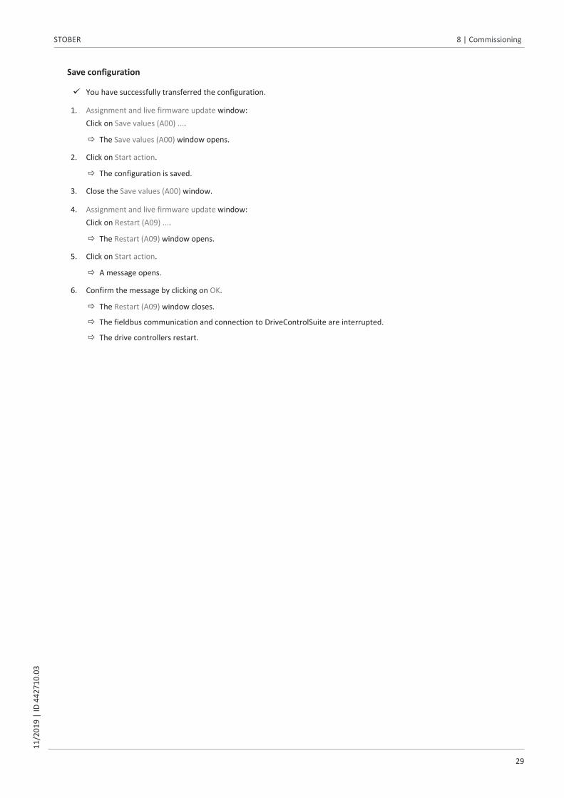
Save configuration
ü You have successfully transferred the configuration.
1. Assignment and live firmware update window:Click on Save values (A00) ....
ð The Save values (A00) window opens.
2. Click on Start action.
ð The configuration is saved.
3. Close the Save values (A00) window.
4. Assignment and live firmware update window: Click on Restart (A09) ....
ð The Restart (A09) window opens.
5. Click on Start action.
ð A message opens.
6. Confirm the message by clicking on OK.
ð The Restart (A09) window closes.
ð The fieldbus communication and connection to DriveControlSuite are interrupted.
ð The drive controllers restart.

8 | Commissioning STOBER
30
11/2
019
| ID
442
710.
03
8.2 TIA Portal: Setting up a PROFINET networkA PROFINET IO system generally consists of a PROFINET IO controller and the PROFINET IO devices assigned to it.
The Siemens TIA Portal gives you the option to map your actual PROFINET IO hardware environment, assign addresses to alldevices, parameterize the IO devices and configure the data exchange.
Be aware that all PROFINET system nodes must be networked before configuring the project in TIA Portal. You have alsoprojected all IO devices in advance using DriveControlSuite and transmitted the project configuration to the drivecontrollers.
Information
Always perform the steps included in the following chapters in the specified order!
Some parameters of the DriveControlSuite are interdependent and do not become accessible to you until you have firstconfigured certain settings. Follow the steps in the specified sequence so that you can finish the parameterizationcompletely.
8.2.1 Checking network addressesCheck whether the network addresses of the IO controller and IO supervisor are compatible before starting your projectconfiguration. To be able to set up a connection, both nodes must belong to the same subnet.
Reading out the IP address and subnet mask of the IO controller
1. Start TIA Portal and select Online & diagnostics > Accessible devices.
ð The Accessible devices window opens.
2. Type of the PG/PC interface:Select PN/IE.
3. PG/PC interface:Select the network connection you are using.
4. Click on Start search.
ð If it was possible to establish an online connection, all network nodes of your PROFINET system along with aspecification of the respective device type as well as the associated IP and MAC address are listed.
Reading out the IP address and subnet mask of the IO supervisor
1. IO supervisor: In your MS Windows system environment, click on the Control Panel > Network and Sharing Center >View your active networks area.
2. Access type/Connections:Click on the LAN connection in question.
ð The Local Area Connection Status window opens.
3. General tab > Connection area:Call up the network connection details via Details.
4. Compare the specified IP address and subnet mask of the IO supervisor with that of the IO controller. Both nodesmust belong to the same subnet.

STOBER 8 | Commissioning11
/201
9 |
ID 4
4271
0.03
31
8.2.2 Installing the GSD fileThe functions and properties of the STOBER drive controllers are described in the form of various objects and collected in ageneral station description file. In order to map and configure the drive controllers in the network, integrate the STOBER-specific GSD file into the hardware catalog of your TIA project.
ü You have downloaded the GSD file from the STOBER download area and saved it locally.
1. Start TIA Portal, create a project and save it. Open the TIA project view.
2. Select Options > Manage general station description files (GSD).
ð The Manage general station description files window opens.
3. Navigate to the directory that contains the STOBER-specific GSD file and click on OK.
ð The GSD file is imported.
4. Mark the file and click on Install.
ð The GSD file is installed; the drive controller is integrated into the hardware catalog as a new IO device.
8.2.3 Mapping the PROFINET IO systemMap the IO controller of your PROFINET IO system and all drive controllers, i.e. IO devices in a TIA project, by selecting thecorresponding hardware modules and incorporating them into the project.
Information
Be aware that you can only connect the IO controller and IO device logically in the TIA network view.
Incorporating the IO controller
ü You have created a new project in TIA and installed the STOBER-specific GSD. You are in the TIA network view; thehardware catalog is open.
1. Hardware catalog: Select Controller > SIMATIC S7-1500 > CPU and open the folder of the CPU type that your controller belongs to (e.g.CPU 1513-1 PN).
2. Drag and drop the desired CPU into the network view.
ð The IO controller is incorporated into your project.
Incorporating IO devices
1. Hardware catalog: Select Other field devices > PROFINET IO > Drives > STOBER ANTRIEBSTECHNIK GmbH & Co. KG > STOBERANTRIEBSTECHNIK > STOBER 6th generation drives > PN6A.
2. Drag and drop the corresponding module into the network view.
ð The IO device is incorporated into your project.
3. Repeat steps 1 and 2 for all IO devices that are in your physical PROFINET IO system.
Connecting IO controller and IO devices "logically"
1. Connect the projected devices logically with one another by clicking on the port of the IO controller and dragging aconnection to the port of the first IO device while holding the mouse button.
2. Network the ports of all IO devices as described in step 1.
ð Your PROFINET IO system is mapped in your TIA project.

8 | Commissioning STOBER
32
11/2
019
| ID
442
710.
03
8.2.4 Configuring the IO controllerAs needed, you can change the pre-configured IP address and subnet address of the IO controller.
ü You are in the TIA network view.
1. Double-click on the IO controller of your IO system.
ð This switches you to the respective device view.
2. Select General tab > General > PROFINET interface > Ethernet addresses in the device properties.
3. IP protocol area:Set IP address in the project: Activate this option if it is not active by default and change the IP and subnet addressesof the IO controller.
ð IP and subnet address are reconfigured.
8.2.5 Configuring IO devicesIn this step, specify the data volume to be transmitted for every IO device of your PROFINET IO system and name the IOdevices according to PROFINET naming conventions.
If the respective IP addresses of the IO devices should not be assigned automatically by the IO controller, modify the defaultaddresses. You also have the option to configure the monitoring of the IO data exchange.
Defining transmission volumes
ü You are in the TIA network view. The hardware catalog is open.
1. Double-click on an IO device in your IO system.
ð This switches you to the respective device view.
2. Hardware catalog: Select Catalog > Module.
ð There are two categories available that determine the data volumes generally to be transmitted.
3. Select a module with a data volume that corresponds to your process data map in the drive controller. Mark thismodule and drag and drop it onto the Device overview tab > Line/slot 1 and slot 2.
ð The input and output addresses of the IO device are generated automatically.
Assigning device names
1. Double-click on an IO device in your IO system.
ð This switches you to the respective device view.
2. Device view: Double-click on the IO device graphic.
3. Device properties: Select the General tab.
4. General area:Name: Name the IO device according to PROFINET naming conventions.
5. Device view: Mark the IO device in question and select Assign device name using the context menu.
ð The Assign PROFINET device name window opens.

STOBER 8 | Commissioning11
/201
9 |
ID 4
4271
0.03
33
6. Select Update list.
ð All IO devices of the defined subnet are listed along with a specification of the respective device type and theassociated IP and MAC address.
7. Mark the IO device that you would like to name and click on Assign name.You can test your selection beforehand by verifying the selected drive controller either with Flash LED or using its ownMAC address (read the parameter A279 PN MAC addresses).
ð The device name is assigned to the selected IO device.
Configuring the IO cycle
1. Double-click on an IO device in your IO system.
ð This switches you to the respective device view.
2. Advanced options area > Real time settings > IO cycle > Update time:Automatic: Activate this option if the period during which the controller and device exchange IO data is to becalculated automatically.Can be set: If you would like to calculate the update time yourself, activate this option and enter the desired time(unit: milliseconds).Adapt update time when send clock changes: Activate this option if the ratio between the update time andtransmission cycle is to remain constant.
3. Advanced options area > Real time settings > IO cycle > Watchdog time:Accepted update cycles without IO data: Check the default settings and change the number of permitted cycleswithout a data transfer if necessary.Watchdog time: The watchdog time is calculated automatically based on the permitted cycles; it may not exceed 1.92seconds.
Information
Define the associated transmission volume for every IO device in your PROFINET IO system; assign a device name for eachand configure a corresponding IO cycle.

8 | Commissioning STOBER
34
11/2
019
| ID
442
710.
03
8.2.6 Transmitting a project configurationTransmit the full project configuration to your IO controller.
ü You have mapped and parameterized all nodes of your physical PROFINET IO system in your TIA project.
1. Project tree > Devices tab: Mark the folder with the IO controller in question.
2. Select Online > Download to device in the menu bar.
ð The Extended download to device window opens.
3. Compatible devices in target subnet area: Click on Start search.
ð All IO controllers of the defined subnet are listed.
4. Mark the IO controller in which you would like to save the project configuration and click Load. If multiple IO controllers are in your subnet, you can test your selection beforehand by verifying the selectedcontroller using Flash LED.
ð The project configuration is transferred to the selected IO controller.
8.2.7 Testing communicationCheck for error-free communication between the IO controller and IO devices.
ü You have transferred the project configuration to the IO controller.
1. Project tree > Devices tab: Open the folder of the controller in question > Online & diagnostics > Online access.
ð This switches you to the respective device view.
2. Verify the active IO controller and click on Go online.
ð An online connection to the selected IO controller is established.
3. Click on Diagnostics > Diagnostics buffer.
4. Events area: The diagnostics buffer is part of the IO controller's system memory. Possible error messages are output here. If anerror message is not present, communication in your PROFINET IO system is free of errors.
ð The connection between IO controller and IO devices is projected and data exchange is possible.

STOBER 8 | Commissioning11
/201
9 |
ID 4
4271
0.03
35
8.2.8 Programming acyclical communication servicesTo be able to transfer parameters acyclically, PROFINET provides the Read record and Write record services.
The services are controlled using SIMATIC function blocks RDREC and WRREC. You can either integrate this into the PLCprogram yourself or load and parameterize one of the example projects provided for download by STOBER in the TIA Portal.
Information
In the context of the latter, observe the documentation belonging to the example projects.
1. To get the latest project version, switch to the download area on the STOBER website http://www.stoeber.de/en/downloads/ and enter the term TIA Portal V14 in the search field.
ð The TIA Portal V14 project (examples for generation 6) is displayed in the result list.
2. Start the download and save the TIA _Portal_V14_de.zip file to your PC.
3. Unpack the ZIP file.
ð The ZIP file contains two ZAP14 files (SAT_DriveBased_V14_1200 and SAT_DriveBased_V14_1500) for Siemenscontrollers SIMATIC S7-1200 and SIMATIC S7-1500.
4. TIA Portal: Select Project > Retrieve and navigate to the directory where you saved the example projects.
5. Open the ZAP14 file SAT_DriveBased_V14_1500.
ð The example project is loaded in the TIA project view.
6. Project tree > Devices tab: Open the folder of the IO controller > Program blocks
7. G6_Read_Acyclic and G6_Write_Acyclic function blocks:Parameterize the blocks as described in the documentation of the example program.
Information
Note that only one acyclic access per device may be active at the same time! When using the services in combination withinternal function blocks, access coordination must be resolved in the application.
In the example project provided by STOBER, the xLockAcyclic bit coordinates simultaneous acyclic access to a drivecontroller. The bit locks the communication for other blocks. Every block that acyclically accesses a drive controller locksaccess using the xLockAcyclic bit and enables it again by resetting the bit as soon as the data exchange has ended.
9 | Monitoring and diagnostics STOBER
36
11/2
019
| ID
442
710.
03
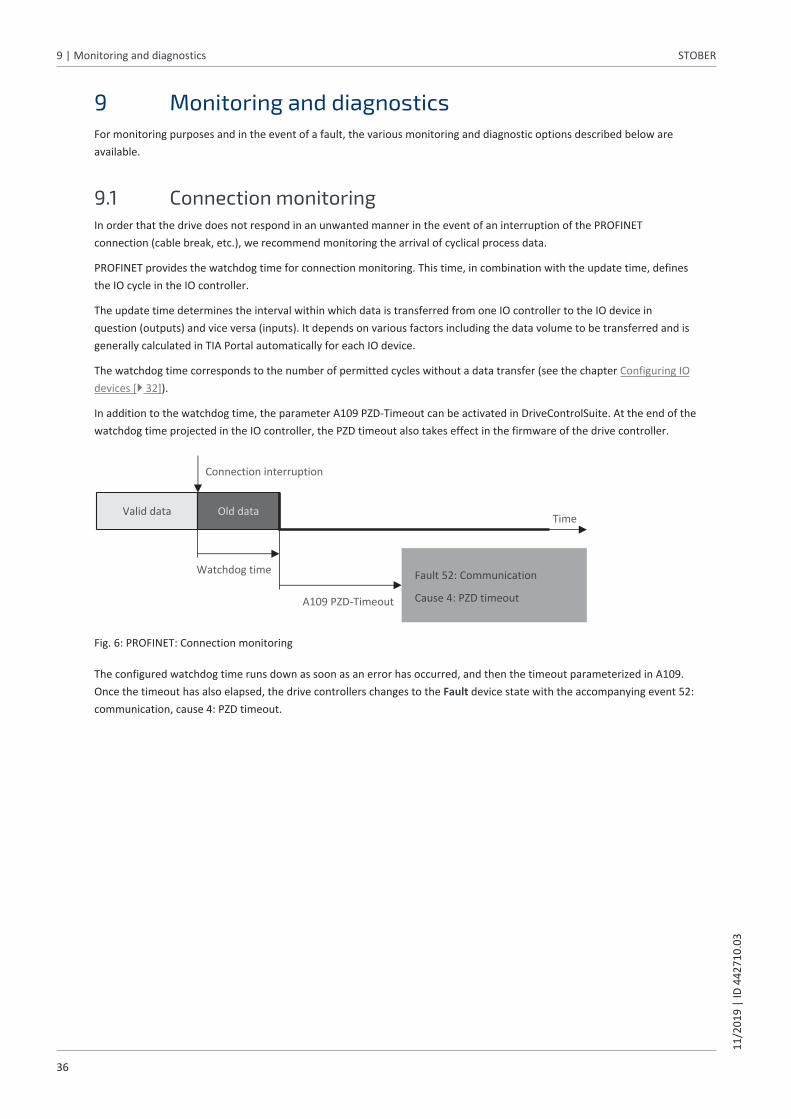
9 Monitoring and diagnosticsFor monitoring purposes and in the event of a fault, the various monitoring and diagnostic options described below areavailable.
9.1 Connection monitoringIn order that the drive does not respond in an unwanted manner in the event of an interruption of the PROFINETconnection (cable break, etc.), we recommend monitoring the arrival of cyclical process data.
PROFINET provides the watchdog time for connection monitoring. This time, in combination with the update time, definesthe IO cycle in the IO controller.
The update time determines the interval within which data is transferred from one IO controller to the IO device inquestion (outputs) and vice versa (inputs). It depends on various factors including the data volume to be transferred and isgenerally calculated in TIA Portal automatically for each IO device.
The watchdog time corresponds to the number of permitted cycles without a data transfer (see the chapter Configuring IOdevices [} 32]).
In addition to the watchdog time, the parameter A109 PZD-Timeout can be activated in DriveControlSuite. At the end of thewatchdog time projected in the IO controller, the PZD timeout also takes effect in the firmware of the drive controller.
Fault 52: Communication
Cause 4: PZD timeout A109 PZD-Timeout
Time
Watchdog time
Connection interruption
Old dataValid data
A109 PZD-Timeout
Fig. 6: PROFINET: Connection monitoring
The configured watchdog time runs down as soon as an error has occurred, and then the timeout parameterized in A109.Once the timeout has also elapsed, the drive controllers changes to the Fault device state with the accompanying event 52:communication, cause 4: PZD timeout.

STOBER 9 | Monitoring and diagnostics11
/201
9 |
ID 4
4271
0.03
37
9.2 LED displaySTOBER drive controllers feature diagnostic LEDs that visualize the state of fieldbus communication and the states of thephysical connection.
9.2.1 PROFINET stateThere are 2 LEDs on the top of the drive controller that provide information about the connection between the IOcontroller and device and about the state of the data exchange. This information can also be read out in parameter A271PN state.
X200
BF-R
un
21
Fig. 7: LEDs for the PROFINET state
1 Red: BF (bus error)
2 Green: Run
Red LED Conduct Description
Off No error
Rapid flashing Data exchange with IO controller notactive
On No network connection
Tab. 4: Meaning of the red LED (BF)
Green LED Conduct Description
Off No connection
Flash Connection is set up to IO controller
Flash, inverse IO controller activates DHCP signalservice
Flashing Existing connection to IO controller;data exchange expected
On Existing connection to IO controller
Tab. 5: Meaning of the green LED (Run)

9 | Monitoring and diagnostics STOBER
38
11/2
019
| ID
442
710.
03
9.2.2 PROFINET network connectionThe Act. and Link LEDs at X200 and X201 on the top of the device indicate the state of the PROFINET network connection.
X200
21 43
X201
BF-R
un
Link Act Link Act
Fig. 8: LEDs for the state of the PROFINET network connection
1 Green: Link at X201
2 Yellow: Activity at X201
3 Green: Link at X200
4 Yellow: Activity at X200
Green LED Behavior Description
Off No network connection
On Network connection exists
Tab. 6: Meaning of the green LEDs (Link)
Yellow LED Behavior Description
Off No data exchange
Flashing Active data exchange with IO controller
Tab. 7: Meaning of the yellow LEDs (Act.)

STOBER 9 | Monitoring and diagnostics11
/201
9 |
ID 4
4271
0.03
39
9.3 EventsThe drive controller has a self-monitoring system that uses test rules to protect the drive system from damage. Violatingthe test rules triggers a corresponding event. There is no possible way for you as the user to intervene in some events, suchas the Short/ground event. In others, you can influence the effects and responses.
Possible effects include:
§ Message: Information that can be evaluated by the controller
§ Warning: Information that can be evaluated by the controller and becomes a fault after a defined time span haselapsed without the cause being resolved
§ Fault: Immediate drive controller response; the power unit is disabled and axis movement is no longer controlled bythe drive controller or the axis is brought to a standstill by a quick stop or emergency braking
ATTENTION!
Damage to property due to interruption of a quick stop or emergency braking
If, when executing a quick stop or emergency braking, another fault occurs or a safety function is activated, the quick stopor emergency braking is interrupted. In this case, the machine can be damaged by the uncontrolled axis movement.
Events, their causes and suitable measures are listed below. If the cause of the error is corrected, you can usuallyacknowledge the error immediately. If the drive controller has to be restarted instead, a corresponding note can be foundin the measures.
9.3.1 Event 52: CommunicationThe drive controller has a fault if A29 = 0: Inactive:
§ The power unit is disabled and axis movement is no longer controlled by the drive controller
§ The brakes are applied in the event of an inactive release override (F06)
The drive controller is interrupted with a quick stop if A29 = 1: Active:
§ The axis is stopped by a quick stop; meanwhile, the brakes remain released
§ At the end of the quick stop, the power unit is disabled and the axis movement is no longer controlled by the drivecontroller; the brakes are applied in the event of an inactive release override (F06)
Cause Check and action
4: PZD-Timeout Missing process data Check the IO cycle time in the PROFINET IOcontroller and the timeout time in the drivecontroller and correct them if necessary (A109)
14: PZD parameter figure faulty Missing mapping Check the mapping for unmappableparameters and correct them if necessary
Tab. 8: Event 52 – Causes and actions

9 | Monitoring and diagnostics STOBER
40
11/2
019
| ID
442
710.
03
9.4 ParametersThe following diagnostic parameters are available for you in PROFINET communication in combination with drive controllersof the SD6 series.
9.4.1 A270 | X20x state | V0State of the network connection (fieldbus).
§ [0]: X200
• 0: Error
• 1: No connectionNo network cable plugged in
• 2: 10 MBit/sConnection active; transfer rate of 10 Mbps
• 3: 100 MBit/sConnection active; transfer rate of 100 Mbps, half-duplex
• 4: Link OKConnection active; transfer rate of 100 Mbps, full-duplex
§ [1]: X201See [0]: X200
9.4.2 A271 | PN state | V0State of the drive controller in the PROFINET network.
§ 0: offlineHardware not ready for use
§ 1: step 1Hardware ready for use; no connection to the IO controller
§ 2: step 2IP address received; connection to the IO controller is set up
§ 3: phase 1drive controller is configured by the IO controller
§ 4: phase 2Device start-up of IO controller and drive controller completed; process data communication is started
§ 5: cyclic data exchangeProcess data communication active
9.4.3 A272 | PN module/submodule | V1Module configuration of the drive controller in the PROFINET network (source: IO controller; format: XXX / YYY / ZZZ; XXX =module ID, YYY = RxPZD data length in bytes, ZZZ = TxPZD data length in bytes).
9.4.4 A273 | PN device name | V0Device name of the drive controller in the PROFINET network (source: IO controller).
§ [0] – [2]: Current device name; parts 1 – 3
§ [3] – [5]: Device name after the next fieldbus restart; parts 1 – 3

STOBER 9 | Monitoring and diagnostics11
/201
9 |
ID 4
4271
0.03
41
9.4.5 A274 | PN IP address | V0IP address of the drive controller in the PROFINET network (source: IO controller).
§ [0]: Current IP address
§ [1]: IP address after the next fieldbus restart
9.4.6 A275 | PN subnet mask | V0Subnet mask of the drive controller in the PROFINET network (source: IO controller).
§ [0]: Current subnet mask
§ [1]: Subnet mask after the next fieldbus restart
9.4.7 A276 | PN gateway | V0Gateway address of the drive controller in the PROFINET network (source: IO controller).
§ [0]: Current gateway address
§ [1]: Gateway address after the next fieldbus restart
9.4.8 A279 | PN MAC addresses | V0MAC addresses of the drive controller in the PROFINET network.
§ [0]: PROFINET device
§ [1]: X200
§ [2]: X201

10 | More on PROFINET? STOBER
42
11/2
019
| ID
442
710.
03
10 More on PROFINET?The following chapters summarize the key terms, services and relationships relating to PROFINET.
10.1 PROFINETPROFINET (process field network) is the open industrial Ethernet standard for automation from Siemens, developed incollaboration with the PROFIBUS-Nutzerorganisation e. V. PROFINET is standardized in IEC 61158 and IEC 61784.
PROFINET is based on Ethernet TCP/IP and is primarily used in cases where fast data communication over Ethernetnetworks combined with industrial IT functions are needed.
PROFINET IO
PROFINET IO was designed in addition to PROFINET CBA as a technological variant for quick data exchange between acontroller and decentralized field devices (decentral peripherals, DP). PROFINET IO is based on PROFIBUS DP and uses FastEthernet as the means of transmission. Process data (PZD), data for parameterization (parameter channel data), data fordiagnostic purposes, alarms and IT applications are all transferred—over a single network.
PROFINET transmits data with and without a real-time request, while process data and alarms are exclusively transferredusing the real-time communication. PROFINET IO provides two versions in order to scale this optimally: PROFINET IO-RT for unsynchronized communication and PROFINET IO-IRT for cycle-synchronized real-time communication.
STOBER drive controllers of the 6th generation support PROFINET IO-RT.
PROFINET follows the provider-consumer model where communication partners are on equal footing. Data can be sentwithout a request from another network node. Normally, in the case of a data exchange, a controller (IO controller) reads inthe signals from the field devices, i.e. the IO devices, processes them and provides them back to the devices.
10.2 Device classesPROFINET IO classifies network nodes into the following device classes based on their tasks.
IO supervisor
An IO supervisor is typically a piece of engineering and diagnostics software that can access all process and configurationdata and process alarms or diagnostic messages. The supervisor is normally only integrated into the network on a temporary basis.
IO controller
An IO controller controls data communication, i.e. it receives process data and event-controlled messages and processesthem. A programmable logic controller (PLC, e.g. SIMATIC S7-1500) normally handles the role of the IO controller.
IO device
An IO device is typically a decentrally located I/O field device (e.g. a drive controller) that is assigned to at least one IOcontroller.
An IO device transmits process and configuration data as well as alarms. It normally consists of modules that contain theindividual input and output signals of the respective process.

STOBER 10 | More on PROFINET?11
/201
9 |
ID 4
4271
0.03
43
10.3 CommunicationAn IO controller controls and regulates communication with IO devices in the PROFINET network. In the process, thecontroller transmits cyclical process data (PZD), such as control information, to the devices and receives current statesignals from them.
In addition, IO controllers and IO devices acyclically exchange data that is not time-critical, such as configuration parametervalues or one-time events, using parameter channel data.
Both communication services run in parallel, with transmission of cyclical PZD having higher priority. In each cyclicalexchange of data, an acyclical frame is injected as needed.
10.3.1 Cyclical communication: Process dataProcess data (PZD) objects are normally data that is required for controlling and observing the ongoing process, such astarget positions, travel velocities or acceleration information. It is generally used for data exchange in real time. It also gives you simultaneous access to multiple drive parameters.Process data is exchanged quickly and cyclically with a high priority over the RT real-time channel.
For PROFINET IO, the cyclical data traffic relies directly on the MAC address of a device and does not contain any IPaddresses. This keeps the overall length of a data packet relatively small. The direction of data flow is of critical importance in this data transfer. From the perspective of the respective nodes, adistinction is made between receive PZD (RxPZD) and transmit PZD (TxPZD).
The specific communication elements that are sent and received in specific PZD can be freely selected. The length andstructure of process data are defined as part of project configuration by means of the process data modules (see thechapter Process data modules [} 54]). Currently, 18 parameter values with a maximum total length of 72 bytes (36 words) can be exchanged between the IOcontroller and IO device per drive controller.
10.3.2 Acyclical communication: Parameter channel data
Information
If you use the example project provided by STOBER for programming acyclical communication services, this chapter is notrelevant in practice.
The parameter channel is used to transfer data that is not time-critical. Parameter channel data enables read and writeaccess to the configuration parameters of an IO device and transfers one-time events.
Parameter channel data is transmitted acyclically in ongoing cyclical PROFINET operation, without impairing PZDcommunication. This requires drive-specific acyclical communication services. You can either program them based on the RDREC and WRRECSIMATIC system function blocks (see the following chapters) or load a STOBER-specific example project specifically tailoredto the STOBER drive controllers of the 6th generation from the download area in your TIA Portal and configure theparameters appropriately for your system environment.
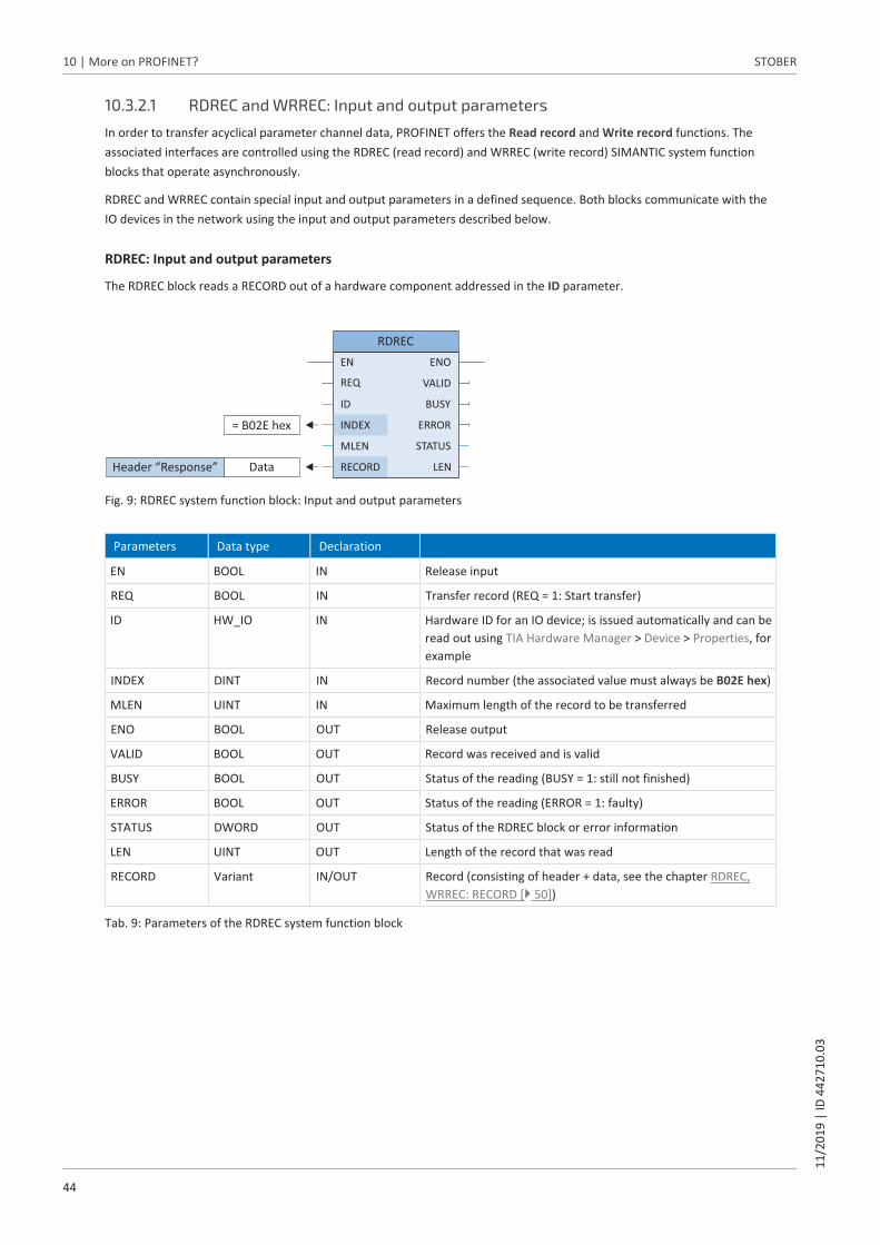
10 | More on PROFINET? STOBER
44
11/2
019
| ID
442
710.
03
10.3.2.1 RDREC and WRREC: Input and output parameters
In order to transfer acyclical parameter channel data, PROFINET offers the Read record and Write record functions. Theassociated interfaces are controlled using the RDREC (read record) and WRREC (write record) SIMANTIC system functionblocks that operate asynchronously.
RDREC and WRREC contain special input and output parameters in a defined sequence. Both blocks communicate with theIO devices in the network using the input and output parameters described below.
RDREC: Input and output parameters
The RDREC block reads a RECORD out of a hardware component addressed in the ID parameter.
REQ
STATUS
ID
LEN
BUSY
ERRORINDEX
MLEN
VALID
= B02E hex
RECORD
EN ENO
RDREC
DataHeader “Response”
Fig. 9: RDREC system function block: Input and output parameters
Parameters Data type Declaration
EN BOOL IN Release input
REQ BOOL IN Transfer record (REQ = 1: Start transfer)
ID HW_IO IN Hardware ID for an IO device; is issued automatically and can beread out using TIA Hardware Manager > Device > Properties, forexample
INDEX DINT IN Record number (the associated value must always be B02E hex)
MLEN UINT IN Maximum length of the record to be transferred
ENO BOOL OUT Release output
VALID BOOL OUT Record was received and is valid
BUSY BOOL OUT Status of the reading (BUSY = 1: still not finished)
ERROR BOOL OUT Status of the reading (ERROR = 1: faulty)
STATUS DWORD OUT Status of the RDREC block or error information
LEN UINT OUT Length of the record that was read
RECORD Variant IN/OUT Record (consisting of header + data, see the chapter RDREC,WRREC: RECORD [} 50])
Tab. 9: Parameters of the RDREC system function block

STOBER 10 | More on PROFINET?11
/201
9 |
ID 4
4271
0.03
45
WRREC: Input and output parameters
The WRREC system function block transfers the RECORD to a hardware component addressed in the ID parameter.
REQ
ID
STATUS
BUSY
ERRORINDEX
DONE
RECORD
EN ENO
WRREC
DataHeader “Request”
= B02E hex
Fig. 10: WRREC system function block: Input and output parameters
Parameters Data type Declaration
EN BOOL IN Release input
REQ BOOL IN Transfer record (REQ = 1: Start transfer)
ID HW_IO IN Hardware ID for an IO device; is issued automatically and can beread out using TIA Hardware Manager > Device > Properties, forexample
INDEX DINT IN Record number (the associated value must always be B02E hex)
ENO BOOL OUT Release output
DONE BOOL OUT Status of the communication: Record was transferred
BUSY BOOL OUT Status of the writing (BUSY = 1: still not finished)
ERROR BOOL OUT Status of the writing (ERROR = 1: faulty)
STATUS DWORD OUT Status of the WRREC block or error information
RECORD Variant IN/OUT Record (consisting of header + data, see the chapter RDREC,WRREC: RECORD [} 50])
Tab. 10: Parameters of the WRREC system function block

10 | More on PROFINET? STOBER
46
11/2
019
| ID
442
710.
03
10.3.2.2 RDREC and WRREC: Acyclical communication flow
The following diagrams clarify the communication flow of the RDREC and WRREC system function blocks.
Read record flow
1. WRREC [Header Request (Request_ID = 0x01)]
2. RDREC
3. RDREC [Header Response (Response_ID = 0x01) + Data]
3. RDREC [Header Response (Response_ID = 0x81) + Data]
Eitherparameter value
orerror
Preparation of parameter value
IO controller IO device
Fig. 11: RDREC flow
During RDREC, be aware that each parameter service begins with a read record request and ends with a read recordresponse.
Write record flow
1. WRREC [Header Request (Request_ID = 0x02) + Data ]
2. RDREC
3. RDREC [Header Response (Response_ID = 0x02) + Data]
3. RDREC [Header Response (Response_ID = 0x02) + Data]
EitherOK
orerror
Internal processing
IO controller IO device
Fig. 12: WRREC flow

STOBER 10 | More on PROFINET?11
/201
9 |
ID 4
4271
0.03
47
10.4 Communication protocols
...
HTTP SNMP
DHCP Standard data Real-timedata
TCP/UDP
IP
Real-timeprotocol
Fast Ethernet
PROFINET applicationsIT applications
Fig. 13: PROFINET communication protocols
One protocol optimized for fast Ethernet is suitable for real-time communication: the real-time protocol. It allows for a high-performance transfer of cyclical real-time data and event-driven messages.
Standard PROFINET data without a real-time request, such as parameter values or diagnostic data, is usually transferredusing the TCP/IP or UDP/IP protocols. For typical IT applications such as the transfer of websites, e-mails, etc., PROFINETrelies on standard IT protocols such as HTTP or SNMP.
10.5 Ethernet network addressingAll PROFINET IO nodes are based on the Industrial Ethernet Standard, meaning that the assignment of the followingaddresses and names is important to be able to communicate with IO devices in the PROFINET IO system.
10.5.1 MAC addressEach network interface of a device in an Ethernet network requires its own address—a MAC address. The MAC address isused as a source and destination address for cyclical data exchange.
A MAC address consists of a fixed and a variable part. The fixed part identifies the manufacturer (3 bytes) and the variablepart distinguishes the individual Ethernet nodes and must be globally unique (also 3 bytes). A MAC address can onlycommunicate between two nodes of the same subnet.
The MAC addresses of the interfaces are issued by STOBER and cannot be changed.
Information
The MAC address range of the STOBER hardware is: 00:11:39:00:00:00 – 00:11:39:FF:FF:FF
You can read out the MAC address of the PROFINET interface using the A279 PN MAC addresses parameter.

10 | More on PROFINET? STOBER
48
11/2
019
| ID
442
710.
03
10.5.2 IP addressEach PROFINET IO node has to support various Ethernet-based protocols, at least TCP/IP and UDP/IP.
All data packets sent over the IP protocol contain the respective recipient and sender addresses. Consequently, eachPROFINET node needs a unique IP address to be able to receive communication. The IP protocol is hardware-independent; unlike the fixed MAC address, the IP address is explicitly assigned to each IOdevice.
The IP address is for acyclical data exchange, e.g. transferring the project configuration to the IO controller, configuring theIO devices and reading out device and diagnostic information.
An IPv4 address consists of 4 decimal numbers from the value range 0 – 255 separated by a decimal.
Read out the IP address of a drive controller using the A274 PN IP address parameter.
10.5.3 Subnet maskAn IP address always consists of a network ID (for identifying the network) and a host ID (for identifying the node). A subnetmask defines which parts of the IP address are assigned to the network ID. It has the structure of the IP address but onlymarks the network ID.
Read out the subnet mask using the A275 PN subnet mask parameter.
10.5.4 Subnets and gatewaysThe IP addresses of a network are usually subdivided into subnets. The purpose of subnets is to provide autonomousnetworks with an address range. All PROFINET IO nodes connected by switches are in a subnet, meaning that theycommunicate over a direct path. All nodes of a subnet have the same subnet mask.
Gateways are components of a subnet and are responsible for forwarding subnet-specific network queries to othersubnets.
Information
Be aware that real-time communication is only possible within a subnet due to addressing with MAC addresses. It is notpossible to use routers for real-time communication via PROFINET.
10.5.5 MAC and IP addressing using device namesTo be able to provide unique identification of an IO device in a PROFINET IO system, it must have a symbolic device namethat is unique in the system. It is assigned during the project planning phase in TIA Portal and then transferred to the IOdevices. The device name is used for parameterizing the individual IO devices during system start-up and assigning therespective MAC and IP addresses, the latter using DCP or DHCP.
Observe the following conventions when specifying device names:
§ The device name must be limited to a maximum of 240 characters. Letters, numbers, periods and dashes are permitted.
§ A name component, i.e. a character string between 2 periods, may be a maximum of 63 characters long.
§ Special characters like umlauts, brackets, question marks, slashes, spaces, etc. are not allowed.
§ The device name may not begin with numbers.
§ The device name may neither begin nor end with a minus sign (−) or a period (.).
§ The device name may not take the form n.n.n.n (n = 0 – 999).
§ The device name may not begin with the character sequence port-xyz- (x, y, z = 0 – 9).
§ Underscores (_) are not allowed.

STOBER 11 | Appendix11
/201
9 |
ID 4
4271
0.03
49
11 Appendix
11.1 Addressing parameters for RECORD recordTo be able to address a parameter via fieldbus, you need its Axis_number, Parameter_number and subindex. These arecalculated from the STOBER parameter coordinates (axis, group, line, element).
Basic information on the parameters can be found in the chapter Meaning of parameters [} 19].
11.1.1 Determining the Axis_numberThe Axis_number corresponds to the axis of the parameter.
11.1.2 Calculating the Parameter_number
Information
Parameter_numberNote that the Parameter_number in the RECORD record must be specified in hexadecimal form.
The Parameter_number is calculated from the group and line of the parameter according to the following formula:
Parameter_number decimal = 8192 + (number of the group × 512) + number of the line
Calculation example for parameter E200 (number of the group = 4 , number of the line = 200):Parameter_number E200 = 8192 + (4 × 512) + 200 = 10440 = 28C8 hex
Group Number Addressable parameters
A: Drive controller 0 A00 – A511
B: Motor 1 B00 – B511
C: Machine 2 C00 – C511
D: Target value 3 D00 – D511
E: Display 4 E00 – E511
F: Terminals 5 F00 – F511
G: Technology 6 G00 – G511
H: Encoder 7 H00 – H511
I: Motion 8 I00 – I511
J: Motion blocks 9 J00 – J511
K: Control panel 10 K00 – K511
M: Profile 12 M00 – M511
P: Customer-specific parameters 15 P00 – P511
Q: Customer-specific parameters,instance-dependent
16 Q00 – Q511
R: Production data 17 R00 – R511
S: Safety 18 S00 – S511
T: Scope 19 T00 – T511
U: Safety functions 20 U00 – U511
Z: Fault counter 25 Z00 – Z511
Tab. 11: Groups and parameters

11 | Appendix STOBER
50
11/2
019
| ID
442
710.
03
11.1.3 Determining the subindexThe subindex corresponds to the element of the array or structure parameter. The subindex of simple parameters is 0.
11.2 RDREC, WRREC: RECORD
11.2.1 RECORD request: Header structureParameter values are generally transferred using the RECORD header. For a record request, this consists of the followingelements in the specified sequence.
Element Data type Value, value range
Request_reference BYTE 0 hex – FF hex Freely selectable request number
Request_ID BYTE 1 hex Read request
2 hex Write request
All other values Reserved
Axis_number BYTE 0 – 3 Addressing the axis
Number_of_parameters BYTE 1 Number of parameters to be processed
All other values Reserved
Attribute BYTE 10 hex Access type: Value
80 hex Access type: Raw value
81 hex Access type: Integer
82 hex Access type: Floating point
Number_of_elements BYTE 1 – 32 hex 1 – 50 Parameters are to be written orread
Parameter_number WORD 2000 hex – 5FFF hex Group and line of a parameter
Subindex WORD 0 – 3E80 hex Element of a list and structureparameter; in single parameters, thevalue = 0
Format(Condition: Request_ID = 2 hex)
BYTE 8 hex Transfer format: FLOAT
41 hex Transfer format: BYTE
42 hex Transfer format: WORD
43 hex Transfer format: DWORD
1C hex, 1D hex, 1E hex Transfer format: STRING with 8, 16 or 80characters
Number_of_values(Condition: Request_ID = 2 hex)
BYTE 1 – 50 Number of values to be processed; value = 1 (in a simple parameter) orvalue = value of Number_of_elements; since a RECORD request may not exceeda length of 240 bytes, it is not alwayspossible – depending on the respectiveformat – to transfer max. 50 elements
1st value(Condition: Request_ID = 2 hex)
DINT 1st parameter value Value in a simple parameter
2nd value – 50th value(Condition: Request_ID = 2 hex)
DINT 1 – 32 hex Value = Value of Number_of_elements
Tab. 12: RECORD request: Header structure

STOBER 11 | Appendix11
/201
9 |
ID 4
4271
0.03
51
11.2.2 RECORD response: Header structureParameter values are generally transferred using the RECORD header. For a record response, it consists of the followingelements in the specified sequence.
Element Data type Value, value range
Response_reference BYTE 0 hex – FF hex Value = Request number of RECORDrequest
Response_ID BYTE 1 hex Positive answer to a read request
2 hex Positive answer to a write request
81 hex Negative answer to a read request
82 hex Negative answer to a write request
Axis_number BYTE 0 – 3 Addressing the axis
Number_of_parameters BYTE 1 Number of parameters to be processed
Format BYTE 8 hex Transfer format: FLOAT
41 hex Transfer format: BYTE
42 hex Transfer format: WORD
43 hex Transfer format: DWORD
1C hex, 1D hex, 1E hex Transfer format: STRING with 8, 16 or 80characters
44 hex Error in case of error
Number_of_values BYTE 1 Number of values to be processed
1st value or error code
DINT 1st parameter value Value in a simple parameter
WORD Error code in case of error (see tableError codes [} 52])
2nd value – 50th value DINT 1 – 32 hex Value = Value of Number_of_elements
Tab. 13: RECORD response: Header structure

11 | Appendix STOBER
52
11/2
019
| ID
442
710.
03
11.2.3 Error codesThe following table shows the possible error codes along with the coding of the cause of error.
Value
0 hex Parameter unfamiliar or configuration stopped
1 hex Access to read-only parameter
2 hex Access to parameter with value outside the limit
3 hex Access to unavailable subindex (array parameter)
B hex User level not reached
11 hex Parameter may not be changed in the current device state; deactivate release
14 hex Invalid value within maximum limits; only occurs in the case of selection parameters with a brokendefinition range
16 hex One or more incorrect values in the attribute, Number_of_elements, Parameter_number and subindexelements
17 hex Invalid format specification
18 hex Contrary value in the Number_of_elements and Number_of_values elements
21 hex Invalid Request_ID = Service not supported; applies to errors in the header of the request block
A5 hex Error cannot be specified in more detail
B0 hex Parameter service currently not possible or valid parameter description not present
B2 hex Unfamiliar parameter address (parameter or element does not exist)
B3 hex Read/write access not possible for specified parameter address
B9 hex Parameter service: Value in definition gap (observe ENUM list)
BA hex Parameter service: Clash with other values
C0 hex Parameter service: Error in pre-read function
C1 hex Parameter service: Error in post-write function; value has already been received
Tab. 14: RDREC, WRREC: Error codes

STOBER 11 | Appendix11
/201
9 |
ID 4
4271
0.03
53
11.2.4 Attribute and format elements: Possible combinationsThe attribute element describes the access to a parameter structure (e.g. to values, descriptive texts, etc.); the formatelement describes the transfer format of a parameter. The values of both elements can be combined as follows.
Attribute Format
FLOAT (8 hex)
BYTE (41 hex)
WORD (42 hex)
DWORD (43 hex)
STRING(1C hex, 1D hex,1E hex)
Value (10 hex)
Not permitted Not permitted Not permitted Scaled value for allparametersrepresented asinteger (4 bytes)
8, 16 or 80characters
Raw value (80 hex)
Unscaled rawvalue, specificallyfor FLOAT datatype (4 bytes)
Unscaled rawvalue, specificallyfor BOOL, WORD,I8 data types(1 byte)
Unscaled rawvalue, specificallyfor WORD, I16data types (2 bytes)
Unscaled rawvalue, specificallyfor DWORD, I32data types (4 bytes)
Not permitted
Integer (81 hex)
Not permitted Not permitted Not permitted Scaled value for allparametersrepresented asinteger (4 bytes)
Not permitted
Floating point (82 hex)
Scaledrepresentation forall parameters asfloating point(4 bytes)
Not permitted Not permitted Not permitted Not permitted
Tab. 15: Attribute, format: Possible combinations

11 | Appendix STOBER
54
11/2
019
| ID
442
710.
03
11.3 Process data modulesProcess data modules determine the extent to which process data is transferred. During configuration in the TIA Portal, oneof the following process data modules must be selected and assigned to an IO device. When creating a new project, werecommend the all consistent transfer type.
Module Input data [byte] Output data [byte] Transfer
M101 02W PZDall cons.
4 4 2 words (inputs, outputs),all consistent *
M102 04W PZDall cons.
8 8 4 words (inputs, outputs),all consistent
M103 06W PZDall cons.
12 12 6 words (inputs, outputs),all consistent
M104 12W PZDall cons.
24 24 12 words (inputs, outputs),all consistent
M105 18W PZDall cons.
36 36 18 words (inputs, outputs),all consistent
M106 24W PZDall cons.
48 48 24 words (inputs, outputs),all consistent
M107 36W PZDall cons.
72 72 36 words (inputs, outputs),all consistent
M111 02W PZDItem cons.
4 4 2 words (inputs, outputs),Items consistent **
M112 04W PZDItem cons.
8 8 4 words (inputs, outputs),Items consistent
M113 06W PZDItem cons.
12 12 6 words (inputs, outputs),Items consistent
M114 12W PZDItem cons.
24 24 12 words (inputs, outputs),Items consistent
M115 18W PZDItem cons.
36 36 18 words (inputs, outputs),Items consistent
M116 24W PZDItem cons.
48 48 24 words (inputs, outputs),Items consistent
M117 36W PZDItem cons.
72 72 36 words (inputs, outputs),Items consistent
Tab. 16: Process data modules
*) all consistent: Process data packet is processed once the packet has been fully received
**) Items consistent: Individual parameters of the packet are processed once the parameter has been fullyreceived
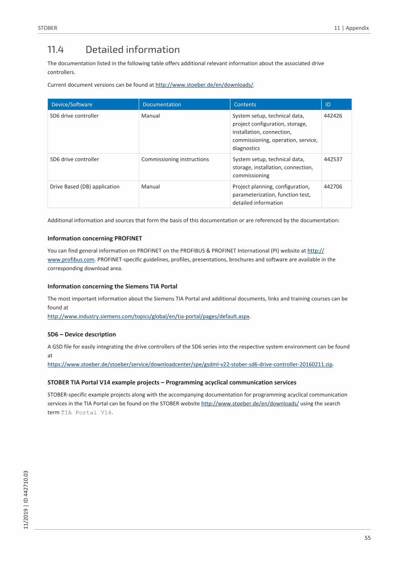
STOBER 11 | Appendix11
/201
9 |
ID 4
4271
0.03
55
11.4 Detailed informationThe documentation listed in the following table offers additional relevant information about the associated drivecontrollers.
Current document versions can be found at http://www.stoeber.de/en/downloads/.
Device/Software Documentation Contents ID
SD6 drive controller Manual System setup, technical data,project configuration, storage,installation, connection,commissioning, operation, service,diagnostics
442426
SD6 drive controller Commissioning instructions System setup, technical data,storage, installation, connection,commissioning
442537
Drive Based (DB) application Manual Project planning, configuration,parameterization, function test,detailed information
442706
Additional information and sources that form the basis of this documentation or are referenced by the documentation:
Information concerning PROFINET
You can find general information on PROFINET on the PROFIBUS & PROFINET International (PI) website at http://www.profibus.com. PROFINET-specific guidelines, profiles, presentations, brochures and software are available in thecorresponding download area.
Information concerning the Siemens TIA Portal
The most important information about the Siemens TIA Portal and additional documents, links and training courses can befound at http://www.industry.siemens.com/topics/global/en/tia-portal/pages/default.aspx.
SD6 – Device description
A GSD file for easily integrating the drive controllers of the SD6 series into the respective system environment can be foundathttps://www.stoeber.de/stoeber/service/downloadcenter/spe/gsdml-v22-stober-sd6-drive-controller-20160211.zip.
STOBER TIA Portal V14 example projects – Programming acyclical communication services
STOBER-specific example projects along with the accompanying documentation for programming acyclical communicationservices in the TIA Portal can be found on the STOBER website http://www.stoeber.de/en/downloads/ using the searchterm TIA Portal V14.

11 | Appendix STOBER
56
11/2
019
| ID
442
710.
03
11.5 Abbreviations
Abbreviation Meaning
BF Busfehler (en: Bus error)
CBA Component Based Automation
CPU Central Processing Unit
DCP Discovery and Configuration Protocol
DHCP Dynamic Host Configuration Protocol
DP Decentral peripherals
EMC Electromagnetic Compatibility
GSD General Station Description data
GSDML General Station Description Markup Language
HMI Human Machine Interface
HTTP Hypertext Transfer Protocol
IEC International Electrotechnical Commission
IEEE Institute of Electrical and Electronics Engineers
I/O Input/Output
IP Internet Protocol
IRT Isochronous Real-Time
LAN Local Area Network
LSB Least Significant Bit
MAC Media Access Control
PG Programmiergerät (en: Programming device)
PROFIBUS Process Field Bus
PROFINET Process Field Network
PZD Process Data
RDREC Read Record
RT Real-Time
RxD Receive data
SNMP Simple Network Management Protocol
PLC Programmable Logic Controller
TIA Totally Integrated Automation
TCP Transmission Control Protocol
TxD Transmit data
UDP User Data Protocol
WRREC Write Record

STOBER 12 | Contact11
/201
9 |
ID 4
4271
0.03
57
12 Contact
12.1 Consultation, service and addressWe would be happy to help you!
We offer a wealth of information and services to go with our products on our website:http://www.stoeber.de/en/service
For additional or personalized information, contact our consultation and support service: http://www.stoeber.de/en/support
Do you need our first-level support?: Phone +49 7231 582-3060 [email protected]
Call our 24-hour service hotline:Phone +49 7231 582-3000
Our address: STÖBER Antriebstechnik GmbH + Co. KGKieselbronner Strasse 12 75177 Pforzheim, Germany
12.2 Your opinion is important to usWe created this documentation to the best of our knowledge with the goal of helping you build and expand your expertiseproductively and efficiently with our products.
Your suggestions, opinions, wishes and constructive criticism help us to ensure and further develop the quality of ourdocumentation.If you want to contact us for a specific reason, we would be happy to receive an e-mail from you at:[email protected]
Thank you for your interest.Your STOBER editorial team

12 | Contact STOBER
58
11/2
019
| ID
442
710.
03
12.3 Close to customers around the worldWe offer you committed, expert advise and support in over 40 countries worldwide:
STOBER AUSTRIA www.stoeber.atPhone +43 7613 [email protected]
STOBER SOUTH EAST ASIA [email protected]
STOBER CHINA www.stoeber.cn Phone +86 10 6590 7391 [email protected]
STOBER SWITZERLAND www.stoeber.ch Phone +41 56 496 96 50 [email protected]
STOBER FRANCE www.stober.fr Phone +33 4 78.98.91.80 [email protected]
STOBER TAIWAN www.stober.tw Phone +886 4 2358 6089 [email protected]
STOBER ITALY www.stober.it Phone +39 02 93909570 [email protected]
STOBER TURKEY www.stober.com Phone +90 212 338 8014 [email protected]
STOBER JAPAN www.stober.co.jp Phone +81 3 5395 678 8 [email protected]
STOBER UNITED KINGDOM www.stober.co.uk Phone +44 1543 458 858 [email protected]
STOBER USA www.stober.com Phone +1 606 759 5090 [email protected]

STOBER Glossary11
/201
9 |
ID 4
4271
0.03
59
Glossary
100Base-TX
Ethernet network standard based on symmetrical copper cables in which the nodes are connected to a switch viacopper cables twisted in pairs (shielded twisted pair, CAT 5e quality level). 100Base-TX is the subsequent progressionfrom 10Base-T and includes those properties with the option of a transfer speed of 100 Mbps (Fast Ethernet).
Broadcast domain
Logical grouping of network devices within a local network that reaches all nodes via broadcast.
General station description file
Includes the technical features of a PROFINET IO device (type, configuration data, parameters, diagnostic information,etc.) in XML format in accordance with the GSDML specification. A GSD file serves as the configuration basis for projectconfiguration systems and is generally provided by the respective device manufacturer.
IO controller
Generally, a programmable logic controller that controls automation tasks and regulates data communication.
IO device
A decentralized field device that is assigned logically to a PROFINET IO controller that manages and controls it. An IO device consists of multiple modules and submodules.
IO supervisor
Generally, engineering software that can access all process and configuration data. An IO supervisor is only engagedtemporarily for parameterizing the IO devices, commissioning the IO system and for diagnostic purposes.
IPv4 limited broadcast
Type of broadcast in a network with IPv4 (Internet Protocol version 4). The IP address 255.255.255.255 is entered asthe destination. The content of the broadcast is not redirected by a router, which limits it to the local network.
MAC address
Also: Ethernet address. Hardware address for unique identification of a device in an Ethernet network. The MAC address is assigned by the manufacturer and consists of a 3-byte manufacturer ID and 3-byte device ID.
System function block
Logic block as part of a distributed, structured Siemens user program used to call up important system functions forPROFINET IO. Parameters for the associated input and output interfaces can be configured individually. The variablevalues stored in a function block are saved and are not lost after processing. Typical Siemens system function blocksare WRREC (Write record) and RDREC (Read record).

Glossary STOBER
60
11/2
019
| ID
442
710.
03
TCP/IP
Protocol family composed of the transmission control protocol (TCP) and the Internet protocol (IP). TCP is responsiblefor transmission, i.e. actual data traffic; IP handles unique communication with a PC in a network.
UDP/IP
Minimalist transport protocol for networks such as LAN that only provides the essential functions for data transport.UDP/IP is a simple service that functions without a continuous connection on both sides. There is no connection ordisconnection and no acknowledgment of the received data packets. There is the option to control data traffic using achecksum. As with TCP/IP, there are no troubleshooting mechanisms. Therefore, it is entirely possible for thetransferred data to experience data loss, data duplication or sequence errors.

STOBER List of figures11
/201
9 |
ID 4
4271
0.03
61
List of figuresFig. 1 PROFINET: Network structure......................................................................................................................... 12
Fig. 2 DS6 – Program interface ................................................................................................................................. 15
Fig. 3 DriveControlSuite: Navigation using text links and symbols........................................................................... 16
Fig. 4 TIA Portal – Program interface of the portal view .......................................................................................... 17
Fig. 5 TIA Portal – Program interface of the project view......................................................................................... 18
Fig. 6 PROFINET: Connection monitoring ................................................................................................................. 36
Fig. 7 LEDs for the PROFINET state ........................................................................................................................... 37
Fig. 8 LEDs for the state of the PROFINET network connection ............................................................................... 38
Fig. 9 RDREC system function block: Input and output parameters......................................................................... 44
Fig. 10 WRREC system function block: Input and output parameters........................................................................ 45
Fig. 11 RDREC flow...................................................................................................................................................... 46
Fig. 12 WRREC flow..................................................................................................................................................... 46
Fig. 13 PROFINET communication protocols ............................................................................................................. 47

List of tables STOBER
62
11/2
019
| ID
442
710.
03
List of tablesTab. 1 X200 and X201 connection description........................................................................................................... 14
Tab. 2 Parameter groups ........................................................................................................................................... 19
Tab. 3 Parameters – Data types, styles, possible values............................................................................................ 20
Tab. 4 Meaning of the red LED (BF) ........................................................................................................................... 37
Tab. 5 Meaning of the green LED (Run) ..................................................................................................................... 37
Tab. 6 Meaning of the green LEDs (Link) ................................................................................................................... 38
Tab. 7 Meaning of the yellow LEDs (Act.) .................................................................................................................. 38
Tab. 8 Event 52 – Causes and actions ........................................................................................................................ 39
Tab. 9 Parameters of the RDREC system function block............................................................................................ 44
Tab. 10 Parameters of the WRREC system function block........................................................................................... 45
Tab. 11 Groups and parameters .................................................................................................................................. 49
Tab. 12 RECORD request: Header structure ................................................................................................................ 50
Tab. 13 RECORD response: Header structure .............................................................................................................. 51
Tab. 14 RDREC, WRREC: Error codes............................................................................................................................ 52
Tab. 15 Attribute, format: Possible combinations ....................................................................................................... 53
Tab. 16 Process data modules .................................................................................................................................... 54
STÖBER Antriebstechnik GmbH + Co. KGKieselbronner Str. 1275177 PforzheimGermanyTel. +49 7231 [email protected]
442710.0311/2019
24 h-Service-Hotline+49 7231 582-3000
www.stober.com