PROFIBUS L2 DDE Server for SINEC CP5412 (A2)media.klinkmann.com/servers/docs/07015m35.pdf ·...
31
PROFIBUS L2 DDE Server for SINEC CP5412 (A2) for Microsoft Windows and InTouch Applications User Manual Ver 3.x Rev 3.5 DR 070 15 KLINKMANN AUTOMATION P.O. Box 38 FIN-00371 Helsinki Finland tel. int. + 358 9 5404940 fax int. + 358 9 5413541 www.klinkmann.com
Transcript of PROFIBUS L2 DDE Server for SINEC CP5412 (A2)media.klinkmann.com/servers/docs/07015m35.pdf ·...

PROFIBUS L2 DDE Server for SINEC CP5412 (A2)
for Microsoft Windows and InTouch Applications
User Manual Ver 3.x Rev 3.5
DR 070 15
KLINKMANN AUTOMATION P.O. Box 38
FIN-00371 Helsinki Finland tel. int. + 358 9 5404940 fax int. + 358 9 5413541
www.klinkmann.com

Klinkmann Automation PROFIBUS L2 DDE Server for SINEC CP5412(A2) i
PROFIBUS L2 DDE Server for SINEC CP5412 (A2) Ver 3.x User Manual Rev 3.4 07015m35
Table of Contents What is DDE? .....................................................................................................................1 Accessing a Remote DDE Item from Server.......................................................................2 Getting Started Quickly with the Server ..............................................................................2
Installing the Server.........................................................................................................2 Modifying PLC program...................................................................................................4
Modifying S5-95U PLC program..................................................................................4 Modifying S5-115U/S5-135U PLC program.................................................................4 Modifying S7-300 PLC program ..................................................................................5 Modifying PEP SMART I/O PLC program ...................................................................5
Configuring the CP5412 (A2) board ................................................................................6 Configuring the Server ....................................................................................................6
Configure DDE Server Settings Command .................................................................6 Board Configuration Command ...................................................................................7 Saving Server Configuration File .................................................................................8 Configuration File Location..........................................................................................8 Topic Definition Command ..........................................................................................9
Using the Server with InTouch..........................................................................................11 Defining the Tagnames .................................................................................................12 Controller "STATUS" Item.............................................................................................14
Item/Point Naming ............................................................................................................15 Item/Point Naming for S5-95U/S5-115U/S5-135U PLC ................................................15 Item/Point Naming for S7-300 PLC...............................................................................19 Item/Point Naming for PEP SMART I/O PLC................................................................21
Notes on Using Microsoft Excel ........................................................................................23 Reading Values into Excel Spreadsheets .....................................................................23 Writing Values to Server Points ....................................................................................23
Error messages ................................................................................................................24 Error messages output in Server window......................................................................24 Error messages output in WWLogger window ..............................................................25
Troubleshooting ................................................................................................................28

Klinkmann Automation PROFIBUS L2 DDE Server for SINEC CP5412 (A2) 1
PROFIBUS L2 DDE Server for SINEC CP5412 (A2) Ver 3.x User Manual Rev 3.5 07015m35
PROFIBUS L2 DDE Server
The PROFIBUS L2 DDE Server for SINEC CP5412 (A2) (hereafter referred to as the “PROFIBUS L2 DDE Server” or “Server”) is a Microsoft Windows NT application program that acts as a DDE (Dynamic Data Exchange) Server and allows other Windows application programs to access data from SIMATIC S5-95U, S5-115U, S5-135U, S7-300 and PEP SMART I/O PLCs using PROFIBUS Layer 2 (FDL) protocol. The Server communicates with PLCs using the CP5412 (A2) communication processor, installed in an IBM PC or compatible computer and connected to the PROFIBUS bus cable via bus terminal. The Server allows to access data in up to 30 PLCs attached to the PROFIBUS network. The Server is primarily intended for use with Wonderware InTouch, but it may be used by any Microsoft Windows NT program that is capable of acting as a DDE Client.
What is DDE? DDE is a complete communication protocol designed by Microsoft to allow applications in the Windows environment to send/receive data and instructions to/from each other. It implements a client-server relationship between two concurrently running applications. The server application provides the data and accepts requests from any other application interested in its data. Requesting applications are called clients. Some applications such as InTouch and Excel can simultaneously be both a client and server. To obtain data from another application the client program opens a channel to the server application by specifying three things: the server application name, the topic name and the specific item name. For example, in the case of Excel, the application name is "Excel", the topic name is the name of the specific spreadsheet that contains the data and the item name is the specific cell on the spreadsheet. With InTouch the application name is "View", the topic name is the word "Tagname" when reading/writing to an InTouch tagname and the item name is a specific tagname in the InTouch Data Dictionary. When a client application sets up a link to another DDE program, it requests the server application to advise the client whenever a specific item's value changes. These data links will remain active until either the client or server program terminates the link or the conversation. They are a very efficient means of exchanging data because when the link has been established no communication occurs until the specified data value changes. InTouch uses DDE to communicate with I/O device drivers and other DDE application programs.

Klinkmann Automation PROFIBUS L2 DDE Server for SINEC CP5412 (A2) 2
PROFIBUS L2 DDE Server for SINEC CP5412 (A2) Ver 3.x User Manual Rev 3.5 07015m35
Accessing a Remote DDE Item from Server The DDE protocol identifies an element of data by using a three-part address, including: Application, Topic and Item. Application refers to the name of the Windows program (server) that knows how to access the data element. In the case of data coming from or going to PLCs, the application portion of the DDE address is PROFIBUS. Topic is an application-specific sub-group of data elements. The Server considers each PLC to be a separate topic. Up to 30 PLCs may be connected, and the user creates a meaningful name for each of them and use this name as the topic name for DDE references. Note: In some cases, the term "node" is used interchangeably with the term "topic". Item indicates a specific data element within the specified topic. For the Server, an item is an individual data bit, byte, word, etc., in the PLC. (The item/point names are defined by the Server as described in the Item/Point Naming section.) Note: In some cases, the term "point" is used interchangeably with the term "item".
Getting Started Quickly with the Server Follow these steps:
1. Install the PROFIBUS L2 DDE Server. 2. Modify PLC program. 3. Configure CP5412 (A2) board. 4. Reboot computer. 5. Start MS Windows NT. 6. Start and configure PROFIBUS L2 DDE Server. 7. Start Client.
Installing the Server The PROFIBUS L2 DDE Server installation package can be supplied: 1. As a self-extracting archive 07015xxx.EXE if downloaded from Klinkmann’s web site
(the xxx is the current (latest) version of the Server). 2. From installation on CD. 3. On two or three distribution disks (floppies). To install the PROFIBUS L2 DDE Server from the self-extracting archive, run the 07015xxx.EXE and proceed as directed by the PROFIBUS L2 DDE Server Setup program.

Klinkmann Automation PROFIBUS L2 DDE Server for SINEC CP5412 (A2) 3
PROFIBUS L2 DDE Server for SINEC CP5412 (A2) Ver 3.x User Manual Rev 3.5 07015m35
To install the PROFIBUS L2 DDE Server from CD or distribution disks (floppies), on MS Windows NT: 1. Insert the CD with Klinkmann Software into CD drive or insert PROFIBUS L2 DDE
Disk1 into a floppy drive A: or B:. 2. Select the Run command under the Start menu. 3. Run STARTUP.EXE if installing from CD or SETUP.EXE if installing from distribution
disks (floppies). 4. If installing from CD: select “Protocol Servers (DDE, SuiteLink, OPC)”, find “PROFIBUS
L2 DDE Server” and click on “Setup…”. 5. Proceed as directed by the PROFIBUS L2 DDE Server Setup program. When installation is finished, the subdirectory specified as a folder where to install the PROFIBUS L2 DDE Server will contain the following files: PROFIBUS.EXE The PROFIBUS L2 Server Program. This is a Microsoft
Windows 32-bit application program.
PROFIBUS.HLP The PROFIBUS L2 Server Help file.
PROFIBUS.CFG An example configuration file.
LICENSE.TXT
Klinkmann Automation software license file.
WWCOMDLG.DLL
Dynamic Link Library necessary for PROFIBUS L2 Server.
ADDITION.ZIP Contains additional files (InTouch application examples etc.). For detailed information, how to use these files, read the README.TXT file included.
To uninstall the PROFIBUS L2P Server, start Control Panel, select “Add/Remove Programs” and select the “PROFIBUS L2 DDE Server” from the list of available software products. Click on “Add/Remove…” and proceed as directed by the UnInstallShield program. Note: The HASP key is needed for full time running of PROFIBUS L2 Server. The HASP Driver setup is performed during the Server setup. Without HASP Driver installed, the PROFIBUS L2 Server will run only 1 hour (with all features enabled).

Klinkmann Automation PROFIBUS L2 DDE Server for SINEC CP5412 (A2) 4
PROFIBUS L2 DDE Server for SINEC CP5412 (A2) Ver 3.x User Manual Rev 3.5 07015m35
Modifying PLC program To enable PLC program to communicate with PROFIBUS L2 DDE Server, modify it as described below for various PLC types. PLC demo programs are stored in subdirectory ADDITION on distribution diskette. Read ADDITION\README.TXT file for more information. Modifying S5-95U PLC program Modify DB1 of your PLC program. As a prerequisite for using Interpreter Function Blocks, you must specify a SAP number and define status and length bytes in DB1. Interpreter Function Blocks use 33 SAP for communication and flag bytes 2...6 as a status, length and internal data bytes. They must not be used for other purposes. If it is necessary to use other SAP number and flag bytes, than DB1, DB101 and FB104, FB105 must be changed appropriately. Below is an example of DB1 fragment: 156: KS = ‘ SL2: TLN 10 STA AKT ‘; 168: KS = ‘ BDR 500 HSA 32 TRT ‘; 180: KS = ‘160000 SET 80 ST 1000 ‘; 192: KS = ‘SDT 1 80 SDT 2 360 ‘; 204: KS = ‘STBS 33 MB2 STBR 33 MB4 ‘; 324: KS = ‘ ; ERT: ERR MW0 ; END ‘; Copy FB104, FB105 and DB101, DB102 from [email protected] demo program to your PLC program. Include call to Interpreter Function Block FB104. In order to receive/send the data requested by Server, the PLC program should call Interpreter Function Block FB104 on each program cycle. Transfer program to PLC and start it. Modifying S5-115U/S5-135U PLC program Configure PLC communication processor with SINEC NCM (in case of demo program, just transfer ready configuration data file OTL2115 (OTL2135 for S5-135U) to communication processor). Copy FB101-FB104 and DB101-DB103 from TL2115ST.S5D (TL2135ST.S5D for S5-135U) to your PLC program. Include call to Interpreter Function Block FB104. In order to receive/send the data requested by Server, the PLC program should call Interpreter Function Block FB104 on each program cycle. Interpreter Function Blocks use interface number SSNR 0, job number ANR 134 for communication and flag bytes 2...6 as condition code word ANZW and internal data bytes. They must not be used for other purposes. If it is necessary to use other SSNR, ANR or flag bytes, than FB101-FB104 must be changed appropriately. Transfer program to PLC and start it.

Klinkmann Automation PROFIBUS L2 DDE Server for SINEC CP5412 (A2) 5
PROFIBUS L2 DDE Server for SINEC CP5412 (A2) Ver 3.x User Manual Rev 3.5 07015m35
Modifying S7-300 PLC program Copy FB101 and DB101 from S7-300\FDL demo program to your PLC program. Include call to Interpreter Function Block FB101. In order to receive/send the data requested by Server, the PLC program should call Interpreter Function Block FB101 on each program cycle. Transfer program to PLC and start it. Modifying PEP SMART I/O PLC program Create ISaGRAF application and configuration file ISAPB2_S.TXT. Transfer ISaGRAF application (with ISaGRAF debugger) and configuration file (with MS Windows 3.x TERMINAL) to PLC. Set bus parameters for station (with PBMODE command from MS Windows 3.x TERMINAL).

Klinkmann Automation PROFIBUS L2 DDE Server for SINEC CP5412 (A2) 6
PROFIBUS L2 DDE Server for SINEC CP5412 (A2) Ver 3.x User Manual Rev 3.5 07015m35
Configuring the CP5412 (A2) board Start SINEC Configuration CP 5412 (A2) program from SINEC Setup program. Enter PC hardware parameters and L2 bus parameters. Select PROFIBUS (+FDL)-5412 protocol. Take into consideration, that parameter values must be compatible with those of other network stations. If MS Windows 3.x is used, then transfer configured parameters to CP 5412 (A2) by running SINECINI.BAT batch file, before starting MS Windows 3.x.
Configuring the Server After the Server is initially installed, some configuration is required. During configuration Server creates a PROFIBUS.CFG file which contains all entered topic (PLC) definitions, as well as some board settings. This file will automatically be placed in the same directory as PROFIBUS.EXE, unless the path where the configuration file will be placed is specified via the /Configure/DDE Server Settings command. To perform the required configuration, start the PROFIBUS.EXE program. PROFIBUS main window will appear:
To access the commands used for configuration, open the /Configure menu:
Configure DDE Server Settings Command To change Server’s internal parameters, invoke the /Configure/DDE Server Settings command. The DDE Server Settings dialog box will appear:

Klinkmann Automation PROFIBUS L2 DDE Server for SINEC CP5412 (A2) 7
PROFIBUS L2 DDE Server for SINEC CP5412 (A2) Ver 3.x User Manual Rev 3.5 07015m35
The following describes each field in this dialog box: Protocol Timer Tick This field is used to set the frequency at which the Server checks for work to do. The minimum value is 50 milliseconds for Windows 3.x and 10 milliseconds for Windows NT. NetDDE being used Select this option if you are networking using NetDDE. Configuration File Directory This field is used to specify the path (disk drive and directory) in which Server will save its current configuration file. Server will use this path to load the configuration file the next time it is started. Note: Only the "path" may be modified with this field. The configuration file is always named PROFIBUS.CFG. There is no limit to the number of configuration files created, although each must be in a separate directory. When using the Server with InTouch, it is a good practice to place the configuration file in the application directory. Board Configuration Command This command is used to configure the interface board (communication processor) that will be used to communicate with the PLCs in the PROFIBUS network. Note, that board must be configured before definition of topics. Invoke the /Configure/Board Configuration command. The Select an Interface Board dialog box will appear:
Select a Board and click on Modify to examine the characteristics of the selected Board. The Board Configuration dialog box will appear:

Klinkmann Automation PROFIBUS L2 DDE Server for SINEC CP5412 (A2) 8
PROFIBUS L2 DDE Server for SINEC CP5412 (A2) Ver 3.x User Manual Rev 3.5 07015m35
The following describes each dialog field in this dialog box: Board Name This field is used to enter the interface board name. Reply Timeout This field is used to enter the amount of time (in seconds) all PLCs using the selected interface board will be given to reply to commands from the Server. Note: The default value of 3 seconds should be sufficient for most configurations. When all entries have been made, click on OK to process the configuration for the interface board. Saving Server Configuration File If the configuration file does not currently exist, or a new configuration path has been specified, the Server will display the Saving PROFIBUS Configuration dialog box:
This dialog box displays the path where the Server is going to save the current configuration file. The path may be changed if necessary. Also, the path can optionally be recorded in the WIN.INI file by selecting the Make this the default configuration option. Doing so it will allow the Server to find the configuration file automatically each time it is started. Configuration File Location When the Server starts up, it first attempts to locate its configuration file by, first checking the WIN.INI file for a path which was previously specified. If the path is not present in the WIN.INI file, the Server will assume that the current working directory is to be used.

Klinkmann Automation PROFIBUS L2 DDE Server for SINEC CP5412 (A2) 9
PROFIBUS L2 DDE Server for SINEC CP5412 (A2) Ver 3.x User Manual Rev 3.5 07015m35
To start the Server with configuration file other than the default configuration file, a special switch (/d:) is used. For example, invoke the Run command and enter the following command: PROFIBUS /d:c:\path Note: There is no limit to the number of configuration files that may be created, although each must be in a separate directory. Topic Definition Command The user provides each PLC with an arbitrary name which is used as the DDE topic for all references to this PLC. The following steps are taken to define the Topics attached to the PLCs: 1. Invoke the /Configure/Topic Definition command. The Select a Topic dialog box will appear:
2. To modify an existing topic, select the topic name and click on Modify. To define a
new topic, click on New. The Topic Definition dialog box will appear:

Klinkmann Automation PROFIBUS L2 DDE Server for SINEC CP5412 (A2) 10
PROFIBUS L2 DDE Server for SINEC CP5412 (A2) Ver 3.x User Manual Rev 3.5 07015m35
3. Enter the Topic Name which corresponds to the DDE Topic Name. (The DDE Topic Name is entered in the DDE Access Name Definition dialog box described in the Using the Server with InTouch section.)
4. Set the Maximum Supported Points for topic (PLC). Set the maximum number of
really used (polled) items/points - this will reduce the amount of memory used by the Server.
5. Set the Update Interval field to indicate the frequency the items/points on this topic
will be read (polled). 6. Click on the Remote Station Type button to select PLC. 7. Enter the Remote Station Number of the PLC (this value should coincide with TLN
parameter in S5-95U PLC’s DB1, parameter L2 address set by SINEC NCM in case of S5-115U/S5-135U PLC, parameter Local L2 address set by NCM S7 for PROFIBUS in case of S7-300 PLC or station address set by PBMODE command in case of PEP SMART I/O PLC).
Note: Each PLC must have a Station Number from 1 to 31.
8. Enter the Remote SAP of the PLC. This value should coincide with STBS and STBR parameters in S5-95U PLC’s DB1. In case of S5-115U/S5-135U PLC, Remote SAP value should be equal to LSAP parameter, set during editing of free layer 2 links with SINEC NCM. In case of S7-300 PLC, this value should be equal to Local LSAP parameter, set during editing of FDL connections with NCM S7 for PROFIBUS. In case of PEP SMART I/O PLC, this value should be equal to number of SAP for reception of SDA/SDN requests set in configuration file ISAPB2_S.TXT. Number of SAP for reception of SRD requests must be equal to Remote SAP + 1. The same SAP numbers should be used in all communication references in ISAPB2_S.TXT file.
9. Enter the Local SAP for the CP 5412 (A2) board. In case of S7-300 PLC, this value
should be equal to Remote LSAP parameter, set during editing of FDL connections with NCM S7 for PROFIBUS. In case of PEP SMART I/O PLC, this value should be equal to r_sap parameter, set in configuration file ISAPB2_S.TXT.
10. Edit the PLC Data Area Addresses, if necessary.
Note: PLC Data Area Addresses are set by default, depending on selected PLC type, and usually their editing is not necessary. If the address is not used by the PLC, its initial value is set to 0 by default, and its editing will not influence Servers work in any way.
When all entries have been made, click on OK to process the configuration for this topic.

Klinkmann Automation PROFIBUS L2 DDE Server for SINEC CP5412 (A2) 11
PROFIBUS L2 DDE Server for SINEC CP5412 (A2) Ver 3.x User Manual Rev 3.5 07015m35
Using the Server with InTouch To access items/points on the PLCs from InTouch, the following steps (all performed in WindowMaker) are required: To define the DDE Access Names in WindowMaker, invoke the /Special/DDE Access Name command. The DDE Access Name Definition dialog box will appear.
Click on Add. The Add DDE Access Name dialog box will appear:
Note: If Add is selected, this dialog box will be blank when it initially appears. Data has been entered here to illustrate the entries which are made. The following three fields are required entries when entering a DDE Access Name Definition: DDE Access Name Enter an arbitrary name which will be used by InTouch to refer to the topic (PLC). For simplicity, it is recommended that the name defined for the topic in Server is also used here. DDE Application/Server Name Enter Server name PROFIBUS.

Klinkmann Automation PROFIBUS L2 DDE Server for SINEC CP5412 (A2) 12
PROFIBUS L2 DDE Server for SINEC CP5412 (A2) Ver 3.x User Manual Rev 3.5 07015m35
DDE Topic Name Enter the name defined for the topic in Server to identify the PLC, the Server will be accessing. Request Initial Data This option may be selected if the Server is other than a Wonderware DDE Server and the Server does not return data values immediately when a window is displayed. This option is not applicable to the PROFIBUS L2 DDE Server. Wait for Change This option should be selected when the DDE application is a Wonderware DDE Server. Advise all Items This option may be selected if the Server is to poll for all data whether or not it is in visible windows, alarmed, logged or trended. The use of the option is not recommended. Advise only active Items Selecting this option will cause the Server to poll only points in visible windows and points that are alarmed, logged or trended.
Defining the Tagnames To define the Tagnames associated with the new DDE Access Name, invoke the /Special/Tag Name Dictionary command (in WindowMaker). The Dictionary - Tagname Definition dialog box will appear:
Click on New and enter the Tagname. (The tagname defined here is the name InTouch will use. The Server does not see this name.) Select the tag type by clicking on the Type button. The Choose tag type dialog box will appear:
Klinkmann Automation PROFIBUS L2 DDE Server for SINEC CP5412 (A2) 13
PROFIBUS L2 DDE Server for SINEC CP5412 (A2) Ver 3.x User Manual Rev 3.5 07015m35
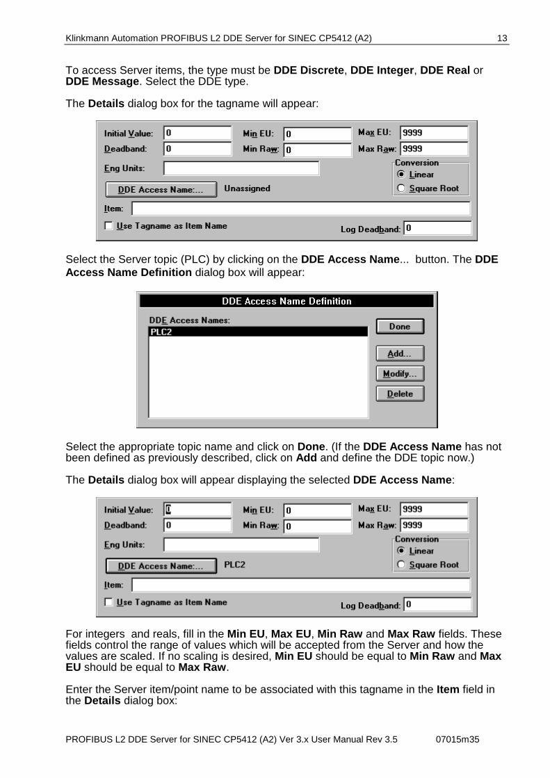
To access Server items, the type must be DDE Discrete, DDE Integer, DDE Real or DDE Message. Select the DDE type. The Details dialog box for the tagname will appear:
Select the Server topic (PLC) by clicking on the DDE Access Name... button. The DDE Access Name Definition dialog box will appear:
Select the appropriate topic name and click on Done. (If the DDE Access Name has not been defined as previously described, click on Add and define the DDE topic now.) The Details dialog box will appear displaying the selected DDE Access Name:
For integers and reals, fill in the Min EU, Max EU, Min Raw and Max Raw fields. These fields control the range of values which will be accepted from the Server and how the values are scaled. If no scaling is desired, Min EU should be equal to Min Raw and Max EU should be equal to Max Raw. Enter the Server item/point name to be associated with this tagname in the Item field in the Details dialog box:

Klinkmann Automation PROFIBUS L2 DDE Server for SINEC CP5412 (A2) 14
PROFIBUS L2 DDE Server for SINEC CP5412 (A2) Ver 3.x User Manual Rev 3.5 07015m35
Refer to the Item/Point Naming section below for details. When all entries have been made, click on the Save button (in the top dialog box) to accept the new tagname. To define additional tagnames click on the New button. To return to the WindowMaker main screen, click on Done.
Controller "STATUS" Item For each Controller, there is a built-in discrete item which indicates the state of communication with the Controller. The discrete item (STATUS) is set to 0 when communication with the Controller fails and set to 1 when communication is successful. From InTouch the state of communication with the Controller may be read by defining a DDE Discrete tagname and associating it with the topic configured for the Controller and using STATUS as the Item name.
From Excel, the status of the communication may be read by entering the following formula in a cell: =PROFIBUS|topic!STATUS
Klinkmann Automation PROFIBUS L2 DDE Server for SINEC CP5412 (A2) 15
PROFIBUS L2 DDE Server for SINEC CP5412 (A2) Ver 3.x User Manual Rev 3.5 07015m35
Item/Point Naming
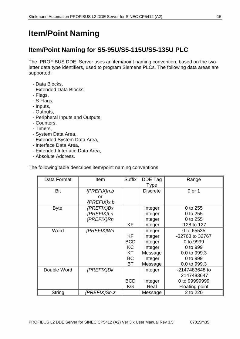
Item/Point Naming for S5-95U/S5-115U/S5-135U PLC The PROFIBUS DDE Server uses an item/point naming convention, based on the two-letter data type identifiers, used to program Siemens PLCs. The following data areas are supported: - Data Blocks, - Extended Data Blocks, - Flags, - S Flags, - Inputs, - Outputs, - Peripheral Inputs and Outputs, - Counters, - Timers, - System Data Area, - Extended System Data Area, - Interface Data Area, - Extended Interface Data Area, - Absolute Address. The following table describes item/point naming conventions:
Data Format Item Suffix DDE Tag Type
Range
Bit {PREFIX}n.b or
{PREFIX}x.b
Discrete 0 or 1
Byte {PREFIX}Bx {PREFIX}Ln {PREFIX}Rn
KF
Integer Integer Integer Integer
0 to 255 0 to 255 0 to 255
-128 to 127 Word {PREFIX}Wn
KF BCD KC KT BC BT
Integer Integer Integer Integer
Message Integer
Message
0 to 65535 -32768 to 32767
0 to 9999 0 to 999
0.0 to 999.3 0 to 999
0.0 to 999.3 Double Word
{PREFIX}Dk
BCD KG
Integer
Integer Real
-2147483648 to 2147483647
0 to 99999999 Floating point
String {PREFIX}Sn.z Message 2 to 220
Klinkmann Automation PROFIBUS L2 DDE Server for SINEC CP5412 (A2) 16
PROFIBUS L2 DDE Server for SINEC CP5412 (A2) Ver 3.x User Manual Rev 3.5 07015m35
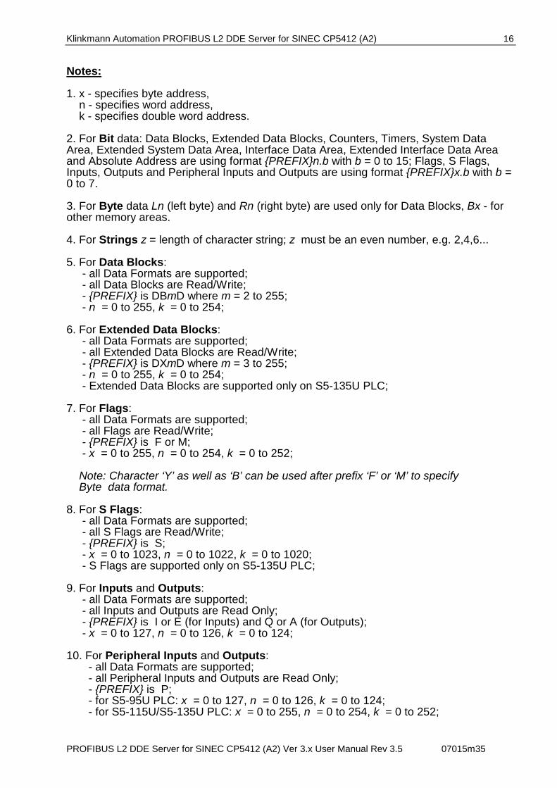
Notes: 1. x - specifies byte address, n - specifies word address, k - specifies double word address. 2. For Bit data: Data Blocks, Extended Data Blocks, Counters, Timers, System Data Area, Extended System Data Area, Interface Data Area, Extended Interface Data Area and Absolute Address are using format {PREFIX}n.b with b = 0 to 15; Flags, S Flags, Inputs, Outputs and Peripheral Inputs and Outputs are using format {PREFIX}x.b with b = 0 to 7. 3. For Byte data Ln (left byte) and Rn (right byte) are used only for Data Blocks, Bx - for other memory areas. 4. For Strings z = length of character string; z must be an even number, e.g. 2,4,6... 5. For Data Blocks: - all Data Formats are supported; - all Data Blocks are Read/Write; - {PREFIX} is DBmD where m = 2 to 255; - n = 0 to 255, k = 0 to 254; 6. For Extended Data Blocks: - all Data Formats are supported; - all Extended Data Blocks are Read/Write; - {PREFIX} is DXmD where m = 3 to 255; - n = 0 to 255, k = 0 to 254; - Extended Data Blocks are supported only on S5-135U PLC; 7. For Flags: - all Data Formats are supported; - all Flags are Read/Write; - {PREFIX} is F or M; - x = 0 to 255, n = 0 to 254, k = 0 to 252; Note: Character ‘Y’ as well as ‘B’ can be used after prefix ‘F’ or ‘M’ to specify Byte data format. 8. For S Flags: - all Data Formats are supported; - all S Flags are Read/Write; - {PREFIX} is S; - x = 0 to 1023, n = 0 to 1022, k = 0 to 1020; - S Flags are supported only on S5-135U PLC; 9. For Inputs and Outputs: - all Data Formats are supported; - all Inputs and Outputs are Read Only; - {PREFIX} is I or E (for Inputs) and Q or A (for Outputs); - x = 0 to 127, n = 0 to 126, k = 0 to 124; 10. For Peripheral Inputs and Outputs: - all Data Formats are supported; - all Peripheral Inputs and Outputs are Read Only; - {PREFIX} is P; - for S5-95U PLC: x = 0 to 127, n = 0 to 126, k = 0 to 124; - for S5-115U/S5-135U PLC: x = 0 to 255, n = 0 to 254, k = 0 to 252;
Klinkmann Automation PROFIBUS L2 DDE Server for SINEC CP5412 (A2) 17
PROFIBUS L2 DDE Server for SINEC CP5412 (A2) Ver 3.x User Manual Rev 3.5 07015m35
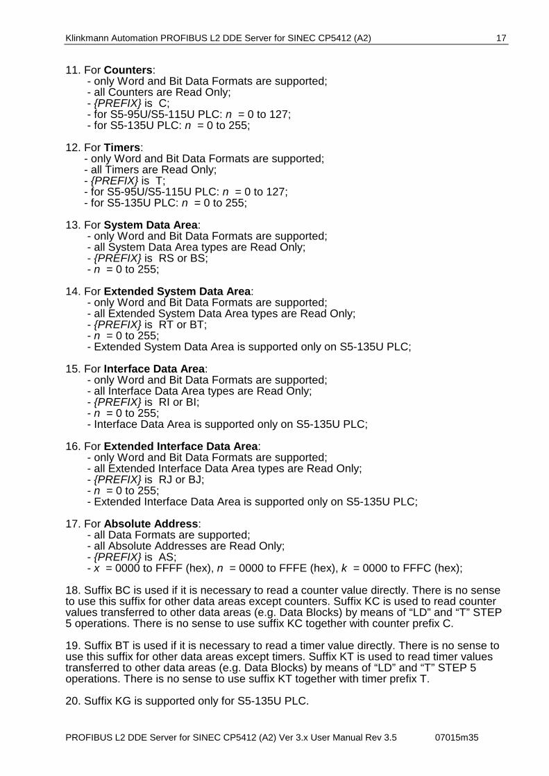
11. For Counters: - only Word and Bit Data Formats are supported; - all Counters are Read Only; - {PREFIX} is C; - for S5-95U/S5-115U PLC: n = 0 to 127; - for S5-135U PLC: n = 0 to 255; 12. For Timers: - only Word and Bit Data Formats are supported; - all Timers are Read Only; - {PREFIX} is T; - for S5-95U/S5-115U PLC: n = 0 to 127; - for S5-135U PLC: n = 0 to 255; 13. For System Data Area: - only Word and Bit Data Formats are supported; - all System Data Area types are Read Only; - {PREFIX} is RS or BS; - n = 0 to 255; 14. For Extended System Data Area: - only Word and Bit Data Formats are supported; - all Extended System Data Area types are Read Only; - {PREFIX} is RT or BT; - n = 0 to 255; - Extended System Data Area is supported only on S5-135U PLC; 15. For Interface Data Area: - only Word and Bit Data Formats are supported; - all Interface Data Area types are Read Only; - {PREFIX} is RI or BI; - n = 0 to 255; - Interface Data Area is supported only on S5-135U PLC; 16. For Extended Interface Data Area: - only Word and Bit Data Formats are supported; - all Extended Interface Data Area types are Read Only; - {PREFIX} is RJ or BJ; - n = 0 to 255; - Extended Interface Data Area is supported only on S5-135U PLC; 17. For Absolute Address: - all Data Formats are supported; - all Absolute Addresses are Read Only; - {PREFIX} is AS; - x = 0000 to FFFF (hex), n = 0000 to FFFE (hex), k = 0000 to FFFC (hex); 18. Suffix BC is used if it is necessary to read a counter value directly. There is no sense to use this suffix for other data areas except counters. Suffix KC is used to read counter values transferred to other data areas (e.g. Data Blocks) by means of “LD” and “T” STEP 5 operations. There is no sense to use suffix KC together with counter prefix C. 19. Suffix BT is used if it is necessary to read a timer value directly. There is no sense to use this suffix for other data areas except timers. Suffix KT is used to read timer values transferred to other data areas (e.g. Data Blocks) by means of “LD” and “T” STEP 5 operations. There is no sense to use suffix KT together with timer prefix T. 20. Suffix KG is supported only for S5-135U PLC.

Klinkmann Automation PROFIBUS L2 DDE Server for SINEC CP5412 (A2) 18
PROFIBUS L2 DDE Server for SINEC CP5412 (A2) Ver 3.x User Manual Rev 3.5 07015m35
Item/Point Naming Examples: DB10D20.15
data block 10 bit 15 of data word 20
DB10DL20 data block 10 left byte of data word 20 value in the PLC is binary and has a range of 0 to 255
DB10DW20KF
data block 10 data word 20 value in the PLC is binary and has a range of -32768 to 32767
DB10DW20BCD
data block 10 data word 20 value in the PLC is in BCD format and has a range of 0 to 9999
DB10DS20.8
data block 10 value in the PLC is character string containing 8 bytes and starting at data word 20
DB10DW20KC
data block 10 data word 20 value in the PLC is in counter constant format and has a range of 0 to 999
DB10DW20KT
data block 10 data word 20 value in the PLC is in timer constant format and has a range of 0.0 to 999.3
FB100
flag byte 100 value in the PLC is binary and has a range of 0 to 255
FW100BCD
flag word starting at flag byte 100 value in the PLC is in BCD format and has a range of 0 to 9999
I32.0
bit 0 of input byte 32 TW0BT
timer word 0 value in the PLC is in binary timer format
Klinkmann Automation PROFIBUS L2 DDE Server for SINEC CP5412 (A2) 19
PROFIBUS L2 DDE Server for SINEC CP5412 (A2) Ver 3.x User Manual Rev 3.5 07015m35
CW10BC counter word 10 value in the PLC is in binary counter format
RS10.5
bit 5 of System Data word 10
ASS5F00.10 value in the PLC is character string containing 10 bytes and starting at absolute address 5F00 (Hex)
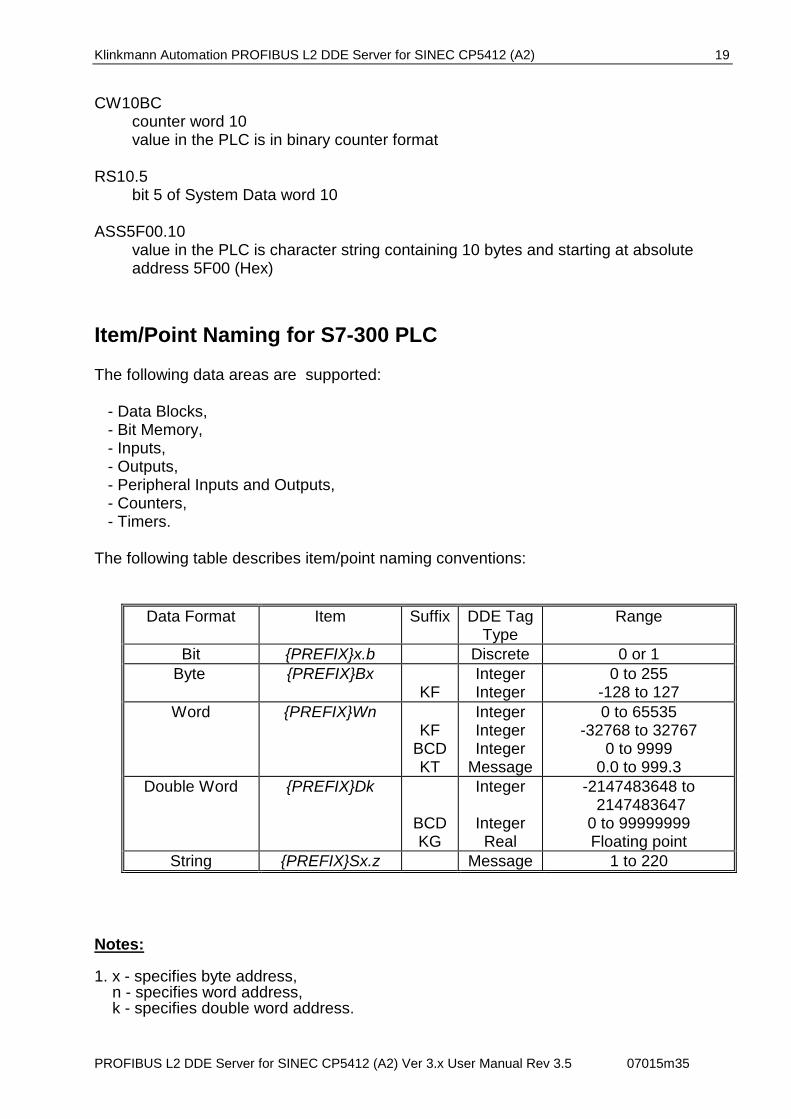
Item/Point Naming for S7-300 PLC The following data areas are supported: - Data Blocks, - Bit Memory, - Inputs, - Outputs, - Peripheral Inputs and Outputs, - Counters, - Timers. The following table describes item/point naming conventions:
Data Format Item Suffix DDE Tag Type
Range
Bit {PREFIX}x.b Discrete 0 or 1 Byte {PREFIX}Bx
KF Integer Integer
0 to 255 -128 to 127
Word {PREFIX}Wn KF
BCD KT
Integer Integer Integer
Message
0 to 65535 -32768 to 32767
0 to 9999 0.0 to 999.3
Double Word
{PREFIX}Dk
BCD KG
Integer
Integer Real
-2147483648 to 2147483647
0 to 99999999 Floating point
String {PREFIX}Sx.z Message 1 to 220 Notes: 1. x - specifies byte address, n - specifies word address, k - specifies double word address.
Klinkmann Automation PROFIBUS L2 DDE Server for SINEC CP5412 (A2) 20
PROFIBUS L2 DDE Server for SINEC CP5412 (A2) Ver 3.x User Manual Rev 3.5 07015m35
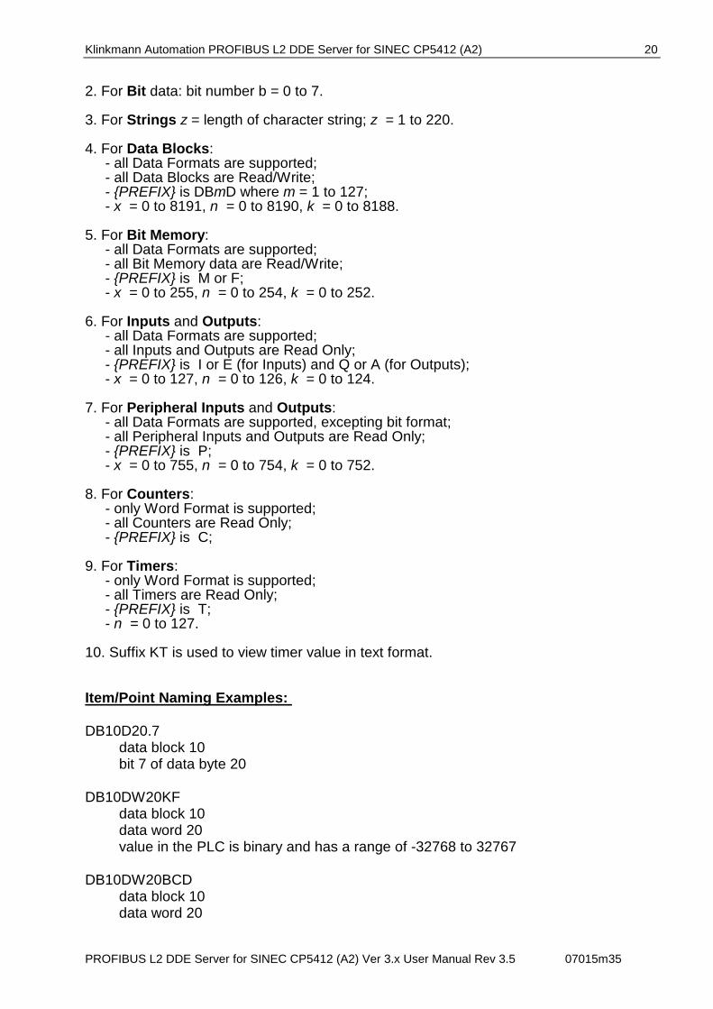
2. For Bit data: bit number b = 0 to 7. 3. For Strings z = length of character string; z = 1 to 220. 4. For Data Blocks: - all Data Formats are supported; - all Data Blocks are Read/Write; - {PREFIX} is DBmD where m = 1 to 127; - x = 0 to 8191, n = 0 to 8190, k = 0 to 8188. 5. For Bit Memory: - all Data Formats are supported; - all Bit Memory data are Read/Write; - {PREFIX} is M or F; - x = 0 to 255, n = 0 to 254, k = 0 to 252. 6. For Inputs and Outputs: - all Data Formats are supported; - all Inputs and Outputs are Read Only; - {PREFIX} is I or E (for Inputs) and Q or A (for Outputs); - x = 0 to 127, n = 0 to 126, k = 0 to 124. 7. For Peripheral Inputs and Outputs: - all Data Formats are supported, excepting bit format; - all Peripheral Inputs and Outputs are Read Only; - {PREFIX} is P; - x = 0 to 755, n = 0 to 754, k = 0 to 752. 8. For Counters: - only Word Format is supported; - all Counters are Read Only; - {PREFIX} is C; 9. For Timers: - only Word Format is supported; - all Timers are Read Only; - {PREFIX} is T; - n = 0 to 127. 10. Suffix KT is used to view timer value in text format. Item/Point Naming Examples: DB10D20.7
data block 10 bit 7 of data byte 20
DB10DW20KF data block 10 data word 20 value in the PLC is binary and has a range of -32768 to 32767
DB10DW20BCD
data block 10 data word 20
Klinkmann Automation PROFIBUS L2 DDE Server for SINEC CP5412 (A2) 21
PROFIBUS L2 DDE Server for SINEC CP5412 (A2) Ver 3.x User Manual Rev 3.5 07015m35
value in the PLC is in BCD format and has a range of 0 to 9999
DB10DS20.8 data block 10 value in the PLC is character string containing maximum 8 bytes and starting at data byte 20
MB100
Bit memory byte 100 value in the PLC is binary and has a range of 0 to 255
I4.0
bit 0 of input byte 4
TW0KT timer word 0 in text format
CW10
counter word 10
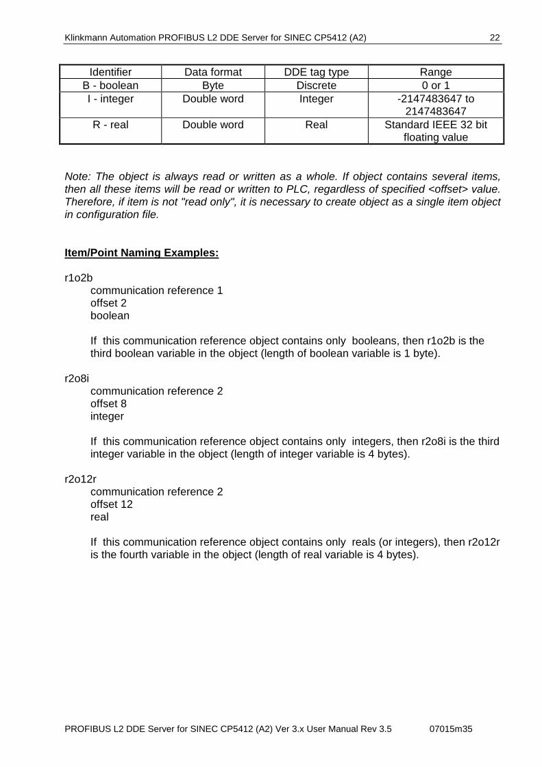
Item/Point Naming for PEP SMART I/O PLC It is assumed that PEP SMART I/O PLC uses PROFIBUS implementation on ISaGRAF for communication via PROFIBUS Layer 2. Therefore special configuration file containing description of communication references and objects must be downloaded to target PLC. PROFIBUS L2 DDE Server uses communication reference numbers in item/point naming. PROFIBUS L2 DDE Server uses the following item/point name format for PEP SMART I/O PLC: R<remote communication reference>O<offset><data type> where: <remote communication reference> - communication reference number in remote PLC's configuration file. Valid range: 0...65535. <offset> - relative address of the item in object (each communication reference has object linked to it). Valid range: 0...(object length in bytes - 1 ). <data type> - item data type identifier.
Klinkmann Automation PROFIBUS L2 DDE Server for SINEC CP5412 (A2) 22
PROFIBUS L2 DDE Server for SINEC CP5412 (A2) Ver 3.x User Manual Rev 3.5 07015m35
Identifier Data format DDE tag type Range B - boolean Byte Discrete 0 or 1 I - integer Double word Integer -2147483647 to
2147483647 R - real Double word Real Standard IEEE 32 bit
floating value Note: The object is always read or written as a whole. If object contains several items, then all these items will be read or written to PLC, regardless of specified <offset> value. Therefore, if item is not "read only", it is necessary to create object as a single item object in configuration file. Item/Point Naming Examples: r1o2b
communication reference 1 offset 2 boolean If this communication reference object contains only booleans, then r1o2b is the third boolean variable in the object (length of boolean variable is 1 byte).
r2o8i
communication reference 2 offset 8 integer If this communication reference object contains only integers, then r2o8i is the third integer variable in the object (length of integer variable is 4 bytes).
r2o12r communication reference 2 offset 12 real If this communication reference object contains only reals (or integers), then r2o12r is the fourth variable in the object (length of real variable is 4 bytes).

Klinkmann Automation PROFIBUS L2 DDE Server for SINEC CP5412 (A2) 23
PROFIBUS L2 DDE Server for SINEC CP5412 (A2) Ver 3.x User Manual Rev 3.5 07015m35
Notes on Using Microsoft Excel Data from Server topics (PLCs) may be accessed from Excel spreadsheets. To do so, enter a formula like the following into a cell on the spreadsheet. =PROFIBUS|topic!item Sometimes, Excel requires the topic and/or item/points to be surrounded by apostrophes. In the formula, topic must be replaced with one of the valid topic names defined during the Server configuration process. Replace item with one of the valid item/point names described in the Item/Point Naming section.
Reading Values into Excel Spreadsheets Values may be read directly into Excel spreadsheets by entering a DDE formatted formula into a cell, as shown in the following examples: = PROFIBUS|plc01!DB10DW20 = PROFIBUS|PLC2!F7.5 = PROFIBUS|Controller5!CW13
Writing Values to Server Points Values may be written to PROFIBUS L2 Server from Microsoft Excel by creating an Excel macro that uses the POKE command. The proper command is entered in Excel as follows: channel=INITIATE("PROFIBUS","topicname") =POKE(channel,"itemname", Data_Reference) =TERMINATE (channel) =RETURN() The following describes each of the above POKE macro statements: channel=INITIATE("PROFIBUS","topicname") Opens a channel to a specific topic name (defined in the Server) in an application with name PROFIBUS (the executable name less the .EXE) and assigns the number of that opened channel to channel. Note: By using the channel=INITIATE statement the word channel must be used in the =POKE statement instead of the actual cell reference. The "applicationname" and "topicname" portions of the formula must be enclosed in quotation marks. =POKE(channel,"itemname", Data_Reference) POKEs the value contained in the Data_Reference to the specified item name (some actual address on PLC) via the channel number returned by the previously executed INITIATE function. Data_Reference is the row/column ID of the cell containing the data value. For "itemname", use some of the valid item names described in the Item (Point) Naming section. =TERMINATE(channel)

Klinkmann Automation PROFIBUS L2 DDE Server for SINEC CP5412 (A2) 24
PROFIBUS L2 DDE Server for SINEC CP5412 (A2) Ver 3.x User Manual Rev 3.5 07015m35
Closes the channel at the end of the macro. Some applications have a limited number of channels. Therefore they should be closed when finished. Channel is the channel number returned by the previously executed INITIATE function. =RETURN() Marks the end of the macro. The following is an example of Excel macro used to poke value from cell B2 to topic PLC3 item DB10DW20: PokeMacro -Ctrl a =INITIATE("PROFIBUS","PLC3") =POKE(A2,"DB10DW20",B2) =ON.TIME(NOW()+0.01,"TerminateDDEChannel") =RETURN() TerminateDDEChannel =TERMINATE(A2) =RETURN() Note: Refer to the Microsoft Excel manual for complete details on entering Remote Reference formulas for cells.
Error messages Messages about errors detected by Server can be output either in Server window or in WWLogger window. As a rule, messages about errors detected by Server during opening/closing of TF-NET L2 Driver and during Server configuration dialog are output in Server window, but messages about errors detected during communication are output in WWLogger window. Below is a list of most important error messages with some commentary. The rest of error messages are self-explanatory and does not require commentary.
Error messages output in Server window Cannot open TF-NET L2 Driver. Check if it is loaded ! In case of this error message, reboot PC. If MS Windows 3.x is used, then start SINECINI.BAT batch file, before starting Windows. Start the Server. If the error message is received again, then if MS Windows 3.x is used: - Check, whether configured CP 5412 (A2) board parameters are not conflicting with
other programs (start SINEC Setup program, select PROFIBUS-5412/MS-DOS, Windows software package, select menu command Edit/Diagnosis).
- Check, whether RAM area used by CP 5412 (A2) board is protected. There must be
a line in CONFIG.SYS file, e.g.:

Klinkmann Automation PROFIBUS L2 DDE Server for SINEC CP5412 (A2) 25
PROFIBUS L2 DDE Server for SINEC CP5412 (A2) Ver 3.x User Manual Rev 3.5 07015m35
DEVICE=C:\DOS\EMM386.EXE X=D000-DFFF
and line in SYSTEM.INI file partition [386Enh], e.g.:
[386Enh] ... EMMExclude=D000-DFFF
- Check, whether there is the path to SIN_SERV.EXE in AUTOEXEC.BAT file, e.g.:
PATH C:\SINEC\TOOLS.DW If MS Windows NT is used, then check, whether configured CP 5412 (A2) board parameters are not conflicting with other programs (select menu command Start/Programs/Administrative Tools (Common)/Windows NT Diagnostics/Resources. Check IRQ, I/O Port and Memory). TF-NET L2 Driver was not properly closed. Reboot before starting Server repeatedly ! Attempt to close TF-NET L2 Driver when the Server was closed was unsuccessful because some jobs were still active. Reboot PC.
Error messages output in WWLogger window Error: Station #<station number> -- ihi_write <FDL service name> return value = <return value> where: <FDL service name> - name of the FDL service during which an error happened. <return value> - value returned by IHI-interface function ihi_write. It can have following values: -1 - ihi not active; -2 - job can not be performed. Maximum number of simultaneous jobs exceeded; -3 - reserved; -4 - maximum number of jobs exceeded; -5 - erroneous job. Error: Station #<station number> -- scp_send <FDL service name> scp_errno = <scp_errno> where:
Klinkmann Automation PROFIBUS L2 DDE Server for SINEC CP5412 (A2) 26
PROFIBUS L2 DDE Server for SINEC CP5412 (A2) Ver 3.x User Manual Rev 3.5 07015m35
<FDL service name> - name of the FDL service during which an error happened. <scp_errno> - value returned by SCP-interface function scp_get_errno. Error: ihi_read return value = <return value> where: <return value> - value returned by IHI-interface function ihi_read. It can have following values: -1 - ihi not active; -2 - no job available; -3 - invalid mode; -4 - reserved; -5 - ihi_read not allowed. Error: scp_receive scp_errno = <scp_errno> where: <scp_errno> - value returned by SCP-interface function scp_get_errno. Error: Station #<station number> -- link status <FDL service name> = <status value> where: <FDL service name> - name of the FDL service during which an error happened. <status value> - code characterising current state of communication. Its interpretation depends on used FDL service. Any value differing from 0 means an error. If <FDL service name> = SDA then if <status value> = 0x1 - remote user/FDL interface error 0x2 - no remote resource available 0x3 - service or rem_add at remote LSAP not activated 0x10 - service not activated at local SAP 0x11 - no reaction (Ack./Res.) from remote station 0x12 - local FDL/PHY not in token ring 0x15 - invalid parameter in request If <FDL service name> = SRD then if <status value> = 0x1 - remote user/FDL interface error 0x2 - no remote resource available 0x3 - service or rem_add at remote LSAP not activated
Klinkmann Automation PROFIBUS L2 DDE Server for SINEC CP5412 (A2) 27
PROFIBUS L2 DDE Server for SINEC CP5412 (A2) Ver 3.x User Manual Rev 3.5 07015m35
0x9 - no response data at remote FDL available 0x10 - service not activated at local SAP 0x11 - no reaction (Ack./Res.) from remote station 0x12 - local FDL/PHY not in token ring 0x15 - invalid parameter in request If <FDL service name> = SAP_ACTIVATE then if <status value> = 0x13 - acknowledgement negative: SAP already exists 0x15 - invalid parameter in request or “FDL_RESET” is currently active If <FDL service name> = AWAIT_INDICATION then if <status value> = 0x10 - SAP does not exist 0x14 - resource of local FDL not available 0x15 - invalid parameter in request or “FDL_RESET” is currently active Error: Cannot allocate memory Error: Station #<station number> -- response timeout There was no response received from remote station during specified time interval. Error: Station #<station number> -- DB<data block number> DW<data word number> not found Requested data block does not exist in PLC or does not contain requested data word. Note: In case of S7-300 PLC, data byte number is used instead of data word number in error message. Error message is always written if data block exists but is too short. If data block does not exist, “data block not loaded” error must be masked with SFC 36 “MSK_FLT” call (see S7-300 PLC demo program OB100), otherwise PLC will stop with error. If “data block not loaded” error is masked, PLC will continue work and error message about not finding data byte 0 will be written to logger file. Error: Station #<station number> -- DX<Extended data block number> DW<Data word number> not found Requested extended data block does not exist in PLC or does not contain requested data word. Error: Station #<station number> -- incorrect response length Note: If mode Verbose is on, history buffer (previous messages sent and received) is written to logger file. Warning: Actual Protocol Timer Tick is considerably longer than requested

Klinkmann Automation PROFIBUS L2 DDE Server for SINEC CP5412 (A2) 28
PROFIBUS L2 DDE Server for SINEC CP5412 (A2) Ver 3.x User Manual Rev 3.5 07015m35
Time, that passed since PROFIBUS L2 DDE Server received control previous time, is considerably longer than requested Protocol Timer Tick. One of possible causes of this warning is some other program, keeping control for a long time. For example, scrolling of a long file in Wonderware Logger window with PgUp, PgDn keys will cause this warning. Note: This warning is written to logger file, only if mode Verbose is on, in PROFIBUS window control menu.
Troubleshooting If you experience communication problems, while using the PROFIBUS L2 DDE Server, please, try the following suggestions. Minimize your project to a size, at which problem still occurs. It will help us to reproduce your environment and problem. Gradually delete InTouch application topics and items, PLC program blocks (leaving only those, responsible for communication). If InTouch application uses other Servers, delete topics related to these Servers. Delete other communication types (for example PLC-to-PLC communication). Note, what was deleted last, when problem disappeared. Obtain Wonderware Logger file as described below:
- Start Wonderware Logger.
- Start PROFIBUS L2 DDE Server. In Control menu (opened by clicking on rectangle in upper left corner of the Server window) select options Show Errors, Show Send, Show Receive, Verbose, Debug.
- Start InTouch application. - In Server Control menu select command Dump.
- Wait, until error occurs. - Close InTouch application and Server.
Please, send us the obtained logger file, Server configuration file PROFIBUS.CFG, InTouch application and PLC programs, configured parameter values for CP5412 (A2) board, AUTOEXEC.BAT, CONFIG.SYS and SYSTEM.INI files.

Klinkmann Automation PROFIBUS L2 DDE Server for SINEC CP5412 (A2) 29
PROFIBUS L2 DDE Server for SINEC CP5412 (A2) Ver 3.x User Manual Rev 3.5 07015m35
KLINKMANN AUTOMATION PROFIBUS L2 DDE Server for SINEC CP5412 (A2)
Revision History
Oct 94 Rev 1.0 Release 1.0 Dec 94 Rev 1.1 Minor changes Feb 95 Rev 1.2 The Server name changed from “SINEC L2 S5-95U DDE Server” to “PROFIBUS L2 DDE Server for SINEC CP5410+”. Communication interface program (TSR) substituted by DLL. Changeable local and remote SAP numbers introduced. Changeable local station number introduced. Mar 95 Rev 1.3 Flag byte numbers used in Interpreter Function Blocks are changed. Now only use of FY2...FY6 is limited. Flag bytes FY222... FY254 now can be used in user program. May 95 Rev 1.4 PEP SMART I/O PLC is added to supported PLC types. Jun 95 Rev 1.5 S5-115U PLC is added to supported PLC types. Jun 95 Rev 1.6 Minor changes. Jul 95 Rev 1.7 Warning message about long interval between protocol timer ticks is added. Dec 95 Rev 1.8 S5-135U PLC is added to supported PLC types. Checking for communication errors is extended. German item/point naming is supported. Improved Interpreter Function Blocks are provided for S5-95U PLC program. May 96 Rev 1.9 To ensure correct handling of empty strings, zero byte, marking the end of the string, is included in data written to PLC. Jun 96 Rev 2.0 The Server name changed from “PROFIBUS L2 DDE Server for SINEC CP5410+” to “PROFIBUS L2 DDE Server for SINEC CP5412 (A2)”. S7-300 PLC is added to supported PLC types. Sep 96 Rev 2.1 Separate Local SAP numbers for each topic introduced. Wonderware DDE Server Toolkit Version 5.0 used. Dec 96 Rev 3.0 Maximum data volume, sent/received by Server per time unit, was increased. Format of Server configuration file PROFIBUS.CFG was changed. Mar 97 Rev 3.1 Minor changes. Aug 97 Rev 3.2 Minor changes. Aug 97 Rev 3.3 Minor changes. Sep 97 Rev 3.4 Support for Microsoft Windows NT added. Mar 2002 Rev 3.5 Installation from CD information added.