Prof. (Mrs.) KRISHNA PRAMANIK Department Of Biotechnology ...
39
MODIFICATION OF COLLECTOR OF ELCTROSPINNING MACHINE FOR THE FABRICATION OF 3-D NANOFIBROUS SCAFFOLD FOR TISSUE ENGINEERING APPLICATIONS A Thesis submitted in partial fulfillment of the requirements for the Degree of Bachelor of Technology By Amulya Animesh (Biotechnology) & Vivek Mishra (Biomedical Engineering) 2012 Under the guidance of Prof. (Mrs.) KRISHNA PRAMANIK Department Of Biotechnology & Medical Engineering National Institute Of Technology Rourkela - 769008
Transcript of Prof. (Mrs.) KRISHNA PRAMANIK Department Of Biotechnology ...

MODIFICATION OF COLLECTOR OF ELCTROSPINNING MACHINE FOR
THE FABRICATION OF 3-D NANOFIBROUS SCAFFOLD FOR TISSUE
ENGINEERING APPLICATIONS
A Thesis submitted in partial fulfillment of the requirements for the Degree of
Bachelor of Technology
By
Amulya Animesh (Biotechnology)
&
Vivek Mishra (Biomedical Engineering)
2012
Under the guidance of
Prof. (Mrs.) KRISHNA PRAMANIK
Department Of Biotechnology & Medical Engineering
National Institute Of Technology
Rourkela - 769008
2 | P a g e
National Institute Of Technology
Rourkela
Dated : 13/05/2012
CERTICIFICATE
This is to certify that the work on the thesis entitled “Modification of collector of Electro
spinning Machine for the fabrication of 3-D nanofibrous scaffold for Tissue
Engineering applications” has been jointly done by Mr. Amulya Animesh,
Biotechnology and Mr. Vivek Mishra, Biomedical Engineering in partial fulfillment for
the degree of Bachelor Of Technology embodies the bonafide work done by them in the
final year of their degree under the supervision of the undersigned. The thesis or any part of
it has not been submitted earlier to any other University or Institute for the award of any
Degree or Diploma.
Prof. (Mrs.) Krishna Pramanik
Department of Biotechnology and Medical Engineering

3 | P a g e
National Institute Of Technology
Rourkela
Date : 13/05/2012
CERTIFICATE
This is to certify that the thesis entitled “Modification of collector of the Electro spinning
Machine for the fabrication of 3-D nanofibrous scaffold for Tissue Engineering
applications” submitted by Mr. Amulya Animesh, Biotechnology in partial fulfilment for
the degree of Bachelor Of Technology embodies the bonafide work done by him in the
final year of his degree under the supervision of the undersigned. The thesis or any part of it
has been not been submitted earlier to any other University or Institute for the award of any
Degree or Diploma.
Prof. (Mrs.) Krishna Parmanik
Department of Biotechnology and Medical Engineering

4 | P a g e
ACKNOWLEDGEMENT
We would like to take this oppurtunity to extend our hearty gratitude to our thesis
supervisor, Prof. Krishna Parmanik, Department of Biotechnology and Medical
Engineering, National Institute Of Technology, Rourkela-769008, whose constant guidance
and encouragement successful completion of our B.Tech thesis was possible.
We are really thankfull to National Institute Of Technology, Rourkela, for permitting us to
utilise the facilities in its laboratories for carrying out our experimental work in a consistent
manner.
We would also like to specially thank B. N. Singh sir, Phd student, for giving us the
constant support involved in this whole project .
Last but not the least, We would like to thank our fellow batchmates, juniors and seniors for
their constant new ideas and innovations which really encouraged us to overcome new
challenges which we regularly encountered during our experiment work .
AMULYA ANIMESH VIVEK MISHRA
Biotehnology Biomedical Engineering
Department of Biotechnology and Medical Engineering
National Institute of Technology, Rourkela, Orissa, India

5 | P a g e
TABLE OF CONTENTS
PageNo .
List of figures 7
Abstract 8
1. Introduction 9-10
2. Literature Review 11-16
2.1 Electro spinning setup 11
2.2 Design of electrospinning process 11-12
2.3 Working principle 13-14
2.3.1 Charging of polymer fluid 13
2.3.2 Formation of Taylor cone 13
2.3.3 Thinning of the jet 13
2.3.4 Instability of the jet 14
2.3.5 Collection of fibres on collector plate 14
2.4 Factors affecting electrospinning 14-15
2.4.1 Polymer solution parameters 14-15
2.4.2 Electric field parameters 15
2.4.3 Environmental parameters 15
2.5 Recent dev. in electrospinning approach 15-16
3. Materials and Methods 17-30
3.1 Various collector designs available 18-19
3.2 Materials used 19-24
3.2.1 Basics of electrospnning machine 20-22

6 | P a g e
3.2.2 Procedure of electrospinning 22
3.2.3 collection and removal of fibres 23
3.2.4 Collection and removal of fibres 23-24
3.3 Idea/scope of 3-D Nanofibrous scaffold
by Electrospining method 24-27
3.3.1 Early development phases 24-27
3.3.1.1 Basic design 24-25
3.3.1.2 Procedures followed 25-27
3.4 Modification of collector 28-31
3.4.1 Principle 28
3.4.2 Materials used 28
3.4.3 Production of 3-D nanofibrous Scaffold 29
3.4.4 SEM analysis 29
3.4.5 Image during deposition process 29-30
4. Results and Discussions 31-37
4.1 Nanofibres obtained from the experiment 31
4.2 SEM analysis 32-35
4.3 Description of mechanism of Nanofibres formation 36-37
5. Conclusion 38
References 39

7 | P a g e
LIST OF FIGURES
Figures list TABLES Page
No. 2.11 Digram of electrospinning process 11
2.12 Digram of needle electrospinning process 12
3.11 Rotating drum collector 18
3.12 Two pole air gap type collector 19
3.13 Electrospinning machine 20
3.14 Injector apparatus in NS-200 21
3.15 Viscosity measurement 22
3.16 CATIA model od 3-D columnar collector 24
3.17 Conical shaped fibers 26
3.18 Fibre obtained from 3-D columnar approach 26
3.19 Setup in rotating cylinder approach 28
3.20 Procedure during fibre deposition 30
3.21 Fibre deposition after 10 minutes 30
3.22 Fiber deposition after 20 minutes 31
4.11 Cylindrical nanofibrous scaffolds 32
4.12 SEM analysis, magnified 100 times 33
4.13 SEM analysis, magnified 750 times 33
4.14 SEM analysis, magnified 1500 times, No beads visible 34
4.15 SEM analysis, magnified 1500 times, fibres diameter 34
4.16 SEM analysis, magnified 3500 times 35
4.17 SEM analysis, magnified 17 times, one opening of scaffold 35
4.18 SEM analysis, magnified 17 times showing other opening 36
4.19 SEM analysis, magnified 17 times, diameter of the fibre 36

8 | P a g e
ABSTRACT
The present work deals with the modification of collector system of the existing Free liquid
surface type electrospinning machine to prepare 3-D Nanofibrous scaffold. Initially the trial
has been given to prepare 2-D electrospun nanofibers using PVA polymer solution. To make
3-D nanofibrous scaffold, a cylindrical pipe made up of plastic material with required
dimension was introduced as the collector. A motor attached to the collector to rotate at its
horizontal axis thus acting as a guide to the charged polymer jet to let it deposit around its
curved surface area. The cylindrical-shaped nanofibrous PVA scaffolds were then prepared
that can be useful for various tissue engineering application especially in the development of
vascular blood vessels implant.
Key words: Tissue engineering, 3-D nanofibrous scaffolds, cylindrical fibers, vascular blood vessels implant.
.

9 | P a g e
1. INTRODUCTION
Mankind in twenty–first century has witnessed a great change in the technological arena.
With the upcoming of Nanotechnology, various new dimensions of varied functionalities
have been fabricated which are extensively used in Biotechnology and Medical Sciences.
The technology which deals with the designing/fabricating, control, and use of materials of
nanometer size is termed as Nanotechnology. It has got a major application in the field of
Medical science like Medium for Cell culturing, Tissue implants etc.
For this we require fibers of varied shapes and sizes which are generally prepared on a
commercial scale through Electro spinning. Ranging from two dimensional sheets to various
complex three dimensional structures these small fibers can bundle up to form highly useful
structures.
Electro spinning is a high voltage application, to create an electronically charged jet of
polymer solution, which when dried or on solidification produces a polymer fiber. An
electric field is set up between the two electrodes, one holding the polymer solution inside a
syringe and the other, the collector plate where the polymer fibers are deposited. Here
electrostatic force is used which produces fibers with high surface to volume ratio and with
high porosity levels which has wide range of application in various fields.
Traditional needle electro spinning technique is common for manufacturing Nanofibres
ranging 10-100 nm. Here electrostatic force is used and this produces fibers with high
surface area to volume ratio and with high porosity level which has a wide range application
in various areas. Still the process needs quite a lot of attention in its optimization for the

10 | P a g e
production of fibers with high efficiency for the production of Nanofibres but still utilization
of technologies based on electro spinning is very limited due to less understanding of the
procedure followed and the consequent limitation in the two dimensional fibers which are
being generated.
Now-a-days, advanced modified Electro spinning machines are used which are more
resource saving, cost effective and less time consuming. El Marco’s Nano Spider–200 (NS-
200) machine is one of them. This El Marco’s electro spinning machine is advantageous
over the conventional Electro spinning machines due to its accuracy, low processing time
and user-friendly easy controls. The collection of the nanofibrous scaffolds are done against
gravity on the fabric which constantly rotates while the fibers get deposited on its surface.
But even this machine generates two dimensional fibers. The two dimensional sheets are of
not so much use in the field of Biotechnology as 3D structure is highly desirable in this
field.
Biotechnology requires artificial mediums for cell culturing, but two dimensional
nanofibrous sheets have dimensional limitations. Moreover, in vessels transplants we
require 3-D tubes, not sheets, to carry on the damaged portion implantation.
Are generations of Nanofibres of three dimensional shapes even possible the given Electro
spinning machine? If yes, can it be validated to generate various structures or specific
shapes? Is there any future of this process? Will morphology of fibers be affected by this
modification? With these relevant questions in mind a new approach has been discussed
here.

11 | P a g e
2. LITERATURE REVIEW
2.1Electro spinning setup:
Figure 2.11: Schematic diagram of Electro spinning Process
(1)
Electro spinning is a process for the production of fiber by the use of electrostatic force.
This method is an excellent fabrication process which can be used to form Nano fibers in
range of 10-1000 nm from fibrous polymer materials. High voltage electric field is to be
used in this process to generate electro spun fibers.
2.2 Design of the Electro spinning process:
Electro spinning apparatus mainly consists of:
Syringe
High voltage power supply
Metallic needle with an orifice at the tip
Polymer or composite solution
Collector electrode
12 | P a g e
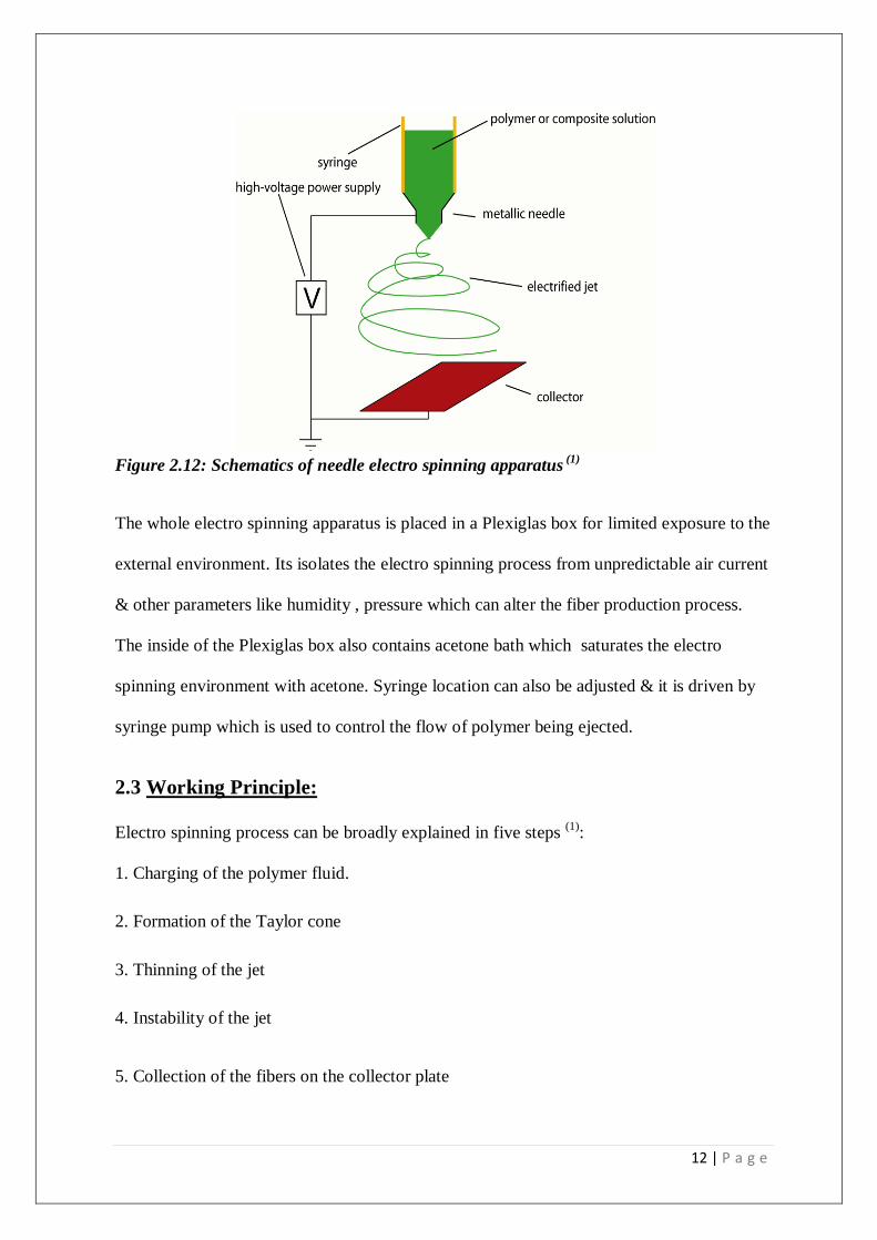
Figure 2.12: Schematics of needle electro spinning apparatus (1)
The whole electro spinning apparatus is placed in a Plexiglas box for limited exposure to the
external environment. Its isolates the electro spinning process from unpredictable air current
& other parameters like humidity , pressure which can alter the fiber production process.
The inside of the Plexiglas box also contains acetone bath which saturates the electro
spinning environment with acetone. Syringe location can also be adjusted & it is driven by
syringe pump which is used to control the flow of polymer being ejected.
2.3 Working Principle:
Electro spinning process can be broadly explained in five steps (1)
:
1. Charging of the polymer fluid.
2. Formation of the Taylor cone
3. Thinning of the jet
4. Instability of the jet
5. Collection of the fibers on the collector plate
13 | P a g e
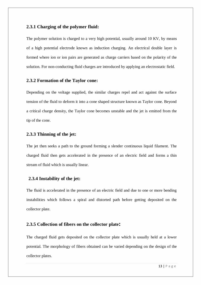
2.3.1 Charging of the polymer fluid:
The polymer solution is charged to a very high potential, usually around 10 KV, by means
of a high potential electrode known as induction charging. An electrical double layer is
formed where ion or ion pairs are generated as charge carriers based on the polarity of the
solution. For non-conducting fluid charges are introduced by applying an electrostatic field.
2.3.2 Formation of the Taylor cone:
Depending on the voltage supplied, the similar charges repel and act against the surface
tension of the fluid to deform it into a cone shaped structure known as Taylor cone. Beyond
a critical charge density, the Taylor cone becomes unstable and the jet is emitted from the
tip of the cone.
2.3.3 Thinning of the jet:
The jet then seeks a path to the ground forming a slender continuous liquid filament. The
charged fluid then gets accelerated in the presence of an electric field and forms a thin
stream of fluid which is usually linear.
2.3.4 Instability of the jet:
The fluid is accelerated in the presence of an electric field and due to one or more bending
instabilities which follows a spiral and distorted path before getting deposited on the
collector plate.
2.3.5 Collection of fibers on the collector plate:
The charged fluid gets deposited on the collector plate which is usually held at a lower
potential. The morphology of fibers obtained can be varied depending on the design of the
collector plates.

14 | P a g e
2.4 Factors Affecting Electro spinning:
The electro spinning process is affected by various parameters. Broadly, it can be classified
into three different categories:
2.4.1 Polymer Solution Parameters
a) Molecular weight & solution viscosity
b) Surface tension
c) Solution conductivity
d) Dielectric constant of the solvent
e) Volatility of the solvent
2.4.2 Electric Field Parameters:
a) Applied electric potential
b) Feed rate of the solvent
c) Diameter of the orifice of the needle
d) Effect of the collector plate
e) Distance between the tip and collector
2.4.3 Environmental parameters:
a) Temperature
b) Humidity
c) Air velocity inside the chamber
2.5 Recent Development in the Electro spinning approach:

15 | P a g e
Daming Zhang and Jiang Chang et. al [1] has demonstrated that nanofibers can be uni -
axially aligned by introducing insulating gaps into conductive collectors. However these
mats were 2-D membrane. Rotating collectors can be used to collect 3-D nanofibres the
limitations have to be considered to collect 3-D template. It is a unique static collecting
method with combinatorial electric fields. It is based on manipulation of electric field and
electric forces. Basically here collector was divided as working collector & as assistant
collector. The different collector configurations was used to alter the electric field and also
to expand the deposition areas of the fibers & in this was way prohibiting the convergent
deposition of the fiber at the top. Furthermore another stick collector was introduced to
avoid inhomogeneous collection of fibers at the root of previous collector. In summary 3-D
collection of electro spun fibers is a versatile technique to fabricate fibrous tubes which can
be used in various industrial & biomedical applications. For achieving all these desired
results different process parameters as well as solution parameters have to be considered
well enough. Stefania Pagliari et.al [2] A novel method of electro spinning was developed to
fabricate multistage three dimensional scaffolds with a controlled architecture of fiber
diameters and which is useful towards soft tissue engineering. A series of Poly (e-
caprolactone) (PCL) solutions were prepared of different polymer concentrations and were
electro spun under different process parameters to determine the optimal conditions to
obtain reproducible nano- and microfibers. The resulting materials finely mingle nano- and
micro scale fibers together. A detailed proof was conducted on the concept on a simpler
bimodal PCL scaffold with fiber distribution at 600 nm and 3.3 nm. Three conventional
unimodal scaffolds with mean diameters of 300 nm and 2.6 and 5.2 nm, respectively, were
used as controls to evaluate the new materials. The fiber diameter was also controlled and so
was the beads formation and the fibers was found to accelerate cell adhesion and
proliferation.

16 | P a g e
Jha B. S. et. al. [3] fabricated 3-D nerve fibers using the air-gap electro spinning process
where PCL dissolved in Tetra fluoro ethanol (TFE) at various concentrations and the
solutions were injected into 10ml syringe. Several electro spinning concentrations were
tested at different concentrations of PCL. The setup used in this process consists of two
vertical piers which are grounded to a common voltage, usually set at -4.0 to -16.0 kV. The
additional set of the horizontal piers arise from each vertical pier inwards at right angle. A
gap separates the terminal end of these projecting piers & the solutions were charged to +22
kV & are directed into the gap separating the horizontal pier which was grounded. The feed
rate was kept at 2-20 ml/hr & the distance to tip collector was varied up to 10 cm – 30 cm.
And finally the polymer jet stream reaches the target resulting in the formation of bundle of
parallel fiber arrays. These fibers were used in the nerve reconstruction process as in case of
nerve injury and nerve tissues. According to Selcuk Comlekci et. al [4], the controlled
electric field is used to create charged jet of polymer solutions. While the jet is travelling in
the air evaporation of solvent occurs leaving behind a charged fiber which was electrically
deflected or collected on the metal screen. The study shows that a positive potential was
applied to the polymer blend solution by insertion of a copper wire into the glass pipette
with the collection screen placed 25 cm horizontally from the tip of the pipette.

17 | P a g e
3. MATERIALS AND METHODS
3.1: Various collector designs available:
Different collector Designs in Electro spinning are
(i) Square Plate Collector :
We have already seen a collector of this type.
(ii) Rotating Drum Collector:
Figure 3.11: Rotating Drum collector schematics (2)
The process makes use of electrostatic and mechanical force to spin fibers from the tip of a
fine orifice or spinneret. The spinneret is maintained at positive or negative charge by a DC
power supply. When the electrostatic repelling force overcomes the surface tension force of
the polymer solution, the liquid spills out of the spinneret and forms an extremely fine
continuous filament.

18 | P a g e
(iii) Two pole air gap electro spinning (3)
:
Helps in fabrication of highly aligned 3-dimensional scaffolds. Air-gap electro spinning
utilizes the charging of the spinneret of the polymer solution which is placed at equal from a
pair of conductive parallel targets. The effect of the electro spinning jet’s splitting is due to
the electric field. The charge of the individual fibers creates a mutual repulsion, which
enhances their ability to align and be distributed evenly. Using this method, the electro spun
scaffold obtained is similar in both overall size and shape as the parallel collecting
electrodes. Thus, the shape of the scaffold can be altered by changing the profile of the
electrodes.
Figure 3.12: Schematic dig. Of two pole air gap type collector
(3)
3.2: Materials used –
(a) Electro spinning machine (El Marco NS-200, Czech Republic)
(b) Poly-Vinyl Alcohol (PVA) Solution.
(c) Aluminium foil
(d) Syringe needle along with its cap.

19 | P a g e
(e) Plastic Cylindrical long hollow tube open at both ends.
(f) Electric motor
(g) Two beakers of required 50 ml capacity with stirrer.
(h) Weighing balance
(i) Forceps
3.2.1: Basics of electro spinning Machine used:
Figure 3.13: Electro spinning machine
The Electro spinning machine currently used in this process has the brand name as “El
Marco NS LAB -200” manufactured in Czech Republic. The collector design used in this
project consisted of rolling cylinder type model. When the machine is in a working
condition, the voltage in the process can be varied between 0 – 80 kV. This voltage
alternating is there to differentiate the type of fibers to be generated.
20 | P a g e
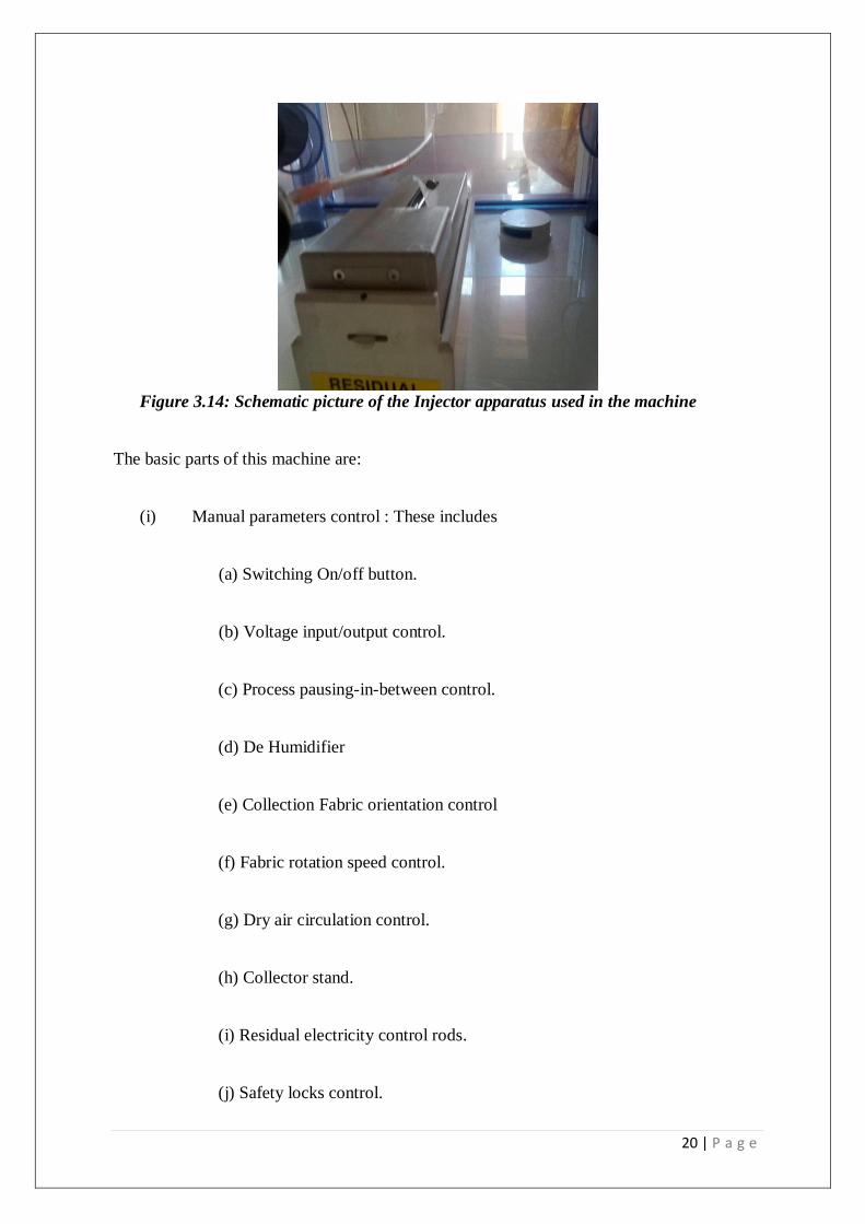
Figure 3.14: Schematic picture of the Injector apparatus used in the machine
The basic parts of this machine are:
(i) Manual parameters control : These includes
(a) Switching On/off button.
(b) Voltage input/output control.
(c) Process pausing-in-between control.
(d) De Humidifier
(e) Collection Fabric orientation control
(f) Fabric rotation speed control.
(g) Dry air circulation control.
(h) Collector stand.
(i) Residual electricity control rods.
(j) Safety locks control.

21 | P a g e
(ii) Injection part : These includes
(a) Rolling Horizontal cylinder.
(b) Cuboidal Box.
(c) Space for Polymer solution.
(iii) Collection Part:
(a) Rolling cylindrical Collector.
(b) Rotating Fabric.
3.2.2 Polymer Used: PVA is used for the preparation of polymer solution whose various
parameters are listed below:
Concentration of the PVA: 15 % by weight
Viscosity of the polymer solution: ƞ0 = 1.194
The viscosity of the polymer solution by using viscometer with results is shown below:
Figure 3.15: Software reading of instrument used to determine viscosity by taking 30
readings starting from zero shear stress to infinite stress.

22 | P a g e
3.2.3: Processing of the electro spinning Machine:
After filling the box, the machine is locked properly by ensuring the safety lock control
activated. The machine is then started by Switching on the De Humidifier first attached to
the main machine, first, to completely evacuate any humidity or moist air inside the setup.
For more safety measures, dry air is blown inside the system to eliminate any left behind
humidity. This is done because the voltage between the collector and the injector is very
high and thus a spark can be produced due to moist air presence which can create a
disturbance in the collection process.
Now next step is the Switching On of the process by setting the input voltage through
voltage control unit. This step takes about 10-20 minutes for the collection process of the
fibers. Due to high voltage difference between the injector and the collector, the polymer
solution gets charged up. This machine works on the principle of “collection of fibers in
antigravity direction”.
3.2.4: Collection and removal of Fibers
After 10-20 minutes of switching on of the machine, the Nano fibers scaffold is collected on
the fiber above injector which is at Zero Potential. These fibers generated are then scrapped
off by using Physical or Chemical methods from the fabric and Nano-Fibers sheets are thus
obtained.
Now this particular electro spinning process can only generate 2-D fibers which are in the
form of a sheet. However, we changed the various process parameters, the strength of fibers
can be changed, alignment of fibers can be changed but we can’t alter the dimension of the
fiber that is the fiber collected on the fabric will be in the shape of a sheet only. It cannot be
in a three dimensional structure.

23 | P a g e
3.3: Idea of 3-D generation of Nanofibres by using The Electro
spinning Machine:
By visualizing the process/Mechanism followed for Nanofibre generation, we came up with
a conclusion that some setup alteration can be done in between the distance of the collector
and the injector to generate 3-D Nanofibres. The approaches that can be followed are:
(I) Surface Modification of the fabric where fibers are deposited.
(II) Using alternate collection setup in the space between the injector and the
fabric to acquire the 3-D structure.
3.3.1: Early Development phases:
3.3.1.1 Basic Design:
Figure 3.16: CATIA Generated model of collector design (4)
This design is called as “3-D columnar collector” (4)
. This collector design consists of two
parts: (A) Square base: Made up of any conducting material like Aluminium, Silver,
Stainless Steel, Iron etc. The conducting surface of this part is taken as some
fibers will also get deposited on this part. So it should be conducting in order to
account for efficient deposition on the base.

24 | P a g e
(B) Needle projection perpendicular to the base: This part of this collector is made
up of similar conducting material that of the square base. Length of around 10-15
cm long, depending on the amount of the required fiber its length can be adjusted.
It is fixed to the square base perpendicularly in a manner that it projects out from
the plane of the base. The needle should be pointed at the top as it will have
Electric field which will carry on the required deposition process. The needle is
then coated with any Non conducting shape to get our desirable shape that will be
suitable for 3D structure.
3.3.1.2: Procedure followed:
Stage 1: Aluminium sheet is taken which acted as a square base of this design. This
aluminium sheet was then attached to the fiber collection Fabric. Now, the machine in use
has Injector downwards and collector on the top, which is the fiber deposition, is
antigravity, therefore the aluminium was fixed on the base of the fabric.
Stage 2: Stainless steels syringe needle was taken to act as a needle part of the design and
was fixed to the aluminium base in an upside down manner. That is, the whole collector
design here is used in an inverted manner. The syringe cap which covered the needle acted
as a shape giving non conductor to the fiber deposited.
Stage 3: Fix the fabric by not allowing it to rotate so that modified surface of the fabric only
comes in play in the electro spinning procedure.
Stage 4: The fiber generation took place around the cap but a conical shape deposition was
obtained instead of cylindrical shape.

25 | P a g e
Figure 3.17: Conical shaped fibers deposition by using the given approach
Figure 3.18: Fiber obtained from the above approach. The fibers obtained are
obtained in the shape of an umbrella which is closed; not completely a 3-D structure
The reason behind this was:
(i) The gap between the cap height and the fabric surface was covered up by the
fibers coming from the injector.
(ii) The dry air blowing inside the machine during the process which deviated the
fibers away from the cylindrical cap due to which a conical type structure was
obtained.

26 | P a g e
So, important parameters which required a change in first design to get the modified
design are:
(a) No use of Square base: There is no particular use of the square base as the main
deposition area was around the needle. Therefore, square base is not at all required in
generating 3-D.
(b) Less concentration to the fibers deposited: There was no setup which existed to
guide the fibers to get deposited around the cylindrical cap. As a result, it deposited
around the area of the cap results in a conical shaped fiber. So, a guider was
required.
(c) Removal of the Nanofibres form the collector base: It’s very difficult to remove
the deposited nanofibre from the setup. As a result, the fibers we got were very weak
and can’t be counted in as a 3D structure.
3.4: Modification of the collector:
“Suspended Rolling Cylindrical based deposition of Nanofibres “:
27 | P a g e
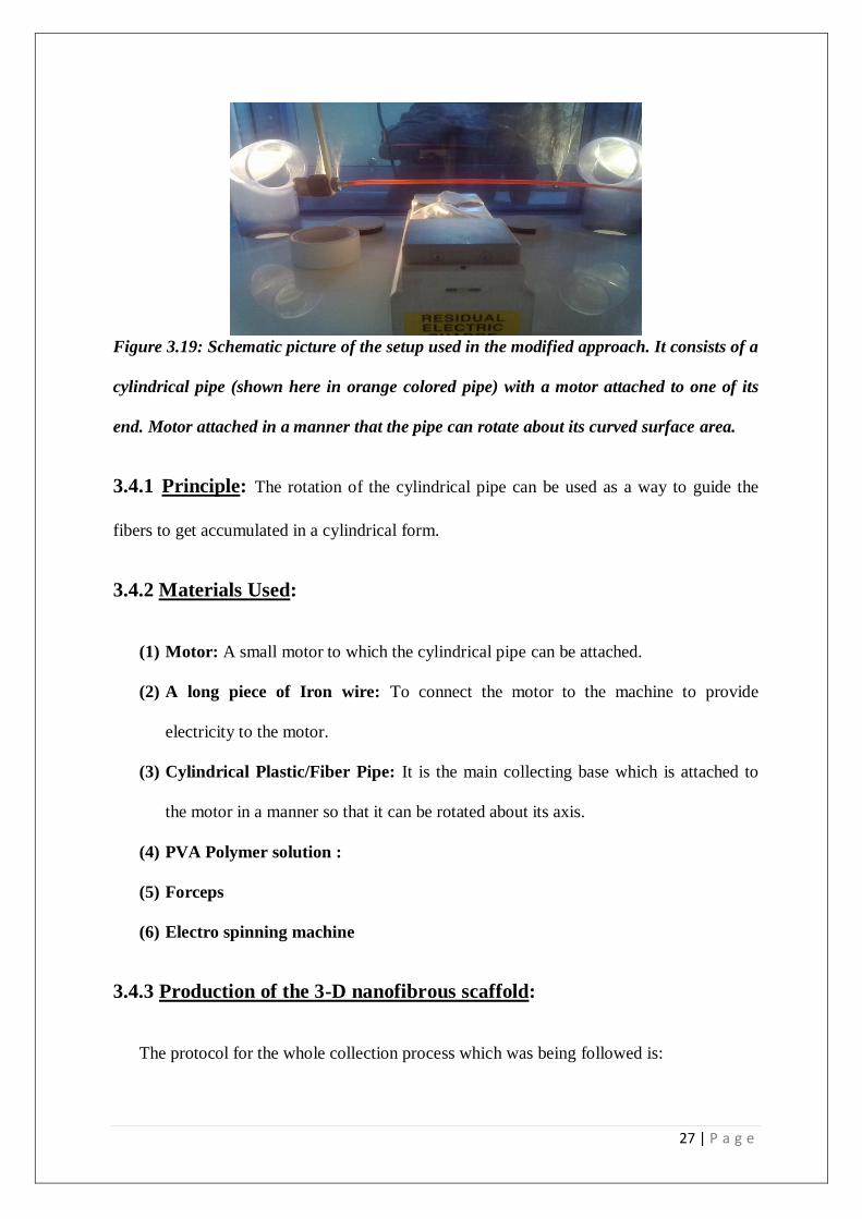
Figure 3.19: Schematic picture of the setup used in the modified approach. It consists of a
cylindrical pipe (shown here in orange colored pipe) with a motor attached to one of its
end. Motor attached in a manner that the pipe can rotate about its curved surface area.
3.4.1 Principle: The rotation of the cylindrical pipe can be used as a way to guide the
fibers to get accumulated in a cylindrical form.
3.4.2 Materials Used:
(1) Motor: A small motor to which the cylindrical pipe can be attached.
(2) A long piece of Iron wire: To connect the motor to the machine to provide
electricity to the motor.
(3) Cylindrical Plastic/Fiber Pipe: It is the main collecting base which is attached to
the motor in a manner so that it can be rotated about its axis.
(4) PVA Polymer solution :
(5) Forceps
(6) Electro spinning machine
3.4.3 Production of the 3-D nanofibrous scaffold:
The protocol for the whole collection process which was being followed is:

28 | P a g e
(1) Cylindrical plastic pipe was attached to the motor as seen in Fig 3.19.
(2) The whole setup was suspended in region of the collector and the injector in a
manner such that the axis of the pipe was parallel with the rolling cylinder of the
injector.
(3) PVA solution was taken with the required Dynamic Viscosity of ƞ0 = 1.194 as
measured by Viscometer by using 30 iterative reading.
(4) After completing the setup for the machine to work, the cylindrical pipe was made
to rotate at lower angular speed about its axis and the fiber started depositing on the
surface.
(5) The deposition took place for 15-20 minutes and after that, the fiber which got
deposited on the circumference of the cylindrical pipe was scrapped off
mechanically by using forceps after 20-30 minutes of the completion of the whole
process.
3.4.4: SCANNING ELECRTION MICROSCOPE (SEM) ANALYSIS:
The nanofibrous scaffolds are than studied under SEM to study the surface morphology.

29 | P a g e
3.4.5 Images during the deposition process:
Figure 3.20: Schematic image of the electro spinning process going on with
the cylindrical pipe rotating with the help of the motor. The fibers get deposited on
cylindrical pipe.
Figure 3.21: Motor with the cylindrical pipe

30 | P a g e
Figure 3.22: Fibers deposited after 10-20 minutes of the process on the curved area

31 | P a g e
4: RESULTS AND DISCUSSIONS
4.1 3-D Nano-Fibers Obtained from the experiment:
The nanofibres obtained from these fibers were cylindrical in shape and hollow from inside.
After the deposition on the surface of the curved surface area of the pipe by mechanically
scrapping it off the surface by using forceps.
Figure 4.11:Cylindrical nanofibrous scaffolds

32 | P a g e
4.2: SEM ANALYSIS:
The fibers thus obtained were then studied under Scanning Electron Microscopy to view the
surface and the material properties of the hollow cylinder obtained. The results obtained are:
Figure 4.12: schematic diagram shown nano fiber surface magnified for 100 times
The visible property from the above image is that the fiber deposition is Random. It is
not aligned.
Figure 4.13: At magnification of 750 times

33 | P a g e
The above SEM image confirms that the fibers we got are not aligned fibers. Therefore, the
result at what we saw in figure 4.11 is being established by conforming it at 750
magnifications.
Now to check for the bead formation:
Figure 4.14: Schematic Diagram showing the absence of Bead formation.
It is clearly visible from the above SEM image that there is negligible bead form and the
fiber deposition is continuous.
Figure 4.15: schematic Diagram showing the fibers diameter.

34 | P a g e
The diametric values of various constituent fibers, generally ranging from 1.50 µm –
2.60 µm show that there is a very fine deposition in the range of 100-1000 nm. The reason
for this observation is the variation of the distance of the rotating cylindrical collector from
the Injector that’s why they are in micrometer range.
Figure 4.16: schematic diagram at 3500 magnification
Figure 4.17: schematic diagram showing the cylindrical nanofibre opening

35 | P a g e
Figure 4.18: schematic diagram showing the other opening of the hollow cylinder
Figure 4.19: opening with dimensions
SEM results here show that there is a random fiber deposition

36 | P a g e
4.3: DESCRIPTION OF THE MECHANISM OF NANOFIBRES
FORMATION
The mechanism which works here for the fiber deposition is based on the principle of fiber
deposition in a shape due to the rotation of the cylindrical pipe.
As the charged up polymer solution is injected from the injector, it meets the rotating
cylindrical pipe in between. The Rotating cylinder guides the fibers to get deposited around
its curved surface area in a random manner.
As the pipe is held in a manner such that its axis is parallel to the rotating cylinder of the
injector, so the fibers are deposited along the whole curved surface area. The cylinder was
made to rotate at a very low speed, so the deposition resulted in a random manner.
The directionality of the charged fluid flow is altered by the Rotating cylinder.
There were many factors which determined the fiber generation. They are:
(i) Angular speed of the cylindrical pipe: The angular speed of the rotating
cylinder has got a very great role to play in the alignment of the fibers. Greater is
the angular speed, more is the aligned fibers.
(ii) Velocity of the Air flow inside the column: The wastage of the nanofibres can
also be controlled by optimizing the dry air flowing inside the column. The air
tends to drive away the fibers at the ends of the cylinder thus leading to fiber
deposition at the ends. Thus by lowering the air speed, we can eliminate its
wastage.
(iii) Surface area of the injecting column: The surface area of the injecting column
is very large due to which the fiber deposition is not concentrated at a particular
region.

37 | P a g e
(iv) Distance of the cylindrical pipe from injector: By altering the cylindrical
pipe’s distance from the injector we can optimize the fiber deposition which will
affect the strength of the fibers deposited.
(v) Concentration of the solution used: The polymer solution used in the
experiment is PVA whose concentration was 10% and 15% by weight when
dissolved in water. By altering the concentration of the polymer, optimized and
the desired fibers can be generated.
(vi) Type of the polymer used: Instead of PVA, silk, PLLA, PLC, etc. can be used
which are more efficient during scrapping off the fiber from the depositor as they
are insoluble in polar solvents.
38 | P a g e
5. CONCLUSION
By using this method, thus three dimensional Nano fibers were generated of cylindrical
shape which was hollow from inside of acceptable strength as it walls thickness is in a
millimeter range. The combination of electrical force with the angular force of the
cylindrical pipe proves to be a very effective way to generate Nanofibres of cylindrical
shape. So, 3D Nanofibres are possible to be generated by using this electro spinning
machine.
By using a cylindrical pipe, cylindrical fibers were generated. By using various other
rotating structures in the space between the injector and the collector, various desired shapes
and sizes; three dimensional nanofibres can be generated.
The nanofibres generated from this approach were cylindrical in nature which can further be
used for various experimental studies. Such as:
(i) Vascular blood vessels implants
(ii) Effective cell culturing environment
The future aspects cover designing of electro spinning machines with arrangements for both
two dimensional and three dimensional fibers formation.
Finally, this novel approach is cost effective and flexible as various other rotating shapes in
the machine’s vicinity can be used to generate various other shapes and sizes oriented three
dimensional Nanofibres.

39 | P a g e
REFERENCES
1. Rout Saroj Kumar; “Design of Digital thermometer and application in Electro
spinning; e-thesis; NIT Rourkela (2011); 9-12.
2. www.nabond.com/electrospinning.html
3. Garg Koyal and Bowlin Gary L.; “Electro spinning jets and nanofibrous
structures”; BIOMICROFLUIDICS 5, 013403 (2011), Page No. 13, Fig. 11; .
4. Zhang Daming and Chang Jiang; “Electro spinning of three dimensional
Nanofibrous tubes with controllable architecture; Nano letters, Vol.8. No.10
*(2008) ; Page no : 3284
5. Reneker DH, Chun I. “Nanometer diameter fibers of polymer produced by
electro spinning”, (1996); 7; 216-23.
6. Bognitzki M, Wendorff JH, Greiner A. “Sub micrometer shaped polylctide fibers
by electro spinning”. Polymer prep. (ACS, PMSE) 2000; 82:115-6.
7. Warner SB Buer A, Ugbolue SC, Ruteldge GC, Shin MY. M98-D01, “A
fundamental investigation of the formation and properties of electro spun
fibers”. Department of Textile Sciences, University of Massachusetts Dartmouth;
Department of chemical Engg. And Material sciences, Massachusetts Institute of
Technology Cambridge, 2000.
8. Coles Stuart R, Jacobs Daniel k, Meredith James O, Barker Guy, Clark Andrew
J, Kirwan Kerry, Stanger Jon, Tucker Nick; “A design of experiments (DOE)
approach to material properties optimization of electro spun fibers”, doi:
10.1002/app.32022.
9. Cardinal Halloran Kristen O’, Wong Steffi, “An investigation of process
parameters to optimize the fibers diameters of electro spun vascular scaffolds
through experimental design”; ENGR 462, Fall 2010 .