ProE_Tutorial2 Variable Section Sweeps
7
AE 440A Pro/E Tutorial 2: Variable Section Sweeps In the last P roE class, you were taught to create a blended protrusion. As you no doubt learned from the homework assignment, a blend is not the best method of creating a complicated shape. Here, you will be taught how to use the variable section sweep tool. The variable section sweep is a tool that will allow you to control the shape of your fuselage in a far more practical manner than using a single blend. Variable Section Sweep: Variable section sweeps allow you to create solids that are particularly useful when modeling fuselages. There are many ways to create a variable section sweep body, and today’s tutorial will demonstrate only one such method. There are probably faster ways to perform some of the functions, and many other functions will be skipped over. You are encouraged to experiment when doing the next homework assignment. 1. As a general tip, it is a good idea to change your working directory before creating a new part. That way, you know for sure where all your files are saved. Create a new part file in PRO/E. 2. When doing a variable section sweep, you are going to have to define a number of so- called trajectories (don’t do anything yet): • The origin trajectory – for this, you can use a straight line down the length of your fuselage. • The X-trajectory – this defines your first trajectory and also how the section is varied. You can use the line that defines the bottom of the fuselage for this. • The 4 trajectories that define the shape of the fuselage bottom, left side, top and right side. 3. After the trajectories are defined, you will be asked to define a section. The section determines what the cross-section along your body will look like. All the trajectories (but not the section) can be sketched as you define the variable section sweep body, or they can be defined beforehand. We will pre-define them in this tutorial, but feel free to experiment when you do the homework. 4. First we will define all the trajectories in the vertical plane: the center axis of the fuselage, the curve defining the bottom of the fuselage and the curve defining the top. Click on the “Sketch tool” button: 5. Click on the “Right” plane in the window. Click on “Sketch”. When the “References” window comes up, you can select “Close”. You should now be in the sketcher window. 6. Start by drawing a straight line for the longitudinal axis of the aircraft. Use the line tool (second from the top on the right-hand toolbar). Draw the line by clicking on the horizontal axis to the left and to the right of the vertical axis, and then finish the line by clicking the center mouse button. Two dimensions should automatically appear above the line. Use the selection tool (top button on the sketching toolbar) to select the dimensions and change the values so that the line extends 250 inches to the left
-
Upload
jorge-luis -
Category
Documents
-
view
224 -
download
0
Transcript of ProE_Tutorial2 Variable Section Sweeps
7/31/2019 ProE_Tutorial2 Variable Section Sweeps
http://slidepdf.com/reader/full/proetutorial2-variable-section-sweeps 1/7
AE 440A
Pro/E Tutorial 2: Variable Section Sweeps
In the last ProE class, you were taught to create a blended protrusion. As you no doubtlearned from the homework assignment, a blend is not the best method of creating a
complicated shape. Here, you will be taught how to use the variable section sweep tool.The variable section sweep is a tool that will allow you to control the shape of yourfuselage in a far more practical manner than using a single blend.
Variable Section Sweep:
Variable section sweeps allow you to create solids that are particularly useful when
modeling fuselages. There are many ways to create a variable section sweep body, andtoday’s tutorial will demonstrate only one such method. There are probably faster ways to
perform some of the functions, and many other functions will be skipped over. You are
encouraged to experiment when doing the next homework assignment.
1. As a general tip, it is a good idea to change your working directory before creating a
new part. That way, you know for sure where all your files are saved. Create a newpart file in PRO/E.
2. When doing a variable section sweep, you are going to have to define a number of so-
called trajectories (don’t do anything yet):
• The origin trajectory – for this, you can use a straight line down the length of
your fuselage.
• The X-trajectory – this defines your first trajectory and also how the section isvaried. You can use the line that defines the bottom of the fuselage for this.
• The 4 trajectories that define the shape of the fuselage bottom, left side, top
and right side.3. After the trajectories are defined, you will be asked to define a section. The section
determines what the cross-section along your body will look like. All the trajectories
(but not the section) can be sketched as you define the variable section sweep body,
or they can be defined beforehand. We will pre-define them in this tutorial, but feelfree to experiment when you do the homework.
4. First we will define all the trajectories in the vertical plane: the center axis of the
fuselage, the curve defining the bottom of the fuselage and the curve defining the top.
Click on the “Sketch tool” button:
5. Click on the “Right” plane in the window. Click on “Sketch”. When the
“References” window comes up, you can select “Close”. You should now be in the
sketcher window.6. Start by drawing a straight line for the longitudinal axis of the aircraft. Use the line
tool (second from the top on the right-hand toolbar). Draw the line by clicking on the
horizontal axis to the left and to the right of the vertical axis, and then finish the lineby clicking the center mouse button. Two dimensions should automatically appear
above the line. Use the selection tool (top button on the sketching toolbar) to select
the dimensions and change the values so that the line extends 250 inches to the left

7/31/2019 ProE_Tutorial2 Variable Section Sweeps
http://slidepdf.com/reader/full/proetutorial2-variable-section-sweeps 2/7

7/31/2019 ProE_Tutorial2 Variable Section Sweeps
http://slidepdf.com/reader/full/proetutorial2-variable-section-sweeps 3/7
Select “Flip” to change the direction (the arrow should be pointing down), and thenclick “Sketch.” Click “Close” on the References window.
11. First we will define a symmetry axis. Select the “Centerline” tool by first clicking the
arrow next to the line tool (second button from the top). The picture on the button willchange to the one shown below:
Draw a centerline directly on the vertical axis in the window. When you are done,click the middle mouse button.
12. Now draw the right side of the fuselage (left of the vertical). Remember to edit the
dimensions so it extends again 250 in. to the front and 500 in. to the rear of the
horizontal line. You should have something like the drawing shown below (feel freeto use a simpler shape):
13. Finally we need to mirror the right side of the fuselage to the left. Do this by first
selecting the curve that we just drew with the selection tool. Now click on the mirrorbutton (the one just above the check mark button). Finally, click on the center line
that we drew earlier (the vertical line in the sketch). You should end up with the

7/31/2019 ProE_Tutorial2 Variable Section Sweeps
http://slidepdf.com/reader/full/proetutorial2-variable-section-sweeps 4/7
following sketch:
14. Now click on the button with the check mark. If you select “Standard Orientation”
under the “View” menu, you should now have something like this:

7/31/2019 ProE_Tutorial2 Variable Section Sweeps
http://slidepdf.com/reader/full/proetutorial2-variable-section-sweeps 5/7
15. It may be a good idea to save your part at this point. We now have everything neededto create the variable section sweep body. Select “Insert >> Variable Section
Sweep.” Click “Sweep as solid” button on the bottom of the screen.
16. Click on the “References” button on the bottom of the screen. Click on the straightcenterline axis that you drew earlier. You should have “Normal to Trajectory,”
“Automatic,” and “Default” as the options shown on the drop down menus.17. Next you will define the X-Trajectory. As mentioned earlier, you should use thecurve that defines the lower surface of the fuselage as your X-Trajectory. So, click
on “Details…” and the “Chain” window will appear. Click “Add” in the “Chain”
window and click on the bottom of the fuselage. Click “Okay” in the “Chain”
window. Click the X-box next to Chain1 in the “References” at the bottom of thescreen.
18. Now we have to select the four curves that define the lower, right-hand, upper and
left-hand side of the fuselage in that order. Click “Details…” again. Click “Add” andclick on the bottom of the fuselage again. Click “Add” and click on the right side of
the fuselage.
19. Continue this process until you selected all four fuselage curves.20. Click on the “Create or edit sweep section” button on the bottom of the screen. You
will now see the front view of your fuselage. You can simply use a spline that
connects the four points that define the front of your fuselage (the points should bemarked with “x” symbols). This is what my cross-section looked like after I drew the
spline:
7/31/2019 ProE_Tutorial2 Variable Section Sweeps
http://slidepdf.com/reader/full/proetutorial2-variable-section-sweeps 6/7
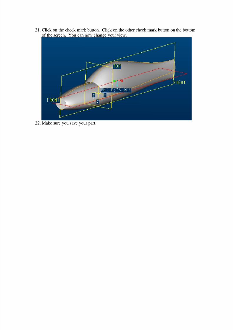
21. Click on the check mark button. Click on the other check mark button on the bottomof the screen. You can now change your view.
22. Make sure you save your part.

7/31/2019 ProE_Tutorial2 Variable Section Sweeps
http://slidepdf.com/reader/full/proetutorial2-variable-section-sweeps 7/7
Some helpful hints for creating a drawing.
1. Open your part before creating a drawing. That way your part should be the default
model.2. When selecting a new drawing, use the “Empty with format” option and browse to
select “a.frm.”3. To show your drawing on the sheet, use “Insert >> Drawing View >> General” andthen click on the sheet. Your model will appear along with the “Drawing View”
Window. In this window you can change the view type, scale, etc.
4. Use “Insert >> Drawing View >> Projection” to make the other views.
5. You can use “View >> Show and Erase” for dimensions.6. You can use “Insert >> Note” to insert text.