ProECU Nissan GT-R - Zendesk · used on high power cars with catalysts removed. Setting all the...
96
ProECU Nissan GT-R Tuning Guide 2008-onward Model Year v1.70
Transcript of ProECU Nissan GT-R - Zendesk · used on high power cars with catalysts removed. Setting all the...

ProECU Nissan GT-R
Tuning Guide
2008-onward Model Year
v1.70

Page 2
Contents 1. ECU Map Descriptions.............................................................................................................. 5
1.1. Fuel Control ....................................................................................................................... 5 1.2. Ignition Control .................................................................................................................. 8 1.3. Boost Control ................................................................................................................... 10 1.4. Intake VVT ....................................................................................................................... 11
1.5. Accel Pedal and Throttle Angle ....................................................................................... 11 1.6. Torque Maps ................................................................................................................... 12 1.7. Airflow Sensor Scaling and Engine Load ......................................................................... 12 1.8. Fuel Pump Control ........................................................................................................... 13 1.9. Idle Control ...................................................................................................................... 14
1.10. Sensor Scaling ............................................................................................................. 14 1.11. Limiters ........................................................................................................................ 15
1.12. Diagnostic Trouble Codes ............................................................................................ 15
2. RaceROM Overview ............................................................................................................... 16 2.1. RaceROM Features ......................................................................................................... 16
2.1.1. Map Switching .......................................................................................................... 16 2.1.2. RaceROM Boost Controller ...................................................................................... 16
2.1.3. RaceROM Launch Control ....................................................................................... 17 2.1.4. RaceROM Rolling Launch ........................................................................................ 17
2.1.5. RaceROM Valet Mode .............................................................................................. 17 2.1.6. RaceROM Knock Warning ....................................................................................... 17
2.1.7. Boost Target ............................................................................................................. 17
2.1.8. Per Gear Boost Control ............................................................................................ 17
2.1.9. Upshift Boost Spike Prevention ................................................................................ 17
2.1.10. Boost Limit Maps ...................................................................................................... 17
2.1.11. Per Gear Rev Limits ................................................................................................. 18
2.1.12. Large Fuel Injector Support ...................................................................................... 18
2.1.13. MAF Bank Switching ................................................................................................ 18 2.1.14. Speed Density - VE Based ....................................................................................... 18
2.1.15. Extended Maps ......................................................................................................... 18 2.1.16. Simplified Ignition Timing .......................................................................................... 18
2.1.17. Boost Gauge Rescaling ............................................................................................ 18 2.1.18. Custom Parameter Logging ...................................................................................... 18
2.1.19. Custom Maps ........................................................................................................... 19
3. RaceROM Configuration ......................................................................................................... 20 3.1. Map Switching Feature .................................................................................................... 20
3.1.1. Method of Operation ................................................................................................. 20 3.1.2. Switching between modes ........................................................................................ 20
3.1.3. Integration with Per Gear Boost Control Feature ...................................................... 20 3.1.4. Integration with RaceROM Boost Controller (RBC) Feature ..................................... 20
3.1.5. Integration with Per Gear Rev Limits Feature ........................................................... 20 3.1.6. Integration with Large Fuel Injectors Feature ........................................................... 20
3.1.7. Related Maps ........................................................................................................... 20
3.2. RaceROM Boost Controller (RBC) Feature ..................................................................... 22 3.2.1. Method of Operation ................................................................................................. 22 3.2.2. Configuration ............................................................................................................ 22
3.2.3. Related Maps ........................................................................................................... 22
3.3. Boost Gauge Rescaling ................................................................................................... 23 3.4. Per Gear Boost Control Feature ...................................................................................... 23
3.4.1. Method of Operation ................................................................................................. 23

Page 3
3.4.2. Integration with Map Switching Feature .................................................................... 23 3.4.3. Related Maps ........................................................................................................... 23
3.5. RaceROM Launch Control (RRLC) .................................................................................. 24 3.5.1. Method of Operation ................................................................................................. 24 3.5.2. Related Maps ........................................................................................................... 24
3.6. RaceROM Rolling Launch (RRRL) .................................................................................. 25 3.6.1. Method of Operation ................................................................................................. 25 3.6.2. Related Maps ........................................................................................................... 25
3.7. Large Fuel Injector Support ............................................................................................. 26 3.7.1. Method of Operation ................................................................................................. 26 3.7.2. Related Maps ........................................................................................................... 26
3.8. Upshift Boost Spike Prevention Feature .......................................................................... 26 3.8.1. Method of Operation ................................................................................................. 26
3.8.2. Related Maps ........................................................................................................... 27
3.9. Per Gear Rev Limits Feature ........................................................................................... 27 3.9.1. Method of Operation ................................................................................................. 27
3.9.2. Integration with Map Switching Feature .................................................................... 27 3.9.3. Related Maps ........................................................................................................... 28
3.10. Visual Knock Warning Feature ..................................................................................... 28 3.10.1. Method of Operation ................................................................................................. 28
3.10.2. Related Maps ........................................................................................................... 28
3.11. Alternative IAT Sensor Scale ....................................................................................... 28 3.11.1. Related Maps ........................................................................................................... 28
3.12. MAF Bank Switching Feature ....................................................................................... 28 3.12.1. Method of Operation ................................................................................................. 28 3.12.2. Related Maps ........................................................................................................... 28
3.13. Speed Density Feature ................................................................................................ 29 3.13.1. Method of Operation ................................................................................................. 29
3.13.2. Removal of MAF sensor (optional) ........................................................................... 29
3.13.3. Using Speed Density and MAF sensor together ....................................................... 29 3.13.4. Related Maps ........................................................................................................... 30
3.14. RaceROM Valet Mode ................................................................................................. 30 3.14.1. Method of Operation ................................................................................................. 30
3.14.2. Related Maps ........................................................................................................... 30
3.14.3. Configuration ............................................................................................................ 31
4. Tuning Advice - Ignition .......................................................................................................... 32 4.1. Ignition Control Mode 1 to Mode 4 ................................................................................... 32 4.2. Dynamic Advance Gen 2 models .................................................................................... 32 4.3. Coolant Temp display during Map Switch ........................................................................ 33
4.3.1. Intake Air Temp compensation ................................................................................. 34
5. Tuning Advice - Fuel ............................................................................................................... 35
5.1. Fuel Trims ........................................................................................................................ 35 5.2. Fuel Injectors ................................................................................................................... 36 5.3. Fuel Pump (Secondary Control) ...................................................................................... 36 5.4. MAF Rescale for Larger Intakes ...................................................................................... 37 5.5. MAF Rescale for Larger Intakes using SD ....................................................................... 39
6. Tuning Advice - Boost Control ................................................................................................ 40 6.1. Desired Turbine Wheel Air Flow ...................................................................................... 41 6.2. Surplus Airflow to Wastegate Flow .................................................................................. 41 6.3. Wastegate Flow to Opening Angle .................................................................................. 41 6.4. Wastegate Angle to Duty Cycle ....................................................................................... 41
7. Tuning Advice - Torque Control .............................................................................................. 43 8. Nissan Factory Launch Control ............................................................................................... 45
8.1. What is the Nissan GTR Launch Control? ....................................................................... 45

Page 4
8.2. How do I make the Nissan GTR launch Control work? .................................................... 45 8.3. Launch Control versions defined ..................................................................................... 45 8.4. TCM and ECM ROM compatibility ................................................................................... 48
9. How to Setup .......................................................................................................................... 50 9.1. How to set up Speed Density .......................................................................................... 50
9.1.1. No air temp sensor fitted in the charge pipe ............................................................. 51 9.1.2. Intake Air temp sensor fitted in the charge pipe ....................................................... 51
9.2. How to set up Hybrid Speed Density ............................................................................... 52 9.3. How to rescale the MAP Sensor scaling .......................................................................... 55
9.4. How to set up Custom Maps Boost Control ..................................................................... 57 9.4.1. Custom Map A – Wastegate Duty for a Target Boost Pressure................................ 58 9.4.2. Custom Map E - Wastegate Duty Proportional Control ............................................ 60
9.4.3. Custom Map F - Wastegate Duty Integral Control .................................................... 62 9.4.4. Additional Boost Control calibration .......................................................................... 64
9.5. How to set up Custom Maps Boost Control over 1.73bar ................................................ 65 9.5.1. Custom Map B - Calculating Boost Error .................................................................. 65
9.6. Custom Maps Boost Limit ................................................................................................ 68 9.7. How to set up Traction Control ........................................................................................ 69
9.7.1. Custom Map M – Wheel Slip calculation .................................................................. 69 9.7.2. Custom Map N – Torque reduction ........................................................................... 70
9.1. How to set up an Oil Pressure Fail Safe map .................................................................. 71 9.1.1. Custom Map M – Fuel Cut for Oil Pressure drop ...................................................... 71
10. Ethanol tuning ..................................................................................................................... 72 10.1. How to set up for Ethanol WITHOUT fitting a Flex Fuel sensor ................................... 73
10.2. How to set up for Ethanol USING a Flex Fuel sensor .................................................. 76 11. MFD custom data display .................................................................................................... 81 12. Summary ............................................................................................................................. 82
13. Questions and Answers ...................................................................................................... 83 13.1. ECU Programming ....................................................................................................... 85
14. Special Tools ....................................................................................................................... 86 14.1. ECM Tool ..................................................................................................................... 86
14.2. ABS Tool ...................................................................................................................... 87 14.3. Tyre Pressure Monitor System ..................................................................................... 88
14.4. TCM Tool ..................................................................................................................... 89 14.4.1. Clutch Gear Learning ............................................................................................... 89 14.4.2. Clutch Touch Points ................................................................................................. 90
14.4.3. Clutch Pressure ........................................................................................................ 90
14.5. Map Editor Features (with useful hints) ........................................................................ 91
Typical Power Gains .................................................................................................................. 93 15. Technical Support ............................................................................................................... 94
15.1. What we Support .......................................................................................................... 94 15.1.1. Bug Fixes ................................................................................................................. 94
15.1.2. ECU Additions .......................................................................................................... 94
15.2. What is NOT Supported ............................................................................................... 94 15.2.1. Basic Tuning Tuition ................................................................................................. 94
15.3. Contacting EcuTek for Technical Support .................................................................... 94 16. Glossary .............................................................................................................................. 95

Page 5
1. ECU Map Descriptions
Please note that map names are shown in bold.
Live Data parameters can be used for Data Logging and are shown in italic.
1.1. Fuel Control
Live Data related parameters:
AFR Sensor V (Volts)
Air Fuel Ratio (AFR) #1 - #2
Air Fuel Ratio Target
Injector Pulse Width (ms)
Fuel Trim Short Term (%) #1 - #2
Fuel Trim Long Term (%) #1 - #2
Injector Duty #1 - #2
Fuel Map MODE1 to MODE4
The Nissan GTR fuel control is fully closed loop from Idle all the way to the rev limiter (including
light load and full load). The fuel map contains an AFR TARGET based on Engine Speed (RPM)
and Calculated Engine Load (%).
The vehicle has two factory fitted wideband sensors (one for bank 1 and another for bank 2). The
ECU uses Fuel Trim Short Term Bank 1 and Bank 2 to ensure the target AFR is achieved. Further
to this the Fuel Trim Long Term Bank 1 & 2 will make long term adaption trim for continuous Short
Term Fuel Trim corrections.
The RaceROM Map Switching feature allows you to define four different calibrations in the ECU ROM. A separate fuel map is provided for each mode. The four separate fuel maps are 26x19 in size providing 200% more resolution than the factory 16x16 fuel map (that is no longer used).
NOTE: The factory 16x16 Fuel map is no longer used.

Page 6
Fuel Map Safe Mode
This AFR target fuel map is uses during Safe Mode.
AFR Target – Max at WOT
This is the leanest AFR Target permitted for a given RPM when at WOT. Of the values returned by
this map and the main 3d fuel map(s), the richest value will be used by the ECU. Raising the
values in this map to prevents rich AFR Targets interfering with the intended target AFR typically
used on high power cars with catalysts removed. Setting all the values in this map to 14.7 will
completely disable the effect.
AFR Conversion Table B1/B2
These two maps, one for each bank, are used internally by the ECU to convert values in the main
fuel map to bank specific AFR targets. The units are Equivalence Ratio and can be converted to
AFR by dividing 14.7 by the values in the table, for example 1.00 gives an AFR of 14.7:1 and
1.336 gives an AFR of 11:1.
By default they do not give an output identical to the input, and it is different between each bank,
and they typically translate values from the fuel maps at high load to slightly richer targets. To
nullify this effect, set that the data values to exactly equal the input values, but be aware that the
result is that the reported AFR target and AFR logging parameter will not match when long and
short term fuel trims are 100 (no trimming).
NOTE: As the AFR logging parameters will generally read leaner than the actual AFR the vehicle
runs we advise that a wideband sensor should always be used for accurate calibration.
Fuel Enrichment Safe Mode (Early Gen 1 models only)
This is the fuel enrichment factor added when the ECU is in Safe Mode to protect the engine.
Per Cylinder Fuel Trim
This map can be used to add extra fuel to certain cylinders.
Injector Flow Scaling (RACEROM)
This map defines the injector size for each of the 4 different modes.
You can select Injector scaling values for
each of the for Map Switch modes. This is
useful if alternate fuels are used. When
using E85 you can simply reduce the
Injector scaling size by 30% and the
fuelling will deliver +30% more injection
volume.
The top value is MODE 1 the bottom
value is MODE 4
If the Injectors are to be replaced then choose at least 800cc plus size injectors.
EcuTek can supply the high quality Bosch Motorsport Injectors that are 1050cc (good for
1000+bhp) and they are tried and tested and they do not suffer from some of the Idle and black
smoke issues that some other brands do.
Injector Lag Time Multiplier and Offset
This should be used to recalibrate for larger fuel injectors. This is sometimes called injector dead
time or injector latency.

Page 7
Different design fuel injectors will have a different response time to the original injectors so always
check with the Injector manufacture if this information is available before purchasing. EcuTek offer
the tried and tested 1050cc Bosch Motorsport Injectors that have better characteristics than the
stock injectors! When using our injectors the multiplier is unchanged but the offset is increased to
1ms.
Injector Minimum Open Time
This value may need to be reduced when fitting larger injectors over 900cc, we suggest around
1ms.
Fuel Consumption Meter Calibration
This value should be increased if larger injectors are fitted to keep the fuel consumption display
accurate on the instrument cluster. Set the value the same as your Injector size.
AF Learning Range RPM - Load
These are the breakpoints for the adaptive Fuel Trim Long Term stored correction values that are
learnt over time. These can be adjusted to help calibrate Fuel Trim more accurately during tuning.
Injection Angle
This shows the injector firing angle before TDC, increasing these values by around 40-60deg
during spool and peak torque can help avoid black smoke, this can become more apparent where
larger injectors and more increased cam advance has been used.

Page 8
1.2. Ignition Control
Live Data related parameters:
Ignition Timing (Deg)
Ignition Timing Calculated (Deg)
Knock Correction (Deg)
Knock Sensor Cyl #1 - #6
Knock Threshold Cyl #1 - #6
Ignition Timing MODE1 to MODE4
The map specifies ignition timing in degrees BTDC based on Engine Speed (RPM) and Calculated
Engine Load (%).
The latest phase 3 or 4 RRFF (ver.12738 or newer) does not use the complex factory Mode A and
B Ignition maps. These maps can be found under the category IGNITION TIMING > FACTORY -
NOT RECOMENDED if an older RRFF version is being used.
The factory ignition maps have been replaced by four larger and more simplistic to understand
versions and a map is provided for each of the four map switch modes (Mode 1- 4).

Page 9
These superior Ignition maps offer the following advantages:
Real Ignition Timing values.
High-power high-resolution ignition maps rescaled for over 1000bhp.
New 26x19 ignition maps provide 200% greater resolution than the stock 16x16 maps providing
more accurate calibration at high RPM and high load.
Up to 8000% more resolution over the stock Nissan map axis scaling providing unparalleled
smoothness and drivability.
Dynamic advance feature retained on Gen 2 models.
Dedicated intake air temp compensation.
Factory knock control retained, along with all other factory Ignition corrections.
The Ignition Timing is calculated in the following order:
Ignition Timing looked up from one of the four Ignition maps (Ignition Timing (MODE 1 to MODE 4)
Ignition Timing Intake Air Temp compensation is applied (IAT)
Other compensations and corrections are applied as normal (like cold start, gearshift, overrun, Idle
and transient conditions).
Knock Correction amount is applied and this can be retard as well as advance on Gen 2 models
Detonation should always be listened for even though the ECU will remove Ignition timing if
detonation occurs. This is shown under Live Data in Ignition Degrees as the Knock Correction
value.
Ignition Timing IAT Comp (RaceROM)
This map should be used to advance and retard the Ignition timing based on Intake Air
Temperature, it should also be used when running a ‘blow through’ MAF setup when IAT
measures Charge Air Temp or when Speed Density is enabled.
Knock Control Enable Cold – Warm - Safe
This map can be used to turn the knock control ON/OFF at different RPM/Engine Loads when the
engine is cold (below 60 Deg C), warm (above 81 Deg C) or in Safe mode. See RaceROM maps
below for better control.
Knock Control Enable (RaceROM)
These maps are available for Phase 4 RRFF (version 14389 or newer), they can be used to turn
the knock control ON/OFF in each of the different map switch modes and they replace the factory
OEM maps shown above.
Knock Sensitivity
This per cylinder threshold map is the point where knock correction will become active for each
cylinder. If the values against RPM are breached then the knock correction parameter will start to
show knock retard.
Built engines often generate excessive engine noise that can be detected as knock, raising these
values will help prevent this being detected as knock though care must be taken that the sensitivity
will still show true knock! The centre two cylinders are noisier due to cylinders either side (1-3 or 4-
6) so the noise thresholds are higher.
NOTE: the logging rate cannot capture all knock events so use with caution and understanding!

Page 10
1.3. Boost Control
Live Data related parameters:
Boost B1/B2
RBC Maximum Desired Boost
Boost Target
Boost Error
Manifold Relative Pressure (Intake Manifold sensor)
Desired Turbine Wheel Airflow
Calculated Airflow
Turbo Dynamics Proportional
Turbo Dynamics Integral
Turbo Dynamics Sum
Surplus Airflow
Desired Wastegate Flow
Wastegate Angle Initial
Wastegate Angle Correction
Wastegate Angle
EcuTek have rewritten the entire GTR Boost Control for the Phase 5 RaceROM Feature File
Update, see the boost control tuning section 6 later in this manual for full details, we do NOT
recommend the factory boost control maps are used for tuning.
Boost Target (RACEROM)
Shows the target boost pressure to try and achieve for an Accel Pedal position and Engine Speed.
Boost Target Max Allowed
This allows you to reduce the target boost pressure depending on the coolant temperature.
Desired Turbine Wheel Airflow
This map must be calibrated to the characteristics of the turbo. Once set, desired boost can be adjusted via the Desired Boost map. This map will need to be modified if larger turbos are fitted. It will also need to be modified if the flow of the exhaust, intakes or intercooler are improved.
Turbo Dynamics - Integral Step
This shows the Integral component value added to output of the Surplus Airflow value in
proportion to the size of the current boost error. Note the factory map does very little to correct a
boost error at lower airflow! (It only corrects midrange boost error). Only at higher airflow will the
factory Integral values make a reasonable adjustment to wastegate duty correction.
Raising these values too high will make the boost unstable.
This Integral value is continuously added for any boost error.
Turbo Dynamics - Proportional
This shows the Proportional component value added to output of the Surplus Airflow value in
proportion to the size of the current boost error. Note the factory map does very little to correct a
boost error at lower airflow! (It only corrects midrange boost error). Only at higher airflow will the
factory Proportional values make a reasonable adjustment to wastegate duty correction. Raising
these values too high will make the boost unstable. The Proportional value is a fixed value
correction that is added to the Surplus Airflow and this will not increment like the Integral value.

Page 11
Turbo Dynamics – Sum
This Live Data parameter shows the Integral and proportional components combined addition.
Consistently high positive values suggest the Desired Turbine Wheel Airflow (DTWA) values
should be reduced (overboost condition), negative values suggest Target Boost is not reached
and DTWA values should be increased to reach the Target Boost.
Wastegate Angle to Duty Cycle
This map is the final wastegate duty that will be used by the ECU depending on the current boost
pressure and the desired wastegate valve angle. These values can be reduced by 50%+ on
vehicles fitted with stronger actuators (1bar+) and/or larger turbos.
Boost Limit (RaceROM) and Boost Limit Resume (RaceROM)
The ECU will cut the Fuel Injectors if the Boost pressure (in Bar Absolute) exceeds the value in the
Boost Limit map for a given atmospheric pressure. The Fuel Injectors will restore at the
corresponding pressure shown in the Boost Limit Resume map.
NOTE: The factory maps called Desired Boost and Desired Boost compensation are no longer
used.
1.4. Intake VVT
Live Data related parameters:
Intake VVT Bank #1 - #2
These four maps (MODE1 to MODE4) control the angle of the intake cam (note that 1 degree at the camshaft is 2 degrees at the crankshaft). This number is in camshaft degrees before Top Dead Centre. The RaceROM Map Switching feature allows you to define four different calibrations in the ECU ROM. A separate Inlet VVT map is provided for each mode. Modifying the cam timing map can increase power and turbo response, but too much advance can significantly increase in cylinder pressures. This is dependent on Camshafts, Turbocharger and naturally any item which will change. Increasing to 28-32 deg will significantly improve turbo spool at low rpm.
1.5. Accel Pedal and Throttle Angle
Live Data related parameters:
Accel Pedal
Throttle Angle Bank #1 - #2 The Normal, Slow, Fast, Safe and Trustful Accel Maps define the ratio between the Accel Pedal
% and throttle butterfly opening angle.
The 3D map called Accel Slow/Fast Switch defines the vehicle speeds between the Accel Map
Normal Slow and Accel Map Normal Fast 2D maps. The below screenshot shows that the
Accel Map Normal Slow map is used at lower vehicle speed (below 30kph)
Accel Map Normal Fast map is used at higher vehicle speeds (over 80kph), and 80% of the
Accel Map Normal Fast map is used at 60 km/h (the other 20% is interpolated from the Accel
Map Normal Slow map).

Page 12
Alternate maps are used
whilst in Safe Mode from the
regular Normal Mode maps.
Always set the corresponding
Trustful map the same as its
corresponding map.
1.6. Torque Maps
Live Data related parameters:
Torque Actual (Nm)
Torque Demand (Nm) The Torque Actual map contains the Torque figure that is given to the TCM for a given Engine Speed and Engine Load. This Torque value in Nm is then given to the TCM and various other modules on the vehicle. There is also a Torque Demand Multiplier map that will increase the torque value for a certain gear (or Gear Ratio). See the tuning section 7 for more details of how to calibrate this map.
1.7. Airflow Sensor Scaling and Engine Load
Live Data related parameters:
MassAirflow sensor B1 and B2 (Volts)
MassAirflow B1 and B2 (g/s)
MAF Sensor B1 and B2 (g/s)
Base Fuel Schedule (BFS)
Engine Load (%)
Calculated Airflow (g/s)
MAF Sensor Scaling (% to g/s) for Load
When fitting larger MAF housings (or Induction kits) then this value should be increased
proportionally relative to the surface area increase of the larger MAF housing,
This is a coarse adjustment for MAF scaling, it converts the MAF sensor % value into grams of air
per second.
MAF Sensor Scaling Bank 1 / 2
These maps should be used to fine tune the MAF sensor scaling after the MAF Sensor Scaling
map has been calibrated. When fitting larger Intakes it is critical that the MAF scaling on both
banks are corrected. This MAF scaling process can really be helped by utilising the Speed Density
function in RaceROM. See the Hints and Tips section later for MAF Rescaling advice.

Page 13
BFS Multiplier (K-Factor)
Adjusting this value will rescale the engine load and it is not recommended to change this value.
This value was named as MAF SIZE in older software but through phase 3 development it should
NOT be used as it drastically affects many maps and many load and torque calculations that
cause poor drivability in general.
Important: Always ensure the K-Factor is set to factory value of 26806 like shown below.
The RaceROM phase 3 and 4 release versions now allow Engine Load values in excess of 300%
for the fuel and timing maps, so rescaling should only be necessary on very high horsepower
vehicles.
1.8. Fuel Pump Control
Shown in Live Data as:
Fuel Pump Duty
Fuel Pump Status Main - Sub
The Primary Fuel Pump is controlled by the ECU as a 3
stage Duty Cycle that switches as a certain Engine Load%
is achieved, the Primary – Duty Cycle Low (34%), Medium
(67%) and High (100%), these duty value amounts can be
altered in the top 3 maps shown below.
The Primary – Load Thresholds #1 – #3 can be used to
alter the Engine Load at when the ECU switches between
Low/Med/High. The factory setting have been configured
so that during a full load pull the Duty steps from 34% to
100%, this can be altered using the threshold maps.
Read the each individual maps HELP text to understand
which Primary Load Threshold controls which control
range.
The Secondary Fuel Pump is a simple ON/OFF switch and what is very important is that the 2nd
fuel pump is switched ON against the Fuel Injector Open Time %.
This is very important to change this when using larger Injectors, see the Tuning Sections for more
info on recalibrating the 2nd Fuel Pump switch threshold.
The logging parameter called Fuel Pump Status Main – Sub will show the current status of fuel
pump control as shown below the status is:
Fuel Pump Status 1 - Primary Pump High Duty
Fuel Pump Status 4 - Primary Pump Low Duty
Fuel Pump Status 9 – Primary Pump High and Secondary Pump ON

Page 14
1.9. Idle Control
Shown in Live Data as:
Engine Speed
The Idle RPM #1 and #2
1.10. Sensor Scaling
Shown in Live Data as:
Boost Sensor #1 / #2
Manifold Relative pressure
Coolant Temp
Air Temp
Atmospheric Sensor
Map Sensor Scaling
This is the sensor located in the Inlet manifold, which is used for Driver Display Boost Gauge
reading and is also used by RaceROM Speed Density. The standard sensor is a 2.80bar Absolute
sensor. See the Hints and Tips section for more info on rescaling.
Boost Sensor Scaling
The Boost Sensor Scaling Multiplier and Offset maps are the two sensors fitted pre throttle and
are used for boost control. The standard sensors are 2.80bar Absolute. See Hints and Tips for
more info on rescaling.
Atmospheric Sensor Scaling
There is no need to adjust this sensor scaling map.
Coolant and Intake Air Temp Scale
This map can be used to rescale the Coolant and Intake Air Temp sensor voltage to temperature
scaling.

Page 15
Engine Cold/Warm Thresholds
The coolant temp thresholds that the ECU will swap between certain Cold and Warm maps like
Ignition and VVT maps.
1.11. Limiters
Rev Limiter 1
The Engine Speed at which the ECU will cut the Fuel Injectors.
Rev Limiter 2
The Engine Speed at which the ECU will close the throttle.
Speed Limiter Throttle ON/OFF
The Vehicle Speed at which the ECU will close the throttle to maintain a target vehicle speed.
Speed Limiter Fuel Cut ON/OFF
The Vehicle Speed at which the ECU will cut the fuel Injectors to maintain a target vehicle speed.
It’s not advised to use the fuel cut method of speed control.
1.12. Diagnostic Trouble Codes
This can be used to turn off any DTCs like Cat efficiency and fuel tank pressure sensors.
Disabling DTCs should be done with care and understanding.
Example, if you disconnect the coolant sensor the engine will default to a 75 deg C coolant temp
and run quite well, if your turn off the Coolant temp DTC then the ECU will use the Coolant temp
sensor input and assume -40 deg C !

Page 16
2. RaceROM Overview
This section gives a brief description of the RaceROM features. More detailed information is
available later in this document.
2.1. RaceROM Features
2.1.1. Map Switching
The Map Switching feature allows you to up to define four different calibrations in the ECU ROM. The driver can switch between the calibrations at the press of a button. It is envisaged that this feature will be used to provide a comfortable calibration for everyday road use and a hard-core maximum performance calibration for use at the track. Alternatively you could use this feature to provide four calibrations optimised for different grades of fuel.
2.1.2. RaceROM Boost Controller
The RaceROM Boost Controller feature allows the driver to adjust the maximum desired boost using the cruise control buttons (when the cruise control is off). The boost level selected is displayed on the dashboard monitor.

Page 17
2.1.3. RaceROM Launch Control
The RaceROM Launch Control feature allows you to adjust the launch control RPM live. This can
be used to provide a higher or lower power/torque output during launch to suit the driver’s
requirements.
In addition, you can specify a pre-launch manifold pressure target for each mapswitch mode. The
ECU will dynamically retard and advance the ignition timing in order to achieve the target.
2.1.4. RaceROM Rolling Launch
The RaceROM Rolling Launch feature is a type of launch control that can be performed from a
rolling start whilst maintaining a constant vehicle.
In addition, you can specify a pre-launch manifold pressure target and target AFR for each
mapswitch mode that the feature is enabled in. The ECU will dynamically retard and advance the
ignition timing in order to achieve the target.
2.1.5. RaceROM Valet Mode
The RaceROM Valet Mode feature allows the customer to select a special mode that will reduce
engine power output via a unique key code entry process. This engine torque reduction feature is
configured against vehicle speed, torque and distance. This feature can be used during vehicle
servicing, valet parking or when the vehicle is driven by family members or loyal trusted friends
etc.
2.1.6. RaceROM Knock Warning
RaceROM can be configured to flash the check engine light to warn the driver when knock
exceeds a predetermined level.
2.1.7. Boost Target
RaceROM Boost Target replaces the standard Desired Boost map with an extended version that
allows the tuner to set a desired boost to a much higher value.
When using RaceROM Feature File Phase 3 or newer the factory Desired Boost map is not used
anymore and should be ignored.
2.1.8. Per Gear Boost Control
The Per Gear Boost Control feature (Mode 1 to Mode 4) allows you to adjust the target boost
based on Gear and RPM. This can be used to provide a higher boost level in lower gears for rapid
acceleration while maintaining the standard boost level for cruising in the higher gears.
2.1.9. Upshift Boost Spike Prevention
When the vehicle shifts into a higher gear, the sudden reduction in engine RPM can cause a
momentary but substantial increase in boost pressure. The Upshift Boost Spike prevention feature
can help to prevent this spike by reducing wastegate duty during the shift.
2.1.10. Boost Limit Maps
RaceROM replaces the standard Boost Cut maps with extended versions that allow the boost cut
to be set to a higher value.
When using RaceROM Feature File Phase 3 or newer the factory Boost Limit map is not used
anymore and should be ignored.

Page 18
2.1.11. Per Gear Rev Limits
The Per Gear Rev Limits features allow you to define different rev limits for each gear. By setting a
higher rev limit in lower gears you may be able to reduce the number of gearshifts required in
attaining a given speed. E.g. 0-60mph or 0-100km/h tests.
2.1.12. Large Fuel Injector Support
The standard ECU supports a maximum injector size of 800cc. RaceROM removes this limitation
so you can fit larger injectors. RaceROM also offer different Injector size configurations for each of
the 4 map switch modes enabling dual fuels to be used (like E85 in Race Mode).
When using RaceROM Feature File Phase 3 or newer the factory Injector Flow Scaling map is not
used anymore and should be ignored
2.1.13. MAF Bank Switching
The MAF Bank Switching feature allows you to correct the airflow measurement after fitting an
aftermarket intercooler that swaps the airflow between the left and right banks of the engine.
2.1.14. Speed Density - VE Based
The Speed Density feature changes the way that Mass Airflow is calculated. When SD mode is
activated, the ECU will disregard the MAF sensor reading and calculate Mass Airflow based on
Engine Speed, Manifold Pressure and Air Temperature instead. This allows you to remove the
MAF sensor and fit a larger intake if desired.
2.1.15. Extended Maps
RaceROM provides extended high-resolution Fuel and Torque Actual maps that allow smoother
and more accurate control, particularly when tuning high-power vehicles.
2.1.16. Simplified Ignition Timing
The complex OEM ignition timing system has been replaced addition of a table that allows you to
select ignition timing based on RPM and Engine Load, similar to many other vehicles you may be
familiar with. This allows for much easier tuning, while retaining the OEM overrun, idle, knock
control and dynamic advance compensations.
When using RaceROM Feature File Phase 3 or newer the factory Ignition Timing maps are not
used anymore and should be ignored
2.1.17. Boost Gauge Rescaling
The boost gauge can be rescaled, and/or made to wraparound in order to display boost pressures
in excess of the limitations of the standard gauge.
2.1.18. Custom Parameter Logging
RaceROM allows the tuner to log extra ECU parameters in ProECU which are not accessible
using the Nissan Consult III tool or other third party tuning solutions.

Page 19
2.1.19. Custom Maps
EcuTek RaceROM Custom Maps is an advanced feature for expert tuners only. It provides the
tuner with the ability to modify the control algorithms within the ECU. The tuner can take
advantage of this in order to develop their own features that few other tuner can provide. It can
also be used to develop one-off fixes to overcome specific problems encountered while tuning a
highly modified vehicle.
The Custom Maps feature is described in detail in a separate ProECU Tuning RaceROM Custom Maps manual.

Page 20
3. RaceROM Configuration
3.1. Map Switching Feature
3.1.1. Method of Operation
The Map Switching feature is enabled by the Map Switch Modes option list in the RaceROM
Special Features section. When this feature is operational, the ECU can be programmed with up
to four different calibrations and the driver can switch between them.
You can optionally display a number for each mode on the coolant temp display, perhaps to
remind the driver the octane level of fuel that this mode has been optimized for.
3.1.2. Switching between modes
The driver can select the map switch mode by holding down the cruise control "Cancel" button for
1 second when the cruise control is switched off.
The tachometer will move to 1000,2000,3000 or 4000, to indicate mode 1,2,3 or 4.
The mode number may optionally be displayed on the coolant temp gauge.
The driver can adjust the mode by using the cruise control Set/Cst and Res/Acc buttons. After
selecting the desired mode, press “Cancel” again to save it.
3.1.3. Integration with Per Gear Boost Control Feature
The Per Gear Boost Control feature has separate maps for each of the four modes.
3.1.4. Integration with RaceROM Boost Controller (RBC) Feature
The driver can set different boost levels for each of the four modes. The tuner can set a different
maximum limit for each mode.
3.1.5. Integration with Per Gear Rev Limits Feature
The Per Gear Rev Limits feature has separate maps for each of the four modes. The TCM will
need to be in R-Mode to exceed 7000rpm gear change point.
3.1.6. Integration with Large Fuel Injectors Feature
The Large Fuel Injectors feature has separate maps for each of the four modes. This can be used for multi-fuel set-ups like 92 Octane, 97 Octane, RaceGas and E85 in each of the four modes.
3.1.7. Related Maps
1 Mapswitch Modes
This map specifies how many map switch modes to enable.

Page 21
2 Enable Special Features This map contains a checkbox that enables the map switch mode to be displayed on the Tachometer. If you enable this option, you should also install RaceROM patch into the Transmission Control Module to prevent the unit becoming confused by the inconsistent RPM signal .
3 Fuel Map MODE1,2,3,4 These maps are used instead of the original ECU Fuel map.
4 Ignition Timing MODE1,2,3,4 These maps are used instead of the original ECU Ignition Timing strategy.
5 VVT Inlet MODE2,3,4 These maps are used in modes 2, 3 and 4. The original ECU "VVT Inlet Warm" map is used in mode 1.
6 Per Gear Boost MODE1,2,3,4 This map allows you to adjust the desired boost based on RPM and Gear for each of the map switch modes.
7 Per Gear Rev Limits MODE1,2,3,4
This map allows you to adjust the rev limit based on Gear for each of the map switch modes. 8 Boost Controller Maximum
This map allows you set the maximum value for the boost controller in each of the map switch modes.
9 Injector Flow Scaling (RACEROM)
This map allows you to set the injector flow scaling for each of the map switch modes.
10 Mapswitch coolant temp Display Mode1,2,3,4 These map control what is displayed on the coolant temp gauge during the map switch operation. You can choose a display either the coolant temp, or a fixed number (defined by the Mapswitch Coolant Temp Fixed Values map), or the output from a custom map. For example, this can be used to display the octane requirements of the current calibration, or the fuel ethanol percentage from an ethanol content sensor.

Page 22
3.2. RaceROM Boost Controller (RBC) Feature
3.2.1. Method of Operation
Ensure the cruise control is switched off.
Press "RES/ACCEL" or "COAST/SET" to display the current desired boost.
To increase desired boost by 0.1 bar, press "RES/ACCEL"
To decrease desired boost by 0.1 bar, press "COAST/SET"
To increase desired boost to maximum, hold "RES/ACCEL" for 2 seconds.
To increase desired boost to minimum, hold "COAST/SET" for 2 seconds.
After 2 seconds, the monitor display will revert to normal.
3.2.2. Configuration
The RBC feature operates as an upper limit on the desired boost. The feature will not increase the
boost above the level set in the ECU desired boost map. For this reason, you must ensure that the
ECU Desired Boost is set to the same or higher value than the RBC Max Boost. You should also
set the Desired Boost Limit maps accordingly.
3.2.3. Related Maps
1 Enable Special Features This map contains the checkbox to enable the RaceROM Boost Controller feature.
2 Boost Controller Minimum This 1D map specifies the minimum boost level that the driver can specify.
3 Boost Controller Maximum This 1D map specifies the maximum boost that the driver can specify in each of the map switch modes.
4 Boost Controller Increment This 1D map specifies how much the boost is increased or decreased for each press of the button. By default this is set to 0.1 bar.

Page 23
3.3. Boost Gauge Rescaling
The Boost Gauge Rescale feature allows the tuner to rescale the boost gauge in order to
accurately display the level of boost when it exceeds the normal factory scaling. Please note that it
is not possible to change the numbers on the gauge at this time and this feature will NOT change
Target or Actual boost values, only the boost gauge display will be rescaled.
Examples of boost gauge rescaling
Boost Gauge Multiplier: 1
Boost Gauge Offset: -1.0
Manifold Relative Pressure Gauge Reading
0.00 -1.00
0.50 -0.50
1.00 0.00
1.50 0.50
2.00 1.00
2.50 1.50
Boost Gauge Wrap Threshold: 1.5
Boost Gauge Wrap Subtraction: 2.5
Manifold Relative Pressure Gauge Reading
-1.00 -1.00
-0.50 -0.50
0.00 0.00
0.50 0.50
1.00 1.00
1.50 1.50
2.00 -0.50
2.50 0.00
3.00 0.50
In the first example, we simply subtract 1
from the gauge reading, so 2 bar will show
as 1 bar on the gauge.
In the second example, when the boost
exceeds +1.5 bar, we subtract 2.5 bar from
it, so the gauge returns to -1.0 bar.
3.4. Per Gear Boost Control Feature
3.4.1. Method of Operation
The ECU will apply a multiplier to the Desired Boost based on RPM and Gear.
3.4.2. Integration with Map Switching Feature
Separate per Gear Boost maps are provided for each of the map switching modes.
3.4.3. Related Maps
1 Per Gear Boost Mode1,2,3,4
These maps define a percentage multiplier based on RPM and current Gear. The multiplier is applied to the ECU Desired Boost Table.

Page 24
3.5. RaceROM Launch Control (RRLC)
3.5.1. Method of Operation
The launch RPM is set in the Engine ECU and cannot be adjusted from the factory.
ECM ROM series ECM Launch Control RPM
JF Series (LC1) 4500rpm
JW Series (LC3) 3300rpm
KB KJ 38 Series (LC4) 4100rpm
EcuTek have developed RRLC so the Launch RPM can be adjusted LIVE during the Launch
Mode. This allows the driver to select the optimum launch RPM (and therefore engine power
output) for the current conditions.
RRLC allows the driver to adjust the launch RPM by pressing the cruise control “res/accel” and
“coast/set” buttons while the launch control system is active.
With launch control active, whilst fully depressing the accelerator pedal, press the “res/accel”
button to raise the launch RPM. Press the “coast/set” button to lower the launch RPM.
The default Launch Control RPM (set in the ECM ROM) will be used after ECU Programming,
ECU Reset or disconnecting the battery.
If the RRLC is used to change the default LC RPM, then this new RRLC RPM is stored ready for
the next launch (unless the ECU is programmed or ECU Reset etc).
3.5.2. Related Maps
Launch Control Minimum and Maximum RPM
These are the minimum and maximum RPM that can be selected by the driver during Launch.
Default values are 2500rpm and 4500rpm respectively
Launch Control RPM Step
The RPM increment or decrement for each press of the cruise control button. Default value is
250rpm.
Launch Control AFR Target
This is the AFR Target applied prior to launch.
Launch Control Manifold Pressure Target
This map allows you to specify a target manifold pressure in order to generate “Boost Off The
Line”.
Launch Control Ignition Timing Base
This map specifies ignition timing based on Manifold Pressure Target and RPM. Retarding the
timing generates more manifold pressure. When calibrated correctly, the ECU should be able to
maintain the target pressure prior to launch.
Launch Control Ignition Timing Proportional
This map applies an adjustment to the base ignition timing based on the difference between the
target and actual manifold pressure. If the pressure is below target, the map will retard the timing
further, if the pressure overshoots the target, the map will advance the timing.
Launch Control VVT Adjustment
This can be used to adjust the VVT angle to provide greater airflow across the engine during
launch, therefore increasing boost pressure during launch.

Page 25
3.6. RaceROM Rolling Launch (RRRL)
3.6.1. Method of Operation
As the name suggests, Rolling Launch is a type of launch control that can be performed from a
rolling start.
To operate Rolling Launch, drive the car at a steady speed in a low gear, 60km/h in 2nd gear is
about right. Set the cruise control to maintain the vehicle speed. Now press the accelerator pedal
all the way down to the floor. Instead of accelerating, the ECU will initiate an anti-lag effect. This
will rapidly generate a large amount of boost, controlled using a proportional closed loop
mechanism. But the car will continue to hold steady at the selected vehicle speed. When you are
ready to launch, press the CANCEL button on the steering wheel. The cruise control will
disengage, the throttles will open fully and the ignition timing will advance. This unleashes a large
amount of torque and causes rapid acceleration in an instance.
The rolling launch feature will work in any gear and at any RPM or vehicle speed.
3.6.2. Related Maps
Enable Rolling Launch :
This map specifies which of the map switch modes to enable Rolling Launch in. It can also be
specified only to operate when VDC is off. Used in conjunction with RaceROM Phase 4 TCM, it is
possible to configure Rolling Launch only to activate when R-mode suspension is selected.
Rolling Launch Accel Rest Point:
This specifies the dummy accelerator position that is sent to the Cruise Control system when
Rolling Launch is active. This should only need to be adjusted if you get DTC codes for incorrect
accelerator position.
Rolling Launch Accel Threshold:
This specifies the accelerator position that triggers the anti-lag system to activate.
Rolling Launch Antilag Timeout:
This specifies the maximum time limit for the antilag system to be active.
Rolling Launch Ignition Proportional:
This is a proportional adjustment that gets added to the ignition timing according to the difference
between the current manifold pressure and the target. The aim is to vary the ignition timing in
order to keep the manifold pressure as close to the target as possible.
Rolling Launch Ignition Timing Base:
This specifies the base ignition timing according to the manifold pressure target. More retard will
generate more boost, more advance will generate less boost.
Rolling Launch Maximum Boost Target:
This specifies a maximum boost target based on RPM to prevent the driver from over working the
turbo and engine at low RPM.
Rolling Launch Target AFR
This specifies the target AFR when antilag is active. Separate targets may be specified for each of
the four map switch modes.
Rolling Launch Target Manifold Pressure
This specifies the target manifold pressure when antilag is active. Separate targets may be
specified for each of the four map switch modes. The ECU chooses base ignition timing via the
“Rolling Launch Ignition Timing Base”, then fine-tunes using the “Rolling Launch Ignition Timing
Proportional” to try and achieve this target.

Page 26
Rolling Launch Throttle Compensation
This map adjusts the throttles in order to compensate for torque variations as the ECU varies the
ignition timing to generate the antilag effect. If the car decelerates during antilag then increase the
values slightly. If the car accelerates during antilag then decrease the values slightly. Otherwise do
not adjust.
3.7. Large Fuel Injector Support
3.7.1. Method of Operation
The standard ECU supports a maximum injector size of 800cc. RaceROM removes this limitation
so you can fit larger injectors. You can specify a different injector size for each of the 4 map switch
modes in order to use different fuels (example E85 the value could be decreased by around 25%
therefore increasing each Injector open time period by 25%)
3.7.2. Related Maps
Injector Flow Scaling (RACEROM)
This map is used instead of the normal Injector Flow Scaling map. Separate values can be
specified for each map switch mode.
3.8. Upshift Boost Spike Prevention Feature
3.8.1. Method of Operation
When the vehicle shifts into a higher gear, the sudden reduction in engine RPM can cause a
momentary but substantial increase in boost pressure.
The Upshift Spike prevention (USP) feature can help to prevent this spike by reducing
wastegate duty during the shift (see screenshot below for a before and after comparison).
This problem is exaggerated at higher boost pressures and also with larger turbo’s fitted, Note,
larger turbo’s will take long to respond than the stock turbo’s.

Page 27
Without USP - Spike to 1.43bar With USP - Spike reduced to 1.26bar
3.8.2. Related Maps
1 Enable Special Features This map contains the Enable Upshift Spike Prevention checkbox to enable this feature.
2 USP Wastegate Multiplier This 3D map allows you to specify a multiplier for the wastegate duty based on the current boost pressure and the time period after the gear change in milliseconds (ms). The wastegate duty will be multiplied by this value during/after an upshift has been performed.
3.9. Per Gear Rev Limits Feature
3.9.1. Method of Operation
The ECU will use separate rev limits for each gear. The TCM will need to be in R Mode to avoid
changing gear before 7000rpm.
3.9.2. Integration with Map Switching Feature
Separate sets of Per Gear Rev Limit maps are provided for each of the four map switch modes.

Page 28
3.9.3. Related Maps
1 Per Gear Rev Limit MODE1,2,3,4
These maps hold the rev limits for each gear in each map switch mode.
3.10. Visual Knock Warning Feature
3.10.1. Method of Operation
The ECU retards ignition timing when knock is detected. When the amount of retard exceeds the
threshold, and increases further, the Check Engine Light will flash rapidly three times.
3.10.2. Related Maps
Enable Special Features
This Map contains the checkbox for the Enable Knock Warning feature.
Knock Warning Threshold
This 1D map holds the retard threshold in degrees that will trigger a warning.
3.11. Alternative IAT Sensor Scale
3.11.1. Related Maps
Speed Density Enable
This Map contains the checkbox for the Enable Alternate IAT Sensor Scale feature.
Alternate IAT Scale
This map allows the factory Coolant and Air Temp sensor scaling to be split. This map should be
used to calibrate the new IAT/CHT sensor if an aftermarket Air Temp sensor is fitted.
3.12. MAF Bank Switching Feature
3.12.1. Method of Operation
Some aftermarket intercoolers swap the airflow between the left and right banks of the engine.
This feature compensates for the mechanical alteration by swapping the MAF sensor readings
between left and right banks.
WARNING : Only check this box if the new Intercooler swaps the Intake flow between banks
otherwise the ECU will be looking at the wrong throttle butterfly and wrong MAF sensor (for Mass
Airflow reading) when controlling Idle and during Idle balance.
3.12.2. Related Maps
Enable Special Features
This Map contains the checkbox for the Enable MAF Swap feature.

Page 29
3.13. Speed Density Feature
3.13.1. Method of Operation
The Speed Density feature is enabled by selecting the Enable Speed Density checkbox in the
Speed Density Enable section. Speed Density can be selected for each of the four map switch
modes. When this feature is active, the ECU will ignore the reading from the Mass Airflow sensors
and will calculate Mass Airflow as follows:
A value is read from the 3D Speed Density Volumetric Efficiency maps, indexed by RPM and
Manifold Absolute Pressure. This value is then combined with charge temperature, manifold
pressure and engine speed to calculate the Mass Airflow.
In the default configuration, we assume a fixed charge temperature of 20°C then adjust the final result according to Air Intake Temperature using the Speed Density AIT Compensation map. However, RaceROM also supports measuring Charge Air Temperature directly using the AIT sensor or Fuel Temperature Sensor inputs.
3.13.2. Removal of MAF sensor (optional)
It is expected that this feature will be used in applications where you wish to replace the MAF
sensors with a custom intake. If you remove the MAF sensors, you must go to the Enabled
Diagnostic Trouble Codes map and disable the error relating to Mass Airflow Sensors. If you do
not disable these codes then the ECU will detect a “Mass Airflow sensor failure” and use its
fallback processing instead of the Speed Density feature.
The Nissan Intake Air Temperature sensor is built into one of the MAF sensors. You should
provide a temperature sensor within your replacement intake or the intake manifold. If this is not
possible, disable the error codes relating to IAT sensor so that the ECU does not detect that the
IAT sensor has been removed. Then update all maps that use IAT as an input to return a sensible
output value regardless of the IAT input value.
3.13.3. Using Speed Density and MAF sensor together
The hybrid Speed Density feature can also be useful in applications where the MAF sensors are
present, by configuring the Speed Density activation maps. In this scenario, the ECU can be
programmed to use the MAF sensors at lower Mass Airflow values and switch to Speed Density
for the higher values.
You can specify threshold values of MAF, RPM and MAP that are required for Speed Density
activation. The ECU will activate the Speed Density feature only when all three of these values
are above their respective thresholds.
The threshold values are implemented using hysteresis. The 1st value (top value) should be higher
than the 2nd value (lower value). The feature will activate when the parameter rises above the 1st
value, and will deactivate when it falls below the 2nd value.
You can also use the Speed Density feature in applications where the amount of airflow is lower
than the MAF sensor can accurately measure. In this situation, enable the Speed Density -
Activate BELOW thresholds instead of ABOVE checkbox. The ECU will activate the Speed
Density feature when MAF, RPM and MAP are all below their respective thresholds.
The default value for the thresholds is zero. If you use the Speed Density - Activate BELOW
thresholds instead of ABOVE checkbox, then the feature will only be activated when all three
parameters are below their respective thresholds. Therefore you need to set a high value into any
thresholds that you are not using, otherwise the feature will not activate.

Page 30
3.13.4. Related Maps
1 EcuTek RaceROM Maps\Speed Density\Speed Density Enable This map contains the checkbox to enable the Speed Density feature.
2 Speed Density\Speed Density Volumetric Efficiency
This 3D map specifies volumetric efficiency based on RPM and Manifold Absolute Pressure. 3 Fuelling\Speed Density\Speed Density AIT Compensation
This 2D map specifies a multiplication factor that is applied to the calculated Mass Airflow. 4 Fuelling\Speed Density\Speed Density Activation MAF
This 1D map specifies that Speed Density mode should only be used above the given Mass Airflow reading. The ECU will switch from MAF sensors to Speed Density when the Mass Airflow rises above the first value. It will switch back to MAF sensors when the (actual) Mass Airflow falls below the second value. This map works in combination with the Activation RPM and MAP maps. Note that each bank is treated independently therefore one bank may switch from MAF to SD mode before the other.
5 Fuelling\Speed Density\Speed Density Activation RPM
This 1D map specifies that Speed Density mode should only be used above the given RPM. The ECU will switch from MAF sensors to Speed Density when the RPM rises above the first value. It will switch back to MAF sensors when the RPM falls below the second value. This map works in combination with the Activation MAF and MAP maps.
6 Fuelling\Speed Density\Speed Density Activation MAP This 1D map specifies that Speed Density mode should only be used above the given Manifold Pressure. The ECU will switch from MAF sensors to Speed Density when the MAP rises above the first value. It will switch back to MAF sensors when the MAP falls below the second value. This map works in combination with the Activation MAF and RPM maps.
3.14. RaceROM Valet Mode
3.14.1. Method of Operation
Valet Mode allows the driver to lock the car into a lower performance mode when lending it to a less experienced driver. It can also be used as a supplementary anti-theft system. We do not recommend that car owners rely on it as their only anti-theft solution.
3.14.2. Related Maps
Valet Mode Torque Limiter and Valet Mode Speed Limiter
Using these maps you can control how fast the car can accelerate, the maximum speed it can
achieve, and the distance it can travel.
Distance Travelled axis is measured from when the valet mode is turned on and is subject to a
maximum of just over 1150km (740 miles).
Valet Mode Torque Reduction Rate
This map determines how quickly the ECU drops the torque when the speed limiter is exceeded.
It's a proportional system. The rate of torque reduction is based on the number in the map and the
amount of over speed.
Valet Mode Enable
The Enable Valet Mode checkbox enables the Valet Mode

Page 31
The “Accept All PIN codes as correct” checkbox is a reduced security mode for owners who do not
want to remember a PIN. Two presses of the CANCEL button will enable or disable the mode.
The “Prevent map switch in Valet mode” locks the map switch mode when the vehicle is in Valet
mode is engaged.
3.14.3. Configuration
To turn on the Valet mode
Handbrake On, Vehicle Stationary, Cruise Control On, TV showing Coolant Temp gauge.
Hold CANCEL for 1 second, coolant gauge changes, cruise set light starts to flash slowly.
Use cruise up/down button to choose a PIN number on coolant temp gauge
Press CANCEL to engage valet mode.
To turn off the Valet mode
Handbrake On, Vehicle Stationary, Cruise Control On, TV showing Coolant Temp gauge.
Hold CANCEL for 1 second, coolant gauge changes, cruise set light starts to flash fast.
Use cruise up/down button to enter the correct PIN number on coolant temp gauge
Press CANCEL to validate the code.
Coolant temp shows *** for correct code or red for wrong code.
Wrong code timeout
After 3 incorrect attempts, the system will not let you try again for 5 minutes. This is to discourage somebody from trying all of the possible codes.
If you forget the code you have set
Enter the two backdoor codes one after the other. (The default codes will differ depending on the ROM file and RRFF used) The car will reject the first code but will then accept the second code. We recommend that you do not use the default backdoor codes in case they become widely known. The codes can be a maximum of 3 digits long and up to a maximum numeric value of 215. We suggest that you keep a record of the backdoor codes that you use in case any of your
customers have a problem.
Non-metric temperature display
In some markets, the Coolant Temp gauge displays in Fahrenheit rather than Celsius. The vehicle ECU always uses Celsius internally. On a Fahrenheit car, some codes may not be selectable due to the rounding approximation when the gauge converts from Celsius to Fahrenheit. Remember the backdoor codes are set in Celsius.
Page 32
4. Tuning Advice - Ignition
4.1. Ignition Control Mode 1 to Mode 4
Using RaceROM Feature File version 3 (12738 or newer) the factory Ignition maps are no longer
used. They have been replaced with Ignition Timing MODE 1 to MODE 4, see ECU Map
Descriptions in this manual for further information.
When calibrating Ignition timing then the four different Ignition maps can be set with more
advanced or retarded values then simply map switch through the modes seeing how much timing
the engine will take.
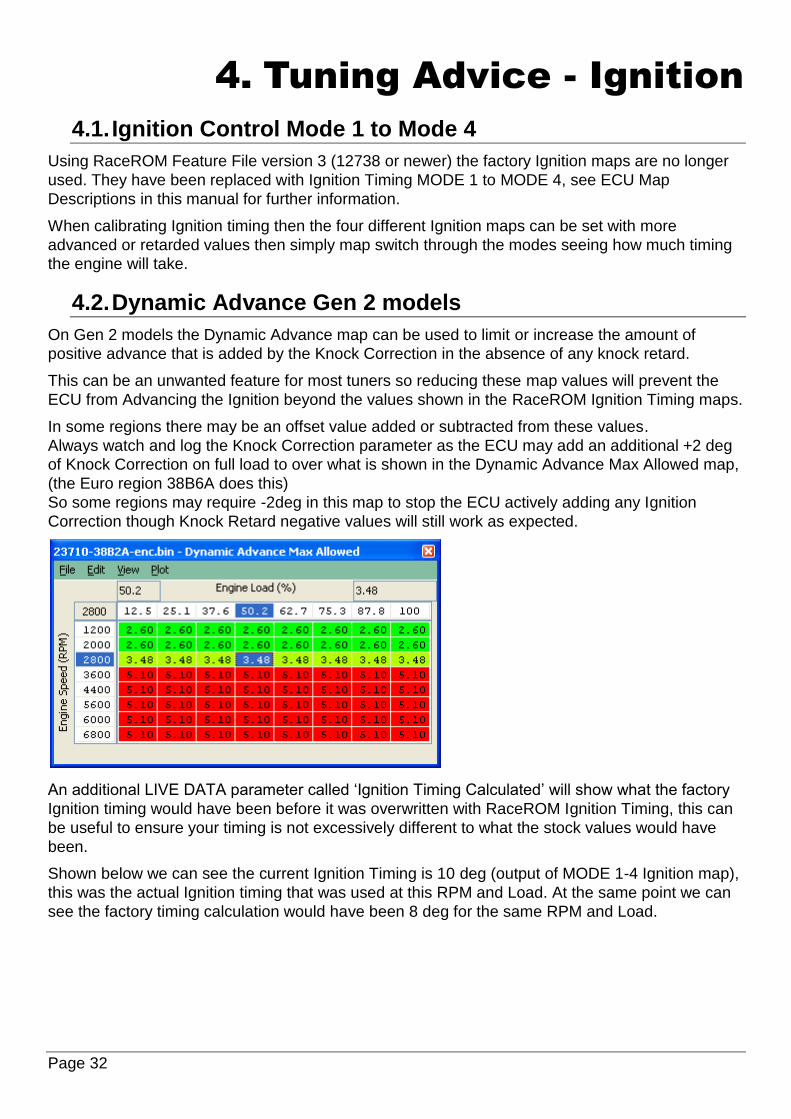
4.2. Dynamic Advance Gen 2 models
On Gen 2 models the Dynamic Advance map can be used to limit or increase the amount of
positive advance that is added by the Knock Correction in the absence of any knock retard.
This can be an unwanted feature for most tuners so reducing these map values will prevent the
ECU from Advancing the Ignition beyond the values shown in the RaceROM Ignition Timing maps.
In some regions there may be an offset value added or subtracted from these values.
Always watch and log the Knock Correction parameter as the ECU may add an additional +2 deg
of Knock Correction on full load to over what is shown in the Dynamic Advance Max Allowed map,
(the Euro region 38B6A does this)
So some regions may require -2deg in this map to stop the ECU actively adding any Ignition
Correction though Knock Retard negative values will still work as expected.
An additional LIVE DATA parameter called ‘Ignition Timing Calculated’ will show what the factory
Ignition timing would have been before it was overwritten with RaceROM Ignition Timing, this can
be useful to ensure your timing is not excessively different to what the stock values would have
been.
Shown below we can see the current Ignition Timing is 10 deg (output of MODE 1-4 Ignition map),
this was the actual Ignition timing that was used at this RPM and Load. At the same point we can
see the factory timing calculation would have been 8 deg for the same RPM and Load.

Page 33
4.3. Coolant Temp display during Map Switch
The four ignition maps can be calibrated for different fuel, in addition we can change the values
shown on the Coolant Temp Gauge during Map Switch Mode to indicate the fuel currently in the
fuel tank.
Map Switch Mode Coolant Temp Gauge display Suggesting Fuel Type
Ignition Timing MODE 1 95 Regular Pump Fuel
Ignition Timing MODE 2 98 High Octane Pump Fuel
Ignition Timing MODE 3 106 Race Fuel
Ignition Timing MODE 4 85 Ethanol based fuel
Default values shown on the Coolant Temp display when Map Switching
Example values that could be shown on the Coolant Temp display when Map Switching

Page 34
So when MODE 1 is selected the Coolant Temp gauge will show 95 (203F)
So when MODE 3 is selected the Coolant Temp gauge will show 106 (228F)
NOTE: The units are in Deg C (Celsius) but on US models the values will be displayed in Fahrenheit . So you will need to reduce the Deg C values so the correct Fahrenheit value is shown on the display. Google offers a simple online conversion. In addition by using the Rev Counter tacho indication for Map Switch Mode then we still have a visual indication of Modes 1 to 4 (requires TCM programming with the latest RRFF version for Tacho Indication).
4.3.1. Intake Air Temp compensation
The Intake Air Temp (IAT) compensation map is used to add or retard ignition timing for a given
IAT. This is very useful for Charge Air readings (if a Nissan Juke type boost sensor with integrated
air temp sensor is used). In this situation then IAT reading is actually Charge Air (post intercooler).
We have fitted and tested a very nice ‘plug and play’ charge air conversion kit where the Intake air
sensor is substituted by the new replacement boost sensor that incorporates Charge Air temp.
This is a great solution for Speed Density conversions, contact Got Boost Performance for more
info.

Page 35
5. Tuning Advice - Fuel
The Nissan GTR fuel control is fully closed loop from Idle all the way to the rev limiter including
light load and full load.
The logging parameter called AFR TARGET will show the current AFR the ECU is trying to
achieve. EcuTek have converted the factory Nissan AF sensor voltage into a more useful logging
parameter called AFR Sensor Bank 1 and AFR Sensor Bank 2.
Typically on a stage 1 car the AFR Sensor Bank 1 or 2 might show 12:1 AFR but independent Wideband sensors (like Motec PLM) will show a more truthful and accurate 11.5:1 AFR. We suggest you always verify your AFR with an aftermarket wideband sensor until you have enough experience to trust the standard sensor readings. The AFR shown will tend to be slightly leaner than the car runs but this can change with full decat exhaust and larger turbo’s (and higher EGT). See the descriptions for the other important AFR maps found under section 1 in this manual. AFR Target – Max at WOT – This can hi-jack the AFR from the Fuel Map at higher RPM on MY14- models. AFR Conversion Table Bank 1 and Bank 2 – This will convert the current AFR Target to a new AFR Target
5.1. Fuel Trims
Increasing fuel pressure from say 3.0Bar to 4.0Bar will not change the AFR as the Short Term and Long Term Fuel Trim will compensate to achieve the Target AFR shown in the fuel map, so watch the Fuel Trims carefully. Fitting a larger Intake MAF tube (stock 66mm to 76mm is a popular swap) will cause the Fuel Trims to compensate for the under reading MAF so ensure you watch the Fuel trims and rescale the MAF accordingly. The short term fuel trim can add or subtract up to 25% (75% to 125%), the long term fuel trim can
add or subtract up to 10% (90% to 110%). You should aim to keep the FT within 10% (90% to
110%) for a good calibration (ignoring transient movements), good calibration would be within 5%
and the gearbox control will also show its appreciation.
Here are two examples of Fuel Trims in action, the left log file shows really good fuel trims but the
right log file is adding +17% to the Injection Volume to achieve the target AFR. If this FT was
117% across the whole RPM range then the 1d MAF scale byte should be increased but as this is
only at higher RPM then I could be a secondary fuel pump issue failing to deliver at higher RPM.

Page 36
Long Term Fuel Trims can be cleared by using the ECU RESET under the Nissan GTR ECM Tool.
They are also cleared after ECM programming.
Be sure to check both Bank 1 and Bank 2, as they have different MAF scaling due to different
airbox designs. Also watch Fuel Trim Long Term and Fuel Trim Short Temp for Bank 1 and 2.
There are different ways to correct the fuel trims, for larger Injectors see below and for larger
Intakes then see the MAF Scaling section.
5.2. Fuel Injectors
The standard Injectors will be close to 100% open when running 1.1 bar boost at high rpm
(6000rpm plus and 560bhp+) so watch carefully, a vehicle fitted with a full sport exhaust system
running 1.2bar+ will max the injectors.
EcuTek can supply the high quality Bosch Motorsport Injectors that are 1050cc (good for 1000+
bhp), see them in the webstore.
The maximum Injector size you can enter in the factory map is 800cc, this is a limitation of the
Nissan ROM code and not EcuTek.
For replacement Injectors over 800cc use the map called Injector Flow Scaling (RaceROM) you
can choose a different Injector size for each of the map switch modes (useful for Ethanol tuning in
different modes).
If the Injectors are to be replaced then choose at least 800cc plus. When fitting larger Injectors it’s
important to reduce the Minimum Open Time from 1.8ms down to 1.2ms, otherwise 1.8ms on
1000cc Injectors will mean 12:1 AFR at Idle. Using the EcuTek 1015cc Injectors we typically run a
1.0ms Offset combined with a 975cc Injector size and we achieve very tight fuel trims.
Some popular cheap injectors on the market cause black smoke, EcuTek injectors do not have the
issue so choose wisely and remember you get what you pay for!
5.3. Fuel Pump (Secondary Control)
The Secondary Fuel Pump is only switched on when a certain Injector Duty is achieved (see the
Fuel Pump Control section earlier in this manual for more information).
The 2nd Fuel Pump has been calibrated for stock 570cc injectors and the 2nd pump will activate
around 2500rpm on full load (34% Injector Duty) BUT when fitting larger Injectors (1000cc for
example) then the same Injector Duty will be around 3800rpm meaning the 2nd fuel pump switches
on too late and the fuel rail pressure will start to as the Primary pump runs out of flow capacity!

Page 37
So it is very important when fitting larger injectors that the Secondary Inj Duty% Threshold is
reduced relative to the Fuel Injector size % increase otherwise the 2nd Pump will switch on too late
and the fuel rail pressure will drop (as shown in the following log file screenshot).
In this example below a Fuel Pressure sensor has been imported through the Boost Sensor #1
and the Fuel Pressure is shown in the Log File as Custom Map N Output.
The GTR static fuel pressure at sea level is 4 bar (60psi), with 1 bar boost the fuel pressure should
be 5 bar (75psi). During this power run you can see Boost Bank 2 climbing to 1 bar boost with the
Fuel pressure climbing from 4 to 5 bar by 3000rpm but by 3500rpm the Primary pump has run out
of capacity and rail pressure is starting to drop as low as 4.6bar during this dyno pull.
The 2nd pump finally kick in 3900rpm (34% Injector Duty) and the fuel pressure increases from 4.6
to 5.2bar and is regulated back down to 5bar.
Fuel Rail Pressure dropping as the 2nd Fuel Pump switches on too late!!
See Custom Maps manual for more information on importing pressure sensors and how to log and
display on the setup Fuel Pressure sensor Fail Safes.
5.4. MAF Rescale for Larger Intakes
When fitting larger Intakes the MAF sensor scaling will need to be recalibrated to ensure tight AF
correction at light load and full load. These Fuel corrections are called Fuel Trim Short Term
(FTST) and Fuel Trim Long Term (FTLT). Accurate FTST/FTLT are needed for accurate AFR
tuning but also for correct Torque Output (Nm) for smooth TCM control and avoiding clutch slip.
The standard GTR Intake MAF Tube diameter is 66mm, most aftermarket intakes are 68mm,
72mm the most common is 76mm.

Page 38
With larger Intakes (like 76mm) you MUST increase the ‘MAF Sensor Scaling (% to g/s) for Load’,
this is a coarse adjustment for MAF scaling and this will make 90% of the MAF rescaling that is
required, it’s a MAF surface area constant.
The factory default value is 153 for the factory 66mm MAF tube, this should be increased to 203
for 76mm MAF tubes. This is based on the surface area increment amount.
The surface area calculation is as follows: Radius squared * PI = Surface area
So for 66mm MAF tubes: 33mm Radius, 33x33=1089mm2, 1089 * 3.14 (Pi) = 3419mm2
So for 69.5mm MAF tubes: 34.9mm Radius, 34.9x34.9=1219mm2, 1219 * 3.14 (Pi) = 3830mm2
So for 76mm MAF tubes: 38mm Radius, 38x38=1444mm2, 1444 * 3.14 (Pi) = 4534mm2
Now if we divide the new 76mm MAF housing surface area by the stock 66mm MAF housing
surface area we get the percentage increment amount.
So 4534/3419 = 1.326 or if you prefer ‘the 76mm MAF tubes have a 32% greater surface area’.
So if we simply multiply the 1d map called ‘MAF Sensor Scaling (% to g/s) for Load’ by 32%
153 * 1.326 = 203. If the MAF tubes are 69.5mm (2.75 inch) then enter 171
So with the MAF Tube now calibrated to the larger Intake size you can now make the Fine MAF
tuning with the 2d MAF Scale for the corresponding bank (Bank #1 or Bank #2).
Start the car and make a log at Idle, Fast Idle, Light Load and Full Load watching carefully the
AFR and Knock Correction. Be sure to including the following parameters in your log file:
Fuel Trim Short Term B1/B2
Fuel Trim Long Term B1/B2
AFR B1/B2
MAF Volts B1/B2
Mass Airflow (g/s) B1/B2
If the FTST is at 120% then the ECU is
increasing the Injector Open Time ms by
+20% to achieve your Target AFR from the
Fuel map, if the FTST is 85% then the ECU is
reducing Inj ms by -15% to make the target
AFR. So for a reasonable FT error (over
110% or under 90%) the 2d Maf Scale (g/s)
should be adjusted at this point by 50% of the
FT correction value.
So as an example let’s say we see Fuel Trim is about 120% between 1.04v and 1.7v MAF Volts.
We simply increase MAF Sensor Scale #1 by +10% on the 2d MAF Scale for Bank #1 therefore
reducing the STFT at this point. The same sequence should also be followed for Bank #2 and all
adjustments should be smoothed into the local values.

Page 39
5.5. MAF Rescale for Larger Intakes using SD
It’s also possible to rescale MAFs using Speed Density. This is very simple and provides
verification that our MAF scaling is correct.
The screenshot below shows two log files created from a car running on SD.
76mm Intakes fitted running on SD Stock 66mm Intakes fitted running on SD
You can see the right hand log shows a stock 66mm MAF tube and the Mass Airflow reading from
SD (Yellow line) and MAF Mass Airflow (Red line) are very close.
After fitting the new 76mm Intakes you can see the left hand log file shows the MAF Mass Airflow
B1 (Red line) reading has dropped but the SD Mass Airflow (Yellow line) is still accurate and the
car runs fine as its running on SD.
Now we can leave the car on SD and simply increase the MAF scaling until the MAF Mass Airflow
(Red line) reaches the SD Mass Airflow (Yellow line). See the previous pages on MAF rescaling
for further info on the rescaling technique.
Once the MAF Mass Airflow is the same as the SD Mass Airflow then we can turn off SD as we
have a perfectly scaled MAF curve!

Page 40
6. Tuning Advice - Boost Control
RaceROM Boost Control Phase 5 Update
EcuTek have now completely rewritten the GTR Boost Control with a more simplistic and easy to
calibrate control system, we strongly recommend that you use the Phase 5 RRFF version 19472
or newer for any GTR ECM tuning.
To use the Phase 5 RaceROM Boost Control ensure that the Enable EcuTek Boost Control box is
checked in the Enable Special Features window once checked the OEM Boost Control Maps will
no longer work.
See the Phase 5 GTR supplement pdf manual for further details on the new RaceROM boost
control maps.
Factory Boost Control – Not Recommended
The factory boost control on the GTR is very clever even though it can appear complex at first
glance.
EcuTek have spent many many hours on hard disassembly to understand the factory boost control
strategy. Spend some time to look through the various boost control maps to understand the
various limiters and airflow control logic. Below is a description of each of the important boost
control maps.

Page 41
6.1. Desired Turbine Wheel Air Flow
This map must be calibrated to the characteristics of the turbo. Once set, desired boost can be
adjusted via the Desired Boost map. This map will need to be modified if larger turbos are fitted.
It will also need to be modified if the flow of the exhaust, intakes or intercooler are improved.
6.2. Surplus Airflow to Wastegate Flow
The surplus Mass Airflow is multiplied by a value from this map in order to calculate the flow rate
of exhaust gas that must be vented through the wastegate. This map may need to be modified if
larger turbos are fitted, as the relationship between exhaust gas flow and pre turbo exhaust gas
pressure will vary.
6.3. Wastegate Flow to Opening Angle
Once the required wastegate airflow is known, this map calculates the wastegate opening angle
required to vent the desired flow. This map is calibrated to reflect the characteristics of the
wastegate orifice. You only need to modify this map if you port the wastegate orifice.
6.4. Wastegate Angle to Duty Cycle
Converts desired wastegate opening angle to the wastegate duty required. Values vary with the
current boost pressure, since the pressure feed to the actuator diaphragm is fed from the boost
pressure. So for a higher boost pressure, a higher wastegate duty (bleed off) is required to
maintain the correct opening angle. You only need to modify this map if you replace the wastegate
actuator or alter the spring tension.
If correctly understood and calibrated the boost control will be extremely competent.
In our experience using the RaceROM Boost Controller we can accurately recalibrate the boost
control for different pressures with precision calculations and detailed log files to cross reference.
In the majority of cases the only map that should be altered is the Desired Turbine Wheel Air
Flow map. Following the steps below will enable you to make accurate boost control calibration.
Make a log at 0.8 bar, 1 bar and 1.2 bar (assuming you are able to run these different pressures without risk of damage to the engine) be sure to include all the important parameters used in boost control as listed in Live Data section (like Calculated Airflow, Wastegate Angle and Turbo Dynamics)
Compare Target Boost and Boost Error and Calculated Airflow. By opening the Desired Turbine Wheel Air Flow map you can now see the corresponding Target Boost and Calc Airflow lookup parameter and this can be verified as the diagnostic parameter called Desired Turbine Wheel Output.
If the boost is under target then the Desired Turbine Wheel Air Flow values needed to maintain the turbine speed are too low (and hence the boost is low), so simply raise the values to increase the amount of airflow that will hit the turbine wheel and increase turbo speed!
The same procedure can be applied for an over boost situation.
For greater accuracy set both Turbo Dynamics Integral and Proportional to Zero during boost calibration.
A final boost tuning tip is if your Target Boost is 0.8 bar and you generate a steady 1 bar then
simply copy and paste the Desired Turbine Wheel Air Flow column for 0.8bar into the 1 bar
column! This can be repeated for other boost targets as well.

Page 42
We also advise that you start your tuning based on any EcuTek example ROMs where available.
The example ROMs have the Desired Turbine Wheel Air Flow maps calibrated and in addition the
X axis rescaled for greater resolution at higher RPM.

Page 43
7. Tuning Advice - Torque Control
The GTR Engine Control Module (ECM) and Transmission Control Module (TCM) depend
completely on Torque calculations.
It is critical that the Torque value output from the ECM is accurately calibrated, if it is not then
pulling away, gear shifting and gear selection will range from being unresponsive, hesitant and
uncontrolled to dangerously aggressive and unbearably hard and this could drastically shorten the
life of the transmission.
Calibrating the Torque values is not normally needed when using EcuTek RaceROM version 3 or
newer, these later RRFF have superior high load rescaling and high resolution Torque map
definitions which provide very smooth and detailed interpolation, they are calibrated to 1000Nm.
When used in conjunction with the latest LC5 TCM ROM (KJ or 38B series TCM ROMs) then the
driveability will be better than any stock GTR and will be silky smooth.
How to calibrate the Torque Actual map
Calibrate your Fuel Trims until they are between 90 to 110%, if you can fine tune them to be as
tight as 95 to 105% then even better, this needs to be done at Idle, under cruise conditions and
then full load all the way to the rev limiter.
Assuming the Fuel Injector scaling is correct then you need to adjust the MAF scaling (or the SD
VE map if you are running on SD) until the fuel trims are as close as you can get to 100%.
By adjusting the MAF scaling or SD VE map you also correct your Engine Load (X axis of the
Torque Actual map) and therefore the output of the Torque Actual map.
Understanding the Torque map
To understand the effect of the Torque Actual map we need to exaggerate the changes for the
purpose of example, see below.
If you drastically reduce the Torque map values then the Torque value reported to the TCM will be lower and the clutches will slip when pulling away, on gear changes and also full time slip on full load, the clutch life will be counted in seconds if this happens.
If you drastically increase the Torque map values then the Torque value reported to the TCM will be higher and the clutches will be engaged at Idle and the vehicle will creep in traffic and also the gearchange will be very firm.

Page 44
Using RRFF version 3 or newer there is no reason to adjust this map. If you have replaced the clutch packs with uprated clutch packs then you may need to reduce these values at lower Engine Loads for improved drivability (below 100% Engine Load). But try adjusting the Clutch Touch Points and Clutch Capacity before adjusting the Torque Actual map, NOTE: Increasing the Torque values in the Torque Actual map will NOT make more power, it will only upset the drivability of the vehicle! The torque value is sent over the CAN bus to the TCM, this is used to calculate clutch clamping pressures, as above if the torque value is too low then the clutches will slip. Make a log file of the TCM (using the TCM ROM) then you will see the following: Clutch A will be used for gears 2, 4 and 6 Clutch B will be used for gears 1, 3 and 5 You can see that this log file below shows that in 4th Gear the clutch slip is between 0 and 15rpm, this is pretty normal. You can see that Clutch A Pressure is flat lined at 17.1bar, this is slightly higher than normal as most clutch pressures will be around 16.5bar. If you feel the clutches are slipping on full load then either add 20% to the Torque Actual map over 80% Engine Load or even easier and preferred is to increase the Clutch Capacity to +8 and make another power run and log of the TCM, see if the clutch slip reduces, if so then increase the values in the Torque Actual map.

Page 45
8. Nissan Factory Launch Control
8.1. What is the Nissan GTR Launch Control?
The Nissan GTR has a built in factory Launch Control Mode, when conditions are correct this will
deliver an extremely effective launch condition. When entering the special mode the throttle
butterfly will react quickly providing a burst of Engine Torque which will load the transmission and
drivetrain for a blistering launch condition.
This launch condition is often mistaken and confused for the typical ‘stall test’ launch that can be
induced by on most Auto gearboxes models at the traffic lights (left foot on the Brake, Accel pedal
to the floor and wait for the lights to change). This low torque/low RPM slipping convertor/clutch
launch is not the same or nearly as aggressive as the special Launch Control Mode, though this
type of launch is still very effective on the GTR when used.
8.2. How do I make the Nissan GTR launch Control work?
When the Engine and Gearbox oils are up to temperature, the vehicle is stationary and the correct
settings are applied to the 4WD and VDC switches along with Manual Gear Selection (not in Auto)
then the factory Launch Control can be used (assuming the factory TCM ROM has it enabled by
Nissan, see NOTE below!).
With your left foot on the brake and quickly pressing the Accel pedal to the floor, the engine RPM
will rise very quickly to around 3300rpm or 4500rpm (depending on the exact LC version installed),
this RPM will be held for around 5 seconds until the ECU will force release of the LC mode to
prevent strain and heat on the clutches and gearbox.
If the 4WD switch is simply moved out of RACE mode and the test repeated then LC mode will not
enable and the difference is clearly felt.
NOTE: LC2 and some LC3 have the factory LC mode disabled in the TCM ROM, this can be
enabled using EcuTek software.
8.3. Launch Control versions defined
LC1 (early “JF” series TCM ROMs)
Early 2008-2009 GTR models have a built in Factory Launch Control system called LC1 which is
an aggressive Launch Control Mode that put considerable strain on the drivetrain.
LC1 Launch RPM is factory set at 4500rpm and is found in the Engine ECU ROM in the 1D
Launch Control RPM map:
LC1 Launch Control mode will only activate when:
Oil temp is over 65 Deg C
4WD is set in Race Mode (Red Light ON)
VDC is OFF so traction control does not operate (Yellow Light ON)
Gear Level selection is in MANUAL and 1st Gear is selected

Page 46
LC2 (“JF” series TCM ROMs)
On later JF cars Nissan simply disabled the launch control in the TCM ROM, this was sometimes
applied during servicing at Nissan dealerships and it’s claimed that the launch control functionality
was removed to maintain manufactures warranty.
You can see below the LC2 TCM ROM called JF09DBA has the factory Launch Control disabled
by Nissan, to re-enable simply check the box, save the ROM and program into the TCM ECU. This
will enable the LC1 Launch Control code again in the LC2 ROM
LC1 and LC2 can only be used with VDC OFF and in Manual – R mode and conditions must be
met as described above.
LC3 (“JW” series TCM ROMs)
2010-2011 Gen 1 GTR models have a revised Factory Launch Control system which is enabled
on all JW models. LC3 is less aggressive Launch Control Mode that is easier on the transmission
and drivetrain. LC3 works with VDC ON (Traction Control working).
LC3 Launch RPM is factory set at 3300rpm and is found in the Engine ECU ROM in the 1D
Launch Control RPM map.
LC3 Launch Control mode will only activate when:
Oil temp is over 65 Deg C
VDC is ON so traction control is working (RED Light ON)
Gear Level selection is in MANUAL and 1st Gear is selected
As seen below LC3 can be enabled in Manual with or without 4WD in R mode (Race)
If you wish to allow LC to work in other conditions (like Auto or without VDC etc) then simply
enable the condition in the TCM ROM (though the associated risks must be accepted).
NOTE: LC should be enabled in BOTH Mode A and Mode B if used with any Gen 1 GTR models.

Page 47
LC4 (“KB”, “KJ” and “38” series TCM ROMs)
2011-2014 Gen 2 GTR models have the latest and most refined gearbox control code, along with
the most advanced Launch Control strategy with improved clutch control, faster gear selection and
much smoother gear changes compared to earlier TCM code versions.
LC4 Launch RPM is factory set at 4100rpm and is found in the 1D Launch Control RPM map:
LC4 Launch Control mode will only activate when:
Oil temp is over 65 Deg C
VDC is ON so traction control is working (RED Light ON)
Gear Level selection is in MANUAL and 1st Gear is selected
LC4 can be enabled in Manual with or
without 4WD in R mode (Race).
If you wish to allow LC to work in other
conditions (like Auto or without VDC
etc) then simply enable the condition in
the TCM ROM (though the associated
risks must be accepted).
NOTE: LC should be enabled in BOTH Mode A and Mode B if used with any Gen 1 GTR models.
The different configuration settings that are required for Launch Control to be enabled are
summarised below:
JF series TCM (LC1)
VDC on VDC off
Auto NO NO
Auto-R NO NO
Manu NO NO
Manu-R NO YES
JW series TCM (LC3)
VDC on VDC off
Auto NO NO
Auto-R NO NO
Manu YES NO
Manu-R YES NO
KB, KJ, 38 series TCM (LC4)
VDC on VDC off
Auto NO NO
Auto-R YES NO
Manu NO NO
Manu-R YES NO

Page 48
EcuTek ProECU Nissan GTR TCM software allows the tuner to modify the LC setting conditions
so that launch control can be activated without R-mode, or with VDC off or however you want.
NOTE: It’s recommended that the latest TCM ROM is used on all Gen1 or Gen2 vehicles.
8.4. TCM and ECM ROM compatibility
It’s recommended that the latest Engine ECU ROM is also used in conjunction with the LC4-LC5
TCM code. The JW ECM code is better suited and more compatible for the later Gen 2 TCM code
versions (LC4-5).
For Gen 1 models the latest ECM code version would be the JW series ECU ROM.
Some Examples are shown below for Gen 1 GTR:
Factory ECM ROM Suggested ROM Factory TCM ROM Suggested ROM
JF51A Euro JW93A Euro JF04BBA KB51BDA
JF04A Japan JW90A Japan JF02BBA KB51BDA
JF30A USA JW92A USA JF09DBA KB51BDA
To see the latest version ECM ROM that should be chosen for your region, go to Feature &
Licence Information under the Help menu, and the select the Supported Tuning ECUs tab:

Page 49
The Auto Gearbox Learning sequence should always be carried out after any TCM programming.
The Clutch Capacity and Clutch Touch Points should also be calibrated after any TCM
programming.
We recommend that the LC5 TCM called ‘32085-KJ10BDA-RRFF 14433 Rev Counter Map Switch Enabled LC5 enc.bin ‘ is used in all TCMs (even if the ECM has not or will not been programmed with ProECU). This can be found in the TCM Example Rom folder. 2008 JDM TCM issues Some very early Gen 1 JDM region models may seem incompatible with later LC2 to LC5 TCM
ROMs.
The CEL light is shown after programming but no DTCs are stored.
Programming the original LC1 TCM ROM version again will solve the DTC issue but it doesn’t help
us improve the TCM software.
It is possible to use the far superior LC5 ROM in these ECU by ensuring the ECM and TCM DTCs
are cleared correctly and the ECM is Reset after programming the later TCM software.
The READ and CLEAR DTCs sequence will need to be repeated 2 or 3 times before the TCM
DTCs are successfully cleared, so persevere and eventually the TCM CEL will clear.
You can carry out the TCM Auto Learn sequence followed by manual Clutch adjustments.

Page 50
9. How to Setup
9.1. How to set up Speed Density
EcuTek RaceROM Feature Files (RRFF) offer a Speed Density tuning option, this is a MAP
sensor based load input into the ECU (compared to the more forgiving factory MAF sensor based
load input).
In certain situations Speed Density is more suitable over a MAF based input, this are usually:
The air speed through Large MAF tubes is too slow to accurately measure for a stable Idle
Turbo compressor wheel cause reverberations up the intake pipe and upset the MAF sensor
reading
Turbo installs use Vent To Atmospheric Blow Off Valves (BOV’s) instead of preferred recirc
designs
The stock MAF’s are flat lined at 5volts and cannot read any higher than the 5v limit (where ideally
a slightly larger MAF tube should be fitted like 66mm to 76mm)
In these situations the Speed Density or Hybrid Speed Density can be used.
The SD VE map is against Engine Speed (RPM) and Manifold Relative Pressure (Bar). The values
in the map are volumetric efficiency (VE) %.
The older RRFF SD Map had Mass Airflow values in the SD map but the latest RRFF now uses a
superior VE based SD calculation which we will cover here.
When the SD map is active it simply replaces the current Mass Airflow (g/sec) reading that would
normally come from the MAF sensor, therefore ALL load calculations are not affected by the MAF
sensor at all.
When the SD map is correctly calibrated there is little difference from running on MAF and the SD
VE map works like this:
INCREASING the SD values will make Engine Load higher therefore retarding the Ignition and
increasing the Injection volume amount therefore making the AFR richer.
REDUCING the SD values will make Engine Load lower therefore advancing the Ignition and
reducing the Injection volume amount therefore making the AFR leaner

Page 51
The SD map uses the Plenum based MAP sensor to calculate SD. It does NOT use the pre
throttle Boost Pressure sensors. The stock MAP sensors can read to 2.7bar absolute, any
pressure over 2.72bar absolute will need a 4bar MAP sensor fitting.
The default SD map has been calibrated for a stock vehicle, the VE based calculation will be
seriously affected by any fundamental change in VE (like fitting larger turbochargers or changing
the camshafts).
Charge Air Temp (CAT) also plays a critical part in the VE calculation and as a charge air temp
sensor is NOT fitted by the factory we have to assume a fixed temperature and then make a
calibrated compensation based against Intake Air Temp.
9.1.1. No air temp sensor fitted in the charge pipe
The Speed Density Temp Compensation map will adjust the SD VE calculation based on the
current IAT, therefore attempting to
calculate the true air density by
calibration.
9.1.2. Intake Air temp sensor fitted in the charge pipe
If the Air Intake Temp sensor (AIT) has been placed in the charge pipe and the IAT is measuring
true CAT (after the turbo and intercooler)
then we do NOT need to use the ‘Speed
Density Temp Compensation’ map (as VE
calculation is including true CAT), in this
situation we need to select the CAT
Acquisition Method of ‘IAT sensor measures
the CAT directly’ option.
We also need to set the values in the
‘Speed Density Temp Compensation’ to 1
as we are not ‘guessing’ the CAT anymore.

Page 52
9.2. How to set up Hybrid Speed Density
Hybrid SD mode options
RaceROM’s powerful Hybrid Speed Density allows the Load Input to be switched between MAF
and SD as required. The transition can be ‘MAF then SD’ or ‘SD then MAF’.
Hybrid SD is a great solution if your MAF volts
are hitting 5volts at a higher RPM.
In this situation you can run the superior MAF
load input for most of the time then switch to SD
when the MAF is nearing 5 volts.
In this example to the left we would switch to
SD around 5500rpm where the MAF is at
4.90volts and just before the MAF’s hit 5volts.
Remember to check the MAF volts on both
Bank #1 and Bank #2 as one MAF might flow
more than the other.
The hybrid SD condition to switch between
MAF and SD or SD then MAF can be one or several of the following:
Engine Speed (RPM)
MAP (Bar)
Mass Airflow (g/sec)
In the previous example we would specify that past 5500rpm we switch to SD but we can also say
that boost pressure has to be over 1.2bar as well, this would prevent the SD from ever working
below 1.2bar and below 5500rpm.
So the engine will be running on MAF at Idle, low load and it will stay on MAF until 5500rpm AND
the boost exceeds 1.2bar relative.
As soon as the RPM drops BELOW 5400rpm or the Boost drops BELOW 1.15bar then the ECU
will switch back to MAF.

Page 53
We need a smooth transition when swapping between ‘MAF and SD’ or ‘between SD and MAF’.
For this to happen the MAF and SD have to read very similar airflows at the switch point.
One major point to make is that ProECU can LOG the output of the MAF sensors even if they are
not used by the ECU (i.e. the ECU is running on SD not MAF).
So to calibrate for a hybrid transition we need to Enable SD earlier than the switch point, if the
switch point is 5500rpm then enable SD over 4000rpm. Even though the ECU is using SD past
4000rpm the MAF can still be logged, now we need to log the following three parameters.
Mass Airflow Absolute (MAF) (g/s) – The mass airflow reading from the MAF sensor
Mass Airflow Absolute (SD) (g/s) – The mass airflow calculation from the SD map
SD Volumetric Efficiency (%) – The output of the SD map
As seen below the ECU is currently running on SD, we know this because the SD VE shows 95%
and Mass Airflow readings for MAF and SD are different.
If the ECU was using MAF the SD VE reading would be 0% and the Mass Airflow readings would
be the same.
The Mass Airflow readings for MAF and SD are very close between 3500 and 4500rpm so it would
be a very smooth transition to swap from MAF to SD (or SD to MAF) at any RPM shown below.
The log file shot below shows the ECU running on SD.
The Mass Airflow is from our SD map, the MAF sensor reading is also logged but is not used by
the ECU.

Page 54
Here is a Good Hybrid SD transition
At 4000rpm the ECU swaps
to SD and the SD VE value
moves from 0 to 95.8%, the
Mass Airflow reading comes
from SD map and not the
MAF sensor (but they read
very similar values).
This is a great example and
the switch point from MAF to
MAP will be a smooth
transition.
Here is a BAD Hybrid SD transition
This is BAD hybrid tuning and the car
even had clutch slip problems during
transition. In this example the SD is
switched ON at 3000rpm.
You can see the SD VE parameter go
from 0% to 72.8% when SD activates
and SD now provides the ECU with
the Mass Airflow input value for its
load calculations.
You can also see that the Mass
Airflow calculated from the SD VE
maps (in YELLOW) suddenly drops
from 106 grams to 80 grams but the
Mass Airflow shown by the MAF
sensors (in RED) continue to read a
more sensible and true Mass Airflow.
In this case the SD map has been
poorly calibrated!
As the SD is enabled the Mass Airflow
drops and engine load drops
drastically and Ignition timing jumps
from 17 to 26 degrees. The Fuel Trim
also went to 125% to add enough fuel.

Page 55
The SD map needed increasing from 76% to 98% to fix this issue then all was good.
So to make smooth transitions it’s critical to make sure MAF and SD read close before and after
the transition swap.
You need to ensure that the FTs are correct running on MAF, if not then adjust the MAF scaling
until they are correct.
Then enable SD and ensure the FTs are correct and if not then adjust the SD map. Then you can
set the conditions to switch as you wish!
As you can enable SD in any of the 4 map switch modes you could use MAF in MODE 1 and SD
in MODE 2 to get a back to back result.
9.3. How to rescale the MAP Sensor scaling
By using the RaceROM Hi Boost map feature we can increase the boost to 3 bar+.
There are 3 MAP sensors fitted to the GTR and they are all 2.83 bar absolute sensors.
One MAP sensor is located in the plenum (Inlet manifold) and can show manifold vacuum, this
MAP sensor is used for RaceROM Speed Density and the also the Boost Pressure display on the
driver information display.
The other two MAP sensors are fitted pre throttle (one in each bank) and they are used for boost
control and boost limit.
Any vehicle running more than 1.7bar boost will need 3 x new MAP sensors fitting pre and post
throttle to be able to control boost pressures over 2.70bar absolute using the factory boost control
system.
But if Custom Maps is used for boost control (where the plenum based MAP sensor can be used
for the pressure reading) then the two pre throttle MAP sensors do not need to be replaced and
the boost control can be based on the plenum based MAP sensor.
But please note that the boost limit is based on the pre throttle MAP sensors and if they are still
stock items (2.83bar) then the boost limit will never trip with values greater than 2.7bar in the map.
In this case you can create a custom map for fuel cut against the Inlet Manifold based MAP
sensor.
Standard Map Sensor Scaling is as following:
Multiplier (bar/volt) 0.613
Offset (bar) -0.235
So : 0.613bar x 5 volt = 3.065bar
3.065bar – 0.235bar Offset = 2.83bar (for the standard MAP Sensors)
We have tried and tested the AMS supplied 4bar MAP sensors.
AMS recommend the following settings:
Multiplier (bar/volt) 0.83
Offset (bar) 0.00
So :
0.83bar x 5 volt = 4.15bar
With zero Offset value the AMS sensors are rated at 4.15bar Absolute.

Page 56
Below you can see the AMS recommended setting for their 4bar map sensor vs stock MAP sensor settings. As you can see its possible to calibrate the input voltage values as well as the output pressure values.
Also below you can see the Switzer recommended setting for their 5bar map sensor that were supplied by Switzer.

Page 57
9.4. How to set up Custom Maps Boost Control
By using custom maps it possible to rewrite the factory boost control system, this can be useful when tuning for larger turbo’s, stronger actuators and external wastegates. You can set the wastegate duty as a fixed WG duty % for a target boost pressure, this is a very crude and basic open loop boost control system but it can be useful when setting up a heavily modified vehicle where there are a lot of variables at the start of the tuning. Once the Ignition and Fuel calibration is dialled in then you can enable the proportional and integral compensations for the current ‘boost error’. This will create a fully closed loop boost control system. If you wish to use the boost control in open loop then simply do not enable the proportional or integral maps or simply enable them in other modes (like Mode3 or Mode4) so you can see the affect they have on the WG duty. The example below shows 3 custom maps configured for a custom boost control setup.
Map A is WG Duty for a Target Boost pressure Map E is WG Duty Proportional addition for boost error Map F is WG Duty Integral addition for boost error The current Target Boost pressure is output of the 3d ‘Target Boost’ map, the RaceROM Boost Controller (RRBC) is then considered. The current target boost is always the lowest boost target value, so if the output of the 3d ‘Target Boost’ map is 1.2bar but the RRBC setting is 0.9bar then the Target Boost Pressure is 0.9bar and this will be the X axis input value for Map A. But if the current RRBC setting is 1.4bar then the Target Boost Pressure would be 1.2bar. You can see and log the current Target Boost value shown under Live Data.

Page 58
9.4.1. Custom Map A – Wastegate Duty for a Target Boost Pressure
X axis is Target Boost Pressure (bar)
Y axis is Engine Speed (rpm)
Map values are Wastegate Duty (%) The map output will be the Wastegate Duty% for the current Target Boost pressure. This will overwrite the factory WG duty control. In this example below at 3400rpm and 1.2bar Boost Target the WG Duty will be 65%.
Calibrating the base Wastegate Duty using Custom Map A
Using RRBC its very easy to calibrate and create a base WG Duty Map A profile using the following tequnique but ensure no proportional or Integral maps are enabled.

Page 59
Fill Map A columns with 0 to 100% values like shown to the left then make a few power runs starting at 0.7bar and increse the RRBC in 0.1bar incremements and log the results. You can now see what boost pressure is created for a given WG Duty. So if 20% WG Duty makes 0.9bar then enter 0.9 in the X axis column above the 20% column. If 40% produces 1.1bar and 60% produces 1.3bar then simply enter the boost value in the X axis above the corresponding WG Duty column.

Page 60
9.4.2. Custom Map E - Wastegate Duty Proportional Control
X axis is the current boost error (Bar)
Y axis is Engine Speed (RPM)
Map values are Wastegate Duty proportional compensation factor.
Custom Map E will add the map output value to the current WG Duty (output of Map A) for a given RPM and Boost Error. In the example shown below the X axis is boost error (the difference between the Target Boost and Manifold Relative Pressure MRP). The Y axis is Engine Speed.
In this example above at 3200rpm and -0.375bar boost error (so under the boost target) Map E will ADD a value of 26 to the current WG Duty therefore increasing the WG Duty. Assuming the current value for Map A to be 65 then the WG duty will increase to 91 (65 + 26) to give a final WG Duty of 91%. As the boost (MRP) increases and nears the boost target then the size of proportional value added will decrease accordingly and as the Boost Target is achieved the proportional amount added will be zero. If the boost overshoots the target boost value then Map E will REMOVE WG Duty as well. NOTE: The Proportional value (output of map A) is a one time only added addition and it does not accumulate like an Integral value will do.

Page 61
Calibrating the Proportional Custom Map
We suggest that the proportional and integral maps are not enabled until Map A for base WG Duty
has been profiled and is fairly close for good tight boost control.
We then suggest you create an overboost condition and then enable the proportional and integral
maps in other modes to see the individual results.
The following sequence is great for producing an accurate proportional or integral map.
Ensure Map A is accurately calibrated so it delivers the correct boost pressure for a given target
boost pressure then simply ADD minus -0.20bar to the X axis as shown below.
So now the column for 1.2bar becomes 1.0bar and WG Duty increases from 52% to 64%.
When you select 1.0bar with RRBC you will get 1.2bar and you can see how the Proportional
control deals with the overshoot, log the INTERIM and RESULT of Custom Map E to see the
proportional component working.
If the boost reduces from 1.2bar to 1.1bar then you have to increase the proportional values for a
0.1bar boost error so the boost can be reduced further.
If the boost reduces from 1.2bar down to 0.9bar then you have to reduce the proportional values in
Map E for a 0.1bar boost error.

Page 62
We suggest you double or halve the values in Map E to increase or reduce the boost accordingly.
The proportional addition should correct the boost instantly and there should be no over or
undershoot if the proportional values are correct.
In fact the output of Map E (Map A WG duty plus Map E Proportional WG Duty component) should
be the actual the WG duty value shown in Map A before you rescaled the X axis.
Further on from this if you have not rescaled Map A X axis then the output of Map E shows the
values you should enter into Map A at a given RPM if the boost error is zero(as Map E has
corrected the WG Duty to produce the Target Boost pressure you have demanded).
This method can soon populate an accurate proportional map suitable for the size of your
turbocharger.
Once your proportional map is calibrated then turn off Map E and enable Map F to calibrate
Integral map in the same way.
9.4.3. Custom Map F - Wastegate Duty Integral Control
X axis is the current Boost Error (Bar)
Y axis is Engine Speed (RPM)
Map values are Wastegate Duty Integral compensation factor. In the example shown below the X axis is boost error (the difference between the Target Boost and Manifold Relative Pressure MRP). The Y axis is Engine Speed. Custom Map F output value will be added the current WG Duty but as an integral, so the value will keep increasing over a period of time (several times a second). The proportional value (output of Map E) will also be added if the proportional map has been enabled.

Page 63
In this example on the previous page at 3600rpm and -0.3bar boost error (so under the boost target) Map F will ADD a value of 0.06 to the current WG Duty (Map A plus Map E) therefore increasing the WG Duty. Assuming the current value for Map A to be 65 and Map E to be 26 then the WG duty will increase from 91% to 91.06% (65 + 26 + 0.06). But as the Output Definition is ‘Add map output to Integral, Add Integral to Channel’ then this 0.06 value will quickly increment on each calculation therefore causing the WG Duty to rise quickly over a time period for a continuous boost error. If the boost pressure overshoots the Target Boost value then Map F Integral component will also REMOVE WG Duty. If the rate of change (Increment or decrement) is too fast then halve the values and retest. If the rate of change is too slow then double the values and retest.
The Integral Min/Max has been set so it can only add or subtract a maximum value of 20, this prevents the Integral from drastically changing the WG duty over a time period like during spool and part throttle conditions. To further improve the boost control logic the Integral control (Map F) has been configured with an Activation Definition. As shown to the left the Integral control (Map F) is only allowed to work when the MRP is over 0.9bar and it will stop working below 0.88bar. So the Integral control can only adjust the WG Duty on full load. This will prevent the Integral from ramping up (or down) the WG Duty at part throttle conditions.
Calibrating the Integral Custom Map
The Integral will not correct the boost instantly like the proportional map does, the Integral takes
times and you will see the boost reduce (or increase) over a time period (0.1 to 2 seconds).
If the Integral takes too long to correct the boost pressure then double the values in Map F so the
WG Duty reduces more quickly.
If the WG Duty redcues too quickly and the boost begins to oscillate then halve the values until the
boost is more stable and then fine tune.
We cannot adjust the frequency of the integral addition but doubling or halving the values will have
the same affect.

Page 64
Below you can see an integral addition in action past 3500rpm when the activation pressure of
0.9bar was exceeded.
You can see the purple integral value (Map F Interim) constantly adjusting the WG Duty to
maintain a zero Boost Error.
Our example screen shots and example ROM files have the proportional and integral values
calibrated for stock turbo’s, larger turbo’s and stronger actuators will need smaller values in the
maps (in theory).
9.4.4. Additional Boost Control calibration
Other compensation factors can also be created, some examples below.
Target boost pressure compensation for Coolant and Air temperature
Per Gear Target Boost and WG Duty compensation
Air Temp and Atmospheric pressure compensation
Note these compensations should be applied before any Proportional and Integral maps are implemented (so created as Map B, Map C or Map D)

Page 65
9.5. How to set up Custom Maps Boost Control over 1.73bar
The Boost Error calculation is made using the pre throttle MAP sensors. If the pre throttle map sensors are still stock then they cannot calculate the boost error correctly over 1.73 bar (as 1.73 bar is the maximum they can read). This becomes a problem when the Plug and Play Speed Density MAP sensor containing a charge air temperature sensor is used and a 4bar MAP sensor cannot be fitted. The answer is to use a custom map to calculate the boost error by comparing the RaceROM Boost Controller (RRBC) Target Boost and Manifold Relative Pressure (MRP) like shown below.
9.5.1. Custom Map B - Calculating Boost Error
The difference between the Target RRBC value and the current Boost MRP is the boost error and this is stored as the Custom Map B Output. In the example screen shots shown below the RRBC target is 0.8bar but the MRP is actually 1.2bar so an overboost of 0.4bar (Custom Map B output)
X axis is the RaceROM Boost Controller input (Bar)
Y axis is Manifold Relative Pressure (Bar)
Map values are Boost Error amount (Bar)

Page 66
You can now use this Custom Map B boost error value as an input to the proportional or integral Wastegate duty maps like Map E or F on the previous Custom Maps Boost Control examples. In this example we have set Custom Map C as a proportional map and in this situation Custom Map B Result of 0.4bar overboost would ADD -25% to the Wastegate Duty (so reduce the WG Duty by 25%).
You can see from the example log file screen shot that follows the RRBC target is 0.83bar (CYAN Line) but the current MRP is 1.13bar (GREEN Line) and the Custom Map B result shows the current boost error (YELLOW line).

Page 67
If you want to keep the same Custom Maps Boost Control example as shown in first section 8.4 (How to set up Custom Maps Boost Control) then make the following changes to the maps A, E and F.
Map A: change Desired Boost to RaceROM Boost Control as the X axis Input
Map E: change the X axis Boost Error input to the Output of Custom Map B
Map F: change the Y axis Boost Error input to the Output of Custom Map B In addition add Custom Map B as a new map so it can calculate Boost Error using the plenum based 4bar map sensor. Note the pre throttle map sensors cannot and should not be removed as a DTC will occur and the ECU will enter SAFE Mode , in addition the WG Duty will drop to 0%. If the Boost Sensor DTCs are disabled then the ECU will still be in safe mode so we advise that you leave them connected at all time.

Page 68
9.6. Custom Maps Boost Limit
In addition a custom map can be used as a boost limit, this is useful if the boost is over 1.7bar and
only 1 x 4bar map sensor is fitted in the plenum (Inlet Manifold) or a Speed Density kit is used
where the charge air sensor is built into the MAP sensor but a 4bar sensor is not available.
If the pre throttle map sensor sensors are NOT changed then they cannot read over 1.73bar and
therefore cannot be used for an overboost fuel cut protection.
In this case set the Boost Limit (RaceROM) map to 1.9bar or greater so this limiter can never be
reached (as standard MAP sensors can only read to 1.73bar) then we can configure a Custom
Map as a boost Limit like shown below.
The X axis is MRP from the Plenum MAP sensor, the Y axis is RPM the output will multiply the
Injector Size by 1 or 0. Note the X axis at 1.8bar will multiply the Injector size by 1 so will NOT
change the Injector open time but at 1.81 will multiply the Injector size by zero which will cut the
Injectors.
The activation for Custom Map G is set at 1.75 bar so the fuel cut cannot happen below this
pressure but the resume is set to 1.1bar before the Injectors will restore, the timer activation is set
at 1 second so quick spikes will not result in a fuel cut.

Page 69
9.7. How to set up Traction Control
By using Custom Maps and our powerful 4 channel wheel speed logging its possible to create a
torque reductiuon map for wheel speed differential.
9.7.1. Custom Map M – Wheel Slip calculation
Custom Map M calculates the amount of wheel slip by comparing the front wheel and rear wheel
speeds.
The map will only output a value if the rear wheel speed is greater than the front wheel speed,
although the GTR is 4wd it is prodomantly rear wheel drive with front wheel asssistance so any
loss of traction will be the rear wheels first.
If the front wheels are doing 30kph and the rear wheels are 60kph then the wheel speed differntial
is 30kph, this value is then stored as the Custom Map M Result.

Page 70
9.7.2. Custom Map N – Torque reduction
Custom Map N applies an amount of Ignition retard based for the given wheel speed differential.
By using the Custom Map M Result we can apply an Ignition Retard amount for a given wheel slip
amount.
This Torque Reduction map is progressive and allows a small amount of slip before it really starts
to retard the ignition timing (reducing engine torque) , it also reduces the torque output by a
greater amount at higher RPM.
In addition further maps can be added for vehcile speed where multipliers could be used to
differentiate between a low speed acceleration wheel slip (1st or 2nd gear) vs a fast corner ‘high
speed‘ drift situation where you may want to dampen the torque rather than kill the torque.
Ensure that the factory Traction Control is disabled (VDC OFF).
Log each wheel speed sensor to fine tune.

Page 71
9.1. How to set up an Oil Pressure Fail Safe map
By using Custom Maps its possible to create a fail safe condition should the oil pressure drop
below an expected level at a certain engine speed. See below for further details.
9.1.1. Custom Map M – Fuel Cut for Oil Pressure drop
Custom Map M has been configured to induce a fuel cut should the oil pressure drop below
100kPa (1bar) over 3000rpm by multiplying the Injector Pulse Width by zero.
The map activation is set up against a Manifold Relative Pressure Activation Threshold so it can
only work over 0.5bar boost. So if the oil pressure drops below 100kPa on boost the Fuel Injectors
will switched off causing a harsh fuel cut and hopefully save the engine from damage.

Page 72
10. Ethanol tuning
Using Custom maps it possible to tune the GTR for Ethanol based fuels (E85 etc), when running
E85 we are able extract more energy from the fuel and this leads to more power and torque.
Typically you are required to inject around +30% more fuel, consider this fact and you may need
larger Injectors fitting (minimum 1000cc are recommended), If you have tuned the engine on
regular gas then ensure the injectors are under 70% open time before you start your ethanol
tuning ensure.
Typical Power Gains
An impressive 700bhp and 950NM of torque was delivered by this GTR running stock turbo’s on E85, the following bolt on parts were fitted. HKS Exhaust, HKS Intakes, HKS Turbo inlet pipes, HKS Intercoolers, HKS Spark Plugs EcuTeK 1000cc Injectors, DW Fuel Pumps EcuTeK tuning by JRM Racing in Sweden.
There are two methods of Ethanol tuning available using ProECU, ‘With and Without a Flex Fuel Sensor’. EcuTek can provide base Ethanol calibrations to start your tuning like shown below. You will need to adjust the fuel multiplier and Ignition Timing to suit, these are NOT final settings and different tuners will prefer different settings.

Page 73
10.1. How to set up for Ethanol WITHOUT fitting a Flex Fuel sensor
When you want to run E85 fuel you must ensure that the fuel tank is run as low as possible before charging the tank with E85. By using one of the 4 specific Map Switch modes as a dedicated E85 mode you can Increase the Injector Open Time and Advance the Ignition Timing using Custom maps. See Example ROM called “23710-KJ13A-RRFF 12738 E85_without_a Flex Fuel Sensor - Example ROM enc.bin”

Page 74
These are the Custom Maps that have been changed and this is how they work.. Map G - Is the Ethanol Sensor Scaling Coolant vs Sensor volts - Fixed at E85% Ratio Map H - Is the Injector Size Multiplier based on RPM and Map G result Map I - Is Ignition Timing addition based on RPM and Map G result Mapswitch Coolant Temp Display - Configured to show the E85 whilst in Map Switch Mode (Output of Map G) Mapswitch Modes - Configured so all 4 Mapswitch modes are available
Map G – Ethanol Sensor Scaling fixed at E85
Custom Map G : Filled with the value 85 for Map Switching display purpose. Custom Map G : X Axis Input Definition is Coolant Temp Custom Map G : Y Axis Input Definition Y axis is Secondary MAF Volts (which would be from an Ethanol Sensor if fitted but in this case is NOT fitted) Custom Map G Output Definition : Is configured as a ‘CALCULATION ONLY’ and will REPLACE CHANNEL VALUE so this output can be used by other Custom Map actions Custom Map G Enabled : Map G is ENABLED to work in all 4 Mapswitch modes.
Map H – Injector Multiplier for Ethanol Content

Page 75
Custom Map H : This map is filled with 1 to 0.715 will multiply the Injector Size Byte by the current Ethanol Content ratio provided by the result of Map G (in this case a fixed E85 as no Flex Fuel Sensor is fitted) Custom Map H : X Axis Input Definition is Engine (Speed RPM) Custom Map H : Y Axis Input Definition is the output of Map G which will be a consistent 85 Custom Map H Output Definition : The output will be around 0.76 and this will be multiplied against the Current Injector Size, this will make the Injector open for a longer period to deliver the required volume of fuel. Custom Map H Enabled : Map G is ENABLED to work in all 4 Mapswitch modes.
Map I – Ignition Addition for Ethanol Content
Custom Map I : This map is Ignition Timing in Degrees, it is filled with 0deg to 4Deg (in this case a fixed E85 as no Flex Fuel Sensor is fitted) Custom Map I : X Axis Input Definition is Engine Speed (RPM) Custom Map I : Y Axis Input Definition is the output of Map G which will be a consistent 85 Custom Map I Output Definition : The output will be between 0 and 4 degrees, this will be ADDED to the current Ignition timing. Custom Map I Enabled : Map G is ENABLED to work in all 4 Mapswitch modes. So when the E85 mode is selected by the user the Coolant gauge will show ‘85’ during the Map Switching mode selection period, after the correct mode has been selected then the Coolant gauge will return to showing the engine coolant temp. NOTE: Any coolant temperature display units are in Deg C (Celsius) but on US models the values will be displayed in Fahrenheit. So you will need to reduce the Deg C values so the correct Fahrenheit value is shown on the display. Google offers a simple online conversion. For USA vehicles the Mapswitch Coolant Temp Display will need converting to Fahrenheit. (so enter 29.4C to see 85F on the coolant temp gauge)

Page 76
10.2. How to set up for Ethanol USING a Flex Fuel sensor
By fitting an aftermarket Flex Fuel sensor in the fuel return line (like the Zeitronix Ethanol Content Analyser) it’s possible to measure the current Ethanol content and adjust the tuning to suit. ProECU can import this 0 – 5v signal from the Flex-Fuel sensor into the factory ECU via the Secondary MAF sensor signal wire. Using Custom Maps it possible to adjust the Ignition and Fuel for the current true Ethanol Content Ratio, this eliminates the risk of engine damage and also avoids having to run an empty tank before refuelling with Ethanol. In addition the tuning will always be correct for whatever the current Ethanol Ratio is. The current Ethanol Ratio can also be displayed on the Digital Coolant Temp Gauge during Mapswitch mode in any of the 4 modes if required. When implementing Flex Fuel sensor, we also recommend disabling the below list of DTC codes. P0411 - Secondary air injection system incorrect flow detected P0491 - Secondary air injection system insufficient flow (bank 1) P0492 - Secondary air injection system insufficient flow (bank 2) P0507 - Idle speed control system RPM higher than expected P1421 - Cold start emission reduction strategy monitoring P2432 - Secondary air injection system mass air flow sensor circuit low input P2433 - Secondary air injection system mass air flow sensor circuit high input

Page 77
See Example ROM called “23710-KJ13A-RRFF 12738 E85_with_a Flex Fuel Sensor Import - Example ROM enc.bin” These are the maps that have been changed.

Page 78
Map G – Ethanol Sensor Scaling for Flex Fuel Sensor Import
Custom Map G : Will import and convert the signal from the Flex-Fuel Ethanol sensor from Voltage to a % ratio. Custom Map G : X Axis Input Definition is Coolant Temp Custom Map G : Y Axis Input Definition Y axis is the Secondary MAF Volts (which now has the Ethanol Content Ratio Sensor connected) Custom Map G Output Definition : Is configured as a ‘CALCULATION ONLY’ and will REPLACE CHANNEL VALUE so this output can be used by other Custom Map actions Custom Map G Enabled : Map G is ENABLED to work in all 4 Mapswitch modes.
Map H – Injector Multiplier for Ethanol Content

Page 79
Custom Map H : This map is filled with 1 to 0.715 will multiply the Injector Size Byte by the current Ethanol Content ratio provided by the result of Map G (in this case a fixed E85 as no Flex Fuel Sensor is fitted) Custom Map H : X Axis Input Definition is Engine (Speed RPM) Custom Map H : Y Axis Input Definition is the output of Map G which will be a consistent 85 Custom Map H Output Definition : The output will be around 0.76 and this will be multiplied against the Current Injector Size, this will make the Injector open for a longer period to deliver the required volume of fuel. Custom Map H Enabled : Map G is ENABLED to work in all 4 Mapswitch modes.
Map I – Ignition Addition for Ethanol Content
Custom Map I : This map is Ignition Timing in Degrees, it is filled with 0deg to 4Deg (in this case a fixed E85 as no Flex Fuel Sensor is fitted) Custom Map I : X Axis Input Definition is Engine Speed (RPM) Custom Map I : Y Axis Input Definition is the output of Map G which will be a consistent 85 Custom Map I Output Definition : The output will be between 0 and 4 degrees, this will be ADDED to the current Ignition timing. Custom Map I Enabled : Map G is ENABLED to work in all 4 Mapswitch modes. So when the Flex-Fuel mode is selected by the user the Coolant gauge will show the true ethanol content at present, after the correct mode has been selected then the Coolant gauge will return to showing the engine coolant temp. NOTE: Any coolant temperature display units are in Deg C (Celsius) but on US models the values will be displayed in Fahrenheit. So you will need to create a custom map that is dedicated to converting the Deg C into a Deg F to be shown on the Coolant temp gauge. Cranking Fuel
In addition cranking fuel may need an additional multiplier depending on your climate, ethanol is
particularly bad at starting the engine in colder weather and the flex fuel solution will help this
issue if a reduce ethanol ratio is used (like E70 or E50) as the tune will automatically be correct.

Page 80
We have tested the Zetronic Flex-Fuel sensor like shown below (on a BRZ/86 model), it works very well and provides a 0-5v output signal depending on Ethanol content. This signal can be imported into the factory Engine ECU through the Secondary Air Pump. There are various aftermarket kits available that can supply ‘plug and play’ loom adaptors to make this a very simple fitment. To show the Flex-fuel ability we held a car on full power at 2000rpm with pure E85 in the fuel tank, we then added regular 98 Octane Petrol into the fuel tank. The results were logged with ProECU. Using Custom Maps logging we can see the changes happening as shown below. The Ethanol content ratio reduced from 85% (E85) down to 30% (E30) The log file clearly shows whilst adding the Petrol to the E85 how the Injection Volume was reduced and the Ignition Timing was retarded as the Ethanol content was reduced.

Page 81
11. MFD custom data display
You can set up a custom maps to show certain values on the MFD digital coolant temp gauge. These logging parameters can be displayed during the map switching mode or can be configured to display a value permanently. This feature has to be used with caution and understanding and should be used occasionally and not continuously as other modules on the vehicle will receive an incorrect coolant temp. The example below shows how to set up for AFR Display in Map Switch Mode 4 The X and Y axis are the AFR Bank 1 logging parameter input. The Output of Map O is a calculation only and changes nothing. The output value is multiplied by 10 so 12.5 (AFR) would be 125. The Coolant Temp Display setting for Mode 4 is configured to show the result of Map O ALWAYS. So when mode 4 is selected then the Digital Coolant Gauge will show AFR You can also show Ethanol Fuel Content, Fuel Trim, Knock Correction, Ignition Timing but you need to consider the units that can be shown by the Coolant Gauge (no decimal points and Centigrade)

Page 82
12. Summary
With the powerful datalogging of ProECU and RaceROM maps configurablility there are very few
limitations of what can and cannot be achieved.
Never before has so much power been available from the factory ECU.

Page 83
13. Questions and Answers
Which TCM ROM should I use ?
We recommend that the LC5 TCM called ‘32085-KJ10BDA-RRFF 12771 Rev Counter Map Switch Enabled LC5 enc.bin ‘ is used in all TCMs (even if the ECM has not or will not been programmed with ProECU).
When should I use Speed Density ?
You should only need to run SD if the MAF sensor are maxed out, this will be 600bhp on stock
66mm MAF tubes and 850bhp on 76mm MAF tubes. You can use SD to develop a MAF
calibration for larger intakes.
When should I use Hybrid Speed Density ?
Hybrid SD is a great solution if your MAF volts are hitting 5volts at a higher RPM. In this situation
you can run the superior MAF load input and only switch to SD when the MAF is nearing 5 volts.
See the Hybrid SD section for more details
What Engine Load should I expect to see
Stage1 and 2 typically hit around 100% to 110% at 1.2bar boost, 1000bhp cars are hitting around
200% Engine Load at 2bar boost, You can rescale the X axis for over 180% Engine Load. This is
running on MAF , but the Engine Load will be lower when running on the MAP based SD
calculations.
How much extra power can I get on E85 ?
On a typical stage1/2 setup we see about +60bhp, with further gains on a high power vehicle.
The example below shows a power increase from 600bhp to 670bhp along with a torque increase
from 810NM to 930NM, running stock turbo’s.

Page 84
.
Can I calculate the Engine Power Output ?
The maximum Mass Air Flow reading in grams can be used to calculate the theoretical engine
power output (assuming a standard air Intake Tubes is still fitted). By multiply the Mass Airflow by
1.25 we can get a rough engine power output. So a peak Mass Air Flow reading of 200 grams at
7000rpm would be calculated as 250BHP. On Nissan GTR there are two MAF sensors and the
output should be added together to calculate power output.
Standard GTR develops around 190 grams Mass Air Flow at peak power, so 190 x 2 = 380grams
X 1.25 = 475 (BHP). This works on most engines but does depend on the engines design and
efficiency, it can also works on naturally aspirated engines.
The car is not smooth on gear changes.
Ensure you have the LC5 TCM ROM installed and use the latest RRFF phase 3 (12738) or newer
installed, the phase 3 provides incredible smoothness and driveability. Also ensure on Gen 1 cars
that you are running the JW series ROM.
The clutches slip on full load
It’s critical that the Fuel Trims are within +/-10% so that the Engine Torque value sent to the TCM
is accurate. If it’s too low the clutches will slip, watch the Clutch Slip logging parameter in the TCM
ROM. Make a log of the TCM during a full load run, the maximum clutch pressure is normally 16.5
to 17.2bar, the clutch seals cannot hold more that this during our testing. See section 7 for advise
on adjusting the Torque Actual map to avoid the clutches slipping.
Why doesn’t Race ROM Launch Control work?
Ensure coolant temp is over 70 deg C, ensure your TCM ROM has RRLC enabled in the mode
you are using. Also see the Launch Control section for more help.
The car doesn’t launch well
If the car bogs on launch or just after launch then make a TCM Learning sequence then adjust the
clutch capacity and touch points as per the Special Tools section later in the manual. Too much
clearances on the touch points can cause this.
Why doesn’t Rolling Launch work?
Ensure the RRRL feature is enabled for the current selected mode , ensure the Cruise Control is
enabled and set to a specific speed then press full throttle, see the RRRL section for full
instructions.
Using Rolling Launch I sometimes get a P0605 DTC
If the RRRL feature is enabled we advised to disable all P0605 DTCs, these DTCs can
occasionally occur on some models at random times, just turn the P0605 DTC off to avoid this
potential problem.
I cannot get the Idle Learning or Gearbox Learning to work
Ensure the oil temps are hot, if bigger MAF tubes are fitted then try adding plus 5% to the MAF
scale in the Idle region , there is a minimum airflow g/sec required for the learning sequence to
commence.

Page 85
The Idle is not smooth or stable after programming
Make sure you make an ECU Reset after programming either ECU and also carry out the Idle
Airflow Learning sequence.
If you have fitted larger injectors ensure you reduce the Minimum Injector Open Time.
If you have fitted MAF Tubes then Enable SD to see if the Idle improves and the MAF tubes are
causing the problem.
Check the Throttle voltage between Bank #1 and Bank #2
Check for Dump Valves sticking open at Idle
I get an error message trying to program the ECM or TCM
The engine should not be running and in PARK, also ensure headlights and interior fan blower are
off, see the ECU programming section for further advise.
I get Torque error DTCs when pulling away or driving
Ensure you are running RRFF phase 3 or newer.
Ensure the K Factor values are stock (as K Factor will distort the engine torque values given to the
TCM). See the previous Idle stability questions as well.
Some aftermarket BOV with strong springs can cause this.
Try enabling Speed Density as a test to help you understand the problem.
13.1. ECU Programming
Make sure you have plenty of battery power before commencing ECU programming. ECU programming will take 3-4 minutes when installing the RaceROM Feature File.
The ECU reprogramming progress can be seen on the Coolant Temp gauge on the Driver Instrument Display!
Make sure all ancillaries are turned off before programming, please ensure the following :
Interior Fan Blower turned OFF (PUSH the Heater Blower knob to turn OFF)
Headlights OFF (exception of Daylight Running Lights)
Gear Lever selector in PARK position
If the above conditions are not met then program may fail to start or possibly fail during programming!
The ECU can be recovered if part programmed, though a licence might be lost. The ECU will NOT communicate in a part programmed situation so the ECU type or vehicle type will need to be manually selected from the ProECU menu. It’s VERY IMPORTANT to select the correct ECU or vehicle type for the recovery. Please note that the Gen 2 model ECM are 1.5MB and that Gen 2 TCM from 2014 on are 1.5MB. So it’s very important!!, If you have further problems then try to disconnect the battery then retest. If you have further problems then send your log file to EcuTek for analysis (C:\EcuTek\ ProECU-NissanECU.log).
If the ECU cannot be programmed it may be possible it has another product already installed (married), uninstall the product before programming the ECU with EcuTek. If you cannot uninstall (un-marry) the device then contact EcuTek support for forced over programming guidance.
We cannot guarantee compatibility with other products on other modules (like TCM).
To put a standard ROM back into the ECM or TCM then simply choose the stock ROM from the Nissan GTR folder, C:\EcuTek\ ProECURomFiles\Nissan\GTR\R35\ECM. If you wish to completely remove all licence information (which cannot be credited back to your licence key) then contact EcuTek for guidance.

Page 86
14. Special Tools
EcuTek have developed several special tools for various modules on the GTR.
Special Tools are available for the ECM, TCM, ABS and TPMS modules.
The special tools can perform an unprecedented level of features that have never been available
to the aftermarket and tuning industry.
Some of these features include:
Clutch Pressure Adjustments
Clutch Touch Points Adjustments
Temperate and Warning History read/clear
Gearbox Learning
Steering wheel sensor calibration
Idle Learning
Power Balance
Brake Sensor calibration
Tyre Pressure Sensor registration
14.1. ECM Tool
Reset ECU – This will clear all learnt values for Idle Control and Fuel Trims

Page 87
Idle Learning – This will commence an auto learn airflow/throttle balance sequence, ensure that
the Engine and TCM are over 65 deg C, the vehicle is in Park with handbrake ON and no DTCs
are current or historic then start the auto learn sequence.
Power Balance – Will cut individual fuel injectors to help isolate problem cylinders
14.2. ABS Tool
Steering Wheel Angle Calibration – This should be used to calibrate the steering wheel
alignment for the driver display and other modules, set the steering wheel in the straight ahead
position then start the calibration process.
Decel G Sensor Calibration – Ensure the vehicle is on level ground, in PARK , Handbrake ON
with steering wheel straight ahead position.
Brake Pressure Sensor Calibration and Brake Pressure Valve Calibration – Ensure the
vehicle is on level ground, in PARK, Handbrake ON with steering wheel straight ahead position
before commencing this test, you will hear noise and experience movement so be prepared!

Page 88
14.3. Tyre Pressure Monitor System
Start the registration sequence then visit the indicated wheel and press the button on the handheld
TPMS tool for registration.
There are various TPMS tool on the market but we have recently tested the ATEQ universal
TPMS tool shown below, the model is VT30 and the cost is around 170usd from companies like
Amazon. This will work on the latest 2014- model GTRs.

Page 89
14.4. TCM Tool
14.4.1. Clutch Gear Learning
This process will initiate the TCM ECU to self calibrate the clutch pressure, clutch touch points
along with pump and solenoid duty learning.
Once the sequence starts it should be allowed to complete fully and takes around 5 minutes in
total.
The vehicle should be up to temperature with coolant temp over 80 deg C and Gearbox oil temp
over 65 deg C.
The vehicle should be on a level smooth surface while steering wheel is straight.
You should be in the driver seat of the vehicle whilst the learning sequence is active.
It is normal for the engine rpm to rise and fall during the test.
The vehicle will also shunt back and forth during the test as the gears and clutches are engaged
and disengaged.
Once the learning sequence is complete the learned values can be checked under Read Learned
Data.

Page 90
14.4.2. Clutch Touch Points
These touch points are the actual engagement point of the clutch plates to connect the engine
crankshaft drive to the input shaft of the gearbox.
It's the bite point which normally is experienced when raising the clutch pedal on a vehicle fitted
with a conventional manual gearbox.
There are two gearbox shafts, Bank A (even gears 2-4-6) and Bank B (odd gears 1-3-5).
With the gearbox in Drive (manual or Auto) press the accel pedal so that the engine rpm rises, the
clutch will engage and the vehicle will start to creep forward.
On a poorly calibrated touch point where the value would be below 8 (example 5) the engine rpm
will rise too high (around 1200-1400rpm) and the vehicle will not really move forward, and then
suddenly the clutch will engage causing an unpleasant jolt forward.
If the Touch point is too high the clutch will be engaged at idle and if the foot brake is on to prevent
the vehicle from moving then the clutch will be slipping creating heat and excessive wear, when
the foot brake is released (off) the vehicle will creep forward, as the accel pedal is pressed the
clutch is already partially engaged and any accel movement will directly increase the vehicle
speed further.
The setting required for each bank should be trial and error as each vehicles tolerance and
amount of wear may be different.
The touch points should be increased until the vehicle just starts to creep and then reduced by a
value of 1 so that the vehicle can almost move forward on a smooth surface.
14.4.3. Clutch Pressure
The Clutch pressures are applied for each clutch: Clutch A (even gears 2-4-6) and clutch B (odd
gears 1-3-5).
Raising the clutch pressure values will give a more positive pull away and gear change, reducing
these values will encourage clutch slip along with a smoother pull away with smooth undetectable
gear changes.
On high power vehicles these pressures should be increased to minimise torque slip on gear
changes. Its good practise to create a TCM log file and look closely at the Clutch slip RPM during
gear shifts, especially after tuning and the power output has been increased.
Read Clutch Temps – This will display the maximum clutch temps that have been achieved
Read Oil Temp History – This will show the Oil Temp history including frequency of oil temp .
Read Warning History – This will display any protection thresholds that have been triggered.
Clear Warning History – This will clear the TCM warning history.
Reset Clutch Adjustment – These will clear and reset all current Clutch Capacity or Touchpoints.

Page 91
14.5. Map Editor Features (with useful hints)
It is possible to open a map with flipped X and Y axis by simply right-click on the map name and left click on the Open Map with Flipped Axis.
If a map is too big for the screen then use the CTRL-ALT-F (Fewer Significant points) to reduce
the size of the values in the map and make the map smaller.
You can increase or decrease the text size of the Maps list and Live Data parameters by holding down the Ctrl key and using the mouse wheel to scroll up or down. It is also possible to go to the View menu and select Increase Font Size (or use Cntr+Alt+I or Cntr+Alt+D).
You can save your current map editor layout by choosing View menu selecting Save Rom Editor Layout As Default (or use Cntr+Alt+E)
You can drag-and-drop ROM Files and Log files onto the ProECU header bar to open the log file or ROM. This saves time navigating the File menu, Open Rom File or or Open Log File! You can also drag-and-drop a RaceROM Feature File file onto the open ROM file.
Check and contribute to the EcuTek ProECU Forum. We can all share information that will increase our understanding of the factory ECU, this feedback will allow EcuTek to further develop and improve this new generation ProECU Nissan GTR product. You can navigate to the EcuTek Forum from the Help menu.

Page 92
You can add extra columns to the Maps window and Live Data window by doing a right-click on the name bar and then left-click on other columns (such as: Min, Max, Units and Origin)
When you have selected ORIGIN and you click ORIGIN to order the parameters then its clear to see the vast amount of custom parameters that we have defined and add. See the EcuTek values in red and the Nissan parameters in Green shown below.

Page 93
Typical Power Gains
Here are some example power gains that can be achieved with ECU tuning:

Page 94
15. Technical Support
15.1. What we Support
15.1.1. Bug Fixes
EcuTek provide technical support on ProECU Nissan GTR. This means that we will endeavour to
fix any bugs that you find in the software. If a feature doesn’t work as described, then please
contact us so that we can make any changes required.
15.1.2. ECU Additions
We will also add support for newly released or reported ECU versions, as and when they are
made available – the turnaround time adding new ECU support is around 7 days.
Updates must be tested prior to release, so do not call us on the day when you have a car with a
brand new ECU in for tuning. Be organised – when scheduling a car for tuning, you will always
take details of its specification, so find out in advance what type of ECU it contains. There will then
be no mad rush when the car arrives on your premises.
15.2. What is NOT Supported
15.2.1. Basic Tuning Tuition
EcuTek ECU Software is provided on the understanding that you are an experienced tuner. As
such, you should already be familiar with the principles of engine tuning. This means that we do
not provide support on tuning questions, such as ‘what boost pressure should I run with an xxx
turbo?’ or ‘what AFR should I run at xxx RPM and yyy boost pressure?’ – That is for you to decide.
We are here to make your job possible, not do your job for you! If we ‘costed in’ this kind of
support, the experienced tuner would end up subsidising the others.
15.3. Contacting EcuTek for Technical Support
Technical support must initially be via email, not via telephone. This is for the following reasons:
Emails may be routed to the individual best placed to reply to them.
Depending on customer location, time zones are likely to be different, making phone calls difficult
and expensive.
Writing down the question or problem often helps provide the answer or solution to it. It is also
easier to understand, reproduce and fix a well-documented issue, than notes made from a phone
call.

Page 95
16. Glossary
AFM
Air Flow Meter
AFR
Air Fuel Ratio
Calculated Air Flow
The air flow sensor voltage is not linearly related to the amount of air flow. The ECU uses a
scaling map to translate the air flow sensor voltage into an air flow rate value i.e. calculated air
flow.
ECM
Engine Control Module
Engine Load
The ECU calculates engine load based on calculated air flow divided by engine RPM. It is
effectively how much air enters the engine on each revolution.
FTST
Fuel Trim Short Term
FTLT
Fuel Trim Long Term
FMIC
Front Mounted Intercooler
MAF
Mass Air Flow (sensor)
MAP
Manifold Absolute Pressure (sensor)
MRP
Manifold Relative Pressure or boost pressure
MBT
Maximum Best Torque or Minimum Best Timing
O2 Sensor
Lambda Sensor (oxygen sensor)
RRLC
RaceROM Launch Control
RRBC
RaceROM Boost Control
RRFF
RaceROM Feature File (patch)

Page 96
SD – Speed Density
The Mass Airflow in grams is calculated from MAP sensor not MAF sensors.
TCM
Transmission Control Unit or Gearbox ECU