
Produits Neptune - Owner's manual
42
INSTALLATION • OPERATION MAINTENANCE BATHTUB / SHOWER REPAIR WHIRLPOOL • MASS-AIR • ACTIV-AIR • TONIC FREESTANDING BATHTUB INSTALLATION OWNER’S MANUAL BOUTIQUES produitsneptune.com Do not discard. Save these instructions for further use
-
Upload
produits-neptune -
Category
Documents
-
view
260 -
download
1
description
Produits Neptune - Owner's manual – Bathtubs and showers
Transcript of Produits Neptune - Owner's manual

INSTALLATION • OPERATION MAINTENANCEBATHTUB / SHOWER REPAIR
WHIRLPOOL • MASS-AIR • ACTIV-AIR • TONICFREESTANDING BATHTUB INSTALLATION
OWNER’S MANUAL
BOUTIQUES
produi tsneptune.com
Do not discard. Save these instructions for further use

Table of contents INTRODUCTION
Important safety instructions 3
Operationg instructions 3
INSTALLATIONBathtub installation: Before you begin 3
Required tools 3
Materials required 3
Site preparation 4
Protective foam packaging 4
Recessed installation 4
Tiling fl ange on bathtub and shower base 5
Podium installation 6
Undermount bathtub installation 7
Installation of bathtubs with contour skirt 7
Faucet installation 8
Milos bathtub installation 8
ULTIM-O and Kara drain assembly 8
Wish bathtub and drain installation 9
System hook-up (electrical installation) 9
Finishing walls, decks and podiums 30
Optional bathtub skirt installation 30
Fixed height skirts 30
Adjustable height skirts 31
Shower and shower base installation 38
OPERATING INSTRUCTIONSOzonator 29
Whirlpool or Chromotherapy On/Off control 32
Whirlpool and Chromotherapy On/Off control 32
Mass-Air, Activ-Air and Combo control 32
Whirlpool: Adjustable jets 36
Whirlpool: Air induction 36
Backjets: Diverter valve (option) 36
Tonic controls 37
MAINTENANCERoutine cleaning 40
Mass-Air and Activ-Air systems 40
Whirlpool maintenance 40
ACRYLIC REPAIRSStains 40
Minor scratch repair 40
Major damage repair 40
TROUBLESHOOTING Important information to safeguard 41
WARRANTY 42
2 OWNER’S MANUAL
Thank you for selecting a Produits
Neptune product. Your trust plays a great
part in this company’s success.
Your new Produits Neptune bathtub /
shower is a top of the line product
that will give you years of pleasure and
relaxation if it is installed and maintained
correctly.
We encourage you to read and
understand all of the safety, installation
and maintenance instructions included
in this owner’s manual. It is strongly
recommended that the installation of
your bathtub / shower be carried out by
qualifi ed and accredited professionals in
accordance with governmental building
codes and by-laws.
Installation BATHTUB INSTALLATION:
BEFORE YOU BEGINBefore you begin the installation of your new Produits Neptune bathtub it is strongly suggested that you do the following:
• Inspect your bathtub visually to make sure that it has not been damaged during transportation. If you suspect that there may be damage do not install the bathtub.
• Ensure that the bathtub is the unit that you ordered and that its dimensions and drain-side correspond to your plans.
• Never use the pump, piping or jets to lift or manipulate your bathtub, as this can damage both the equipment and the watertight connections of the bathtub.
• The bathtub should be placed in the bathroom. Make sure the fl oor is leveled and solid enough to support the weight of the bathtub when it is full (1000 lbs average). The feet of the bathtub must be in contact with the fl oor. It cannot be suspended by the perimeter alone.
• For optional non-adjustable skirt installation, the bathtub must be installed at the correct height to facilitate the installation of the skirt (see table 1 for height information).
• An access panel is mandatory. Most building codes require that there be an access panel a minimum of 30 cm x 55 cm (12” x 22”) in order to service the plumbing, motor, control unit and keypad.
• In order to protect the bathtub during installation a piece of cardboard should be cut out of the box and placed in the bottom of the bathtub.
• If there is a protective plastic sheet covering the surface of your bathtub, it should not be removed until the installation is complete. When necessary during the installation process the plastic can be peeled back to install the drain, overfl ow and surface mounted plumbing fi xtures. The plastic should
also be peeled back in areas where it could become snagged during the installation process.
• Do not sit on the edge of the bathtub.
• If your bathtub is equipped with a Whirlpool, Mass-Air, Activ-Air or Tonic system you must test it before fi nal installation. These systems are tested at the factory but can be loosened by transportation and installation.
• Remember that the Whirlpool, Mass-Air, Activ-Air and Tonic systems must be hooked-up before the fi nal installation.
• If your bathtub is equipped with adjustable metal feet they should be installed now by threading them into the metal support rails underneath the bathtub.
REQUIRED TOOLS• Level
• Hole-saw (for surface mount faucet installation)
• Jigsaw for podium installation
• Safety glasses
• Tape measure
• Caulking gun
MATERIALS REQUIRED• Bathroom grade (mildew resistant) silicone caulking
• Construction adhesive
• Adjustment shims (except for bathtubs equipped with adjustable feet)
• 1” X 2” Wood strip for attachment to the walls
• 2” X 3” Wood stock for building podium or apron
• 5/8” Exterior grade plywood for covering podium or apron
• No. 8 x 1 1/4” wood screws
• Bathtub drain and overfl ow kit (available from your Produits Neptune dealer)
• Mortar (optional mortar bed installation only)
OWNER’S MANUAL 3
IMPORTANT SAFETY INSTRUCTIONS WARNING: When using this unit and any electrical product, basic
precautions should always be followed, including the following:
DANGER: Risk of electric shock. This unit must be connected only to a circuit that is protected by a class-A ground fault circuit interrupter
(GFCI). Grounding is required, this unit should be installed by a qualifi ed service representative and grounded. Install to permit access for servicing.
WARNING: Risk of electric shock. A licensed electrician should make all electrical connections.
WARNING: Risk of electric shock. Disconnect power before servicing.
WARNING: Risk of injury or property damage. Please read and under-stand all instructions thoroughly before beginning installation, including
the following requirements.
• Follow all local plumbing and electrical codes.
• Provide unrestricted access to the pump. Access must be provided for servicing the pump and controls. The access must be located immedi-ately next to the pump.
WARNING: Unauthorized modifi cation may cause unsafe operation and poor performance of the Whirlpool, Mass-Air and Activ-Air systems. Produits Neptune shall not be liable under its warranty or otherwise for personal injury or damage caused by any such unauthorized modifi cation.
WARNING: Risk of child drowning. To reduce the risk of accidental drowning, do not permit children to use the bathtub unless they are closely supervised.
OPERATING INSTRUCTIONSThe following precautions should always be taken:
• The suction cover must be in place at all times to minimize the potential for hair and body entrapment.
• Keep body and hair a minimum of 15cm (6”) away from the suction fi tting at all times when the whirlpool system is operating. Hair longer than shoulder length should be secured close to the head.
• Never operate electrical appliances (telephone, television, radio, hairdryer etc.) inside or within 1.5m (5 ft) of the bathtub.
• Never leave small children unattended in the bathtub.
• Do not operate the whirlpool system unless the bathtub is fi lled with water to at least 5cm (2”) above the highest jet.
• When cleaning your bathtub, do not use abrasive substances that will damage the bathtubs’ surface.
• A maximum water temperature of 104o F (40o C) is recommended. Bathing temperatures above 104o F (40o C) for prolonged periods can be injurious to health. Pregnant or possibly pregnant women should consult a physician before using a Whirlpool system.
• The Whirlpool system must be cleaned at least monthly.
• It is important to mix the essential oils with water before they are poured into the bathtub, as their improper use could cause skin irritations and damage to the surface of the bathtub. Please read the instructions carefully before use. Rince the bath very well after each use. Essential oil is very abrasive and their utilisation is at risk of the user.
Inst
alla
tion
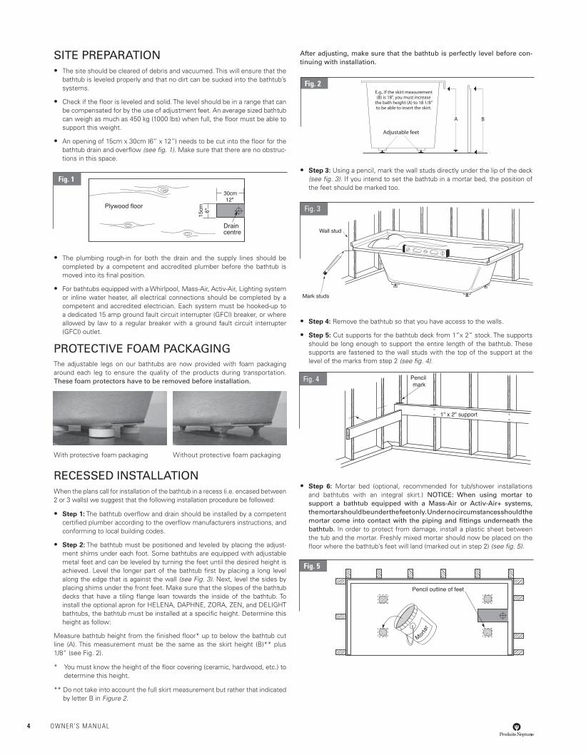
SITE PREPARATION• The site should be cleared of debris and vacuumed. This will ensure that the
bathtub is leveled properly and that no dirt can be sucked into the bathtub’s systems.
• Check if the fl oor is leveled and solid. The level should be in a range that can be compensated for by the use of adjustment feet. An average sized bathtub can weigh as much as 450 kg (1000 lbs) when full, the fl oor must be able to support this weight.
• An opening of 15cm x 30cm (6” x 12”) needs to be cut into the fl oor for the bathtub drain and overfl ow (see fi g. 1). Make sure that there are no obstruc-tions in this space.
• The plumbing rough-in for both the drain and the supply lines should be completed by a competent and accredited plumber before the bathtub is moved into its fi nal position.
• For bathtubs equipped with a Whirlpool, Mass-Air, Activ-Air, Lighting system or inline water heater, all electrical connections should be completed by a competent and accredited electrician. Each system must be hooked-up to a dedicated 15 amp ground fault circuit interrupter (GFCI) breaker, or where allowed by law to a regular breaker with a ground fault circuit interrupter (GFCI) outlet.
PROTECTIVE FOAM PACKAGING The adjustable legs on our bathtubs are now provided with foam packaging around each leg to ensure the quality of the products during transportation. These foam protectors have to be removed before installation.
With protective foam packaging Without protective foam packaging
RECESSED INSTALLATIONWhen the plans call for installation of the bathtub in a recess (i.e. encased between 2 or 3 walls) we suggest that the following installation procedure be followed:
• Step 1: The bathtub overfl ow and drain should be installed by a competent certifi ed plumber according to the overfl ow manufacturers instructions, and conforming to local building codes.
• Step 2: The bathtub must be positioned and leveled by placing the adjust-ment shims under each foot. Some bathtubs are equipped with adjustable metal feet and can be leveled by turning the feet until the desired height is achieved. Level the longer part of the bathtub fi rst by placing a long level along the edge that is against the wall (see Fig. 3). Next, level the sides by placing shims under the front feet. Make sure that the slopes of the bathtub decks that have a tiling fl ange lean towards the inside of the bathtub. To install the optional apron for HELENA, DAPHNE, ZORA, ZEN, and DELIGHT bathtubs, the bathtub must be installed at a specifi c height. Determine this height as follow:
Measure bathtub height from the fi nished fl oor* up to below the bathtub cut line (A). This measurement must be the same as the skirt height (B)** plus 1/8” (see Fig. 2).
* You must know the height of the fl oor covering (ceramic, hardwood, etc.) to determine this height.
** Do not take into account the full skirt measurement but rather that indicated by letter B in Figure 2.
After adjusting, make sure that the bathtub is perfectly level before con-tinuing with installation.
• Step 3: Using a pencil, mark the wall studs directly under the lip of the deck (see fi g. 3). If you intend to set the bathtub in a mortar bed, the position of the feet should be marked too.
• Step 4: Remove the bathtub so that you have access to the walls.
• Step 5: Cut supports for the bathtub deck from 1”x 2” stock. The supports should be long enough to support the entire length of the bathtub. These supports are fastened to the wall studs with the top of the support at the level of the marks from step 2 (see fi g. 4).
• Step 6: Mortar bed (optional, recommended for tub/shower installations and bathtubs with an integral skirt.) NOTICE: When using mortar to support a bathtub equipped with a Mass-Air or Activ-Air+ systems, the mortar should be under the feet only. Under no circumstances should the mortar come into contact with the piping and fi ttings underneath the bathtub. In order to protect from damage, install a plastic sheet between the tub and the mortar. Freshly mixed mortar should now be placed on the fl oor where the bathtub’s feet will land (marked out in step 2) (see fi g. 5).
Fig. 5
Plywood floor
Drain centre
Fig. 4
Adjustable feet
A B
E.g., If the skirt measurement (B) is 18", you must increase
the bath height (A) to 18 1/8" to be able to insert the skirt.
Fig. 2
Fig. 3
Fig. 1
4 OWNER’S MANUAL
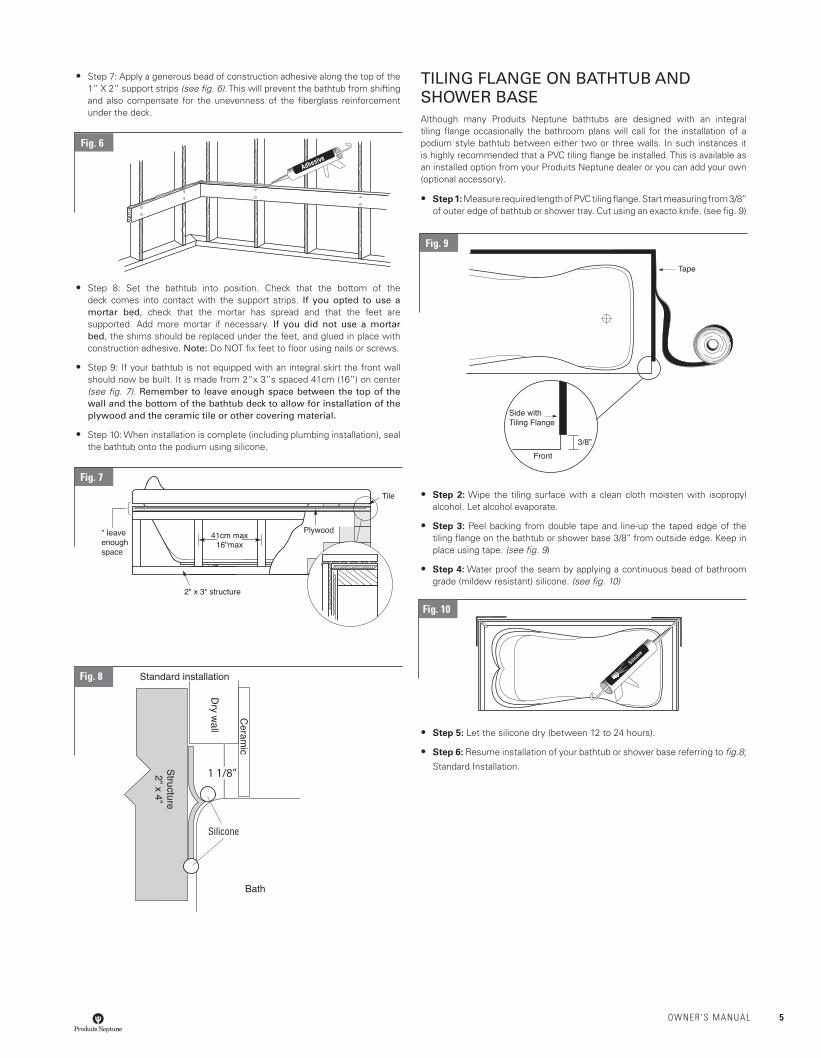
• Step 7: Apply a generous bead of construction adhesive along the top of the 1” X 2” support strips (see fi g. 6). This will prevent the bathtub from shifting and also compensate for the unevenness of the fi berglass reinforcement under the deck.
• Step 8: Set the bathtub into position. Check that the bottom of the deck comes into contact with the support strips. If you opted to use a mortar bed, check that the mortar has spread and that the feet are supported. Add more mortar if necessary. If you did not use a mortar bed, the shims should be replaced under the feet, and glued in place with construction adhesive. Note: Do NOT fi x feet to fl oor using nails or screws.
• Step 9: If your bathtub is not equipped with an integral skirt the front wall should now be built. It is made from 2”x 3”s spaced 41cm (16”) on center (see fi g. 7). Remember to leave enough space between the top of the wall and the bottom of the bathtub deck to allow for installation of the plywood and the ceramic tile or other covering material.
• Step 10: When installation is complete (including plumbing installation), seal the bathtub onto the podium using silicone.
TILING FLANGE ON BATHTUB AND SHOWER BASEAlthough many Produits Neptune bathtubs are designed with an integral tiling fl ange occasionally the bathroom plans will call for the installation of a podium style bathtub between either two or three walls. In such instances it is highly recommended that a PVC tiling fl ange be installed. This is available as an installed option from your Produits Neptune dealer or you can add your own (optional accessory).
• Step 1: Measure required length of PVC tiling fl ange. Start measuring from 3/8’’ of outer edge of bathtub or shower tray. Cut using an exacto knife. (see fi g. 9)
• Step 2: Wipe the tiling surface with a clean cloth moisten with isopropyl alcohol. Let alcohol evaporate.
• Step 3: Peel backing from double tape and line-up the taped edge of the tiling fl ange on the bathtub or shower base 3/8’’ from outside edge. Keep in place using tape. (see fi g. 9)
• Step 4: Water proof the seam by applying a continuous bead of bathroom grade (mildew resistant) silicone. (see fi g. 10)
• Step 5: Let the silicone dry (between 12 to 24 hours).
• Step 6: Resume installation of your bathtub or shower base referring to fi g.8;
Standard Installation.
Silicone
1 1/8”
Fig. 10
Fig. 8
Fig. 7
Fig. 9
Fig. 6
OWNER’S MANUAL 5
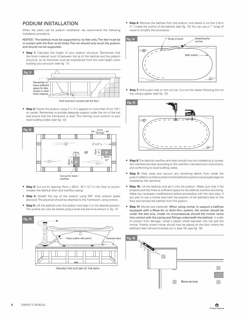
PODIUM INSTALLATIONWhen the plans call for podium installation we recommend the following installation procedure:
NOTICE: The bathtub must be supported by its feet only. The feet must be in contact with the fl oor at all times. The rim should only touch the podium and should not be supported.
• Step 1: Calculate the height of your podium structure. Remember that the fi nish material must fi t between the lip of the bathtub and the podium structure, so its thickness must be substracted from the total height when building your structure (see fi g. 11).
• Step 2: Frame the podium using 2”x 3”s spaced no more than 41cm (16”) on center. Remember to provide adequate support under the rim of the tub and ensure that the framework is level. This framing must conform to your local building codes (see fi g. 12).
• Step 3: Cut out an opening 15cm x 30cm (6”x 12”) in the fl oor to accom-modate the bathtub drain and overfl ow piping.
• Step 4: Sheath the top of the podium using 5/8” thick exterior grade plywood. The plywood should be attached to the framework using screws.
• Step 5: Lift the bathtub onto the podium and align it in the desired position. The outline can now be traced using a level and pencil as shown in fi g. 13.
• Step 6: Remove the bathtub from the podium, and sketch a cut line 2.5cm (1”) inside the outline of the bathtub (see fi g. 14). You can use a 1” scrap of wood to simplify this procedure.
• Step 7: Drill a pilot hole on the cut line. Cut out the waste following the cut line using a jigsaw (see fi g. 15).
• Step 8: The bathtub overfl ow and drain should now be installed by a compe-tent certifi ed plumber according to the overfl ow manufacturers instructions, and conforming to local building codes.
• Step 9: Clear away and vacuum any remaining debris from inside the podium (debris could be sucked into the bathtub’s systems causing damage not covered by the warranty).
• Step 10: Lift the bathtub and set it into the podium. Make sure that it fi ts properly and that there is suffi cient space for the bathtub overfl ow plumbing. Make any necessary modifi cations before proceeding with the next step. If you plan to use a mortar bed mark the position of the bathtub’s feet on the fl oor and remove the bathtub from the podium.
• Step 11: Mortar bed (optional). When using mortar to support a bathtub equipped with a Mass-Air or Activ-Air+ system, the mortar should be under the feet only. Under no circumstances should the mortar come into contact with the piping and fi ttings underneath the bathtub. In order to protect from damage, install a plastic sheet between the tub and the mortar. Freshly mixed mortar should now be placed on the fl oor where the bathtub’s feet will land (marked out in step 10) (see fi g. 16).
or
Blocs de bois
Fig. 13
Fig. 12
Fig. 11
Fig. 14
Fig. 15
Fig. 16
6 OWNER’S MANUAL
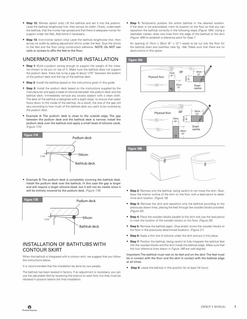
• Step 12: (Mortar option only) Lift the bathtub and set it into the podium. Level the bathtub lengthwise fi rst, then across its width. Check, underneath the bathtub, that the mortar has spread and that there is adequate mortar for support under the feet. Add some if necessary.
• Step 13: (non-mortar option only) Level the bathtub lengthwise fi rst, then across its width by adding adjustment shims under the feet. Glue the shims to the feet and the fl oor using construction adhesive. NOTE: Do NOT use nails or screws to affi x the feet to the fl oor.
UNDERMOUNT BATHTUB INSTALLATION• Step 1: Build a podium strong enough to support the weight of the mate-
rial chosen to be put on top of it. Make sure the bathtub does not support the podium deck: there has to be a gap of about 1/16” between the bottom of the podium deck and the top of the bathtub deck.
• Step 2: Install the bathtub based on the instructions given in this guide.
• Step 3: Install the podium deck based on the instructions supplied by the manufacturer and apply a bead of silicone between the podium deck and the bathtub deck. Immediately remove any excess sealant with a clean cloth. The deck of the bathtub is designed with a slight slope, to ensure that water fl ows down to the inside of the bathtub. As a result, the size of the gap will vary according to how much of the bathtub deck you want to be covered by the podium deck.
• Example A: The podium deck is close to the outside edge. The gap between the podium deck and the bathtub deck is narrow; install the podium deck over the bathtub and apply a small bead of silicone caulk. (Figure 17A)
• Exemple B: The podium deck is completely covering the bathtub deck. Install the podium deck over the bathtub. In this case the gap is larger and will require a larger silicone bead, but it will not be visible since it will be entirely covered by the podium deck. (Figure 17B)
INSTALLATION OF BATHTUBS WITH CONTOUR SKIRTWhen the bathtub is integrated with a contour skirt, we suggest that you follow the instructions below.
It is recommended that the installation be done by two people.
The bathtub has been leveled in factory. If an adjustment is necessary, you can use the adjustable feet by loosening the locknut on each foot, but they must be relocked in position before the fi nal installation.
• Step 1: Temporarily position the entire bathtub in the desired location. If the drain is not preinstalled, mark its location on the fl oor so that you can reposition the bathtub correctly in the following steps (Figure 18A). Using a washable marker, draw two lines from the edge of the bathtub to the skirt (Figure 18B) to establish a reference point for Step 7.
An opening of 15cm x 30cm (6” x 12”) needs to be cut into the fl oor for the bathtub drain and overfl ow (see fi g. 18a). Make sure that there are no obstructions in this space.
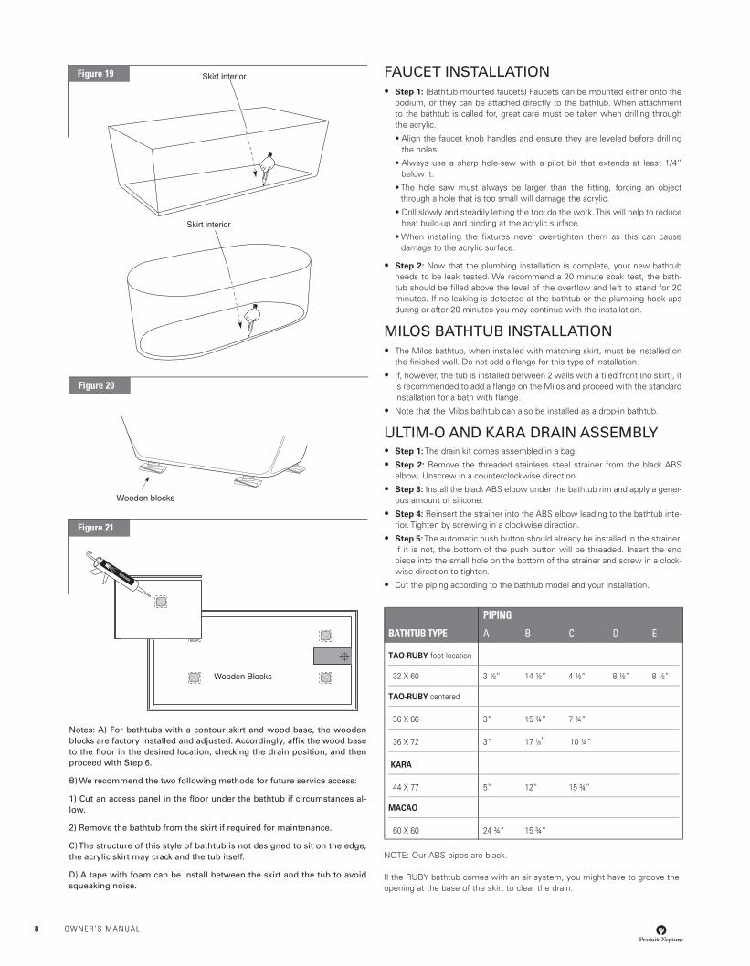
• Step 2: Remove only the bathtub, being careful to not move the skirt. Next, draw the interior outline of the skirt on the fl oor with a lead pencil to deter-mine skirt location. (Figure 19)
• Step 3: Remove the skirt and reposition only the bathtub according to the previously drawn lines, placing the feet through the wooden blocks provided. (Figure 20)
• Step 4: Place the wooden blocks parallel to the skirt and use the lead pencil to mark the location of the wooden blocks on the fl oor. (Figure 20)
• Step 5: Remove the bathtub again. Glue and/or screw the wooden blocks to the fl oor in the previously determined locations. (Figure 21)
• Step 6: Apply a thin line of silicone under the skirt and put it into place.
• Step 7: Position the bathtub, being careful to fully integrate the bathtub feet into the wooden blocks and the skirt inside the bathtub edge. Make sure that the two reference lines drawn in Figure 18B are well aligned.
Important: The bathtub must rest on its feet and on the skirt. The feet must be in contact with the fl oor and the skirt in contact with the bathtub edge at all times.
• Step 8: Leave the bathtub in this position for at least 24 hours.
Figure 18B
orPlywood floor
Drain centre
Plywood floor
or
Drain centre
Podium deck
Silicon
Bathtub deck
1/16”
Figure 17A
Podium deck
Silicon
Bathtub deck
1/16”
Figure 17B
Figure 18A
OWNER’S MANUAL 7
Notes: A) For bathtubs with a contour skirt and wood base, the wooden blocks are factory installed and adjusted. Accordingly, affi x the wood base to the fl oor in the desired location, checking the drain position, and then proceed with Step 6.
B) We recommend the two following methods for future service access:
1) Cut an access panel in the fl oor under the bathtub if circumstances al-low.
2) Remove the bathtub from the skirt if required for maintenance.
C) The structure of this style of bathtub is not designed to sit on the edge, the acrylic skirt may crack and the tub itself.
D) A tape with foam can be install between the skirt and the tub to avoid squeaking noise.
FAUCET INSTALLATION• Step 1: (Bathtub mounted faucets) Faucets can be mounted either onto the
podium, or they can be attached directly to the bathtub. When attachment to the bathtub is called for, great care must be taken when drilling through the acrylic.
• Align the faucet knob handles and ensure they are leveled before drilling the holes.
• Always use a sharp hole-saw with a pilot bit that extends at least 1/4” below it.
• The hole saw must always be larger than the fi tting, forcing an object through a hole that is too small will damage the acrylic.
• Drill slowly and steadily letting the tool do the work. This will help to reduce heat build-up and binding at the acrylic surface.
• When installing the fi xtures never over-tighten them as this can cause damage to the acrylic surface.
• Step 2: Now that the plumbing installation is complete, your new bathtub needs to be leak tested. We recommend a 20 minute soak test, the bath-tub should be fi lled above the level of the overfl ow and left to stand for 20 minutes. If no leaking is detected at the bathtub or the plumbing hook-ups during or after 20 minutes you may continue with the installation.
MILOS BATHTUB INSTALLATION• The Milos bathtub, when installed with matching skirt, must be installed on
the fi nished wall. Do not add a fl ange for this type of installation.
• If, however, the tub is installed between 2 walls with a tiled front (no skirt), it is recommended to add a fl ange on the Milos and proceed with the standard installation for a bath with fl ange.
• Note that the Milos bathtub can also be installed as a drop-in bathtub.
ULTIM-O AND KARA DRAIN ASSEMBLY• Step 1: The drain kit comes assembled in a bag.
• Step 2: Remove the threaded stainless steel strainer from the black ABS elbow. Unscrew in a counterclockwise direction.
• Step 3: Install the black ABS elbow under the bathtub rim and apply a gener-ous amount of silicone.
• Step 4: Reinsert the strainer into the ABS elbow leading to the bathtub inte-rior. Tighten by screwing in a clockwise direction.
• Step 5: The automatic push button should already be installed in the strainer. If it is not, the bottom of the push button will be threaded. Insert the end piece into the small hole on the bottom of the strainer and screw in a clock-wise direction to tighten.
• Cut the piping according to the bathtub model and your installation.
NOTE: Our ABS pipes are black.
Il the RUBY bathtub comes with an air system, you might have to groove the opening at the base of the skirt to clear the drain.
PIPING
BATHTUB TYPE A B C D E
TAO-RUBY foot location
32 X 60 3 ½” 14 ½” 4 ½” 8 ½” 8 ½”
TAO-RUBY centered
36 X 66 3” 15 ¾” 7 ¾”
36 X 72 3” 17 1/8” 10 ¼”
KARA
44 X 77 5” 12” 15 ¾”
MACAO
60 X 60 24 ¾” 15 ¾”
Wooden blocks
Wooden Blocks
Skirt interior
Skirt interior
Figure 19
Figure 20
Figure 21
8 OWNER’S MANUAL
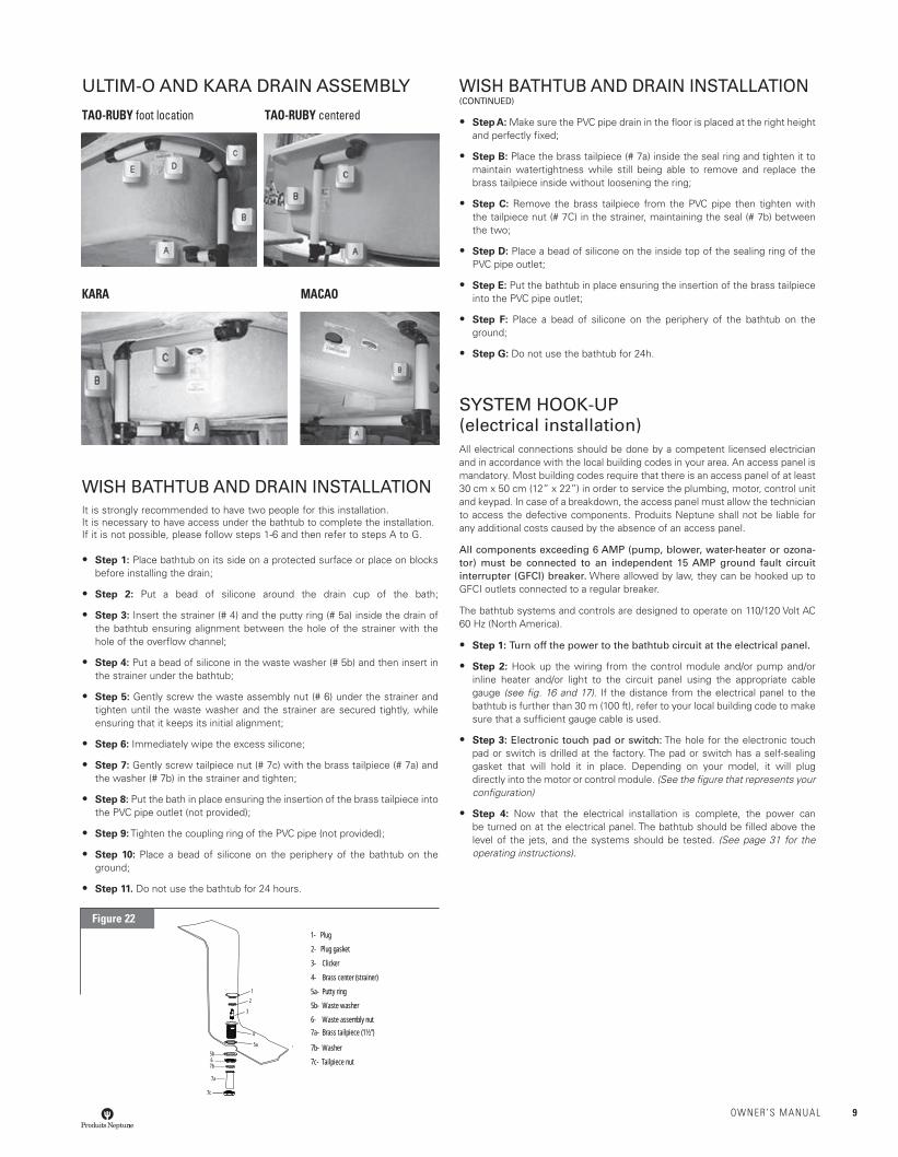
ULTIM-O AND KARA DRAIN ASSEMBLY
TAO-RUBY foot location TAO-RUBY centered
KARA MACAO
WISH BATHTUB AND DRAIN INSTALLATIONIt is strongly recommended to have two people for this installation.It is necessary to have access under the bathtub to complete the installation. If it is not possible, please follow steps 1-6 and then refer to steps A to G.
• Step 1: Place bathtub on its side on a protected surface or place on blocks before installing the drain;
• Step 2: Put a bead of silicone around the drain cup of the bath;
• Step 3: Insert the strainer (# 4) and the putty ring (# 5a) inside the drain of the bathtub ensuring alignment between the hole of the strainer with the hole of the overfl ow channel;
• Step 4: Put a bead of silicone in the waste washer (# 5b) and then insert in the strainer under the bathtub;
• Step 5: Gently screw the waste assembly nut (# 6) under the strainer and tighten until the waste washer and the strainer are secured tightly, while ensuring that it keeps its initial alignment;
• Step 6: Immediately wipe the excess silicone;
• Step 7: Gently screw tailpiece nut (# 7c) with the brass tailpiece (# 7a) and the washer (# 7b) in the strainer and tighten;
• Step 8: Put the bath in place ensuring the insertion of the brass tailpiece into the PVC pipe outlet (not provided);
• Step 9: Tighten the coupling ring of the PVC pipe (not provided);
• Step 10: Place a bead of silicone on the periphery of the bathtub on the ground;
• Step 11. Do not use the bathtub for 24 hours.
WISH BATHTUB AND DRAIN INSTALLATION(CONTINUED)
• Step A: Make sure the PVC pipe drain in the fl oor is placed at the right height and perfectly fi xed;
• Step B: Place the brass tailpiece (# 7a) inside the seal ring and tighten it to maintain watertightness while still being able to remove and replace the brass tailpiece inside without loosening the ring;
• Step C: Remove the brass tailpiece from the PVC pipe then tighten with the tailpiece nut (# 7C) in the strainer, maintaining the seal (# 7b) between the two;
• Step D: Place a bead of silicone on the inside top of the sealing ring of the PVC pipe outlet;
• Step E: Put the bathtub in place ensuring the insertion of the brass tailpiece into the PVC pipe outlet;
• Step F: Place a bead of silicone on the periphery of the bathtub on the ground;
• Step G: Do not use the bathtub for 24h.
SYSTEM HOOK-UP(electrical installation)All electrical connections should be done by a competent licensed electrician and in accordance with the local building codes in your area. An access panel is mandatory. Most building codes require that there is an access panel of at least 30 cm x 50 cm (12” x 22”) in order to service the plumbing, motor, control unit and keypad. In case of a breakdown, the access panel must allow the technician to access the defective components. Produits Neptune shall not be liable for any additional costs caused by the absence of an access panel.
All components exceeding 6 AMP (pump, blower, water-heater or ozona-tor) must be connected to an independent 15 AMP ground fault circuit interrupter (GFCI) breaker. Where allowed by law, they can be hooked up to GFCI outlets connected to a regular breaker.
The bathtub systems and controls are designed to operate on 110/120 Volt AC 60 Hz (North America).
• Step 1: Turn off the power to the bathtub circuit at the electrical panel.
• Step 2: Hook up the wiring from the control module and/or pump and/or inline heater and/or light to the circuit panel using the appropriate cable gauge (see fi g. 16 and 17). If the distance from the electrical panel to the bathtub is further than 30 m (100 ft), refer to your local building code to make sure that a suffi cient gauge cable is used.
• Step 3: Electronic touch pad or switch: The hole for the electronic touch pad or switch is drilled at the factory. The pad or switch has a self-sealing gasket that will hold it in place. Depending on your model, it will plug directly into the motor or control module. (See the fi gure that represents your confi guration)
• Step 4: Now that the electrical installation is complete, the power can be turned on at the electrical panel. The bathtub should be fi lled above the level of the jets, and the systems should be tested. (See page 31 for the operating instructions).
1- Plug
2- Plug gasket 3- Clicker 4- Brass center (strainer) 5a- Putty ring 5b- Waste washer 6- Waste assembly nut 7a- Brass tailpiece (1½")
7b- Washer 7c- Tailpiece nut
1
2
3
4
5a
5b67b
7a
7c
Figure 22
OWNER’S MANUAL 9
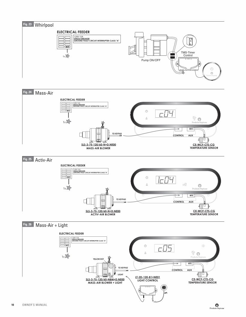
Mass-AirFig. 24
Activ-AirFig. 25
Mass-Air + LightFig. 26
Fig. 23 Whirlpool
10 OWNER’S MANUAL
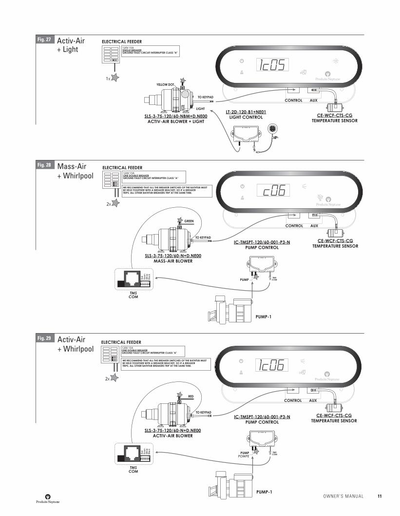
Activ-Air + Light
Fig. 27
Mass-Air + Whirlpool
Fig. 28
Activ-Air + Whirlpool
Fig. 29
Red
Gree
nW
hite
Blac
k
Red
Gree
nW
hite
Blac
k
OWNER’S MANUAL 11
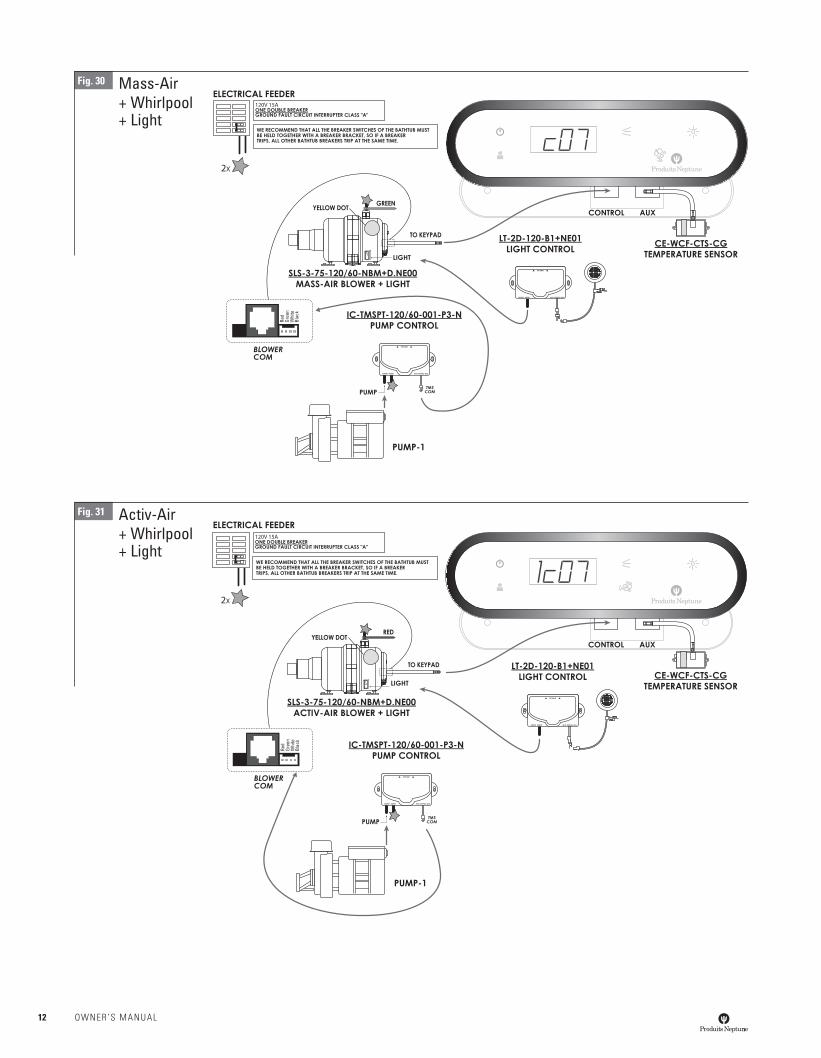
Mass-Air + Whirlpool+ Light
Fig. 30
Activ-Air + Whirlpool+ Light
Fig. 31
Red
Gree
nW
hite
Blac
k
Red
Gree
nW
hite
Blac
k
12 OWNER’S MANUAL
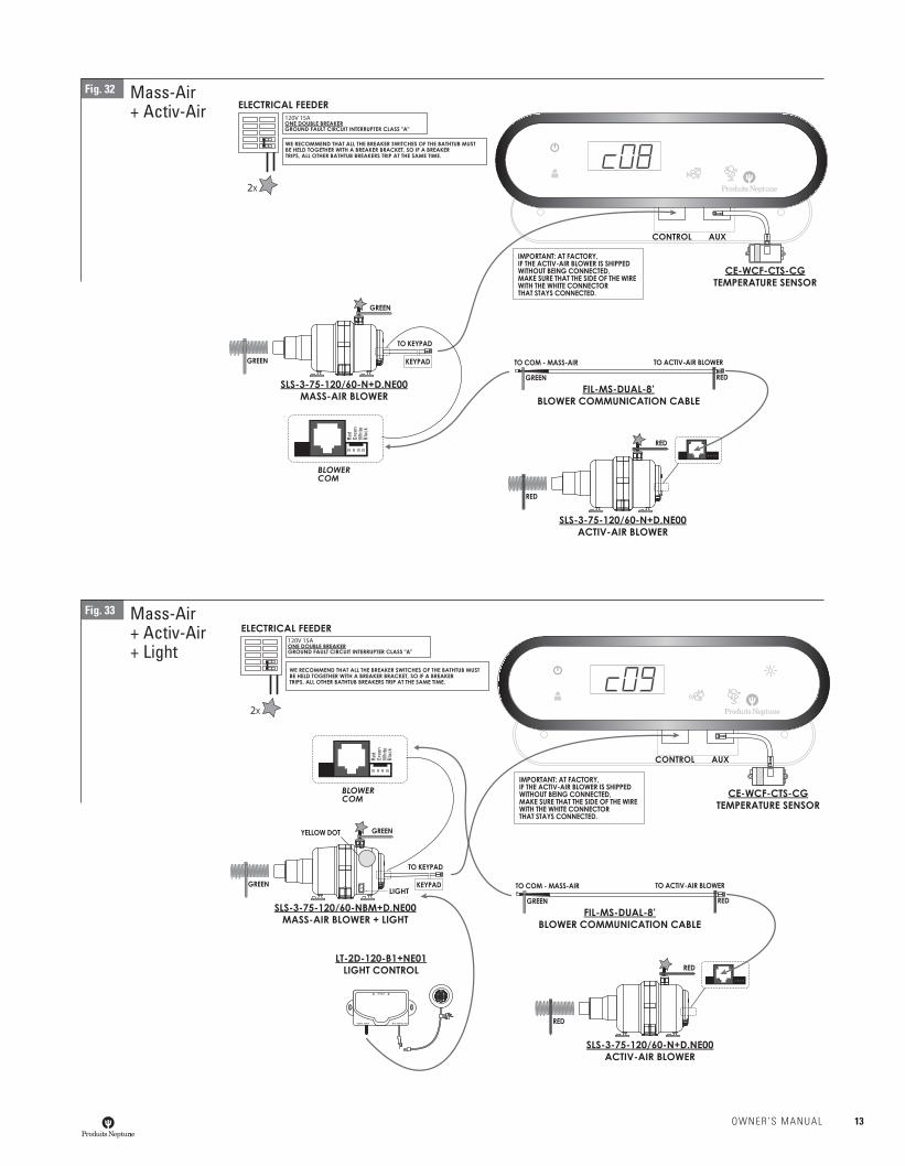
Mass-Air + Activ-Air
Fig. 32
Mass-Air + Activ-Air+ Light
Fig. 33
Red
Gree
nW
hite
Blac
kRe
dGr
een
Whi
teBl
ack
OWNER’S MANUAL 13
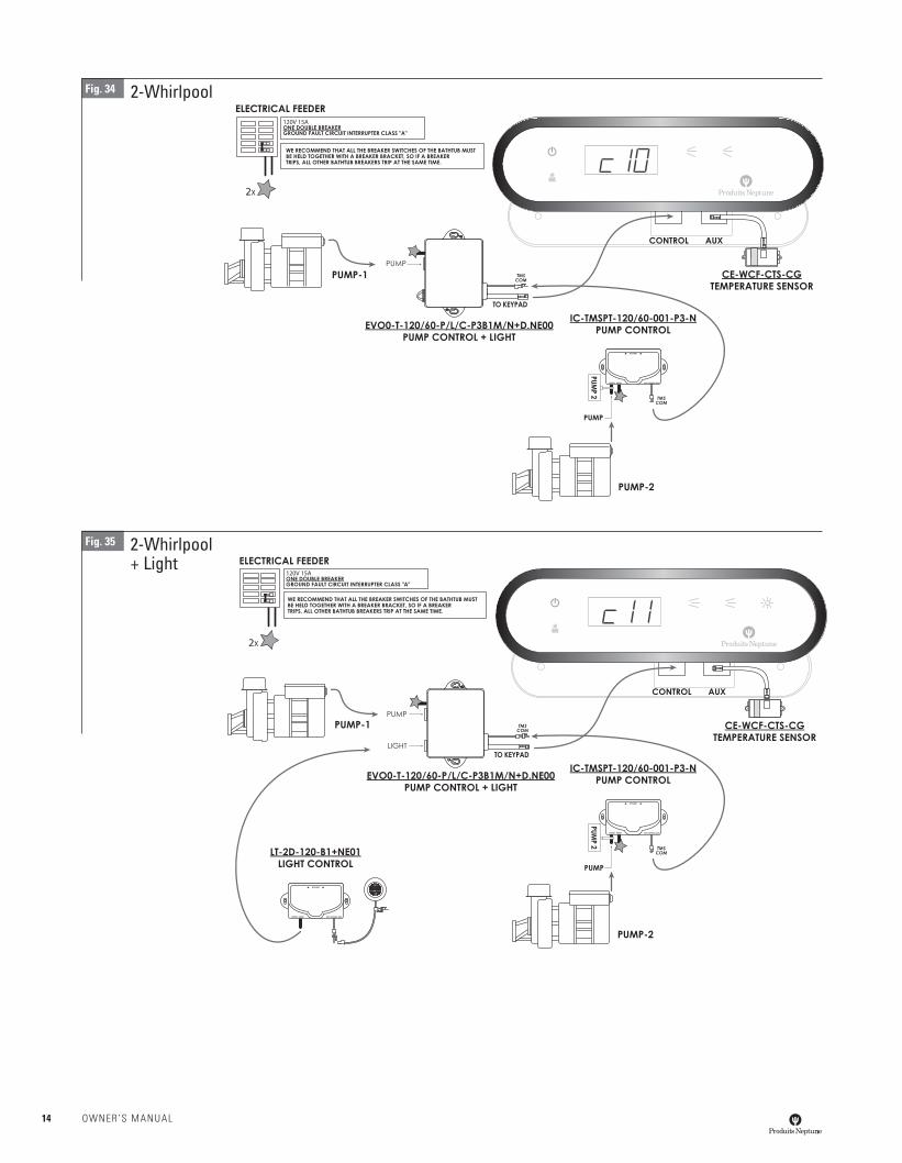
2-WhirlpoolFig. 34
Fig. 35 2-Whirlpool+ Light
14 OWNER’S MANUAL
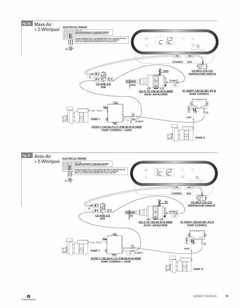
Mass-Air+ 2-Whirlpool
Activ-Air+ 2-Whirlpool
Fig. 37
Fig. 36
OWNER’S MANUAL 15
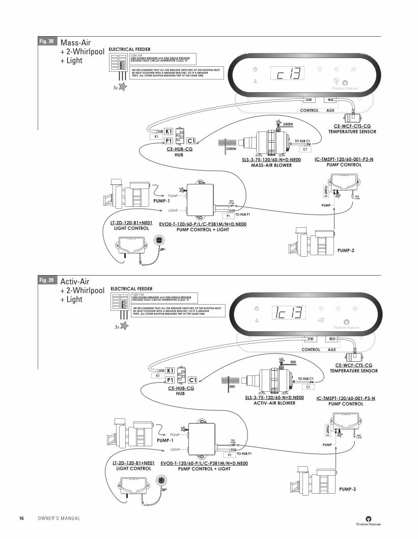
Fig. 38
Fig. 39
Mass-Air+ 2-Whirlpool+ Light
Activ-Air+ 2-Whirlpool+ Light
16 OWNER’S MANUAL
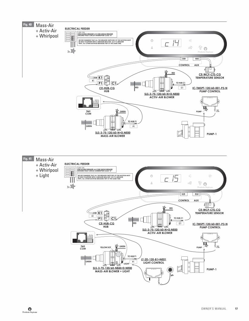
Mass-Air+ Activ-Air+ Whirlpool
Fig. 40
Mass-Air+ Activ-Air+ Whirlpool+ Light
Fig. 41
Red
Gree
nW
hite
Blac
k
Red
Gree
nW
hite
Blac
k
OWNER’S MANUAL 17
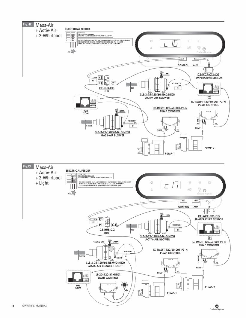
Fig. 42
Fig.43
Mass-Air+ Activ-Air+ 2-Whirlpool
Mass-Air+ Activ-Air+ 2-Whirlpool+ Light
Red
Gree
nW
hite
Blac
k
Red
Gree
nW
hite
Blac
k
Red
Gree
nW
hite
Blac
k
Red
Gree
nW
hite
Blac
k
18 OWNER’S MANUAL
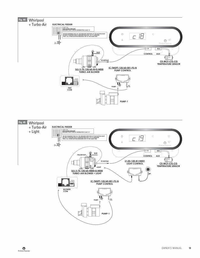
Whirlpool+ Turbo-Air
Fig. 44
Whirlpool+ Turbo-Air+ Light
Fig. 45
Red
Gree
nW
hite
Blac
k
Red
Gree
nW
hite
Blac
k
OWNER’S MANUAL 19
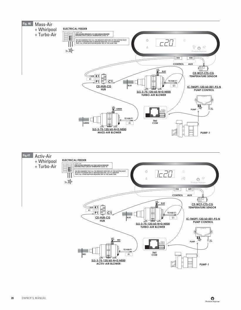
Mass-Air+ Whirlpool+ Turbo-Air
Fig. 46
Activ-Air+ Whirlpool+ Turbo-Air
Fig.47 Re
dGr
een
Whi
teBl
ack
Red
Gree
nW
hite
Blac
k
20 OWNER’S MANUAL
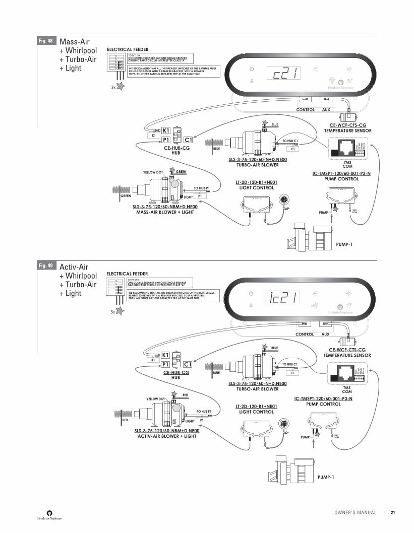
Mass-Air+ Whirlpool+ Turbo-Air+ Light
Fig. 48
Activ-Air+ Whirlpool+ Turbo-Air+ Light
Fig. 49
Red
Gree
nW
hite
Blac
k
Red
Gree
nW
hite
Blac
k
OWNER’S MANUAL 21
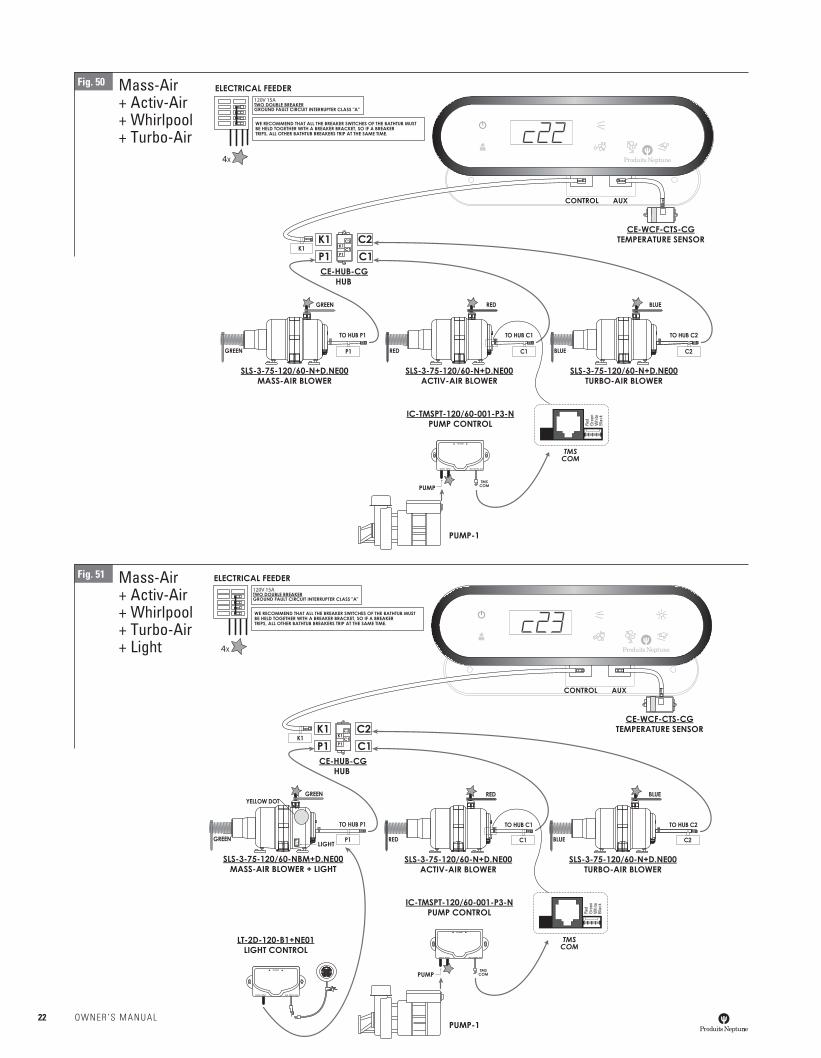
Mass-Air+ Activ-Air+ Whirlpool+ Turbo-Air
Fig. 50
Mass-Air+ Activ-Air+ Whirlpool+ Turbo-Air+ Light
Fig. 51Re
dGr
een
Whi
teBl
ack
Red
Gree
nW
hite
Blac
k
22 OWNER’S MANUAL
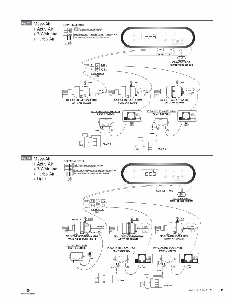
Fig. 52 Mass-Air+ Activ-Air+ 2-Whirlpool+ Turbo-Air
Fig. 53 Mass-Air+ Activ-Air+ 2-Whirlpool+ Turbo-Air+ Light
Red
Gree
nW
hite
Blac
k
Red
Gree
nW
hite
Blac
k
Red
Gree
nW
hite
Blac
k
Red
Gree
nW
hite
Blac
k
OWNER’S MANUAL 23
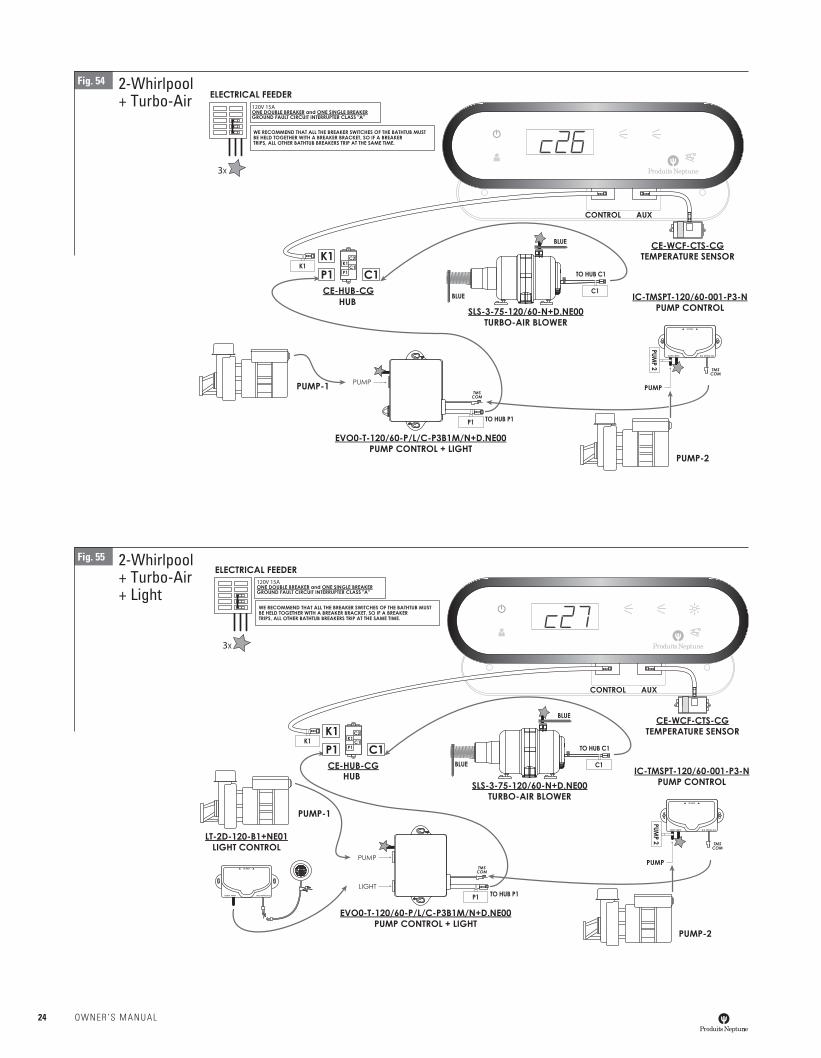
Fig. 54 2-Whirlpool+ Turbo-Air
Fig. 55 2-Whirlpool+ Turbo-Air+ Light
24 OWNER’S MANUAL
Red
Gree
nW
hite
Blac
k
Red
Gree
nW
hite
Blac
k
Red
Gree
nW
hite
Blac
k
Red
Gree
nW
hite
Blac
k
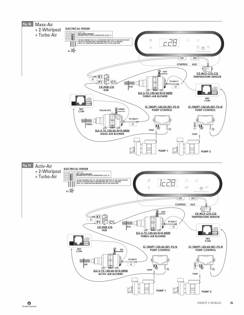
Fig. 56 Mass-Air+ 2-Whirlpool+ Turbo-Air
Fig. 57 Activ-Air+ 2-Whirlpool+ Turbo-Air
OWNER’S MANUAL 25
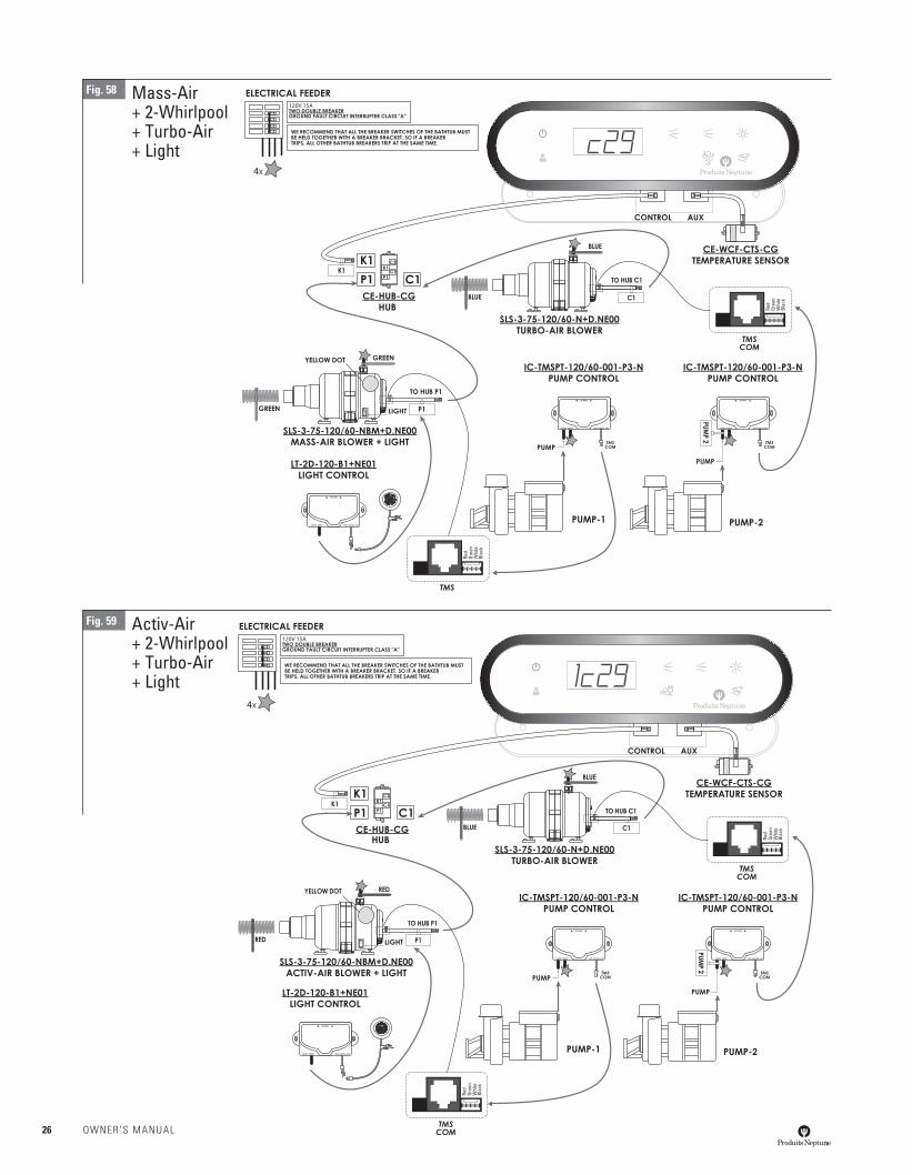
Mass-Air+ 2-Whirlpool+ Turbo-Air+ Light
Fig. 58
Activ-Air+ 2-Whirlpool+ Turbo-Air+ Light
Fig. 59
Red
Gree
nW
hite
Blac
k
Red
Gree
nW
hite
Blac
k
Red
Gree
nW
hite
Blac
k
Red
Gree
nW
hite
Blac
k
26 OWNER’S MANUAL
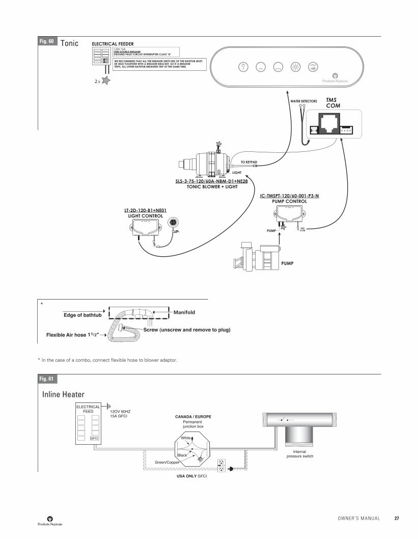
Fig. 61
Inline Heater
* In the case of a combo, connect fl exible hose to blower adaptor.
TonicFig. 60
*
OWNER’S MANUAL 27
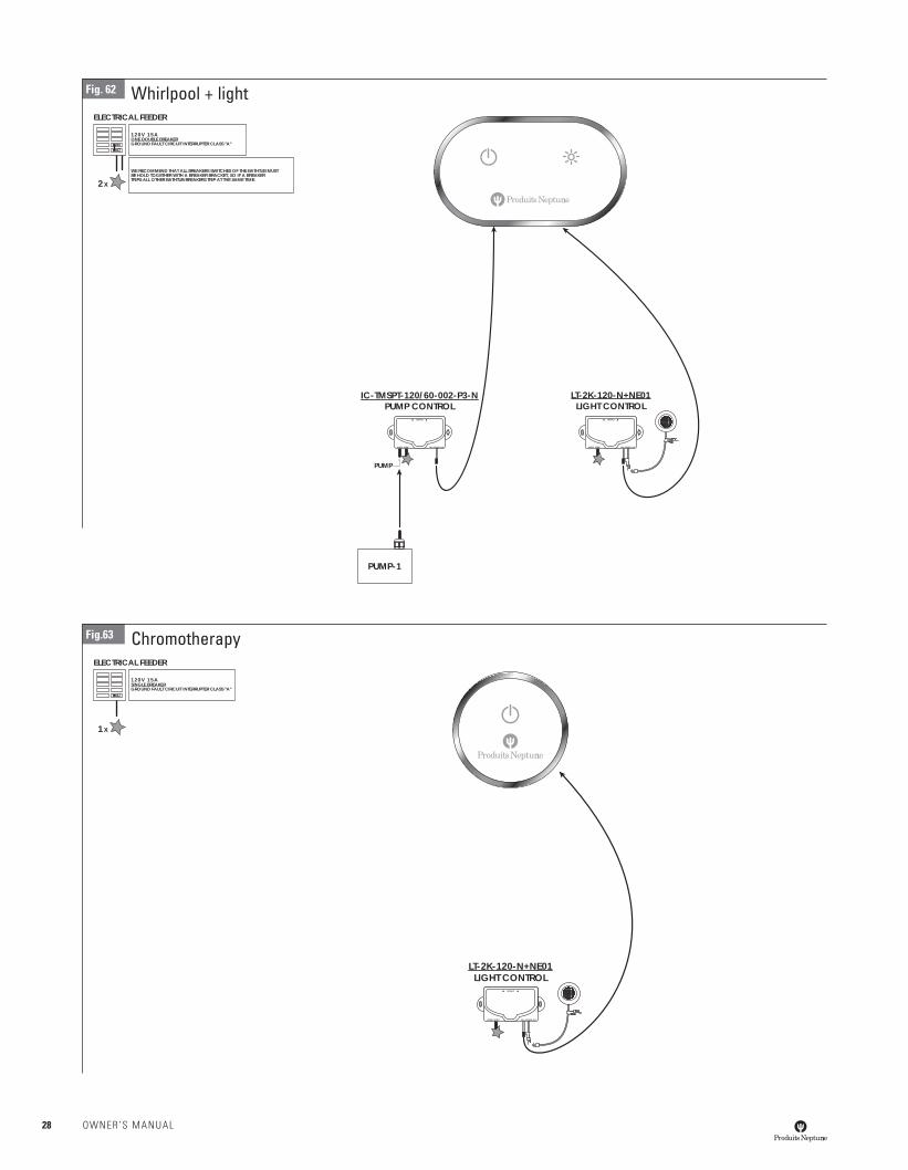
Whirlpool + lightFig. 62
120V 15AONE DOUBLE BREAKERGROUND FAULT CIRCUIT INTERRUPTER CLASS "A"
2X
WE RECOMMEND THAT ALL BREAKERS SWITCHES OF THE BATHTUB MUSTBE HOLD TOGETHER WITH A BREAKER BRACKET, SO IF A BREAKERTRIPS ALL OTHER BATHTUB BREAKERS TRIP AT THE SAME TIME.
ELECTRICAL FEEDER
PUMP-1
IC-TMSPT-120/60-002-P3-NPUMP CONTROL
OUTPUT INTPUT
UP/HAUT
PUMP
W/D KEYPAD AUX
LT-2K-120-N+NE01LIGHT CONTROL
OUTPUT INTPUT
UP/HAUT
W/D KEYPAD AUX
ChromotherapyFig.63
120V 15ASINGLE BREAKERGROUND FAULT CIRCUIT INTERRUPTER CLASS "A"
1X
ELECTRICAL FEEDER
LT-2K-120-N+NE01LIGHT CONTROL
OUTPUT INTPUT
UP/HAUT
W/D KEYPAD AUX
28 OWNER’S MANUAL
Ozonator
TAMING THE ELEMENTSHygiene has always been a main concern for the consumer when purchasing a bathtub with a massage system, and it has always been our main concern when we develop any new product. Up till now, no one had found the solution to tame nature’s special elements in a way that is safe and practical for use in the bathtub industry while taking full advantage of the powerful oxidizing and disinfecting properties of ozone in a whirlpool or an air system.
BASICALLY, YOU DON’T WANT TO BE DISINFECTED, YOU WANT YOUR BATHTUB SYSTEM TO BE DISINFECTEDIt was essential to us to fi nd a way to thoroughly sanitize the entire bathtub system, whether it be whirlpool or air channel system without necessarily having the bather caught in the middle like in the method currently used in the bathtub industry. The majority of ozonators available on the market function with the venturi effect of the whirlpool pump to inject the ozone within the system. Therefore the bathtub must be full of water and the whirlpool system must be in function. The ozone that is injected within the system loses most of its effi ciency for the sanitization of the piping of the whirlpool system because the majority of the ozone concentration is used to sanitize the bathtub water. Furthermore, a venturi system is incapable of generating as much concentration of ozone as with a compressor system.
IT IS THE SYSTEM THAT WE ARE SANITIZING, NOT THE BATHERThe O3 System eliminates this worrisome factor by completely sanitizing every inch of the air channel and/or whirlpool piping immediately after each use thus preventing the possible colonization of bacteria and micro-organisms.
Even though ozone is not a harmful gas when used in such a small concentra-tion for bathtub sanitization, we have made it so that the system will only start under certain conditions and it will never be possible to start otherwise. How our system works:
- When the probes detect water in the bathtub, the O3 System automatically activates the waiting mode until the bathtub is emptied.
- Once the O3 System has detected an absence of water, the O3 System turns on a one hour delay timer. The O3 System will then start the cleaning process for a period of 15 minutes to sanitize the whirlpool piping and/or the air channel of your bathtub massage system.
- When the sanitization cycle is fi nished, the O3 System will automatically turn off until another water detection occurs within the bathtub.
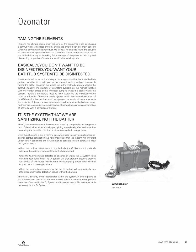
There are 2 security levels incorporated within the system. A loop of piping at the module level and a security check-valve. These 2 security levels prevent water backfl ow within the O3 System and its components. No maintenance is necessary for the O3 System. GFCI Breaker
15A /120v
OWNER’S MANUAL 29
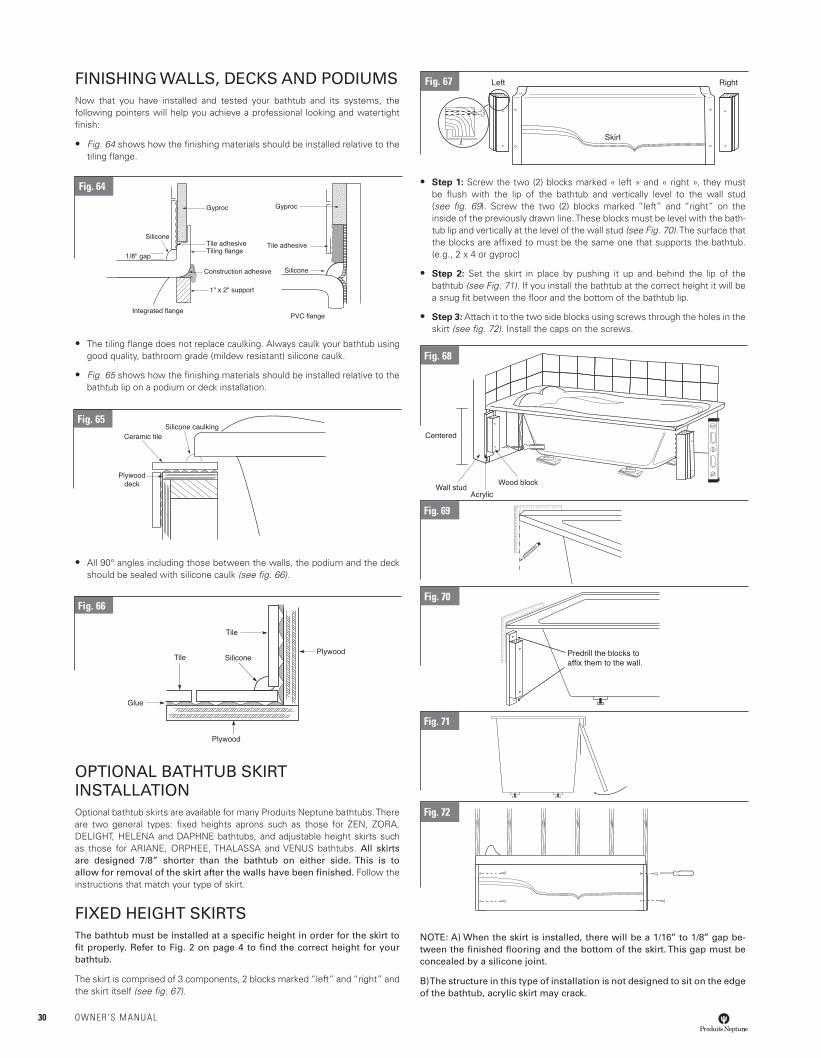
FINISHING WALLS, DECKS AND PODIUMSNow that you have installed and tested your bathtub and its systems, the following pointers will help you achieve a professional looking and watertight fi nish:
• Fig. 64 shows how the fi nishing materials should be installed relative to the tiling fl ange.
• The tiling fl ange does not replace caulking. Always caulk your bathtub using good quality, bathroom grade (mildew resistant) silicone caulk.
• Fig. 65 shows how the fi nishing materials should be installed relative to the bathtub lip on a podium or deck installation.
• All 90° angles including those between the walls, the podium and the deck should be sealed with silicone caulk (see fi g. 66).
OPTIONAL BATHTUB SKIRT INSTALLATIONOptional bathtub skirts are available for many Produits Neptune bathtubs. There are two general types: fi xed heights aprons such as those for ZEN, ZORA, DELIGHT, HELENA and DAPHNE bathtubs, and adjustable height skirts such as those for ARIANE, ORPHEE, THALASSA and VENUS bathtubs. All skirts are designed 7/8” shorter than the bathtub on either side. This is to allow for removal of the skirt after the walls have been fi nished. Follow the instructions that match your type of skirt.
FIXED HEIGHT SKIRTSThe bathtub must be installed at a specifi c height in order for the skirt to fi t properly. Refer to Fig. 2 on page 4 to fi nd the correct height for your bathtub.
The skirt is comprised of 3 components, 2 blocks marked “left” and “right” and the skirt itself (see fi g. 67).
• Step 1: Screw the two (2) blocks marked « left » and « right », they must be fl ush with the lip of the bathtub and vertically level to the wall stud (see fi g. 69). Screw the two (2) blocks marked “left” and “right” on the inside of the previously drawn line. These blocks must be level with the bath-tub lip and vertically at the level of the wall stud (see Fig. 70). The surface that the blocks are affi xed to must be the same one that supports the bathtub. (e.g., 2 x 4 or gyproc)
• Step 2: Set the skirt in place by pushing it up and behind the lip of the bathtub (see Fig. 71). If you install the bathtub at the correct height it will be a snug fi t between the fl oor and the bottom of the bathtub lip.
• Step 3: Attach it to the two side blocks using screws through the holes in the skirt (see fi g. 72). Install the caps on the screws.
NOTE: A) When the skirt is installed, there will be a 1/16’’ to 1/8’’ gap be-tween the fi nished fl ooring and the bottom of the skirt. This gap must be concealed by a silicone joint.
B) The structure in this type of installation is not designed to sit on the edge of the bathtub, acrylic skirt may crack.
Fig. 71
Fig. 72
Predrill the blocks to affix them to the wall.
Fig. 70
Fig. 67
Fig. 66
Fig. 65
Fig. 64
Fig. 68
Fig. 69
30 OWNER’S MANUAL
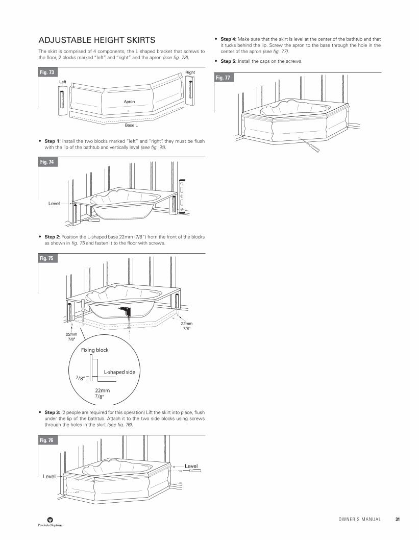
ADJUSTABLE HEIGHT SKIRTSThe skirt is comprised of 4 components, the L shaped bracket that screws to the fl oor, 2 blocks marked “left” and “right” and the apron (see fi g. 73).
• Step 1: Install the two blocks marked “left” and “right”, they must be fl ush with the lip of the bathtub and vertically level (see fi g. 74).
• Step 2: Position the L-shaped base 22mm (7/8”) from the front of the blocks as shown in fi g. 75 and fasten it to the fl oor with screws.
• Step 3: (2 people are required for this operation) Lift the skirt into place, fl ush under the lip of the bathtub. Attach it to the two side blocks using screws through the holes in the skirt (see fi g. 76).
• Step 4: Make sure that the skirt is level at the center of the bathtub and that it tucks behind the lip. Screw the apron to the base through the hole in the center of the apron (see fi g. 77).
• Step 5: Install the caps on the screws.
Fig. 77
Level
Fixing block
L-shaped side
22mm7/8”
7/8”
Level
Level
Fig. 73
Fig. 74
Fig. 75
Fig. 76
OWNER’S MANUAL 31
Operating instruction
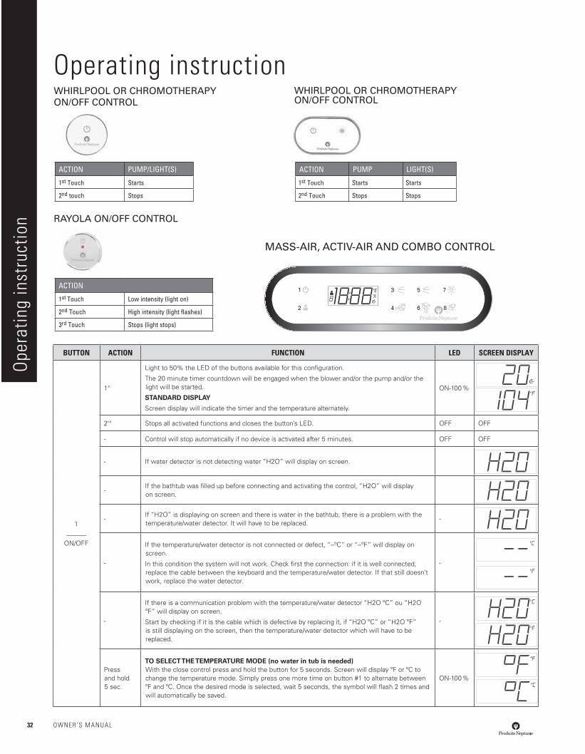
MASS-AIR, ACTIV-AIR AND COMBO CONTROL
WHIRLPOOL OR CHROMOTHERAPYON/OFF CONTROL
RAYOLA ON/OFF CONTROL
WHIRLPOOL OR CHROMOTHERAPYON/OFF CONTROL
BUTTON ACTION FUNCTION LED SCREEN DISPLAY
1______
ON/OFF
1st
Light to 50% the LED of the buttons available for this confi guration.
The 20 minute timer countdown will be engaged when the blower and/or the pump and/or the light will be started.
STANDARD DISPLAY
Screen display will indicate the timer and the temperature alternately.
ON-100 %
2nd Stops all activated functions and closes the button’s LED. OFF OFF
- Control will stop automatically if no device is activated after 5 minutes. OFF OFF
- If water detector is not detecting water “H2O” will display on screen.
-If the bathtub was fi lled up before connecting and activating the control, “H2O” will display on screen.
-If “H2O” is displaying on screen and there is water in the bathtub, there is a problem with the temperature/water detector. It will have to be replaced.
-
-
If the temperature/water detector is not connected or defect, “--ºC” or “--ºF” will display on screen.
In this condition the system will not work. Check fi rst the connection: if it is well connected, replace the cable between the keyboard and the temperature/water detector. If that still doesn’t work, replace the water detector.
-
-
If there is a communication problem with the temperature/water detector “H2O ºC” ou “H2O ºF” will display on screen.
Start by checking if it is the cable which is defective by replacing it, if “H2O ºC” or “H2O ºF” is still displaying on the screen, then the temperature/water detector which will have to be replaced.
-
Press and hold5 sec.
TO SELECT THE TEMPERATURE MODE (no water in tub is needed) With the close control press and hold the button for 5 seconds. Screen will display ºF or ºC to change the temperature mode. Simply press one more time on button #1 to alternate between ºF and ºC. Once the desired mode is selected, wait 5 seconds, the symbol will fl ash 2 times and will automatically be saved.
ON-100 %
ACTION PUMP LIGHT(S)
1st Touch Starts Starts
2nd Touch Stops Stops
ACTION PUMP/LIGHT(S)
1st Touch Starts
2nd touch Stops
ACTION
1st Touch Low intensity (light on)
2nd Touch High intensity (light fl ashes)
3rd Touch Stops (light stops)
Oper
atin
g in
stru
ctio
n
32 OWNER’S MANUAL
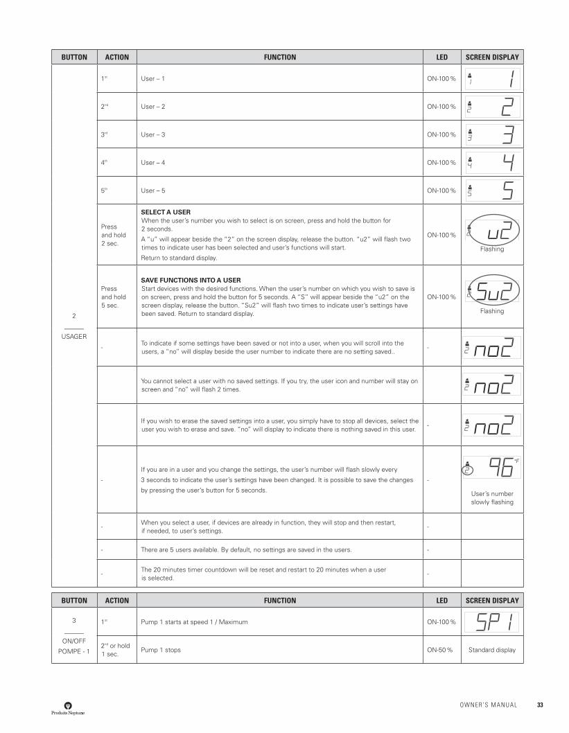
BUTTON ACTION FUNCTION LED SCREEN DISPLAY
2
______
USAGER
1st User – 1 ON-100 %
2nd User – 2 ON-100 %
3rd User – 3 ON-100 %
4th User – 4 ON-100 %
5th User – 5 ON-100 %
Press and hold 2 sec.
SELECT A USERWhen the user’s number you wish to select is on screen, press and hold the button for 2 seconds.
A “u” will appear beside the “2” on the screen display, release the button. “u2” will fl ash two times to indicate user has been selected and user’s functions will start.
Return to standard display.
ON-100 %
Flashing
Press and hold 5 sec.
SAVE FUNCTIONS INTO A USERStart devices with the desired functions. When the user’s number on which you wish to save is on screen, press and hold the button for 5 seconds. A “S” will appear beside the “u2” on the screen display, release the button. “Su2” will fl ash two times to indicate user’s settings have been saved. Return to standard display.
ON-100 %
Flashing
-To indicate if some settings have been saved or not into a user, when you will scroll into the users, a “no” will display beside the user number to indicate there are no setting saved..
-
You cannot select a user with no saved settings. If you try, the user icon and number will stay on screen and “no” will fl ash 2 times.
If you wish to erase the saved settings into a user, you simply have to stop all devices, select the user you wish to erase and save. “no” will display to indicate there is nothing saved in this user.
-
-
If you are in a user and you change the settings, the user’s number will fl ash slowly every
3 seconds to indicate the user’s settings have been changed. It is possible to save the changes
by pressing the user’s button for 5 seconds.
-
User’s number slowly fl ashing
-When you select a user, if devices are already in function, they will stop and then restart, if needed, to user’s settings.
-
- There are 5 users available. By default, no settings are saved in the users. -
-The 20 minutes timer countdown will be reset and restart to 20 minutes when a user is selected.
-
BUTTON ACTION FUNCTION LED SCREEN DISPLAY
3
______
ON/OFF
POMPE - 1
1st Pump 1 starts at speed 1 / Maximum ON-100 %
2nd or hold 1 sec.
Pump 1 stops ON-50 % Standard display
OWNER’S MANUAL 33
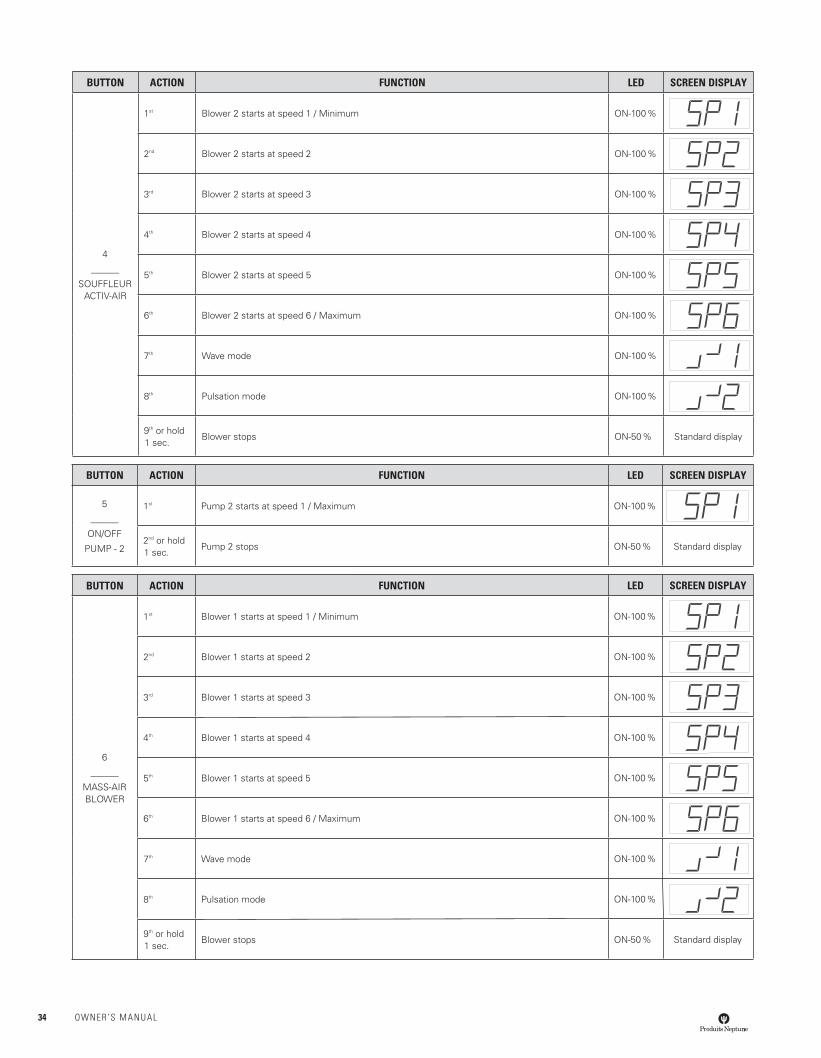
BUTTON ACTION FUNCTION LED SCREEN DISPLAY
4
______
SOUFFLEURACTIV-AIR
1st Blower 2 starts at speed 1 / Minimum ON-100 %
2nd Blower 2 starts at speed 2 ON-100 %
3rd Blower 2 starts at speed 3 ON-100 %
4th Blower 2 starts at speed 4 ON-100 %
5th Blower 2 starts at speed 5 ON-100 %
6th Blower 2 starts at speed 6 / Maximum ON-100 %
7th Wave mode ON-100 %
8th Pulsation mode ON-100 %
9th or hold 1 sec.
Blower stops ON-50 % Standard display
BUTTON ACTION FUNCTION LED SCREEN DISPLAY
5
______
ON/OFF
PUMP - 2
1st Pump 2 starts at speed 1 / Maximum ON-100 %
2nd or hold 1 sec.
Pump 2 stops ON-50 % Standard display
BUTTON ACTION FUNCTION LED SCREEN DISPLAY
6
______
MASS-AIRBLOWER
1st Blower 1 starts at speed 1 / Minimum ON-100 %
2nd Blower 1 starts at speed 2 ON-100 %
3rd Blower 1 starts at speed 3 ON-100 %
4th Blower 1 starts at speed 4 ON-100 %
5th Blower 1 starts at speed 5 ON-100 %
6th Blower 1 starts at speed 6 / Maximum ON-100 %
7th Wave mode ON-100 %
8th Pulsation mode ON-100 %
9th or hold 1 sec.
Blower stops ON-50 % Standard display
34 OWNER’S MANUAL
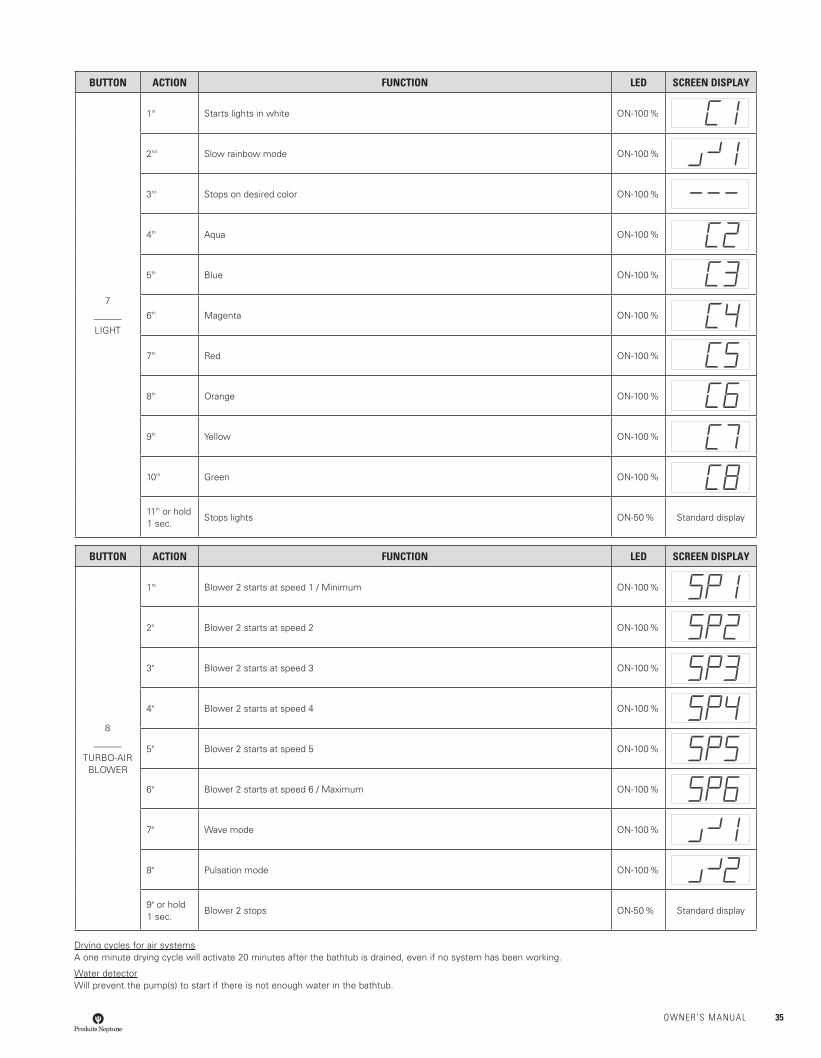
BUTTON ACTION FUNCTION LED SCREEN DISPLAY
7
______
LIGHT
1st Starts lights in white ON-100 %
2nd Slow rainbow mode ON-100 %
3rd Stops on desired color ON-100 %
4th Aqua ON-100 %
5th Blue ON-100 %
6th Magenta ON-100 %
7th Red ON-100 %
8th Orange ON-100 %
9th Yellow ON-100 %
10th Green ON-100 %
11th or hold 1 sec.
Stops lights ON-50 % Standard display
BUTTON ACTION FUNCTION LED SCREEN DISPLAY
8
______
TURBO-AIRBLOWER
1re Blower 2 starts at speed 1 / Minimum ON-100 %
2e Blower 2 starts at speed 2 ON-100 %
3e Blower 2 starts at speed 3 ON-100 %
4e Blower 2 starts at speed 4 ON-100 %
5e Blower 2 starts at speed 5 ON-100 %
6e Blower 2 starts at speed 6 / Maximum ON-100 %
7e Wave mode ON-100 %
8e Pulsation mode ON-100 %
9e or hold 1 sec.
Blower 2 stops ON-50 % Standard display
Drying cycles for air systemsA one minute drying cycle will activate 20 minutes after the bathtub is drained, even if no system has been working.
Water detectorWill prevent the pump(s) to start if there is not enough water in the bathtub.
OWNER’S MANUAL 35
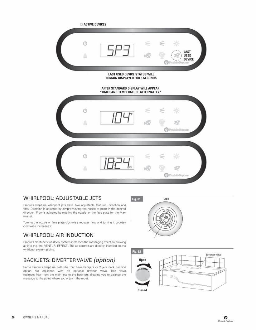
WHIRLPOOL: ADJUSTABLE JETSProduits Neptune whirlpool jets have two adjustable features, direction and fl ow. Direction is adjusted by simply moving the nozzle to point in the desired direction. Flow is adjusted by rotating the nozzle or the face plate for the Max-ima jet.
Turning the nozzle or face plate clockwise reduces fl ow and turning it counter-clockwise increases it.
WHIRLPOOL: AIR INDUCTIONProduits Neptune’s whirlpool system increases the massaging effect by drawing air into the jets (VENTURI EFFECT). The air controls are directly installed on the whirlpool system piping.
BACKJETS: DIVERTER VALVE (option)Some Produits Neptune bathtubs that have backjets or 2 jets neck cushion option are equipped with an optional diverter valve. This valve redirects fl ow from the main jets to the back-jets allowing you to balance the massage to the point where you enjoy it the most.
ACTIVE DEVICES
LASTUSEDDEVICE
LAST USED DEVICE STATUS WILLREMAIN DISPLAYED FOR 5 SECONDS
AFTER STANDARD DISPLAY WILL APPEAR*TIMER AND TEMPERATURE ALTERNATELY*
Fig. 81
Fig. 82
Open
Closed
36 OWNER’S MANUAL
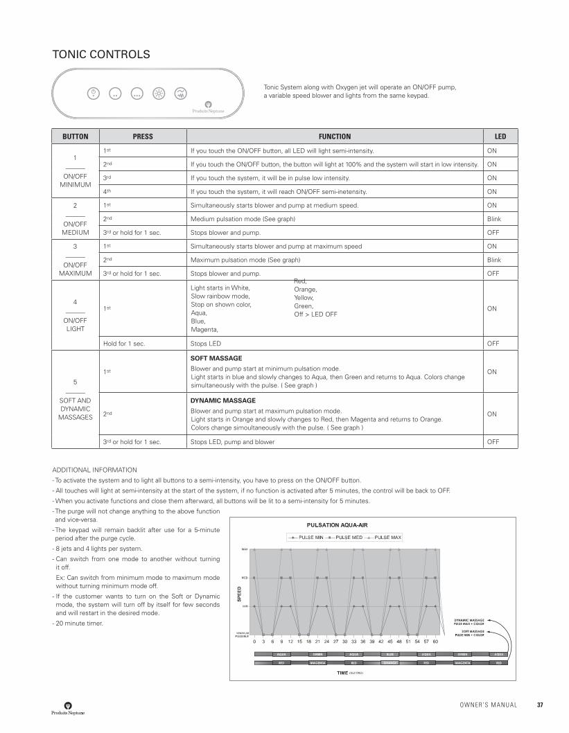
BUTTON PRESS FUNCTION LED
1______
ON/OFFMINIMUM
1st If you touch the ON/OFF button, all LED will light semi-intensity. ON
2nd If you touch the ON/OFF button, the button will light at 100% and the system will start in low intensity. ON
3rd If you touch the system, it will be in pulse low intensity. ON
4th If you touch the system, it will reach ON/OFF semi-inetensity. ON
2______
ON/OFFMEDIUM
1st Simultaneously starts blower and pump at medium speed. ON
2nd Medium pulsation mode (See graph) Blink
3rd or hold for 1 sec. Stops blower and pump. OFF
3______
ON/OFFMAXIMUM
1st Simultaneously starts blower and pump at maximum speed ON
2nd Maximum pulsation mode (See graph) Blink
3rd or hold for 1 sec. Stops blower and pump. OFF
4______
ON/OFFLIGHT
1st
Light starts in White,Slow rainbow mode,Stop on shown color,Aqua,Blue,Magenta,
ON
Hold for 1 sec. Stops LED OFF
5______
SOFT AND DYNAMIC
MASSAGES
1st
SOFT MASSAGE
Blower and pump start at minimum pulsation mode.Light starts in blue and slowly changes to Aqua, then Green and returns to Aqua. Colors change simultaneously with the pulse. ( See graph )
ON
2nd
DYNAMIC MASSAGE
Blower and pump start at maximum pulsation mode.Light starts in Orange and slowly changes to Red, then Magenta and returns to Orange. Colors change simoultaneously with the pulse. ( See graph )
ON
3rd or hold for 1 sec. Stops LED, pump and blower OFF
ADDITIONAL INFORMATION
- To activate the system and to light all buttons to a semi-intensity, you have to press on the ON/OFF button.
- All touches will light at semi-intensity at the start of the system, if no function is activated after 5 minutes, the control will be back to OFF.
- When you activate functions and close them afterward, all buttons will be lit to a semi-intensity for 5 minutes.
- The purge will not change anything to the above function and vice-versa.
- The keypad will remain backlit after use for a 5-minute period after the purge cycle.
- 8 jets and 4 lights per system.
- Can switch from one mode to another without turning it off.
Ex: Can switch from minimum mode to maximum mode without turning minimum mode off.
- If the customer wants to turn on the Soft or Dynamic mode, the system will turn off by itself for few seconds and will restart in the desired mode.
- 20 minute timer.
TONIC CONTROLS
Tonic System along with Oxygen jet will operate an ON/OFF pump, a variable speed blower and lights from the same keypad.
Red,Orange,Yellow,Green,Off > LED OFF
OWNER’S MANUAL 37
SHOWER AND SHOWER BASEINSTALLATIONPlease read carefully all of the installation and maintenance instructions con-tained in this guide. We strongly recommend the installation is done by a quali-fi ed and authorized specialist, in accordance with building codes and laws.
This quality product was thoroughly inspected in factory against any manufac-turing defect before being packed. However, if this product is defective, do not proceed to the installation and inform your retailer immediately.
The installation of a defective product or a bad installation cancels the manu-facturer’s guarantee. To honor your guarantee, you must keep your purchase invoice or provide us a proof of purchase by referring to your retailer. The Produits Neptune guarantee (for life on any manufacturing defect of all the acrylic products) is nontransferable.
BEFORE BEGINNING
Before installing your new PRODUITS NEPTUNE shower, we strongly recom-mend you to follow these few simple steps.
• Prior to removing your old shower, carefully inspect the new one for damage. Do not install a damaged unit. Please contact your local representa-tive for assistance.
• Ensure that the shower you have is the one you ordered and that the dimen-sions are exact.
• Ensure plumbing rough-in for both the drain and the supply lines are com-pleted according to your shower or shower base’s dimensions.
• The fl oor area where your shower will be installed must be structurally sound and strong enough to hold the shower and an adult’s weight. Also make sure that the walls and fl oor are square, plumb and level. If need be, level the fl oor with fl oor leveler.
• It is essential to have an access panel for plumbing maintenance. The building code generally requires the installation of an access panel of a minimum of 30 X 50 cm to facilitate plumbing maintenance.
NECESSARY TOOLS
NECESSARY MATERIALS
• Silicone sealant (mildew resistant)
• Construction glue
• Shims (cedar shingles)
• Standard or self-drilling screws
• Mortar (optional)
PREPARATION OF THE SITE
• Sweep the fl oor to remove construction debris and vacuum to remove all remaining dust.
• If renovating, remove all existing wall material in order to install shower directly on wall studs.
• Ensure that the wood frame has the appropriate dimensions.
• If you plan on installing a door, you will also need to plan studs to receive the fastener screws when installing the jambs. Please refer to the installation guide provided with the door.
• All plumbing rough-in for both the drain and the supply should be completed before installing the shower.
• Check the distance between the wall, the shower and the studs to ensure that your valves and fi ttings fi t well.
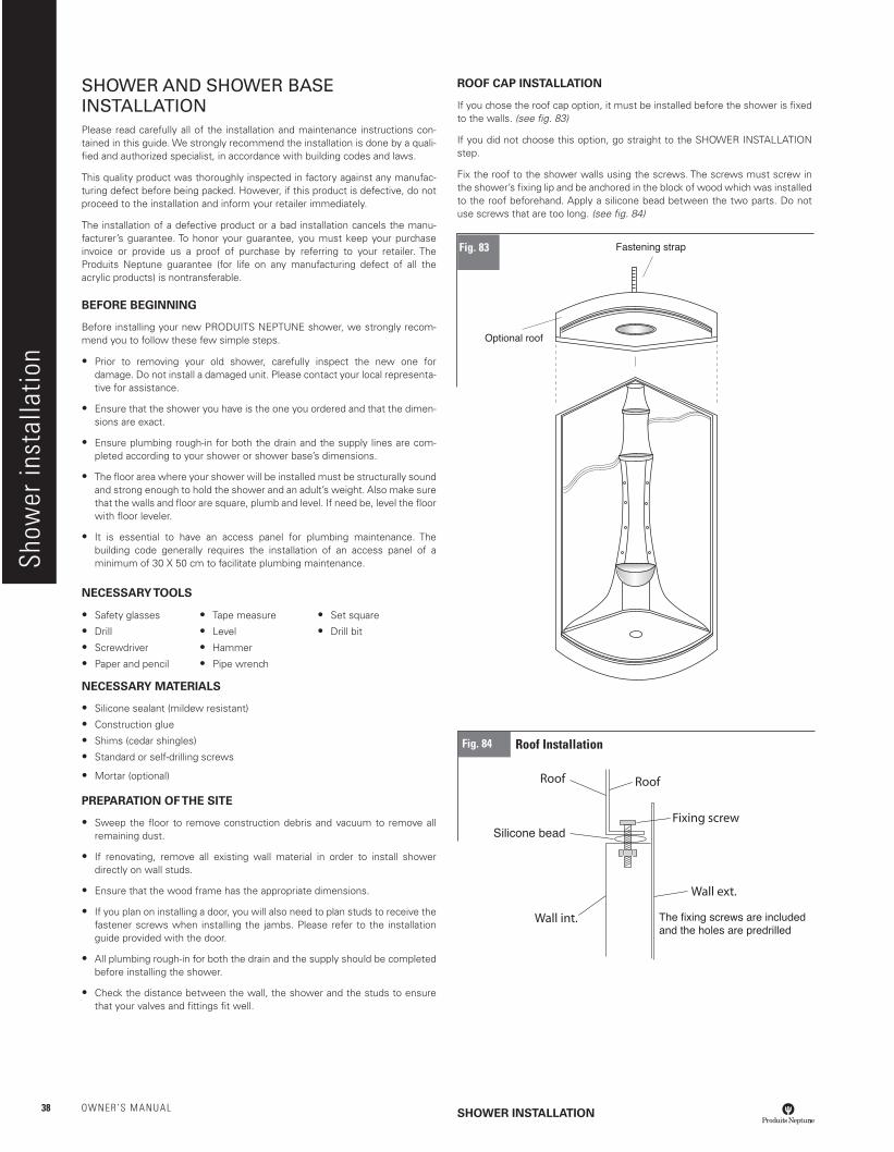
ROOF CAP INSTALLATION
If you chose the roof cap option, it must be installed before the shower is fi xed to the walls. (see fi g. 83)
If you did not choose this option, go straight to the SHOWER INSTALLATION step.
Fix the roof to the shower walls using the screws. The screws must screw in the shower’s fi xing lip and be anchored in the block of wood which was installed to the roof beforehand. Apply a silicone bead between the two parts. Do not use screws that are too long. (see fi g. 84)
SHOWER INSTALLATION
• Safety glasses
• Drill
• Screwdriver
• Paper and pencil
• Tape measure
• Level
• Hammer
• Pipe wrench
• Set square
• Drill bit
Show
er in
stal
latio
n
Fig. 83
Fig. 84 Roof Installation
38 OWNER’S MANUAL
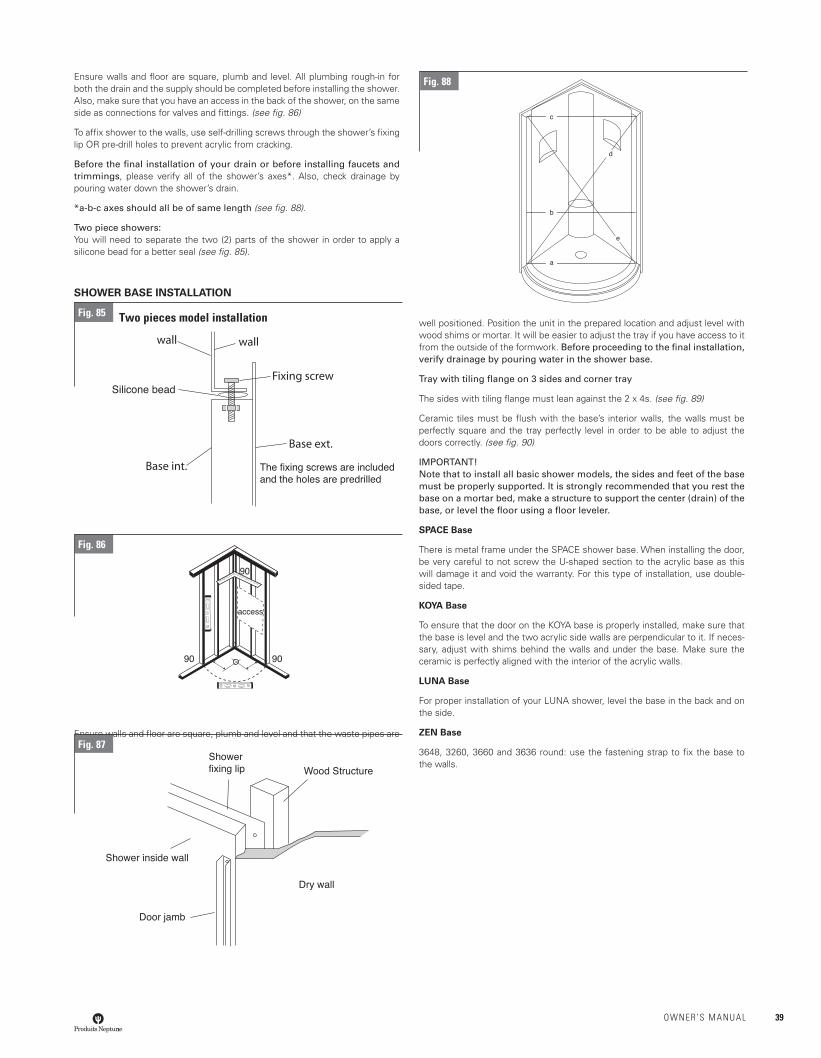
Ensure walls and fl oor are square, plumb and level. All plumbing rough-in for both the drain and the supply should be completed before installing the shower. Also, make sure that you have an access in the back of the shower, on the same side as connections for valves and fi ttings. (see fi g. 86)
To affi x shower to the walls, use self-drilling screws through the shower’s fi xing lip OR pre-drill holes to prevent acrylic from cracking.
Before the fi nal installation of your drain or before installing faucets and trimmings, please verify all of the shower’s axes*. Also, check drainage by pouring water down the shower’s drain.
*a-b-c axes should all be of same length (see fi g. 88).
Two piece showers: You will need to separate the two (2) parts of the shower in order to apply a silicone bead for a better seal (see fi g. 85).
SHOWER BASE INSTALLATION
Ensure walls and fl oor are square, plumb and level and that the waste pipes are
well positioned. Position the unit in the prepared location and adjust level with wood shims or mortar. It will be easier to adjust the tray if you have access to it from the outside of the formwork. Before proceeding to the fi nal installation, verify drainage by pouring water in the shower base.
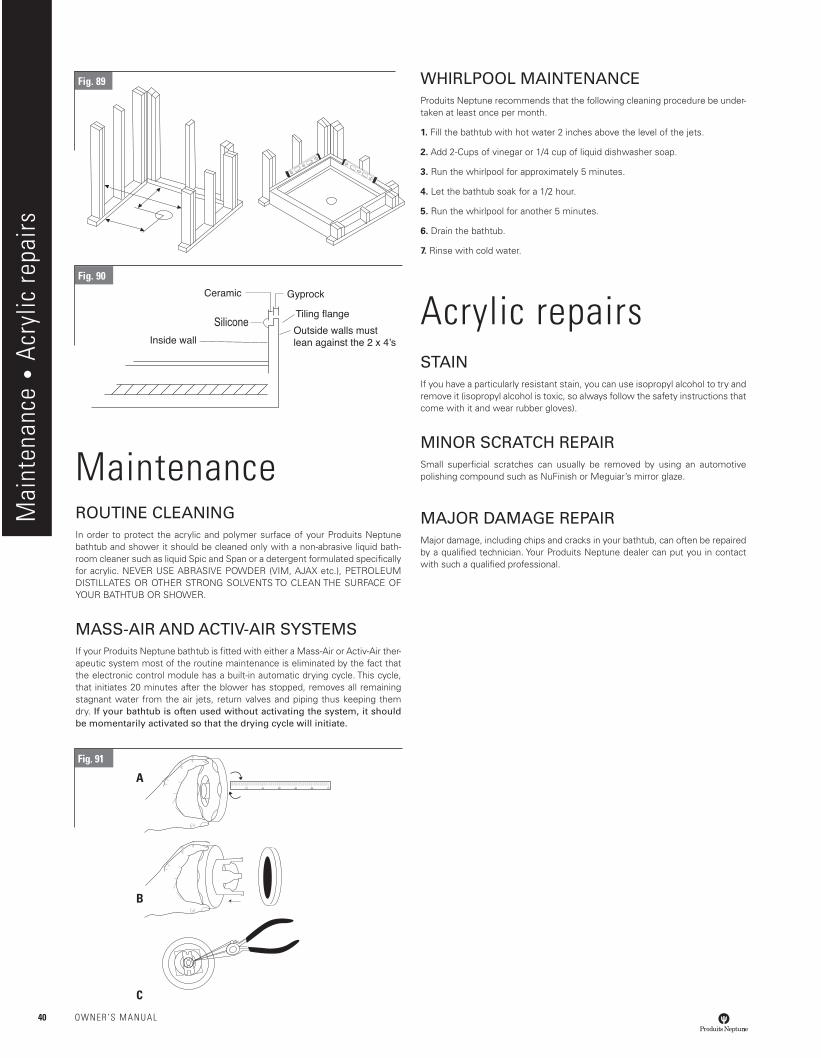
Tray with tiling fl ange on 3 sides and corner tray
The sides with tiling fl ange must lean against the 2 x 4s. (see fi g. 89)
Ceramic tiles must be fl ush with the base’s interior walls, the walls must be perfectly square and the tray perfectly level in order to be able to adjust the doors correctly. (see fi g. 90)
IMPORTANT! Note that to install all basic shower models, the sides and feet of the base must be properly supported. It is strongly recommended that you rest the base on a mortar bed, make a structure to support the center (drain) of the base, or level the fl oor using a fl oor leveler.
SPACE Base
There is metal frame under the SPACE shower base. When installing the door, be very careful to not screw the U-shaped section to the acrylic base as this will damage it and void the warranty. For this type of installation, use double-sided tape.
KOYA Base
To ensure that the door on the KOYA base is properly installed, make sure that the base is level and the two acrylic side walls are perpendicular to it. If neces-sary, adjust with shims behind the walls and under the base. Make sure the ceramic is perfectly aligned with the interior of the acrylic walls.
LUNA Base
For proper installation of your LUNA shower, level the base in the back and on the side.
ZEN Base
3648, 3260, 3660 and 3636 round: use the fastening strap to fi x the base to the walls.
Fig. 88
Fig. 85 Two pieces model installation
Fig. 86
Fig. 87
OWNER’S MANUAL 39
MaintenanceROUTINE CLEANINGIn order to protect the acrylic and polymer surface of your Produits Neptune bathtub and shower it should be cleaned only with a non-abrasive liquid bath-room cleaner such as liquid Spic and Span or a detergent formulated specifi cally for acrylic. NEVER USE ABRASIVE POWDER (VIM, AJAX etc.), PETROLEUM DISTILLATES OR OTHER STRONG SOLVENTS TO CLEAN THE SURFACE OF YOUR BATHTUB OR SHOWER.
MASS-AIR AND ACTIV-AIR SYSTEMSIf your Produits Neptune bathtub is fi tted with either a Mass-Air or Activ-Air ther-apeutic system most of the routine maintenance is eliminated by the fact that the electronic control module has a built-in automatic drying cycle. This cycle, that initiates 20 minutes after the blower has stopped, removes all remaining stagnant water from the air jets, return valves and piping thus keeping them dry. If your bathtub is often used without activating the system, it should be momentarily activated so that the drying cycle will initiate.
WHIRLPOOL MAINTENANCEProduits Neptune recommends that the following cleaning procedure be under-taken at least once per month.
1. Fill the bathtub with hot water 2 inches above the level of the jets.
2. Add 2-Cups of vinegar or 1/4 cup of liquid dishwasher soap.
3. Run the whirlpool for approximately 5 minutes.
4. Let the bathtub soak for a 1/2 hour.
5. Run the whirlpool for another 5 minutes.
6. Drain the bathtub.
7. Rinse with cold water.
Acrylic repairsSTAINIf you have a particularly resistant stain, you can use isopropyl alcohol to try and remove it (isopropyl alcohol is toxic, so always follow the safety instructions that come with it and wear rubber gloves).
MINOR SCRATCH REPAIRSmall superfi cial scratches can usually be removed by using an automotive polishing compound such as NuFinish or Meguiar’s mirror glaze.
MAJOR DAMAGE REPAIRMajor damage, including chips and cracks in your bathtub, can often be repaired by a qualifi ed technician. Your Produits Neptune dealer can put you in contact with such a qualifi ed professional.
Fig. 91
A
B
C
Fig. 89
Mai
nten
ance
• A
cryl
ic re
pairs
Silicone
Fig. 90
40 OWNER’S MANUAL

Troubleshooting
IMPORTANT INFORMATION TO SAFEGUARD
Note : Always keep your original bill of sale
Date of purchase : Name of retailer:
Description of bathtub :
Serial # (indicated underneath the bathtub) :
PROBLEM SOLUTION
Water remains around the bathtub rim or drain.
Check that the installation is level and that the bathtub is sitting fi rmly on its feet. (Drain slope is built into the bathtub.) Shim with adjustment wedges if necessary.
Bathtub or shower bottom moves during use.
The bathtub is not sitting fi rmly on its feet. Shim with adjustment wedges or use the alternate mortar bed installation technique.
Bathtub moves relative to the walls during use.
The bathtub is not fi rmly supported under the rim. Check that 1”X2” supports contact the underside of the rim. Modify if necessary.
Protective plastic fi lm will not come off.
Use isopropyl alcohol.
Electronic control fails to operate. • Check the electrical power supply. Reset circuit or replace fuse if necessary.
• Check Ground Fault Circuit Interrupter (GFCI). Reset if tripped.
• If the system has been in operation for a long time it is possible that the thermal protection switch has shut off the motor. Turn off the system and wait 30 minutes for it to cool, then try again.
• Check the connections between the electronic control pad and the control module or pump.
Motor will not stop/ only some functions on the electronic control pad are working.
• Shut off power to the bathtub at the breaker. Make certain that no water has infi ltrated the control pad. Try drying the pad with a hair dryer.
• Check for excessive humidity under your bathtub and around the control pad and control module. Allow it to dry out and provide for adequate ventilation if necessary.
Excessive noise from blower or pump.
• Most of the noise from your Whirlpool, Mass-Air or Activ-Air system actually comes from the movement of the water.
• Check that the blower is fi rmly secured.
• Check that the pump is fi rmly in contact with the fl oor. Use adjustment shims and construction adhesive to secure if necessary.
• Make certain that there are no obstructions close to the intake of the blower, and that it has an adequate supply of fresh air.
• The bathtub can be insulated using bats of fi berglass around the tub. Make certain that you leave a 2 sq feet space around the pump or blower.
Blower runs but no air comes out through the jets.
Check that the main air hose from the blower to the manifold is properly connected. Reconnect and tighten clamps if necessary.
Air outlets in jet heads are blocked. • If the air outlets of a jet head are obstructed with soap or other residues, fi ll the tub with water and brush them gently with a toothbrush. Turn the system ON then OFF several times.
• Remove caps (Mass-Air & Activ-Air) and ball bearing and clean with cotton swabs. Use a rubber head hammer for reinstallation.
• If the problem persists tap the jet heads with a spoon while the blower is running (Mass-Air system only).
The air heater seems not to be functioning.
Note: The air heater is not designed to heat your bathwater, only to heat the incoming air to body temperature.
• To verify operation of the air heater, fi ll the bathtub to working level. Turn on the blower and let it run for approximately 5 minutes. Carefully feel the fl exible connection hose where it connects to the blower. The hose should feel warm to the touch. If not, contact your local distributor.
• If your bathtub is installed against exterior walls, make certain that they are properly insulated to minimize heat loss. The air entering the blower should be at least 20° C.
• Check that the blower is not drawing cold air from the basement or the space between the fl oors via the hole for the drain plumbing. Block the hole using either foam or fi berglass insulation.
• People with sensitive skin might experience a “cold air effect” caused by the sensation of the air bubbles running along the wet skin and giving the bather a shivering sensation. Simply move the body slightly away from the closest jet.
the incoming air to body tempera-ture.The air coming from the jets seem cold
Temperature difference
• There will be a temperature difference between the air coming from the jets and the water temperature. The air tem-perature will be a little over the room temperature (22 to 25 degrees Celsius – 71 to 77 degrees Fahrenheit), depending on the number of jets in the bathtub. The water on the other hand, will be warmer (about 34 to 40 degrees Celsius – 93 to 104 degrees Fahrenheit).
• The air is not cold: it is just not as warm as the bathtub water. If it weren’t for the heating element that’s in the blower, the temperature difference would be a lot greater.
“H2O” code displayed on the screen
• Make sure everything is connected, and that the ON/OFF control has been activated before fi lling up the bathtub.• Fill the tub about 3” above the water jet in order to have the water sensor work properly.
OWNER’S MANUAL 41
Trou
bles
hoot
ing
War
rant
y
September 2014
PRODUITS NEPTUNE QUALITYThis logo certifi es that your product has been inspected and tested by our specialists and that it is compliant with our high Produits Neptune quality standards.
CSA LISTED/WARNOCK-HERSEYOur products and their components have received CSA or Warnock-Hersey certifi cation, which attests to their quality and reliability.
UPCIAPMO: Our Amaze, faucets and porcelain products have received UPC certifi cation.
WATERSENSEOur toilets have received WaterSense certifi cation.
CERTIFICATION ECORESPONSIBLEOur products have been certifi ed ECORESPONSIBLE, recognizing Produits Neptune’s initiatives towards limiting its environmental footprint.
WARRANTYEach Produits Neptune product has been subjected to rigorous quality controls and we guarantee that it conforms to the highest quality standards. In order to ensure a trouble-free installation, we strong ly recommend that you read the installation manual and our warranty terms joined with the product carefully before beginning any work. Our warranty covers parts and labor for repairs only and does not cover additional costs related to defective product replacement.
BATHTUBS & SHOWERS
ACRYLIC SHELL: Limited lifetime warranty against manufacturing defects.
AMAZE ACRYLIC SHELL: Limited 4-year warranty against manufacturing defects (parts and labor).
POLYMER SHELL: 5 year warranty against manufac-turing defects.
SYSTEMS: Limited 10-year warranty (parts and labor) against manufacturing defects; jets, pipes, fi ttings, electronic control pads, pumps, inline heaters, blowers, black box, remote controls, ozonator, wiring, etc. and leaks related to manufacturing defects.
Limited 5-year warranty against manufacturing defects related to colored jet trims inside the bathtub.
OPTIONS
WOOD TRIM: Limited 1-year warranty against manufacturing defects.
GENERAL: Chromotherapy, neck pillows, handles and other options. Limited 5-year warranty against manufacturing defects for all parts.
DOORS Limited 10-year warranty against manufacturing defects, covers parts other than gaskets, magnets &
installation hardware which have a 1-year warranty against manufacturing defects.
TOILETS
PORCELAIN: Limited 5-year warranty against manufacturing defects.
PARTS:Limited 5-year warranty against manufacturing defects for parts inside tank; Limited 1-year warranty for installation hardware.
SEATS: Limited 1-year warranty against manufacturing defects.
SINKS Limited 1-year warranty against manufacturing defects.
FAUCETS AND DRAINS Limited lifetime warranty against manufacturing defects on all parts including cartridges.
FAUCETS:Limited lifetime warranty on Chrome fi nish.
SHOWER TOWER:Limited 3-year warranty on Chrome fi nish and hand shower limited 1-year warranty on Chrome fi nish.
DRAINS:Limited lifetime warranty for Chrome and Brushed Nickel fi nishes.
AMAZE DRAIN: Limited 4-year warranty on fi nish (parts).
FANS Limited 3-year warranty against manufacturing defects, including heat lamps.
IMPORTANT!
• If a showroom product is sold, the warranty period begins on the date of purchase from Produits Neptune by the retailer.
• For commercial use, all products have a one-year warranty against manufacturing defects.
• The Produits Neptune warranty is solely for the personal household use of the original owner/user and starts on the date of purchase from Produits Neptune by the retailer. The warranty will take effect when the original owner/user presents the original bill of sale or the model serial number.
The warranty is not transferable to subsequent owners.
All products replaced or repaired during the war-ranty period will still be covered for the remainder of the original warranty.
WARRANTIES AND CERTIFICATIONS
42 OWNER’S MANUAL