Products | Solutions | Service Boxes/Worm_Gear_Boxes.pdf · Worm Gear Boxes Chapter 7 6...
60
Worm Gear Boxes Chapter 7 Products | Solutions | Service Chapter 7 Products | Solutions | Service Worm Gear Boxes Worm Gear Boxes Chapter 7 Products | Solutions | Service
Transcript of Products | Solutions | Service Boxes/Worm_Gear_Boxes.pdf · Worm Gear Boxes Chapter 7 6...
Worm Gear Boxes Chapter 7
Products | Solutions | Service
Chapter 7
Products | Solutions | Service
Worm Gear BoxesWorm Gear Boxes Chapter 7
Products | Solutions | Service

We hereby reserve the right to change content of data in this catalogue at any time without notice.Our company shall not be held responsible for neither possible discrepancies in catalogue content nor any damage caused by wrong use of products or information. Lönne Scandinavia AS reserves the prohibition to publish pages or whole parts of this catalogue without authorization. All product names occurring or referred to in this catalogue are or may be registered trademarks belonging to their respective producers or trademark owners.The dimensions are in mm.Illustrations are not binding.
Worm Gear Boxes Chapter 7
3
Index
General Product Overview 5Single Worm Gear Boxes 030 - 110 12Single Worm Gear Boxes with Spur Gear P45 - P10 26Combined Worm Gear Unit 303 - 115 38Product News, Square Worm Gear Boxes 56Product News High Tech Worm Gear Boxes 57Product News Stainlessteel Worm and Coaxial Gear Boxes 58Appendix 59
Page
Index
Chapter 7Worm Gear Boxes
3
General Product Overview 5Single Worm Gear Boxes 030 - 110 12Single Worm Gear Boxes with Spur Gear P45 - P10 26Combined Worm Gear Unit 303 - 115 38Product News, Square Worm Gear Boxes 56Product News High Tech Worm Gear Boxes 57Product News Stainlessteel Worm and Coaxial Gear Boxes 58
59
Page
Worm Gear Boxes Chapter 7
3
Important addresses and phone numbers. General info.

Worm Gear Boxes Chapter 7
5
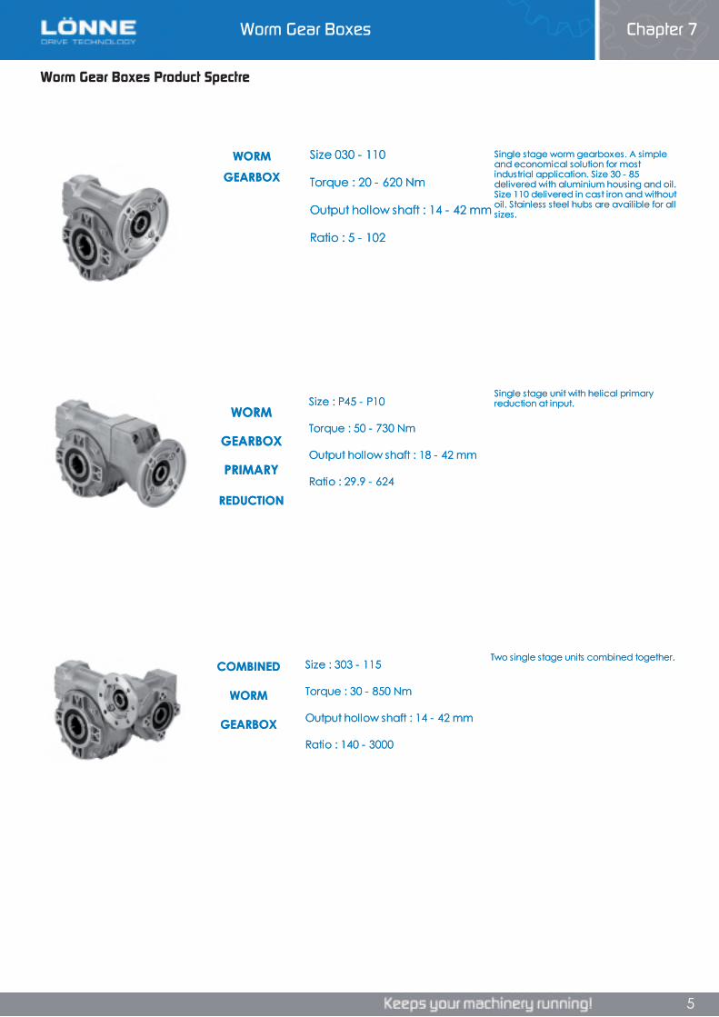
Worm Gear Boxes Product Spectre
Single stage worm gearboxes. A simple and economical solution for most industrial application. Size 30 - 85 delivered with aluminium housing and oil. Size 110 delivered in cast iron and without oil. Stainless steel hubs are availible for all sizes.
COMBINED WORM GEARBOX
Size : 303 - 115
Torque : 30 - 850 Nm
Output hollow shaft : 14 - 42 mm
Ratio : 140 - 3000
Two single stage units combined together.
WORM GEARBOX
Size 030 - 110
Torque : 20 - 620 Nm
Output hollow shaft : 14 - 42 mm
Ratio : 5 - 102
WORM
GEARBOX
PRIMARY
REDUCTION
Size : P45 - P10
Torque : 50 - 730 Nm
Output hollow shaft : 18 - 42 mm
Ratio : 29.9 - 624
Single stage unit with helical primary reduction at input.
Worm Gear Boxes Product SpectreWorm Gear Boxes Product Spectre
Single stage worm gearboxes. A simple and economical solution for most industrial application. Size 30 - 85 delivered with aluminium housing and oil. Size 110 delivered in cast iron and without oil. Stainless steel hubs are availible for all sizes.
COMBINED WORM GEARBOX
Size : 303 - 115
Torque : 30 - 850 Nm
Output hollow shaft : 14 - 42 mm
Ratio : 140 - 3000
Two single stage units combined together.
WORM GEARBOX
Size 030 - 110
Torque : 20 - 620 Nm
Output hollow shaft : 14 - 42 mm
Ratio : 5 - 102
WORM
GEARBOX
PRIMARY
REDUCTION
Size : P45 - P10
Torque : 50 - 730 Nm
Output hollow shaft : 18 - 42 mm
Ratio : 29.9 - 624
Single stage unit with helical primary reduction at input.
Chapter 7Worm Gear Boxes
5
Single stage worm gearboxes. A simple and economical solution for most industrial application. Size 30 - 85 delivered with aluminium housing and oil. Size 110 delivered in cast iron and without oil. Stainless steel hubs are availible for all sizes.
COMBINED WORM GEARBOX
Size : 303 - 115
Torque : 30 - 850 Nm
Output hollow shaft : 14 - 42 mm
Ratio : 140 - 3000
Two single stage units combined together.
WORM GEARBOX
Size 030 - 110
Torque : 20 - 620 Nm
Output hollow shaft : 14 - 42 mm
Ratio : 5 - 102
WORM
GEARBOX
PRIMARY
REDUCTION
Size : P45 - P10
Torque : 50 - 730 Nm
Output hollow shaft : 18 - 42 mm
Ratio : 29.9 - 624
Single stage unit with helical primary reduction at input.
5
Worm Gear Boxes Chapter 7
Worm Gear Boxes Chapter 7
6
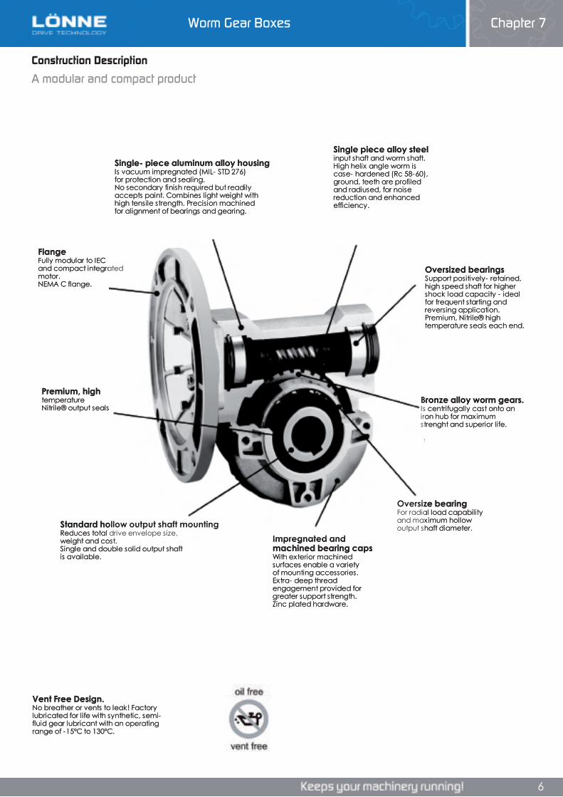
Construction Description
A modular and compact product
Single- piece aluminum alloy housing Is vacuum impregnated (MIL- STD 276) for protection and sealing. No secondary finish required but readily accepts paint. Combines light weight withhigh tensile strength. Precision machinedfor alignment of bearings and gearing.
Single piece alloy steel input shaft and worm shaft. High helix angle worm is case- hardened (Rc 58-60), ground, teeth are profiled and radiused, for noise reduction and enhanced efficiency.
FlangeFully modular to IEC and compact integrated motor.NEMA C flange.
Oversized bearings Support positively- retained, high speed shaft for higher shock load capacity - ideal for frequent starting and reversing application. Premium, Nitrile® high temperature seals each end.
Premium, high temperatureNitrile® output seals
Bronze alloy worm gears. Is centrifugally cast onto an iron hub for maximum strenght and superior life.
Oversize bearing For radial load capability and maximum hollow output shaft diameter.
Impregnated and machined bearing capsWith exterior machined surfaces enable a variety of mounting accessories. Extra- deep thread engagement provided for greater support strength. Zinc plated hardware.
Standard hollow output shaft mounting Reduces total drive envelope size, weight and cost. Single and double solid output shaft is available.
Vent Free Design. No breather or vents to leak! Factory lubricated for life with synthetic, semi-fluid gear lubricant with an operating range of -15ºC to 130ºC.
Construction Description
A modular and compact product
Chapter 7Worm Gear Boxes
Construction Description
A modular and compact product
Single- piece aluminum alloy housing Is vacuum impregnated (MIL- STD 276) for protection and sealing. No secondary finish required but readily accepts paint. Combines light weight withhigh tensile strength. Precision machinedfor alignment of bearings and gearing.
Single piece alloy steel input shaft and worm shaft. High helix angle worm is case- hardened (Rc 58-60), ground, teeth are profiled and radiused, for noise reduction and enhanced efficiency.
FlangeFully modular to IEC and compact integrated motor.NEMA C flange.
Oversized bearings Support positively- retained, high speed shaft for higher shock load capacity - ideal for frequent starting and reversing application. Premium, Nitrile® high temperature seals each end.
Premium, high temperatureNitrile® output seals
Bronze alloy worm gears. Is centrifugally cast onto an iron hub for maximum strenght and superior life.
Oversize bearing For radial load capability and maximum hollow output shaft diameter.
Impregnated and machined bearing capsWith exterior machined surfaces enable a variety of mounting accessories. Extra- deep thread engagement provided for greater support strength. Zinc plated hardware.
Standard hollow output shaft mounting Reduces total drive envelope size, weight and cost. Single and double solid output shaft is available.
Vent Free Design. No breather or vents to leak! Factory lubricated for life with synthetic, semi-fluid gear lubricant with an operating range of -15ºC to 130ºC.
6
Worm Gear Boxes Chapter 7
Worm Gear Boxes Chapter 7
7
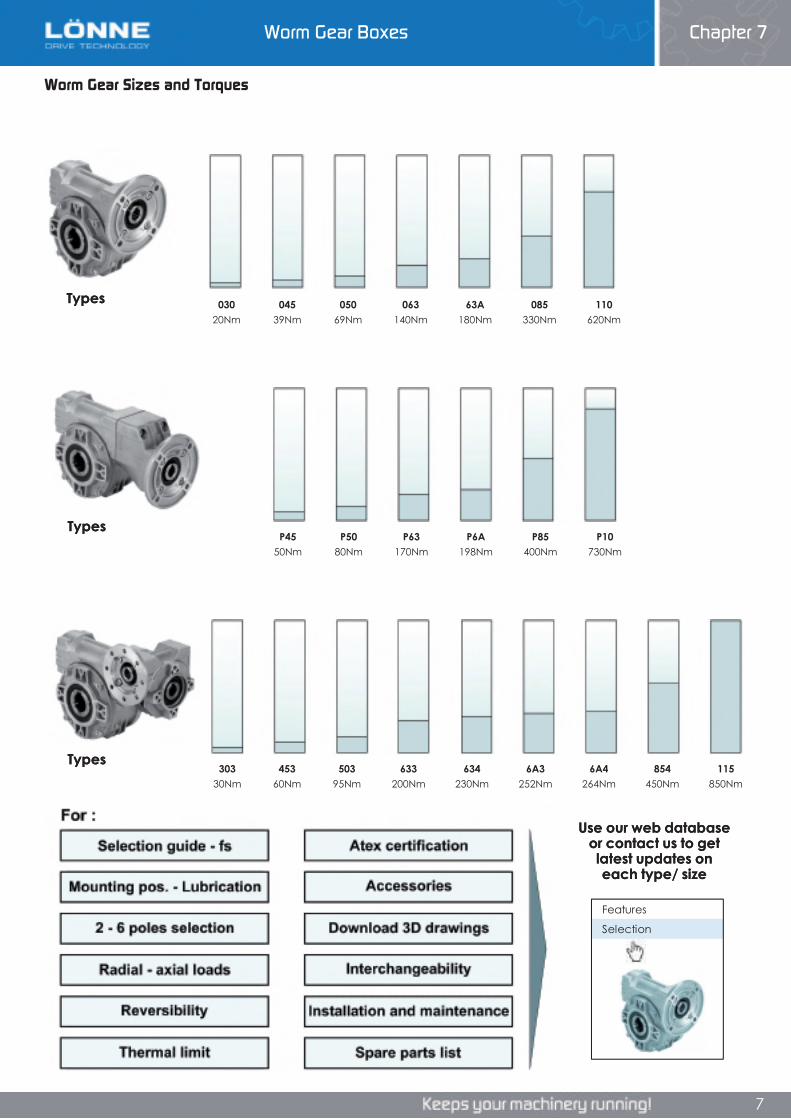
Worm Gear Sizes and Torques
Features
Selection
030 045 050 063 63A 085 11020Nm 39Nm 69Nm 140Nm 180Nm 330Nm 620Nm
303 453 503 633 634 6A3 6A4 854 11530Nm 60Nm 95Nm 200Nm 230Nm 252Nm 264Nm 450Nm 850Nm
P45 P50 P63 P6A P85 P1050Nm 80Nm 170Nm 198Nm 400Nm 730Nm
Types
Types
Types
Use our web databaseor contact us to get latest updates on each type/ size
Worm Gear Sizes and TorquesWorm Gear Sizes and Torques
Features
Selection
030 045 050 063 63A 085 11020Nm 39Nm 69Nm 140Nm 180Nm 330Nm 620Nm
303 453 503 633 634 6A3 6A4 854 11530Nm 60Nm 95Nm 200Nm 230Nm 252Nm 264Nm 450Nm 850Nm
P45 P50 P63 P6A P85 P1050Nm 80Nm 170Nm 198Nm 400Nm 730Nm
Types
Types
Types
Use our web databaseor contact us to get latest updates on each type/ size
Chapter 7Worm Gear Boxes
7
Features
Selection
030 045 050 063 63A 085 11020Nm 39Nm 69Nm 140Nm 180Nm 330Nm 620Nm
303 453 503 633 634 6A3 6A4 854 11530Nm 60Nm 95Nm 200Nm 230Nm 252Nm 264Nm 450Nm 850Nm
P45 P50 P63 P6A P85 P1050Nm 80Nm 170Nm 198Nm 400Nm 730Nm
Types
Types
Types
Use our web databaseor contact us to get latest updates on each type/ size
7
Worm Gear Boxes Chapter 7
Worm Gear Boxes Chapter 7
8
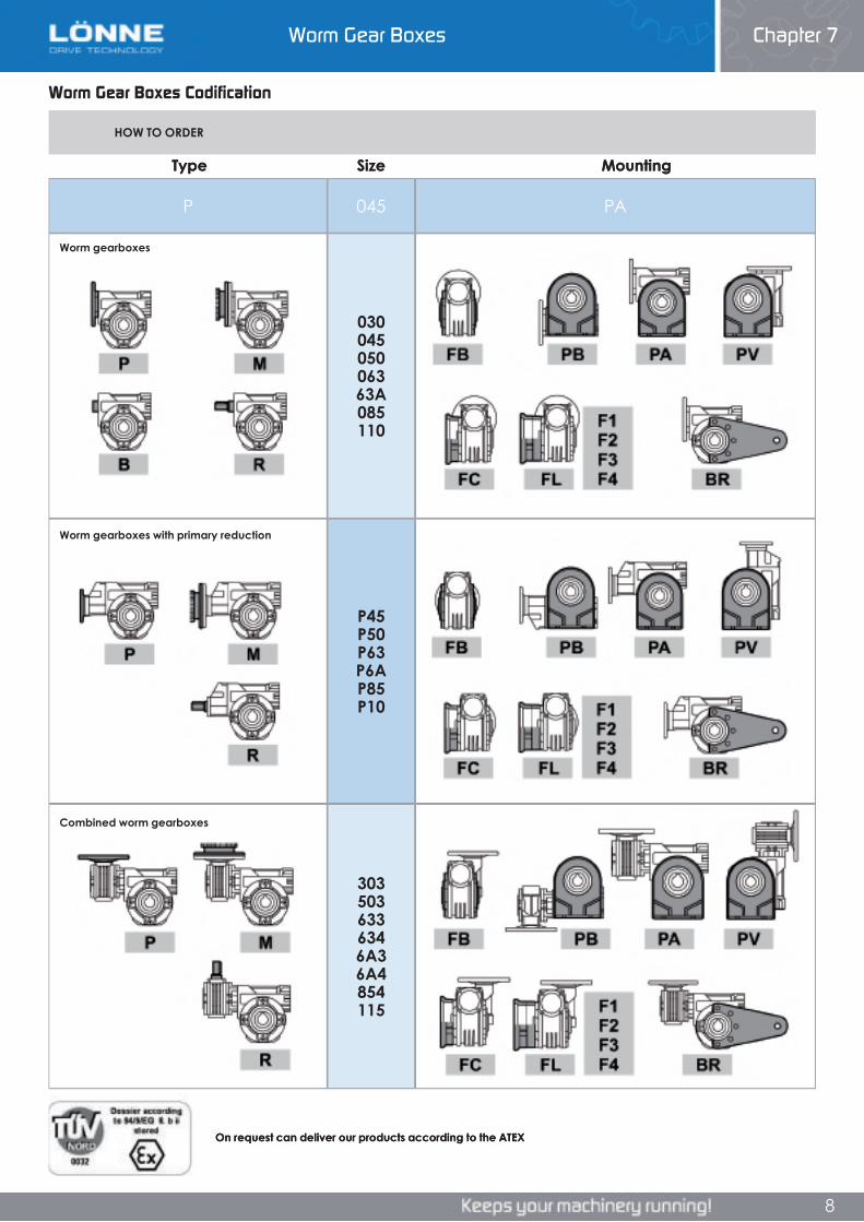
Worm Gear Boxes Codification
P 045 PA
03004505006363A085110
P45P50P63P6AP85P10
3035036336346A36A4854115
HOW TO ORDER
Type
Worm gearboxes with primary reduction
Worm gearboxes
Combined worm gearboxes
MountingSize
On request can deliver our products according to the ATEX
Worm Gear Boxes CodificationWorm Gear Boxes Codification
P 045 PA
03004505006363A085110
P45P50P63P6AP85P10
3035036336346A36A4854115
HOW TO ORDER
Type
Worm gearboxes with primary reduction
Worm gearboxes
Combined worm gearboxes
MountingSize
On request can deliver our products according to the ATEX
Chapter 7Worm Gear Boxes
8
P 045 PA
03004505006363A085110
P45P50P63P6AP85P10
3035036336346A36A4854115
HOW TO ORDER
Type
Worm gearboxes with primary reduction
Worm gearboxes
Combined worm gearboxes
MountingSize
On request can deliver our products according to the ATEX
8
Worm Gear Boxes Chapter 7
Worm Gear Boxes Chapter 7
9
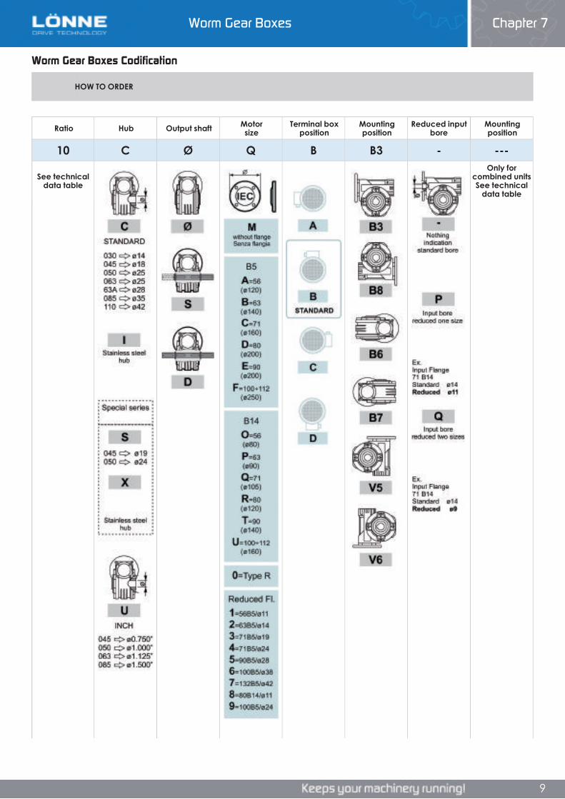
Worm Gear Boxes Codification
Ratio Hub Output shaft Motorsize
Terminal box position
Mounting position
Reduced input bore
Mounting position
10 C Ø Q B B3 - ---
See technical data table
Only forcombined units See technical
data table
HOW TO ORDER
Worm Gear Boxes Codification
Chapter 7
Worm Gear Boxes Codification
Ratio Hub Output shaft Motorsize
Terminal box position
Mounting position
Reduced input bore
Mounting position
10 C Ø Q B B3 - ---
See technical data table
Only forcombined units See technical
data table
HOW TO ORDER
Worm Gear Boxes
9
Ratio Hub Output shaft Motorsize
Terminal box position
Mounting position
Reduced input bore
Mounting position
10 C Ø Q B B3 - ---
See technical data table
Only forcombined units See technical
data table
HOW TO ORDER
9
Worm Gear Boxes Chapter 7
Worm Gear Boxes Chapter 7
10
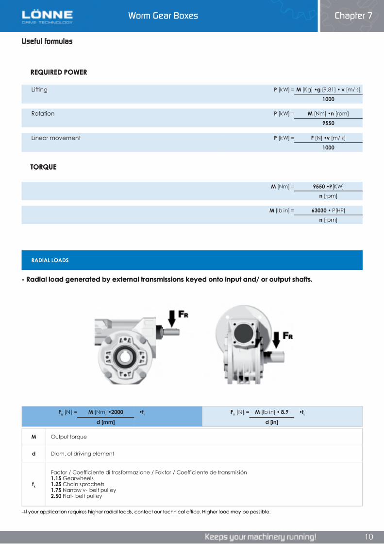
Useful formulas
M Output torque
d Diam. of driving element
fK
Factor / Coefficiente di trasformazione / Faktor / Coefficiente de transmisión 1.15 Gearwheels1.25 Chain sprochets 1.75 Narrow v- belt pulley2.50 Flat- belt pulley
RADIAL LOADS
Lifting P [kW] = M [Kg] •g [9.81] • v [m/ s]
1000
FR [N] = M [lb in] • 8.9 •fk
d [in]
FR [N] = M [Nm] •2000 •fk
d [mm]
Linear movement P [kW] = F [N] •v [m/ s]
1000
Rotation P [kW] = M [Nm] •n [rpm]
9550
M [Nm] = 9550 •P[KW]
n [rpm]
M [lb in] = 63030 • P[HP]
n [rpm]
REQUIRED POWER
- Radial load generated by external transmissions keyed onto input and/ or output shafts.
— If your application requires higher radial loads, contact our technical office. Higher load may be possible.
TORQUE
Useful formulasUseful formulas
M Output torque
d Diam. of driving element
fK
Factor / Coefficiente di trasformazione / Faktor / Coefficiente de transmisión 1.15 Gearwheels1.25 Chain sprochets 1.75 Narrow v- belt pulley2.50 Flat- belt pulley
RADIAL LOADS
Lifting P [kW] = M [Kg] •g [9.81] • v [m/ s]
1000
FR [N] = M [lb in] • 8.9 •fk
d [in]
FR [N] = M [Nm] •2000 •fk
d [mm]
Linear movement P [kW] = F [N] •v [m/ s]
1000
Rotation P [kW] = M [Nm] •n [rpm]
9550
M [Nm] = 9550 •P[KW]
n [rpm]
M [lb in] = 63030 • P[HP]
n [rpm]
REQUIRED POWER
- Radial load generated by external transmissions keyed onto input and/ or output shafts.
— If your application requires higher radial loads, contact our technical office. Higher load may be possible.
TORQUE
Chapter 7Worm Gear Boxes
10
M Output torque
d Diam. of driving element
fK
Factor / Coefficiente di trasformazione / Faktor / Coefficiente de transmisión 1.15 Gearwheels1.25 Chain sprochets 1.75 Narrow v- belt pulley2.50 Flat- belt pulley
RADIAL LOADS
Lifting P [kW] = M [Kg] •g [9.81] • v [m/ s]
1000
FR [N] = M [lb in] • 8.9 •fk
d [in]
FR [N] = M [Nm] •2000 •fk
d [mm]
Linear movement P [kW] = F [N] •v [m/ s]
1000
Rotation P [kW] = M [Nm] •n [rpm]
9550
M [Nm] = 9550 •P[KW]
n [rpm]
M [lb in] = 63030 • P[HP]
n [rpm]
REQUIRED POWER
- Radial load generated by external transmissions keyed onto input and/ or output shafts.
— If your application requires higher radial loads, contact our technical office. Higher load may be possible.
TORQUE
10
Worm Gear Boxes Chapter 7
Worm Gear Boxes Chapter 7
11
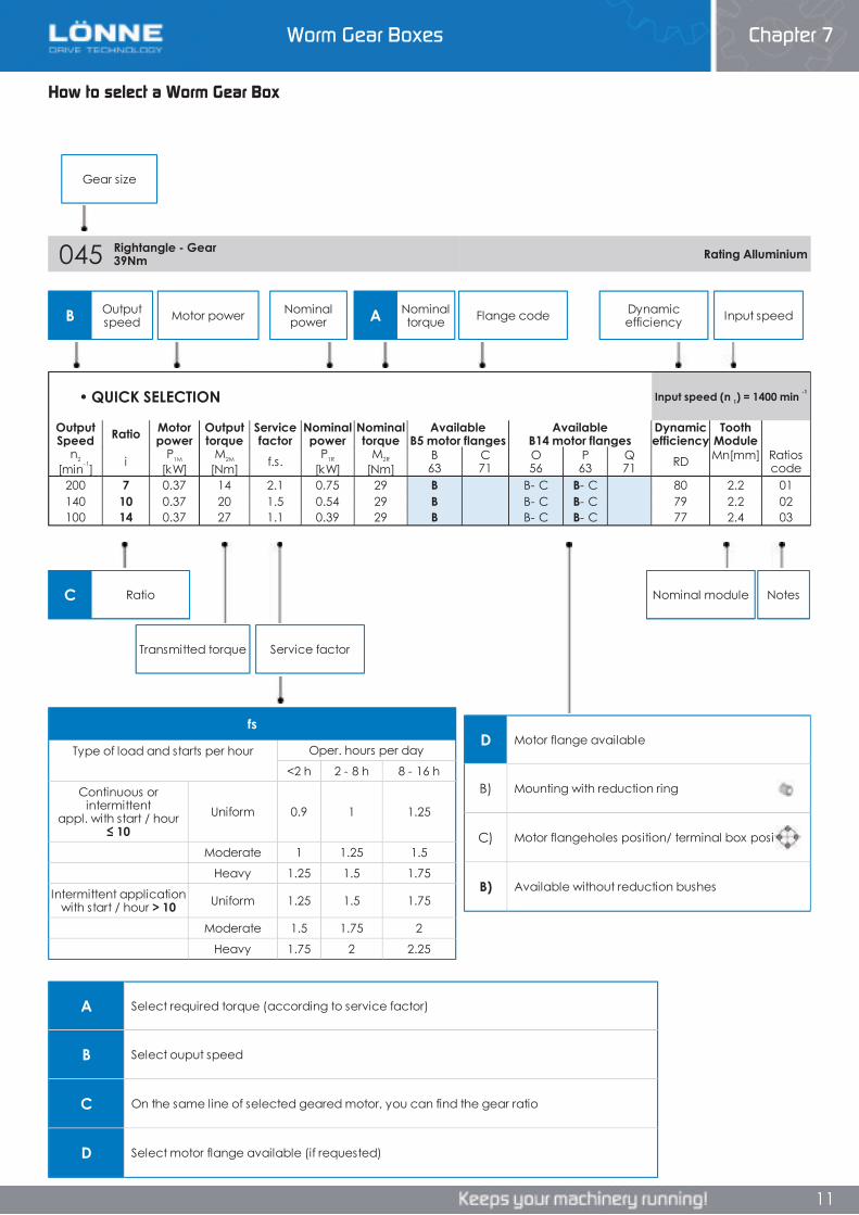
How to select a Worm Gear Box
B Output speed A Nominal
torque
C Ratio
045 Rightangle - Gear 39Nm Rating Alluminium
Gear size
Nominal powerMotor power Flange code Input speedDynamic
efficiency
Transmitted torque Service factor
Nominal module Notes
D Motor flange available
B) Mounting with reduction ring
C) Motor flangeholes position/ terminal box position
B) Available without reduction bushes
fs
Type of load and starts per hour Oper. hours per day
<2 h 2 - 8 h 8 - 16 h
Continuous or intermittent
appl. with start / hour ≤ 10
Uniform 0.9 1 1.25
Moderate 1 1.25 1.5
Heavy 1.25 1.5 1.75
Intermittent application with start / hour > 10 Uniform 1.25 1.5 1.75
Moderate 1.5 1.75 2
Heavy 1.75 2 2.25
A Select required torque (according to service factor)
B Select ouput speed
C On the same line of selected geared motor, you can find the gear ratio
D Select motor flange available (if requested)
• QUICK SELECTION Input speed (n 1) = 1400 min -1
Output Speed Ratio Motor
powerOutput torque
Service factor
Nominal power
Nominal torque
AvailableB5 motor flanges
AvailableB14 motor flanges
Dynamic efficiency
Tooth Module
n2
[min-1] i P1M
[kW]M2M
[Nm] f.s. P1R
[kW]M2R
[Nm]B63
C71
O56
P63
Q71 RD Mn [mm] Ratios
code200 7 0.37 14 2.1 0.75 29 B B- C B- C 80 2.2 01140 10 0.37 20 1.5 0.54 29 B B- C B- C 79 2.2 02100 14 0.37 27 1.1 0.39 29 B B- C B- C 77 2.4 03
How to select a Worm Gear Box
Chapter 7
How to select a Worm Gear Box
B Output speed A Nominal
torque
C Ratio
045 Rightangle - Gear 39Nm Rating Alluminium
Gear size
Nominal powerMotor power Flange code Input speedDynamic
efficiency
Transmitted torque Service factor
Nominal module Notes
D Motor flange available
B) Mounting with reduction ring
C) Motor flangeholes position/ terminal box position
B) Available without reduction bushes
fs
Type of load and starts per hour Oper. hours per day
<2 h 2 - 8 h 8 - 16 h
Continuous or intermittent
appl. with start / hour ≤ 10
Uniform 0.9 1 1.25
Moderate 1 1.25 1.5
Heavy 1.25 1.5 1.75
Intermittent application with start / hour > 10 Uniform 1.25 1.5 1.75
Moderate 1.5 1.75 2
Heavy 1.75 2 2.25
A Select required torque (according to service factor)
B Select ouput speed
C On the same line of selected geared motor, you can find the gear ratio
D Select motor flange available (if requested)
• QUICK SELECTION Input speed (n 1) = 1400 min -1
Output Speed Ratio Motor
powerOutput torque
Service factor
Nominal power
Nominal torque
AvailableB5 motor flanges
AvailableB14 motor flanges
Dynamic efficiency
Tooth Module
n2
[min-1] i P1M
[kW]M2M
[Nm] f.s. P1R
[kW]M2R
[Nm]B63
C71
O56
P63
Q71 RD Mn [mm] Ratios
code200 7 0.37 14 2.1 0.75 29 B B- C B- C 80 2.2 01140 10 0.37 20 1.5 0.54 29 B B- C B- C 79 2.2 02100 14 0.37 27 1.1 0.39 29 B B- C B- C 77 2.4 03
Worm Gear Boxes
11
B Output speed A Nominal
torque
C Ratio
045 Rightangle - Gear 39Nm Rating Alluminium
Gear size
Nominal powerMotor power Flange code Input speedDynamic
efficiency
Transmitted torque Service factor
Nominal module Notes
D Motor flange available
B) Mounting with reduction ring
C) Motor flangeholes position/ terminal box position
B) Available without reduction bushes
fs
Type of load and starts per hour Oper. hours per day
<2 h 2 - 8 h 8 - 16 h
Continuous or intermittent
appl. with start / hour ≤ 10
Uniform 0.9 1 1.25
Moderate 1 1.25 1.5
Heavy 1.25 1.5 1.75
Intermittent application with start / hour > 10 Uniform 1.25 1.5 1.75
Moderate 1.5 1.75 2
Heavy 1.75 2 2.25
A Select required torque (according to service factor)
B Select ouput speed
C On the same line of selected geared motor, you can find the gear ratio
D Select motor flange available (if requested)
• QUICK SELECTION Input speed (n 1) = 1400 min -1
Output Speed Ratio Motor
powerOutput torque
Service factor
Nominal power
Nominal torque
AvailableB5 motor flanges
AvailableB14 motor flanges
Dynamic efficiency
Tooth Module
n2
[min-1] i P1M
[kW]M2M
[Nm] f.s. P1R
[kW]M2R
[Nm]B63
C71
O56
P63
Q71 RD Mn [mm] Ratios
code200 7 0.37 14 2.1 0.75 29 B B- C B- C 80 2.2 01140 10 0.37 20 1.5 0.54 29 B B- C B- C 79 2.2 02100 14 0.37 27 1.1 0.39 29 B B- C B- C 77 2.4 03
11
Worm Gear Boxes Chapter 7

Worm Gear Boxes Chapter 7
12
Single Worm Gear Boxes 030
030 Rightangle - Gear 20Nm Rating Alluminium
RADIAL AND AXIAL LOADS
n2[min-1]
FA[N]
FR[N]
1400 20 100
n2[min-1]
FA[N]
FR[N]
200 120 600150 140 700100 160 80075 180 90050 200 100025 250 125015 280 1400
AGIP KLUBER SHELL MOBILTelium VSF 320 Syntheso D220 EP Tivela Oil WB Glygoyl 30 SHC 630
• QUICK SELECTION input speed (n 1)=1400 min-1
Outputspeed Ratio Motor
powerOutputtorque
Servicefactor
Nominalpower
Nominaltorque
AvailableB5 motor flanges
AvailableB14 motor flanges
Dynamiceffiency
ToothModule
n2
[min-1] i P1M
[kW]M2M
[Nm] f.s P1R
[kW]M2R
[Nm]A56
B63
O56
P63 RD Mn [mm] Ratios
code
280 5 0.18 5 3.2 0.57 16 B B- C 82 1.26 01200 7 0.18 7 2.3 0.42 16 B B- C 80 1.44 02140 10 0.18 10 1.7 0.30 16 B B- C 78 1.44 0393 15 0.18 13 1.3 0.24 18 B B- C 73 1.44 0470 20 0.18 17 1.0 0.19 18 B B- C 70 1.09 0547 30 0.12 15 1.3 0.16 20 B B- C 62 1.44 0635 40 0.12 19 1.0 0.12 19 B B- C 57 1.09 0723 61 0.09 19 1.0 0.09 19 B B- C 50 0.72 08
17.5 80 0.09 16 1.0 0.06 15 B B- C 48 0.56 09
Unit 030 is supplied with synthetic oil, providing “long life” lubrication. For mounting position V5- V6 please contact us.
See table 1 for lubrication and recommended quantity.
In table 2 please see possible radial loads and axial loads on the gearbox.
Motor Flanges Available
Input Shaft
C) Motor Flange Holes PositionB) Available on Request without reduction bushingB) Supplied with Reduction Bushing
Output Shaft
*Strong axial loads in the DX direction are not allowed.
LUBRICATION 030 OIL Quantity 0.03 Lt
Tab 2
Tab 1
Single Worm Gear Boxes 030
Chapter 7Worm Gear Boxes
12
030 Rightangle - Gear 20Nm Rating Alluminium
RADIAL AND AXIAL LOADS
n2[min-1]
FA[N]
FR[N]
1400 20 100
n2[min-1]
FA[N]
FR[N]
200 120 600150 140 700100 160 80075 180 90050 200 100025 250 125015 280 1400
AGIP KLUBER SHELL MOBILTelium VSF 320 Syntheso D220 EP Tivela Oil WB Glygoyl 30 SHC 630
• QUICK SELECTION input speed (n 1)=1400 min-1
Outputspeed Ratio Motor
powerOutputtorque
Servicefactor
Nominalpower
Nominaltorque
AvailableB5 motor flanges
AvailableB14 motor flanges
Dynamiceffiency
ToothModule
n2
[min-1] i P1M
[kW]M2M
[Nm] f.s P1R
[kW]M2R
[Nm]A56
B63
O56
P63 RD Mn [mm] Ratios
code
280 5 0.18 5 3.2 0.57 16 B B- C 82 1.26 01200 7 0.18 7 2.3 0.42 16 B B- C 80 1.44 02140 10 0.18 10 1.7 0.30 16 B B- C 78 1.44 0393 15 0.18 13 1.3 0.24 18 B B- C 73 1.44 0470 20 0.18 17 1.0 0.19 18 B B- C 70 1.09 0547 30 0.12 15 1.3 0.16 20 B B- C 62 1.44 0635 40 0.12 19 1.0 0.12 19 B B- C 57 1.09 0723 61 0.09 19 1.0 0.09 19 B B- C 50 0.72 08
17.5 80 0.09 16 1.0 0.06 15 B B- C 48 0.56 09
Unit 030 is supplied with synthetic oil, providing “long life” lubrication. For mounting position V5- V6 please contact us.
See table 1 for lubrication and recommended quantity.
In table 2 please see possible radial loads and axial loads on the gearbox.
Motor Flanges Available
Input Shaft
C) Motor Flange Holes PositionB) Available on Request without reduction bushingB) Supplied with Reduction Bushing
Output Shaft
*Strong axial loads in the DX direction are not allowed.
LUBRICATION 030 OIL Quantity 0.03 Lt
Tab 2
Tab 1
Worm Gear Boxes Chapter 7
12

Worm Gear Boxes Chapter 7
12
Single Worm Gear Boxes 030
030 Rightangle - Gear 20Nm Rating Alluminium
RADIAL AND AXIAL LOADS
n2[min-1]
FA[N]
FR[N]
1400 20 100
n2[min-1]
FA[N]
FR[N]
200 120 600150 140 700100 160 80075 180 90050 200 100025 250 125015 280 1400
AGIP KLUBER SHELL MOBILTelium VSF 320 Syntheso D220 EP Tivela Oil WB Glygoyl 30 SHC 630
• QUICK SELECTION input speed (n 1)=1400 min-1
Outputspeed Ratio Motor
powerOutputtorque
Servicefactor
Nominalpower
Nominaltorque
AvailableB5 motor flanges
AvailableB14 motor flanges
Dynamiceffiency
ToothModule
n2
[min-1] i P1M
[kW]M2M
[Nm] f.s P1R
[kW]M2R
[Nm]A56
B63
O56
P63 RD Mn [mm] Ratios
code
280 5 0.18 5 3.2 0.57 16 B B- C 82 1.26 01200 7 0.18 7 2.3 0.42 16 B B- C 80 1.44 02140 10 0.18 10 1.7 0.30 16 B B- C 78 1.44 0393 15 0.18 13 1.3 0.24 18 B B- C 73 1.44 0470 20 0.18 17 1.0 0.19 18 B B- C 70 1.09 0547 30 0.12 15 1.3 0.16 20 B B- C 62 1.44 0635 40 0.12 19 1.0 0.12 19 B B- C 57 1.09 0723 61 0.09 19 1.0 0.09 19 B B- C 50 0.72 08
17.5 80 0.09 16 1.0 0.06 15 B B- C 48 0.56 09
Unit 030 is supplied with synthetic oil, providing “long life” lubrication. For mounting position V5- V6 please contact us.
See table 1 for lubrication and recommended quantity.
In table 2 please see possible radial loads and axial loads on the gearbox.
Motor Flanges Available
Input Shaft
C) Motor Flange Holes PositionB) Available on Request without reduction bushingB) Supplied with Reduction Bushing
Output Shaft
*Strong axial loads in the DX direction are not allowed.
LUBRICATION 030 OIL Quantity 0.03 Lt
Tab 2
Tab 1
Single Worm Gear Boxes 030
Chapter 7Worm Gear Boxes
12
030 Rightangle - Gear 20Nm Rating Alluminium
RADIAL AND AXIAL LOADS
n2[min-1]
FA[N]
FR[N]
1400 20 100
n2[min-1]
FA[N]
FR[N]
200 120 600150 140 700100 160 80075 180 90050 200 100025 250 125015 280 1400
AGIP KLUBER SHELL MOBILTelium VSF 320 Syntheso D220 EP Tivela Oil WB Glygoyl 30 SHC 630
• QUICK SELECTION input speed (n 1)=1400 min-1
Outputspeed Ratio Motor
powerOutputtorque
Servicefactor
Nominalpower
Nominaltorque
AvailableB5 motor flanges
AvailableB14 motor flanges
Dynamiceffiency
ToothModule
n2
[min-1] i P1M
[kW]M2M
[Nm] f.s P1R
[kW]M2R
[Nm]A56
B63
O56
P63 RD Mn [mm] Ratios
code
280 5 0.18 5 3.2 0.57 16 B B- C 82 1.26 01200 7 0.18 7 2.3 0.42 16 B B- C 80 1.44 02140 10 0.18 10 1.7 0.30 16 B B- C 78 1.44 0393 15 0.18 13 1.3 0.24 18 B B- C 73 1.44 0470 20 0.18 17 1.0 0.19 18 B B- C 70 1.09 0547 30 0.12 15 1.3 0.16 20 B B- C 62 1.44 0635 40 0.12 19 1.0 0.12 19 B B- C 57 1.09 0723 61 0.09 19 1.0 0.09 19 B B- C 50 0.72 08
17.5 80 0.09 16 1.0 0.06 15 B B- C 48 0.56 09
Unit 030 is supplied with synthetic oil, providing “long life” lubrication. For mounting position V5- V6 please contact us.
See table 1 for lubrication and recommended quantity.
In table 2 please see possible radial loads and axial loads on the gearbox.
Motor Flanges Available
Input Shaft
C) Motor Flange Holes PositionB) Available on Request without reduction bushingB) Supplied with Reduction Bushing
Output Shaft
*Strong axial loads in the DX direction are not allowed.
LUBRICATION 030 OIL Quantity 0.03 Lt
Tab 2
Tab 1
Worm Gear Boxes Chapter 7
12
Worm Gear Boxes Chapter 7
13
Single Worm Gear Boxes 030
M. flanges Kit code øF A56B5 K030.4.041 120 61.563B5 K030.4.042 140 62.5
56B14 K030.4.046 80 61.563B14 K030.4.045 90 62.5
ød e g l m x kit codetype B 9 h6 10.2 3 20 58 - K030.5.006 PAM63type S - - - - - - -
H R S T U V Y W øZ kit codetype B 55 66 3 87 50 78 94 107 ø6.5 K030.9.022type S 52 66 3 87 52 90 91 104 ø6.5 KS030.9.023
3D dimensions on the web Rightangle - Gear 20Nm 030
Wormboxweight 1.05 kgP030FB... Basic wormbox
P030PB... FeetP030PA... Feet P030PV... Feet
P030FC... Output flange P030BR... Reaction arm
P030..S... Single Shaft P030..D... Double Shaft
R030FB... Input shaft
Type B øD E G L N O P Q Kit codeFC 50 +0,15
+0,05 6 6 50.5 23 68 80 7 1) K030.9.010 2) -
FL 60 +0,15+0,05 6 6 55.5 28 87 110 8.5 1) K045.9.010
2) -
Type S øD E G L N O P Q Kit codeF1 40 +0,15
+0,10 3.5 5.5 49 21.5 56 80 6.5 1) KS030.9.012 2) -
b1 c1 d1 e1 f1 l1 m1 n1 t2 o1type B 5 25 14 -0,005
-0,020 35.5 55 126 59 94.5 15.8 M5x14
type S - - - - - - - - - -
kit cod. K030.5.028 type B kit cod. K030.5.029 type B
Single Worm Gear Boxes 030
Chapter 7Worm Gear Boxes
Single Worm Gear Boxes 030
M. flanges Kit code øF A56B5 K030.4.041 120 61.563B5 K030.4.042 140 62.5
56B14 K030.4.046 80 61.563B14 K030.4.045 90 62.5
ød e g l m x kit codetype B 9 h6 10.2 3 20 58 - K030.5.006 PAM63type S - - - - - - -
H R S T U V Y W øZ kit codetype B 55 66 3 87 50 78 94 107 ø6.5 K030.9.022type S 52 66 3 87 52 90 91 104 ø6.5 KS030.9.023
3D dimensions on the web Rightangle - Gear 20Nm 030
Wormboxweight 1.05 kgP030FB... Basic wormbox
P030PB... FeetP030PA... Feet P030PV... Feet
P030FC... Output flange P030BR... Reaction arm
P030..S... Single Shaft P030..D... Double Shaft
R030FB... Input shaft
Type B øD E G L N O P Q Kit codeFC 50 +0,15
+0,05 6 6 50.5 23 68 80 7 1) K030.9.010 2) -
FL 60 +0,15+0,05 6 6 55.5 28 87 110 8.5 1) K045.9.010
2) -
Type S øD E G L N O P Q Kit codeF1 40 +0,15
+0,10 3.5 5.5 49 21.5 56 80 6.5 1) KS030.9.012 2) -
b1 c1 d1 e1 f1 l1 m1 n1 t2 o1type B 5 25 14 -0,005
-0,020 35.5 55 126 59 94.5 15.8 M5x14
type S - - - - - - - - - -
kit cod. K030.5.028 type B kit cod. K030.5.029 type B
13
M. flanges Kit code øF A56B5 K030.4.041 120 61.563B5 K030.4.042 140 62.5
56B14 K030.4.046 80 61.563B14 K030.4.045 90 62.5
ød e g l m x kit codetype B 9 h6 10.2 3 20 58 - K030.5.006 PAM63type S - - - - - - -
H R S T U V Y W øZ kit codetype B 55 66 3 87 50 78 94 107 ø6.5 K030.9.022type S 52 66 3 87 52 90 91 104 ø6.5 KS030.9.023
3D dimensions on the web Rightangle - Gear 20Nm 030
Wormboxweight 1.05 kgP030FB... Basic wormbox
P030PB... FeetP030PA... Feet P030PV... Feet
P030FC... Output flange P030BR... Reaction arm
P030..S... Single Shaft P030..D... Double Shaft
R030FB... Input shaft
Type B øD E G L N O P Q Kit codeFC 50 +0,15
+0,05 6 6 50.5 23 68 80 7 1) K030.9.010 2) -
FL 60 +0,15+0,05 6 6 55.5 28 87 110 8.5 1) K045.9.010
2) -
Type S øD E G L N O P Q Kit codeF1 40 +0,15
+0,10 3.5 5.5 49 21.5 56 80 6.5 1) KS030.9.012 2) -
b1 c1 d1 e1 f1 l1 m1 n1 t2 o1type B 5 25 14 -0,005
-0,020 35.5 55 126 59 94.5 15.8 M5x14
type S - - - - - - - - - -
kit cod. K030.5.028 type B kit cod. K030.5.029 type B
Worm Gear Boxes Chapter 7
13
Worm Gear Boxes Chapter 7
14
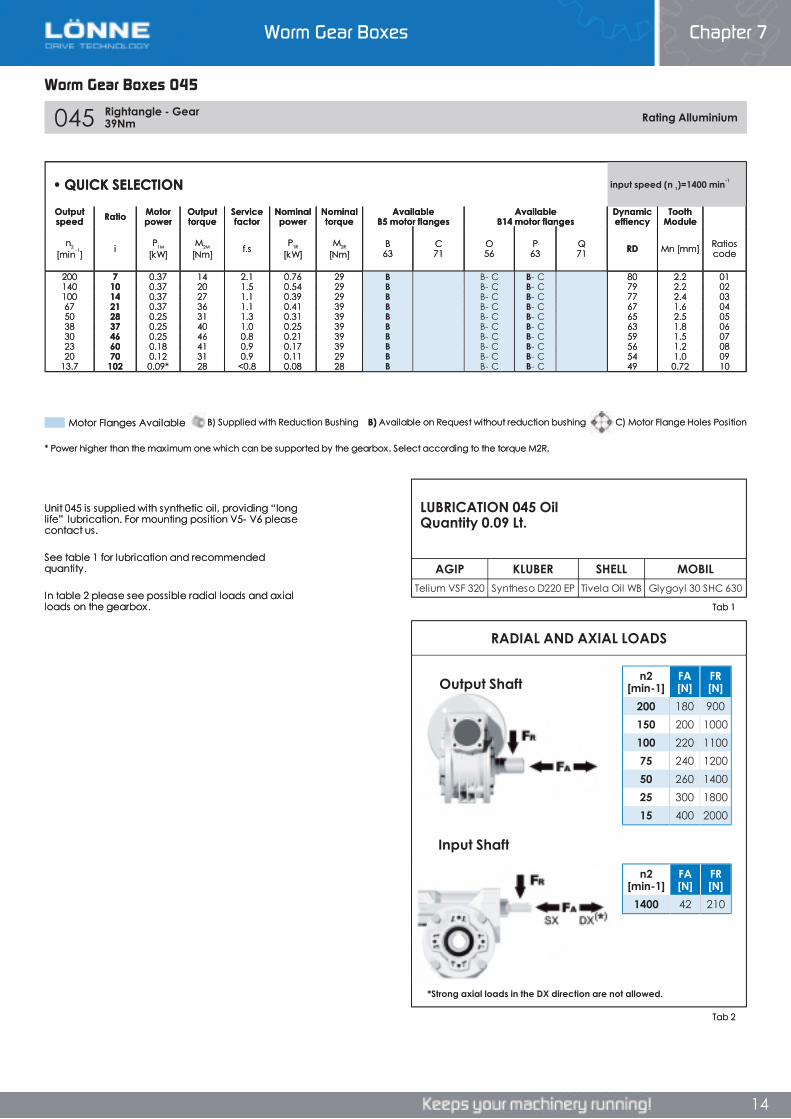
Worm Gear Boxes 045
RADIAL AND AXIAL LOADS
AGIP KLUBER SHELL MOBILTelium VSF 320 Syntheso D220 EP Tivela Oil WB Glygoyl 30 SHC 630
045 Rightangle - Gear 39Nm Rating Alluminium
n2[min-1]
FA[N]
FR[N]
1400 42 210
n2[min-1]
FA[N]
FR[N]
200 180 900150 200 1000100 220 110075 240 120050 260 140025 300 180015 400 2000
• QUICK SELECTION input speed (n 1)=1400 min-1
Outputspeed Ratio Motor
powerOutputtorque
Servicefactor
Nominalpower
Nominaltorque
AvailableB5 motor flanges
AvailableB14 motor flanges
Dynamiceffiency
ToothModule
n2
[min-1] i P1M
[kW]M2M
[Nm] f.s P1R
[kW]M2R
[Nm]B63
C71
O56
P63
Q71 RD Mn [mm] Ratios
code
200 7 0.37 14 2.1 0.76 29 B B- C B- C 80 2.2 01140 10 0.37 20 1.5 0.54 29 B B- C B- C 79 2.2 02100 14 0.37 27 1.1 0.39 29 B B- C B- C 77 2.4 0367 21 0.37 36 1.1 0.41 39 B B- C B- C 67 1.6 0450 28 0.25 31 1.3 0.31 39 B B- C B- C 65 2.5 0538 37 0.25 40 1.0 0.25 39 B B- C B- C 63 1.8 0630 46 0.25 46 0.8 0.21 39 B B- C B- C 59 1.5 0723 60 0.18 41 0.9 0.17 39 B B- C B- C 56 1.2 0820 70 0.12 31 0.9 0.11 29 B B- C B- C 54 1.0 09
13.7 102 0.09* 28 <0.8 0.08 28 B B- C B- C 49 0.72 10
Unit 045 is supplied with synthetic oil, providing “long life” lubrication. For mounting position V5- V6 please contact us.
See table 1 for lubrication and recommended quantity.
In table 2 please see possible radial loads and axial loads on the gearbox.
*Strong axial loads in the DX direction are not allowed.
* Power higher than the maximum one which can be supported by the gearbox. Select according to the torque M2R.
Input Shaft
Tab 1
Output Shaft
Tab 2
LUBRICATION 045 Oil Quantity 0.09 Lt.
Motor Flanges Available C) Motor Flange Holes PositionB) Available on Request without reduction bushingB) Supplied with Reduction Bushing
Worm Gear Boxes 045
Chapter 7Worm Gear Boxes
Worm Gear Boxes 045
RADIAL AND AXIAL LOADS
AGIP KLUBER SHELL MOBILTelium VSF 320 Syntheso D220 EP Tivela Oil WB Glygoyl 30 SHC 630
045 Rightangle - Gear 39Nm Rating Alluminium
n2[min-1]
FA[N]
FR[N]
1400 42 210
n2[min-1]
FA[N]
FR[N]
200 180 900150 200 1000100 220 110075 240 120050 260 140025 300 180015 400 2000
• QUICK SELECTION input speed (n 1)=1400 min-1
Outputspeed Ratio Motor
powerOutputtorque
Servicefactor
Nominalpower
Nominaltorque
AvailableB5 motor flanges
AvailableB14 motor flanges
Dynamiceffiency
ToothModule
n2
[min-1] i P1M
[kW]M2M
[Nm] f.s P1R
[kW]M2R
[Nm]B63
C71
O56
P63
Q71 RD Mn [mm] Ratios
code
200 7 0.37 14 2.1 0.76 29 B B- C B- C 80 2.2 01140 10 0.37 20 1.5 0.54 29 B B- C B- C 79 2.2 02100 14 0.37 27 1.1 0.39 29 B B- C B- C 77 2.4 0367 21 0.37 36 1.1 0.41 39 B B- C B- C 67 1.6 0450 28 0.25 31 1.3 0.31 39 B B- C B- C 65 2.5 0538 37 0.25 40 1.0 0.25 39 B B- C B- C 63 1.8 0630 46 0.25 46 0.8 0.21 39 B B- C B- C 59 1.5 0723 60 0.18 41 0.9 0.17 39 B B- C B- C 56 1.2 0820 70 0.12 31 0.9 0.11 29 B B- C B- C 54 1.0 09
13.7 102 0.09* 28 <0.8 0.08 28 B B- C B- C 49 0.72 10
Unit 045 is supplied with synthetic oil, providing “long life” lubrication. For mounting position V5- V6 please contact us.
See table 1 for lubrication and recommended quantity.
In table 2 please see possible radial loads and axial loads on the gearbox.
*Strong axial loads in the DX direction are not allowed.
* Power higher than the maximum one which can be supported by the gearbox. Select according to the torque M2R.
Input Shaft
Tab 1
Output Shaft
Tab 2
LUBRICATION 045 Oil Quantity 0.09 Lt.
Motor Flanges Available C) Motor Flange Holes PositionB) Available on Request without reduction bushingB) Supplied with Reduction Bushing
14
RADIAL AND AXIAL LOADS
AGIP KLUBER SHELL MOBILTelium VSF 320 Syntheso D220 EP Tivela Oil WB Glygoyl 30 SHC 630
045 Rightangle - Gear 39Nm Rating Alluminium
n2[min-1]
FA[N]
FR[N]
1400 42 210
n2[min-1]
FA[N]
FR[N]
200 180 900150 200 1000100 220 110075 240 120050 260 140025 300 180015 400 2000
• QUICK SELECTION input speed (n 1)=1400 min-1
Outputspeed Ratio Motor
powerOutputtorque
Servicefactor
Nominalpower
Nominaltorque
AvailableB5 motor flanges
AvailableB14 motor flanges
Dynamiceffiency
ToothModule
n2
[min-1] i P1M
[kW]M2M
[Nm] f.s P1R
[kW]M2R
[Nm]B63
C71
O56
P63
Q71 RD Mn [mm] Ratios
code
200 7 0.37 14 2.1 0.76 29 B B- C B- C 80 2.2 01140 10 0.37 20 1.5 0.54 29 B B- C B- C 79 2.2 02100 14 0.37 27 1.1 0.39 29 B B- C B- C 77 2.4 0367 21 0.37 36 1.1 0.41 39 B B- C B- C 67 1.6 0450 28 0.25 31 1.3 0.31 39 B B- C B- C 65 2.5 0538 37 0.25 40 1.0 0.25 39 B B- C B- C 63 1.8 0630 46 0.25 46 0.8 0.21 39 B B- C B- C 59 1.5 0723 60 0.18 41 0.9 0.17 39 B B- C B- C 56 1.2 0820 70 0.12 31 0.9 0.11 29 B B- C B- C 54 1.0 09
13.7 102 0.09* 28 <0.8 0.08 28 B B- C B- C 49 0.72 10
Unit 045 is supplied with synthetic oil, providing “long life” lubrication. For mounting position V5- V6 please contact us.
See table 1 for lubrication and recommended quantity.
In table 2 please see possible radial loads and axial loads on the gearbox.
*Strong axial loads in the DX direction are not allowed.
* Power higher than the maximum one which can be supported by the gearbox. Select according to the torque M2R.
Input Shaft
Tab 1
Output Shaft
Tab 2
LUBRICATION 045 Oil Quantity 0.09 Lt.
Motor Flanges Available C) Motor Flange Holes PositionB) Available on Request without reduction bushingB) Supplied with Reduction Bushing
Worm Gear Boxes Chapter 7
14
Worm Gear Boxes Chapter 7
14
Worm Gear Boxes 045
RADIAL AND AXIAL LOADS
AGIP KLUBER SHELL MOBILTelium VSF 320 Syntheso D220 EP Tivela Oil WB Glygoyl 30 SHC 630
045 Rightangle - Gear 39Nm Rating Alluminium
n2[min-1]
FA[N]
FR[N]
1400 42 210
n2[min-1]
FA[N]
FR[N]
200 180 900150 200 1000100 220 110075 240 120050 260 140025 300 180015 400 2000
• QUICK SELECTION input speed (n 1)=1400 min-1
Outputspeed Ratio Motor
powerOutputtorque
Servicefactor
Nominalpower
Nominaltorque
AvailableB5 motor flanges
AvailableB14 motor flanges
Dynamiceffiency
ToothModule
n2
[min-1] i P1M
[kW]M2M
[Nm] f.s P1R
[kW]M2R
[Nm]B63
C71
O56
P63
Q71 RD Mn [mm] Ratios
code
200 7 0.37 14 2.1 0.76 29 B B- C B- C 80 2.2 01140 10 0.37 20 1.5 0.54 29 B B- C B- C 79 2.2 02100 14 0.37 27 1.1 0.39 29 B B- C B- C 77 2.4 0367 21 0.37 36 1.1 0.41 39 B B- C B- C 67 1.6 0450 28 0.25 31 1.3 0.31 39 B B- C B- C 65 2.5 0538 37 0.25 40 1.0 0.25 39 B B- C B- C 63 1.8 0630 46 0.25 46 0.8 0.21 39 B B- C B- C 59 1.5 0723 60 0.18 41 0.9 0.17 39 B B- C B- C 56 1.2 0820 70 0.12 31 0.9 0.11 29 B B- C B- C 54 1.0 09
13.7 102 0.09* 28 <0.8 0.08 28 B B- C B- C 49 0.72 10
Unit 045 is supplied with synthetic oil, providing “long life” lubrication. For mounting position V5- V6 please contact us.
See table 1 for lubrication and recommended quantity.
In table 2 please see possible radial loads and axial loads on the gearbox.
*Strong axial loads in the DX direction are not allowed.
* Power higher than the maximum one which can be supported by the gearbox. Select according to the torque M2R.
Input Shaft
Tab 1
Output Shaft
Tab 2
LUBRICATION 045 Oil Quantity 0.09 Lt.
Motor Flanges Available C) Motor Flange Holes PositionB) Available on Request without reduction bushingB) Supplied with Reduction Bushing
Worm Gear Boxes 045
Chapter 7Worm Gear Boxes
Worm Gear Boxes 045
RADIAL AND AXIAL LOADS
AGIP KLUBER SHELL MOBILTelium VSF 320 Syntheso D220 EP Tivela Oil WB Glygoyl 30 SHC 630
045 Rightangle - Gear 39Nm Rating Alluminium
n2[min-1]
FA[N]
FR[N]
1400 42 210
n2[min-1]
FA[N]
FR[N]
200 180 900150 200 1000100 220 110075 240 120050 260 140025 300 180015 400 2000
• QUICK SELECTION input speed (n 1)=1400 min-1
Outputspeed Ratio Motor
powerOutputtorque
Servicefactor
Nominalpower
Nominaltorque
AvailableB5 motor flanges
AvailableB14 motor flanges
Dynamiceffiency
ToothModule
n2
[min-1] i P1M
[kW]M2M
[Nm] f.s P1R
[kW]M2R
[Nm]B63
C71
O56
P63
Q71 RD Mn [mm] Ratios
code
200 7 0.37 14 2.1 0.76 29 B B- C B- C 80 2.2 01140 10 0.37 20 1.5 0.54 29 B B- C B- C 79 2.2 02100 14 0.37 27 1.1 0.39 29 B B- C B- C 77 2.4 0367 21 0.37 36 1.1 0.41 39 B B- C B- C 67 1.6 0450 28 0.25 31 1.3 0.31 39 B B- C B- C 65 2.5 0538 37 0.25 40 1.0 0.25 39 B B- C B- C 63 1.8 0630 46 0.25 46 0.8 0.21 39 B B- C B- C 59 1.5 0723 60 0.18 41 0.9 0.17 39 B B- C B- C 56 1.2 0820 70 0.12 31 0.9 0.11 29 B B- C B- C 54 1.0 09
13.7 102 0.09* 28 <0.8 0.08 28 B B- C B- C 49 0.72 10
Unit 045 is supplied with synthetic oil, providing “long life” lubrication. For mounting position V5- V6 please contact us.
See table 1 for lubrication and recommended quantity.
In table 2 please see possible radial loads and axial loads on the gearbox.
*Strong axial loads in the DX direction are not allowed.
* Power higher than the maximum one which can be supported by the gearbox. Select according to the torque M2R.
Input Shaft
Tab 1
Output Shaft
Tab 2
LUBRICATION 045 Oil Quantity 0.09 Lt.
Motor Flanges Available C) Motor Flange Holes PositionB) Available on Request without reduction bushingB) Supplied with Reduction Bushing
14
RADIAL AND AXIAL LOADS
AGIP KLUBER SHELL MOBILTelium VSF 320 Syntheso D220 EP Tivela Oil WB Glygoyl 30 SHC 630
045 Rightangle - Gear 39Nm Rating Alluminium
n2[min-1]
FA[N]
FR[N]
1400 42 210
n2[min-1]
FA[N]
FR[N]
200 180 900150 200 1000100 220 110075 240 120050 260 140025 300 180015 400 2000
• QUICK SELECTION input speed (n 1)=1400 min-1
Outputspeed Ratio Motor
powerOutputtorque
Servicefactor
Nominalpower
Nominaltorque
AvailableB5 motor flanges
AvailableB14 motor flanges
Dynamiceffiency
ToothModule
n2
[min-1] i P1M
[kW]M2M
[Nm] f.s P1R
[kW]M2R
[Nm]B63
C71
O56
P63
Q71 RD Mn [mm] Ratios
code
200 7 0.37 14 2.1 0.76 29 B B- C B- C 80 2.2 01140 10 0.37 20 1.5 0.54 29 B B- C B- C 79 2.2 02100 14 0.37 27 1.1 0.39 29 B B- C B- C 77 2.4 0367 21 0.37 36 1.1 0.41 39 B B- C B- C 67 1.6 0450 28 0.25 31 1.3 0.31 39 B B- C B- C 65 2.5 0538 37 0.25 40 1.0 0.25 39 B B- C B- C 63 1.8 0630 46 0.25 46 0.8 0.21 39 B B- C B- C 59 1.5 0723 60 0.18 41 0.9 0.17 39 B B- C B- C 56 1.2 0820 70 0.12 31 0.9 0.11 29 B B- C B- C 54 1.0 09
13.7 102 0.09* 28 <0.8 0.08 28 B B- C B- C 49 0.72 10
Unit 045 is supplied with synthetic oil, providing “long life” lubrication. For mounting position V5- V6 please contact us.
See table 1 for lubrication and recommended quantity.
In table 2 please see possible radial loads and axial loads on the gearbox.
*Strong axial loads in the DX direction are not allowed.
* Power higher than the maximum one which can be supported by the gearbox. Select according to the torque M2R.
Input Shaft
Tab 1
Output Shaft
Tab 2
LUBRICATION 045 Oil Quantity 0.09 Lt.
Motor Flanges Available C) Motor Flange Holes PositionB) Available on Request without reduction bushingB) Supplied with Reduction Bushing
Worm Gear Boxes Chapter 7
14
Worm Gear Boxes Chapter 7
15
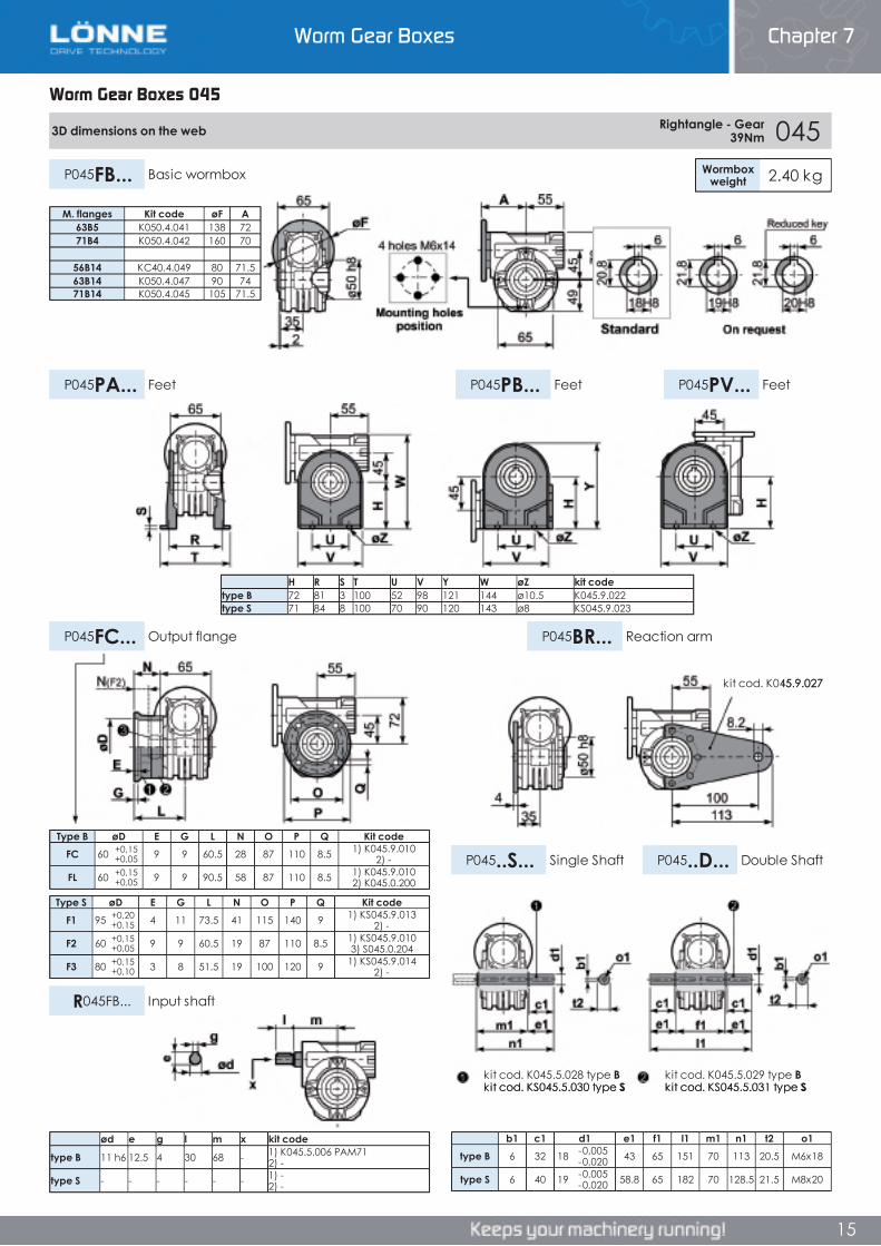
Worm Gear Boxes 045
M. flanges Kit code øF A63B5 K050.4.041 138 7271B4 K050.4.042 160 70
56B14 KC40.4.049 80 71.563B14 K050.4.047 90 7471B14 K050.4.045 105 71.5
H R S T U V Y W øZ kit codetype B 72 81 3 100 52 98 121 144 ø10.5 K045.9.022type S 71 84 8 100 70 90 120 143 ø8 KS045.9.023
ød e g l m x kit code
type B 11 h6 12.5 4 30 68 - 1) K045.5.006 PAM71 2) -
type S - - - - - - 1) -2) -
3D dimensions on the web Rightangle - Gear 39Nm 045
Wormboxweight 2.40 kgP045FB... Basic wormbox
P045PB... FeetP045PA... Feet P045PV... Feet
P045FC... Output flange P045BR... Reaction arm
P045..S... Single Shaft P045..D... Double Shaft
R045FB... Input shaft
Type S øD E G L N O P Q Kit codeF1 95 +0,20
+0,15 4 11 73.5 41 115 140 9 1) KS045.9.013 2) -
F2 60 +0,15+0,05 9 9 60.5 19 87 110 8.5 1) KS045.9.010
3) S045.0.204
F3 80 +0,15+0,10 3 8 51.5 19 100 120 9 1) KS045.9.014
2) -
Type B øD E G L N O P Q Kit codeFC 60 +0,15
+0,05 9 9 60.5 28 87 110 8.5 1) K045.9.010 2) -
FL 60 +0,15+0,05 9 9 90.5 58 87 110 8.5 1) K045.9.010
2) K045.0.200
b1 c1 d1 e1 f1 l1 m1 n1 t2 o1type B 6 32 18 -0,005
-0,020 43 65 151 70 113 20.5 M6x18
type S 6 40 19 -0,005-0,020 58.8 65 182 70 128.5 21.5 M8x20
kit cod. K045.9.027
kit cod. K045.5.028 type Bkit cod. KS045.5.030 type S
kit cod. K045.5.029 type Bkit cod. KS045.5.031 type S
Worm Gear Boxes 045
Chapter 7Worm Gear Boxes
Worm Gear Boxes 045
M. flanges Kit code øF A63B5 K050.4.041 138 7271B4 K050.4.042 160 70
56B14 KC40.4.049 80 71.563B14 K050.4.047 90 7471B14 K050.4.045 105 71.5
H R S T U V Y W øZ kit codetype B 72 81 3 100 52 98 121 144 ø10.5 K045.9.022type S 71 84 8 100 70 90 120 143 ø8 KS045.9.023
ød e g l m x kit code
type B 11 h6 12.5 4 30 68 - 1) K045.5.006 PAM71 2) -
type S - - - - - - 1) -2) -
3D dimensions on the web Rightangle - Gear 39Nm 045
Wormboxweight 2.40 kgP045FB... Basic wormbox
P045PB... FeetP045PA... Feet P045PV... Feet
P045FC... Output flange P045BR... Reaction arm
P045..S... Single Shaft P045..D... Double Shaft
R045FB... Input shaft
Type S øD E G L N O P Q Kit codeF1 95 +0,20
+0,15 4 11 73.5 41 115 140 9 1) KS045.9.013 2) -
F2 60 +0,15+0,05 9 9 60.5 19 87 110 8.5 1) KS045.9.010
3) S045.0.204
F3 80 +0,15+0,10 3 8 51.5 19 100 120 9 1) KS045.9.014
2) -
Type B øD E G L N O P Q Kit codeFC 60 +0,15
+0,05 9 9 60.5 28 87 110 8.5 1) K045.9.010 2) -
FL 60 +0,15+0,05 9 9 90.5 58 87 110 8.5 1) K045.9.010
2) K045.0.200
b1 c1 d1 e1 f1 l1 m1 n1 t2 o1type B 6 32 18 -0,005
-0,020 43 65 151 70 113 20.5 M6x18
type S 6 40 19 -0,005-0,020 58.8 65 182 70 128.5 21.5 M8x20
kit cod. K045.9.027
kit cod. K045.5.028 type Bkit cod. KS045.5.030 type S
kit cod. K045.5.029 type Bkit cod. KS045.5.031 type S
15
M. flanges Kit code øF A63B5 K050.4.041 138 7271B4 K050.4.042 160 70
56B14 KC40.4.049 80 71.563B14 K050.4.047 90 7471B14 K050.4.045 105 71.5
H R S T U V Y W øZ kit codetype B 72 81 3 100 52 98 121 144 ø10.5 K045.9.022type S 71 84 8 100 70 90 120 143 ø8 KS045.9.023
ød e g l m x kit code
type B 11 h6 12.5 4 30 68 - 1) K045.5.006 PAM71 2) -
type S - - - - - - 1) -2) -
3D dimensions on the web Rightangle - Gear 39Nm 045
Wormboxweight 2.40 kgP045FB... Basic wormbox
P045PB... FeetP045PA... Feet P045PV... Feet
P045FC... Output flange P045BR... Reaction arm
P045..S... Single Shaft P045..D... Double Shaft
R045FB... Input shaft
Type S øD E G L N O P Q Kit codeF1 95 +0,20
+0,15 4 11 73.5 41 115 140 9 1) KS045.9.013 2) -
F2 60 +0,15+0,05 9 9 60.5 19 87 110 8.5 1) KS045.9.010
3) S045.0.204
F3 80 +0,15+0,10 3 8 51.5 19 100 120 9 1) KS045.9.014
2) -
Type B øD E G L N O P Q Kit codeFC 60 +0,15
+0,05 9 9 60.5 28 87 110 8.5 1) K045.9.010 2) -
FL 60 +0,15+0,05 9 9 90.5 58 87 110 8.5 1) K045.9.010
2) K045.0.200
b1 c1 d1 e1 f1 l1 m1 n1 t2 o1type B 6 32 18 -0,005
-0,020 43 65 151 70 113 20.5 M6x18
type S 6 40 19 -0,005-0,020 58.8 65 182 70 128.5 21.5 M8x20
kit cod. K045.9.027
kit cod. K045.5.028 type Bkit cod. KS045.5.030 type S
kit cod. K045.5.029 type Bkit cod. KS045.5.031 type S
Worm Gear Boxes Chapter 7
15
Worm Gear Boxes Chapter 7
16
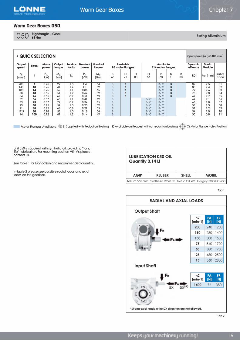
Worm Gear Boxes 050
050 Rightangle - Gear 69Nm Rating Alluminium
AGIP KLUBER SHELL MOBILTelium VSF 320 Syntheso D220 EP Tivela Oil WB Glygoyl 30 SHC 630
RADIAL AND AXIAL LOADS
n2[min-1]
FA[N]
FR[N]
1400 76 380
n2[min-1]
FA[N]
FR[N]
200 240 1200150 280 1400100 300 150075 340 170050 380 190025 480 250015 560 2800
• QUICK SELECTION input speed (n 1)=1400 min-1
Outputspeed Ratio Motor
powerOutputtorque
Servicefactor
Nominalpower
Nominaltorque
AvailableB5 motor flanges
AvailableB14 motor flanges
Dynamiceffiency
ToothModule
n2
[min-1] i P1M
[kW]M2M
[Nm] f.s P1R
[kW]M2R
[Nm]B63
C71
D80
O56
P63
Q71
R80 RD Mn [mm] Ratios
code
200 7 0.75 29 1.8 1.4 54 B B B- C B 82 2.5 01140 10 0.75 41 1.4 1.1 59 B B B- C B 80 2.4 02100 14 0.75 57 1.1 0.86 65 B B B- C B 79 2.6 0378 18 0.55 51 1.2 0.64 59 B B B- C B 75 2.0 0454 26 0.55 67 0.9 0.51 63 B B B- C B 69 2.7 0539 36 0.37 63 1.1 0.41 69 B B- C B- C 69 2.1 0633 43 0.37 72 0.9 0.34 65 B B- C B- C 66 1.8 0723 60 0.25 59 1.0 0.25 59 B B- C B- C 58 1.3 0821 68 0.25 66 0.8 0.21 55 B B- C B- C 57 1.2 09
17.5 80 0.18 53 1.0 0.18 54 B B- C B- C 54 1.0 1014 100 0.12 41 1.2 0.14 49 B B- C B- C 50 0.8 11
Unit 050 is supplied with synthetic oil, providing “long life” lubrication. For mounting position V5- V6 please contact us.
See table 1 for lubrication and recommended quantity.
In table 2 please see possible radial loads and axial loads on the gearbox.
Output Shaft
Input Shaft
LUBRICATION 050 OIL Quantity 0.14 Lt
Tab 2
Tab 1
*Strong axial loads in the DX direction are not allowed.
B) Supplied with Reduction Bushing B) Available on Request without reduction bushing C) Motor Flange Holes PositionMotor Flanges Available
Worm Gear Boxes 050
Chapter 7Worm Gear Boxes
16
050 Rightangle - Gear 69Nm Rating Alluminium
AGIP KLUBER SHELL MOBILTelium VSF 320 Syntheso D220 EP Tivela Oil WB Glygoyl 30 SHC 630
RADIAL AND AXIAL LOADS
n2[min-1]
FA[N]
FR[N]
1400 76 380
n2[min-1]
FA[N]
FR[N]
200 240 1200150 280 1400100 300 150075 340 170050 380 190025 480 250015 560 2800
• QUICK SELECTION input speed (n 1)=1400 min-1
Outputspeed Ratio Motor
powerOutputtorque
Servicefactor
Nominalpower
Nominaltorque
AvailableB5 motor flanges
AvailableB14 motor flanges
Dynamiceffiency
ToothModule
n2
[min-1] i P1M
[kW]M2M
[Nm] f.s P1R
[kW]M2R
[Nm]B63
C71
D80
O56
P63
Q71
R80 RD Mn [mm] Ratios
code
200 7 0.75 29 1.8 1.4 54 B B B- C B 82 2.5 01140 10 0.75 41 1.4 1.1 59 B B B- C B 80 2.4 02100 14 0.75 57 1.1 0.86 65 B B B- C B 79 2.6 0378 18 0.55 51 1.2 0.64 59 B B B- C B 75 2.0 0454 26 0.55 67 0.9 0.51 63 B B B- C B 69 2.7 0539 36 0.37 63 1.1 0.41 69 B B- C B- C 69 2.1 0633 43 0.37 72 0.9 0.34 65 B B- C B- C 66 1.8 0723 60 0.25 59 1.0 0.25 59 B B- C B- C 58 1.3 0821 68 0.25 66 0.8 0.21 55 B B- C B- C 57 1.2 09
17.5 80 0.18 53 1.0 0.18 54 B B- C B- C 54 1.0 1014 100 0.12 41 1.2 0.14 49 B B- C B- C 50 0.8 11
Unit 050 is supplied with synthetic oil, providing “long life” lubrication. For mounting position V5- V6 please contact us.
See table 1 for lubrication and recommended quantity.
In table 2 please see possible radial loads and axial loads on the gearbox.
Output Shaft
Input Shaft
LUBRICATION 050 OIL Quantity 0.14 Lt
Tab 2
Tab 1
*Strong axial loads in the DX direction are not allowed.
B) Supplied with Reduction Bushing B) Available on Request without reduction bushing C) Motor Flange Holes PositionMotor Flanges Available
Worm Gear Boxes Chapter 7
16
Worm Gear Boxes Chapter 7
17
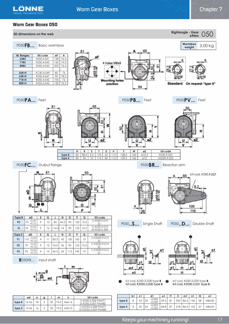
Worm Gear Boxes 050
3D dimensions on the web Rightangle - Gear 69Nm 050
Wormboxweight 3.00 kgP050FB... Basic wormbox
P050PB... FeetP050PA... Feet P050PV... Feet
P050FC... Output flange P050BR... Reaction arm
P050..S... Single Shaft P050..D... Double Shaft
R050FB... Input shaft
Type B øD E G L N O P Q Kit codeFC 70 +0,20
+0,15 9 12 85 44.5 90 123 10.5 1) K050.9.010 2) -
FL 70 +0,20+0,15 9 12 114.5 74 90 123 10.5 1) K050.9.010
2) K050.0.200
Type S øD E G L N O P Q Kit codeF1 110 +0,20
+0,15 4 11 83.5 43 130 160 10 1) KS050.9.012 2) -
F2 70 +0,20+0,15 9 12 76.5 36 90 123 10.5 1) KS050.9.014
2) -
F3 95 +0,20+0,15 4 10 66.5 26 115 140 10 1) KS050.9.013
2) -
b1 c1 d1 e1 f1 l1 m1 n1 t2 o1type B 8 52 25 -0,005
-0,020 59.5 81 200 86.5 146 28 M8x20
type S 8 50 24 -0,005-0,020 68.8 81 218 86.5 155 27 M8x20
M. flanges Kit.code øF A63B5 K050.4.041 138 76.571B5 K050.4.042 160 74.580B5 K050.4.043 200 76.5
56B14 KC40.4.049 80 7663B14 K050.4.047 90 78.571B14 K050.4.045 105 7680B14 K050.4.046 120 76.5
H R S T U V Y W øZ kit codetype B 82 98.5 3.5 123 63 113 138.5 163 ø10.5 K050.9.022type S 85 96 10 114 85 110 139.5 166 ø10 KS050.9.023
ød e g l m x kit code
type B 16 h6 18 5 30 74.5 M6x16 1) K050.5.006 PAM71 2) K050.5.007 PAM80
type S 14 h6 16 5 30 74.5 M5x10 1) KS050.5.008 PAM71 2) KS050.5.009 PAM80
kit cod. K050.9.027
kit cod. K050.5.028 type Bkit cod. KS050.5.030 type S
kit cod. K050.5.029 type Bkit cod. KS050.5.031 type S
Worm Gear Boxes 050
Chapter 7Worm Gear Boxes
Worm Gear Boxes 050
3D dimensions on the web Rightangle - Gear 69Nm 050
Wormboxweight 3.00 kgP050FB... Basic wormbox
P050PB... FeetP050PA... Feet P050PV... Feet
P050FC... Output flange P050BR... Reaction arm
P050..S... Single Shaft P050..D... Double Shaft
R050FB... Input shaft
Type B øD E G L N O P Q Kit codeFC 70 +0,20
+0,15 9 12 85 44.5 90 123 10.5 1) K050.9.010 2) -
FL 70 +0,20+0,15 9 12 114.5 74 90 123 10.5 1) K050.9.010
2) K050.0.200
Type S øD E G L N O P Q Kit codeF1 110 +0,20
+0,15 4 11 83.5 43 130 160 10 1) KS050.9.012 2) -
F2 70 +0,20+0,15 9 12 76.5 36 90 123 10.5 1) KS050.9.014
2) -
F3 95 +0,20+0,15 4 10 66.5 26 115 140 10 1) KS050.9.013
2) -
b1 c1 d1 e1 f1 l1 m1 n1 t2 o1type B 8 52 25 -0,005
-0,020 59.5 81 200 86.5 146 28 M8x20
type S 8 50 24 -0,005-0,020 68.8 81 218 86.5 155 27 M8x20
M. flanges Kit.code øF A63B5 K050.4.041 138 76.571B5 K050.4.042 160 74.580B5 K050.4.043 200 76.5
56B14 KC40.4.049 80 7663B14 K050.4.047 90 78.571B14 K050.4.045 105 7680B14 K050.4.046 120 76.5
H R S T U V Y W øZ kit codetype B 82 98.5 3.5 123 63 113 138.5 163 ø10.5 K050.9.022type S 85 96 10 114 85 110 139.5 166 ø10 KS050.9.023
ød e g l m x kit code
type B 16 h6 18 5 30 74.5 M6x16 1) K050.5.006 PAM71 2) K050.5.007 PAM80
type S 14 h6 16 5 30 74.5 M5x10 1) KS050.5.008 PAM71 2) KS050.5.009 PAM80
kit cod. K050.9.027
kit cod. K050.5.028 type Bkit cod. KS050.5.030 type S
kit cod. K050.5.029 type Bkit cod. KS050.5.031 type S
17
3D dimensions on the web Rightangle - Gear 69Nm 050
Wormboxweight 3.00 kgP050FB... Basic wormbox
P050PB... FeetP050PA... Feet P050PV... Feet
P050FC... Output flange P050BR... Reaction arm
P050..S... Single Shaft P050..D... Double Shaft
R050FB... Input shaft
Type B øD E G L N O P Q Kit codeFC 70 +0,20
+0,15 9 12 85 44.5 90 123 10.5 1) K050.9.010 2) -
FL 70 +0,20+0,15 9 12 114.5 74 90 123 10.5 1) K050.9.010
2) K050.0.200
Type S øD E G L N O P Q Kit codeF1 110 +0,20
+0,15 4 11 83.5 43 130 160 10 1) KS050.9.012 2) -
F2 70 +0,20+0,15 9 12 76.5 36 90 123 10.5 1) KS050.9.014
2) -
F3 95 +0,20+0,15 4 10 66.5 26 115 140 10 1) KS050.9.013
2) -
b1 c1 d1 e1 f1 l1 m1 n1 t2 o1type B 8 52 25 -0,005
-0,020 59.5 81 200 86.5 146 28 M8x20
type S 8 50 24 -0,005-0,020 68.8 81 218 86.5 155 27 M8x20
M. flanges Kit.code øF A63B5 K050.4.041 138 76.571B5 K050.4.042 160 74.580B5 K050.4.043 200 76.5
56B14 KC40.4.049 80 7663B14 K050.4.047 90 78.571B14 K050.4.045 105 7680B14 K050.4.046 120 76.5
H R S T U V Y W øZ kit codetype B 82 98.5 3.5 123 63 113 138.5 163 ø10.5 K050.9.022type S 85 96 10 114 85 110 139.5 166 ø10 KS050.9.023
ød e g l m x kit code
type B 16 h6 18 5 30 74.5 M6x16 1) K050.5.006 PAM71 2) K050.5.007 PAM80
type S 14 h6 16 5 30 74.5 M5x10 1) KS050.5.008 PAM71 2) KS050.5.009 PAM80
kit cod. K050.9.027
kit cod. K050.5.028 type Bkit cod. KS050.5.030 type S
kit cod. K050.5.029 type Bkit cod. KS050.5.031 type S
Worm Gear Boxes Chapter 7
17

Worm Gear Boxes Chapter 7
18
Worm Gear Boxes 063
063 Rightangle - Gear 140Nm Rating Alluminium
AGIP KLUBER SHELL MOBILTelium VSF 320 Syntheso D220 EP Tivela Oil WB Glygoyl 30 SHC 630
RADIAL AND AXIAL LOADS
n2[min-1]
FA[N]
FR[N]
1400 90 450
n2[min-1]
FA[N]
FR[N]
200 360 1800150 400 2000100 460 230075 500 250050 600 300025 700 380015 800 4000
• QUICK SELECTION input speed (n 1)=1400 min-1
Outputspeed Ratio Motor
powerOutputtorque
Servicefactor
Nominalpower
Nominaltorque
AvailableB5 motor flanges
AvailableB14 motor flanges
Dynamiceffiency
ToothModule
n2
[min-1] i P1M
[kW]M2M
[Nm] f.s P1R
[kW]M2R
[Nm]B63
C71
D80
E90
Q71
R80
T90 RD Mn [mm] Ratios
code
200 7 1.8 71 1.7 3.0 119 B B B- C B- C 83 3.1 01140 10 1.8 99 1.3 2.3 128 B B B- C B- C 81 3.1 0293 15 1.5 121 1.1 1.6 131 B B B- C B- C 79 3.1 0374 19 1.1 111 1.2 1.3 131 B B B- C B- C 78 2.6 0458 24 1.1 135 1.0 1.1 135 B B B- C B- C 75 2.0 0547 30 1.1 167 0.8 0.92 139 B B B- C B- C 74 3.2 0639 36 0.75 125 1.1 0.84 140 B B B- C B- C 68 2.7 0731 45 0.55 111 1.2 0.64 129 B B B- C C 66 2.1 0821 67 0.55 151 0.8 0.43 118 B B B- C C 60 1.5 09
17.5 80 0.37 115 1.0 0.36 113 B B B- C C 57 1.3 1014.9 94 0.37 123 0.9 0.34 113 B B B- C C 52 1.1 11
Unit 063 is supplied with synthetic oil, providing “long life” lubrication. For mounting position V5- V6 please contact us.
See table 1 for lubrication and recommended quantity.
In table 2 please see possible radial loads and axial loads on the gearbox.
Tab 2
Tab 1
LUBRICATION 063 OIL Quantity 0.40 Lt
Input Shaft
Output Shaft
*Strong axial loads in the DX direction are not allowed.
Motor Flanges Available C) Motor Flange Holes PositionB) Available on Request without reduction bushingB) Supplied with Reduction Bushing
Worm Gear Boxes 063
Chapter 7Worm Gear Boxes
18
063 Rightangle - Gear 140Nm Rating Alluminium
AGIP KLUBER SHELL MOBILTelium VSF 320 Syntheso D220 EP Tivela Oil WB Glygoyl 30 SHC 630
RADIAL AND AXIAL LOADS
n2[min-1]
FA[N]
FR[N]
1400 90 450
n2[min-1]
FA[N]
FR[N]
200 360 1800150 400 2000100 460 230075 500 250050 600 300025 700 380015 800 4000
• QUICK SELECTION input speed (n 1)=1400 min-1
Outputspeed Ratio Motor
powerOutputtorque
Servicefactor
Nominalpower
Nominaltorque
AvailableB5 motor flanges
AvailableB14 motor flanges
Dynamiceffiency
ToothModule
n2
[min-1] i P1M
[kW]M2M
[Nm] f.s P1R
[kW]M2R
[Nm]B63
C71
D80
E90
Q71
R80
T90 RD Mn [mm] Ratios
code
200 7 1.8 71 1.7 3.0 119 B B B- C B- C 83 3.1 01140 10 1.8 99 1.3 2.3 128 B B B- C B- C 81 3.1 0293 15 1.5 121 1.1 1.6 131 B B B- C B- C 79 3.1 0374 19 1.1 111 1.2 1.3 131 B B B- C B- C 78 2.6 0458 24 1.1 135 1.0 1.1 135 B B B- C B- C 75 2.0 0547 30 1.1 167 0.8 0.92 139 B B B- C B- C 74 3.2 0639 36 0.75 125 1.1 0.84 140 B B B- C B- C 68 2.7 0731 45 0.55 111 1.2 0.64 129 B B B- C C 66 2.1 0821 67 0.55 151 0.8 0.43 118 B B B- C C 60 1.5 09
17.5 80 0.37 115 1.0 0.36 113 B B B- C C 57 1.3 1014.9 94 0.37 123 0.9 0.34 113 B B B- C C 52 1.1 11
Unit 063 is supplied with synthetic oil, providing “long life” lubrication. For mounting position V5- V6 please contact us.
See table 1 for lubrication and recommended quantity.
In table 2 please see possible radial loads and axial loads on the gearbox.
Tab 2
Tab 1
LUBRICATION 063 OIL Quantity 0.40 Lt
Input Shaft
Output Shaft
*Strong axial loads in the DX direction are not allowed.
Motor Flanges Available C) Motor Flange Holes PositionB) Available on Request without reduction bushingB) Supplied with Reduction Bushing
Worm Gear Boxes Chapter 7
18
Worm Gear Boxes Chapter 7
19
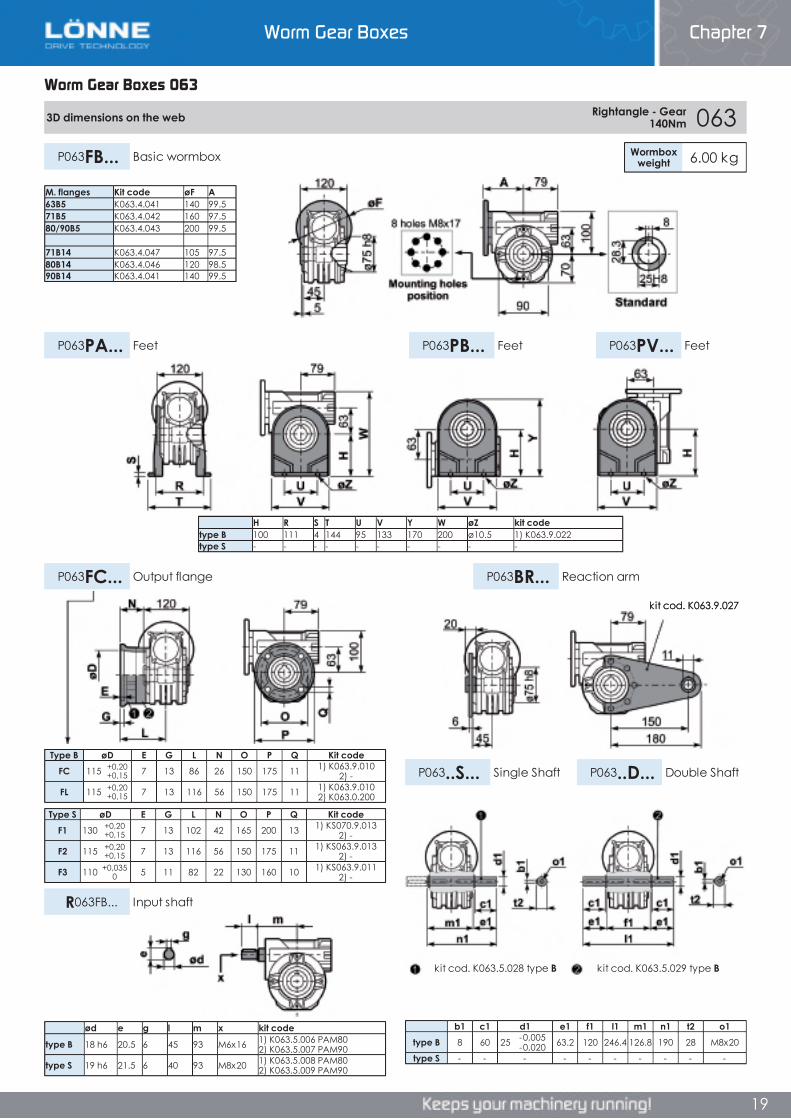
Worm Gear Boxes 063
M. flanges Kit code øF A63B5 K063.4.041 140 99.571B5 K063.4.042 160 97.580/90B5 K063.4.043 200 99.5
71B14 K063.4.047 105 97.580B14 K063.4.046 120 98.590B14 K063.4.041 140 99.5
H R S T U V Y W øZ kit codetype B 100 111 4 144 95 133 170 200 ø10.5 1) K063.9.022type S - - - - - - - - - -
ød e g l m x kit code
type B 18 h6 20.5 6 45 93 M6x16 1) K063.5.006 PAM80 2) K063.5.007 PAM90
type S 19 h6 21.5 6 40 93 M8x20 1) K063.5.008 PAM80 2) K063.5.009 PAM90
3D dimensions on the web Rightangle - Gear 140Nm 063
Wormboxweight 6.00 kgP063FB... Basic wormbox
P063PB... FeetP063PA... Feet P063PV... Feet
P063FC... Output flange P063BR... Reaction arm
P063..S... Single Shaft P063..D... Double Shaft
R063FB... Input shaft
Type B øD E G L N O P Q Kit codeFC 115 +0,20
+0,15 7 13 86 26 150 175 11 1) K063.9.010 2) -
FL 115 +0,20+0,15 7 13 116 56 150 175 11 1) K063.9.010
2) K063.0.200
Type S øD E G L N O P Q Kit codeF1 130 +0,20
+0,15 7 13 102 42 165 200 13 1) KS070.9.013 2) -
F2 115 +0,20+0,15 7 13 116 56 150 175 11 1) KS063.9.013
2) -
F3 110 +0,0350 5 11 82 22 130 160 10 1) KS063.9.011
2) -
b1 c1 d1 e1 f1 l1 m1 n1 t2 o1type B 8 60 25 -0,005
-0,020 63.2 120 246.4 126.8 190 28 M8x20
type S - - - - - - - - - -
kit cod. K063.5.029 type Bkit cod. K063.5.028 type B
kit cod. K063.9.027
Worm Gear Boxes 063
Chapter 7Worm Gear Boxes
Worm Gear Boxes 063
M. flanges Kit code øF A63B5 K063.4.041 140 99.571B5 K063.4.042 160 97.580/90B5 K063.4.043 200 99.5
71B14 K063.4.047 105 97.580B14 K063.4.046 120 98.590B14 K063.4.041 140 99.5
H R S T U V Y W øZ kit codetype B 100 111 4 144 95 133 170 200 ø10.5 1) K063.9.022type S - - - - - - - - - -
ød e g l m x kit code
type B 18 h6 20.5 6 45 93 M6x16 1) K063.5.006 PAM80 2) K063.5.007 PAM90
type S 19 h6 21.5 6 40 93 M8x20 1) K063.5.008 PAM80 2) K063.5.009 PAM90
3D dimensions on the web Rightangle - Gear 140Nm 063
Wormboxweight 6.00 kgP063FB... Basic wormbox
P063PB... FeetP063PA... Feet P063PV... Feet
P063FC... Output flange P063BR... Reaction arm
P063..S... Single Shaft P063..D... Double Shaft
R063FB... Input shaft
Type B øD E G L N O P Q Kit codeFC 115 +0,20
+0,15 7 13 86 26 150 175 11 1) K063.9.010 2) -
FL 115 +0,20+0,15 7 13 116 56 150 175 11 1) K063.9.010
2) K063.0.200
Type S øD E G L N O P Q Kit codeF1 130 +0,20
+0,15 7 13 102 42 165 200 13 1) KS070.9.013 2) -
F2 115 +0,20+0,15 7 13 116 56 150 175 11 1) KS063.9.013
2) -
F3 110 +0,0350 5 11 82 22 130 160 10 1) KS063.9.011
2) -
b1 c1 d1 e1 f1 l1 m1 n1 t2 o1type B 8 60 25 -0,005
-0,020 63.2 120 246.4 126.8 190 28 M8x20
type S - - - - - - - - - -
kit cod. K063.5.029 type Bkit cod. K063.5.028 type B
kit cod. K063.9.027
19
M. flanges Kit code øF A63B5 K063.4.041 140 99.571B5 K063.4.042 160 97.580/90B5 K063.4.043 200 99.5
71B14 K063.4.047 105 97.580B14 K063.4.046 120 98.590B14 K063.4.041 140 99.5
H R S T U V Y W øZ kit codetype B 100 111 4 144 95 133 170 200 ø10.5 1) K063.9.022type S - - - - - - - - - -
ød e g l m x kit code
type B 18 h6 20.5 6 45 93 M6x16 1) K063.5.006 PAM80 2) K063.5.007 PAM90
type S 19 h6 21.5 6 40 93 M8x20 1) K063.5.008 PAM80 2) K063.5.009 PAM90
3D dimensions on the web Rightangle - Gear 140Nm 063
Wormboxweight 6.00 kgP063FB... Basic wormbox
P063PB... FeetP063PA... Feet P063PV... Feet
P063FC... Output flange P063BR... Reaction arm
P063..S... Single Shaft P063..D... Double Shaft
R063FB... Input shaft
Type B øD E G L N O P Q Kit codeFC 115 +0,20
+0,15 7 13 86 26 150 175 11 1) K063.9.010 2) -
FL 115 +0,20+0,15 7 13 116 56 150 175 11 1) K063.9.010
2) K063.0.200
Type S øD E G L N O P Q Kit codeF1 130 +0,20
+0,15 7 13 102 42 165 200 13 1) KS070.9.013 2) -
F2 115 +0,20+0,15 7 13 116 56 150 175 11 1) KS063.9.013
2) -
F3 110 +0,0350 5 11 82 22 130 160 10 1) KS063.9.011
2) -
b1 c1 d1 e1 f1 l1 m1 n1 t2 o1type B 8 60 25 -0,005
-0,020 63.2 120 246.4 126.8 190 28 M8x20
type S - - - - - - - - - -
kit cod. K063.5.029 type Bkit cod. K063.5.028 type B
kit cod. K063.9.027
Worm Gear Boxes Chapter 7
19
Worm Gear Boxes Chapter 7
20
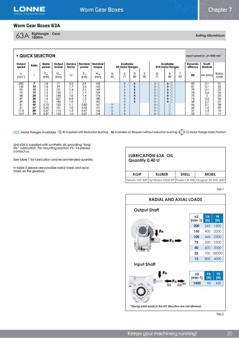
Worm Gear Boxes 63A
63A Rightangle - Gear 180Nm Rating Alluminium
RADIAL AND AXIAL LOADS
AGIP KLUBER SHELL MOBILTelium VSF 320 Syntheso D220 EP Tivela Oil WB Glygoyl 30 SHC 630
n2[min-1]
FA[N]
FR[N]
1400 90 450
n2[min-1]
FA[N]
FR[N]
200 360 1800150 400 2000100 460 230075 500 250050 600 300025 700 3800015 800 4000
• QUICK SELECTION input speed (n 1)=1400 min-1
Outputspeed Ratio Motor
powerOutputtorque
Servicefactor
Nominalpower
Nominaltorque
AvailableB5 motor flanges
AvailableB14 motor flanges
Dynamiceffiency
ToothModule
n2
[min-1] i P1M
[kW]M2M
[Nm] f.s P1R
[kW]M2R
[Nm]B63
C71
D80
E90
Q71
R80
T90 RD Mn [mm] Ratios
code
200 7 1.8 71 2.2 3.9 155 B B B- C B- C 83 3.1 01140 10 1.8 99 1.7 3.0 165 B B B- C B- C 81 3.1 0293 15 1.5 121 1.4 2.1 169 B B B- C B- C 79 3.1 0374 19 1.5 152 1.1 1.7 169 B B B- C B- C 78 2.6 0458 24 1.5 184 1.0 1.4 176 B B B- C B- C 75 2 0547 30 1.5 227 0.8 1.2 180 B B B- C B- C 74 3.2 0639 36 1.1 184 1.0 1.1 181 B B B- C B- C 68 2.7 0731 45 0.75 152 1.1 0.82 167 B B B- C C 66 2.1 0821 67 0.55 151 1.0 0.55 151 B B B- C C 60 1.5 09
17.5 80 0.37 115 1.3 0.47 146 B B B- C C 57 1.3 1014.9 94 0.37 123 1.0 0.37 124 B B B- C C 52 1.1 11
Unit 63A is supplied with synthetic oil, providing “long life” lubrication. For mounting position V5- V6 please contact us.
See table 1 for lubrication and recommended quantity.
In table 2 please see possible radial loads and axial loads on the gearbox.
Output Shaft
Input Shaft
LUBRICATION 63A OIL Quantity 0.40 Lt
Tab 2
Tab 1
*Strong axial loads in the DX direction are not allowed.
B) Supplied with Reduction Bushing B) Available on Request without reduction bushing C) Motor Flange Holes PositionMotor Flanges Available
Worm Gear Boxes 63A
Chapter 7Worm Gear Boxes
20
63A Rightangle - Gear 180Nm Rating Alluminium
RADIAL AND AXIAL LOADS
AGIP KLUBER SHELL MOBILTelium VSF 320 Syntheso D220 EP Tivela Oil WB Glygoyl 30 SHC 630
n2[min-1]
FA[N]
FR[N]
1400 90 450
n2[min-1]
FA[N]
FR[N]
200 360 1800150 400 2000100 460 230075 500 250050 600 300025 700 3800015 800 4000
• QUICK SELECTION input speed (n 1)=1400 min-1
Outputspeed Ratio Motor
powerOutputtorque
Servicefactor
Nominalpower
Nominaltorque
AvailableB5 motor flanges
AvailableB14 motor flanges
Dynamiceffiency
ToothModule
n2
[min-1] i P1M
[kW]M2M
[Nm] f.s P1R
[kW]M2R
[Nm]B63
C71
D80
E90
Q71
R80
T90 RD Mn [mm] Ratios
code
200 7 1.8 71 2.2 3.9 155 B B B- C B- C 83 3.1 01140 10 1.8 99 1.7 3.0 165 B B B- C B- C 81 3.1 0293 15 1.5 121 1.4 2.1 169 B B B- C B- C 79 3.1 0374 19 1.5 152 1.1 1.7 169 B B B- C B- C 78 2.6 0458 24 1.5 184 1.0 1.4 176 B B B- C B- C 75 2 0547 30 1.5 227 0.8 1.2 180 B B B- C B- C 74 3.2 0639 36 1.1 184 1.0 1.1 181 B B B- C B- C 68 2.7 0731 45 0.75 152 1.1 0.82 167 B B B- C C 66 2.1 0821 67 0.55 151 1.0 0.55 151 B B B- C C 60 1.5 09
17.5 80 0.37 115 1.3 0.47 146 B B B- C C 57 1.3 1014.9 94 0.37 123 1.0 0.37 124 B B B- C C 52 1.1 11
Unit 63A is supplied with synthetic oil, providing “long life” lubrication. For mounting position V5- V6 please contact us.
See table 1 for lubrication and recommended quantity.
In table 2 please see possible radial loads and axial loads on the gearbox.
Output Shaft
Input Shaft
LUBRICATION 63A OIL Quantity 0.40 Lt
Tab 2
Tab 1
*Strong axial loads in the DX direction are not allowed.
B) Supplied with Reduction Bushing B) Available on Request without reduction bushing C) Motor Flange Holes PositionMotor Flanges Available
Worm Gear Boxes Chapter 7
20
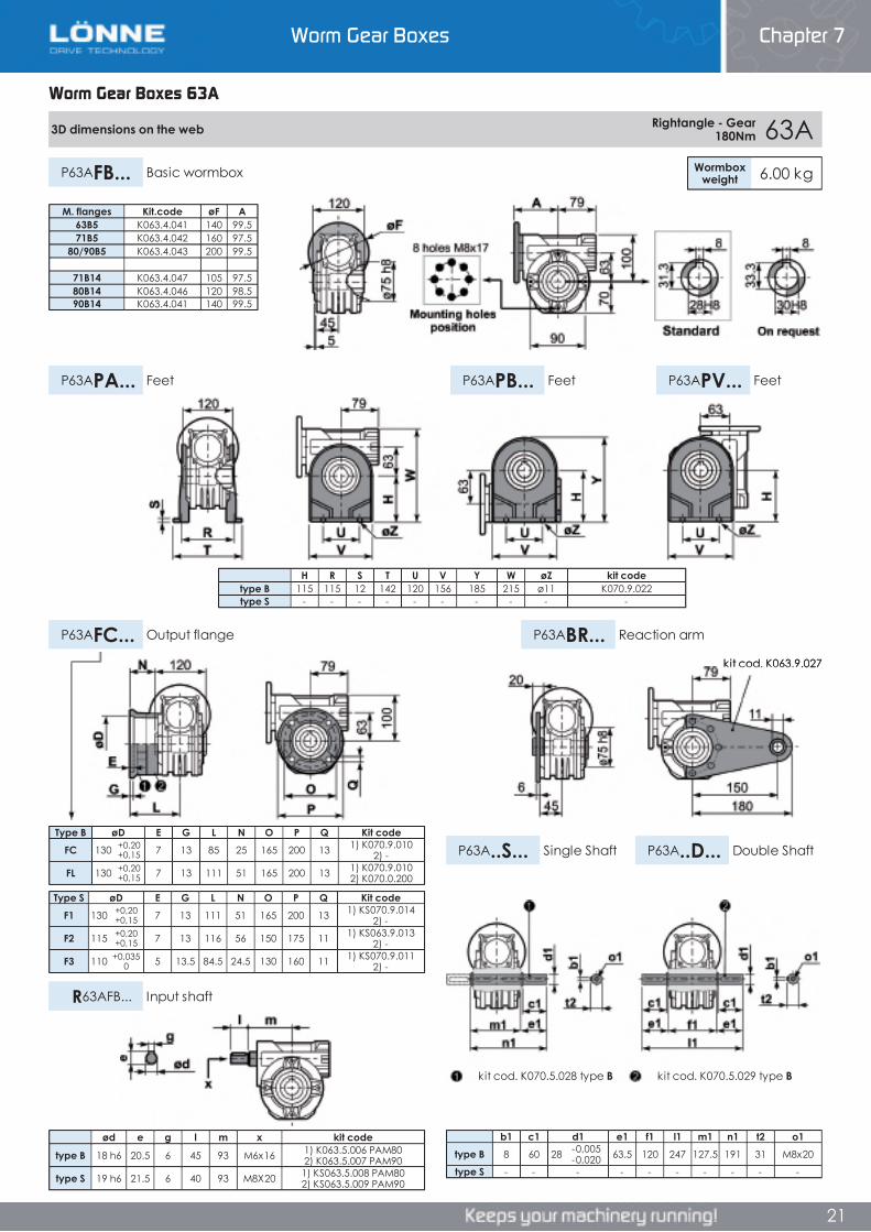
Worm Gear Boxes Chapter 7
21
Worm Gear Boxes 63A
3D dimensions on the web Rightangle - Gear 180Nm 63A
Wormboxweight 6.00 kgP63AFB... Basic wormbox
P63APB... FeetP63APA... Feet P63APV... Feet
P63AFC... Output flange P63ABR... Reaction arm
P63A..S... Single Shaft P63A..D... Double Shaft
R63AFB... Input shaft
Type S øD E G L N O P Q Kit codeF1 130 +0,20
+0,15 7 13 111 51 165 200 13 1) KS070.9.014 2) -
F2 115 +0,20+0,15 7 13 116 56 150 175 11 1) KS063.9.013
2) -
F3 110 +0,0350 5 13.5 84.5 24.5 130 160 11 1) KS070.9.011
2) -
Type B øD E G L N O P Q Kit codeFC 130 +0,20
+0,15 7 13 85 25 165 200 13 1) K070.9.010 2) -
FL 130 +0,20+0,15 7 13 111 51 165 200 13 1) K070.9.010
2) K070.0.200
b1 c1 d1 e1 f1 l1 m1 n1 t2 o1type B 8 60 28 -0,005
-0,020 63.5 120 247 127.5 191 31 M8x20
type S - - - - - - - - - -
M. flanges Kit.code øF A63B5 K063.4.041 140 99.571B5 K063.4.042 160 97.5
80/90B5 K063.4.043 200 99.5
71B14 K063.4.047 105 97.580B14 K063.4.046 120 98.590B14 K063.4.041 140 99.5
H R S T U V Y W øZ kit codetype B 115 115 12 142 120 156 185 215 ø11 K070.9.022type S - - - - - - - - - -
ød e g l m x kit code
type B 18 h6 20.5 6 45 93 M6x16 1) K063.5.006 PAM80 2) K063.5.007 PAM90
type S 19 h6 21.5 6 40 93 M8X20 1) KS063.5.008 PAM80 2) KS063.5.009 PAM90
kit cod. K070.5.028 type B kit cod. K070.5.029 type B
kit cod. K063.9.027
Worm Gear Boxes 63A
Chapter 7Worm Gear Boxes
Worm Gear Boxes 63A
3D dimensions on the web Rightangle - Gear 180Nm 63A
Wormboxweight 6.00 kgP63AFB... Basic wormbox
P63APB... FeetP63APA... Feet P63APV... Feet
P63AFC... Output flange P63ABR... Reaction arm
P63A..S... Single Shaft P63A..D... Double Shaft
R63AFB... Input shaft
Type S øD E G L N O P Q Kit codeF1 130 +0,20
+0,15 7 13 111 51 165 200 13 1) KS070.9.014 2) -
F2 115 +0,20+0,15 7 13 116 56 150 175 11 1) KS063.9.013
2) -
F3 110 +0,0350 5 13.5 84.5 24.5 130 160 11 1) KS070.9.011
2) -
Type B øD E G L N O P Q Kit codeFC 130 +0,20
+0,15 7 13 85 25 165 200 13 1) K070.9.010 2) -
FL 130 +0,20+0,15 7 13 111 51 165 200 13 1) K070.9.010
2) K070.0.200
b1 c1 d1 e1 f1 l1 m1 n1 t2 o1type B 8 60 28 -0,005
-0,020 63.5 120 247 127.5 191 31 M8x20
type S - - - - - - - - - -
M. flanges Kit.code øF A63B5 K063.4.041 140 99.571B5 K063.4.042 160 97.5
80/90B5 K063.4.043 200 99.5
71B14 K063.4.047 105 97.580B14 K063.4.046 120 98.590B14 K063.4.041 140 99.5
H R S T U V Y W øZ kit codetype B 115 115 12 142 120 156 185 215 ø11 K070.9.022type S - - - - - - - - - -
ød e g l m x kit code
type B 18 h6 20.5 6 45 93 M6x16 1) K063.5.006 PAM80 2) K063.5.007 PAM90
type S 19 h6 21.5 6 40 93 M8X20 1) KS063.5.008 PAM80 2) KS063.5.009 PAM90
kit cod. K070.5.028 type B kit cod. K070.5.029 type B
kit cod. K063.9.027
21
3D dimensions on the web Rightangle - Gear 180Nm 63A
Wormboxweight 6.00 kgP63AFB... Basic wormbox
P63APB... FeetP63APA... Feet P63APV... Feet
P63AFC... Output flange P63ABR... Reaction arm
P63A..S... Single Shaft P63A..D... Double Shaft
R63AFB... Input shaft
Type S øD E G L N O P Q Kit codeF1 130 +0,20
+0,15 7 13 111 51 165 200 13 1) KS070.9.014 2) -
F2 115 +0,20+0,15 7 13 116 56 150 175 11 1) KS063.9.013
2) -
F3 110 +0,0350 5 13.5 84.5 24.5 130 160 11 1) KS070.9.011
2) -
Type B øD E G L N O P Q Kit codeFC 130 +0,20
+0,15 7 13 85 25 165 200 13 1) K070.9.010 2) -
FL 130 +0,20+0,15 7 13 111 51 165 200 13 1) K070.9.010
2) K070.0.200
b1 c1 d1 e1 f1 l1 m1 n1 t2 o1type B 8 60 28 -0,005
-0,020 63.5 120 247 127.5 191 31 M8x20
type S - - - - - - - - - -
M. flanges Kit.code øF A63B5 K063.4.041 140 99.571B5 K063.4.042 160 97.5
80/90B5 K063.4.043 200 99.5
71B14 K063.4.047 105 97.580B14 K063.4.046 120 98.590B14 K063.4.041 140 99.5
H R S T U V Y W øZ kit codetype B 115 115 12 142 120 156 185 215 ø11 K070.9.022type S - - - - - - - - - -
ød e g l m x kit code
type B 18 h6 20.5 6 45 93 M6x16 1) K063.5.006 PAM80 2) K063.5.007 PAM90
type S 19 h6 21.5 6 40 93 M8X20 1) KS063.5.008 PAM80 2) KS063.5.009 PAM90
kit cod. K070.5.028 type B kit cod. K070.5.029 type B
kit cod. K063.9.027
Worm Gear Boxes Chapter 7
21
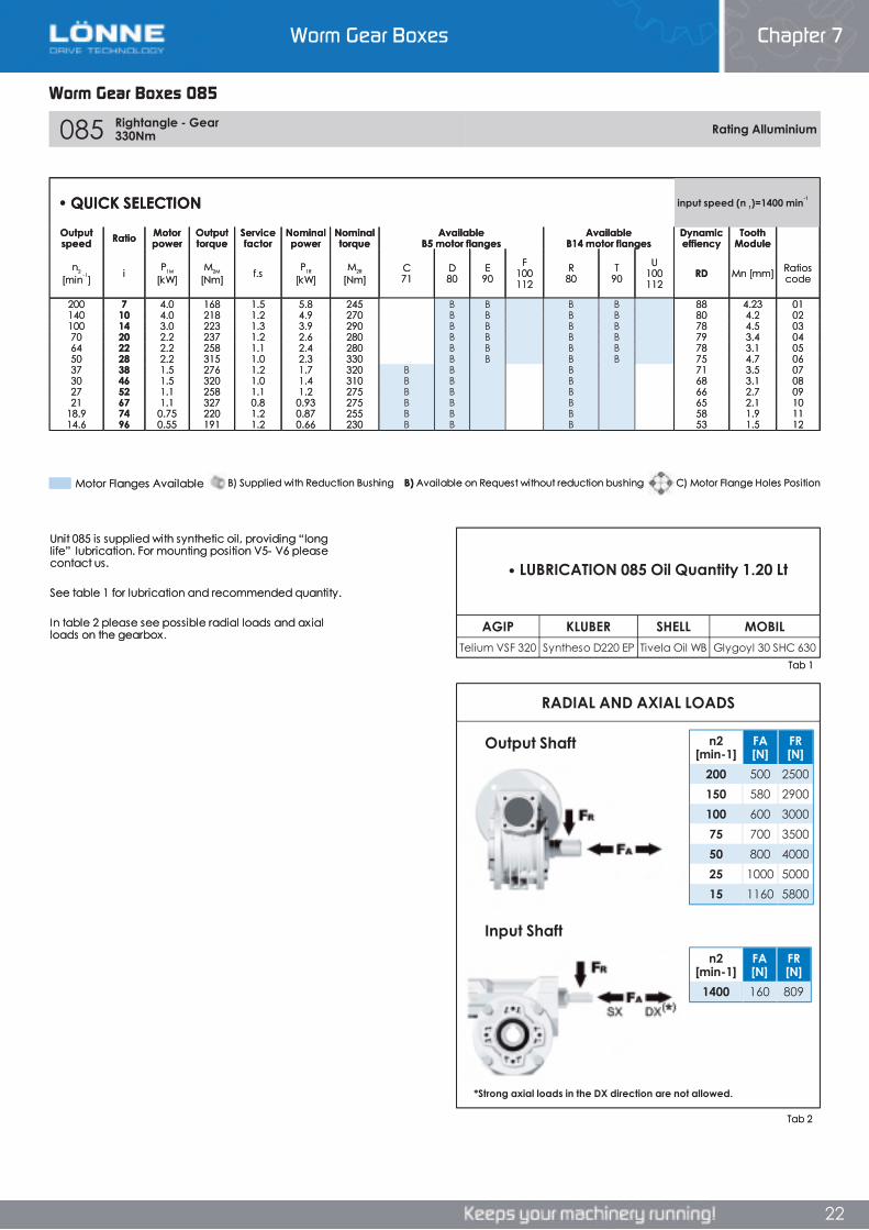
Worm Gear Boxes Chapter 7
22
Worm Gear Boxes 085
085 Rightangle - Gear 330Nm Rating Alluminium
RADIAL AND AXIAL LOADS
AGIP KLUBER SHELL MOBILTelium VSF 320 Syntheso D220 EP Tivela Oil WB Glygoyl 30 SHC 630
n2[min-1]
FA[N]
FR[N]
1400 160 809
n2[min-1]
FA[N]
FR[N]
200 500 2500150 580 2900100 600 300075 700 350050 800 400025 1000 500015 1160 5800
• QUICK SELECTION input speed (n 1)=1400 min-1
Outputspeed Ratio Motor
powerOutputtorque
Servicefactor
Nominalpower
Nominaltorque
AvailableB5 motor flanges
AvailableB14 motor flanges
Dynamiceffiency
ToothModule
n2
[min-1] i P1M
[kW]M2M
[Nm] f.s P1R
[kW]M2R
[Nm]C71
D80
E90
F100112
R80
T90
U100112
RD Mn [mm] Ratioscode
200 7 4.0 168 1.5 5.8 245 B B B B 88 4.23 01140 10 4.0 218 1.2 4.9 270 B B B B 80 4.2 02100 14 3.0 223 1.3 3.9 290 B B B B 78 4.5 0370 20 2.2 237 1.2 2.6 280 B B B B 79 3.4 0464 22 2.2 258 1.1 2.4 280 B B B B 78 3.1 0550 28 2.2 315 1.0 2.3 330 B B B B 75 4.7 0637 38 1.5 276 1.2 1.7 320 B B B 71 3.5 0730 46 1.5 320 1.0 1.4 310 B B B 68 3.1 0827 52 1.1 258 1.1 1.2 275 B B B 66 2.7 0921 67 1.1 327 0.8 0.93 275 B B B 65 2.1 10
18.9 74 0.75 220 1.2 0.87 255 B B B 58 1.9 1114.6 96 0.55 191 1.2 0.66 230 B B B 53 1.5 12
Unit 085 is supplied with synthetic oil, providing “long life” lubrication. For mounting position V5- V6 please contact us.
See table 1 for lubrication and recommended quantity.
In table 2 please see possible radial loads and axial loads on the gearbox.
LUBRICATION 085 Oil Quantity 1.20 Lt
*Strong axial loads in the DX direction are not allowed.
Input Shaft
Tab 1
Output Shaft
Tab 2
Motor Flanges Available C) Motor Flange Holes PositionB) Available on Request without reduction bushingB) Supplied with Reduction Bushing
Worm Gear Boxes 085
Chapter 7Worm Gear Boxes
22
085 Rightangle - Gear 330Nm Rating Alluminium
RADIAL AND AXIAL LOADS
AGIP KLUBER SHELL MOBILTelium VSF 320 Syntheso D220 EP Tivela Oil WB Glygoyl 30 SHC 630
n2[min-1]
FA[N]
FR[N]
1400 160 809
n2[min-1]
FA[N]
FR[N]
200 500 2500150 580 2900100 600 300075 700 350050 800 400025 1000 500015 1160 5800
• QUICK SELECTION input speed (n 1)=1400 min-1
Outputspeed Ratio Motor
powerOutputtorque
Servicefactor
Nominalpower
Nominaltorque
AvailableB5 motor flanges
AvailableB14 motor flanges
Dynamiceffiency
ToothModule
n2
[min-1] i P1M
[kW]M2M
[Nm] f.s P1R
[kW]M2R
[Nm]C71
D80
E90
F100112
R80
T90
U100112
RD Mn [mm] Ratioscode
200 7 4.0 168 1.5 5.8 245 B B B B 88 4.23 01140 10 4.0 218 1.2 4.9 270 B B B B 80 4.2 02100 14 3.0 223 1.3 3.9 290 B B B B 78 4.5 0370 20 2.2 237 1.2 2.6 280 B B B B 79 3.4 0464 22 2.2 258 1.1 2.4 280 B B B B 78 3.1 0550 28 2.2 315 1.0 2.3 330 B B B B 75 4.7 0637 38 1.5 276 1.2 1.7 320 B B B 71 3.5 0730 46 1.5 320 1.0 1.4 310 B B B 68 3.1 0827 52 1.1 258 1.1 1.2 275 B B B 66 2.7 0921 67 1.1 327 0.8 0.93 275 B B B 65 2.1 10
18.9 74 0.75 220 1.2 0.87 255 B B B 58 1.9 1114.6 96 0.55 191 1.2 0.66 230 B B B 53 1.5 12
Unit 085 is supplied with synthetic oil, providing “long life” lubrication. For mounting position V5- V6 please contact us.
See table 1 for lubrication and recommended quantity.
In table 2 please see possible radial loads and axial loads on the gearbox.
LUBRICATION 085 Oil Quantity 1.20 Lt
*Strong axial loads in the DX direction are not allowed.
Input Shaft
Tab 1
Output Shaft
Tab 2
Motor Flanges Available C) Motor Flange Holes PositionB) Available on Request without reduction bushingB) Supplied with Reduction Bushing
Worm Gear Boxes Chapter 7
22
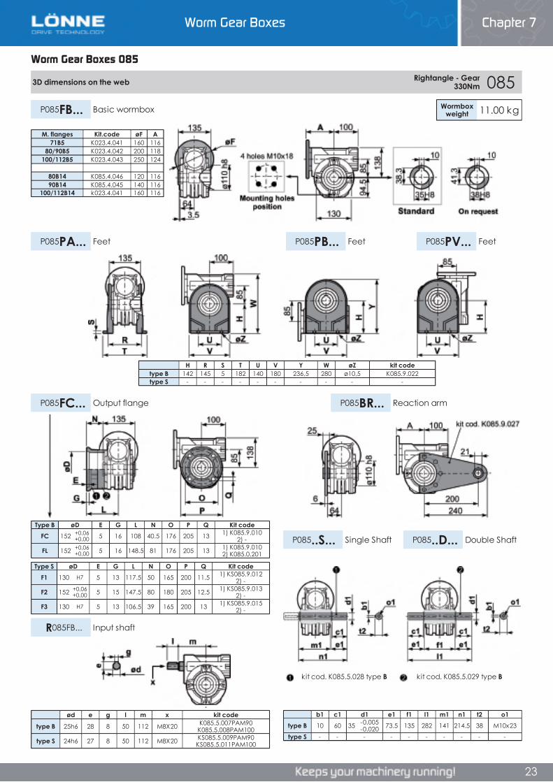
Worm Gear Boxes Chapter 7
23
Worm Gear Boxes 085
3D dimensions on the web Rightangle - Gear 330Nm 085
Wormboxweight 11.00 kgP085FB... Basic wormbox
P085PB... FeetP085PA... Feet P085PV... Feet
P085FC... Output flange P085BR... Reaction arm
P085..S... Single Shaft P085..D... Double Shaft
R085FB... Input shaft
Type B øD E G L N O P Q Kit codeFC 152 +0,06
+0,00 5 16 108 40.5 176 205 13 1) K085.9.010 2) -
FL 152 +0,06+0,00 5 16 148.5 81 176 205 13 1) K085.9.010
2) K085.0.201
Type S øD E G L N O P Q Kit codeF1 130 H7 5 13 117.5 50 165 200 11.5 1) KS085.9.012
2) -
F2 152 +0,06+0,00 5 15 147.5 80 180 205 12.5 1) KS085.9.013
2) -
F3 130 H7 5 13 106.5 39 165 200 13 1) KS085.9.015 2) -
b1 c1 d1 e1 f1 l1 m1 n1 t2 o1type B 10 60 35 -0,005
-0,020 73.5 135 282 141 214.5 38 M10x23
type S - - - - - - - - - -
M. flanges Kit.code øF A71B5 K023.4.041 160 116
80/90B5 K023.4.042 200 118100/112B5 K023.4.043 250 124
80B14 K085.4.046 120 11690B14 K085.4.045 140 116
100/112B14 k023.4.041 160 116
H R S T U V Y W øZ kit codetype B 142 145 5 182 140 180 236,5 280 ø10,5 K085.9.022type S - - - - - - - - - -
ød e g l m x kit code
type B 25h6 28 8 50 112 M8X20 K085.5.007PAM90 K085.5.008PAM100
type S 24h6 27 8 50 112 M8X20 KS085.5.009PAM90 KS085.5.011PAM100
kit cod. K085.5.029 type Bkit cod. K085.5.028 type B
Worm Gear Boxes 085
Chapter 7Worm Gear Boxes
Worm Gear Boxes 085
3D dimensions on the web Rightangle - Gear 330Nm 085
Wormboxweight 11.00 kgP085FB... Basic wormbox
P085PB... FeetP085PA... Feet P085PV... Feet
P085FC... Output flange P085BR... Reaction arm
P085..S... Single Shaft P085..D... Double Shaft
R085FB... Input shaft
Type B øD E G L N O P Q Kit codeFC 152 +0,06
+0,00 5 16 108 40.5 176 205 13 1) K085.9.010 2) -
FL 152 +0,06+0,00 5 16 148.5 81 176 205 13 1) K085.9.010
2) K085.0.201
Type S øD E G L N O P Q Kit codeF1 130 H7 5 13 117.5 50 165 200 11.5 1) KS085.9.012
2) -
F2 152 +0,06+0,00 5 15 147.5 80 180 205 12.5 1) KS085.9.013
2) -
F3 130 H7 5 13 106.5 39 165 200 13 1) KS085.9.015 2) -
b1 c1 d1 e1 f1 l1 m1 n1 t2 o1type B 10 60 35 -0,005
-0,020 73.5 135 282 141 214.5 38 M10x23
type S - - - - - - - - - -
M. flanges Kit.code øF A71B5 K023.4.041 160 116
80/90B5 K023.4.042 200 118100/112B5 K023.4.043 250 124
80B14 K085.4.046 120 11690B14 K085.4.045 140 116
100/112B14 k023.4.041 160 116
H R S T U V Y W øZ kit codetype B 142 145 5 182 140 180 236,5 280 ø10,5 K085.9.022type S - - - - - - - - - -
ød e g l m x kit code
type B 25h6 28 8 50 112 M8X20 K085.5.007PAM90 K085.5.008PAM100
type S 24h6 27 8 50 112 M8X20 KS085.5.009PAM90 KS085.5.011PAM100
kit cod. K085.5.029 type Bkit cod. K085.5.028 type B
23
3D dimensions on the web Rightangle - Gear 330Nm 085
Wormboxweight 11.00 kgP085FB... Basic wormbox
P085PB... FeetP085PA... Feet P085PV... Feet
P085FC... Output flange P085BR... Reaction arm
P085..S... Single Shaft P085..D... Double Shaft
R085FB... Input shaft
Type B øD E G L N O P Q Kit codeFC 152 +0,06
+0,00 5 16 108 40.5 176 205 13 1) K085.9.010 2) -
FL 152 +0,06+0,00 5 16 148.5 81 176 205 13 1) K085.9.010
2) K085.0.201
Type S øD E G L N O P Q Kit codeF1 130 H7 5 13 117.5 50 165 200 11.5 1) KS085.9.012
2) -
F2 152 +0,06+0,00 5 15 147.5 80 180 205 12.5 1) KS085.9.013
2) -
F3 130 H7 5 13 106.5 39 165 200 13 1) KS085.9.015 2) -
b1 c1 d1 e1 f1 l1 m1 n1 t2 o1type B 10 60 35 -0,005
-0,020 73.5 135 282 141 214.5 38 M10x23
type S - - - - - - - - - -
M. flanges Kit.code øF A71B5 K023.4.041 160 116
80/90B5 K023.4.042 200 118100/112B5 K023.4.043 250 124
80B14 K085.4.046 120 11690B14 K085.4.045 140 116
100/112B14 k023.4.041 160 116
H R S T U V Y W øZ kit codetype B 142 145 5 182 140 180 236,5 280 ø10,5 K085.9.022type S - - - - - - - - - -
ød e g l m x kit code
type B 25h6 28 8 50 112 M8X20 K085.5.007PAM90 K085.5.008PAM100
type S 24h6 27 8 50 112 M8X20 KS085.5.009PAM90 KS085.5.011PAM100
kit cod. K085.5.029 type Bkit cod. K085.5.028 type B
Worm Gear Boxes Chapter 7
23
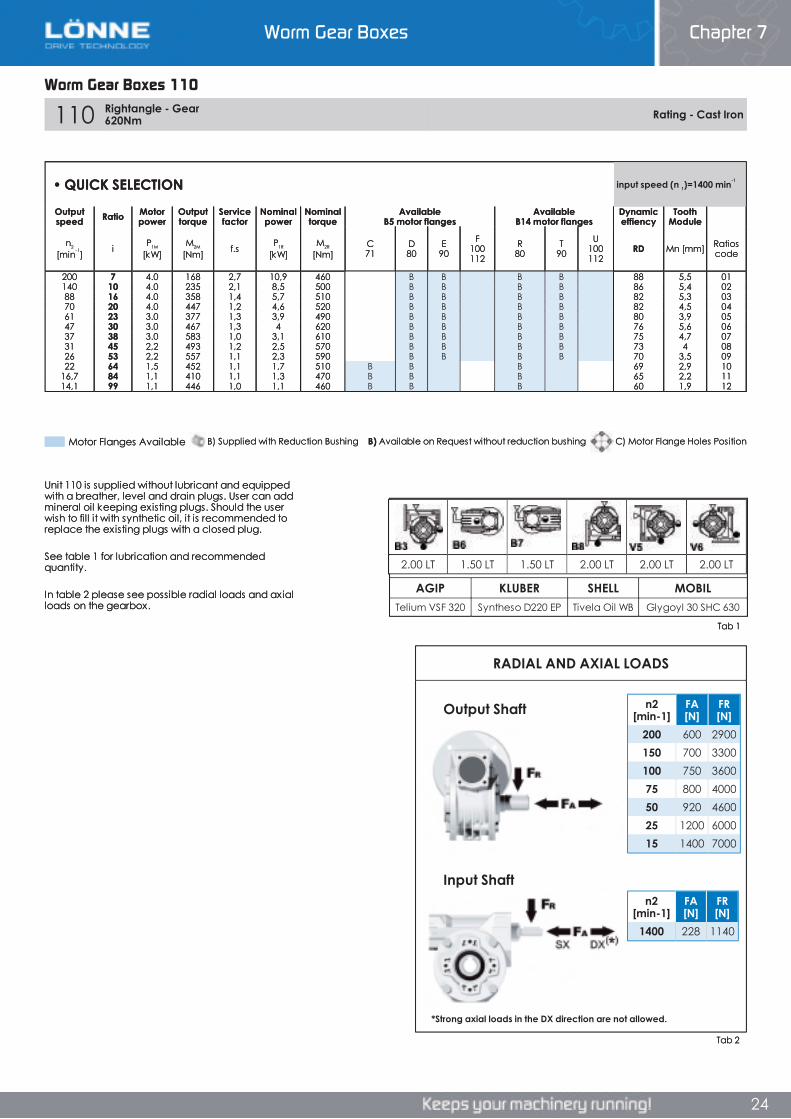
Worm Gear Boxes Chapter 7
24
Worm Gear Boxes 110
110 Rightangle - Gear 620Nm Rating - Cast Iron
AGIP KLUBER SHELL MOBILTelium VSF 320 Syntheso D220 EP Tivela Oil WB Glygoyl 30 SHC 630
RADIAL AND AXIAL LOADS
n2[min-1]
FA[N]
FR[N]
1400 228 1140
n2[min-1]
FA[N]
FR[N]
200 600 2900150 700 3300100 750 360075 800 400050 920 460025 1200 600015 1400 7000
2.00 LT 1.50 LT 1.50 LT 2.00 LT 2.00 LT 2.00 LT
• QUICK SELECTION input speed (n 1)=1400 min-1
Outputspeed Ratio Motor
powerOutputtorque
Servicefactor
Nominalpower
Nominaltorque
AvailableB5 motor flanges
AvailableB14 motor flanges
Dynamiceffiency
ToothModule
n2
[min-1] i P1M
[kW]M2M
[Nm] f.s P1R
[kW]M2R
[Nm]C71
D80
E90
F100112
R80
T90
U100112
RD Mn [mm] Ratioscode
200 7 4.0 168 2,7 10,9 460 B B B B 88 5,5 01140 10 4.0 235 2,1 8,5 500 B B B B 86 5,4 0288 16 4.0 358 1,4 5,7 510 B B B B 82 5,3 0370 20 4.0 447 1,2 4,6 520 B B B B 82 4,5 0461 23 3.0 377 1,3 3,9 490 B B B B 80 3,9 0547 30 3.0 467 1,3 4 620 B B B B 76 5,6 0637 38 3.0 583 1,0 3,1 610 B B B B 75 4,7 0731 45 2,2 493 1,2 2,5 570 B B B B 73 4 0826 53 2,2 557 1,1 2,3 590 B B B B 70 3,5 0922 64 1,5 452 1,1 1,7 510 B B B 69 2,9 10
16,7 84 1,1 410 1,1 1,3 470 B B B 65 2,2 1114,1 99 1,1 446 1,0 1,1 460 B B B 60 1,9 12
Unit 110 is supplied without lubricant and equipped with a breather, level and drain plugs. User can add mineral oil keeping existing plugs. Should the user wish to fill it with synthetic oil, it is recommended to replace the existing plugs with a closed plug.
See table 1 for lubrication and recommended quantity.
In table 2 please see possible radial loads and axial loads on the gearbox.
*Strong axial loads in the DX direction are not allowed.
Input Shaft
Output Shaft
Tab 1
Tab 2
B) Supplied with Reduction Bushing B) Available on Request without reduction bushing C) Motor Flange Holes PositionMotor Flanges Available
Worm Gear Boxes 110
Chapter 7Worm Gear Boxes
Worm Gear Boxes 110
110 Rightangle - Gear 620Nm Rating - Cast Iron
AGIP KLUBER SHELL MOBILTelium VSF 320 Syntheso D220 EP Tivela Oil WB Glygoyl 30 SHC 630
RADIAL AND AXIAL LOADS
n2[min-1]
FA[N]
FR[N]
1400 228 1140
n2[min-1]
FA[N]
FR[N]
200 600 2900150 700 3300100 750 360075 800 400050 920 460025 1200 600015 1400 7000
2.00 LT 1.50 LT 1.50 LT 2.00 LT 2.00 LT 2.00 LT
• QUICK SELECTION input speed (n 1)=1400 min-1
Outputspeed Ratio Motor
powerOutputtorque
Servicefactor
Nominalpower
Nominaltorque
AvailableB5 motor flanges
AvailableB14 motor flanges
Dynamiceffiency
ToothModule
n2
[min-1] i P1M
[kW]M2M
[Nm] f.s P1R
[kW]M2R
[Nm]C71
D80
E90
F100112
R80
T90
U100112
RD Mn [mm] Ratioscode
200 7 4.0 168 2,7 10,9 460 B B B B 88 5,5 01140 10 4.0 235 2,1 8,5 500 B B B B 86 5,4 0288 16 4.0 358 1,4 5,7 510 B B B B 82 5,3 0370 20 4.0 447 1,2 4,6 520 B B B B 82 4,5 0461 23 3.0 377 1,3 3,9 490 B B B B 80 3,9 0547 30 3.0 467 1,3 4 620 B B B B 76 5,6 0637 38 3.0 583 1,0 3,1 610 B B B B 75 4,7 0731 45 2,2 493 1,2 2,5 570 B B B B 73 4 0826 53 2,2 557 1,1 2,3 590 B B B B 70 3,5 0922 64 1,5 452 1,1 1,7 510 B B B 69 2,9 10
16,7 84 1,1 410 1,1 1,3 470 B B B 65 2,2 1114,1 99 1,1 446 1,0 1,1 460 B B B 60 1,9 12
Unit 110 is supplied without lubricant and equipped with a breather, level and drain plugs. User can add mineral oil keeping existing plugs. Should the user wish to fill it with synthetic oil, it is recommended to replace the existing plugs with a closed plug.
See table 1 for lubrication and recommended quantity.
In table 2 please see possible radial loads and axial loads on the gearbox.
*Strong axial loads in the DX direction are not allowed.
Input Shaft
Output Shaft
Tab 1
Tab 2
B) Supplied with Reduction Bushing B) Available on Request without reduction bushing C) Motor Flange Holes PositionMotor Flanges Available
24
Worm Gear Boxes Chapter 7
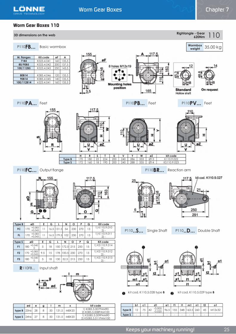
Worm Gear Boxes Chapter 7
25
Worm Gear Boxes 110
3D dimensions on the web Rightangle - Gear 620Nm 110
P110PA... Feet P110PB... Feet
P110FB... Basic wormbox Wormboxweight 35.00 kg
P110PV... Feet
P110FC... Output flange P110BR... Reaction arm
P110..S... Single Shaft P110..D... Double Shaft
R110FB... Input shaft
Type B øD E G L N O P Q Kit codeFC 170 +0,083
+0,043 11 16.5 131.5 54 230 270 13 1) K110.9.010 2) -
FL 170 +0,083+0,043 11 16.5 179.5 102 230 270 13 1) K110.9.011
2) -
Type S øD E G L N O P Q Kit codeF1 180 +0,040
0 5 18 150 172.5 215 250 15 1) KS110.9.014 2) -
F2 170 +0,083+0,043 9.5 15 178 100.5 230 270 13 1) KS110.9.012
2) -
F3 180 +0,0400 5 18 130 52.5 215 250 15 1) KS110.9.013
2) -
b1 c1 d1 e1 f1 l1 m1 n1 t2 o1type B 12 75 42 -0,005
-0,020 96.5 155 348 163.5 260 45 M12x32
type S - - - - - - - - - -
M. flanges Kit.code øF A71B5 K023.4.041 160 135,5
80/90B5 K023.4.042 200 137,5100/112B5 K023.4.043 250 143,5
80B14 K085.4.046 120 135,590B14 K085.4.045 140 135,5
100/112B14 k023.4.041 160 135,5
H R S T U V Y W øZ kit codeType B 170 180 22 224 200 240 286 333 Ø13 K110.9.022Type S 172 160 18 190 200 240 288 335 Ø14 KS110.9.023
ød e g l m x kit code
type B 25h6 28 8 50 131,5 M8X20 1) K085.5.007PAM90 2) K085.5.008PAM100
type S 24h6 27 8 50 131,5 M8X20 1) KS085.5.009PAM90 2) KS085.5.011PAM100
kit cod. K110.5.028 type B kit cod. K110.5.029 type B
Worm Gear Boxes 110
Chapter 7Worm Gear Boxes
Worm Gear Boxes 110
3D dimensions on the web Rightangle - Gear 620Nm 110
P110PA... Feet P110PB... Feet
P110FB... Basic wormbox Wormboxweight 35.00 kg
P110PV... Feet
P110FC... Output flange P110BR... Reaction arm
P110..S... Single Shaft P110..D... Double Shaft
R110FB... Input shaft
Type B øD E G L N O P Q Kit codeFC 170 +0,083
+0,043 11 16.5 131.5 54 230 270 13 1) K110.9.010 2) -
FL 170 +0,083+0,043 11 16.5 179.5 102 230 270 13 1) K110.9.011
2) -
Type S øD E G L N O P Q Kit codeF1 180 +0,040
0 5 18 150 172.5 215 250 15 1) KS110.9.014 2) -
F2 170 +0,083+0,043 9.5 15 178 100.5 230 270 13 1) KS110.9.012
2) -
F3 180 +0,0400 5 18 130 52.5 215 250 15 1) KS110.9.013
2) -
b1 c1 d1 e1 f1 l1 m1 n1 t2 o1type B 12 75 42 -0,005
-0,020 96.5 155 348 163.5 260 45 M12x32
type S - - - - - - - - - -
M. flanges Kit.code øF A71B5 K023.4.041 160 135,5
80/90B5 K023.4.042 200 137,5100/112B5 K023.4.043 250 143,5
80B14 K085.4.046 120 135,590B14 K085.4.045 140 135,5
100/112B14 k023.4.041 160 135,5
H R S T U V Y W øZ kit codeType B 170 180 22 224 200 240 286 333 Ø13 K110.9.022Type S 172 160 18 190 200 240 288 335 Ø14 KS110.9.023
ød e g l m x kit code
type B 25h6 28 8 50 131,5 M8X20 1) K085.5.007PAM90 2) K085.5.008PAM100
type S 24h6 27 8 50 131,5 M8X20 1) KS085.5.009PAM90 2) KS085.5.011PAM100
kit cod. K110.5.028 type B kit cod. K110.5.029 type B
25
3D dimensions on the web Rightangle - Gear 620Nm 110
P110PA... Feet P110PB... Feet
P110FB... Basic wormbox Wormboxweight 35.00 kg
P110PV... Feet
P110FC... Output flange P110BR... Reaction arm
P110..S... Single Shaft P110..D... Double Shaft
R110FB... Input shaft
Type B øD E G L N O P Q Kit codeFC 170 +0,083
+0,043 11 16.5 131.5 54 230 270 13 1) K110.9.010 2) -
FL 170 +0,083+0,043 11 16.5 179.5 102 230 270 13 1) K110.9.011
2) -
Type S øD E G L N O P Q Kit codeF1 180 +0,040
0 5 18 150 172.5 215 250 15 1) KS110.9.014 2) -
F2 170 +0,083+0,043 9.5 15 178 100.5 230 270 13 1) KS110.9.012
2) -
F3 180 +0,0400 5 18 130 52.5 215 250 15 1) KS110.9.013
2) -
b1 c1 d1 e1 f1 l1 m1 n1 t2 o1type B 12 75 42 -0,005
-0,020 96.5 155 348 163.5 260 45 M12x32
type S - - - - - - - - - -
M. flanges Kit.code øF A71B5 K023.4.041 160 135,5
80/90B5 K023.4.042 200 137,5100/112B5 K023.4.043 250 143,5
80B14 K085.4.046 120 135,590B14 K085.4.045 140 135,5
100/112B14 k023.4.041 160 135,5
H R S T U V Y W øZ kit codeType B 170 180 22 224 200 240 286 333 Ø13 K110.9.022Type S 172 160 18 190 200 240 288 335 Ø14 KS110.9.023
ød e g l m x kit code
type B 25h6 28 8 50 131,5 M8X20 1) K085.5.007PAM90 2) K085.5.008PAM100
type S 24h6 27 8 50 131,5 M8X20 1) KS085.5.009PAM90 2) KS085.5.011PAM100
kit cod. K110.5.028 type B kit cod. K110.5.029 type B
Worm Gear Boxes Chapter 7
25
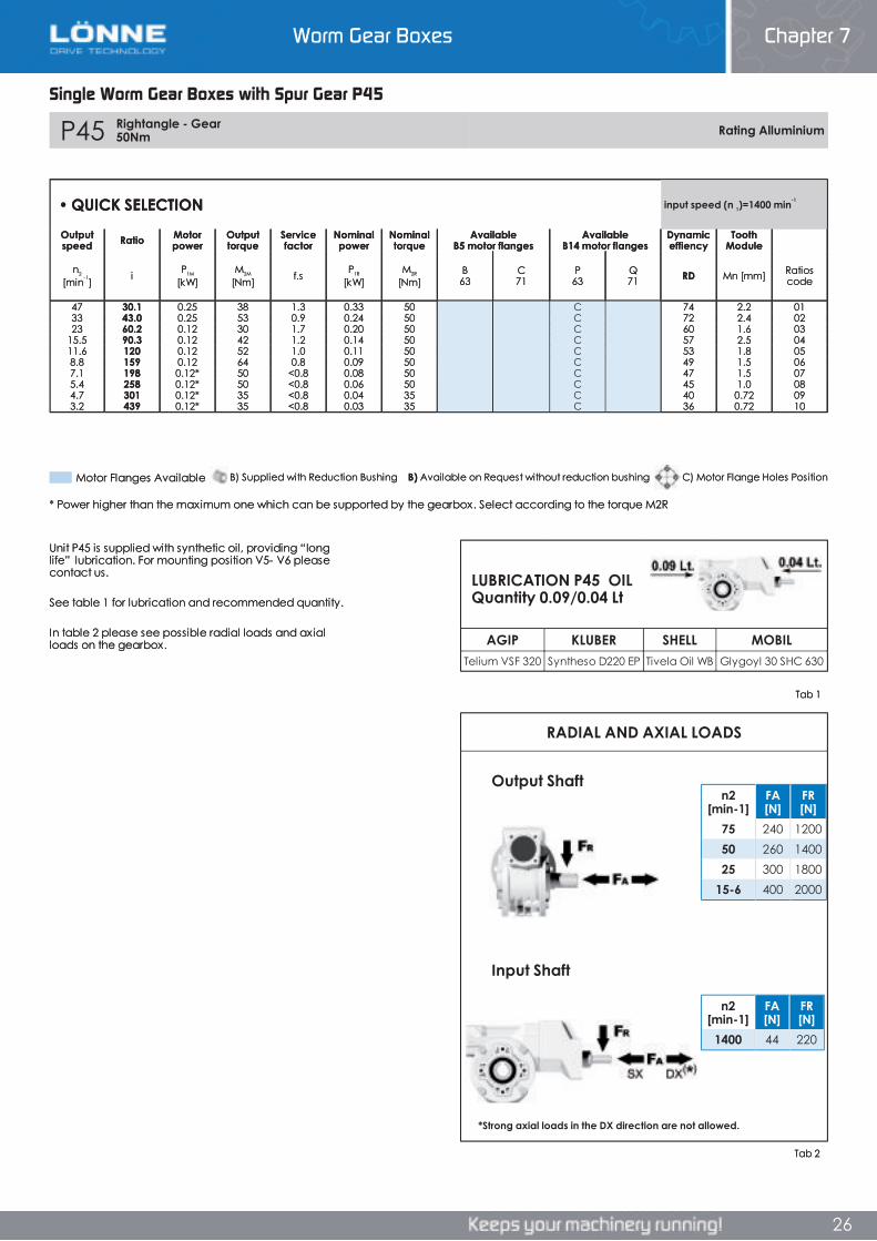
Worm Gear Boxes Chapter 7
26
Single Worm Gear Boxes with Spur Gear P45
P45 Rightangle - Gear 50Nm Rating Alluminium
RADIAL AND AXIAL LOADS
AGIP KLUBER SHELL MOBILTelium VSF 320 Syntheso D220 EP Tivela Oil WB Glygoyl 30 SHC 630
n2[min-1]
FA[N]
FR[N]
1400 44 220
n2[min-1]
FA[N]
FR[N]
75 240 120050 260 140025 300 1800
15-6 400 2000
• QUICK SELECTION input speed (n 1)=1400 min-1
Outputspeed Ratio Motor
powerOutputtorque
Servicefactor
Nominalpower
Nominaltorque
AvailableB5 motor flanges
AvailableB14 motor flanges
Dynamiceffiency
ToothModule
n2
[min-1] i P1M
[kW]M2M
[Nm] f.s P1R
[kW]M2R
[Nm]B63
C71
P63
Q71 RD Mn [mm] Ratios
code
47 30.1 0.25 38 1.3 0.33 50 C 74 2.2 0133 43.0 0.25 53 0.9 0.24 50 C 72 2.4 0223 60.2 0.12 30 1.7 0.20 50 C 60 1.6 03
15.5 90.3 0.12 42 1.2 0.14 50 C 57 2.5 0411.6 120 0.12 52 1.0 0.11 50 C 53 1.8 058.8 159 0.12 64 0.8 0.09 50 C 49 1.5 067.1 198 0.12* 50 <0.8 0.08 50 C 47 1.5 075.4 258 0.12* 50 <0.8 0.06 50 C 45 1.0 084.7 301 0.12* 35 <0.8 0.04 35 C 40 0.72 093.2 439 0.12* 35 <0.8 0.03 35 C 36 0.72 10
Unit P45 is supplied with synthetic oil, providing “long life” lubrication. For mounting position V5- V6 please contact us.
See table 1 for lubrication and recommended quantity.
In table 2 please see possible radial loads and axial loads on the gearbox.
LUBRICATION P45 OIL Quantity 0.09/0.04 Lt
*Strong axial loads in the DX direction are not allowed.
Output Shaft
Input Shaft
Tab 1
Tab 2
* Power higher than the maximum one which can be supported by the gearbox. Select according to the torque M2R
Motor Flanges Available C) Motor Flange Holes PositionB) Available on Request without reduction bushingB) Supplied with Reduction Bushing
Single Worm Gear Boxes with Spur Gear P45
Chapter 7Worm Gear Boxes
Single Worm Gear Boxes with Spur Gear P45
P45 Rightangle - Gear 50Nm Rating Alluminium
RADIAL AND AXIAL LOADS
AGIP KLUBER SHELL MOBILTelium VSF 320 Syntheso D220 EP Tivela Oil WB Glygoyl 30 SHC 630
n2[min-1]
FA[N]
FR[N]
1400 44 220
n2[min-1]
FA[N]
FR[N]
75 240 120050 260 140025 300 1800
15-6 400 2000
• QUICK SELECTION input speed (n 1)=1400 min-1
Outputspeed Ratio Motor
powerOutputtorque
Servicefactor
Nominalpower
Nominaltorque
AvailableB5 motor flanges
AvailableB14 motor flanges
Dynamiceffiency
ToothModule
n2
[min-1] i P1M
[kW]M2M
[Nm] f.s P1R
[kW]M2R
[Nm]B63
C71
P63
Q71 RD Mn [mm] Ratios
code
47 30.1 0.25 38 1.3 0.33 50 C 74 2.2 0133 43.0 0.25 53 0.9 0.24 50 C 72 2.4 0223 60.2 0.12 30 1.7 0.20 50 C 60 1.6 03
15.5 90.3 0.12 42 1.2 0.14 50 C 57 2.5 0411.6 120 0.12 52 1.0 0.11 50 C 53 1.8 058.8 159 0.12 64 0.8 0.09 50 C 49 1.5 067.1 198 0.12* 50 <0.8 0.08 50 C 47 1.5 075.4 258 0.12* 50 <0.8 0.06 50 C 45 1.0 084.7 301 0.12* 35 <0.8 0.04 35 C 40 0.72 093.2 439 0.12* 35 <0.8 0.03 35 C 36 0.72 10
Unit P45 is supplied with synthetic oil, providing “long life” lubrication. For mounting position V5- V6 please contact us.
See table 1 for lubrication and recommended quantity.
In table 2 please see possible radial loads and axial loads on the gearbox.
LUBRICATION P45 OIL Quantity 0.09/0.04 Lt
*Strong axial loads in the DX direction are not allowed.
Output Shaft
Input Shaft
Tab 1
Tab 2
* Power higher than the maximum one which can be supported by the gearbox. Select according to the torque M2R
Motor Flanges Available C) Motor Flange Holes PositionB) Available on Request without reduction bushingB) Supplied with Reduction Bushing
26
P45 Rightangle - Gear 50Nm Rating Alluminium
RADIAL AND AXIAL LOADS
AGIP KLUBER SHELL MOBILTelium VSF 320 Syntheso D220 EP Tivela Oil WB Glygoyl 30 SHC 630
n2[min-1]
FA[N]
FR[N]
1400 44 220
n2[min-1]
FA[N]
FR[N]
75 240 120050 260 140025 300 1800
15-6 400 2000
• QUICK SELECTION input speed (n 1)=1400 min-1
Outputspeed Ratio Motor
powerOutputtorque
Servicefactor
Nominalpower
Nominaltorque
AvailableB5 motor flanges
AvailableB14 motor flanges
Dynamiceffiency
ToothModule
n2
[min-1] i P1M
[kW]M2M
[Nm] f.s P1R
[kW]M2R
[Nm]B63
C71
P63
Q71 RD Mn [mm] Ratios
code
47 30.1 0.25 38 1.3 0.33 50 C 74 2.2 0133 43.0 0.25 53 0.9 0.24 50 C 72 2.4 0223 60.2 0.12 30 1.7 0.20 50 C 60 1.6 03
15.5 90.3 0.12 42 1.2 0.14 50 C 57 2.5 0411.6 120 0.12 52 1.0 0.11 50 C 53 1.8 058.8 159 0.12 64 0.8 0.09 50 C 49 1.5 067.1 198 0.12* 50 <0.8 0.08 50 C 47 1.5 075.4 258 0.12* 50 <0.8 0.06 50 C 45 1.0 084.7 301 0.12* 35 <0.8 0.04 35 C 40 0.72 093.2 439 0.12* 35 <0.8 0.03 35 C 36 0.72 10
Unit P45 is supplied with synthetic oil, providing “long life” lubrication. For mounting position V5- V6 please contact us.
See table 1 for lubrication and recommended quantity.
In table 2 please see possible radial loads and axial loads on the gearbox.
LUBRICATION P45 OIL Quantity 0.09/0.04 Lt
*Strong axial loads in the DX direction are not allowed.
Output Shaft
Input Shaft
Tab 1
Tab 2
* Power higher than the maximum one which can be supported by the gearbox. Select according to the torque M2R
Motor Flanges Available C) Motor Flange Holes PositionB) Available on Request without reduction bushingB) Supplied with Reduction Bushing
Worm Gear Boxes Chapter 7
26
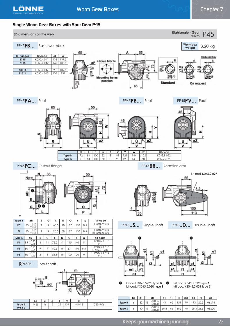
Worm Gear Boxes Chapter 7
26
Single Worm Gear Boxes with Spur Gear P45
P45 Rightangle - Gear 50Nm Rating Alluminium
RADIAL AND AXIAL LOADS
AGIP KLUBER SHELL MOBILTelium VSF 320 Syntheso D220 EP Tivela Oil WB Glygoyl 30 SHC 630
n2[min-1]
FA[N]
FR[N]
1400 44 220
n2[min-1]
FA[N]
FR[N]
75 240 120050 260 140025 300 1800
15-6 400 2000
• QUICK SELECTION input speed (n 1)=1400 min-1
Outputspeed Ratio Motor
powerOutputtorque
Servicefactor
Nominalpower
Nominaltorque
AvailableB5 motor flanges
AvailableB14 motor flanges
Dynamiceffiency
ToothModule
n2
[min-1] i P1M
[kW]M2M
[Nm] f.s P1R
[kW]M2R
[Nm]B63
C71
P63
Q71 RD Mn [mm] Ratios
code
47 30.1 0.25 38 1.3 0.33 50 C 74 2.2 0133 43.0 0.25 53 0.9 0.24 50 C 72 2.4 0223 60.2 0.12 30 1.7 0.20 50 C 60 1.6 03
15.5 90.3 0.12 42 1.2 0.14 50 C 57 2.5 0411.6 120 0.12 52 1.0 0.11 50 C 53 1.8 058.8 159 0.12 64 0.8 0.09 50 C 49 1.5 067.1 198 0.12* 50 <0.8 0.08 50 C 47 1.5 075.4 258 0.12* 50 <0.8 0.06 50 C 45 1.0 084.7 301 0.12* 35 <0.8 0.04 35 C 40 0.72 093.2 439 0.12* 35 <0.8 0.03 35 C 36 0.72 10
Unit P45 is supplied with synthetic oil, providing “long life” lubrication. For mounting position V5- V6 please contact us.
See table 1 for lubrication and recommended quantity.
In table 2 please see possible radial loads and axial loads on the gearbox.
LUBRICATION P45 OIL Quantity 0.09/0.04 Lt
*Strong axial loads in the DX direction are not allowed.
Output Shaft
Input Shaft
Tab 1
Tab 2
* Power higher than the maximum one which can be supported by the gearbox. Select according to the torque M2R
Motor Flanges Available C) Motor Flange Holes PositionB) Available on Request without reduction bushingB) Supplied with Reduction Bushing
Single Worm Gear Boxes with Spur Gear P45
Chapter 7Worm Gear Boxes
Single Worm Gear Boxes with Spur Gear P45
P45 Rightangle - Gear 50Nm Rating Alluminium
RADIAL AND AXIAL LOADS
AGIP KLUBER SHELL MOBILTelium VSF 320 Syntheso D220 EP Tivela Oil WB Glygoyl 30 SHC 630
n2[min-1]
FA[N]
FR[N]
1400 44 220
n2[min-1]
FA[N]
FR[N]
75 240 120050 260 140025 300 1800
15-6 400 2000
• QUICK SELECTION input speed (n 1)=1400 min-1
Outputspeed Ratio Motor
powerOutputtorque
Servicefactor
Nominalpower
Nominaltorque
AvailableB5 motor flanges
AvailableB14 motor flanges
Dynamiceffiency
ToothModule
n2
[min-1] i P1M
[kW]M2M
[Nm] f.s P1R
[kW]M2R
[Nm]B63
C71
P63
Q71 RD Mn [mm] Ratios
code
47 30.1 0.25 38 1.3 0.33 50 C 74 2.2 0133 43.0 0.25 53 0.9 0.24 50 C 72 2.4 0223 60.2 0.12 30 1.7 0.20 50 C 60 1.6 03
15.5 90.3 0.12 42 1.2 0.14 50 C 57 2.5 0411.6 120 0.12 52 1.0 0.11 50 C 53 1.8 058.8 159 0.12 64 0.8 0.09 50 C 49 1.5 067.1 198 0.12* 50 <0.8 0.08 50 C 47 1.5 075.4 258 0.12* 50 <0.8 0.06 50 C 45 1.0 084.7 301 0.12* 35 <0.8 0.04 35 C 40 0.72 093.2 439 0.12* 35 <0.8 0.03 35 C 36 0.72 10
Unit P45 is supplied with synthetic oil, providing “long life” lubrication. For mounting position V5- V6 please contact us.
See table 1 for lubrication and recommended quantity.
In table 2 please see possible radial loads and axial loads on the gearbox.
LUBRICATION P45 OIL Quantity 0.09/0.04 Lt
*Strong axial loads in the DX direction are not allowed.
Output Shaft
Input Shaft
Tab 1
Tab 2
* Power higher than the maximum one which can be supported by the gearbox. Select according to the torque M2R
Motor Flanges Available C) Motor Flange Holes PositionB) Available on Request without reduction bushingB) Supplied with Reduction Bushing
26
P45 Rightangle - Gear 50Nm Rating Alluminium
RADIAL AND AXIAL LOADS
AGIP KLUBER SHELL MOBILTelium VSF 320 Syntheso D220 EP Tivela Oil WB Glygoyl 30 SHC 630
n2[min-1]
FA[N]
FR[N]
1400 44 220
n2[min-1]
FA[N]
FR[N]
75 240 120050 260 140025 300 1800
15-6 400 2000
• QUICK SELECTION input speed (n 1)=1400 min-1
Outputspeed Ratio Motor
powerOutputtorque
Servicefactor
Nominalpower
Nominaltorque
AvailableB5 motor flanges
AvailableB14 motor flanges
Dynamiceffiency
ToothModule
n2
[min-1] i P1M
[kW]M2M
[Nm] f.s P1R
[kW]M2R
[Nm]B63
C71
P63
Q71 RD Mn [mm] Ratios
code
47 30.1 0.25 38 1.3 0.33 50 C 74 2.2 0133 43.0 0.25 53 0.9 0.24 50 C 72 2.4 0223 60.2 0.12 30 1.7 0.20 50 C 60 1.6 03
15.5 90.3 0.12 42 1.2 0.14 50 C 57 2.5 0411.6 120 0.12 52 1.0 0.11 50 C 53 1.8 058.8 159 0.12 64 0.8 0.09 50 C 49 1.5 067.1 198 0.12* 50 <0.8 0.08 50 C 47 1.5 075.4 258 0.12* 50 <0.8 0.06 50 C 45 1.0 084.7 301 0.12* 35 <0.8 0.04 35 C 40 0.72 093.2 439 0.12* 35 <0.8 0.03 35 C 36 0.72 10
Unit P45 is supplied with synthetic oil, providing “long life” lubrication. For mounting position V5- V6 please contact us.
See table 1 for lubrication and recommended quantity.
In table 2 please see possible radial loads and axial loads on the gearbox.
LUBRICATION P45 OIL Quantity 0.09/0.04 Lt
*Strong axial loads in the DX direction are not allowed.
Output Shaft
Input Shaft
Tab 1
Tab 2
* Power higher than the maximum one which can be supported by the gearbox. Select according to the torque M2R
Motor Flanges Available C) Motor Flange Holes PositionB) Available on Request without reduction bushingB) Supplied with Reduction Bushing
Worm Gear Boxes Chapter 7
26
Worm Gear Boxes Chapter 7
27
Single Worm Gear Boxes with Spur Gear P45
3D dimensions on the web Rightangle - Gear 50Nm P45
Wormboxweight 3.20 kgPP45FB... Basic wormbox
PP45PB... FeetPP45PA... Feet PP45PV... Feet
PP45FC... Output flange PP45BR... Reaction arm
PP45..S... Single Shaft PP45..D... Double Shaft
RP45FB... Input shaft
Type B øD E G L N O P Q Kit codeFC 60 +0,15
+0,05 9 9 60.5 28 87 110 8.5 1) K045.9.010 2) -
FL 60 +0,15+0,05 9 9 90.5 58 87 110 8.5 1) K045.9.010
2) K045.0.200
Type S øD E G L N O P Q Kit codeF1 95 +0,20
+0,15 4 11 73.5 41 115 140 9 1) KS045.9.013 2) -
F2 60 +0,15+0,05 9 9 60.5 19 87 110 8.5 1) KS045.9.010
3) S045.0.204
F3 80 +0,03+0,00 3 8 51.5 19 100 120 9 1) KS045.9.014
2) -
b1 c1 d1 e1 f1 l1 m1 n1 t2 o1type B 6 32 18 -0,005
-0,020 43 65 151 70 113 20.5 M6x18
type S 6 40 19 -0,005-0,020 58.8 65 182 70 128.5 21.5 M8x20
H R t u S V Y W øZ Kit codeType B 72 81 100 52 3 98 121 144 ø10.5 K045.9.022Type S 71 84 100 70 8 90 120 143 ø8 KS045.9.023
M. flanges Kit.code øF A63B5 K050.4.041 138 137.571B5 K050.4.042 160 135.5
63B14 K050.4.047 90 139.571B14 K050.4.045 105 137
ød e g l m xtype B 14 j6 16 5 25 131 M5x13 C35.5.061type S - - - - - -
kit cod. K045.5.029 type Bkit cod. KS045.5.031 type S
kit cod. K045.5.028 type Bkit cod. KS045.5.030 type S
kit cod. K045.9.027
Single Worm Gear Boxes with Spur Gear P45
Chapter 7Worm Gear Boxes
Single Worm Gear Boxes with Spur Gear P45
3D dimensions on the web Rightangle - Gear 50Nm P45
Wormboxweight 3.20 kgPP45FB... Basic wormbox
PP45PB... FeetPP45PA... Feet PP45PV... Feet
PP45FC... Output flange PP45BR... Reaction arm
PP45..S... Single Shaft PP45..D... Double Shaft
RP45FB... Input shaft
Type B øD E G L N O P Q Kit codeFC 60 +0,15
+0,05 9 9 60.5 28 87 110 8.5 1) K045.9.010 2) -
FL 60 +0,15+0,05 9 9 90.5 58 87 110 8.5 1) K045.9.010
2) K045.0.200
Type S øD E G L N O P Q Kit codeF1 95 +0,20
+0,15 4 11 73.5 41 115 140 9 1) KS045.9.013 2) -
F2 60 +0,15+0,05 9 9 60.5 19 87 110 8.5 1) KS045.9.010
3) S045.0.204
F3 80 +0,03+0,00 3 8 51.5 19 100 120 9 1) KS045.9.014
2) -
b1 c1 d1 e1 f1 l1 m1 n1 t2 o1type B 6 32 18 -0,005
-0,020 43 65 151 70 113 20.5 M6x18
type S 6 40 19 -0,005-0,020 58.8 65 182 70 128.5 21.5 M8x20
H R t u S V Y W øZ Kit codeType B 72 81 100 52 3 98 121 144 ø10.5 K045.9.022Type S 71 84 100 70 8 90 120 143 ø8 KS045.9.023
M. flanges Kit.code øF A63B5 K050.4.041 138 137.571B5 K050.4.042 160 135.5
63B14 K050.4.047 90 139.571B14 K050.4.045 105 137
ød e g l m xtype B 14 j6 16 5 25 131 M5x13 C35.5.061type S - - - - - -
kit cod. K045.5.029 type Bkit cod. KS045.5.031 type S
kit cod. K045.5.028 type Bkit cod. KS045.5.030 type S
kit cod. K045.9.027
27
3D dimensions on the web Rightangle - Gear 50Nm P45
Wormboxweight 3.20 kgPP45FB... Basic wormbox
PP45PB... FeetPP45PA... Feet PP45PV... Feet
PP45FC... Output flange PP45BR... Reaction arm
PP45..S... Single Shaft PP45..D... Double Shaft
RP45FB... Input shaft
Type B øD E G L N O P Q Kit codeFC 60 +0,15
+0,05 9 9 60.5 28 87 110 8.5 1) K045.9.010 2) -
FL 60 +0,15+0,05 9 9 90.5 58 87 110 8.5 1) K045.9.010
2) K045.0.200
Type S øD E G L N O P Q Kit codeF1 95 +0,20
+0,15 4 11 73.5 41 115 140 9 1) KS045.9.013 2) -
F2 60 +0,15+0,05 9 9 60.5 19 87 110 8.5 1) KS045.9.010
3) S045.0.204
F3 80 +0,03+0,00 3 8 51.5 19 100 120 9 1) KS045.9.014
2) -
b1 c1 d1 e1 f1 l1 m1 n1 t2 o1type B 6 32 18 -0,005
-0,020 43 65 151 70 113 20.5 M6x18
type S 6 40 19 -0,005-0,020 58.8 65 182 70 128.5 21.5 M8x20
H R t u S V Y W øZ Kit codeType B 72 81 100 52 3 98 121 144 ø10.5 K045.9.022Type S 71 84 100 70 8 90 120 143 ø8 KS045.9.023
M. flanges Kit.code øF A63B5 K050.4.041 138 137.571B5 K050.4.042 160 135.5
63B14 K050.4.047 90 139.571B14 K050.4.045 105 137
ød e g l m xtype B 14 j6 16 5 25 131 M5x13 C35.5.061type S - - - - - -
kit cod. K045.5.029 type Bkit cod. KS045.5.031 type S
kit cod. K045.5.028 type Bkit cod. KS045.5.030 type S
kit cod. K045.9.027
Worm Gear Boxes Chapter 7
27
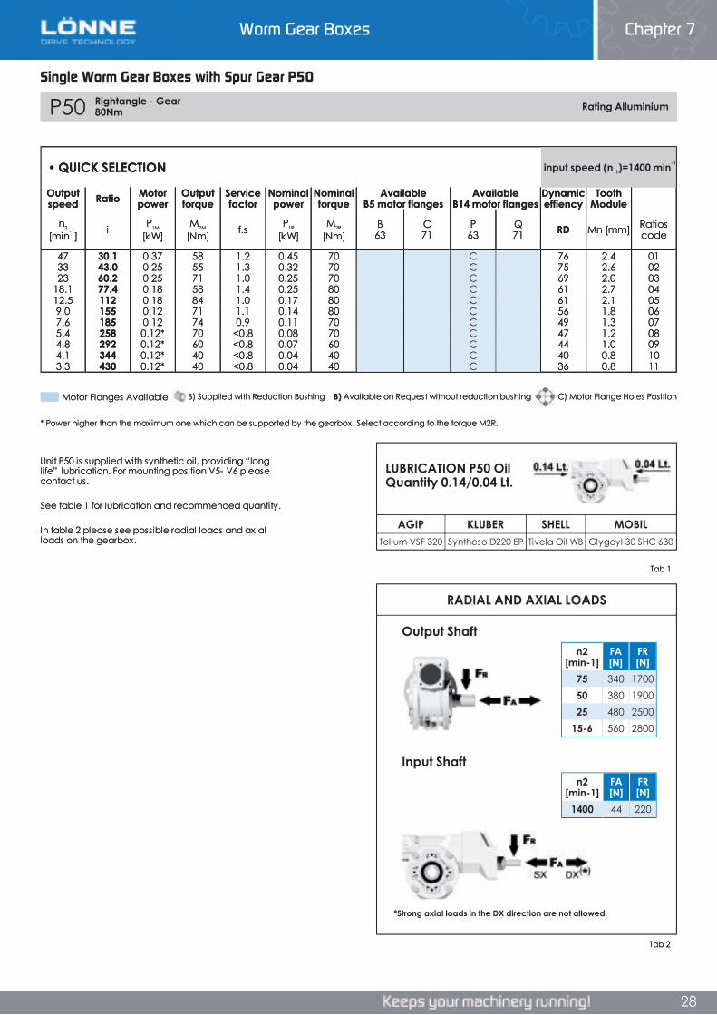
Worm Gear Boxes Chapter 7
28
Single Worm Gear Boxes with Spur Gear P50
P50 Rightangle - Gear 80Nm Rating Alluminium
RADIAL AND AXIAL LOADS
n2[min-1]
FA[N]
FR[N]
1400 44 220
n2[min-1]
FA[N]
FR[N]
75 340 170050 380 190025 480 2500
15-6 560 2800
AGIP KLUBER SHELL MOBILTelium VSF 320 Syntheso D220 EP Tivela Oil WB Glygoyl 30 SHC 630
• QUICK SELECTION input speed (n 1)=1400 min-1
Outputspeed Ratio Motor
powerOutputtorque
Servicefactor
Nominalpower
Nominaltorque
AvailableB5 motor flanges
AvailableB14 motor flanges
Dynamiceffiency
ToothModule
n2
[min-1] i P1M
[kW]M2M
[Nm] f.s P1R
[kW]M2R
[Nm]B63
C71
P63
Q71 RD Mn [mm] Ratios
code
47 30.1 0.37 58 1.2 0.45 70 C 76 2.4 0133 43.0 0.25 55 1.3 0.32 70 C 75 2.6 0223 60.2 0.25 71 1.0 0.25 70 C 69 2.0 03
18.1 77.4 0.18 58 1.4 0.25 80 C 61 2.7 0412.5 112 0.18 84 1.0 0.17 80 C 61 2.1 059.0 155 0.12 71 1.1 0.14 80 C 56 1.8 067.6 185 0.12 74 0.9 0.11 70 C 49 1.3 075.4 258 0.12* 70 <0.8 0.08 70 C 47 1.2 084.8 292 0.12* 60 <0.8 0.07 60 C 44 1.0 094.1 344 0.12* 40 <0.8 0.04 40 C 40 0.8 103.3 430 0.12* 40 <0.8 0.04 40 C 36 0.8 11
Unit P50 is supplied with synthetic oil, providing “long life” lubrication. For mounting position V5- V6 please contact us.
See table 1 for lubrication and recommended quantity.
In table 2 please see possible radial loads and axial loads on the gearbox.
Input Shaft
Output Shaft
*Strong axial loads in the DX direction are not allowed.
* Power higher than the maximum one which can be supported by the gearbox. Select according to the torque M2R.
LUBRICATION P50 Oil Quantity 0.14/0.04 Lt.
Tab 2
Tab 1
B) Supplied with Reduction Bushing B) Available on Request without reduction bushing C) Motor Flange Holes PositionMotor Flanges Available
Single Worm Gear Boxes with Spur Gear P50
Chapter 7Worm Gear Boxes
Single Worm Gear Boxes with Spur Gear P50
P50 Rightangle - Gear 80Nm Rating Alluminium
RADIAL AND AXIAL LOADS
n2[min-1]
FA[N]
FR[N]
1400 44 220
n2[min-1]
FA[N]
FR[N]
75 340 170050 380 190025 480 2500
15-6 560 2800
AGIP KLUBER SHELL MOBILTelium VSF 320 Syntheso D220 EP Tivela Oil WB Glygoyl 30 SHC 630
• QUICK SELECTION input speed (n 1)=1400 min-1
Outputspeed Ratio Motor
powerOutputtorque
Servicefactor
Nominalpower
Nominaltorque
AvailableB5 motor flanges
AvailableB14 motor flanges
Dynamiceffiency
ToothModule
n2
[min-1] i P1M
[kW]M2M
[Nm] f.s P1R
[kW]M2R
[Nm]B63
C71
P63
Q71 RD Mn [mm] Ratios
code
47 30.1 0.37 58 1.2 0.45 70 C 76 2.4 0133 43.0 0.25 55 1.3 0.32 70 C 75 2.6 0223 60.2 0.25 71 1.0 0.25 70 C 69 2.0 03
18.1 77.4 0.18 58 1.4 0.25 80 C 61 2.7 0412.5 112 0.18 84 1.0 0.17 80 C 61 2.1 059.0 155 0.12 71 1.1 0.14 80 C 56 1.8 067.6 185 0.12 74 0.9 0.11 70 C 49 1.3 075.4 258 0.12* 70 <0.8 0.08 70 C 47 1.2 084.8 292 0.12* 60 <0.8 0.07 60 C 44 1.0 094.1 344 0.12* 40 <0.8 0.04 40 C 40 0.8 103.3 430 0.12* 40 <0.8 0.04 40 C 36 0.8 11
Unit P50 is supplied with synthetic oil, providing “long life” lubrication. For mounting position V5- V6 please contact us.
See table 1 for lubrication and recommended quantity.
In table 2 please see possible radial loads and axial loads on the gearbox.
Input Shaft
Output Shaft
*Strong axial loads in the DX direction are not allowed.
* Power higher than the maximum one which can be supported by the gearbox. Select according to the torque M2R.
LUBRICATION P50 Oil Quantity 0.14/0.04 Lt.
Tab 2
Tab 1
B) Supplied with Reduction Bushing B) Available on Request without reduction bushing C) Motor Flange Holes PositionMotor Flanges Available
28
P50 Rightangle - Gear 80Nm Rating Alluminium
RADIAL AND AXIAL LOADS
n2[min-1]
FA[N]
FR[N]
1400 44 220
n2[min-1]
FA[N]
FR[N]
75 340 170050 380 190025 480 2500
15-6 560 2800
AGIP KLUBER SHELL MOBILTelium VSF 320 Syntheso D220 EP Tivela Oil WB Glygoyl 30 SHC 630
• QUICK SELECTION input speed (n 1)=1400 min-1
Outputspeed Ratio Motor
powerOutputtorque
Servicefactor
Nominalpower
Nominaltorque
AvailableB5 motor flanges
AvailableB14 motor flanges
Dynamiceffiency
ToothModule
n2
[min-1] i P1M
[kW]M2M
[Nm] f.s P1R
[kW]M2R
[Nm]B63
C71
P63
Q71 RD Mn [mm] Ratios
code
47 30.1 0.37 58 1.2 0.45 70 C 76 2.4 0133 43.0 0.25 55 1.3 0.32 70 C 75 2.6 0223 60.2 0.25 71 1.0 0.25 70 C 69 2.0 03
18.1 77.4 0.18 58 1.4 0.25 80 C 61 2.7 0412.5 112 0.18 84 1.0 0.17 80 C 61 2.1 059.0 155 0.12 71 1.1 0.14 80 C 56 1.8 067.6 185 0.12 74 0.9 0.11 70 C 49 1.3 075.4 258 0.12* 70 <0.8 0.08 70 C 47 1.2 084.8 292 0.12* 60 <0.8 0.07 60 C 44 1.0 094.1 344 0.12* 40 <0.8 0.04 40 C 40 0.8 103.3 430 0.12* 40 <0.8 0.04 40 C 36 0.8 11
Unit P50 is supplied with synthetic oil, providing “long life” lubrication. For mounting position V5- V6 please contact us.
See table 1 for lubrication and recommended quantity.
In table 2 please see possible radial loads and axial loads on the gearbox.
Input Shaft
Output Shaft
*Strong axial loads in the DX direction are not allowed.
* Power higher than the maximum one which can be supported by the gearbox. Select according to the torque M2R.
LUBRICATION P50 Oil Quantity 0.14/0.04 Lt.
Tab 2
Tab 1
B) Supplied with Reduction Bushing B) Available on Request without reduction bushing C) Motor Flange Holes PositionMotor Flanges Available
Worm Gear Boxes Chapter 7
28
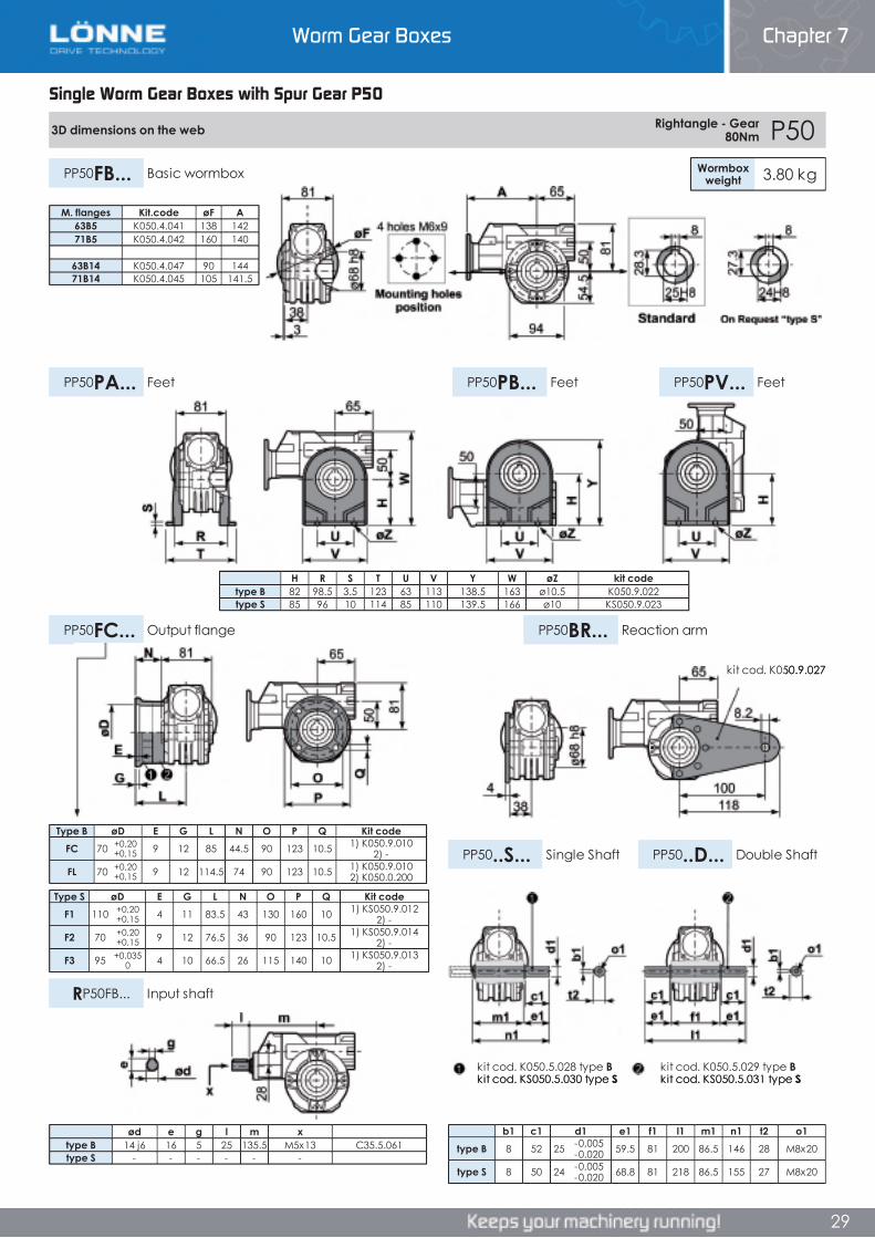
Worm Gear Boxes Chapter 7
28
Single Worm Gear Boxes with Spur Gear P50
P50 Rightangle - Gear 80Nm Rating Alluminium
RADIAL AND AXIAL LOADS
n2[min-1]
FA[N]
FR[N]
1400 44 220
n2[min-1]
FA[N]
FR[N]
75 340 170050 380 190025 480 2500
15-6 560 2800
AGIP KLUBER SHELL MOBILTelium VSF 320 Syntheso D220 EP Tivela Oil WB Glygoyl 30 SHC 630
• QUICK SELECTION input speed (n 1)=1400 min-1
Outputspeed Ratio Motor
powerOutputtorque
Servicefactor
Nominalpower
Nominaltorque
AvailableB5 motor flanges
AvailableB14 motor flanges
Dynamiceffiency
ToothModule
n2
[min-1] i P1M
[kW]M2M
[Nm] f.s P1R
[kW]M2R
[Nm]B63
C71
P63
Q71 RD Mn [mm] Ratios
code
47 30.1 0.37 58 1.2 0.45 70 C 76 2.4 0133 43.0 0.25 55 1.3 0.32 70 C 75 2.6 0223 60.2 0.25 71 1.0 0.25 70 C 69 2.0 03
18.1 77.4 0.18 58 1.4 0.25 80 C 61 2.7 0412.5 112 0.18 84 1.0 0.17 80 C 61 2.1 059.0 155 0.12 71 1.1 0.14 80 C 56 1.8 067.6 185 0.12 74 0.9 0.11 70 C 49 1.3 075.4 258 0.12* 70 <0.8 0.08 70 C 47 1.2 084.8 292 0.12* 60 <0.8 0.07 60 C 44 1.0 094.1 344 0.12* 40 <0.8 0.04 40 C 40 0.8 103.3 430 0.12* 40 <0.8 0.04 40 C 36 0.8 11
Unit P50 is supplied with synthetic oil, providing “long life” lubrication. For mounting position V5- V6 please contact us.
See table 1 for lubrication and recommended quantity.
In table 2 please see possible radial loads and axial loads on the gearbox.
Input Shaft
Output Shaft
*Strong axial loads in the DX direction are not allowed.
* Power higher than the maximum one which can be supported by the gearbox. Select according to the torque M2R.
LUBRICATION P50 Oil Quantity 0.14/0.04 Lt.
Tab 2
Tab 1
B) Supplied with Reduction Bushing B) Available on Request without reduction bushing C) Motor Flange Holes PositionMotor Flanges Available
Single Worm Gear Boxes with Spur Gear P50
Chapter 7Worm Gear Boxes
Single Worm Gear Boxes with Spur Gear P50
P50 Rightangle - Gear 80Nm Rating Alluminium
RADIAL AND AXIAL LOADS
n2[min-1]
FA[N]
FR[N]
1400 44 220
n2[min-1]
FA[N]
FR[N]
75 340 170050 380 190025 480 2500
15-6 560 2800
AGIP KLUBER SHELL MOBILTelium VSF 320 Syntheso D220 EP Tivela Oil WB Glygoyl 30 SHC 630
• QUICK SELECTION input speed (n 1)=1400 min-1
Outputspeed Ratio Motor
powerOutputtorque
Servicefactor
Nominalpower
Nominaltorque
AvailableB5 motor flanges
AvailableB14 motor flanges
Dynamiceffiency
ToothModule
n2
[min-1] i P1M
[kW]M2M
[Nm] f.s P1R
[kW]M2R
[Nm]B63
C71
P63
Q71 RD Mn [mm] Ratios
code
47 30.1 0.37 58 1.2 0.45 70 C 76 2.4 0133 43.0 0.25 55 1.3 0.32 70 C 75 2.6 0223 60.2 0.25 71 1.0 0.25 70 C 69 2.0 03
18.1 77.4 0.18 58 1.4 0.25 80 C 61 2.7 0412.5 112 0.18 84 1.0 0.17 80 C 61 2.1 059.0 155 0.12 71 1.1 0.14 80 C 56 1.8 067.6 185 0.12 74 0.9 0.11 70 C 49 1.3 075.4 258 0.12* 70 <0.8 0.08 70 C 47 1.2 084.8 292 0.12* 60 <0.8 0.07 60 C 44 1.0 094.1 344 0.12* 40 <0.8 0.04 40 C 40 0.8 103.3 430 0.12* 40 <0.8 0.04 40 C 36 0.8 11
Unit P50 is supplied with synthetic oil, providing “long life” lubrication. For mounting position V5- V6 please contact us.
See table 1 for lubrication and recommended quantity.
In table 2 please see possible radial loads and axial loads on the gearbox.
Input Shaft
Output Shaft
*Strong axial loads in the DX direction are not allowed.
* Power higher than the maximum one which can be supported by the gearbox. Select according to the torque M2R.
LUBRICATION P50 Oil Quantity 0.14/0.04 Lt.
Tab 2
Tab 1
B) Supplied with Reduction Bushing B) Available on Request without reduction bushing C) Motor Flange Holes PositionMotor Flanges Available
28
P50 Rightangle - Gear 80Nm Rating Alluminium
RADIAL AND AXIAL LOADS
n2[min-1]
FA[N]
FR[N]
1400 44 220
n2[min-1]
FA[N]
FR[N]
75 340 170050 380 190025 480 2500
15-6 560 2800
AGIP KLUBER SHELL MOBILTelium VSF 320 Syntheso D220 EP Tivela Oil WB Glygoyl 30 SHC 630
• QUICK SELECTION input speed (n 1)=1400 min-1
Outputspeed Ratio Motor
powerOutputtorque
Servicefactor
Nominalpower
Nominaltorque
AvailableB5 motor flanges
AvailableB14 motor flanges
Dynamiceffiency
ToothModule
n2
[min-1] i P1M
[kW]M2M
[Nm] f.s P1R
[kW]M2R
[Nm]B63
C71
P63
Q71 RD Mn [mm] Ratios
code
47 30.1 0.37 58 1.2 0.45 70 C 76 2.4 0133 43.0 0.25 55 1.3 0.32 70 C 75 2.6 0223 60.2 0.25 71 1.0 0.25 70 C 69 2.0 03
18.1 77.4 0.18 58 1.4 0.25 80 C 61 2.7 0412.5 112 0.18 84 1.0 0.17 80 C 61 2.1 059.0 155 0.12 71 1.1 0.14 80 C 56 1.8 067.6 185 0.12 74 0.9 0.11 70 C 49 1.3 075.4 258 0.12* 70 <0.8 0.08 70 C 47 1.2 084.8 292 0.12* 60 <0.8 0.07 60 C 44 1.0 094.1 344 0.12* 40 <0.8 0.04 40 C 40 0.8 103.3 430 0.12* 40 <0.8 0.04 40 C 36 0.8 11
Unit P50 is supplied with synthetic oil, providing “long life” lubrication. For mounting position V5- V6 please contact us.
See table 1 for lubrication and recommended quantity.
In table 2 please see possible radial loads and axial loads on the gearbox.
Input Shaft
Output Shaft
*Strong axial loads in the DX direction are not allowed.
* Power higher than the maximum one which can be supported by the gearbox. Select according to the torque M2R.
LUBRICATION P50 Oil Quantity 0.14/0.04 Lt.
Tab 2
Tab 1
B) Supplied with Reduction Bushing B) Available on Request without reduction bushing C) Motor Flange Holes PositionMotor Flanges Available
Worm Gear Boxes Chapter 7
28
Worm Gear Boxes Chapter 7
29
Single Worm Gear Boxes with Spur Gear P50
3D dimensions on the web Rightangle - Gear 80Nm P50
Wormboxweight 3.80 kgPP50FB... Basic wormbox
PP50PB... FeetPP50PA... Feet PP50PV... Feet
PP50FC... Output flange PP50BR... Reaction arm
PP50..S... Single Shaft PP50..D... Double Shaft
RP50FB... Input shaft
Type B øD E G L N O P Q Kit codeFC 70 +0,20
+0,15 9 12 85 44.5 90 123 10.5 1) K050.9.010 2) -
FL 70 +0,20+0,15 9 12 114.5 74 90 123 10.5 1) K050.9.010
2) K050.0.200
Type S øD E G L N O P Q Kit codeF1 110 +0,20
+0,15 4 11 83.5 43 130 160 10 1) KS050.9.012 2) -
F2 70 +0,20+0,15 9 12 76.5 36 90 123 10.5 1) KS050.9.014
2) -
F3 95 +0,0350 4 10 66.5 26 115 140 10 1) KS050.9.013
2) -
b1 c1 d1 e1 f1 l1 m1 n1 t2 o1type B 8 52 25 -0,005
-0,020 59.5 81 200 86.5 146 28 M8x20
type S 8 50 24 -0,005-0,020 68.8 81 218 86.5 155 27 M8x20
H R S T U V Y W øZ kit codetype B 82 98.5 3.5 123 63 113 138.5 163 ø10.5 K050.9.022type S 85 96 10 114 85 110 139.5 166 ø10 KS050.9.023
ød e g l m xtype B 14 j6 16 5 25 135.5 M5x13 C35.5.061type S - - - - - -
M. flanges Kit.code øF A63B5 K050.4.041 138 14271B5 K050.4.042 160 140
63B14 K050.4.047 90 14471B14 K050.4.045 105 141.5
kit cod. K050.5.029 type Bkit cod. KS050.5.031 type S
kit cod. K050.5.028 type Bkit cod. KS050.5.030 type S
kit cod. K050.9.027
Single Worm Gear Boxes with Spur Gear P50
Chapter 7Worm Gear Boxes
Single Worm Gear Boxes with Spur Gear P50
3D dimensions on the web Rightangle - Gear 80Nm P50
Wormboxweight 3.80 kgPP50FB... Basic wormbox
PP50PB... FeetPP50PA... Feet PP50PV... Feet
PP50FC... Output flange PP50BR... Reaction arm
PP50..S... Single Shaft PP50..D... Double Shaft
RP50FB... Input shaft
Type B øD E G L N O P Q Kit codeFC 70 +0,20
+0,15 9 12 85 44.5 90 123 10.5 1) K050.9.010 2) -
FL 70 +0,20+0,15 9 12 114.5 74 90 123 10.5 1) K050.9.010
2) K050.0.200
Type S øD E G L N O P Q Kit codeF1 110 +0,20
+0,15 4 11 83.5 43 130 160 10 1) KS050.9.012 2) -
F2 70 +0,20+0,15 9 12 76.5 36 90 123 10.5 1) KS050.9.014
2) -
F3 95 +0,0350 4 10 66.5 26 115 140 10 1) KS050.9.013
2) -
b1 c1 d1 e1 f1 l1 m1 n1 t2 o1type B 8 52 25 -0,005
-0,020 59.5 81 200 86.5 146 28 M8x20
type S 8 50 24 -0,005-0,020 68.8 81 218 86.5 155 27 M8x20
H R S T U V Y W øZ kit codetype B 82 98.5 3.5 123 63 113 138.5 163 ø10.5 K050.9.022type S 85 96 10 114 85 110 139.5 166 ø10 KS050.9.023
ød e g l m xtype B 14 j6 16 5 25 135.5 M5x13 C35.5.061type S - - - - - -
M. flanges Kit.code øF A63B5 K050.4.041 138 14271B5 K050.4.042 160 140
63B14 K050.4.047 90 14471B14 K050.4.045 105 141.5
kit cod. K050.5.029 type Bkit cod. KS050.5.031 type S
kit cod. K050.5.028 type Bkit cod. KS050.5.030 type S
kit cod. K050.9.027
29
3D dimensions on the web Rightangle - Gear 80Nm P50
Wormboxweight 3.80 kgPP50FB... Basic wormbox
PP50PB... FeetPP50PA... Feet PP50PV... Feet
PP50FC... Output flange PP50BR... Reaction arm
PP50..S... Single Shaft PP50..D... Double Shaft
RP50FB... Input shaft
Type B øD E G L N O P Q Kit codeFC 70 +0,20
+0,15 9 12 85 44.5 90 123 10.5 1) K050.9.010 2) -
FL 70 +0,20+0,15 9 12 114.5 74 90 123 10.5 1) K050.9.010
2) K050.0.200
Type S øD E G L N O P Q Kit codeF1 110 +0,20
+0,15 4 11 83.5 43 130 160 10 1) KS050.9.012 2) -
F2 70 +0,20+0,15 9 12 76.5 36 90 123 10.5 1) KS050.9.014
2) -
F3 95 +0,0350 4 10 66.5 26 115 140 10 1) KS050.9.013
2) -
b1 c1 d1 e1 f1 l1 m1 n1 t2 o1type B 8 52 25 -0,005
-0,020 59.5 81 200 86.5 146 28 M8x20
type S 8 50 24 -0,005-0,020 68.8 81 218 86.5 155 27 M8x20
H R S T U V Y W øZ kit codetype B 82 98.5 3.5 123 63 113 138.5 163 ø10.5 K050.9.022type S 85 96 10 114 85 110 139.5 166 ø10 KS050.9.023
ød e g l m xtype B 14 j6 16 5 25 135.5 M5x13 C35.5.061type S - - - - - -
M. flanges Kit.code øF A63B5 K050.4.041 138 14271B5 K050.4.042 160 140
63B14 K050.4.047 90 14471B14 K050.4.045 105 141.5
kit cod. K050.5.029 type Bkit cod. KS050.5.031 type S
kit cod. K050.5.028 type Bkit cod. KS050.5.030 type S
kit cod. K050.9.027
Worm Gear Boxes Chapter 7
29
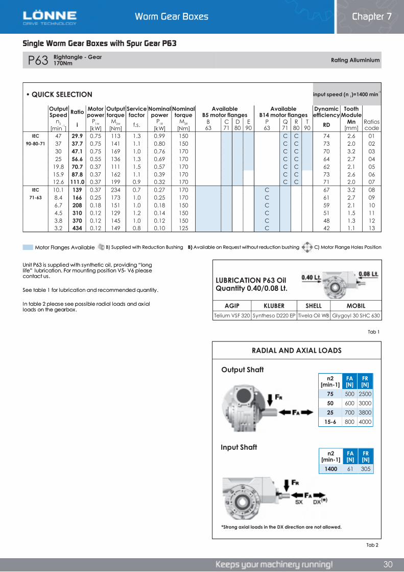
Worm Gear Boxes Chapter 7
30
Single Worm Gear Boxes with Spur Gear P63
P63 Rightangle - Gear 170Nm Rating Alluminium
RADIAL AND AXIAL LOADS
n2[min-1]
FA[N]
FR[N]
1400 61 305
n2[min-1]
FA[N]
FR[N]
75 500 250050 600 300025 700 3800
15-6 800 4000
AGIP KLUBER SHELL MOBILTelium VSF 320 Syntheso D220 EP Tivela Oil WB Glygoyl 30 SHC 630
• QUICK SELECTION input speed (n 1)=1400 min-1
OutputSpeed Ratio Motor
powerOutputtorque
Servicefactor
Nominalpower
Nominaltorque
AvailableB5 motor flanges
AvailableB14 motor flanges
Dynamicefficiency
ToothModule
n2
[min-1] i P1M
[kW]M2M
[Nm] f.s. P1R
[kW]M2R
[Nm]B63
C71
D80
E90
P63
Q71
R80
T90 RD Mn
[mm]Ratioscode
IEC 47 29.9 0.75 113 1.3 0.99 150 C C 74 2.6 0190-80-71 37 37.7 0.75 141 1.1 0.80 150 C C 73 2.0 02
30 47.1 0.75 169 1.0 0.76 170 C C 70 3.2 0325 56.6 0.55 136 1.3 0.69 170 C C 64 2.7 04
19.8 70.7 0.37 111 1.5 0.57 170 C C 62 2.1 0515.9 87.8 0.37 162 1.1 0.39 170 C C 73 2.6 0612.6 111.0 0.37 199 0.9 0.32 170 C C 71 2.0 07
IEC 10.1 139 0.37 234 0.7 0.27 170 C 67 3.2 0871-63 8.4 166 0.25 173 1.0 0.25 170 C 61 2.7 09
6.7 208 0.18 151 1.0 0.18 150 C 59 2.1 104.5 310 0.12 129 1.2 0.14 150 C 51 1.5 113.8 370 0.12 145 1.0 0.12 150 C 48 1.3 123.2 434 0.12 149 0.8 0.10 125 C 42 1.1 13
Unit P63 is supplied with synthetic oil, providing “long life” lubrication. For mounting position V5- V6 please contact us.
See table 1 for lubrication and recommended quantity.
In table 2 please see possible radial loads and axial loads on the gearbox.
Input Shaft
Output Shaft
*Strong axial loads in the DX direction are not allowed.
Tab 2
LUBRICATION P63 Oil Quantity 0.40/0.08 Lt.
Tab 1
B) Supplied with Reduction Bushing B) Available on Request without reduction bushing C) Motor Flange Holes PositionMotor Flanges Available
Single Worm Gear Boxes with Spur Gear P63
Chapter 7Worm Gear Boxes
Single Worm Gear Boxes with Spur Gear P63
P63 Rightangle - Gear 170Nm Rating Alluminium
RADIAL AND AXIAL LOADS
n2[min-1]
FA[N]
FR[N]
1400 61 305
n2[min-1]
FA[N]
FR[N]
75 500 250050 600 300025 700 3800
15-6 800 4000
AGIP KLUBER SHELL MOBILTelium VSF 320 Syntheso D220 EP Tivela Oil WB Glygoyl 30 SHC 630
• QUICK SELECTION input speed (n 1)=1400 min-1
OutputSpeed Ratio Motor
powerOutputtorque
Servicefactor
Nominalpower
Nominaltorque
AvailableB5 motor flanges
AvailableB14 motor flanges
Dynamicefficiency
ToothModule
n2
[min-1] i P1M
[kW]M2M
[Nm] f.s. P1R
[kW]M2R
[Nm]B63
C71
D80
E90
P63
Q71
R80
T90 RD Mn
[mm]Ratioscode
IEC 47 29.9 0.75 113 1.3 0.99 150 C C 74 2.6 0190-80-71 37 37.7 0.75 141 1.1 0.80 150 C C 73 2.0 02
30 47.1 0.75 169 1.0 0.76 170 C C 70 3.2 0325 56.6 0.55 136 1.3 0.69 170 C C 64 2.7 04
19.8 70.7 0.37 111 1.5 0.57 170 C C 62 2.1 0515.9 87.8 0.37 162 1.1 0.39 170 C C 73 2.6 0612.6 111.0 0.37 199 0.9 0.32 170 C C 71 2.0 07
IEC 10.1 139 0.37 234 0.7 0.27 170 C 67 3.2 0871-63 8.4 166 0.25 173 1.0 0.25 170 C 61 2.7 09
6.7 208 0.18 151 1.0 0.18 150 C 59 2.1 104.5 310 0.12 129 1.2 0.14 150 C 51 1.5 113.8 370 0.12 145 1.0 0.12 150 C 48 1.3 123.2 434 0.12 149 0.8 0.10 125 C 42 1.1 13
Unit P63 is supplied with synthetic oil, providing “long life” lubrication. For mounting position V5- V6 please contact us.
See table 1 for lubrication and recommended quantity.
In table 2 please see possible radial loads and axial loads on the gearbox.
Input Shaft
Output Shaft
*Strong axial loads in the DX direction are not allowed.
Tab 2
LUBRICATION P63 Oil Quantity 0.40/0.08 Lt.
Tab 1
B) Supplied with Reduction Bushing B) Available on Request without reduction bushing C) Motor Flange Holes PositionMotor Flanges Available
30
P63 Rightangle - Gear 170Nm Rating Alluminium
RADIAL AND AXIAL LOADS
n2[min-1]
FA[N]
FR[N]
1400 61 305
n2[min-1]
FA[N]
FR[N]
75 500 250050 600 300025 700 3800
15-6 800 4000
AGIP KLUBER SHELL MOBILTelium VSF 320 Syntheso D220 EP Tivela Oil WB Glygoyl 30 SHC 630
• QUICK SELECTION input speed (n 1)=1400 min-1
OutputSpeed Ratio Motor
powerOutputtorque
Servicefactor
Nominalpower
Nominaltorque
AvailableB5 motor flanges
AvailableB14 motor flanges
Dynamicefficiency
ToothModule
n2
[min-1] i P1M
[kW]M2M
[Nm] f.s. P1R
[kW]M2R
[Nm]B63
C71
D80
E90
P63
Q71
R80
T90 RD Mn
[mm]Ratioscode
IEC 47 29.9 0.75 113 1.3 0.99 150 C C 74 2.6 0190-80-71 37 37.7 0.75 141 1.1 0.80 150 C C 73 2.0 02
30 47.1 0.75 169 1.0 0.76 170 C C 70 3.2 0325 56.6 0.55 136 1.3 0.69 170 C C 64 2.7 04
19.8 70.7 0.37 111 1.5 0.57 170 C C 62 2.1 0515.9 87.8 0.37 162 1.1 0.39 170 C C 73 2.6 0612.6 111.0 0.37 199 0.9 0.32 170 C C 71 2.0 07
IEC 10.1 139 0.37 234 0.7 0.27 170 C 67 3.2 0871-63 8.4 166 0.25 173 1.0 0.25 170 C 61 2.7 09
6.7 208 0.18 151 1.0 0.18 150 C 59 2.1 104.5 310 0.12 129 1.2 0.14 150 C 51 1.5 113.8 370 0.12 145 1.0 0.12 150 C 48 1.3 123.2 434 0.12 149 0.8 0.10 125 C 42 1.1 13
Unit P63 is supplied with synthetic oil, providing “long life” lubrication. For mounting position V5- V6 please contact us.
See table 1 for lubrication and recommended quantity.
In table 2 please see possible radial loads and axial loads on the gearbox.
Input Shaft
Output Shaft
*Strong axial loads in the DX direction are not allowed.
Tab 2
LUBRICATION P63 Oil Quantity 0.40/0.08 Lt.
Tab 1
B) Supplied with Reduction Bushing B) Available on Request without reduction bushing C) Motor Flange Holes PositionMotor Flanges Available
Worm Gear Boxes Chapter 7
30
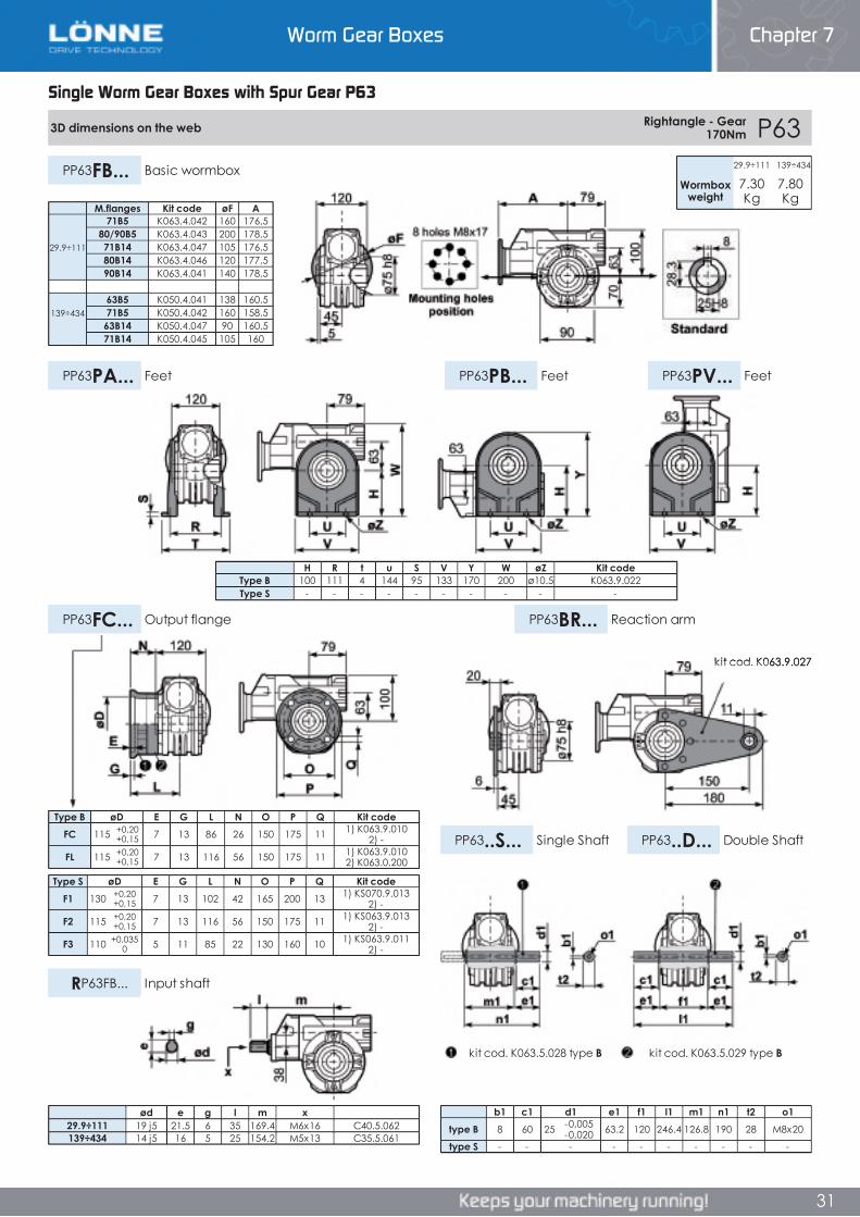
Worm Gear Boxes Chapter 7
31
Single Worm Gear Boxes with Spur Gear P63
3D dimensions on the web Rightangle - Gear 170Nm P63
PP63FB... Basic wormbox
PP63PB... FeetPP63PA... Feet PP63PV... Feet
PP63FC... Output flange PP63BR... Reaction arm
PP63..S... Single Shaft PP63..D... Double Shaft
RP63FB... Input shaft
29.9÷111 139÷434
Wormboxweight
7.30Kg
7.80Kg
Type B øD E G L N O P Q Kit codeFC 115 +0,20
+0,15 7 13 86 26 150 175 11 1) K063.9.010 2) -
FL 115 +0,20+0,15 7 13 116 56 150 175 11 1) K063.9.010
2) K063.0.200
Type S øD E G L N O P Q Kit codeF1 130 +0,20
+0,15 7 13 102 42 165 200 13 1) KS070.9.013 2) -
F2 115 +0,20+0,15 7 13 116 56 150 175 11 1) KS063.9.013
2) -
F3 110 +0,0350 5 11 85 22 130 160 10 1) KS063.9.011
2) -
b1 c1 d1 e1 f1 l1 m1 n1 t2 o1type B 8 60 25 -0,005
-0,020 63.2 120 246.4 126.8 190 28 M8x20
type S - - - - - - - - - -
M.flanges Kit code øF A71B5 K063.4.042 160 176,5
80/90B5 K063.4.043 200 178,529.9÷111 71B14 K063.4.047 105 176,5
80B14 K063.4.046 120 177,590B14 K063.4.041 140 178,5
63B5 K050.4.041 138 160,5139÷434 71B5 K050.4.042 160 158,5
63B14 K050.4.047 90 160,571B14 K050.4.045 105 160
H R t u S V Y W øZ Kit codeType B 100 111 4 144 95 133 170 200 ø10.5 K063.9.022Type S - - - - - - - - - -
ød e g l m x29.9÷111 19 j5 21.5 6 35 169.4 M6x16 C40.5.062139÷434 14 j5 16 5 25 154.2 M5x13 C35.5.061
kit cod. K063.5.029 type Bkit cod. K063.5.028 type B
kit cod. K063.9.027
Single Worm Gear Boxes with Spur Gear P63
Chapter 7Worm Gear Boxes
Single Worm Gear Boxes with Spur Gear P63
3D dimensions on the web Rightangle - Gear 170Nm P63
PP63FB... Basic wormbox
PP63PB... FeetPP63PA... Feet PP63PV... Feet
PP63FC... Output flange PP63BR... Reaction arm
PP63..S... Single Shaft PP63..D... Double Shaft
RP63FB... Input shaft
29.9÷111 139÷434
Wormboxweight
7.30Kg
7.80Kg
Type B øD E G L N O P Q Kit codeFC 115 +0,20
+0,15 7 13 86 26 150 175 11 1) K063.9.010 2) -
FL 115 +0,20+0,15 7 13 116 56 150 175 11 1) K063.9.010
2) K063.0.200
Type S øD E G L N O P Q Kit codeF1 130 +0,20
+0,15 7 13 102 42 165 200 13 1) KS070.9.013 2) -
F2 115 +0,20+0,15 7 13 116 56 150 175 11 1) KS063.9.013
2) -
F3 110 +0,0350 5 11 85 22 130 160 10 1) KS063.9.011
2) -
b1 c1 d1 e1 f1 l1 m1 n1 t2 o1type B 8 60 25 -0,005
-0,020 63.2 120 246.4 126.8 190 28 M8x20
type S - - - - - - - - - -
M.flanges Kit code øF A71B5 K063.4.042 160 176,5
80/90B5 K063.4.043 200 178,529.9÷111 71B14 K063.4.047 105 176,5
80B14 K063.4.046 120 177,590B14 K063.4.041 140 178,5
63B5 K050.4.041 138 160,5139÷434 71B5 K050.4.042 160 158,5
63B14 K050.4.047 90 160,571B14 K050.4.045 105 160
H R t u S V Y W øZ Kit codeType B 100 111 4 144 95 133 170 200 ø10.5 K063.9.022Type S - - - - - - - - - -
ød e g l m x29.9÷111 19 j5 21.5 6 35 169.4 M6x16 C40.5.062139÷434 14 j5 16 5 25 154.2 M5x13 C35.5.061
kit cod. K063.5.029 type Bkit cod. K063.5.028 type B
kit cod. K063.9.027
31
3D dimensions on the web Rightangle - Gear 170Nm P63
PP63FB... Basic wormbox
PP63PB... FeetPP63PA... Feet PP63PV... Feet
PP63FC... Output flange PP63BR... Reaction arm
PP63..S... Single Shaft PP63..D... Double Shaft
RP63FB... Input shaft
29.9÷111 139÷434
Wormboxweight
7.30Kg
7.80Kg
Type B øD E G L N O P Q Kit codeFC 115 +0,20
+0,15 7 13 86 26 150 175 11 1) K063.9.010 2) -
FL 115 +0,20+0,15 7 13 116 56 150 175 11 1) K063.9.010
2) K063.0.200
Type S øD E G L N O P Q Kit codeF1 130 +0,20
+0,15 7 13 102 42 165 200 13 1) KS070.9.013 2) -
F2 115 +0,20+0,15 7 13 116 56 150 175 11 1) KS063.9.013
2) -
F3 110 +0,0350 5 11 85 22 130 160 10 1) KS063.9.011
2) -
b1 c1 d1 e1 f1 l1 m1 n1 t2 o1type B 8 60 25 -0,005
-0,020 63.2 120 246.4 126.8 190 28 M8x20
type S - - - - - - - - - -
M.flanges Kit code øF A71B5 K063.4.042 160 176,5
80/90B5 K063.4.043 200 178,529.9÷111 71B14 K063.4.047 105 176,5
80B14 K063.4.046 120 177,590B14 K063.4.041 140 178,5
63B5 K050.4.041 138 160,5139÷434 71B5 K050.4.042 160 158,5
63B14 K050.4.047 90 160,571B14 K050.4.045 105 160
H R t u S V Y W øZ Kit codeType B 100 111 4 144 95 133 170 200 ø10.5 K063.9.022Type S - - - - - - - - - -
ød e g l m x29.9÷111 19 j5 21.5 6 35 169.4 M6x16 C40.5.062139÷434 14 j5 16 5 25 154.2 M5x13 C35.5.061
kit cod. K063.5.029 type Bkit cod. K063.5.028 type B
kit cod. K063.9.027
Worm Gear Boxes Chapter 7
31
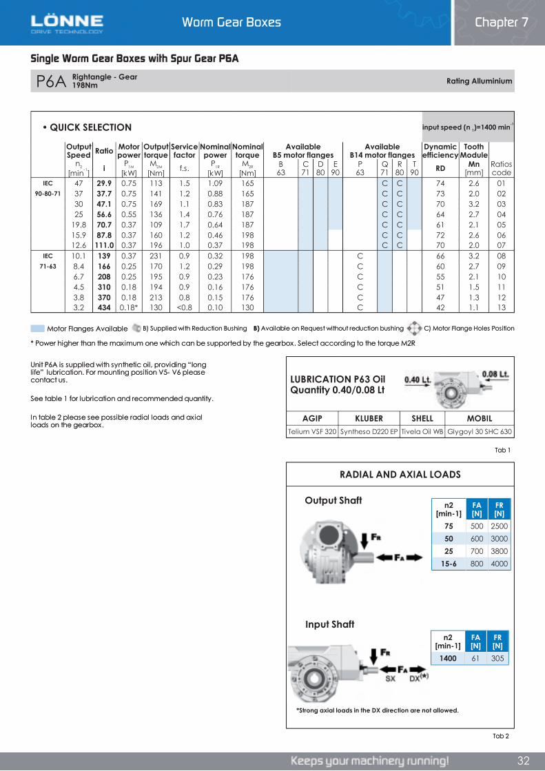
Worm Gear Boxes Chapter 7
32
Single Worm Gear Boxes with Spur Gear P6A
P6A Rightangle - Gear 198Nm Rating Alluminium
AGIP KLUBER SHELL MOBILTelium VSF 320 Syntheso D220 EP Tivela Oil WB Glygoyl 30 SHC 630
RADIAL AND AXIAL LOADS
n2[min-1]
FA[N]
FR[N]
1400 61 305
n2[min-1]
FA[N]
FR[N]
75 500 250050 600 300025 700 3800
15-6 800 4000
• QUICK SELECTION input speed (n 1)=1400 min-1
OutputSpeed Ratio Motor
powerOutputtorque
Servicefactor
Nominalpower
Nominaltorque
AvailableB5 motor flanges
AvailableB14 motor flanges
Dynamicefficiency
ToothModule
n2
[min-1] i P1M
[kW]M2M
[Nm] f.s. P1R
[kW]M2R
[Nm]B63
C71
D80
E90
P63
Q71
R80
T90 RD Mn
[mm]Ratioscode
IEC 47 29.9 0.75 113 1.5 1.09 165 C C 74 2.6 0190-80-71 37 37.7 0.75 141 1.2 0.88 165 C C 73 2.0 02
30 47.1 0.75 169 1.1 0.83 187 C C 70 3.2 0325 56.6 0.55 136 1.4 0.76 187 C C 64 2.7 04
19.8 70.7 0.37 109 1.7 0.64 187 C C 61 2.1 0515.9 87.8 0.37 160 1.2 0.46 198 C C 72 2.6 0612.6 111.0 0.37 196 1.0 0.37 198 C C 70 2.0 07
IEC 10.1 139 0.37 231 0.9 0.32 198 C 66 3.2 0871-63 8.4 166 0.25 170 1.2 0.29 198 C 60 2.7 09
6.7 208 0.25 195 0.9 0.23 176 C 55 2.1 104.5 310 0.18 194 0.9 0.16 176 C 51 1.5 113.8 370 0.18 213 0.8 0.15 176 C 47 1.3 123.2 434 0.18* 130 <0.8 0.10 130 C 42 1.1 13
Unit P6A is supplied with synthetic oil, providing “long life” lubrication. For mounting position V5- V6 please contact us.
See table 1 for lubrication and recommended quantity.
In table 2 please see possible radial loads and axial loads on the gearbox.
LUBRICATION P63 Oil Quantity 0.40/0.08 Lt
Tab 2
Tab 1
Input Shaft
Output Shaft
*Strong axial loads in the DX direction are not allowed.
* Power higher than the maximum one which can be supported by the gearbox. Select according to the torque M2R
Motor Flanges Available C) Motor Flange Holes PositionB) Available on Request without reduction bushingB) Supplied with Reduction Bushing
Single Worm Gear Boxes with Spur Gear P6A
Chapter 7Worm Gear Boxes
Single Worm Gear Boxes with Spur Gear P6A
P6A Rightangle - Gear 198Nm Rating Alluminium
AGIP KLUBER SHELL MOBILTelium VSF 320 Syntheso D220 EP Tivela Oil WB Glygoyl 30 SHC 630
RADIAL AND AXIAL LOADS
n2[min-1]
FA[N]
FR[N]
1400 61 305
n2[min-1]
FA[N]
FR[N]
75 500 250050 600 300025 700 3800
15-6 800 4000
• QUICK SELECTION input speed (n 1)=1400 min-1
OutputSpeed Ratio Motor
powerOutputtorque
Servicefactor
Nominalpower
Nominaltorque
AvailableB5 motor flanges
AvailableB14 motor flanges
Dynamicefficiency
ToothModule
n2
[min-1] i P1M
[kW]M2M
[Nm] f.s. P1R
[kW]M2R
[Nm]B63
C71
D80
E90
P63
Q71
R80
T90 RD Mn
[mm]Ratioscode
IEC 47 29.9 0.75 113 1.5 1.09 165 C C 74 2.6 0190-80-71 37 37.7 0.75 141 1.2 0.88 165 C C 73 2.0 02
30 47.1 0.75 169 1.1 0.83 187 C C 70 3.2 0325 56.6 0.55 136 1.4 0.76 187 C C 64 2.7 04
19.8 70.7 0.37 109 1.7 0.64 187 C C 61 2.1 0515.9 87.8 0.37 160 1.2 0.46 198 C C 72 2.6 0612.6 111.0 0.37 196 1.0 0.37 198 C C 70 2.0 07
IEC 10.1 139 0.37 231 0.9 0.32 198 C 66 3.2 0871-63 8.4 166 0.25 170 1.2 0.29 198 C 60 2.7 09
6.7 208 0.25 195 0.9 0.23 176 C 55 2.1 104.5 310 0.18 194 0.9 0.16 176 C 51 1.5 113.8 370 0.18 213 0.8 0.15 176 C 47 1.3 123.2 434 0.18* 130 <0.8 0.10 130 C 42 1.1 13
Unit P6A is supplied with synthetic oil, providing “long life” lubrication. For mounting position V5- V6 please contact us.
See table 1 for lubrication and recommended quantity.
In table 2 please see possible radial loads and axial loads on the gearbox.
LUBRICATION P63 Oil Quantity 0.40/0.08 Lt
Tab 2
Tab 1
Input Shaft
Output Shaft
*Strong axial loads in the DX direction are not allowed.
* Power higher than the maximum one which can be supported by the gearbox. Select according to the torque M2R
Motor Flanges Available C) Motor Flange Holes PositionB) Available on Request without reduction bushingB) Supplied with Reduction Bushing
32
P6A Rightangle - Gear 198Nm Rating Alluminium
AGIP KLUBER SHELL MOBILTelium VSF 320 Syntheso D220 EP Tivela Oil WB Glygoyl 30 SHC 630
RADIAL AND AXIAL LOADS
n2[min-1]
FA[N]
FR[N]
1400 61 305
n2[min-1]
FA[N]
FR[N]
75 500 250050 600 300025 700 3800
15-6 800 4000
• QUICK SELECTION input speed (n 1)=1400 min-1
OutputSpeed Ratio Motor
powerOutputtorque
Servicefactor
Nominalpower
Nominaltorque
AvailableB5 motor flanges
AvailableB14 motor flanges
Dynamicefficiency
ToothModule
n2
[min-1] i P1M
[kW]M2M
[Nm] f.s. P1R
[kW]M2R
[Nm]B63
C71
D80
E90
P63
Q71
R80
T90 RD Mn
[mm]Ratioscode
IEC 47 29.9 0.75 113 1.5 1.09 165 C C 74 2.6 0190-80-71 37 37.7 0.75 141 1.2 0.88 165 C C 73 2.0 02
30 47.1 0.75 169 1.1 0.83 187 C C 70 3.2 0325 56.6 0.55 136 1.4 0.76 187 C C 64 2.7 04
19.8 70.7 0.37 109 1.7 0.64 187 C C 61 2.1 0515.9 87.8 0.37 160 1.2 0.46 198 C C 72 2.6 0612.6 111.0 0.37 196 1.0 0.37 198 C C 70 2.0 07
IEC 10.1 139 0.37 231 0.9 0.32 198 C 66 3.2 0871-63 8.4 166 0.25 170 1.2 0.29 198 C 60 2.7 09
6.7 208 0.25 195 0.9 0.23 176 C 55 2.1 104.5 310 0.18 194 0.9 0.16 176 C 51 1.5 113.8 370 0.18 213 0.8 0.15 176 C 47 1.3 123.2 434 0.18* 130 <0.8 0.10 130 C 42 1.1 13
Unit P6A is supplied with synthetic oil, providing “long life” lubrication. For mounting position V5- V6 please contact us.
See table 1 for lubrication and recommended quantity.
In table 2 please see possible radial loads and axial loads on the gearbox.
LUBRICATION P63 Oil Quantity 0.40/0.08 Lt
Tab 2
Tab 1
Input Shaft
Output Shaft
*Strong axial loads in the DX direction are not allowed.
* Power higher than the maximum one which can be supported by the gearbox. Select according to the torque M2R
Motor Flanges Available C) Motor Flange Holes PositionB) Available on Request without reduction bushingB) Supplied with Reduction Bushing
Worm Gear Boxes Chapter 7
32
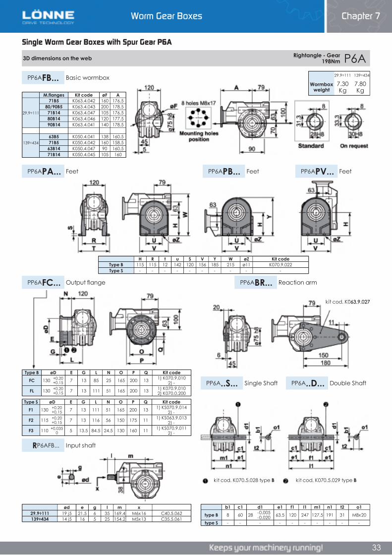
Worm Gear Boxes Chapter 7
33
Single Worm Gear Boxes with Spur Gear P6A
3D dimensions on the web Rightangle - Gear 198Nm P6A
PP6AFB... Basic wormbox
PP6APB... FeetPP6APA... Feet PP6APV... Feet
PP6AFC... Output flange PP6ABR... Reaction arm
PP6A..S... Single Shaft PP6A..D... Double Shaft
RP6AFB... Input shaft
29.9÷111 139÷434
Wormboxweight
7.30Kg
7.80Kg
Type B øD E G L N O P Q Kit codeFC 130 +0,20
+0,15 7 13 85 25 165 200 13 1) K070.9.010 2) -
FL 130 +0,20+0,15 7 13 111 51 165 200 13 1) K070.9.010
2) K070.0.200
Type S øD E G L N O P Q Kit codeF1 130 +0,20
+0,15 7 13 111 51 165 200 13 1) KS070.9.014 2) -
F2 115 +0,20+0,15 7 13 116 56 150 175 11 1) KS063.9.013
2) -
F3 110 +0,0350 5 13.5 84.5 24.5 130 160 11 1) KS070.9.011
2) -
b1 c1 d1 e1 f1 l1 m1 n1 t2 o1type B 8 60 28 -0,005
-0,020 63.5 120 247 127.5 191 31 M8x20
type S - - - - - - - - - -
M.flanges Kit code øF A71B5 K063.4.042 160 176,5
80/90B5 K063.4.043 200 178,529.9÷111 71B14 K063.4.047 105 176,5
80B14 K063.4.046 120 177,590B14 K063.4.041 140 178,5
63B5 K050.4.041 138 160,5139÷434 71B5 K050.4.042 160 158,5
63B14 K050.4.047 90 160,571B14 K050.4.045 105 160
H R t u S V Y W øZ Kit codeType B 115 115 12 142 120 156 185 215 ø11 K070.9.022Type S - - - - - - - - - -
ød e g l m x29.9÷111 19 j5 21.5 6 35 169.4 M6x16 C40.5.062139÷434 14 j5 16 5 25 154.2 M5x13 C35.5.061
kit cod. K070.5.029 type Bkit cod. K070.5.028 type B
kit cod. K063.9.027
Single Worm Gear Boxes with Spur Gear P6A
Chapter 7Worm Gear Boxes
Single Worm Gear Boxes with Spur Gear P6A
3D dimensions on the web Rightangle - Gear 198Nm P6A
PP6AFB... Basic wormbox
PP6APB... FeetPP6APA... Feet PP6APV... Feet
PP6AFC... Output flange PP6ABR... Reaction arm
PP6A..S... Single Shaft PP6A..D... Double Shaft
RP6AFB... Input shaft
29.9÷111 139÷434
Wormboxweight
7.30Kg
7.80Kg
Type B øD E G L N O P Q Kit codeFC 130 +0,20
+0,15 7 13 85 25 165 200 13 1) K070.9.010 2) -
FL 130 +0,20+0,15 7 13 111 51 165 200 13 1) K070.9.010
2) K070.0.200
Type S øD E G L N O P Q Kit codeF1 130 +0,20
+0,15 7 13 111 51 165 200 13 1) KS070.9.014 2) -
F2 115 +0,20+0,15 7 13 116 56 150 175 11 1) KS063.9.013
2) -
F3 110 +0,0350 5 13.5 84.5 24.5 130 160 11 1) KS070.9.011
2) -
b1 c1 d1 e1 f1 l1 m1 n1 t2 o1type B 8 60 28 -0,005
-0,020 63.5 120 247 127.5 191 31 M8x20
type S - - - - - - - - - -
M.flanges Kit code øF A71B5 K063.4.042 160 176,5
80/90B5 K063.4.043 200 178,529.9÷111 71B14 K063.4.047 105 176,5
80B14 K063.4.046 120 177,590B14 K063.4.041 140 178,5
63B5 K050.4.041 138 160,5139÷434 71B5 K050.4.042 160 158,5
63B14 K050.4.047 90 160,571B14 K050.4.045 105 160
H R t u S V Y W øZ Kit codeType B 115 115 12 142 120 156 185 215 ø11 K070.9.022Type S - - - - - - - - - -
ød e g l m x29.9÷111 19 j5 21.5 6 35 169.4 M6x16 C40.5.062139÷434 14 j5 16 5 25 154.2 M5x13 C35.5.061
kit cod. K070.5.029 type Bkit cod. K070.5.028 type B
kit cod. K063.9.027
33
3D dimensions on the web Rightangle - Gear 198Nm P6A
PP6AFB... Basic wormbox
PP6APB... FeetPP6APA... Feet PP6APV... Feet
PP6AFC... Output flange PP6ABR... Reaction arm
PP6A..S... Single Shaft PP6A..D... Double Shaft
RP6AFB... Input shaft
29.9÷111 139÷434
Wormboxweight
7.30Kg
7.80Kg
Type B øD E G L N O P Q Kit codeFC 130 +0,20
+0,15 7 13 85 25 165 200 13 1) K070.9.010 2) -
FL 130 +0,20+0,15 7 13 111 51 165 200 13 1) K070.9.010
2) K070.0.200
Type S øD E G L N O P Q Kit codeF1 130 +0,20
+0,15 7 13 111 51 165 200 13 1) KS070.9.014 2) -
F2 115 +0,20+0,15 7 13 116 56 150 175 11 1) KS063.9.013
2) -
F3 110 +0,0350 5 13.5 84.5 24.5 130 160 11 1) KS070.9.011
2) -
b1 c1 d1 e1 f1 l1 m1 n1 t2 o1type B 8 60 28 -0,005
-0,020 63.5 120 247 127.5 191 31 M8x20
type S - - - - - - - - - -
M.flanges Kit code øF A71B5 K063.4.042 160 176,5
80/90B5 K063.4.043 200 178,529.9÷111 71B14 K063.4.047 105 176,5
80B14 K063.4.046 120 177,590B14 K063.4.041 140 178,5
63B5 K050.4.041 138 160,5139÷434 71B5 K050.4.042 160 158,5
63B14 K050.4.047 90 160,571B14 K050.4.045 105 160
H R t u S V Y W øZ Kit codeType B 115 115 12 142 120 156 185 215 ø11 K070.9.022Type S - - - - - - - - - -
ød e g l m x29.9÷111 19 j5 21.5 6 35 169.4 M6x16 C40.5.062139÷434 14 j5 16 5 25 154.2 M5x13 C35.5.061
kit cod. K070.5.029 type Bkit cod. K070.5.028 type B
kit cod. K063.9.027
Worm Gear Boxes Chapter 7
33
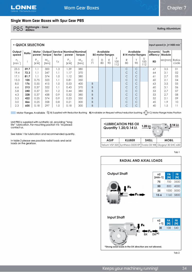
Worm Gear Boxes Chapter 7
34
Single Worm Gear Boxes with Spur Gear P85
P85 Rightangle - Gear 400Nm Rating Alluminium
AGIP KLUBER SHELL MOBILTelium VSF 320 Syntheso D220 EP Tivela Oil WB Glygoyl 30 SHC 630
RADIAL AND AXIAL LOADS
n2[min-1]
FA[N]
FR[N]
1400 108 540
n2[min-1]
FA[N]
FR[N]
75 700 350050 800 400025 1000 5000
15-6 1160 5800
• QUICK SELECTION input speed (n 1)=1400 min-1
Outputspeed Ratio Motor
powerOutputtorque
Servicefactor
Nominalpower
Nominaltorque
AvailableB5 motor flanges
AvailableB14 motor flanges
Dynamiceffiency
ToothModule
n2
[min-1] i P1M
[kW]M2M
[Nm] f.s P1R
[kW]M2R
[Nm]C71
D80
E90
F100112
R80
T90
U100112
RD Mn [mm] Ratioscode
23.5 59.7 1.1 300 1.3 1.39 380 C C 67 3.5 0119.4 72.3 1.1 347 1.1 1.17 370 C C 64 3.1 0217.1 81.7 1.1 374 1.0 1.12 380 C C 61 2.7 0313.3 105 0.75 323 1.1 0.81 350 C C 60 2.1 048.0 176 0.55 415 1.0 0.53 400 B C C 63 3.5 056.6 213 0.37 322 1.1 0.43 370 B C C 60 3.1 065.8 240 0.37 321 1.2 0.44 380 B C C 53 2.7 074.3 328 0.37 438 0.9 0.32 380 B C C 53 2.7 083.3 422 0.25 374 0.9 0.23 350 B C C 52 2.1 093.0 466 0.25 358 0.8 0.21 300 B C C 45 1.9 102.3 605 0.18 297 1.0 0.18 300 B C C 40 1.5 11
Unit P85 is supplied with synthetic oil, providing “long life” lubrication. For mounting position V5- V6 please contact us.
See table 1 for lubrication and recommended quantity.
In table 2 please see possible radial loads and axial loads on the gearbox.
•LUBRICATION P85 Oil Quantity 1.20/0.14 Lt.
Tab 2
Tab 1
Input Shaft
Output Shaft
*Strong axial loads in the DX direction are not allowed.
B) Supplied with Reduction Bushing B) Available on Request without reduction bushing C) Motor Flange Holes PositionMotor Flanges Available
Single Worm Gear Boxes with Spur Gear P85
Chapter 7Worm Gear Boxes
Single Worm Gear Boxes with Spur Gear P85
P85 Rightangle - Gear 400Nm Rating Alluminium
AGIP KLUBER SHELL MOBILTelium VSF 320 Syntheso D220 EP Tivela Oil WB Glygoyl 30 SHC 630
RADIAL AND AXIAL LOADS
n2[min-1]
FA[N]
FR[N]
1400 108 540
n2[min-1]
FA[N]
FR[N]
75 700 350050 800 400025 1000 5000
15-6 1160 5800
• QUICK SELECTION input speed (n 1)=1400 min-1
Outputspeed Ratio Motor
powerOutputtorque
Servicefactor
Nominalpower
Nominaltorque
AvailableB5 motor flanges
AvailableB14 motor flanges
Dynamiceffiency
ToothModule
n2
[min-1] i P1M
[kW]M2M
[Nm] f.s P1R
[kW]M2R
[Nm]C71
D80
E90
F100112
R80
T90
U100112
RD Mn [mm] Ratioscode
23.5 59.7 1.1 300 1.3 1.39 380 C C 67 3.5 0119.4 72.3 1.1 347 1.1 1.17 370 C C 64 3.1 0217.1 81.7 1.1 374 1.0 1.12 380 C C 61 2.7 0313.3 105 0.75 323 1.1 0.81 350 C C 60 2.1 048.0 176 0.55 415 1.0 0.53 400 B C C 63 3.5 056.6 213 0.37 322 1.1 0.43 370 B C C 60 3.1 065.8 240 0.37 321 1.2 0.44 380 B C C 53 2.7 074.3 328 0.37 438 0.9 0.32 380 B C C 53 2.7 083.3 422 0.25 374 0.9 0.23 350 B C C 52 2.1 093.0 466 0.25 358 0.8 0.21 300 B C C 45 1.9 102.3 605 0.18 297 1.0 0.18 300 B C C 40 1.5 11
Unit P85 is supplied with synthetic oil, providing “long life” lubrication. For mounting position V5- V6 please contact us.
See table 1 for lubrication and recommended quantity.
In table 2 please see possible radial loads and axial loads on the gearbox.
•LUBRICATION P85 Oil Quantity 1.20/0.14 Lt.
Tab 2
Tab 1
Input Shaft
Output Shaft
*Strong axial loads in the DX direction are not allowed.
B) Supplied with Reduction Bushing B) Available on Request without reduction bushing C) Motor Flange Holes PositionMotor Flanges Available
34
P85 Rightangle - Gear 400Nm Rating Alluminium
AGIP KLUBER SHELL MOBILTelium VSF 320 Syntheso D220 EP Tivela Oil WB Glygoyl 30 SHC 630
RADIAL AND AXIAL LOADS
n2[min-1]
FA[N]
FR[N]
1400 108 540
n2[min-1]
FA[N]
FR[N]
75 700 350050 800 400025 1000 5000
15-6 1160 5800
• QUICK SELECTION input speed (n 1)=1400 min-1
Outputspeed Ratio Motor
powerOutputtorque
Servicefactor
Nominalpower
Nominaltorque
AvailableB5 motor flanges
AvailableB14 motor flanges
Dynamiceffiency
ToothModule
n2
[min-1] i P1M
[kW]M2M
[Nm] f.s P1R
[kW]M2R
[Nm]C71
D80
E90
F100112
R80
T90
U100112
RD Mn [mm] Ratioscode
23.5 59.7 1.1 300 1.3 1.39 380 C C 67 3.5 0119.4 72.3 1.1 347 1.1 1.17 370 C C 64 3.1 0217.1 81.7 1.1 374 1.0 1.12 380 C C 61 2.7 0313.3 105 0.75 323 1.1 0.81 350 C C 60 2.1 048.0 176 0.55 415 1.0 0.53 400 B C C 63 3.5 056.6 213 0.37 322 1.1 0.43 370 B C C 60 3.1 065.8 240 0.37 321 1.2 0.44 380 B C C 53 2.7 074.3 328 0.37 438 0.9 0.32 380 B C C 53 2.7 083.3 422 0.25 374 0.9 0.23 350 B C C 52 2.1 093.0 466 0.25 358 0.8 0.21 300 B C C 45 1.9 102.3 605 0.18 297 1.0 0.18 300 B C C 40 1.5 11
Unit P85 is supplied with synthetic oil, providing “long life” lubrication. For mounting position V5- V6 please contact us.
See table 1 for lubrication and recommended quantity.
In table 2 please see possible radial loads and axial loads on the gearbox.
•LUBRICATION P85 Oil Quantity 1.20/0.14 Lt.
Tab 2
Tab 1
Input Shaft
Output Shaft
*Strong axial loads in the DX direction are not allowed.
B) Supplied with Reduction Bushing B) Available on Request without reduction bushing C) Motor Flange Holes PositionMotor Flanges Available
Worm Gear Boxes Chapter 7
34

Worm Gear Boxes Chapter 7
35
Single Worm Gear Boxes with Spur Gear P85
3D dimensions on the web Rightangle - Gear 400Nm P85
PP85FB... Basic wormbox
PP85PB... FeetPP85PA... Feet PP85PV... Feet
PP85FC... Output flange PP85BR... Reaction arm
PP85..S... Single Shaft PP85..D... Double Shaft
RP85FB... Input shaft
Wormboxweight 19.30 kg
Type B øD E G L N O P Q Kit codeFC 152 +0,06
+0,00 5 16 108 40.5 176 205 13 1) K085.9.010 2) -
FL 152 +0,06+0,00 5 16 148.5 81 176 205 13 1) K085.9.010
2) K085.0.201
Type S øD E G L N O P Q Kit codeF1 130 +0,04
+0,00 5 13 117.5 50 165 200 11.5 1) KS085.9.012 2) -
F2 152 +0,06+0,00 5 15 147.5 80 180 205 12.5 1) KS085.9.013
2) -
F3 130 +0,04+0,00 5 13 106.5 39 165 200 13 1) KS085.9.015
2) -
b1 c1 d1 e1 f1 l1 m1 n1 t2 o1type B 10 60 35 -0,005
-0,020 73.5 135 282 141 214.5 38 M10x23
type S - - - - - - - - - -
M. flanges Kit.code øF A63B5 K063.4.041 140 195.271B5 K063.4.042 160 193.2
80/90B5 K063.4.043 200 195.2
71B14 K063.4.047 105 193.280B14 K063.4.046 120 194.290B14 K063.4.041 140 195.2
H R t u S V Y W øZ Kit codeType B 142 145 5 182 140 180 236.5 280 ø10.5 K085.9.022Type S - - - - - - - - - -
ød e g l m xtype B 19 j5 21.5 6 35 187.5 M6x16 C40.5.062type S - - - - - -
kit cod. K085.5.029 type Bkit cod. K085.5.028 type B
kit cod. K085.9.027
Single Worm Gear Boxes with Spur Gear P85
Chapter 7Worm Gear Boxes
Single Worm Gear Boxes with Spur Gear P85
3D dimensions on the web Rightangle - Gear 400Nm P85
PP85FB... Basic wormbox
PP85PB... FeetPP85PA... Feet PP85PV... Feet
PP85FC... Output flange PP85BR... Reaction arm
PP85..S... Single Shaft PP85..D... Double Shaft
RP85FB... Input shaft
Wormboxweight 19.30 kg
Type B øD E G L N O P Q Kit codeFC 152 +0,06
+0,00 5 16 108 40.5 176 205 13 1) K085.9.010 2) -
FL 152 +0,06+0,00 5 16 148.5 81 176 205 13 1) K085.9.010
2) K085.0.201
Type S øD E G L N O P Q Kit codeF1 130 +0,04
+0,00 5 13 117.5 50 165 200 11.5 1) KS085.9.012 2) -
F2 152 +0,06+0,00 5 15 147.5 80 180 205 12.5 1) KS085.9.013
2) -
F3 130 +0,04+0,00 5 13 106.5 39 165 200 13 1) KS085.9.015
2) -
b1 c1 d1 e1 f1 l1 m1 n1 t2 o1type B 10 60 35 -0,005
-0,020 73.5 135 282 141 214.5 38 M10x23
type S - - - - - - - - - -
M. flanges Kit.code øF A63B5 K063.4.041 140 195.271B5 K063.4.042 160 193.2
80/90B5 K063.4.043 200 195.2
71B14 K063.4.047 105 193.280B14 K063.4.046 120 194.290B14 K063.4.041 140 195.2
H R t u S V Y W øZ Kit codeType B 142 145 5 182 140 180 236.5 280 ø10.5 K085.9.022Type S - - - - - - - - - -
ød e g l m xtype B 19 j5 21.5 6 35 187.5 M6x16 C40.5.062type S - - - - - -
kit cod. K085.5.029 type Bkit cod. K085.5.028 type B
kit cod. K085.9.027
35
3D dimensions on the web Rightangle - Gear 400Nm P85
PP85FB... Basic wormbox
PP85PB... FeetPP85PA... Feet PP85PV... Feet
PP85FC... Output flange PP85BR... Reaction arm
PP85..S... Single Shaft PP85..D... Double Shaft
RP85FB... Input shaft
Wormboxweight 19.30 kg
Type B øD E G L N O P Q Kit codeFC 152 +0,06
+0,00 5 16 108 40.5 176 205 13 1) K085.9.010 2) -
FL 152 +0,06+0,00 5 16 148.5 81 176 205 13 1) K085.9.010
2) K085.0.201
Type S øD E G L N O P Q Kit codeF1 130 +0,04
+0,00 5 13 117.5 50 165 200 11.5 1) KS085.9.012 2) -
F2 152 +0,06+0,00 5 15 147.5 80 180 205 12.5 1) KS085.9.013
2) -
F3 130 +0,04+0,00 5 13 106.5 39 165 200 13 1) KS085.9.015
2) -
b1 c1 d1 e1 f1 l1 m1 n1 t2 o1type B 10 60 35 -0,005
-0,020 73.5 135 282 141 214.5 38 M10x23
type S - - - - - - - - - -
M. flanges Kit.code øF A63B5 K063.4.041 140 195.271B5 K063.4.042 160 193.2
80/90B5 K063.4.043 200 195.2
71B14 K063.4.047 105 193.280B14 K063.4.046 120 194.290B14 K063.4.041 140 195.2
H R t u S V Y W øZ Kit codeType B 142 145 5 182 140 180 236.5 280 ø10.5 K085.9.022Type S - - - - - - - - - -
ød e g l m xtype B 19 j5 21.5 6 35 187.5 M6x16 C40.5.062type S - - - - - -
kit cod. K085.5.029 type Bkit cod. K085.5.028 type B
kit cod. K085.9.027
Worm Gear Boxes Chapter 7
35
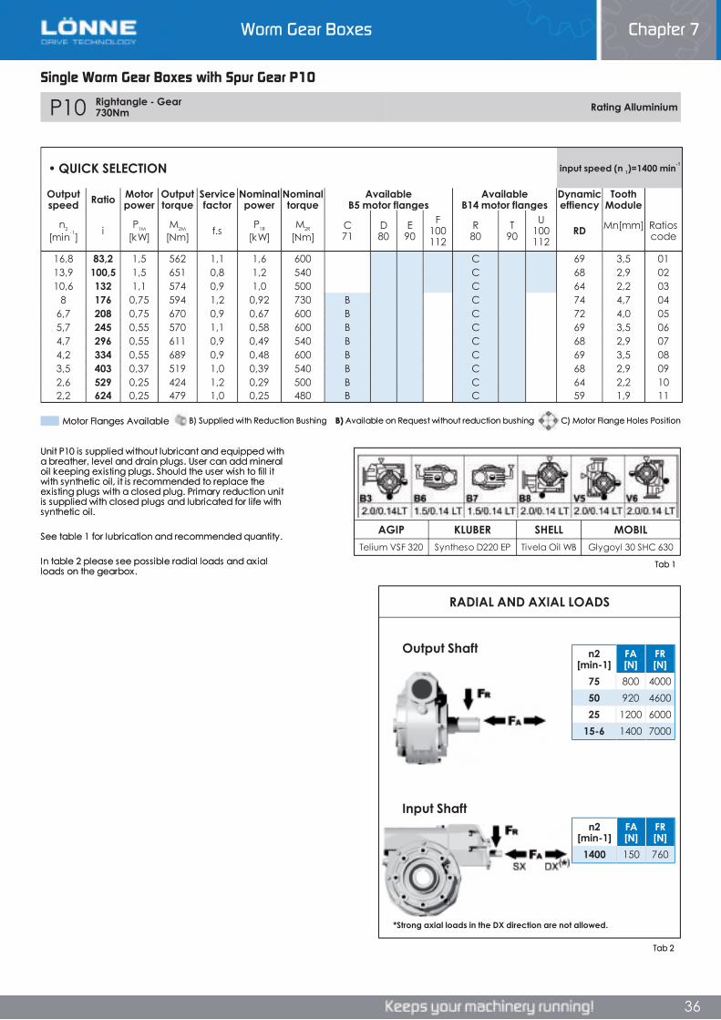
Worm Gear Boxes Chapter 7
36
Single Worm Gear Boxes with Spur Gear P10
P10 Rightangle - Gear 730Nm Rating Alluminium
AGIP KLUBER SHELL MOBILTelium VSF 320 Syntheso D220 EP Tivela Oil WB Glygoyl 30 SHC 630
RADIAL AND AXIAL LOADS
n2[min-1]
FA[N]
FR[N]
1400 150 760
n2[min-1]
FA[N]
FR[N]
75 800 400050 920 460025 1200 6000
15-6 1400 7000
• QUICK SELECTION input speed (n 1)=1400 min-1
Outputspeed Ratio Motor
powerOutputtorque
Servicefactor
Nominalpower
Nominaltorque
AvailableB5 motor flanges
AvailableB14 motor flanges
Dynamiceffiency
ToothModule
n2
[min-1] i P1M
[kW]M2M
[Nm] f.s P1R
[kW]M2R
[Nm]C71
D80
E90
F100112
R80
T90
U100112
RD Mn [mm] Ratioscode
16,8 83,2 1,5 562 1,1 1,6 600 C 69 3,5 0113,9 100,5 1,5 651 0,8 1,2 540 C 68 2,9 0210,6 132 1,1 574 0,9 1,0 500 C 64 2,2 03
8 176 0,75 594 1,2 0,92 730 B C 74 4,7 046,7 208 0,75 670 0,9 0,67 600 B C 72 4,0 055,7 245 0,55 570 1,1 0,58 600 B C 69 3,5 064,7 296 0,55 611 0,9 0,49 540 B C 68 2,9 074,2 334 0,55 689 0,9 0,48 600 B C 69 3,5 083,5 403 0,37 519 1,0 0,39 540 B C 68 2,9 092,6 529 0,25 424 1,2 0,29 500 B C 64 2,2 102,2 624 0,25 479 1,0 0,25 480 B C 59 1,9 11
Unit P10 is supplied without lubricant and equipped with a breather, level and drain plugs. User can add mineral oil keeping existing plugs. Should the user wish to fill it with synthetic oil, it is recommended to replace the existing plugs with a closed plug. Primary reduction unit is supplied with closed plugs and lubricated for life with synthetic oil.
See table 1 for lubrication and recommended quantity.
In table 2 please see possible radial loads and axial loads on the gearbox.
Tab 2
Tab 1
Input Shaft
Output Shaft
*Strong axial loads in the DX direction are not allowed.
Motor Flanges Available C) Motor Flange Holes PositionB) Available on Request without reduction bushingB) Supplied with Reduction Bushing
Single Worm Gear Boxes with Spur Gear P10
Chapter 7Worm Gear Boxes
36
P10 Rightangle - Gear 730Nm Rating Alluminium
AGIP KLUBER SHELL MOBILTelium VSF 320 Syntheso D220 EP Tivela Oil WB Glygoyl 30 SHC 630
RADIAL AND AXIAL LOADS
n2[min-1]
FA[N]
FR[N]
1400 150 760
n2[min-1]
FA[N]
FR[N]
75 800 400050 920 460025 1200 6000
15-6 1400 7000
• QUICK SELECTION input speed (n 1)=1400 min-1
Outputspeed Ratio Motor
powerOutputtorque
Servicefactor
Nominalpower
Nominaltorque
AvailableB5 motor flanges
AvailableB14 motor flanges
Dynamiceffiency
ToothModule
n2
[min-1] i P1M
[kW]M2M
[Nm] f.s P1R
[kW]M2R
[Nm]C71
D80
E90
F100112
R80
T90
U100112
RD Mn [mm] Ratioscode
16,8 83,2 1,5 562 1,1 1,6 600 C 69 3,5 0113,9 100,5 1,5 651 0,8 1,2 540 C 68 2,9 0210,6 132 1,1 574 0,9 1,0 500 C 64 2,2 03
8 176 0,75 594 1,2 0,92 730 B C 74 4,7 046,7 208 0,75 670 0,9 0,67 600 B C 72 4,0 055,7 245 0,55 570 1,1 0,58 600 B C 69 3,5 064,7 296 0,55 611 0,9 0,49 540 B C 68 2,9 074,2 334 0,55 689 0,9 0,48 600 B C 69 3,5 083,5 403 0,37 519 1,0 0,39 540 B C 68 2,9 092,6 529 0,25 424 1,2 0,29 500 B C 64 2,2 102,2 624 0,25 479 1,0 0,25 480 B C 59 1,9 11
Unit P10 is supplied without lubricant and equipped with a breather, level and drain plugs. User can add mineral oil keeping existing plugs. Should the user wish to fill it with synthetic oil, it is recommended to replace the existing plugs with a closed plug. Primary reduction unit is supplied with closed plugs and lubricated for life with synthetic oil.
See table 1 for lubrication and recommended quantity.
In table 2 please see possible radial loads and axial loads on the gearbox.
Tab 2
Tab 1
Input Shaft
Output Shaft
*Strong axial loads in the DX direction are not allowed.
Motor Flanges Available C) Motor Flange Holes PositionB) Available on Request without reduction bushingB) Supplied with Reduction Bushing
Worm Gear Boxes Chapter 7
36
Worm Gear Boxes Chapter 7
37
Single Worm Gear Boxes with Spur Gear P10
3D dimensions on the web Rightangle - Gear 730Nm P10
Wormboxweight 41.00 kgPP10FB... Basic wormbox
PP10PB... FeetPP10PA... Feet PP10PV... Feet
PP10FC... Output flange PP10BR... Reaction arm
PP10..S... Single Shaft PP10..D... Double Shaft
RP10FB... Input shaft
Type B øD E G L N O P Q Kit codeFC 170 +0,083
+0,043 11 16.5 131.5 54 230 270 13 1) K110.9.010 2) -
FL 170 +0,083+0,043 11 16.5 179.5 102 230 270 13 1) K110.9.011
2) -
Type S øD E G L N O P Q Kit codeF1 180 +0,040
0 5 18 150 72.5 215 250 15 1) KS110.9.014 2) -
F2 170 +0,083+0,043 9.5 15 178 100.5 230 270 13 1) KS110.9.012
2) -
F3 180 +0,0400 5 18 130 52.5 215 250 15 1) KS110.9.013
2) -
b1 c1 d1 e1 f1 l1 m1 n1 t2 o1type B 12 75 42 -0,005
-0,020 96.5 155 348 163.5 260 45 M12x32
type S - - - - - - - - - -
M. flanges Kit.code øF A63B5 K063.4.041 140 214.771B5 K063.4.042 160 212.7
80/90B5 K063.4.043 200 214.7
71B14 K063.4.047 105 212.780B14 K063.4.046 120 213.790B14 K063.4.041 140 214.7
H R S T U V Y W øZ kit codeType B 170 180 22 224 200 240 286 333 ø13 K110.9.022Type S 172 160 18 190 200 240 288 335 ø14 K110.9.023
ød e g l m xtype B 19 j5 21.5 6 35 205 M6x16 C40.5.062type S - - - - - -
kit cod. K110.9.027
kit cod. K110.5.029 type Bkit cod. K110.5.028 type B
Single Worm Gear Boxes with Spur Gear P10
Chapter 7Worm Gear Boxes
Single Worm Gear Boxes with Spur Gear P10
3D dimensions on the web Rightangle - Gear 730Nm P10
Wormboxweight 41.00 kgPP10FB... Basic wormbox
PP10PB... FeetPP10PA... Feet PP10PV... Feet
PP10FC... Output flange PP10BR... Reaction arm
PP10..S... Single Shaft PP10..D... Double Shaft
RP10FB... Input shaft
Type B øD E G L N O P Q Kit codeFC 170 +0,083
+0,043 11 16.5 131.5 54 230 270 13 1) K110.9.010 2) -
FL 170 +0,083+0,043 11 16.5 179.5 102 230 270 13 1) K110.9.011
2) -
Type S øD E G L N O P Q Kit codeF1 180 +0,040
0 5 18 150 72.5 215 250 15 1) KS110.9.014 2) -
F2 170 +0,083+0,043 9.5 15 178 100.5 230 270 13 1) KS110.9.012
2) -
F3 180 +0,0400 5 18 130 52.5 215 250 15 1) KS110.9.013
2) -
b1 c1 d1 e1 f1 l1 m1 n1 t2 o1type B 12 75 42 -0,005
-0,020 96.5 155 348 163.5 260 45 M12x32
type S - - - - - - - - - -
M. flanges Kit.code øF A63B5 K063.4.041 140 214.771B5 K063.4.042 160 212.7
80/90B5 K063.4.043 200 214.7
71B14 K063.4.047 105 212.780B14 K063.4.046 120 213.790B14 K063.4.041 140 214.7
H R S T U V Y W øZ kit codeType B 170 180 22 224 200 240 286 333 ø13 K110.9.022Type S 172 160 18 190 200 240 288 335 ø14 K110.9.023
ød e g l m xtype B 19 j5 21.5 6 35 205 M6x16 C40.5.062type S - - - - - -
kit cod. K110.9.027
kit cod. K110.5.029 type Bkit cod. K110.5.028 type B
37
3D dimensions on the web Rightangle - Gear 730Nm P10
Wormboxweight 41.00 kgPP10FB... Basic wormbox
PP10PB... FeetPP10PA... Feet PP10PV... Feet
PP10FC... Output flange PP10BR... Reaction arm
PP10..S... Single Shaft PP10..D... Double Shaft
RP10FB... Input shaft
Type B øD E G L N O P Q Kit codeFC 170 +0,083
+0,043 11 16.5 131.5 54 230 270 13 1) K110.9.010 2) -
FL 170 +0,083+0,043 11 16.5 179.5 102 230 270 13 1) K110.9.011
2) -
Type S øD E G L N O P Q Kit codeF1 180 +0,040
0 5 18 150 72.5 215 250 15 1) KS110.9.014 2) -
F2 170 +0,083+0,043 9.5 15 178 100.5 230 270 13 1) KS110.9.012
2) -
F3 180 +0,0400 5 18 130 52.5 215 250 15 1) KS110.9.013
2) -
b1 c1 d1 e1 f1 l1 m1 n1 t2 o1type B 12 75 42 -0,005
-0,020 96.5 155 348 163.5 260 45 M12x32
type S - - - - - - - - - -
M. flanges Kit.code øF A63B5 K063.4.041 140 214.771B5 K063.4.042 160 212.7
80/90B5 K063.4.043 200 214.7
71B14 K063.4.047 105 212.780B14 K063.4.046 120 213.790B14 K063.4.041 140 214.7
H R S T U V Y W øZ kit codeType B 170 180 22 224 200 240 286 333 ø13 K110.9.022Type S 172 160 18 190 200 240 288 335 ø14 K110.9.023
ød e g l m xtype B 19 j5 21.5 6 35 205 M6x16 C40.5.062type S - - - - - -
kit cod. K110.9.027
kit cod. K110.5.029 type Bkit cod. K110.5.028 type B
Worm Gear Boxes Chapter 7
37
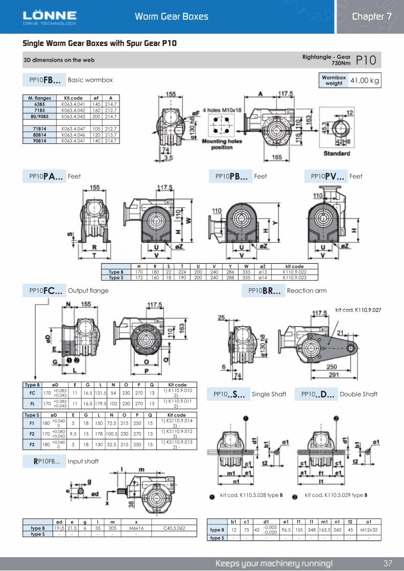
Worm Gear Boxes Chapter 7
36
Single Worm Gear Boxes with Spur Gear P10
P10 Rightangle - Gear 730Nm Rating Alluminium
AGIP KLUBER SHELL MOBILTelium VSF 320 Syntheso D220 EP Tivela Oil WB Glygoyl 30 SHC 630
RADIAL AND AXIAL LOADS
n2[min-1]
FA[N]
FR[N]
1400 150 760
n2[min-1]
FA[N]
FR[N]
75 800 400050 920 460025 1200 6000
15-6 1400 7000
• QUICK SELECTION input speed (n 1)=1400 min-1
Outputspeed Ratio Motor
powerOutputtorque
Servicefactor
Nominalpower
Nominaltorque
AvailableB5 motor flanges
AvailableB14 motor flanges
Dynamiceffiency
ToothModule
n2
[min-1] i P1M
[kW]M2M
[Nm] f.s P1R
[kW]M2R
[Nm]C71
D80
E90
F100112
R80
T90
U100112
RD Mn [mm] Ratioscode
16,8 83,2 1,5 562 1,1 1,6 600 C 69 3,5 0113,9 100,5 1,5 651 0,8 1,2 540 C 68 2,9 0210,6 132 1,1 574 0,9 1,0 500 C 64 2,2 03
8 176 0,75 594 1,2 0,92 730 B C 74 4,7 046,7 208 0,75 670 0,9 0,67 600 B C 72 4,0 055,7 245 0,55 570 1,1 0,58 600 B C 69 3,5 064,7 296 0,55 611 0,9 0,49 540 B C 68 2,9 074,2 334 0,55 689 0,9 0,48 600 B C 69 3,5 083,5 403 0,37 519 1,0 0,39 540 B C 68 2,9 092,6 529 0,25 424 1,2 0,29 500 B C 64 2,2 102,2 624 0,25 479 1,0 0,25 480 B C 59 1,9 11
Unit P10 is supplied without lubricant and equipped with a breather, level and drain plugs. User can add mineral oil keeping existing plugs. Should the user wish to fill it with synthetic oil, it is recommended to replace the existing plugs with a closed plug. Primary reduction unit is supplied with closed plugs and lubricated for life with synthetic oil.
See table 1 for lubrication and recommended quantity.
In table 2 please see possible radial loads and axial loads on the gearbox.
Tab 2
Tab 1
Input Shaft
Output Shaft
*Strong axial loads in the DX direction are not allowed.
Motor Flanges Available C) Motor Flange Holes PositionB) Available on Request without reduction bushingB) Supplied with Reduction Bushing
Single Worm Gear Boxes with Spur Gear P10
Chapter 7Worm Gear Boxes
36
P10 Rightangle - Gear 730Nm Rating Alluminium
AGIP KLUBER SHELL MOBILTelium VSF 320 Syntheso D220 EP Tivela Oil WB Glygoyl 30 SHC 630
RADIAL AND AXIAL LOADS
n2[min-1]
FA[N]
FR[N]
1400 150 760
n2[min-1]
FA[N]
FR[N]
75 800 400050 920 460025 1200 6000
15-6 1400 7000
• QUICK SELECTION input speed (n 1)=1400 min-1
Outputspeed Ratio Motor
powerOutputtorque
Servicefactor
Nominalpower
Nominaltorque
AvailableB5 motor flanges
AvailableB14 motor flanges
Dynamiceffiency
ToothModule
n2
[min-1] i P1M
[kW]M2M
[Nm] f.s P1R
[kW]M2R
[Nm]C71
D80
E90
F100112
R80
T90
U100112
RD Mn [mm] Ratioscode
16,8 83,2 1,5 562 1,1 1,6 600 C 69 3,5 0113,9 100,5 1,5 651 0,8 1,2 540 C 68 2,9 0210,6 132 1,1 574 0,9 1,0 500 C 64 2,2 03
8 176 0,75 594 1,2 0,92 730 B C 74 4,7 046,7 208 0,75 670 0,9 0,67 600 B C 72 4,0 055,7 245 0,55 570 1,1 0,58 600 B C 69 3,5 064,7 296 0,55 611 0,9 0,49 540 B C 68 2,9 074,2 334 0,55 689 0,9 0,48 600 B C 69 3,5 083,5 403 0,37 519 1,0 0,39 540 B C 68 2,9 092,6 529 0,25 424 1,2 0,29 500 B C 64 2,2 102,2 624 0,25 479 1,0 0,25 480 B C 59 1,9 11
Unit P10 is supplied without lubricant and equipped with a breather, level and drain plugs. User can add mineral oil keeping existing plugs. Should the user wish to fill it with synthetic oil, it is recommended to replace the existing plugs with a closed plug. Primary reduction unit is supplied with closed plugs and lubricated for life with synthetic oil.
See table 1 for lubrication and recommended quantity.
In table 2 please see possible radial loads and axial loads on the gearbox.
Tab 2
Tab 1
Input Shaft
Output Shaft
*Strong axial loads in the DX direction are not allowed.
Motor Flanges Available C) Motor Flange Holes PositionB) Available on Request without reduction bushingB) Supplied with Reduction Bushing
Worm Gear Boxes Chapter 7
36
Worm Gear Boxes Chapter 7
37
Single Worm Gear Boxes with Spur Gear P10
3D dimensions on the web Rightangle - Gear 730Nm P10
Wormboxweight 41.00 kgPP10FB... Basic wormbox
PP10PB... FeetPP10PA... Feet PP10PV... Feet
PP10FC... Output flange PP10BR... Reaction arm
PP10..S... Single Shaft PP10..D... Double Shaft
RP10FB... Input shaft
Type B øD E G L N O P Q Kit codeFC 170 +0,083
+0,043 11 16.5 131.5 54 230 270 13 1) K110.9.010 2) -
FL 170 +0,083+0,043 11 16.5 179.5 102 230 270 13 1) K110.9.011
2) -
Type S øD E G L N O P Q Kit codeF1 180 +0,040
0 5 18 150 72.5 215 250 15 1) KS110.9.014 2) -
F2 170 +0,083+0,043 9.5 15 178 100.5 230 270 13 1) KS110.9.012
2) -
F3 180 +0,0400 5 18 130 52.5 215 250 15 1) KS110.9.013
2) -
b1 c1 d1 e1 f1 l1 m1 n1 t2 o1type B 12 75 42 -0,005
-0,020 96.5 155 348 163.5 260 45 M12x32
type S - - - - - - - - - -
M. flanges Kit.code øF A63B5 K063.4.041 140 214.771B5 K063.4.042 160 212.7
80/90B5 K063.4.043 200 214.7
71B14 K063.4.047 105 212.780B14 K063.4.046 120 213.790B14 K063.4.041 140 214.7
H R S T U V Y W øZ kit codeType B 170 180 22 224 200 240 286 333 ø13 K110.9.022Type S 172 160 18 190 200 240 288 335 ø14 K110.9.023
ød e g l m xtype B 19 j5 21.5 6 35 205 M6x16 C40.5.062type S - - - - - -
kit cod. K110.9.027
kit cod. K110.5.029 type Bkit cod. K110.5.028 type B
Single Worm Gear Boxes with Spur Gear P10
Chapter 7Worm Gear Boxes
Single Worm Gear Boxes with Spur Gear P10
3D dimensions on the web Rightangle - Gear 730Nm P10
Wormboxweight 41.00 kgPP10FB... Basic wormbox
PP10PB... FeetPP10PA... Feet PP10PV... Feet
PP10FC... Output flange PP10BR... Reaction arm
PP10..S... Single Shaft PP10..D... Double Shaft
RP10FB... Input shaft
Type B øD E G L N O P Q Kit codeFC 170 +0,083
+0,043 11 16.5 131.5 54 230 270 13 1) K110.9.010 2) -
FL 170 +0,083+0,043 11 16.5 179.5 102 230 270 13 1) K110.9.011
2) -
Type S øD E G L N O P Q Kit codeF1 180 +0,040
0 5 18 150 72.5 215 250 15 1) KS110.9.014 2) -
F2 170 +0,083+0,043 9.5 15 178 100.5 230 270 13 1) KS110.9.012
2) -
F3 180 +0,0400 5 18 130 52.5 215 250 15 1) KS110.9.013
2) -
b1 c1 d1 e1 f1 l1 m1 n1 t2 o1type B 12 75 42 -0,005
-0,020 96.5 155 348 163.5 260 45 M12x32
type S - - - - - - - - - -
M. flanges Kit.code øF A63B5 K063.4.041 140 214.771B5 K063.4.042 160 212.7
80/90B5 K063.4.043 200 214.7
71B14 K063.4.047 105 212.780B14 K063.4.046 120 213.790B14 K063.4.041 140 214.7
H R S T U V Y W øZ kit codeType B 170 180 22 224 200 240 286 333 ø13 K110.9.022Type S 172 160 18 190 200 240 288 335 ø14 K110.9.023
ød e g l m xtype B 19 j5 21.5 6 35 205 M6x16 C40.5.062type S - - - - - -
kit cod. K110.9.027
kit cod. K110.5.029 type Bkit cod. K110.5.028 type B
37
3D dimensions on the web Rightangle - Gear 730Nm P10
Wormboxweight 41.00 kgPP10FB... Basic wormbox
PP10PB... FeetPP10PA... Feet PP10PV... Feet
PP10FC... Output flange PP10BR... Reaction arm
PP10..S... Single Shaft PP10..D... Double Shaft
RP10FB... Input shaft
Type B øD E G L N O P Q Kit codeFC 170 +0,083
+0,043 11 16.5 131.5 54 230 270 13 1) K110.9.010 2) -
FL 170 +0,083+0,043 11 16.5 179.5 102 230 270 13 1) K110.9.011
2) -
Type S øD E G L N O P Q Kit codeF1 180 +0,040
0 5 18 150 72.5 215 250 15 1) KS110.9.014 2) -
F2 170 +0,083+0,043 9.5 15 178 100.5 230 270 13 1) KS110.9.012
2) -
F3 180 +0,0400 5 18 130 52.5 215 250 15 1) KS110.9.013
2) -
b1 c1 d1 e1 f1 l1 m1 n1 t2 o1type B 12 75 42 -0,005
-0,020 96.5 155 348 163.5 260 45 M12x32
type S - - - - - - - - - -
M. flanges Kit.code øF A63B5 K063.4.041 140 214.771B5 K063.4.042 160 212.7
80/90B5 K063.4.043 200 214.7
71B14 K063.4.047 105 212.780B14 K063.4.046 120 213.790B14 K063.4.041 140 214.7
H R S T U V Y W øZ kit codeType B 170 180 22 224 200 240 286 333 ø13 K110.9.022Type S 172 160 18 190 200 240 288 335 ø14 K110.9.023
ød e g l m xtype B 19 j5 21.5 6 35 205 M6x16 C40.5.062type S - - - - - -
kit cod. K110.9.027
kit cod. K110.5.029 type Bkit cod. K110.5.028 type B
Worm Gear Boxes Chapter 7
37

Worm Gear Boxes Chapter 7
38
Combined Worm Gear Unit
303 Rightangle - Gear 030+030 30Nm Rating Alluminium
AGIP KLUBER SHELL MOBILTelium VSF 320 Syntheso D220 EP Tivela Oil WB Glygoyl 30 SHC 630
RADIAL AND AXIAL LOADS
n2[min-1]
FA[N]
FR[N]
1400 20 100
n2[min-1]
FA[N]
FR[N]
25 300 180015 400 2000
• QUICK SELECTION input speed (n 1)=1400 min-1
Outputspeed Ratio Motor
powerOutputtorque
Servicefactor
Nominalpower
Nominaltorque
AvailableB5 motor flanges
AvailableB14 motor flanges
Dynamiceffiency
ToothModule
n2
[min-1] i P1M
[kW]M2M
[Nm] f.s P1R
[kW]M2R
[Nm]A56
B63
O56
P63 RD Mn [mm] Ratios
code
9.3 150 0.06 29 1.0 0.06 30 B B- C 48 1.44 016.7 210 0.06 39 0.8 0.05 30 B B- C 45 1.44 024.7 300 0.06* 30 <0.8 0.04 30 B B- C 36 1.44 033.1 450 0.06* 30 <0.8 0.03 30 B B- C 33 1.44 042.3 600 0.06* 30 <0.8 0.02 30 B B- C 30 1.44 051.6 900 0.06* 30 <0.8 0.02 30 B B- C 27 1.44 061.2 1200 0.06* 30 <0.8 0.01 30 B B- C 26 1.44 070.8 1830 0.06* 30 <0.8 0.01 30 B B- C 24 1.44 080.6 2400 0.06* 30 <0.8 0.01 30 B B- C 22 1.44 09
Unit 303 is supplied with synthetic oil, providing “long life” lubrication. For mounting position V5- V6 please contact us.
See table 1 for lubrication and recommended quantity.
In table 2 please see possible radial loads and axial loads on the gearbox.
Tab 2
Tab 1
LUBRICATION 303 OIL Quantity 0.03/0.3 Lt
Input Shaft
Output Shaft
*Strong axial loads in the DX direction are not allowed.
* Power higher than the maximum one which can be supported by the gearbox. Select according to the torque M2R
Motor Flanges Available C) Motor Flange Holes PositionB) Available on Request without reduction bushingB) Supplied with Reduction Bushing
Combined Worm Gear Unit
Chapter 7Worm Gear Boxes
Combined Worm Gear Unit
303 Rightangle - Gear 030+030 30Nm Rating Alluminium
AGIP KLUBER SHELL MOBILTelium VSF 320 Syntheso D220 EP Tivela Oil WB Glygoyl 30 SHC 630
RADIAL AND AXIAL LOADS
n2[min-1]
FA[N]
FR[N]
1400 20 100
n2[min-1]
FA[N]
FR[N]
25 300 180015 400 2000
• QUICK SELECTION input speed (n 1)=1400 min-1
Outputspeed Ratio Motor
powerOutputtorque
Servicefactor
Nominalpower
Nominaltorque
AvailableB5 motor flanges
AvailableB14 motor flanges
Dynamiceffiency
ToothModule
n2
[min-1] i P1M
[kW]M2M
[Nm] f.s P1R
[kW]M2R
[Nm]A56
B63
O56
P63 RD Mn [mm] Ratios
code
9.3 150 0.06 29 1.0 0.06 30 B B- C 48 1.44 016.7 210 0.06 39 0.8 0.05 30 B B- C 45 1.44 024.7 300 0.06* 30 <0.8 0.04 30 B B- C 36 1.44 033.1 450 0.06* 30 <0.8 0.03 30 B B- C 33 1.44 042.3 600 0.06* 30 <0.8 0.02 30 B B- C 30 1.44 051.6 900 0.06* 30 <0.8 0.02 30 B B- C 27 1.44 061.2 1200 0.06* 30 <0.8 0.01 30 B B- C 26 1.44 070.8 1830 0.06* 30 <0.8 0.01 30 B B- C 24 1.44 080.6 2400 0.06* 30 <0.8 0.01 30 B B- C 22 1.44 09
Unit 303 is supplied with synthetic oil, providing “long life” lubrication. For mounting position V5- V6 please contact us.
See table 1 for lubrication and recommended quantity.
In table 2 please see possible radial loads and axial loads on the gearbox.
Tab 2
Tab 1
LUBRICATION 303 OIL Quantity 0.03/0.3 Lt
Input Shaft
Output Shaft
*Strong axial loads in the DX direction are not allowed.
* Power higher than the maximum one which can be supported by the gearbox. Select according to the torque M2R
Motor Flanges Available C) Motor Flange Holes PositionB) Available on Request without reduction bushingB) Supplied with Reduction Bushing
38
303 Rightangle - Gear 030+030 30Nm Rating Alluminium
AGIP KLUBER SHELL MOBILTelium VSF 320 Syntheso D220 EP Tivela Oil WB Glygoyl 30 SHC 630
RADIAL AND AXIAL LOADS
n2[min-1]
FA[N]
FR[N]
1400 20 100
n2[min-1]
FA[N]
FR[N]
25 300 180015 400 2000
• QUICK SELECTION input speed (n 1)=1400 min-1
Outputspeed Ratio Motor
powerOutputtorque
Servicefactor
Nominalpower
Nominaltorque
AvailableB5 motor flanges
AvailableB14 motor flanges
Dynamiceffiency
ToothModule
n2
[min-1] i P1M
[kW]M2M
[Nm] f.s P1R
[kW]M2R
[Nm]A56
B63
O56
P63 RD Mn [mm] Ratios
code
9.3 150 0.06 29 1.0 0.06 30 B B- C 48 1.44 016.7 210 0.06 39 0.8 0.05 30 B B- C 45 1.44 024.7 300 0.06* 30 <0.8 0.04 30 B B- C 36 1.44 033.1 450 0.06* 30 <0.8 0.03 30 B B- C 33 1.44 042.3 600 0.06* 30 <0.8 0.02 30 B B- C 30 1.44 051.6 900 0.06* 30 <0.8 0.02 30 B B- C 27 1.44 061.2 1200 0.06* 30 <0.8 0.01 30 B B- C 26 1.44 070.8 1830 0.06* 30 <0.8 0.01 30 B B- C 24 1.44 080.6 2400 0.06* 30 <0.8 0.01 30 B B- C 22 1.44 09
Unit 303 is supplied with synthetic oil, providing “long life” lubrication. For mounting position V5- V6 please contact us.
See table 1 for lubrication and recommended quantity.
In table 2 please see possible radial loads and axial loads on the gearbox.
Tab 2
Tab 1
LUBRICATION 303 OIL Quantity 0.03/0.3 Lt
Input Shaft
Output Shaft
*Strong axial loads in the DX direction are not allowed.
* Power higher than the maximum one which can be supported by the gearbox. Select according to the torque M2R
Motor Flanges Available C) Motor Flange Holes PositionB) Available on Request without reduction bushingB) Supplied with Reduction Bushing
Worm Gear Boxes Chapter 7
38
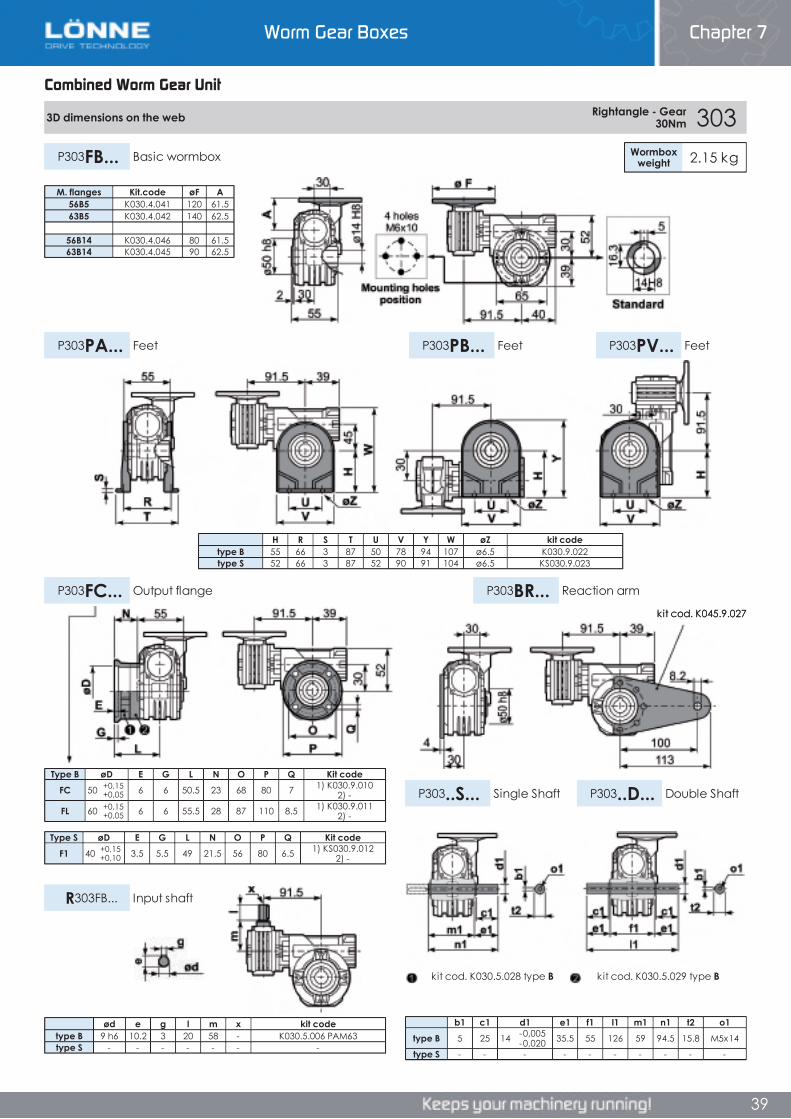
Worm Gear Boxes Chapter 7
39
Combined Worm Gear Unit
3D dimensions on the web Rightangle - Gear 30Nm 303
Wormboxweight 2.15 kgP303FB... Basic wormbox
P303PB... FeetP303PA... Feet P303PV... Feet
P303FC... Output flange P303BR... Reaction arm
P303..S... Single Shaft P303..D... Double Shaft
R303FB... Input shaft
Type B øD E G L N O P Q Kit codeFC 50 +0,15
+0,05 6 6 50.5 23 68 80 7 1) K030.9.010 2) -
FL 60 +0,15+0,05 6 6 55.5 28 87 110 8.5 1) K030.9.011
2) -
Type S øD E G L N O P Q Kit codeF1 40 +0,15
+0,10 3.5 5.5 49 21.5 56 80 6.5 1) KS030.9.012 2) -
b1 c1 d1 e1 f1 l1 m1 n1 t2 o1type B 5 25 14 -0,005
-0,020 35.5 55 126 59 94.5 15.8 M5x14
type S - - - - - - - - - -
H R S T U V Y W øZ kit codetype B 55 66 3 87 50 78 94 107 ø6.5 K030.9.022type S 52 66 3 87 52 90 91 104 ø6.5 KS030.9.023
ød e g l m x kit codetype B 9 h6 10.2 3 20 58 - K030.5.006 PAM63type S - - - - - - -
M. flanges Kit.code øF A56B5 K030.4.041 120 61.563B5 K030.4.042 140 62.5
56B14 K030.4.046 80 61.563B14 K030.4.045 90 62.5
kit cod. K030.5.029 type Bkit cod. K030.5.028 type B
kit cod. K045.9.027
Combined Worm Gear Unit
Chapter 7Worm Gear Boxes
Combined Worm Gear Unit
3D dimensions on the web Rightangle - Gear 30Nm 303
Wormboxweight 2.15 kgP303FB... Basic wormbox
P303PB... FeetP303PA... Feet P303PV... Feet
P303FC... Output flange P303BR... Reaction arm
P303..S... Single Shaft P303..D... Double Shaft
R303FB... Input shaft
Type B øD E G L N O P Q Kit codeFC 50 +0,15
+0,05 6 6 50.5 23 68 80 7 1) K030.9.010 2) -
FL 60 +0,15+0,05 6 6 55.5 28 87 110 8.5 1) K030.9.011
2) -
Type S øD E G L N O P Q Kit codeF1 40 +0,15
+0,10 3.5 5.5 49 21.5 56 80 6.5 1) KS030.9.012 2) -
b1 c1 d1 e1 f1 l1 m1 n1 t2 o1type B 5 25 14 -0,005
-0,020 35.5 55 126 59 94.5 15.8 M5x14
type S - - - - - - - - - -
H R S T U V Y W øZ kit codetype B 55 66 3 87 50 78 94 107 ø6.5 K030.9.022type S 52 66 3 87 52 90 91 104 ø6.5 KS030.9.023
ød e g l m x kit codetype B 9 h6 10.2 3 20 58 - K030.5.006 PAM63type S - - - - - - -
M. flanges Kit.code øF A56B5 K030.4.041 120 61.563B5 K030.4.042 140 62.5
56B14 K030.4.046 80 61.563B14 K030.4.045 90 62.5
kit cod. K030.5.029 type Bkit cod. K030.5.028 type B
kit cod. K045.9.027
39
3D dimensions on the web Rightangle - Gear 30Nm 303
Wormboxweight 2.15 kgP303FB... Basic wormbox
P303PB... FeetP303PA... Feet P303PV... Feet
P303FC... Output flange P303BR... Reaction arm
P303..S... Single Shaft P303..D... Double Shaft
R303FB... Input shaft
Type B øD E G L N O P Q Kit codeFC 50 +0,15
+0,05 6 6 50.5 23 68 80 7 1) K030.9.010 2) -
FL 60 +0,15+0,05 6 6 55.5 28 87 110 8.5 1) K030.9.011
2) -
Type S øD E G L N O P Q Kit codeF1 40 +0,15
+0,10 3.5 5.5 49 21.5 56 80 6.5 1) KS030.9.012 2) -
b1 c1 d1 e1 f1 l1 m1 n1 t2 o1type B 5 25 14 -0,005
-0,020 35.5 55 126 59 94.5 15.8 M5x14
type S - - - - - - - - - -
H R S T U V Y W øZ kit codetype B 55 66 3 87 50 78 94 107 ø6.5 K030.9.022type S 52 66 3 87 52 90 91 104 ø6.5 KS030.9.023
ød e g l m x kit codetype B 9 h6 10.2 3 20 58 - K030.5.006 PAM63type S - - - - - - -
M. flanges Kit.code øF A56B5 K030.4.041 120 61.563B5 K030.4.042 140 62.5
56B14 K030.4.046 80 61.563B14 K030.4.045 90 62.5
kit cod. K030.5.029 type Bkit cod. K030.5.028 type B
kit cod. K045.9.027
Worm Gear Boxes Chapter 7
39

Worm Gear Boxes Chapter 7
40
Combined Worm Gear Unit
453 Rightangle - Gear 045+030 60Nm Rating Alluminium
AGIP KLUBER SHELL MOBILTelium VSF 320 Syntheso D220 EP Tivela Oil WB Glygoyl 30 SHC 630
RADIAL AND AXIAL LOADS
n2[min-1]
FA[N]
FR[N]
1400 20 100
n2[min-1]
FA[N]
FR[N]
25 300 180015 400 2000
• QUICK SELECTION input speed (n 1)=1400 min-1
Outputspeed Ratio Motor
powerOutputtorque
Servicefactor
Nominalpower
Nominaltorque
AvailableB5 motor flanges
AvailableB14 motor flanges
Dynamiceffiency
ToothModule
n2
[min-1] i P1M
[kW]M2M
[Nm] f.s P1R
[kW]M2R
[Nm]A56
B63
O56
P63 RD Mn [mm] Ratios
code10.0 140 0.12 57 1.0 0.13 60 B B- C 50 2.2 017.0 200 0.12 79 0.8 0.09 60 B B- C 48 2.2 025.0 280 0.12* 60 <0.8 0.07 60 B B- C 45 2.4 033.3 420 0.12* 60 <0.8 0.06 60 B B- C 36 1.6 042.5 560 0.12* 60 <0.8 0.05 60 B B- C 33 2.5 051.9 740 0.12* 60 <0.8 0.04 60 B B- C 30 1.8 061.5 920 0.12* 60 <0.8 0.04 60 B B- C 27 1.5 071.3 1120 0.12* 60 <0.8 0.03 60 B B- C 26 2.5 080.9 1480 0.12* 60 <0.8 0.02 60 B B- C 24 1.8 090.8 1840 0.12* 60 <0.8 0.02 60 B B- C 22 1.5 100.6 2400 0.12* 60 <0.8 0.02 60 B B- C 21 1.2 11
Unit 453 is supplied with synthetic oil, providing “long life” lubrication. For mounting position V5- V6 please contact us.
See table 1 for lubrication and recommended quantity.
In table 2 please see possible radial loads and axial loads on the gearbox.
Tab 2
Tab 1
LUBRICATION 453 OIL Quantity 0.09/0.06 Lt
Input Shaft
Output Shaft
*Strong axial loads in the DX direction are not allowed.
* Power higher than the maximum one which can be supported by the gearbox. Select according to the torque M2R
Motor Flanges Available C) Motor Flange Holes PositionB) Available on Request without reduction bushingB) Supplied with Reduction Bushing
Combined Worm Gear Unit
Chapter 7Worm Gear Boxes
Combined Worm Gear Unit
453 Rightangle - Gear 045+030 60Nm Rating Alluminium
AGIP KLUBER SHELL MOBILTelium VSF 320 Syntheso D220 EP Tivela Oil WB Glygoyl 30 SHC 630
RADIAL AND AXIAL LOADS
n2[min-1]
FA[N]
FR[N]
1400 20 100
n2[min-1]
FA[N]
FR[N]
25 300 180015 400 2000
• QUICK SELECTION input speed (n 1)=1400 min-1
Outputspeed Ratio Motor
powerOutputtorque
Servicefactor
Nominalpower
Nominaltorque
AvailableB5 motor flanges
AvailableB14 motor flanges
Dynamiceffiency
ToothModule
n2
[min-1] i P1M
[kW]M2M
[Nm] f.s P1R
[kW]M2R
[Nm]A56
B63
O56
P63 RD Mn [mm] Ratios
code10.0 140 0.12 57 1.0 0.13 60 B B- C 50 2.2 017.0 200 0.12 79 0.8 0.09 60 B B- C 48 2.2 025.0 280 0.12* 60 <0.8 0.07 60 B B- C 45 2.4 033.3 420 0.12* 60 <0.8 0.06 60 B B- C 36 1.6 042.5 560 0.12* 60 <0.8 0.05 60 B B- C 33 2.5 051.9 740 0.12* 60 <0.8 0.04 60 B B- C 30 1.8 061.5 920 0.12* 60 <0.8 0.04 60 B B- C 27 1.5 071.3 1120 0.12* 60 <0.8 0.03 60 B B- C 26 2.5 080.9 1480 0.12* 60 <0.8 0.02 60 B B- C 24 1.8 090.8 1840 0.12* 60 <0.8 0.02 60 B B- C 22 1.5 100.6 2400 0.12* 60 <0.8 0.02 60 B B- C 21 1.2 11
Unit 453 is supplied with synthetic oil, providing “long life” lubrication. For mounting position V5- V6 please contact us.
See table 1 for lubrication and recommended quantity.
In table 2 please see possible radial loads and axial loads on the gearbox.
Tab 2
Tab 1
LUBRICATION 453 OIL Quantity 0.09/0.06 Lt
Input Shaft
Output Shaft
*Strong axial loads in the DX direction are not allowed.
* Power higher than the maximum one which can be supported by the gearbox. Select according to the torque M2R
Motor Flanges Available C) Motor Flange Holes PositionB) Available on Request without reduction bushingB) Supplied with Reduction Bushing
40
453 Rightangle - Gear 045+030 60Nm Rating Alluminium
AGIP KLUBER SHELL MOBILTelium VSF 320 Syntheso D220 EP Tivela Oil WB Glygoyl 30 SHC 630
RADIAL AND AXIAL LOADS
n2[min-1]
FA[N]
FR[N]
1400 20 100
n2[min-1]
FA[N]
FR[N]
25 300 180015 400 2000
• QUICK SELECTION input speed (n 1)=1400 min-1
Outputspeed Ratio Motor
powerOutputtorque
Servicefactor
Nominalpower
Nominaltorque
AvailableB5 motor flanges
AvailableB14 motor flanges
Dynamiceffiency
ToothModule
n2
[min-1] i P1M
[kW]M2M
[Nm] f.s P1R
[kW]M2R
[Nm]A56
B63
O56
P63 RD Mn [mm] Ratios
code10.0 140 0.12 57 1.0 0.13 60 B B- C 50 2.2 017.0 200 0.12 79 0.8 0.09 60 B B- C 48 2.2 025.0 280 0.12* 60 <0.8 0.07 60 B B- C 45 2.4 033.3 420 0.12* 60 <0.8 0.06 60 B B- C 36 1.6 042.5 560 0.12* 60 <0.8 0.05 60 B B- C 33 2.5 051.9 740 0.12* 60 <0.8 0.04 60 B B- C 30 1.8 061.5 920 0.12* 60 <0.8 0.04 60 B B- C 27 1.5 071.3 1120 0.12* 60 <0.8 0.03 60 B B- C 26 2.5 080.9 1480 0.12* 60 <0.8 0.02 60 B B- C 24 1.8 090.8 1840 0.12* 60 <0.8 0.02 60 B B- C 22 1.5 100.6 2400 0.12* 60 <0.8 0.02 60 B B- C 21 1.2 11
Unit 453 is supplied with synthetic oil, providing “long life” lubrication. For mounting position V5- V6 please contact us.
See table 1 for lubrication and recommended quantity.
In table 2 please see possible radial loads and axial loads on the gearbox.
Tab 2
Tab 1
LUBRICATION 453 OIL Quantity 0.09/0.06 Lt
Input Shaft
Output Shaft
*Strong axial loads in the DX direction are not allowed.
* Power higher than the maximum one which can be supported by the gearbox. Select according to the torque M2R
Motor Flanges Available C) Motor Flange Holes PositionB) Available on Request without reduction bushingB) Supplied with Reduction Bushing
Worm Gear Boxes Chapter 7
40
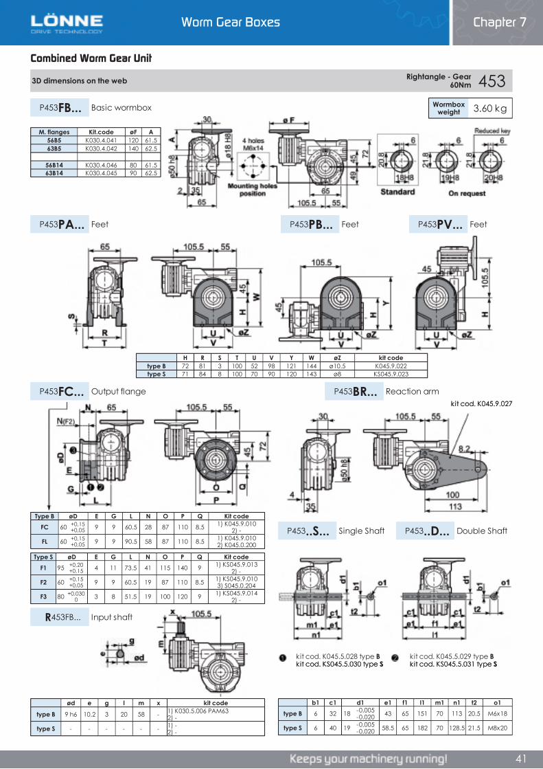
Worm Gear Boxes Chapter 7
40
Combined Worm Gear Unit
453 Rightangle - Gear 045+030 60Nm Rating Alluminium
AGIP KLUBER SHELL MOBILTelium VSF 320 Syntheso D220 EP Tivela Oil WB Glygoyl 30 SHC 630
RADIAL AND AXIAL LOADS
n2[min-1]
FA[N]
FR[N]
1400 20 100
n2[min-1]
FA[N]
FR[N]
25 300 180015 400 2000
• QUICK SELECTION input speed (n 1)=1400 min-1
Outputspeed Ratio Motor
powerOutputtorque
Servicefactor
Nominalpower
Nominaltorque
AvailableB5 motor flanges
AvailableB14 motor flanges
Dynamiceffiency
ToothModule
n2
[min-1] i P1M
[kW]M2M
[Nm] f.s P1R
[kW]M2R
[Nm]A56
B63
O56
P63 RD Mn [mm] Ratios
code10.0 140 0.12 57 1.0 0.13 60 B B- C 50 2.2 017.0 200 0.12 79 0.8 0.09 60 B B- C 48 2.2 025.0 280 0.12* 60 <0.8 0.07 60 B B- C 45 2.4 033.3 420 0.12* 60 <0.8 0.06 60 B B- C 36 1.6 042.5 560 0.12* 60 <0.8 0.05 60 B B- C 33 2.5 051.9 740 0.12* 60 <0.8 0.04 60 B B- C 30 1.8 061.5 920 0.12* 60 <0.8 0.04 60 B B- C 27 1.5 071.3 1120 0.12* 60 <0.8 0.03 60 B B- C 26 2.5 080.9 1480 0.12* 60 <0.8 0.02 60 B B- C 24 1.8 090.8 1840 0.12* 60 <0.8 0.02 60 B B- C 22 1.5 100.6 2400 0.12* 60 <0.8 0.02 60 B B- C 21 1.2 11
Unit 453 is supplied with synthetic oil, providing “long life” lubrication. For mounting position V5- V6 please contact us.
See table 1 for lubrication and recommended quantity.
In table 2 please see possible radial loads and axial loads on the gearbox.
Tab 2
Tab 1
LUBRICATION 453 OIL Quantity 0.09/0.06 Lt
Input Shaft
Output Shaft
*Strong axial loads in the DX direction are not allowed.
* Power higher than the maximum one which can be supported by the gearbox. Select according to the torque M2R
Motor Flanges Available C) Motor Flange Holes PositionB) Available on Request without reduction bushingB) Supplied with Reduction Bushing
Combined Worm Gear Unit
Chapter 7Worm Gear Boxes
Combined Worm Gear Unit
453 Rightangle - Gear 045+030 60Nm Rating Alluminium
AGIP KLUBER SHELL MOBILTelium VSF 320 Syntheso D220 EP Tivela Oil WB Glygoyl 30 SHC 630
RADIAL AND AXIAL LOADS
n2[min-1]
FA[N]
FR[N]
1400 20 100
n2[min-1]
FA[N]
FR[N]
25 300 180015 400 2000
• QUICK SELECTION input speed (n 1)=1400 min-1
Outputspeed Ratio Motor
powerOutputtorque
Servicefactor
Nominalpower
Nominaltorque
AvailableB5 motor flanges
AvailableB14 motor flanges
Dynamiceffiency
ToothModule
n2
[min-1] i P1M
[kW]M2M
[Nm] f.s P1R
[kW]M2R
[Nm]A56
B63
O56
P63 RD Mn [mm] Ratios
code10.0 140 0.12 57 1.0 0.13 60 B B- C 50 2.2 017.0 200 0.12 79 0.8 0.09 60 B B- C 48 2.2 025.0 280 0.12* 60 <0.8 0.07 60 B B- C 45 2.4 033.3 420 0.12* 60 <0.8 0.06 60 B B- C 36 1.6 042.5 560 0.12* 60 <0.8 0.05 60 B B- C 33 2.5 051.9 740 0.12* 60 <0.8 0.04 60 B B- C 30 1.8 061.5 920 0.12* 60 <0.8 0.04 60 B B- C 27 1.5 071.3 1120 0.12* 60 <0.8 0.03 60 B B- C 26 2.5 080.9 1480 0.12* 60 <0.8 0.02 60 B B- C 24 1.8 090.8 1840 0.12* 60 <0.8 0.02 60 B B- C 22 1.5 100.6 2400 0.12* 60 <0.8 0.02 60 B B- C 21 1.2 11
Unit 453 is supplied with synthetic oil, providing “long life” lubrication. For mounting position V5- V6 please contact us.
See table 1 for lubrication and recommended quantity.
In table 2 please see possible radial loads and axial loads on the gearbox.
Tab 2
Tab 1
LUBRICATION 453 OIL Quantity 0.09/0.06 Lt
Input Shaft
Output Shaft
*Strong axial loads in the DX direction are not allowed.
* Power higher than the maximum one which can be supported by the gearbox. Select according to the torque M2R
Motor Flanges Available C) Motor Flange Holes PositionB) Available on Request without reduction bushingB) Supplied with Reduction Bushing
40
453 Rightangle - Gear 045+030 60Nm Rating Alluminium
AGIP KLUBER SHELL MOBILTelium VSF 320 Syntheso D220 EP Tivela Oil WB Glygoyl 30 SHC 630
RADIAL AND AXIAL LOADS
n2[min-1]
FA[N]
FR[N]
1400 20 100
n2[min-1]
FA[N]
FR[N]
25 300 180015 400 2000
• QUICK SELECTION input speed (n 1)=1400 min-1
Outputspeed Ratio Motor
powerOutputtorque
Servicefactor
Nominalpower
Nominaltorque
AvailableB5 motor flanges
AvailableB14 motor flanges
Dynamiceffiency
ToothModule
n2
[min-1] i P1M
[kW]M2M
[Nm] f.s P1R
[kW]M2R
[Nm]A56
B63
O56
P63 RD Mn [mm] Ratios
code10.0 140 0.12 57 1.0 0.13 60 B B- C 50 2.2 017.0 200 0.12 79 0.8 0.09 60 B B- C 48 2.2 025.0 280 0.12* 60 <0.8 0.07 60 B B- C 45 2.4 033.3 420 0.12* 60 <0.8 0.06 60 B B- C 36 1.6 042.5 560 0.12* 60 <0.8 0.05 60 B B- C 33 2.5 051.9 740 0.12* 60 <0.8 0.04 60 B B- C 30 1.8 061.5 920 0.12* 60 <0.8 0.04 60 B B- C 27 1.5 071.3 1120 0.12* 60 <0.8 0.03 60 B B- C 26 2.5 080.9 1480 0.12* 60 <0.8 0.02 60 B B- C 24 1.8 090.8 1840 0.12* 60 <0.8 0.02 60 B B- C 22 1.5 100.6 2400 0.12* 60 <0.8 0.02 60 B B- C 21 1.2 11
Unit 453 is supplied with synthetic oil, providing “long life” lubrication. For mounting position V5- V6 please contact us.
See table 1 for lubrication and recommended quantity.
In table 2 please see possible radial loads and axial loads on the gearbox.
Tab 2
Tab 1
LUBRICATION 453 OIL Quantity 0.09/0.06 Lt
Input Shaft
Output Shaft
*Strong axial loads in the DX direction are not allowed.
* Power higher than the maximum one which can be supported by the gearbox. Select according to the torque M2R
Motor Flanges Available C) Motor Flange Holes PositionB) Available on Request without reduction bushingB) Supplied with Reduction Bushing
Worm Gear Boxes Chapter 7
40
Worm Gear Boxes Chapter 7
41
Combined Worm Gear Unit
3D dimensions on the web Rightangle - Gear 60Nm 453
Wormboxweight 3.60 kgP453FB... Basic wormbox
P453PB... FeetP453PA... Feet P453PV... Feet
P453FC... Output flange P453BR... Reaction arm
P453..S... Single Shaft P453..D... Double Shaft
R453FB... Input shaft
Type B øD E G L N O P Q Kit codeFC 60 +0,15
+0,05 9 9 60.5 28 87 110 8.5 1) K045.9.010 2) -
FL 60 +0,15+0,05 9 9 90.5 58 87 110 8.5 1) K045.9.010
2) K045.0.200
Type S øD E G L N O P Q Kit codeF1 95 +0,20
+0,15 4 11 73.5 41 115 140 9 1) KS045.9.013 2) -
F2 60 +0,15+0,05 9 9 60.5 19 87 110 8.5 1) KS045.9.010
3) S045.0.204
F3 80 +0,0300 3 8 51.5 19 100 120 9 1) KS045.9.014
2) -
b1 c1 d1 e1 f1 l1 m1 n1 t2 o1type B 6 32 18 -0,005
-0,020 43 65 151 70 113 20.5 M6x18
type S 6 40 19 -0,005-0,020 58.5 65 182 70 128.5 21.5 M8x20
M. flanges Kit.code øF A56B5 K030.4.041 120 61.563B5 K030.4.042 140 62.5
56B14 K030.4.046 80 61.563B14 K030.4.045 90 62.5
ød e g l m x kit code
type B 9 h6 10.2 3 20 58 - 1) K030.5.006 PAM63 2) -
type S - - - - - - 1) -2) -
H R S T U V Y W øZ kit codetype B 72 81 3 100 52 98 121 144 ø10.5 K045.9.022type S 71 84 8 100 70 90 120 143 ø8 KS045.9.023
kit cod. K045.5.029 type Bkit cod. KS045.5.031 type S
kit cod. K045.5.028 type Bkit cod. KS045.5.030 type S
kit cod. K045.9.027
Combined Worm Gear Unit
Chapter 7Worm Gear Boxes
Combined Worm Gear Unit
3D dimensions on the web Rightangle - Gear 60Nm 453
Wormboxweight 3.60 kgP453FB... Basic wormbox
P453PB... FeetP453PA... Feet P453PV... Feet
P453FC... Output flange P453BR... Reaction arm
P453..S... Single Shaft P453..D... Double Shaft
R453FB... Input shaft
Type B øD E G L N O P Q Kit codeFC 60 +0,15
+0,05 9 9 60.5 28 87 110 8.5 1) K045.9.010 2) -
FL 60 +0,15+0,05 9 9 90.5 58 87 110 8.5 1) K045.9.010
2) K045.0.200
Type S øD E G L N O P Q Kit codeF1 95 +0,20
+0,15 4 11 73.5 41 115 140 9 1) KS045.9.013 2) -
F2 60 +0,15+0,05 9 9 60.5 19 87 110 8.5 1) KS045.9.010
3) S045.0.204
F3 80 +0,0300 3 8 51.5 19 100 120 9 1) KS045.9.014
2) -
b1 c1 d1 e1 f1 l1 m1 n1 t2 o1type B 6 32 18 -0,005
-0,020 43 65 151 70 113 20.5 M6x18
type S 6 40 19 -0,005-0,020 58.5 65 182 70 128.5 21.5 M8x20
M. flanges Kit.code øF A56B5 K030.4.041 120 61.563B5 K030.4.042 140 62.5
56B14 K030.4.046 80 61.563B14 K030.4.045 90 62.5
ød e g l m x kit code
type B 9 h6 10.2 3 20 58 - 1) K030.5.006 PAM63 2) -
type S - - - - - - 1) -2) -
H R S T U V Y W øZ kit codetype B 72 81 3 100 52 98 121 144 ø10.5 K045.9.022type S 71 84 8 100 70 90 120 143 ø8 KS045.9.023
kit cod. K045.5.029 type Bkit cod. KS045.5.031 type S
kit cod. K045.5.028 type Bkit cod. KS045.5.030 type S
kit cod. K045.9.027
41
Worm Gear Boxes Chapter 7
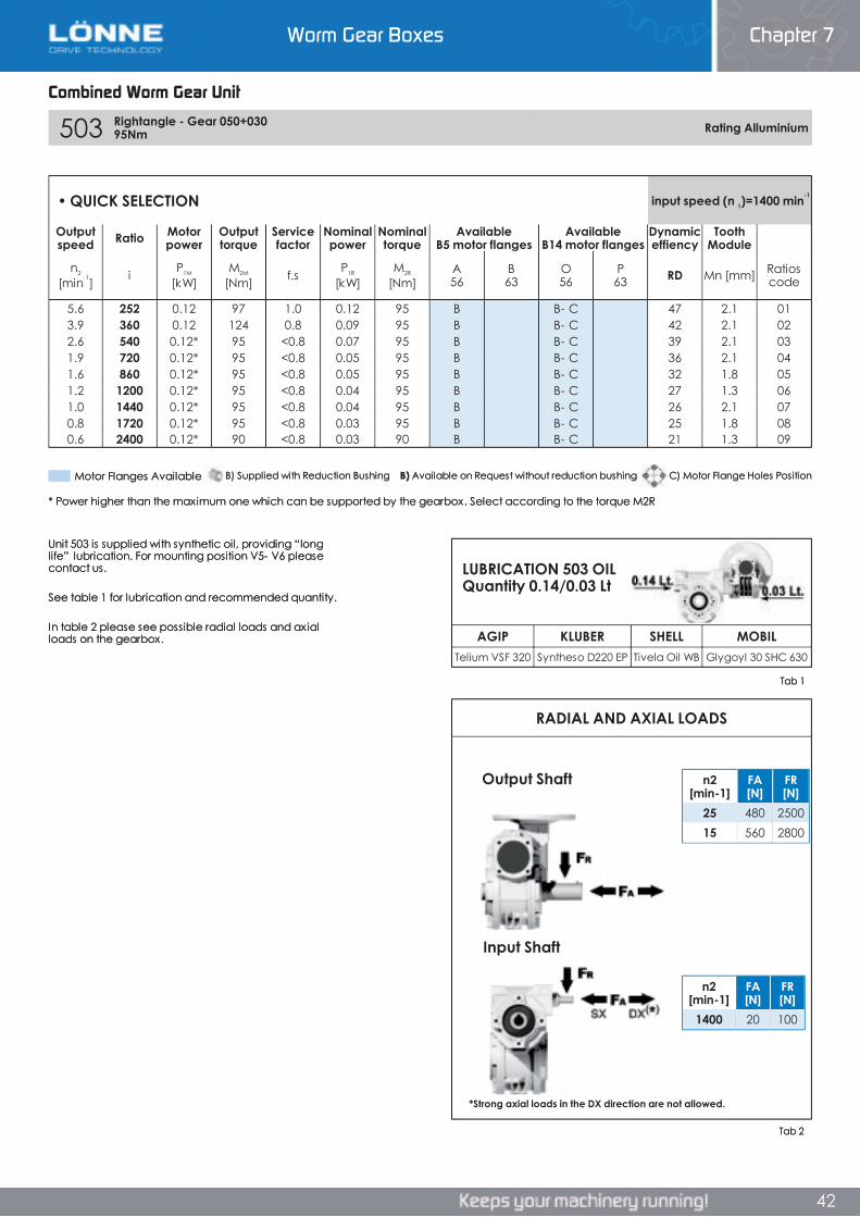
Worm Gear Boxes Chapter 7
42
Combined Worm Gear Unit
503 Rightangle - Gear 050+030 95Nm Rating Alluminium
AGIP KLUBER SHELL MOBILTelium VSF 320 Syntheso D220 EP Tivela Oil WB Glygoyl 30 SHC 630
RADIAL AND AXIAL LOADS
n2[min-1]
FA[N]
FR[N]
1400 20 100
n2[min-1]
FA[N]
FR[N]
25 480 250015 560 2800
• QUICK SELECTION input speed (n 1)=1400 min-1
Outputspeed Ratio Motor
powerOutputtorque
Servicefactor
Nominalpower
Nominaltorque
AvailableB5 motor flanges
AvailableB14 motor flanges
Dynamiceffiency
ToothModule
n2
[min-1] i P1M
[kW]M2M
[Nm] f.s P1R
[kW]M2R
[Nm]A56
B63
O56
P63 RD Mn [mm] Ratios
code
5.6 252 0.12 97 1.0 0.12 95 B B- C 47 2.1 013.9 360 0.12 124 0.8 0.09 95 B B- C 42 2.1 022.6 540 0.12* 95 <0.8 0.07 95 B B- C 39 2.1 031.9 720 0.12* 95 <0.8 0.05 95 B B- C 36 2.1 041.6 860 0.12* 95 <0.8 0.05 95 B B- C 32 1.8 051.2 1200 0.12* 95 <0.8 0.04 95 B B- C 27 1.3 061.0 1440 0.12* 95 <0.8 0.04 95 B B- C 26 2.1 070.8 1720 0.12* 95 <0.8 0.03 95 B B- C 25 1.8 080.6 2400 0.12* 90 <0.8 0.03 90 B B- C 21 1.3 09
Unit 503 is supplied with synthetic oil, providing “long life” lubrication. For mounting position V5- V6 please contact us.
See table 1 for lubrication and recommended quantity.
In table 2 please see possible radial loads and axial loads on the gearbox.
Tab 2
Tab 1
LUBRICATION 503 OIL Quantity 0.14/0.03 Lt
Input Shaft
Output Shaft
*Strong axial loads in the DX direction are not allowed.
* Power higher than the maximum one which can be supported by the gearbox. Select according to the torque M2R
B) Supplied with Reduction Bushing B) Available on Request without reduction bushing C) Motor Flange Holes PositionMotor Flanges Available
Combined Worm Gear Unit
Chapter 7Worm Gear Boxes
Combined Worm Gear Unit
503 Rightangle - Gear 050+030 95Nm Rating Alluminium
AGIP KLUBER SHELL MOBILTelium VSF 320 Syntheso D220 EP Tivela Oil WB Glygoyl 30 SHC 630
RADIAL AND AXIAL LOADS
n2[min-1]
FA[N]
FR[N]
1400 20 100
n2[min-1]
FA[N]
FR[N]
25 480 250015 560 2800
• QUICK SELECTION input speed (n 1)=1400 min-1
Outputspeed Ratio Motor
powerOutputtorque
Servicefactor
Nominalpower
Nominaltorque
AvailableB5 motor flanges
AvailableB14 motor flanges
Dynamiceffiency
ToothModule
n2
[min-1] i P1M
[kW]M2M
[Nm] f.s P1R
[kW]M2R
[Nm]A56
B63
O56
P63 RD Mn [mm] Ratios
code
5.6 252 0.12 97 1.0 0.12 95 B B- C 47 2.1 013.9 360 0.12 124 0.8 0.09 95 B B- C 42 2.1 022.6 540 0.12* 95 <0.8 0.07 95 B B- C 39 2.1 031.9 720 0.12* 95 <0.8 0.05 95 B B- C 36 2.1 041.6 860 0.12* 95 <0.8 0.05 95 B B- C 32 1.8 051.2 1200 0.12* 95 <0.8 0.04 95 B B- C 27 1.3 061.0 1440 0.12* 95 <0.8 0.04 95 B B- C 26 2.1 070.8 1720 0.12* 95 <0.8 0.03 95 B B- C 25 1.8 080.6 2400 0.12* 90 <0.8 0.03 90 B B- C 21 1.3 09
Unit 503 is supplied with synthetic oil, providing “long life” lubrication. For mounting position V5- V6 please contact us.
See table 1 for lubrication and recommended quantity.
In table 2 please see possible radial loads and axial loads on the gearbox.
Tab 2
Tab 1
LUBRICATION 503 OIL Quantity 0.14/0.03 Lt
Input Shaft
Output Shaft
*Strong axial loads in the DX direction are not allowed.
* Power higher than the maximum one which can be supported by the gearbox. Select according to the torque M2R
B) Supplied with Reduction Bushing B) Available on Request without reduction bushing C) Motor Flange Holes PositionMotor Flanges Available
42
503 Rightangle - Gear 050+030 95Nm Rating Alluminium
AGIP KLUBER SHELL MOBILTelium VSF 320 Syntheso D220 EP Tivela Oil WB Glygoyl 30 SHC 630
RADIAL AND AXIAL LOADS
n2[min-1]
FA[N]
FR[N]
1400 20 100
n2[min-1]
FA[N]
FR[N]
25 480 250015 560 2800
• QUICK SELECTION input speed (n 1)=1400 min-1
Outputspeed Ratio Motor
powerOutputtorque
Servicefactor
Nominalpower
Nominaltorque
AvailableB5 motor flanges
AvailableB14 motor flanges
Dynamiceffiency
ToothModule
n2
[min-1] i P1M
[kW]M2M
[Nm] f.s P1R
[kW]M2R
[Nm]A56
B63
O56
P63 RD Mn [mm] Ratios
code
5.6 252 0.12 97 1.0 0.12 95 B B- C 47 2.1 013.9 360 0.12 124 0.8 0.09 95 B B- C 42 2.1 022.6 540 0.12* 95 <0.8 0.07 95 B B- C 39 2.1 031.9 720 0.12* 95 <0.8 0.05 95 B B- C 36 2.1 041.6 860 0.12* 95 <0.8 0.05 95 B B- C 32 1.8 051.2 1200 0.12* 95 <0.8 0.04 95 B B- C 27 1.3 061.0 1440 0.12* 95 <0.8 0.04 95 B B- C 26 2.1 070.8 1720 0.12* 95 <0.8 0.03 95 B B- C 25 1.8 080.6 2400 0.12* 90 <0.8 0.03 90 B B- C 21 1.3 09
Unit 503 is supplied with synthetic oil, providing “long life” lubrication. For mounting position V5- V6 please contact us.
See table 1 for lubrication and recommended quantity.
In table 2 please see possible radial loads and axial loads on the gearbox.
Tab 2
Tab 1
LUBRICATION 503 OIL Quantity 0.14/0.03 Lt
Input Shaft
Output Shaft
*Strong axial loads in the DX direction are not allowed.
* Power higher than the maximum one which can be supported by the gearbox. Select according to the torque M2R
B) Supplied with Reduction Bushing B) Available on Request without reduction bushing C) Motor Flange Holes PositionMotor Flanges Available
Worm Gear Boxes Chapter 7
42
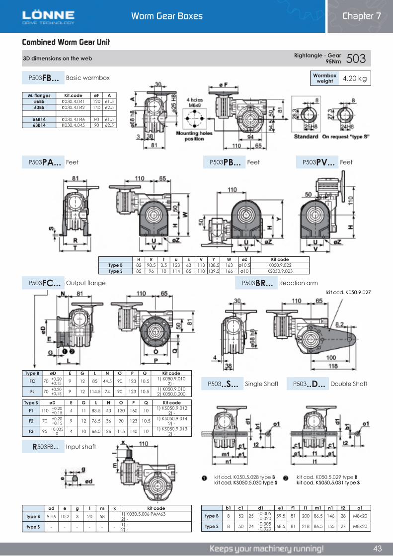
Worm Gear Boxes Chapter 7
43
Combined Worm Gear Unit
3D dimensions on the web Rightangle - Gear 95Nm 503
Wormboxweight 4.20 kgP503FB... Basic wormbox
P503PB... FeetP503PA... Feet P503PV... Feet
P503FC... Output flange P503BR... Reaction arm
P503..S... Single Shaft P503..D... Double Shaft
R503FB... Input shaft
Type B øD E G L N O P Q Kit codeFC 70 +0,20
+0,15 9 12 85 44.5 90 123 10.5 1) K050.9.010 2) -
FL 70 +0,20+0,15 9 12 114.5 74 90 123 10.5 1) K050.9.010
2) K050.0.200
Type S øD E G L N O P Q Kit codeF1 110 +0,20
+0,15 4 11 83.5 43 130 160 10 1) KS050.9.012 2) -
F2 70 +0,20+0,15 9 12 76.5 36 90 123 10.5 1) KS050.9.014
2) -
F3 95 +0,0350 4 10 66.5 26 115 140 10 1) KS050.9.013
2) -
b1 c1 d1 e1 f1 l1 m1 n1 t2 o1type B 8 52 25 -0,005
-0,020 59.5 81 200 86.5 146 28 M8x20
type S 8 50 24 -0,005-0,020 68.5 81 218 86.5 155 27 M8x20
M. flanges Kit.code øF A56B5 K030.4.041 120 61.563B5 K030.4.042 140 62.5
56B14 K030.4.046 80 61.563B14 K030.4.045 90 62.5
H R t u S V Y W øZ Kit codeType B 82 98.5 3.5 123 63 113 138.5 163 ø10.5 K050.9.022Type S 85 96 10 114 85 110 139.5 166 ø10 KS050.9.023
ød e g l m x kit code
type B 9 h6 10.2 3 20 58 - 1) K030.5.006 PAM63 2) -
type S - - - - - - 1) -2) -
kit cod. K050.5.029 type Bkit cod. KS050.5.031 type S
kit cod. K050.5.028 type Bkit cod. KS050.5.030 type S
kit cod. K050.9.027
Combined Worm Gear Unit
Chapter 7Worm Gear Boxes
Combined Worm Gear Unit
3D dimensions on the web Rightangle - Gear 95Nm 503
Wormboxweight 4.20 kgP503FB... Basic wormbox
P503PB... FeetP503PA... Feet P503PV... Feet
P503FC... Output flange P503BR... Reaction arm
P503..S... Single Shaft P503..D... Double Shaft
R503FB... Input shaft
Type B øD E G L N O P Q Kit codeFC 70 +0,20
+0,15 9 12 85 44.5 90 123 10.5 1) K050.9.010 2) -
FL 70 +0,20+0,15 9 12 114.5 74 90 123 10.5 1) K050.9.010
2) K050.0.200
Type S øD E G L N O P Q Kit codeF1 110 +0,20
+0,15 4 11 83.5 43 130 160 10 1) KS050.9.012 2) -
F2 70 +0,20+0,15 9 12 76.5 36 90 123 10.5 1) KS050.9.014
2) -
F3 95 +0,0350 4 10 66.5 26 115 140 10 1) KS050.9.013
2) -
b1 c1 d1 e1 f1 l1 m1 n1 t2 o1type B 8 52 25 -0,005
-0,020 59.5 81 200 86.5 146 28 M8x20
type S 8 50 24 -0,005-0,020 68.5 81 218 86.5 155 27 M8x20
M. flanges Kit.code øF A56B5 K030.4.041 120 61.563B5 K030.4.042 140 62.5
56B14 K030.4.046 80 61.563B14 K030.4.045 90 62.5
H R t u S V Y W øZ Kit codeType B 82 98.5 3.5 123 63 113 138.5 163 ø10.5 K050.9.022Type S 85 96 10 114 85 110 139.5 166 ø10 KS050.9.023
ød e g l m x kit code
type B 9 h6 10.2 3 20 58 - 1) K030.5.006 PAM63 2) -
type S - - - - - - 1) -2) -
kit cod. K050.5.029 type Bkit cod. KS050.5.031 type S
kit cod. K050.5.028 type Bkit cod. KS050.5.030 type S
kit cod. K050.9.027
43
Worm Gear Boxes Chapter 7
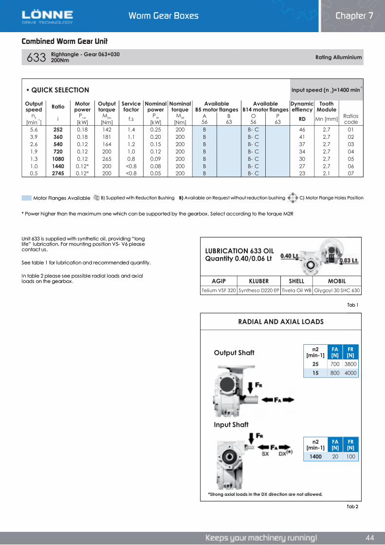
Worm Gear Boxes Chapter 7
44
Combined Worm Gear Unit
633 Rightangle - Gear 063+030 200Nm Rating Alluminium
AGIP KLUBER SHELL MOBILTelium VSF 320 Syntheso D220 EP Tivela Oil WB Glygoyl 30 SHC 630
RADIAL AND AXIAL LOADS
n2[min-1]
FA[N]
FR[N]
1400 20 100
n2[min-1]
FA[N]
FR[N]
25 700 380015 800 4000
• QUICK SELECTION input speed (n 1)=1400 min-1
Outputspeed Ratio Motor
powerOutputtorque
Servicefactor
Nominalpower
Nominaltorque
AvailableB5 motor flanges
AvailableB14 motor flanges
Dynamiceffiency
ToothModule
n2
[min-1] i P1M
[kW]M2M
[Nm] f.s P1R
[kW]M2R
[Nm]A56
B63
O56
P63 RD Mn [mm] Ratios
code5.6 252 0.18 142 1.4 0.25 200 B B- C 46 2.7 013.9 360 0.18 181 1.1 0.20 200 B B- C 41 2.7 022.6 540 0.12 164 1.2 0.15 200 B B- C 37 2.7 031.9 720 0.12 200 1.0 0.12 200 B B- C 34 2.7 041.3 1080 0.12 265 0.8 0.09 200 B B- C 30 2.7 051.0 1440 0.12* 200 <0.8 0.08 200 B B- C 27 2.7 060.5 2745 0.12* 200 <0.8 0.05 200 B B- C 23 2.1 07
Unit 633 is supplied with synthetic oil, providing “long life” lubrication. For mounting position V5- V6 please contact us.
See table 1 for lubrication and recommended quantity.
In table 2 please see possible radial loads and axial loads on the gearbox.
Tab 2
Tab 1
LUBRICATION 633 OIL Quantity 0.40/0.06 Lt
Input Shaft
Output Shaft
*Strong axial loads in the DX direction are not allowed.
* Power higher than the maximum one which can be supported by the gearbox. Select according to the torque M2R
B) Supplied with Reduction Bushing B) Available on Request without reduction bushing C) Motor Flange Holes PositionMotor Flanges Available
Combined Worm Gear Unit
Chapter 7Worm Gear Boxes
Combined Worm Gear Unit
633 Rightangle - Gear 063+030 200Nm Rating Alluminium
AGIP KLUBER SHELL MOBILTelium VSF 320 Syntheso D220 EP Tivela Oil WB Glygoyl 30 SHC 630
RADIAL AND AXIAL LOADS
n2[min-1]
FA[N]
FR[N]
1400 20 100
n2[min-1]
FA[N]
FR[N]
25 700 380015 800 4000
• QUICK SELECTION input speed (n 1)=1400 min-1
Outputspeed Ratio Motor
powerOutputtorque
Servicefactor
Nominalpower
Nominaltorque
AvailableB5 motor flanges
AvailableB14 motor flanges
Dynamiceffiency
ToothModule
n2
[min-1] i P1M
[kW]M2M
[Nm] f.s P1R
[kW]M2R
[Nm]A56
B63
O56
P63 RD Mn [mm] Ratios
code5.6 252 0.18 142 1.4 0.25 200 B B- C 46 2.7 013.9 360 0.18 181 1.1 0.20 200 B B- C 41 2.7 022.6 540 0.12 164 1.2 0.15 200 B B- C 37 2.7 031.9 720 0.12 200 1.0 0.12 200 B B- C 34 2.7 041.3 1080 0.12 265 0.8 0.09 200 B B- C 30 2.7 051.0 1440 0.12* 200 <0.8 0.08 200 B B- C 27 2.7 060.5 2745 0.12* 200 <0.8 0.05 200 B B- C 23 2.1 07
Unit 633 is supplied with synthetic oil, providing “long life” lubrication. For mounting position V5- V6 please contact us.
See table 1 for lubrication and recommended quantity.
In table 2 please see possible radial loads and axial loads on the gearbox.
Tab 2
Tab 1
LUBRICATION 633 OIL Quantity 0.40/0.06 Lt
Input Shaft
Output Shaft
*Strong axial loads in the DX direction are not allowed.
* Power higher than the maximum one which can be supported by the gearbox. Select according to the torque M2R
B) Supplied with Reduction Bushing B) Available on Request without reduction bushing C) Motor Flange Holes PositionMotor Flanges Available
44
633 Rightangle - Gear 063+030 200Nm Rating Alluminium
AGIP KLUBER SHELL MOBILTelium VSF 320 Syntheso D220 EP Tivela Oil WB Glygoyl 30 SHC 630
RADIAL AND AXIAL LOADS
n2[min-1]
FA[N]
FR[N]
1400 20 100
n2[min-1]
FA[N]
FR[N]
25 700 380015 800 4000
• QUICK SELECTION input speed (n 1)=1400 min-1
Outputspeed Ratio Motor
powerOutputtorque
Servicefactor
Nominalpower
Nominaltorque
AvailableB5 motor flanges
AvailableB14 motor flanges
Dynamiceffiency
ToothModule
n2
[min-1] i P1M
[kW]M2M
[Nm] f.s P1R
[kW]M2R
[Nm]A56
B63
O56
P63 RD Mn [mm] Ratios
code5.6 252 0.18 142 1.4 0.25 200 B B- C 46 2.7 013.9 360 0.18 181 1.1 0.20 200 B B- C 41 2.7 022.6 540 0.12 164 1.2 0.15 200 B B- C 37 2.7 031.9 720 0.12 200 1.0 0.12 200 B B- C 34 2.7 041.3 1080 0.12 265 0.8 0.09 200 B B- C 30 2.7 051.0 1440 0.12* 200 <0.8 0.08 200 B B- C 27 2.7 060.5 2745 0.12* 200 <0.8 0.05 200 B B- C 23 2.1 07
Unit 633 is supplied with synthetic oil, providing “long life” lubrication. For mounting position V5- V6 please contact us.
See table 1 for lubrication and recommended quantity.
In table 2 please see possible radial loads and axial loads on the gearbox.
Tab 2
Tab 1
LUBRICATION 633 OIL Quantity 0.40/0.06 Lt
Input Shaft
Output Shaft
*Strong axial loads in the DX direction are not allowed.
* Power higher than the maximum one which can be supported by the gearbox. Select according to the torque M2R
B) Supplied with Reduction Bushing B) Available on Request without reduction bushing C) Motor Flange Holes PositionMotor Flanges Available
Worm Gear Boxes Chapter 7
44
Worm Gear Boxes Chapter 7
44
Combined Worm Gear Unit
633 Rightangle - Gear 063+030 200Nm Rating Alluminium
AGIP KLUBER SHELL MOBILTelium VSF 320 Syntheso D220 EP Tivela Oil WB Glygoyl 30 SHC 630
RADIAL AND AXIAL LOADS
n2[min-1]
FA[N]
FR[N]
1400 20 100
n2[min-1]
FA[N]
FR[N]
25 700 380015 800 4000
• QUICK SELECTION input speed (n 1)=1400 min-1
Outputspeed Ratio Motor
powerOutputtorque
Servicefactor
Nominalpower
Nominaltorque
AvailableB5 motor flanges
AvailableB14 motor flanges
Dynamiceffiency
ToothModule
n2
[min-1] i P1M
[kW]M2M
[Nm] f.s P1R
[kW]M2R
[Nm]A56
B63
O56
P63 RD Mn [mm] Ratios
code5.6 252 0.18 142 1.4 0.25 200 B B- C 46 2.7 013.9 360 0.18 181 1.1 0.20 200 B B- C 41 2.7 022.6 540 0.12 164 1.2 0.15 200 B B- C 37 2.7 031.9 720 0.12 200 1.0 0.12 200 B B- C 34 2.7 041.3 1080 0.12 265 0.8 0.09 200 B B- C 30 2.7 051.0 1440 0.12* 200 <0.8 0.08 200 B B- C 27 2.7 060.5 2745 0.12* 200 <0.8 0.05 200 B B- C 23 2.1 07
Unit 633 is supplied with synthetic oil, providing “long life” lubrication. For mounting position V5- V6 please contact us.
See table 1 for lubrication and recommended quantity.
In table 2 please see possible radial loads and axial loads on the gearbox.
Tab 2
Tab 1
LUBRICATION 633 OIL Quantity 0.40/0.06 Lt
Input Shaft
Output Shaft
*Strong axial loads in the DX direction are not allowed.
* Power higher than the maximum one which can be supported by the gearbox. Select according to the torque M2R
B) Supplied with Reduction Bushing B) Available on Request without reduction bushing C) Motor Flange Holes PositionMotor Flanges Available
Combined Worm Gear Unit
Chapter 7Worm Gear Boxes
Combined Worm Gear Unit
633 Rightangle - Gear 063+030 200Nm Rating Alluminium
AGIP KLUBER SHELL MOBILTelium VSF 320 Syntheso D220 EP Tivela Oil WB Glygoyl 30 SHC 630
RADIAL AND AXIAL LOADS
n2[min-1]
FA[N]
FR[N]
1400 20 100
n2[min-1]
FA[N]
FR[N]
25 700 380015 800 4000
• QUICK SELECTION input speed (n 1)=1400 min-1
Outputspeed Ratio Motor
powerOutputtorque
Servicefactor
Nominalpower
Nominaltorque
AvailableB5 motor flanges
AvailableB14 motor flanges
Dynamiceffiency
ToothModule
n2
[min-1] i P1M
[kW]M2M
[Nm] f.s P1R
[kW]M2R
[Nm]A56
B63
O56
P63 RD Mn [mm] Ratios
code5.6 252 0.18 142 1.4 0.25 200 B B- C 46 2.7 013.9 360 0.18 181 1.1 0.20 200 B B- C 41 2.7 022.6 540 0.12 164 1.2 0.15 200 B B- C 37 2.7 031.9 720 0.12 200 1.0 0.12 200 B B- C 34 2.7 041.3 1080 0.12 265 0.8 0.09 200 B B- C 30 2.7 051.0 1440 0.12* 200 <0.8 0.08 200 B B- C 27 2.7 060.5 2745 0.12* 200 <0.8 0.05 200 B B- C 23 2.1 07
Unit 633 is supplied with synthetic oil, providing “long life” lubrication. For mounting position V5- V6 please contact us.
See table 1 for lubrication and recommended quantity.
In table 2 please see possible radial loads and axial loads on the gearbox.
Tab 2
Tab 1
LUBRICATION 633 OIL Quantity 0.40/0.06 Lt
Input Shaft
Output Shaft
*Strong axial loads in the DX direction are not allowed.
* Power higher than the maximum one which can be supported by the gearbox. Select according to the torque M2R
B) Supplied with Reduction Bushing B) Available on Request without reduction bushing C) Motor Flange Holes PositionMotor Flanges Available
44
633 Rightangle - Gear 063+030 200Nm Rating Alluminium
AGIP KLUBER SHELL MOBILTelium VSF 320 Syntheso D220 EP Tivela Oil WB Glygoyl 30 SHC 630
RADIAL AND AXIAL LOADS
n2[min-1]
FA[N]
FR[N]
1400 20 100
n2[min-1]
FA[N]
FR[N]
25 700 380015 800 4000
• QUICK SELECTION input speed (n 1)=1400 min-1
Outputspeed Ratio Motor
powerOutputtorque
Servicefactor
Nominalpower
Nominaltorque
AvailableB5 motor flanges
AvailableB14 motor flanges
Dynamiceffiency
ToothModule
n2
[min-1] i P1M
[kW]M2M
[Nm] f.s P1R
[kW]M2R
[Nm]A56
B63
O56
P63 RD Mn [mm] Ratios
code5.6 252 0.18 142 1.4 0.25 200 B B- C 46 2.7 013.9 360 0.18 181 1.1 0.20 200 B B- C 41 2.7 022.6 540 0.12 164 1.2 0.15 200 B B- C 37 2.7 031.9 720 0.12 200 1.0 0.12 200 B B- C 34 2.7 041.3 1080 0.12 265 0.8 0.09 200 B B- C 30 2.7 051.0 1440 0.12* 200 <0.8 0.08 200 B B- C 27 2.7 060.5 2745 0.12* 200 <0.8 0.05 200 B B- C 23 2.1 07
Unit 633 is supplied with synthetic oil, providing “long life” lubrication. For mounting position V5- V6 please contact us.
See table 1 for lubrication and recommended quantity.
In table 2 please see possible radial loads and axial loads on the gearbox.
Tab 2
Tab 1
LUBRICATION 633 OIL Quantity 0.40/0.06 Lt
Input Shaft
Output Shaft
*Strong axial loads in the DX direction are not allowed.
* Power higher than the maximum one which can be supported by the gearbox. Select according to the torque M2R
B) Supplied with Reduction Bushing B) Available on Request without reduction bushing C) Motor Flange Holes PositionMotor Flanges Available
Worm Gear Boxes Chapter 7
44

Worm Gear Boxes Chapter 7
44
Combined Worm Gear Unit
633 Rightangle - Gear 063+030 200Nm Rating Alluminium
AGIP KLUBER SHELL MOBILTelium VSF 320 Syntheso D220 EP Tivela Oil WB Glygoyl 30 SHC 630
RADIAL AND AXIAL LOADS
n2[min-1]
FA[N]
FR[N]
1400 20 100
n2[min-1]
FA[N]
FR[N]
25 700 380015 800 4000
• QUICK SELECTION input speed (n 1)=1400 min-1
Outputspeed Ratio Motor
powerOutputtorque
Servicefactor
Nominalpower
Nominaltorque
AvailableB5 motor flanges
AvailableB14 motor flanges
Dynamiceffiency
ToothModule
n2
[min-1] i P1M
[kW]M2M
[Nm] f.s P1R
[kW]M2R
[Nm]A56
B63
O56
P63 RD Mn [mm] Ratios
code5.6 252 0.18 142 1.4 0.25 200 B B- C 46 2.7 013.9 360 0.18 181 1.1 0.20 200 B B- C 41 2.7 022.6 540 0.12 164 1.2 0.15 200 B B- C 37 2.7 031.9 720 0.12 200 1.0 0.12 200 B B- C 34 2.7 041.3 1080 0.12 265 0.8 0.09 200 B B- C 30 2.7 051.0 1440 0.12* 200 <0.8 0.08 200 B B- C 27 2.7 060.5 2745 0.12* 200 <0.8 0.05 200 B B- C 23 2.1 07
Unit 633 is supplied with synthetic oil, providing “long life” lubrication. For mounting position V5- V6 please contact us.
See table 1 for lubrication and recommended quantity.
In table 2 please see possible radial loads and axial loads on the gearbox.
Tab 2
Tab 1
LUBRICATION 633 OIL Quantity 0.40/0.06 Lt
Input Shaft
Output Shaft
*Strong axial loads in the DX direction are not allowed.
* Power higher than the maximum one which can be supported by the gearbox. Select according to the torque M2R
B) Supplied with Reduction Bushing B) Available on Request without reduction bushing C) Motor Flange Holes PositionMotor Flanges Available
Combined Worm Gear Unit
Chapter 7Worm Gear Boxes
Combined Worm Gear Unit
633 Rightangle - Gear 063+030 200Nm Rating Alluminium
AGIP KLUBER SHELL MOBILTelium VSF 320 Syntheso D220 EP Tivela Oil WB Glygoyl 30 SHC 630
RADIAL AND AXIAL LOADS
n2[min-1]
FA[N]
FR[N]
1400 20 100
n2[min-1]
FA[N]
FR[N]
25 700 380015 800 4000
• QUICK SELECTION input speed (n 1)=1400 min-1
Outputspeed Ratio Motor
powerOutputtorque
Servicefactor
Nominalpower
Nominaltorque
AvailableB5 motor flanges
AvailableB14 motor flanges
Dynamiceffiency
ToothModule
n2
[min-1] i P1M
[kW]M2M
[Nm] f.s P1R
[kW]M2R
[Nm]A56
B63
O56
P63 RD Mn [mm] Ratios
code5.6 252 0.18 142 1.4 0.25 200 B B- C 46 2.7 013.9 360 0.18 181 1.1 0.20 200 B B- C 41 2.7 022.6 540 0.12 164 1.2 0.15 200 B B- C 37 2.7 031.9 720 0.12 200 1.0 0.12 200 B B- C 34 2.7 041.3 1080 0.12 265 0.8 0.09 200 B B- C 30 2.7 051.0 1440 0.12* 200 <0.8 0.08 200 B B- C 27 2.7 060.5 2745 0.12* 200 <0.8 0.05 200 B B- C 23 2.1 07
Unit 633 is supplied with synthetic oil, providing “long life” lubrication. For mounting position V5- V6 please contact us.
See table 1 for lubrication and recommended quantity.
In table 2 please see possible radial loads and axial loads on the gearbox.
Tab 2
Tab 1
LUBRICATION 633 OIL Quantity 0.40/0.06 Lt
Input Shaft
Output Shaft
*Strong axial loads in the DX direction are not allowed.
* Power higher than the maximum one which can be supported by the gearbox. Select according to the torque M2R
B) Supplied with Reduction Bushing B) Available on Request without reduction bushing C) Motor Flange Holes PositionMotor Flanges Available
44
633 Rightangle - Gear 063+030 200Nm Rating Alluminium
AGIP KLUBER SHELL MOBILTelium VSF 320 Syntheso D220 EP Tivela Oil WB Glygoyl 30 SHC 630
RADIAL AND AXIAL LOADS
n2[min-1]
FA[N]
FR[N]
1400 20 100
n2[min-1]
FA[N]
FR[N]
25 700 380015 800 4000
• QUICK SELECTION input speed (n 1)=1400 min-1
Outputspeed Ratio Motor
powerOutputtorque
Servicefactor
Nominalpower
Nominaltorque
AvailableB5 motor flanges
AvailableB14 motor flanges
Dynamiceffiency
ToothModule
n2
[min-1] i P1M
[kW]M2M
[Nm] f.s P1R
[kW]M2R
[Nm]A56
B63
O56
P63 RD Mn [mm] Ratios
code5.6 252 0.18 142 1.4 0.25 200 B B- C 46 2.7 013.9 360 0.18 181 1.1 0.20 200 B B- C 41 2.7 022.6 540 0.12 164 1.2 0.15 200 B B- C 37 2.7 031.9 720 0.12 200 1.0 0.12 200 B B- C 34 2.7 041.3 1080 0.12 265 0.8 0.09 200 B B- C 30 2.7 051.0 1440 0.12* 200 <0.8 0.08 200 B B- C 27 2.7 060.5 2745 0.12* 200 <0.8 0.05 200 B B- C 23 2.1 07
Unit 633 is supplied with synthetic oil, providing “long life” lubrication. For mounting position V5- V6 please contact us.
See table 1 for lubrication and recommended quantity.
In table 2 please see possible radial loads and axial loads on the gearbox.
Tab 2
Tab 1
LUBRICATION 633 OIL Quantity 0.40/0.06 Lt
Input Shaft
Output Shaft
*Strong axial loads in the DX direction are not allowed.
* Power higher than the maximum one which can be supported by the gearbox. Select according to the torque M2R
B) Supplied with Reduction Bushing B) Available on Request without reduction bushing C) Motor Flange Holes PositionMotor Flanges Available
Worm Gear Boxes Chapter 7
44
Worm Gear Boxes Chapter 7
45
Combined Worm Gear Unit
3D dimensions on the web Rightangle - Gear 200Nm 633
Wormboxweight 7.50 kgP633FB... Basic wormbox
P633PB... FeetP633PA... Feet P633PV... Feet
P633FC... Output flange P633BR... Reaction arm
P633..S... Single Shaft P633..D... Double Shaft
R633FB... Input shaft
Type B øD E G L N O P Q Kit codeFC 115 +0,20
+0,15 7 13 86 26 150 175 11 1) K063.9.010 2) -
FL 115 +0,20+0,15 7 13 116 56 150 175 11 1) K063.9.010
2) K063.0.200
Type S øD E G L N O P Q Kit codeF1 130 +0,20
+0,15 7 13 102 42 165 200 13 1) KS070.9.013 2) -
F2 115 +0,20+0,15 7 13 116 56 150 175 11 1) KS063.9.013
2) -
F3 110 +0,0350 5 11 82 22 130 160 10 1) KS063.9.011
2) -
b1 c1 d1 e1 f1 l1 m1 n1 t2 o1type B 8 60 25 -0,005
-0,020 63.2 120 246.4 126.8 190 28 M8x20
type S - - - - - - - - - -
ød e g l m x kit code
type B 9 h6 10.2 3 20 58 - 1) K030.5.006 PAM63 2) -
type S - - - - - - 1) -2) -
M. flanges Kit.code øF A56B5 K030.4.041 120 61.563B5 K030.4.042 140 62.5
56B14 K030.4.046 80 61.563B14 K030.4.045 90 62.5
H R t u S V Y W øZ Kit codeType B 100 111 4 144 95 133 170 200 ø10.5 K063.9.022Type S - - - - - - - - - -
kit cod. K063.5.029 type Bkit cod. K063.5.028 type B
kit cod. K063.9.027
Combined Worm Gear Unit
Chapter 7Worm Gear Boxes
Combined Worm Gear Unit
3D dimensions on the web Rightangle - Gear 200Nm 633
Wormboxweight 7.50 kgP633FB... Basic wormbox
P633PB... FeetP633PA... Feet P633PV... Feet
P633FC... Output flange P633BR... Reaction arm
P633..S... Single Shaft P633..D... Double Shaft
R633FB... Input shaft
Type B øD E G L N O P Q Kit codeFC 115 +0,20
+0,15 7 13 86 26 150 175 11 1) K063.9.010 2) -
FL 115 +0,20+0,15 7 13 116 56 150 175 11 1) K063.9.010
2) K063.0.200
Type S øD E G L N O P Q Kit codeF1 130 +0,20
+0,15 7 13 102 42 165 200 13 1) KS070.9.013 2) -
F2 115 +0,20+0,15 7 13 116 56 150 175 11 1) KS063.9.013
2) -
F3 110 +0,0350 5 11 82 22 130 160 10 1) KS063.9.011
2) -
b1 c1 d1 e1 f1 l1 m1 n1 t2 o1type B 8 60 25 -0,005
-0,020 63.2 120 246.4 126.8 190 28 M8x20
type S - - - - - - - - - -
ød e g l m x kit code
type B 9 h6 10.2 3 20 58 - 1) K030.5.006 PAM63 2) -
type S - - - - - - 1) -2) -
M. flanges Kit.code øF A56B5 K030.4.041 120 61.563B5 K030.4.042 140 62.5
56B14 K030.4.046 80 61.563B14 K030.4.045 90 62.5
H R t u S V Y W øZ Kit codeType B 100 111 4 144 95 133 170 200 ø10.5 K063.9.022Type S - - - - - - - - - -
kit cod. K063.5.029 type Bkit cod. K063.5.028 type B
kit cod. K063.9.027
45
Worm Gear Boxes Chapter 7
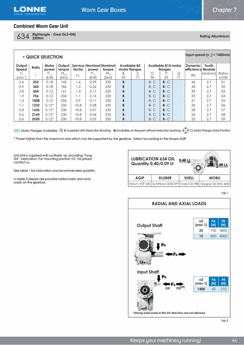
Worm Gear Boxes Chapter 7
46
Combined Worm Gear Unit
634 Rightangle - Gear 063+045 230Nm Rating Alluminium
AGIP KLUBER SHELL MOBILTelium VSF 320 Syntheso D220 EP Tivela Oil WB Glygoyl 30 SHC 630
RADIAL AND AXIAL LOADS
n2[min-1]
FA[N]
FR[N]
1400 42 210
n2[min-1]
FA[N]
FR[N]
25 700 380015 800 4000
• QUICK SELECTION Input speed (n 1) = 1400 min -1
Output Speed Ratio Motor
powerOutput torque
Service factor
Nominal power
Nominal torque
Available B5 motor flanges
Available B14 motor flanges
Dynamic efficiency
Tooth Module
n2
[min-1] i P1M
[kW]M2M
[Nm] f.s. P1R
[kW]M2R
[Nm]B63
C71
O56
P63
Q71 RD Mn [mm] Ratios
code5.6 252 0.18 142 1.6 0.29 230 B B- C B- C 46 2.7 013.9 360 0.18 186 1.2 0.22 230 B B- C B- C 42 2.7 022.8 504 0.12 161 1.4 0.17 230 B B- C B- C 39 2.7 031.9 756 0.12 204 1.1 0.14 230 B B- C B- C 33 2.7 041.4 1008 0.12 256 0.9 0.11 230 B B- C B- C 31 2.7 051.1 1332 0.12* 230 <0.8 0.08 230 B B- C B- C 30 2.7 060.8 1656 0.12* 230 <0.8 0.07 230 B B- C B- C 28 2.7 070.6 2160 0.12* 230 <0.8 0.06 230 B B- C B- C 26 2.7 080.6 2520 0.12* 230 <0.8 0.05 230 B B- C B- C 25 2.7 09
* Power higher than the maximum one which can be supported by the gearbox. Select according to the torque M2R
Unit 634 is supplied with synthetic oil, providing “long life” lubrication. For mounting position V5- V6 please contact us.
See table 1 for lubrication and recommended quantity.
In table 2 please see possible radial loads and axial loads on the gearbox.
Tab 2
Tab 1
LUBRICATION 634 OIL Quantity 0.40/0.09 Lt
Input Shaft
Output Shaft
*Strong axial loads in the DX direction are not allowed.
Motor Flanges Available C) Motor Flange Holes PositionB) Available on Request without reduction bushingB) Supplied with Reduction Bushing
Combined Worm Gear Unit
Chapter 7Worm Gear Boxes
Combined Worm Gear Unit
634 Rightangle - Gear 063+045 230Nm Rating Alluminium
AGIP KLUBER SHELL MOBILTelium VSF 320 Syntheso D220 EP Tivela Oil WB Glygoyl 30 SHC 630
RADIAL AND AXIAL LOADS
n2[min-1]
FA[N]
FR[N]
1400 42 210
n2[min-1]
FA[N]
FR[N]
25 700 380015 800 4000
• QUICK SELECTION Input speed (n 1) = 1400 min -1
Output Speed Ratio Motor
powerOutput torque
Service factor
Nominal power
Nominal torque
Available B5 motor flanges
Available B14 motor flanges
Dynamic efficiency
Tooth Module
n2
[min-1] i P1M
[kW]M2M
[Nm] f.s. P1R
[kW]M2R
[Nm]B63
C71
O56
P63
Q71 RD Mn [mm] Ratios
code5.6 252 0.18 142 1.6 0.29 230 B B- C B- C 46 2.7 013.9 360 0.18 186 1.2 0.22 230 B B- C B- C 42 2.7 022.8 504 0.12 161 1.4 0.17 230 B B- C B- C 39 2.7 031.9 756 0.12 204 1.1 0.14 230 B B- C B- C 33 2.7 041.4 1008 0.12 256 0.9 0.11 230 B B- C B- C 31 2.7 051.1 1332 0.12* 230 <0.8 0.08 230 B B- C B- C 30 2.7 060.8 1656 0.12* 230 <0.8 0.07 230 B B- C B- C 28 2.7 070.6 2160 0.12* 230 <0.8 0.06 230 B B- C B- C 26 2.7 080.6 2520 0.12* 230 <0.8 0.05 230 B B- C B- C 25 2.7 09
* Power higher than the maximum one which can be supported by the gearbox. Select according to the torque M2R
Unit 634 is supplied with synthetic oil, providing “long life” lubrication. For mounting position V5- V6 please contact us.
See table 1 for lubrication and recommended quantity.
In table 2 please see possible radial loads and axial loads on the gearbox.
Tab 2
Tab 1
LUBRICATION 634 OIL Quantity 0.40/0.09 Lt
Input Shaft
Output Shaft
*Strong axial loads in the DX direction are not allowed.
Motor Flanges Available C) Motor Flange Holes PositionB) Available on Request without reduction bushingB) Supplied with Reduction Bushing
46
634 Rightangle - Gear 063+045 230Nm Rating Alluminium
AGIP KLUBER SHELL MOBILTelium VSF 320 Syntheso D220 EP Tivela Oil WB Glygoyl 30 SHC 630
RADIAL AND AXIAL LOADS
n2[min-1]
FA[N]
FR[N]
1400 42 210
n2[min-1]
FA[N]
FR[N]
25 700 380015 800 4000
• QUICK SELECTION Input speed (n 1) = 1400 min -1
Output Speed Ratio Motor
powerOutput torque
Service factor
Nominal power
Nominal torque
Available B5 motor flanges
Available B14 motor flanges
Dynamic efficiency
Tooth Module
n2
[min-1] i P1M
[kW]M2M
[Nm] f.s. P1R
[kW]M2R
[Nm]B63
C71
O56
P63
Q71 RD Mn [mm] Ratios
code5.6 252 0.18 142 1.6 0.29 230 B B- C B- C 46 2.7 013.9 360 0.18 186 1.2 0.22 230 B B- C B- C 42 2.7 022.8 504 0.12 161 1.4 0.17 230 B B- C B- C 39 2.7 031.9 756 0.12 204 1.1 0.14 230 B B- C B- C 33 2.7 041.4 1008 0.12 256 0.9 0.11 230 B B- C B- C 31 2.7 051.1 1332 0.12* 230 <0.8 0.08 230 B B- C B- C 30 2.7 060.8 1656 0.12* 230 <0.8 0.07 230 B B- C B- C 28 2.7 070.6 2160 0.12* 230 <0.8 0.06 230 B B- C B- C 26 2.7 080.6 2520 0.12* 230 <0.8 0.05 230 B B- C B- C 25 2.7 09
* Power higher than the maximum one which can be supported by the gearbox. Select according to the torque M2R
Unit 634 is supplied with synthetic oil, providing “long life” lubrication. For mounting position V5- V6 please contact us.
See table 1 for lubrication and recommended quantity.
In table 2 please see possible radial loads and axial loads on the gearbox.
Tab 2
Tab 1
LUBRICATION 634 OIL Quantity 0.40/0.09 Lt
Input Shaft
Output Shaft
*Strong axial loads in the DX direction are not allowed.
Motor Flanges Available C) Motor Flange Holes PositionB) Available on Request without reduction bushingB) Supplied with Reduction Bushing
Worm Gear Boxes Chapter 7
46
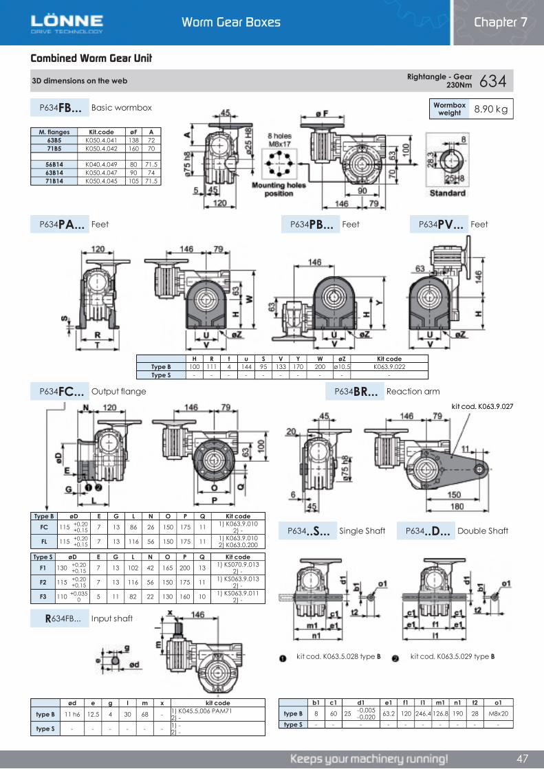
Worm Gear Boxes Chapter 7
47
Combined Worm Gear Unit
3D dimensions on the web Rightangle - Gear 230Nm 634
Wormboxweight 8.90 kgP634FB... Basic wormbox
P634PB... FeetP634PA... Feet P634PV... Feet
P634FC... Output flange P634BR... Reaction arm
P634..S... Single Shaft P634..D... Double Shaft
R634FB... Input shaft
Type B øD E G L N O P Q Kit codeFC 115 +0,20
+0,15 7 13 86 26 150 175 11 1) K063.9.010 2) -
FL 115 +0,20+0,15 7 13 116 56 150 175 11 1) K063.9.010
2) K063.0.200
Type S øD E G L N O P Q Kit codeF1 130 +0,20
+0,15 7 13 102 42 165 200 13 1) KS070.9.013 2) -
F2 115 +0,20+0,15 7 13 116 56 150 175 11 1) KS063.9.013
2) -
F3 110 +0,0350 5 11 82 22 130 160 10 1) KS063.9.011
2) -
b1 c1 d1 e1 f1 l1 m1 n1 t2 o1type B 8 60 25 -0,005
-0,020 63.2 120 246.4 126.8 190 28 M8x20
type S - - - - - - - - - -
H R t u S V Y W øZ Kit codeType B 100 111 4 144 95 133 170 200 ø10.5 K063.9.022Type S - - - - - - - - - -
M. flanges Kit.code øF A63B5 K050.4.041 138 7271B5 K050.4.042 160 70
56B14 K040.4.049 80 71.563B14 K050.4.047 90 7471B14 K050.4.045 105 71.5
ød e g l m x kit code
type B 11 h6 12.5 4 30 68 - 1) K045.5.006 PAM71 2) -
type S - - - - - - 1) -2) -
kit cod. K063.5.029 type Bkit cod. K063.5.028 type B
kit cod. K063.9.027
Combined Worm Gear Unit
Chapter 7Worm Gear Boxes
Combined Worm Gear Unit
3D dimensions on the web Rightangle - Gear 230Nm 634
Wormboxweight 8.90 kgP634FB... Basic wormbox
P634PB... FeetP634PA... Feet P634PV... Feet
P634FC... Output flange P634BR... Reaction arm
P634..S... Single Shaft P634..D... Double Shaft
R634FB... Input shaft
Type B øD E G L N O P Q Kit codeFC 115 +0,20
+0,15 7 13 86 26 150 175 11 1) K063.9.010 2) -
FL 115 +0,20+0,15 7 13 116 56 150 175 11 1) K063.9.010
2) K063.0.200
Type S øD E G L N O P Q Kit codeF1 130 +0,20
+0,15 7 13 102 42 165 200 13 1) KS070.9.013 2) -
F2 115 +0,20+0,15 7 13 116 56 150 175 11 1) KS063.9.013
2) -
F3 110 +0,0350 5 11 82 22 130 160 10 1) KS063.9.011
2) -
b1 c1 d1 e1 f1 l1 m1 n1 t2 o1type B 8 60 25 -0,005
-0,020 63.2 120 246.4 126.8 190 28 M8x20
type S - - - - - - - - - -
H R t u S V Y W øZ Kit codeType B 100 111 4 144 95 133 170 200 ø10.5 K063.9.022Type S - - - - - - - - - -
M. flanges Kit.code øF A63B5 K050.4.041 138 7271B5 K050.4.042 160 70
56B14 K040.4.049 80 71.563B14 K050.4.047 90 7471B14 K050.4.045 105 71.5
ød e g l m x kit code
type B 11 h6 12.5 4 30 68 - 1) K045.5.006 PAM71 2) -
type S - - - - - - 1) -2) -
kit cod. K063.5.029 type Bkit cod. K063.5.028 type B
kit cod. K063.9.027
47
Worm Gear Boxes Chapter 7

Worm Gear Boxes Chapter 7
48
Combined Worm Gear Unit
6A3 Rightangle - Gear 63A +030 252Nm Rating Alluminium
AGIP KLUBER SHELL MOBILTelium VSF 320 Syntheso D220 EP Tivela Oil WB Glygoyl 30 SHC 630
RADIAL AND AXIAL LOADS
n2[min-1]
FA[N]
FR[N]
1400 20 100
n2[min-1]
FA[N]
FR[N]
25 700 380015 800 4000
• QUICK SELECTION input speed (n 1)=1400 min-1
Outputspeed Ratio Motor
powerOutputtorque
Servicefactor
Nominalpower
Nominaltorque
AvailableB5 motor flanges
AvailableB14 motor flanges
Dynamiceffiency
ToothModule
n2
[min-1] i P1M
[kW]M2M
[Nm] f.s P1R
[kW]M2R
[Nm]A56
B63
O56
P63 RD Mn [mm] Ratios
code5.6 252 0.18 142 1.8 0.32 252 B B- C 46 2.7 013.9 360 0.18 181 1.4 0.25 252 B B- C 41 2.7 022.6 540 0.12 164 1.5 0.18 252 B B- C 37 2.7 031.9 720 0.12 200 1.3 0.15 252 B B- C 34 2.7 041.3 1080 0.12 265 1.0 0.11 252 B B- C 30 2.7 051.0 1440 0.12 318 0.8 0.10 252 B B- C 27 2.7 060.5 2745 0.12* 210 <0.8 0.05 210 B B- C 23 2.1 07
* Power higher than the maximum one which can be supported by the gearbox. Select according to the torque M2R
Unit 6A3 is supplied with synthetic oil, providing “long life” lubrication. For mounting position V5- V6 please contact us.
See table 1 for lubrication and recommended quantity.
In table 2 please see possible radial loads and axial loads on the gearbox.
Tab 2
Tab 1
LUBRICATION 6A3 OIL Quantity 0.40/0.06 Lt
Input Shaft
Output Shaft
*Strong axial loads in the DX direction are not allowed.
B) Supplied with Reduction Bushing B) Available on Request without reduction bushing C) Motor Flange Holes PositionMotor Flanges Available
Combined Worm Gear Unit
Chapter 7Worm Gear Boxes
Combined Worm Gear Unit
6A3 Rightangle - Gear 63A +030 252Nm Rating Alluminium
AGIP KLUBER SHELL MOBILTelium VSF 320 Syntheso D220 EP Tivela Oil WB Glygoyl 30 SHC 630
RADIAL AND AXIAL LOADS
n2[min-1]
FA[N]
FR[N]
1400 20 100
n2[min-1]
FA[N]
FR[N]
25 700 380015 800 4000
• QUICK SELECTION input speed (n 1)=1400 min-1
Outputspeed Ratio Motor
powerOutputtorque
Servicefactor
Nominalpower
Nominaltorque
AvailableB5 motor flanges
AvailableB14 motor flanges
Dynamiceffiency
ToothModule
n2
[min-1] i P1M
[kW]M2M
[Nm] f.s P1R
[kW]M2R
[Nm]A56
B63
O56
P63 RD Mn [mm] Ratios
code5.6 252 0.18 142 1.8 0.32 252 B B- C 46 2.7 013.9 360 0.18 181 1.4 0.25 252 B B- C 41 2.7 022.6 540 0.12 164 1.5 0.18 252 B B- C 37 2.7 031.9 720 0.12 200 1.3 0.15 252 B B- C 34 2.7 041.3 1080 0.12 265 1.0 0.11 252 B B- C 30 2.7 051.0 1440 0.12 318 0.8 0.10 252 B B- C 27 2.7 060.5 2745 0.12* 210 <0.8 0.05 210 B B- C 23 2.1 07
* Power higher than the maximum one which can be supported by the gearbox. Select according to the torque M2R
Unit 6A3 is supplied with synthetic oil, providing “long life” lubrication. For mounting position V5- V6 please contact us.
See table 1 for lubrication and recommended quantity.
In table 2 please see possible radial loads and axial loads on the gearbox.
Tab 2
Tab 1
LUBRICATION 6A3 OIL Quantity 0.40/0.06 Lt
Input Shaft
Output Shaft
*Strong axial loads in the DX direction are not allowed.
B) Supplied with Reduction Bushing B) Available on Request without reduction bushing C) Motor Flange Holes PositionMotor Flanges Available
48
6A3 Rightangle - Gear 63A +030 252Nm Rating Alluminium
AGIP KLUBER SHELL MOBILTelium VSF 320 Syntheso D220 EP Tivela Oil WB Glygoyl 30 SHC 630
RADIAL AND AXIAL LOADS
n2[min-1]
FA[N]
FR[N]
1400 20 100
n2[min-1]
FA[N]
FR[N]
25 700 380015 800 4000
• QUICK SELECTION input speed (n 1)=1400 min-1
Outputspeed Ratio Motor
powerOutputtorque
Servicefactor
Nominalpower
Nominaltorque
AvailableB5 motor flanges
AvailableB14 motor flanges
Dynamiceffiency
ToothModule
n2
[min-1] i P1M
[kW]M2M
[Nm] f.s P1R
[kW]M2R
[Nm]A56
B63
O56
P63 RD Mn [mm] Ratios
code5.6 252 0.18 142 1.8 0.32 252 B B- C 46 2.7 013.9 360 0.18 181 1.4 0.25 252 B B- C 41 2.7 022.6 540 0.12 164 1.5 0.18 252 B B- C 37 2.7 031.9 720 0.12 200 1.3 0.15 252 B B- C 34 2.7 041.3 1080 0.12 265 1.0 0.11 252 B B- C 30 2.7 051.0 1440 0.12 318 0.8 0.10 252 B B- C 27 2.7 060.5 2745 0.12* 210 <0.8 0.05 210 B B- C 23 2.1 07
* Power higher than the maximum one which can be supported by the gearbox. Select according to the torque M2R
Unit 6A3 is supplied with synthetic oil, providing “long life” lubrication. For mounting position V5- V6 please contact us.
See table 1 for lubrication and recommended quantity.
In table 2 please see possible radial loads and axial loads on the gearbox.
Tab 2
Tab 1
LUBRICATION 6A3 OIL Quantity 0.40/0.06 Lt
Input Shaft
Output Shaft
*Strong axial loads in the DX direction are not allowed.
B) Supplied with Reduction Bushing B) Available on Request without reduction bushing C) Motor Flange Holes PositionMotor Flanges Available
Worm Gear Boxes Chapter 7
48
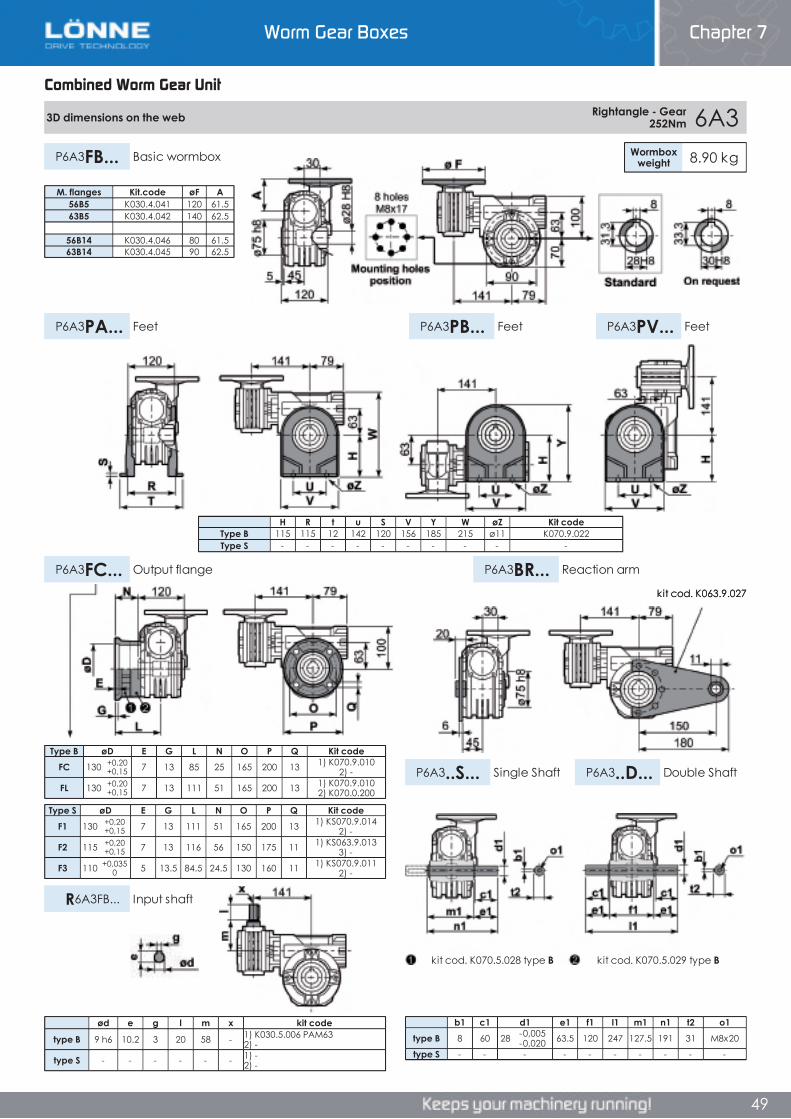
Worm Gear Boxes Chapter 7
49
Combined Worm Gear Unit
3D dimensions on the web Rightangle - Gear 252Nm 6A3
Wormboxweight 8.90 kgP6A3FB... Basic wormbox
P6A3PB... FeetP6A3PA... Feet P6A3PV... Feet
P6A3FC... Output flange P6A3BR... Reaction arm
P6A3..S... Single Shaft P6A3..D... Double Shaft
R6A3FB... Input shaft
Type B øD E G L N O P Q Kit codeFC 130 +0,20
+0,15 7 13 85 25 165 200 13 1) K070.9.010 2) -
FL 130 +0,20+0,15 7 13 111 51 165 200 13 1) K070.9.010
2) K070.0.200
Type S øD E G L N O P Q Kit codeF1 130 +0,20
+0,15 7 13 111 51 165 200 13 1) KS070.9.014 2) -
F2 115 +0,20+0,15 7 13 116 56 150 175 11 1) KS063.9.013
3) -
F3 110 +0,0350 5 13.5 84.5 24.5 130 160 11 1) KS070.9.011
2) -
b1 c1 d1 e1 f1 l1 m1 n1 t2 o1type B 8 60 28 -0,005
-0,020 63.5 120 247 127.5 191 31 M8x20
type S - - - - - - - - - -
H R t u S V Y W øZ Kit codeType B 115 115 12 142 120 156 185 215 ø11 K070.9.022Type S - - - - - - - - - -
ød e g l m x kit code
type B 9 h6 10.2 3 20 58 - 1) K030.5.006 PAM63 2) -
type S - - - - - - 1) -2) -
M. flanges Kit.code øF A56B5 K030.4.041 120 61.563B5 K030.4.042 140 62.5
56B14 K030.4.046 80 61.563B14 K030.4.045 90 62.5
kit cod. K070.5.029 type Bkit cod. K070.5.028 type B
kit cod. K063.9.027
Combined Worm Gear Unit
Chapter 7Worm Gear Boxes
Combined Worm Gear Unit
3D dimensions on the web Rightangle - Gear 252Nm 6A3
Wormboxweight 8.90 kgP6A3FB... Basic wormbox
P6A3PB... FeetP6A3PA... Feet P6A3PV... Feet
P6A3FC... Output flange P6A3BR... Reaction arm
P6A3..S... Single Shaft P6A3..D... Double Shaft
R6A3FB... Input shaft
Type B øD E G L N O P Q Kit codeFC 130 +0,20
+0,15 7 13 85 25 165 200 13 1) K070.9.010 2) -
FL 130 +0,20+0,15 7 13 111 51 165 200 13 1) K070.9.010
2) K070.0.200
Type S øD E G L N O P Q Kit codeF1 130 +0,20
+0,15 7 13 111 51 165 200 13 1) KS070.9.014 2) -
F2 115 +0,20+0,15 7 13 116 56 150 175 11 1) KS063.9.013
3) -
F3 110 +0,0350 5 13.5 84.5 24.5 130 160 11 1) KS070.9.011
2) -
b1 c1 d1 e1 f1 l1 m1 n1 t2 o1type B 8 60 28 -0,005
-0,020 63.5 120 247 127.5 191 31 M8x20
type S - - - - - - - - - -
H R t u S V Y W øZ Kit codeType B 115 115 12 142 120 156 185 215 ø11 K070.9.022Type S - - - - - - - - - -
ød e g l m x kit code
type B 9 h6 10.2 3 20 58 - 1) K030.5.006 PAM63 2) -
type S - - - - - - 1) -2) -
M. flanges Kit.code øF A56B5 K030.4.041 120 61.563B5 K030.4.042 140 62.5
56B14 K030.4.046 80 61.563B14 K030.4.045 90 62.5
kit cod. K070.5.029 type Bkit cod. K070.5.028 type B
kit cod. K063.9.027
49
Worm Gear Boxes Chapter 7
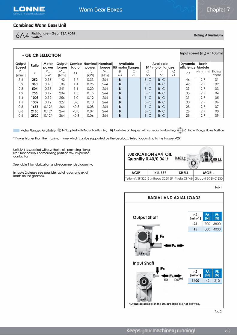
Worm Gear Boxes Chapter 7
50
Combined Worm Gear Unit
6A4 Rightangle - Gear 63A +045 264Nm Rating Alluminium
AGIP KLUBER SHELL MOBILTelium VSF 320 Syntheso D220 EP Tivela Oil WB Glygoyl 30 SHC 630
RADIAL AND AXIAL LOADS
n2[min-1]
FA[N]
FR[N]
1400 42 210
n2[min-1]
FA[N]
FR[N]
25 700 380015 800 4000
• QUICK SELECTION Input speed (n 1) = 1400 min -1
OutputSpeed Ratio Motor
powerOutputtorque
Servicefactor
Nominalpower
Nominaltorque
AvailableB5 motor flanges
AvailableB14 motor flanges
Dynamicefficiency
ToothModule
n2
[min-1] i P1M
[kW]M2M
[Nm] f.s. P1R
[kW]M2R
[Nm]B63
C71
O56
P63
Q71 RD Mn [mm] Ratios
code5.6 252 0.18 142 1.9 0.33 264 B B- C B- C 46 2.7 013.9 360 0.18 186 1.4 0.26 264 B B- C B- C 42 2.7 022.8 504 0.18 241 1.1 0.20 264 B B- C B- C 39 2.7 031.9 756 0.12 204 1.3 0.16 264 B B- C B- C 33 2.7 041.4 1008 0.12 256 1.0 0.12 264 B B- C B- C 31 2.7 051.1 1332 0.12 327 0.8 0.10 264 B B- C B- C 30 2.7 060.8 1656 0.12* 264 <0.8 0.08 264 B B- C B- C 28 2.7 070.6 2160 0.12* 264 <0.8 0.07 264 B B- C B- C 26 2.7 080.6 2520 0.12* 264 <0.8 0.06 264 B B- C B- C 25 2.7 09
* Power higher than the maximum one which can be supported by the gearbox. Select according to the torque M2R
Unit 6A4 is supplied with synthetic oil, providing “long life” lubrication. For mounting position V5- V6 please contact us.
See table 1 for lubrication and recommended quantity.
In table 2 please see possible radial loads and axial loads on the gearbox.
Tab 2
Tab 1
LUBRICATION 6A4 OIL Quantity 0.40/0.06 Lt
Input Shaft
Output Shaft
*Strong axial loads in the DX direction are not allowed.
Motor Flanges Available C) Motor Flange Holes PositionB) Available on Request without reduction bushingB) Supplied with Reduction Bushing
Combined Worm Gear Unit
Chapter 7Worm Gear Boxes
Combined Worm Gear Unit
6A4 Rightangle - Gear 63A +045 264Nm Rating Alluminium
AGIP KLUBER SHELL MOBILTelium VSF 320 Syntheso D220 EP Tivela Oil WB Glygoyl 30 SHC 630
RADIAL AND AXIAL LOADS
n2[min-1]
FA[N]
FR[N]
1400 42 210
n2[min-1]
FA[N]
FR[N]
25 700 380015 800 4000
• QUICK SELECTION Input speed (n 1) = 1400 min -1
OutputSpeed Ratio Motor
powerOutputtorque
Servicefactor
Nominalpower
Nominaltorque
AvailableB5 motor flanges
AvailableB14 motor flanges
Dynamicefficiency
ToothModule
n2
[min-1] i P1M
[kW]M2M
[Nm] f.s. P1R
[kW]M2R
[Nm]B63
C71
O56
P63
Q71 RD Mn [mm] Ratios
code5.6 252 0.18 142 1.9 0.33 264 B B- C B- C 46 2.7 013.9 360 0.18 186 1.4 0.26 264 B B- C B- C 42 2.7 022.8 504 0.18 241 1.1 0.20 264 B B- C B- C 39 2.7 031.9 756 0.12 204 1.3 0.16 264 B B- C B- C 33 2.7 041.4 1008 0.12 256 1.0 0.12 264 B B- C B- C 31 2.7 051.1 1332 0.12 327 0.8 0.10 264 B B- C B- C 30 2.7 060.8 1656 0.12* 264 <0.8 0.08 264 B B- C B- C 28 2.7 070.6 2160 0.12* 264 <0.8 0.07 264 B B- C B- C 26 2.7 080.6 2520 0.12* 264 <0.8 0.06 264 B B- C B- C 25 2.7 09
* Power higher than the maximum one which can be supported by the gearbox. Select according to the torque M2R
Unit 6A4 is supplied with synthetic oil, providing “long life” lubrication. For mounting position V5- V6 please contact us.
See table 1 for lubrication and recommended quantity.
In table 2 please see possible radial loads and axial loads on the gearbox.
Tab 2
Tab 1
LUBRICATION 6A4 OIL Quantity 0.40/0.06 Lt
Input Shaft
Output Shaft
*Strong axial loads in the DX direction are not allowed.
Motor Flanges Available C) Motor Flange Holes PositionB) Available on Request without reduction bushingB) Supplied with Reduction Bushing
50
6A4 Rightangle - Gear 63A +045 264Nm Rating Alluminium
AGIP KLUBER SHELL MOBILTelium VSF 320 Syntheso D220 EP Tivela Oil WB Glygoyl 30 SHC 630
RADIAL AND AXIAL LOADS
n2[min-1]
FA[N]
FR[N]
1400 42 210
n2[min-1]
FA[N]
FR[N]
25 700 380015 800 4000
• QUICK SELECTION Input speed (n 1) = 1400 min -1
OutputSpeed Ratio Motor
powerOutputtorque
Servicefactor
Nominalpower
Nominaltorque
AvailableB5 motor flanges
AvailableB14 motor flanges
Dynamicefficiency
ToothModule
n2
[min-1] i P1M
[kW]M2M
[Nm] f.s. P1R
[kW]M2R
[Nm]B63
C71
O56
P63
Q71 RD Mn [mm] Ratios
code5.6 252 0.18 142 1.9 0.33 264 B B- C B- C 46 2.7 013.9 360 0.18 186 1.4 0.26 264 B B- C B- C 42 2.7 022.8 504 0.18 241 1.1 0.20 264 B B- C B- C 39 2.7 031.9 756 0.12 204 1.3 0.16 264 B B- C B- C 33 2.7 041.4 1008 0.12 256 1.0 0.12 264 B B- C B- C 31 2.7 051.1 1332 0.12 327 0.8 0.10 264 B B- C B- C 30 2.7 060.8 1656 0.12* 264 <0.8 0.08 264 B B- C B- C 28 2.7 070.6 2160 0.12* 264 <0.8 0.07 264 B B- C B- C 26 2.7 080.6 2520 0.12* 264 <0.8 0.06 264 B B- C B- C 25 2.7 09
* Power higher than the maximum one which can be supported by the gearbox. Select according to the torque M2R
Unit 6A4 is supplied with synthetic oil, providing “long life” lubrication. For mounting position V5- V6 please contact us.
See table 1 for lubrication and recommended quantity.
In table 2 please see possible radial loads and axial loads on the gearbox.
Tab 2
Tab 1
LUBRICATION 6A4 OIL Quantity 0.40/0.06 Lt
Input Shaft
Output Shaft
*Strong axial loads in the DX direction are not allowed.
Motor Flanges Available C) Motor Flange Holes PositionB) Available on Request without reduction bushingB) Supplied with Reduction Bushing
Worm Gear Boxes Chapter 7
50
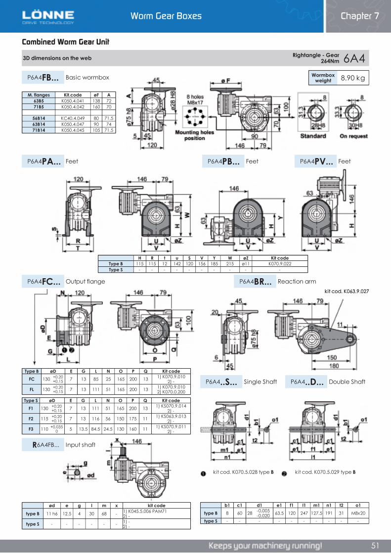
Worm Gear Boxes Chapter 7
51
Combined Worm Gear Unit
3D dimensions on the web Rightangle - Gear 264Nm 6A4
Wormboxweight 8.90 kgP6A4FB... Basic wormbox
P6A4PB... FeetP6A4PA... Feet P6A4PV... Feet
P6A4FC... Output flange P6A4BR... Reaction arm
P6A4..S... Single Shaft P6A4..D... Double Shaft
R6A4FB... Input shaft
Type B øD E G L N O P Q Kit codeFC 130 +0,20
+0,15 7 13 85 25 165 200 13 1) K070.9.010 2) -
FL 130 +0,20+0,15 7 13 111 51 165 200 13 1) K070.9.010
2) K070.0.200
Type S øD E G L N O P Q Kit codeF1 130 +0,20
+0,15 7 13 111 51 165 200 13 1) KS070.9.014 2) -
F2 115 +0,20+0,15 7 13 116 56 150 175 11 1) KS063.9.013
2) -
F3 110 +0,0350 5 13.5 84.5 24.5 130 160 11 1) KS070.9.011
2) -
b1 c1 d1 e1 f1 l1 m1 n1 t2 o1type B 8 60 28 -0,005
-0,020 63.5 120 247 127.5 191 31 M8x20
type S - - - - - - - - - -
ød e g l m x kit code
type B 11 h6 12.5 4 30 68 - 1) K045.5.006 PAM71 2) -
type S - - - - - - 1) -2) -
M. flanges Kit.code øF A63B5 K050.4.041 138 7271B5 K050.4.042 160 70
56B14 KC40.4.049 80 71.563B14 K050.4.047 90 7471B14 K050.4.045 105 71.5
H R t u S V Y W øZ Kit codeType B 115 115 12 142 120 156 185 215 ø11 K070.9.022Type S - - - - - - - - - -
kit cod. K070.5.029 type Bkit cod. K070.5.028 type B
kit cod. K063.9.027
Combined Worm Gear Unit
Chapter 7Worm Gear Boxes
Combined Worm Gear Unit
3D dimensions on the web Rightangle - Gear 264Nm 6A4
Wormboxweight 8.90 kgP6A4FB... Basic wormbox
P6A4PB... FeetP6A4PA... Feet P6A4PV... Feet
P6A4FC... Output flange P6A4BR... Reaction arm
P6A4..S... Single Shaft P6A4..D... Double Shaft
R6A4FB... Input shaft
Type B øD E G L N O P Q Kit codeFC 130 +0,20
+0,15 7 13 85 25 165 200 13 1) K070.9.010 2) -
FL 130 +0,20+0,15 7 13 111 51 165 200 13 1) K070.9.010
2) K070.0.200
Type S øD E G L N O P Q Kit codeF1 130 +0,20
+0,15 7 13 111 51 165 200 13 1) KS070.9.014 2) -
F2 115 +0,20+0,15 7 13 116 56 150 175 11 1) KS063.9.013
2) -
F3 110 +0,0350 5 13.5 84.5 24.5 130 160 11 1) KS070.9.011
2) -
b1 c1 d1 e1 f1 l1 m1 n1 t2 o1type B 8 60 28 -0,005
-0,020 63.5 120 247 127.5 191 31 M8x20
type S - - - - - - - - - -
ød e g l m x kit code
type B 11 h6 12.5 4 30 68 - 1) K045.5.006 PAM71 2) -
type S - - - - - - 1) -2) -
M. flanges Kit.code øF A63B5 K050.4.041 138 7271B5 K050.4.042 160 70
56B14 KC40.4.049 80 71.563B14 K050.4.047 90 7471B14 K050.4.045 105 71.5
H R t u S V Y W øZ Kit codeType B 115 115 12 142 120 156 185 215 ø11 K070.9.022Type S - - - - - - - - - -
kit cod. K070.5.029 type Bkit cod. K070.5.028 type B
kit cod. K063.9.027
51
Worm Gear Boxes Chapter 7
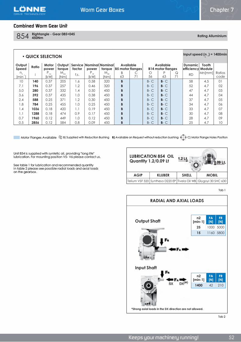
Worm Gear Boxes Chapter 7
52
Combined Worm Gear Unit
854 Rightangle - Gear 085+045 450Nm Rating Alluminium
AGIP KLUBER SHELL MOBILTelium VSF 320 Syntheso D220 EP Tivela Oil WB Glygoyl 30 SHC 630
RADIAL AND AXIAL LOADS
n2[min-1]
FA[N]
FR[N]
1400 42 210
n2[min-1]
FA[N]
FR[N]
25 1000 500015 1160 5800
• QUICK SELECTION Input speed (n 1) = 1400 min -1
OutputSpeed Ratio Motor
powerOutputtorque
Servicefactor
Nominalpower
Nominaltorque
AvailableB5 motor flanges
AvailableB14 motor flanges
Dynamicefficiency
ToothModule
n2
[min-1] i P1M
[kW]M2M
[Nm] f.s. P1R
[kW]M2R
[Nm]B63
C71
O56
P63
Q71 RD Mn [mm] Ratios
code10 140 0.37 205 1.6 0.58 320 B B- C B- C 58 4.5 017.1 196 0.37 257 1.2 0.46 320 B B- C B- C 52 4.7 025.0 280 0.37 332 1.4 0.50 450 B B- C B- C 47 4.7 033.6 392 0.37 435 1.0 0.38 450 B B- C B- C 44 4.7 042.4 588 0.25 371 1.2 0.30 450 B B- C B- C 37 4.7 051.8 784 0.25 455 1.0 0.25 450 B B- C B- C 34 4.7 061.4 1036 0.18 420 1.1 0.19 450 B B- C B- C 33 4.7 071.1 1288 0.18 474 0.9 0.17 450 B B- C B- C 30 4.7 080.7 1960 0.12 449 1.0 0.12 450 B B- C B- C 28 4.7 090.5 2856 0.12 584 0.8 0.09 450 B B- C B- C 25 4.7 10
Unit 854 is supplied with syntetic oil, providing "long life" lubrication. For mounting position V5- V6 please contact us.
See table 1 for lubrication and recommended quantity In table 2 please see possible radial loads and axial loads on the gearbox.
Tab 2
Tab 1
LUBRICATION 854 OIL Quantity 1.2/0.09 Lt
Input Shaft
Output Shaft
*Strong axial loads in the DX direction are not allowed.
B) Supplied with Reduction Bushing B) Available on Request without reduction bushing C) Motor Flange Holes PositionMotor Flanges Available
Combined Worm Gear Unit
Chapter 7Worm Gear Boxes
52
854 Rightangle - Gear 085+045 450Nm Rating Alluminium
AGIP KLUBER SHELL MOBILTelium VSF 320 Syntheso D220 EP Tivela Oil WB Glygoyl 30 SHC 630
RADIAL AND AXIAL LOADS
n2[min-1]
FA[N]
FR[N]
1400 42 210
n2[min-1]
FA[N]
FR[N]
25 1000 500015 1160 5800
• QUICK SELECTION Input speed (n 1) = 1400 min -1
OutputSpeed Ratio Motor
powerOutputtorque
Servicefactor
Nominalpower
Nominaltorque
AvailableB5 motor flanges
AvailableB14 motor flanges
Dynamicefficiency
ToothModule
n2
[min-1] i P1M
[kW]M2M
[Nm] f.s. P1R
[kW]M2R
[Nm]B63
C71
O56
P63
Q71 RD Mn [mm] Ratios
code10 140 0.37 205 1.6 0.58 320 B B- C B- C 58 4.5 017.1 196 0.37 257 1.2 0.46 320 B B- C B- C 52 4.7 025.0 280 0.37 332 1.4 0.50 450 B B- C B- C 47 4.7 033.6 392 0.37 435 1.0 0.38 450 B B- C B- C 44 4.7 042.4 588 0.25 371 1.2 0.30 450 B B- C B- C 37 4.7 051.8 784 0.25 455 1.0 0.25 450 B B- C B- C 34 4.7 061.4 1036 0.18 420 1.1 0.19 450 B B- C B- C 33 4.7 071.1 1288 0.18 474 0.9 0.17 450 B B- C B- C 30 4.7 080.7 1960 0.12 449 1.0 0.12 450 B B- C B- C 28 4.7 090.5 2856 0.12 584 0.8 0.09 450 B B- C B- C 25 4.7 10
Unit 854 is supplied with syntetic oil, providing "long life" lubrication. For mounting position V5- V6 please contact us.
See table 1 for lubrication and recommended quantity In table 2 please see possible radial loads and axial loads on the gearbox.
Tab 2
Tab 1
LUBRICATION 854 OIL Quantity 1.2/0.09 Lt
Input Shaft
Output Shaft
*Strong axial loads in the DX direction are not allowed.
B) Supplied with Reduction Bushing B) Available on Request without reduction bushing C) Motor Flange Holes PositionMotor Flanges Available
Worm Gear Boxes Chapter 7
52
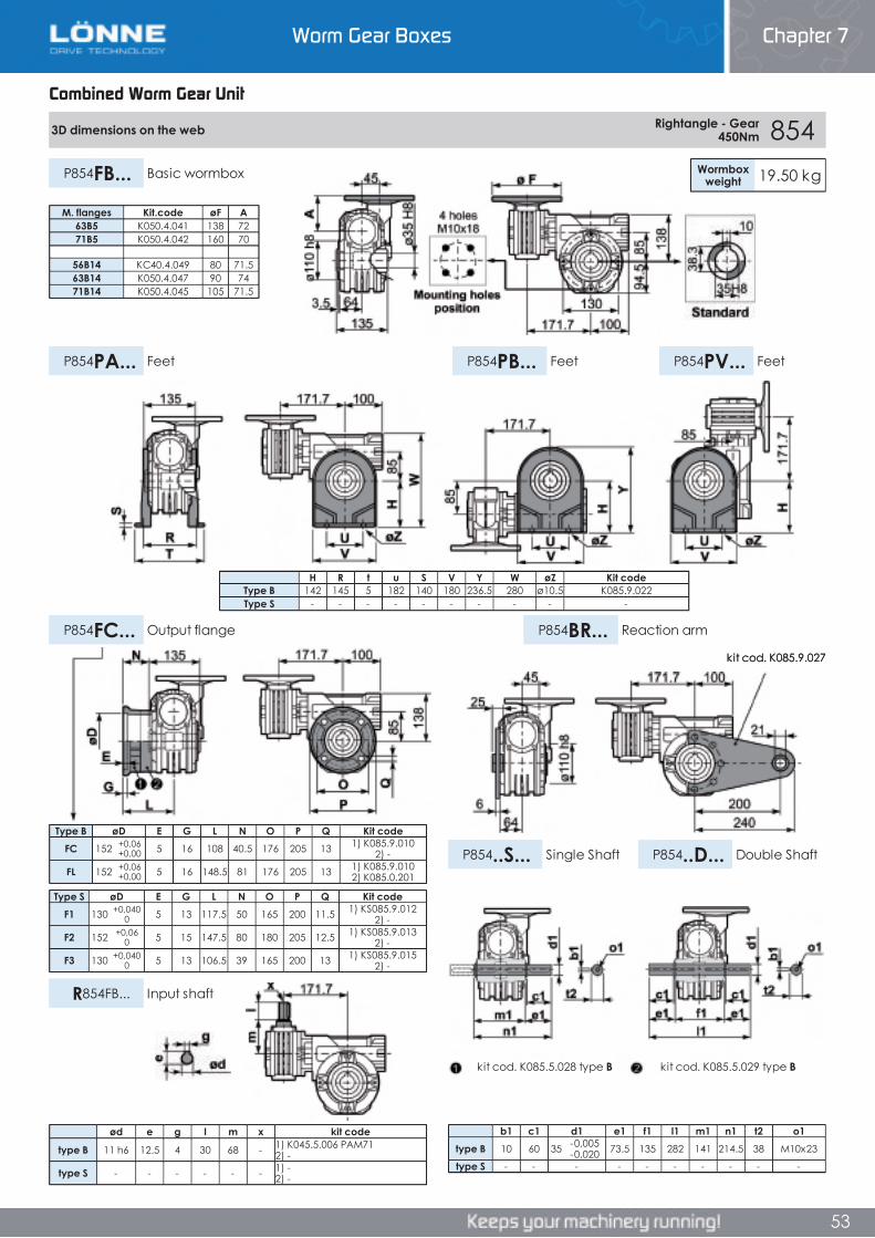
Worm Gear Boxes Chapter 7
53
Combined Worm Gear Unit
3D dimensions on the web Rightangle - Gear 450Nm 854
Wormboxweight 19.50 kgP854FB... Basic wormbox
P854PB... FeetP854PA... Feet P854PV... Feet
P854FC... Output flange P854BR... Reaction arm
P854..S... Single Shaft P854..D... Double Shaft
R854FB... Input shaft
Type B øD E G L N O P Q Kit codeFC 152 +0,06
+0,00 5 16 108 40.5 176 205 13 1) K085.9.010 2) -
FL 152 +0,06+0,00 5 16 148.5 81 176 205 13 1) K085.9.010
2) K085.0.201
Type S øD E G L N O P Q Kit codeF1 130 +0,040
0 5 13 117.5 50 165 200 11.5 1) KS085.9.012 2) -
F2 152 +0,060 5 15 147.5 80 180 205 12.5 1) KS085.9.013
2) -
F3 130 +0,0400 5 13 106.5 39 165 200 13 1) KS085.9.015
2) -
b1 c1 d1 e1 f1 l1 m1 n1 t2 o1type B 10 60 35 -0,005
-0,020 73.5 135 282 141 214.5 38 M10x23
type S - - - - - - - - - -
H R t u S V Y W øZ Kit codeType B 142 145 5 182 140 180 236.5 280 ø10.5 K085.9.022Type S - - - - - - - - - -
M. flanges Kit.code øF A63B5 K050.4.041 138 7271B5 K050.4.042 160 70
56B14 KC40.4.049 80 71.563B14 K050.4.047 90 7471B14 K050.4.045 105 71.5
ød e g l m x kit code
type B 11 h6 12.5 4 30 68 - 1) K045.5.006 PAM71 2) -
type S - - - - - - 1) -2) -
kit cod. K085.5.029 type Bkit cod. K085.5.028 type B
kit cod. K085.9.027
Combined Worm Gear Unit
Chapter 7Worm Gear Boxes
Combined Worm Gear Unit
3D dimensions on the web Rightangle - Gear 450Nm 854
Wormboxweight 19.50 kgP854FB... Basic wormbox
P854PB... FeetP854PA... Feet P854PV... Feet
P854FC... Output flange P854BR... Reaction arm
P854..S... Single Shaft P854..D... Double Shaft
R854FB... Input shaft
Type B øD E G L N O P Q Kit codeFC 152 +0,06
+0,00 5 16 108 40.5 176 205 13 1) K085.9.010 2) -
FL 152 +0,06+0,00 5 16 148.5 81 176 205 13 1) K085.9.010
2) K085.0.201
Type S øD E G L N O P Q Kit codeF1 130 +0,040
0 5 13 117.5 50 165 200 11.5 1) KS085.9.012 2) -
F2 152 +0,060 5 15 147.5 80 180 205 12.5 1) KS085.9.013
2) -
F3 130 +0,0400 5 13 106.5 39 165 200 13 1) KS085.9.015
2) -
b1 c1 d1 e1 f1 l1 m1 n1 t2 o1type B 10 60 35 -0,005
-0,020 73.5 135 282 141 214.5 38 M10x23
type S - - - - - - - - - -
H R t u S V Y W øZ Kit codeType B 142 145 5 182 140 180 236.5 280 ø10.5 K085.9.022Type S - - - - - - - - - -
M. flanges Kit.code øF A63B5 K050.4.041 138 7271B5 K050.4.042 160 70
56B14 KC40.4.049 80 71.563B14 K050.4.047 90 7471B14 K050.4.045 105 71.5
ød e g l m x kit code
type B 11 h6 12.5 4 30 68 - 1) K045.5.006 PAM71 2) -
type S - - - - - - 1) -2) -
kit cod. K085.5.029 type Bkit cod. K085.5.028 type B
kit cod. K085.9.027
53
Worm Gear Boxes Chapter 7
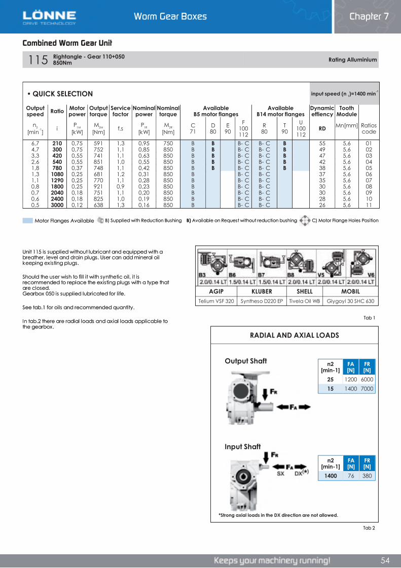
Worm Gear Boxes Chapter 7
54
Combined Worm Gear Unit
115 Rightangle - Gear 110+050 850Nm Rating Alluminium
AGIP KLUBER SHELL MOBILTelium VSF 320 Syntheso D220 EP Tivela Oil WB Glygoyl 30 SHC 630
RADIAL AND AXIAL LOADS
n2[min-1]
FA[N]
FR[N]
1400 76 380
n2[min-1]
FA[N]
FR[N]
25 1200 600015 1400 7000
• QUICK SELECTION input speed (n 1)=1400 min-1
Outputspeed Ratio Motor
powerOutputtorque
Servicefactor
Nominalpower
Nominaltorque
AvailableB5 motor flanges
AvailableB14 motor flanges
Dynamiceffiency
ToothModule
n2
[min-1] i P1M
[kW]M2M
[Nm] f.s P1R
[kW]M2R
[Nm]C71
D80
E90
F100112
R80
T90
U100112
RD Mn [mm] Ratioscode
6,7 210 0,75 591 1,3 0,95 750 B B B- C B- C B 55 5,6 014,7 300 0,75 752 1,1 0,85 850 B B B- C B- C B 49 5,6 023,3 420 0,55 741 1,1 0,63 850 B B B- C B- C B 47 5,6 032,6 540 0,55 851 1,0 0,55 850 B B B- C B- C B 42 5,6 041,8 780 0,37 748 1,1 0,42 850 B B B- C B- C B 38 5,6 051,3 1080 0,25 681 1,2 0,31 850 B B- C B- C 37 5,6 061,1 1290 0,25 770 1,1 0,28 850 B B- C B- C 35 5,6 070,8 1800 0,25 921 0,9 0,23 850 B B- C B- C 30 5,6 080,7 2040 0,18 751 1,1 0,20 850 B B- C B- C 30 5,6 090,6 2400 0,18 825 1,0 0,19 850 B B- C B- C 28 5,6 100,5 3000 0,12 638 1,3 0,16 850 B B- C B- C 26 5,6 11
Unit 115 is supplied without lubricant and equipped with a breather, level and drain plugs. User can add mineral oil keeping existing plugs.
Should the user wish to fill it with synthetic oil, it is recommended to replace the existing plugs with a type that are closed. Gearbox 050 is supplied lubricated for life.
See tab.1 for oils and recommended quantity.
In tab.2 there are radial loads and axial loads applicable to the gearbox.
Tab 2
Tab 1
Input Shaft
Output Shaft
*Strong axial loads in the DX direction are not allowed.
B) Supplied with Reduction Bushing B) Available on Request without reduction bushing C) Motor Flange Holes PositionMotor Flanges Available
Combined Worm Gear Unit
Chapter 7Worm Gear Boxes
54
115 Rightangle - Gear 110+050 850Nm Rating Alluminium
AGIP KLUBER SHELL MOBILTelium VSF 320 Syntheso D220 EP Tivela Oil WB Glygoyl 30 SHC 630
RADIAL AND AXIAL LOADS
n2[min-1]
FA[N]
FR[N]
1400 76 380
n2[min-1]
FA[N]
FR[N]
25 1200 600015 1400 7000
• QUICK SELECTION input speed (n 1)=1400 min-1
Outputspeed Ratio Motor
powerOutputtorque
Servicefactor
Nominalpower
Nominaltorque
AvailableB5 motor flanges
AvailableB14 motor flanges
Dynamiceffiency
ToothModule
n2
[min-1] i P1M
[kW]M2M
[Nm] f.s P1R
[kW]M2R
[Nm]C71
D80
E90
F100112
R80
T90
U100112
RD Mn [mm] Ratioscode
6,7 210 0,75 591 1,3 0,95 750 B B B- C B- C B 55 5,6 014,7 300 0,75 752 1,1 0,85 850 B B B- C B- C B 49 5,6 023,3 420 0,55 741 1,1 0,63 850 B B B- C B- C B 47 5,6 032,6 540 0,55 851 1,0 0,55 850 B B B- C B- C B 42 5,6 041,8 780 0,37 748 1,1 0,42 850 B B B- C B- C B 38 5,6 051,3 1080 0,25 681 1,2 0,31 850 B B- C B- C 37 5,6 061,1 1290 0,25 770 1,1 0,28 850 B B- C B- C 35 5,6 070,8 1800 0,25 921 0,9 0,23 850 B B- C B- C 30 5,6 080,7 2040 0,18 751 1,1 0,20 850 B B- C B- C 30 5,6 090,6 2400 0,18 825 1,0 0,19 850 B B- C B- C 28 5,6 100,5 3000 0,12 638 1,3 0,16 850 B B- C B- C 26 5,6 11
Unit 115 is supplied without lubricant and equipped with a breather, level and drain plugs. User can add mineral oil keeping existing plugs.
Should the user wish to fill it with synthetic oil, it is recommended to replace the existing plugs with a type that are closed. Gearbox 050 is supplied lubricated for life.
See tab.1 for oils and recommended quantity.
In tab.2 there are radial loads and axial loads applicable to the gearbox.
Tab 2
Tab 1
Input Shaft
Output Shaft
*Strong axial loads in the DX direction are not allowed.
B) Supplied with Reduction Bushing B) Available on Request without reduction bushing C) Motor Flange Holes PositionMotor Flanges Available
Worm Gear Boxes Chapter 7
54
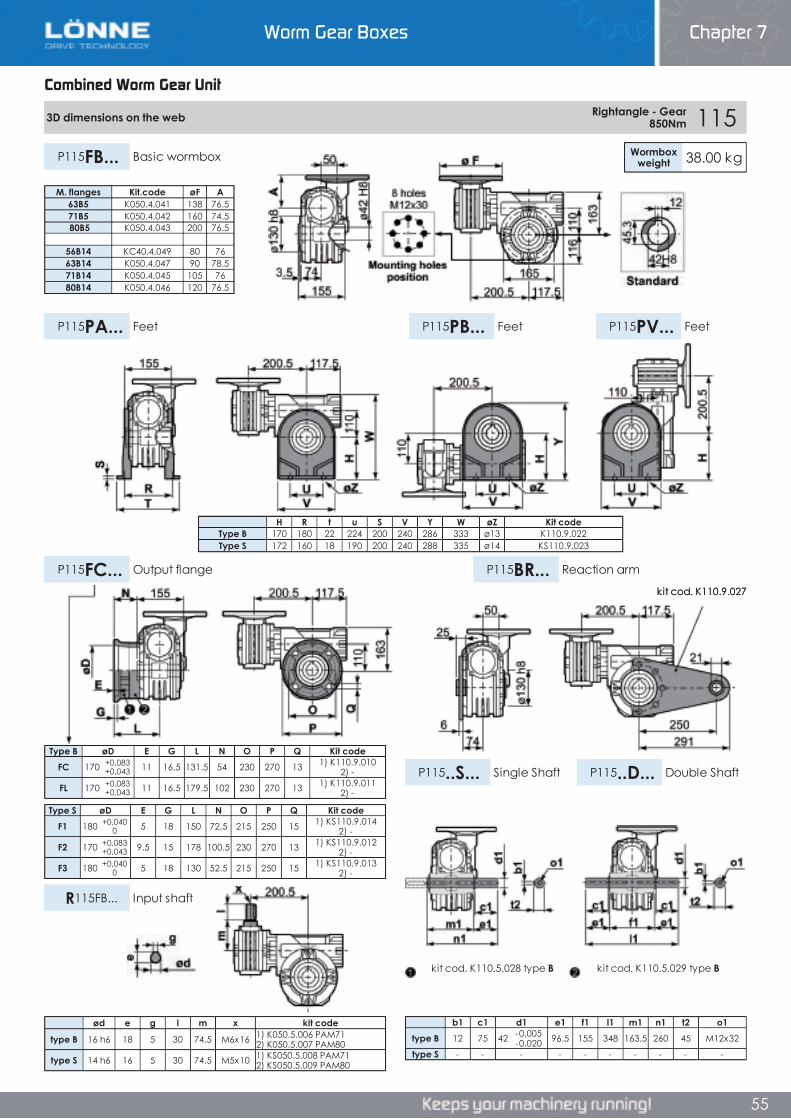
Worm Gear Boxes Chapter 7
54
Combined Worm Gear Unit
115 Rightangle - Gear 110+050 850Nm Rating Alluminium
AGIP KLUBER SHELL MOBILTelium VSF 320 Syntheso D220 EP Tivela Oil WB Glygoyl 30 SHC 630
RADIAL AND AXIAL LOADS
n2[min-1]
FA[N]
FR[N]
1400 76 380
n2[min-1]
FA[N]
FR[N]
25 1200 600015 1400 7000
• QUICK SELECTION input speed (n 1)=1400 min-1
Outputspeed Ratio Motor
powerOutputtorque
Servicefactor
Nominalpower
Nominaltorque
AvailableB5 motor flanges
AvailableB14 motor flanges
Dynamiceffiency
ToothModule
n2
[min-1] i P1M
[kW]M2M
[Nm] f.s P1R
[kW]M2R
[Nm]C71
D80
E90
F100112
R80
T90
U100112
RD Mn [mm] Ratioscode
6,7 210 0,75 591 1,3 0,95 750 B B B- C B- C B 55 5,6 014,7 300 0,75 752 1,1 0,85 850 B B B- C B- C B 49 5,6 023,3 420 0,55 741 1,1 0,63 850 B B B- C B- C B 47 5,6 032,6 540 0,55 851 1,0 0,55 850 B B B- C B- C B 42 5,6 041,8 780 0,37 748 1,1 0,42 850 B B B- C B- C B 38 5,6 051,3 1080 0,25 681 1,2 0,31 850 B B- C B- C 37 5,6 061,1 1290 0,25 770 1,1 0,28 850 B B- C B- C 35 5,6 070,8 1800 0,25 921 0,9 0,23 850 B B- C B- C 30 5,6 080,7 2040 0,18 751 1,1 0,20 850 B B- C B- C 30 5,6 090,6 2400 0,18 825 1,0 0,19 850 B B- C B- C 28 5,6 100,5 3000 0,12 638 1,3 0,16 850 B B- C B- C 26 5,6 11
Unit 115 is supplied without lubricant and equipped with a breather, level and drain plugs. User can add mineral oil keeping existing plugs.
Should the user wish to fill it with synthetic oil, it is recommended to replace the existing plugs with a type that are closed. Gearbox 050 is supplied lubricated for life.
See tab.1 for oils and recommended quantity.
In tab.2 there are radial loads and axial loads applicable to the gearbox.
Tab 2
Tab 1
Input Shaft
Output Shaft
*Strong axial loads in the DX direction are not allowed.
B) Supplied with Reduction Bushing B) Available on Request without reduction bushing C) Motor Flange Holes PositionMotor Flanges Available
Combined Worm Gear Unit
Chapter 7Worm Gear Boxes
54
115 Rightangle - Gear 110+050 850Nm Rating Alluminium
AGIP KLUBER SHELL MOBILTelium VSF 320 Syntheso D220 EP Tivela Oil WB Glygoyl 30 SHC 630
RADIAL AND AXIAL LOADS
n2[min-1]
FA[N]
FR[N]
1400 76 380
n2[min-1]
FA[N]
FR[N]
25 1200 600015 1400 7000
• QUICK SELECTION input speed (n 1)=1400 min-1
Outputspeed Ratio Motor
powerOutputtorque
Servicefactor
Nominalpower
Nominaltorque
AvailableB5 motor flanges
AvailableB14 motor flanges
Dynamiceffiency
ToothModule
n2
[min-1] i P1M
[kW]M2M
[Nm] f.s P1R
[kW]M2R
[Nm]C71
D80
E90
F100112
R80
T90
U100112
RD Mn [mm] Ratioscode
6,7 210 0,75 591 1,3 0,95 750 B B B- C B- C B 55 5,6 014,7 300 0,75 752 1,1 0,85 850 B B B- C B- C B 49 5,6 023,3 420 0,55 741 1,1 0,63 850 B B B- C B- C B 47 5,6 032,6 540 0,55 851 1,0 0,55 850 B B B- C B- C B 42 5,6 041,8 780 0,37 748 1,1 0,42 850 B B B- C B- C B 38 5,6 051,3 1080 0,25 681 1,2 0,31 850 B B- C B- C 37 5,6 061,1 1290 0,25 770 1,1 0,28 850 B B- C B- C 35 5,6 070,8 1800 0,25 921 0,9 0,23 850 B B- C B- C 30 5,6 080,7 2040 0,18 751 1,1 0,20 850 B B- C B- C 30 5,6 090,6 2400 0,18 825 1,0 0,19 850 B B- C B- C 28 5,6 100,5 3000 0,12 638 1,3 0,16 850 B B- C B- C 26 5,6 11
Unit 115 is supplied without lubricant and equipped with a breather, level and drain plugs. User can add mineral oil keeping existing plugs.
Should the user wish to fill it with synthetic oil, it is recommended to replace the existing plugs with a type that are closed. Gearbox 050 is supplied lubricated for life.
See tab.1 for oils and recommended quantity.
In tab.2 there are radial loads and axial loads applicable to the gearbox.
Tab 2
Tab 1
Input Shaft
Output Shaft
*Strong axial loads in the DX direction are not allowed.
B) Supplied with Reduction Bushing B) Available on Request without reduction bushing C) Motor Flange Holes PositionMotor Flanges Available
Worm Gear Boxes Chapter 7
54
Worm Gear Boxes Chapter 7
55
Combined Worm Gear Unit
3D dimensions on the web Rightangle - Gear 850Nm 115
Wormboxweight 38.00 kgP115FB... Basic wormbox
P115PB... FeetP115PA... Feet P115PV... Feet
P115FC... Output flange P115BR... Reaction arm
P115..S... Single Shaft P115..D... Double Shaft
R115FB... Input shaft
Type B øD E G L N O P Q Kit codeFC 170 +0,083
+0,043 11 16.5 131.5 54 230 270 13 1) K110.9.010 2) -
FL 170 +0,083+0,043 11 16.5 179.5 102 230 270 13 1) K110.9.011
2) -
Type S øD E G L N O P Q Kit codeF1 180 +0,040
0 5 18 150 72.5 215 250 15 1) KS110.9.014 2) -
F2 170 +0,083+0,043 9.5 15 178 100.5 230 270 13 1) KS110.9.012
2) -
F3 180 +0,0400 5 18 130 52.5 215 250 15 1) KS110.9.013
2) -
b1 c1 d1 e1 f1 l1 m1 n1 t2 o1type B 12 75 42 -0,005
-0,020 96.5 155 348 163.5 260 45 M12x32
type S - - - - - - - - - -
H R t u S V Y W øZ Kit codeType B 170 180 22 224 200 240 286 333 ø13 K110.9.022Type S 172 160 18 190 200 240 288 335 ø14 KS110.9.023
M. flanges Kit.code øF A63B5 K050.4.041 138 76.571B5 K050.4.042 160 74.5 80B5 K050.4.043 200 76.5
56B14 KC40.4.049 80 7663B14 K050.4.047 90 78.571B14 K050.4.045 105 7680B14 K050.4.046 120 76.5
ød e g l m x kit code
type B 16 h6 18 5 30 74.5 M6x16 1) K050.5.006 PAM71 2) K050.5.007 PAM80
type S 14 h6 16 5 30 74.5 M5x10 1) KS050.5.008 PAM71 2) KS050.5.009 PAM80
kit cod. K110.5.029 type Bkit cod. K110.5.028 type B
kit cod. K110.9.027
Combined Worm Gear Unit
Chapter 7Worm Gear Boxes
Combined Worm Gear Unit
3D dimensions on the web Rightangle - Gear 850Nm 115
Wormboxweight 38.00 kgP115FB... Basic wormbox
P115PB... FeetP115PA... Feet P115PV... Feet
P115FC... Output flange P115BR... Reaction arm
P115..S... Single Shaft P115..D... Double Shaft
R115FB... Input shaft
Type B øD E G L N O P Q Kit codeFC 170 +0,083
+0,043 11 16.5 131.5 54 230 270 13 1) K110.9.010 2) -
FL 170 +0,083+0,043 11 16.5 179.5 102 230 270 13 1) K110.9.011
2) -
Type S øD E G L N O P Q Kit codeF1 180 +0,040
0 5 18 150 72.5 215 250 15 1) KS110.9.014 2) -
F2 170 +0,083+0,043 9.5 15 178 100.5 230 270 13 1) KS110.9.012
2) -
F3 180 +0,0400 5 18 130 52.5 215 250 15 1) KS110.9.013
2) -
b1 c1 d1 e1 f1 l1 m1 n1 t2 o1type B 12 75 42 -0,005
-0,020 96.5 155 348 163.5 260 45 M12x32
type S - - - - - - - - - -
H R t u S V Y W øZ Kit codeType B 170 180 22 224 200 240 286 333 ø13 K110.9.022Type S 172 160 18 190 200 240 288 335 ø14 KS110.9.023
M. flanges Kit.code øF A63B5 K050.4.041 138 76.571B5 K050.4.042 160 74.5 80B5 K050.4.043 200 76.5
56B14 KC40.4.049 80 7663B14 K050.4.047 90 78.571B14 K050.4.045 105 7680B14 K050.4.046 120 76.5
ød e g l m x kit code
type B 16 h6 18 5 30 74.5 M6x16 1) K050.5.006 PAM71 2) K050.5.007 PAM80
type S 14 h6 16 5 30 74.5 M5x10 1) KS050.5.008 PAM71 2) KS050.5.009 PAM80
kit cod. K110.5.029 type Bkit cod. K110.5.028 type B
kit cod. K110.9.027
55
Worm Gear Boxes Chapter 7
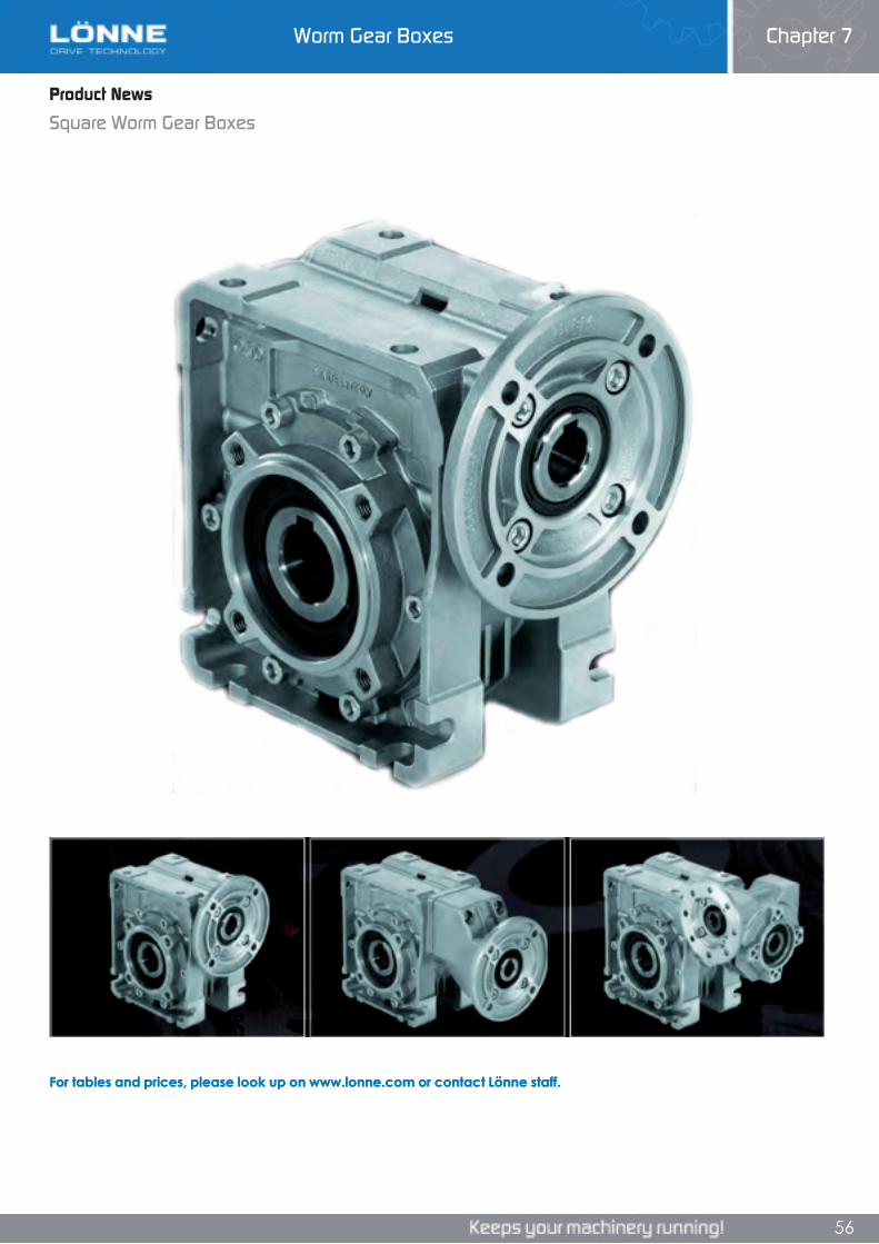
Worm Gear Boxes Chapter 7
56
Product News
Square Worm Gear Boxes
For tables and prices, please look up on www.lonne.com or contact Lönne staff.
Product News
Square Worm Gear Boxes
Chapter 7Worm Gear Boxes
Product News
Square Worm Gear Boxes
For tables and prices, please look up on www.lonne.com or contact Lönne staff.
56
For tables and prices, please look up on www.lonne.com or contact Lönne staff.
56
Worm Gear Boxes Chapter 7
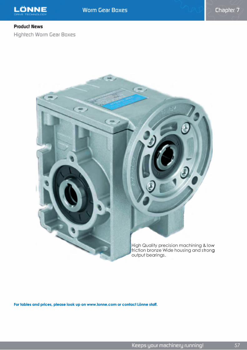
Worm Gear Boxes Chapter 7
56
Product News
Square Worm Gear Boxes
For tables and prices, please look up on www.lonne.com or contact Lönne staff.
Product News
Square Worm Gear Boxes
Chapter 7Worm Gear Boxes
Product News
Square Worm Gear Boxes
For tables and prices, please look up on www.lonne.com or contact Lönne staff.
56
For tables and prices, please look up on www.lonne.com or contact Lönne staff.
56
Worm Gear Boxes Chapter 7 Worm Gear Boxes Chapter 7
57
Product News
Hightech Worm Gear Boxes
For tables and prices, please look up on www.lonne.com or contact Lönne staff.
High Quality precision machining & low friction bronze Wide housing and strong output bearings.
Product News
Hightech Worm Gear Boxes
Chapter 7Worm Gear Boxes
Product News
Hightech Worm Gear Boxes
For tables and prices, please look up on www.lonne.com or contact Lönne staff.
High Quality precision machining & low friction bronze Wide housing and strong output bearings.
57
For tables and prices, please look up on www.lonne.com or contact Lönne staff.
High Quality precision machining & low friction bronze Wide housing and strong output bearings.
57
Worm Gear Boxes Chapter 7
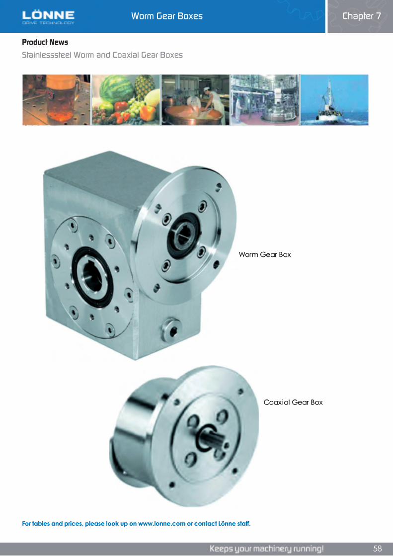
Worm Gear Boxes Chapter 7
58
Product News
Stainlesssteel Worm and Coaxial Gear Boxes
For tables and prices, please look up on www.lonne.com or contact Lönne staff.
Worm Gear Box
Coaxial Gear Box
Product News
Stainlesssteel Worm and Coaxial Gear BoxesProduct News
Stainlesssteel Worm and Coaxial Gear Boxes
For tables and prices, please look up on www.lonne.com or contact Lönne staff.
Worm Gear Box
Coaxial Gear Box
Worm Gear Boxes Chapter 7
58
For tables and prices, please look up on www.lonne.com or contact Lönne staff.
Worm Gear Box
Coaxial Gear Box
58
Worm Gear Boxes Chapter 7
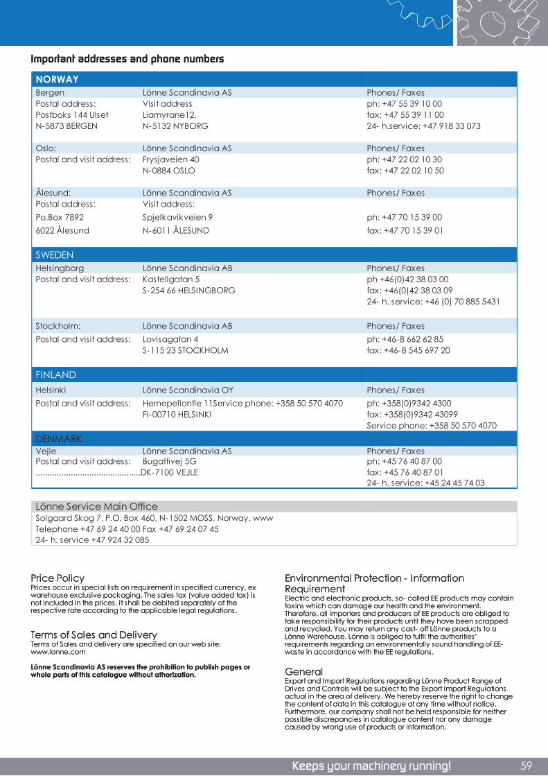
Innledning Bibel rev 3 (vår 2012)
6
Important addresses and phone numbers
NORWAYBergen Lönne Scandinavia AS Phones/ FaxesPostal address: Visit address ph: +47 55 39 10 00Postboks 144 Ulset Liamyrane12, fax: +47 55 39 11 00N-5873 BERGEN N-5132 NYBORG 24- h.service: +47 918 33 073
Oslo: Lönne Scandinavia AS Phones/ FaxesPostal and visit address: Frysjaveien 40 ph: +47 22 02 10 30
N-0884 OSLO fax: +47 22 02 10 50
Ålesund: Lönne Scandinavia AS Phones/ FaxesPostal address: Visit address:Po.Box 7892 Spjelkavikveien 9 ph: +47 70 15 39 006022 Ålesund N-6011 ÅLESUND fax: +47 70 15 39 01
SWEDENHelsingborg Lönne Scandinavia AB Phones/ FaxesPostal and visit address: Kastellgatan 5 ph +46(0)42 38 03 00
S-254 66 HELSINGBORG fax: +46(0)42 38 03 0924- h. service: +46 (0) 70 885 5431
Stockholm: Lönne Scandinavia AB Phones/ FaxesPostal and visit address: Lovisagatan 4 ph: +46-8 662 62 85
S-115 23 STOCKHOLM fax: +46-8 545 697 20
FINLANDHelsinki Lönne Scandinavia OY Phones/ FaxesPostal and visit address: Hernepellontie 11Service phone: +358 50 570 4070 ph: +358(0)9342 4300
FI-00710 HELSINKI fax: +358(0)9342 43099Service phone: +358 50 570 4070
DENMARKVejle Lönne Scandinavia AS Phones/ FaxesPostal and visit address: Bugattivej 5G ph: +45 76 40 87 00.............................................DK-7100 VEJLE fax: +45 76 40 87 01
24- h. service: +45 24 45 74 03
Lönne Service Main OfficeSolgaard Skog 7, P.O. Box 460, N-1502 MOSS, Norway. wwwTelephone +47 69 24 40 00 Fax +47 69 24 07 4524- h. service +47 924 32 085
Environmental Protection - Information Requirement Electric and electronic products, so- called EE products may contain toxins which can damage our health and the environment. Therefore, all importers and producers of EE products are obliged to take responsibility for their products until they have been scrapped and recycled. You may return any cast- off Lönne products to a Lönne Warehouse. Lönne is obliged to fulfil the authorities’ requirements regarding an environmentally sound handling of EE- waste in accordance with the EE regulations.
General Export and Import Regulations regarding Lönne Product Range of Drives and Controls will be subject to the Export Import Regulations actual in the area of delivery. We hereby reserve the right to change the content of data in this catalogue at any time without notice. Furthermore, our company shall not be held responsible for neither possible discrepancies in catalogue content nor any damage caused by wrong use of products or information.
Price Policy Prices occur in special lists on requirement in specified currency, ex warehouse exclusive packaging. The sales tax (value added tax) is not included in the prices. It shall be debited separately at the respective rate according to the applicable legal regulations.
Terms of Sales and Delivery Terms of Sales and delivery are specified on our web site; www.lonne.com
Lönne Scandinavia AS reserves the prohibition to publish pages or whole parts of this catalogue without athorization.
Important addresses and phone numbers
Innledning Bibel rev 3 (vår 2012)
Important addresses and phone numbers
NORWAYBergen Lönne Scandinavia AS Phones/ FaxesPostal address: Visit address ph: +47 55 39 10 00Postboks 144 Ulset Liamyrane12, fax: +47 55 39 11 00N-5873 BERGEN N-5132 NYBORG 24- h.service: +47 918 33 073
Oslo: Lönne Scandinavia AS Phones/ FaxesPostal and visit address: Frysjaveien 40 ph: +47 22 02 10 30
N-0884 OSLO fax: +47 22 02 10 50
Ålesund: Lönne Scandinavia AS Phones/ FaxesPostal address: Visit address:Po.Box 7892 Spjelkavikveien 9 ph: +47 70 15 39 006022 Ålesund N-6011 ÅLESUND fax: +47 70 15 39 01
SWEDENHelsingborg Lönne Scandinavia AB Phones/ FaxesPostal and visit address: Kastellgatan 5 ph +46(0)42 38 03 00
S-254 66 HELSINGBORG fax: +46(0)42 38 03 0924- h. service: +46 (0) 70 885 5431
Stockholm: Lönne Scandinavia AB Phones/ FaxesPostal and visit address: Lovisagatan 4 ph: +46-8 662 62 85
S-115 23 STOCKHOLM fax: +46-8 545 697 20
FINLANDHelsinki Lönne Scandinavia OY Phones/ FaxesPostal and visit address: Hernepellontie 11Service phone: +358 50 570 4070 ph: +358(0)9342 4300
FI-00710 HELSINKI fax: +358(0)9342 43099Service phone: +358 50 570 4070
DENMARKVejle Lönne Scandinavia AS Phones/ FaxesPostal and visit address: Bugattivej 5G ph: +45 76 40 87 00.............................................DK-7100 VEJLE fax: +45 76 40 87 01
24- h. service: +45 24 45 74 03
Lönne Service Main OfficeSolgaard Skog 7, P.O. Box 460, N-1502 MOSS, Norway. wwwTelephone +47 69 24 40 00 Fax +47 69 24 07 4524- h. service +47 924 32 085
Environmental Protection - Information Requirement Electric and electronic products, so- called EE products may contain toxins which can damage our health and the environment. Therefore, all importers and producers of EE products are obliged to take responsibility for their products until they have been scrapped and recycled. You may return any cast- off Lönne products to a Lönne Warehouse. Lönne is obliged to fulfil the authorities’ requirements regarding an environmentally sound handling of EE- waste in accordance with the EE regulations.
General Export and Import Regulations regarding Lönne Product Range of Drives and Controls will be subject to the Export Import Regulations actual in the area of delivery. We hereby reserve the right to change the content of data in this catalogue at any time without notice. Furthermore, our company shall not be held responsible for neither possible discrepancies in catalogue content nor any damage caused by wrong use of products or information.
Price Policy Prices occur in special lists on requirement in specified currency, ex warehouse exclusive packaging. The sales tax (value added tax) is not included in the prices. It shall be debited separately at the respective rate according to the applicable legal regulations.
Terms of Sales and Delivery Terms of Sales and delivery are specified on our web site; www.lonne.com
Lönne Scandinavia AS reserves the prohibition to publish pages or whole parts of this catalogue without athorization.
6
Innledning Bibel rev 3 (vår 2012)
59

Lönne Main Catalogue Chapters: Chapter 1 Electric Motors Chapter 2 Generators Chapter 3 ECOiPM PM Motors Chapter 4 Frequency InvertersChapter 5 Servo ControlsChapter 6 Machine ControlsChapter 7 Worm Gear BoxesChapter 8 Helical Gear BoxesChapter 9 Torque Arm Speed ReducersChapter 10 Planetary Gear BoxesChapter 11 V-belt and V-belt PulleysChapter 12 Timing Belt and Timing Belt PulleysChapter 13 Chains and SprocketsChapter 14 CouplingsChapter 15 Clamping ElementsChapter 16 Disk BrakesChapter 17 BearingsChapter 18 Vibrators
NorwayLönne Scandinavia AS Liamyrane 12, Bergen N-5132 Nyborg BergenTel: +47 55 39 10 00Fax: +47 55 39 11 00Local mail: [email protected] 24-h. service: +47 91 83 30 73
SwedenLönne Scandinavia AB Kastellgatan 5 S-254 66 HelsingborgTel: +46 (0) 42 38 03 00Fax: +46 (0) 42 38 03 09 Local mai: [email protected] 24-h. service: +46 (0) 70 88 55 43 1
DenmarkLönne Scandinavia AS Bugattivej 5G DK-7100 Vejle Tel: +45 (0) 76 40 87 00Fax: +45 (0) 76 40 87 01Local mail: [email protected] 24-h. service: +45 (0) 24 45 74 03
FinlandLönne Scandinavia OY Hernepellontie FI-00560 Helsinki Tel: +358 (0) 9 342 4300Fax: +358 (0) 9 3424 3099 Local mai: [email protected]
Head Office
LönneLönne Scandinavia AS was founded in 1949 in Bergen, Norway. Present board member Mr Terje Lönne entered as second generation, and started the expansion into the Nordic market.
Lönne has specialized within electric motors, generators, frequency inverters, gearboxes, transmissions and bearings. Lönne reference list covers a wide range of customers within on shore, off shore, maritime and marine industries.Step by step the company has grown to become a leading, Nordic supplier within drive technology. Lönne one stop shop concept is a strong force for customers whom operate the total value chain of drive technology components.Lönne is today widely recognized both as a supplier of high quality components and engineered solutions.
Lönne head quarter is located in Bergen, Norway, with subsidiaries in Denmark, Finland and Sweden. The central warehouse, workshop and testing department in Helsingborg provides quick delivery service overnight, to the Nordic market. Smaller express warehouses and workshops are also located in Bergen and Helsinki. See map on the back page for the total Lönne Group.
Lönne Service is a separate part of the Lönne Group. With a total of six workshops in Norway, Lönne Service is specializing in services and repairing of electric motors and generators, both towards on shore and off shore markets.Lönne Service is ranked to have one of the market's largest and most updated machine parks, operated by highly skilled personnel.
Lönne people take pride in every job done, with a high level of professionalism, and really care to ”keep your machinery running!”
Lönne Quality Management System Standards is certified for ISO 9001:2008. For further information, please have a look at our website or feel free to call us!
Products | Solutions | Services