Products for Totally Integrated Automation and Micro ... · 5/38 CPU 412H, CPU 414H, CPU 417H 5/48...
156
Siemens ST 70 · 2009 Brochures For brochures serving as selection guides for SIMATIC products refer to: http://www.siemens.com/simatic/ printmaterial 5/2 Introduction 5/2 S7-400/S7-400H/S7-400F/FH 5/4 Central processing units 5/4 CPU 412 5/10 CPU 414 5/22 CPU 416 5/33 CPU 417 5/38 CPU 412H, CPU 414H, CPU 417H 5/48 CPU 416F 5/56 Sync module for coupling the CPU 41xH 5/57 IF-964 DP PROFIBUS module 5/58 SIPLUS central processing units 5/58 SIPLUS CPU 416, CPU 417 5/59 SIPLUS CPU 414-4H, CPU 417-4H 5/63 Digital modules 5/63 SM 421 digital input modules 5/66 SM 422 digital output modules 5/69 SIPLUS digital modules 5/69 SIPLUS SM 421 digital input modules 5/69 SIPLUS SM 422 digital output modules 5/70 Analog modules 5/70 SM 431 analog input modules 5/79 SM 432 analog output modules 5/81 SIPLUS analog modules 5/81 SIPLUS SM 431 analog input module SIPLUS SM 432 analog output module 5/82 Function modules 5/82 FM 450-1 counter module 5/84 SIPLUS FM 450-1 counter module 5/85 FM 451 positioning module 5/87 FM 452 cam controller 5/89 FM 453 positioning module 5/91 FM 455 controller module 5/94 FM 458-1 DP application module 5/95 FM 458-1 DP basic module 5/97 EXM 438-1 input/output expansion module 5/99 EXM 448 universal communication expansion module 5/100 EXM 448-2 universal communication expansion module 5/101 Accessories for FM 458-1 DP 5/104 SIPLUS DCF 77 radio clock module 5/105 Communication 5/105 CP 440 5/106 CP 441-1, CP 441-2 5/108 CP 443-5 Basic 5/110 CP 443-5 Extended 5/112 CP 443-1 5/115 CP 443-1 Advanced 5/120 Modules for SIMATIC S7-400H 5/120 Y link for S7-400H 5/122 Modules for SIMATIC S7-400F/FH 5/122 IM 153-1/153-2 5/126 SIPLUS IM 153-1/153-2 5/128 Isolation module 5/129 SIPLUS isolating module 5/129 Failsafe input/output modules 5/130 Connection methods 5/130 Front connectors 5/131 Fully modular connection 5/138 Flexible connection 5/139 Racks 5/139 Racks 5/141 Fan subassembly 5/142 Expansion racks 5/143 Interface modules 5/143 IM 460-0 5/144 IM 461-0 5/145 IM 460-1 5/146 IM 461-1 5/147 IM 460-3 5/148 IM 461-3 5/149 IM 463-2 5/150 Power supplies 5/154 Accessories 5/154 Labeling sheets 5/155 Spare parts SIMATIC S7-400 © Siemens AG 2008
Transcript of Products for Totally Integrated Automation and Micro ... · 5/38 CPU 412H, CPU 414H, CPU 417H 5/48...

Siemens ST 70 · 2009
Brochures
For brochures serving as selection guides for SIMATIC products refer to:
http://www.siemens.com/simatic/printmaterial
5/2 Introduction5/2 S7-400/S7-400H/S7-400F/FH
5/4 Central processing units5/4 CPU 4125/10 CPU 4145/22 CPU 4165/33 CPU 4175/38 CPU 412H, CPU 414H, CPU 417H5/48 CPU 416F5/56 Sync module for coupling the
CPU 41xH5/57 IF-964 DP PROFIBUS module
5/58 SIPLUS central processing units5/58 SIPLUS CPU 416, CPU 4175/59 SIPLUS CPU 414-4H, CPU 417-4H
5/63 Digital modules5/63 SM 421 digital input modules5/66 SM 422 digital output modules
5/69 SIPLUS digital modules5/69 SIPLUS SM 421 digital input modules5/69 SIPLUS SM 422 digital output modules
5/70 Analog modules5/70 SM 431 analog input modules5/79 SM 432 analog output modules
5/81 SIPLUS analog modules5/81 SIPLUS SM 431 analog input module
SIPLUS SM 432 analog output module
5/82 Function modules5/82 FM 450-1 counter module5/84 SIPLUS FM 450-1 counter module5/85 FM 451 positioning module5/87 FM 452 cam controller5/89 FM 453 positioning module5/91 FM 455 controller module5/94 FM 458-1 DP application module5/95 FM 458-1 DP basic module5/97 EXM 438-1 input/output
expansion module5/99 EXM 448 universal communication
expansion module5/100 EXM 448-2 universal communication
expansion module5/101 Accessories for FM 458-1 DP5/104 SIPLUS DCF 77 radio clock module
5/105 Communication5/105 CP 4405/106 CP 441-1, CP 441-25/108 CP 443-5 Basic5/110 CP 443-5 Extended5/112 CP 443-15/115 CP 443-1 Advanced
5/120 Modules for SIMATIC S7-400H5/120 Y link for S7-400H
5/122 Modules for SIMATIC S7-400F/FH5/122 IM 153-1/153-25/126 SIPLUS IM 153-1/153-25/128 Isolation module5/129 SIPLUS isolating module5/129 Failsafe input/output modules
5/130 Connection methods5/130 Front connectors5/131 Fully modular connection5/138 Flexible connection
5/139 Racks5/139 Racks5/141 Fan subassembly5/142 Expansion racks
5/143 Interface modules5/143 IM 460-05/144 IM 461-05/145 IM 460-15/146 IM 461-15/147 IM 460-35/148 IM 461-35/149 IM 463-2
5/150 Power supplies
5/154 Accessories5/154 Labeling sheets5/155 Spare parts
SIMATIC S7-400
© Siemens AG 2008
SIMATIC S7-400Introduction
S7-400/S7-400H/S7-400F/FH
5/2 Siemens ST 70 · 2009
5
■ Overview
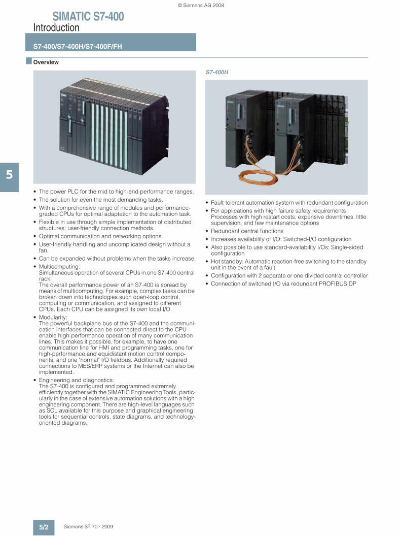
• The power PLC for the mid to high-end performance ranges.• The solution for even the most demanding tasks.• With a comprehensive range of modules and performance-
graded CPUs for optimal adaptation to the automation task.• Flexible in use through simple implementation of distributed
structures; user-friendly connection methods.• Optimal communication and networking options.• User-friendly handling and uncomplicated design without a
fan.• Can be expanded without problems when the tasks increase.• Multicomputing:
Simultaneous operation of several CPUs in one S7-400 central rack.The overall performance power of an S7-400 is spread by means of multicomputing. For example, complex tasks can be broken down into technologies such open-loop control, computing or communication, and assigned to different CPUs. Each CPU can be assigned its own local I/O.
• Modularity: The powerful backplane bus of the S7-400 and the communi-cation interfaces that can be connected direct to the CPU enable high-performance operation of many communication lines. This makes it possible, for example, to have one communication line for HMI and programming tasks, one for high-performance and equidistant motion control compo-nents, and one "normal" I/O fieldbus. Additionally required connections to MES/ERP systems or the Internet can also be implemented.
• Engineering and diagnostics: The S7-400 is configured and programmed extremely efficiently together with the SIMATIC Engineering Tools, partic-ularly in the case of extensive automation solutions with a high engineering component. There are high-level languages such as SCL available for this purpose and graphical engineering tools for sequential controls, state diagrams, and technology-oriented diagrams.
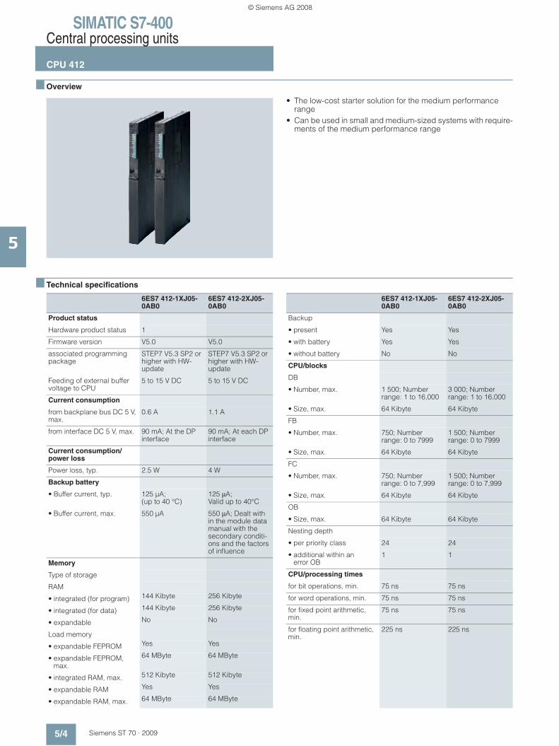
S7-400H
• Fault-tolerant automation system with redundant configuration• For applications with high failure safety requirements
Processes with high restart costs, expensive downtimes, little supervision, and few maintenance options
• Redundant central functions• Increases availability of I/O: Switched-I/O configuration• Also possible to use standard-availability I/Os: Single-sided
configuration• Hot standby: Automatic reaction-free switching to the standby
unit in the event of a fault• Configuration with 2 separate or one divided central controller• Connection of switched I/O via redundant PROFIBUS DP
© Siemens AG 2008

SIMATIC S7-400Introduction
S7-400/S7-400H/S7-400F/FH
5/3Siemens ST 70 · 2009
5
■ Overview (continued)
S7-400F/FH
• Failsafe automation system for plant with high safety require-ments
• Complies with safety requirements up to SIL 3 to IEC 61508, AK6 to DIN V 19250 and Cat. 4 to EN 954-1
• If required, also fault tolerant through redundant configuration• Without additional wiring of the failsafe I/O:
Failsafe communication via PROFIBUS DP with PROFISafe profile.
• Based on S7-400H and ET 200M, includes failsafe modules• Standard modules for non-safety-related applications can
also be used in the automation system• Isolating module for common use of failsafe and standard
modules in safety operation on an ET 200M
■ Technical specifications
For brochures serving as selection guides for SIMATIC products refer to:
http://www.siemens.com/simatic/printmaterial
General technical specifications
Degree of protection IP20
Ambient temperature 0 … +60 °C
Relative humidity 5 … 95 %, no condensation
Atmospheric pressure 860 … 1080 hPa
Electromagnetic compatibility EU Directive 89/336/EWG;
• per EN 50082-2 (noise immunity), testing per : IEC 61000-4-2, IEC 61000-4-4, IEC 61000-4-3, IEC 61000-4-6, IEC 61000-4-5;
Emitted interference to EN 50081-2, limit values according to EN 55011, Class A, Group 1
Mechanical tolerance
• Vibration, tested per/with IEC 68, Part 2-6/10 to 58 Hz; constant amplitude 0.075 mm;
58 to 150 Hz;constant acceleration 1 g;
Duration of vibrations: 10 frequency cycles per axis in the direction of each of the three mutually normal axes
• Impact, tested per/with IEC 68, Part 2-27/semi-sinusoidal:
impact 15 g (peak value), duration 11 ms
© Siemens AG 2008
SIMATIC S7-400Central processing units
CPU 412
5/4 Siemens ST 70 · 2009
5
■ Overview
• The low-cost starter solution for the medium performance range
• Can be used in small and medium-sized systems with require-ments of the medium performance range
■ Technical specifications
6ES7 412-1XJ05-0AB0
6ES7 412-2XJ05-0AB0
Product status
Hardware product status 1
Firmware version V5.0 V5.0
associated programming package
STEP7 V5.3 SP2 or higher with HW-update
STEP7 V5.3 SP2 or higher with HW-update
Feeding of external buffer voltage to CPU
5 to 15 V DC 5 to 15 V DC
Current consumption
from backplane bus DC 5 V, max.
0.6 A 1.1 A
from interface DC 5 V, max. 90 mA; At the DP interface
90 mA; At each DP interface
Current consumption/power loss
Power loss, typ. 2.5 W 4 W
Backup battery
• Buffer current, typ. 125 μA; (up to 40 °C)
125 μA; Valid up to 40°C
• Buffer current, max. 550 μA 550 μA; Dealt with in the module data manual with the secondary conditi-ons and the factors of influence
Memory
Type of storage
RAM
• integrated (for program) 144 Kibyte 256 Kibyte
• integrated (for data) 144 Kibyte 256 Kibyte
• expandable No No
Load memory
• expandable FEPROM Yes Yes
• expandable FEPROM, max.
64 MByte 64 MByte
• integrated RAM, max. 512 Kibyte 512 Kibyte
• expandable RAM Yes Yes
• expandable RAM, max. 64 MByte 64 MByte
6ES7 412-1XJ05-0AB0
6ES7 412-2XJ05-0AB0
Backup
• present Yes Yes
• with battery Yes Yes
• without battery No No
CPU/blocks
DB
• Number, max. 1 500; Number range: 1 to 16,000
3 000; Number range: 1 to 16,000
• Size, max. 64 Kibyte 64 Kibyte
FB
• Number, max. 750; Number range: 0 to 7999
1 500; Number range: 0 to 7999
• Size, max. 64 Kibyte 64 Kibyte
FC
• Number, max. 750; Number range: 0 to 7,999
1 500; Number range: 0 to 7,999
• Size, max. 64 Kibyte 64 Kibyte
OB
• Size, max. 64 Kibyte 64 Kibyte
Nesting depth
• per priority class 24 24
• additional within an error OB
1 1
CPU/processing times
for bit operations, min. 75 ns 75 ns
for word operations, min. 75 ns 75 ns
for fixed point arithmetic, min.
75 ns 75 ns
for floating point arithmetic, min.
225 ns 225 ns
© Siemens AG 2008

SIMATIC S7-400Central processing units
CPU 412
5/5Siemens ST 70 · 2009
5
■ Technical specifications (continued)
6ES7 412-1XJ05-0AB0
6ES7 412-2XJ05-0AB0
Times/counters and their remanence
S7 counter
• Number 2 048 2 048
• Remanence- adjustable Yes Yes- lower limit 0 0- upper limit 2 047 2 047- preset Z 0 to Z 7 Z 0 to Z 7
• Counting range- lower limit 0 0- upper limit 999 999
IEC counter
• present Yes Yes
• Type SFB SFB
S7 times
• Number 2 048 2 048
• Remanence- adjustable Yes Yes- lower limit 0 0- upper limit 2 047 2 047- preset No times retentive
• Time range- lower limit 10 ms 10 ms- upper limit 9 990 s 9 990 s
IEC timer
• present Yes Yes
• Type SFB SFB
Data areas and their remanence
remanent data area, total Total working and load memory
Total working and load memory (with backup battery)
Flag
• Number, max. 4 Kibyte 4 Kibyte
• Remanence available Yes Yes
• Number of clock memories 8; (in 1 memory byte)
8; (in 1 memory byte)
Address area
I/O address area
• Inputs 4 Kibyte 4 Kibyte
• Outputs 4 Kibyte 4 Kibyte
• of which, distributed- MPI/DP interface, inputs 2 Kibyte 2 Kibyte- MPI/DP interface,
outputs2 Kibyte 2 Kibyte
- DP interface, inputs 4 Kibyte- DP interface, outputs 4 Kibyte
6ES7 412-1XJ05-0AB0
6ES7 412-2XJ05-0AB0
Process image
• Inputs, adjustable 4 Kibyte 4 Kibyte
• Outputs, adjustable 4 Kibyte 4 Kibyte
• Inputs, preset 128 byte 128 byte
• Outputs, preset 128 byte 128 byte
• consistent data, max. 244 byte 244 byte
• Access to consistent data in process image
Yes Yes
Subprocess images
• Number of subprocess images, max.
15 15
Digital channels
• Inputs 32 768 32 768
• Outputs 32 768 32 768
• Inputs, of which central 32 768 32 768
• Outputs, of which central 32 768 32 768
Analog channels
• Inputs 2 048 2 048
• Outputs 2 048 2 048
• Inputs, of which central 2 048 2 048
• Outputs, of which central 2 048 2 048
Hardware config.
connectable OPs 31 31
Central devices, max. 1 1
Expansion devices, max. 21 21
Multicomputing Yes; Max. 4 CPUs (with UR1 or UR2)
Yes; Max. 4 CPUs (with UR1 or UR2)
IM
• Number of connectable IMs (total), max.
6 6
• Number of connectable IM 460s, max.
6 6
• Number of connectable IM 463s, max.
4; IM 463-2 4; IM 463-2
Number of DP masters
• integrated 1 2
• via IM 467 4 4
• via CP 10; CP 443-5 Extended
10; CP 443-5 Extended
• Mixed mode IM + CP permitted
No; IM 467 cannot be used with CP 443-5 Ext.; IM 467 cannot be used with CP 443-1 EX40 in PN IO mode
No; IM 467 cannot be used with CP 443-5 Ext.; IM 467 cannot be used with CP 443-1 EX40 in PN IO mode
• via interface module 0 0
• Number of pluggable S5 modules (via adapter capsule in central device), max.
6 6
© Siemens AG 2008

SIMATIC S7-400Central processing units
CPU 412
5/6 Siemens ST 70 · 2009
5
■ Technical specifications (continued)
6ES7 412-1XJ05-0AB0
6ES7 412-2XJ05-0AB0
Number of IO controllers
• integrated 0
• via CP 4; Via CP 443-1 EX 41 in PN mode; max. 4 in central controller
Via CP 443-1 EX 41 in PN mode; max. 4 in central controller
Number of operable FMs and CPs (recommended)
• FM Limited due to number of slots and number of connec-tions
Limited due to number of slots and number of connec-tions
• CP, point-to-point Limited due to number of slots and number of connec-tions
Limited due to number of slots and number of connec-tions
• PROFIBUS and Ethernet CPs
14; Of which 10 CPs max. or IMs as DP master, 4 PN controller maximum
14; Of which 10 CP or IM max. as DP master and PN controller
Time
Clock
• Hardware clock (real-time clock)
Yes Yes
• buffered and synchroni-zable
Yes Yes
• Resolution 1 ms 1 ms
Operating hours counter
• Number 8 8
Clock synchronization
• supports Yes Yes
• to MPI, Master Yes Yes
• to MPI, Slave Yes Yes
• to DP, Master Yes Yes
• to DP, Slave Yes Yes
• in AS, Master Yes Yes
• in AS, Slave Yes Yes
• on Ethernet via NTP No; Via CP No; Via CP
S7 message functions
Number of login stations for message functions, max.
31; Max. 31 with alarm_S and alarm_D (OP’s); max. 8 with alarm_8
31; Max. 31 with alarm_S and alarm_D (OP’s); max. 8 with alarm_8 and alarm_P (e.g. WinCC)
Symbol-related messages Yes Yes
Number of messages
• overall, max. 512 512
Block related messages Yes Yes
Alarm 8-blocks Yes Yes
Instrumentation & control messages
Yes Yes
6ES7 412-1XJ05-0AB0
6ES7 412-2XJ05-0AB0
Test commissioning functions
Status/control
• Status/control variable Yes Yes
Forcing
• Forcing Yes Yes
Status block Yes Yes
Single step Yes Yes
Number of breakpoints 4 4
Diagnostic buffer
• present Yes Yes
• Number of entries, max. 200 400
• adjustable Yes Yes
• preset 120 120
Communication functions
PG/OP communication Yes Yes
Routing Yes Yes
Global data communication
• supported Yes Yes
• Size of GD packets, max. 54 byte 54 byte
S7 basic communication
• supported Yes Yes
• Useful data per job, max. 76 byte 76 byte
S7 communication
• supported Yes Yes
• Useful data per job, max. 64 Kibyte 64 Kibyte
S5-compatible communi-cation
• supported Yes; Via FC AG_SEND and AG_RECV, max. via 10 CP 443-1 or 443-5
Yes; (via CP max. 10 and FC AG_SEND and FC AG_RECV)
• Useful data per job, max. 8 Kibyte 8 Kibyte
Standard communication (FMS)
• supported Yes; Via CP and loadable FB
Yes; Via CP and loadable FB
Web server
• Web server No; Via CP No; Via CP
• ISO-on-TCP (RFC1006) Via CP 443-1 Adv. and loadable FB
Via CP 443-1 Adv. and loadable FB
- Number of connections, max.
30
- Data length, max. 1 452 byte 1452
Number of connections
• overall 32 32
© Siemens AG 2008

SIMATIC S7-400Central processing units
CPU 412
5/7Siemens ST 70 · 2009
5
■ Technical specifications (continued)
6ES7 412-1XJ05-0AB0
6ES7 412-2XJ05-0AB0
1st interface
Physics RS 485 / PROFIBUS RS 485 / PROFIBUS
isolated Yes Yes
Functionality
• MPI Yes Yes
• DP master Yes Yes
• DP slave Yes Yes
MPI
• Number of connections 32 32
• Services- PG/OP communication Yes Yes- Routing Yes Yes- Global data communi-
cationYes Yes
- S7 basic communication Yes Yes- S7 communication Yes Yes
• Transmission speeds, max.
12 MBit/s 12 MBit/s
DP master
• Number of connections, max.
16 16
• Services- PG/OP communication Yes Yes- Routing Yes Yes- S7 basic communication Yes Yes- S7 communication Yes Yes- equidistance support Yes Yes- Activation/deactivation of
DP slavesYes Yes
- direct data exchange (cross traffic)
Yes Yes
• Transmission speeds, max.
12 MBit/s 12 MBit/s
• Number of DP slaves, max. 32; Max. 544 slots 32
• Address area- Inputs, max. 2 Kibyte 2 Kibyte- Outputs, max. 2 Kibyte 2 Kibyte
• Useful data per DP slave- Inputs, max. 244 byte 244 byte- Outputs, max. 244 byte 244 byte
DP slave
• Number of connections 16 16
• Services- PG/OP communication Yes Yes- Routing Yes Yes
• Transmission speeds, max.
12 MBit/s 12 MBit/s
• Transfer memory- Inputs 244 byte 244 byte- Outputs 244 byte 244 byte
• Address area, max. 32; Virtual slots 32
• Useful data per address area, max.
32 byte 32 byte
• Useful data per address area, of which consistent, max.
32 byte 32 byte
6ES7 412-1XJ05-0AB0
6ES7 412-2XJ05-0AB0
2nd interface
Physics RS 485 / PROFIBUS
isolated Yes
Functionality
• DP master Yes
• DP slave Yes
DP master
• Number of connections, max.
16
• Services- PG/OP communication Yes- Routing Yes- S7 basic communication Yes- S7 communication Yes- equidistance support Yes- Activation/deactivation of
DP slavesYes
- direct data exchange (cross traffic)
Yes
• Transmission speeds, max.
12 MBit/s
• Number of DP slaves, max. 64
• Address area- Inputs, max. 4 Kibyte- Outputs, max. 4 Kibyte
• Useful data per DP slave- Inputs, max. 244 byte- Outputs, max. 244 byte
DP slave
• Number of connections 16
• Services- Routing Yes- Programming Yes
• GSD file http://support.automation.siemens.com/WW/view/en/113652
• Transmission speeds, max.
12 MBit/s
• Transfer memory- Inputs 244 byte- Outputs 244 byte
• Address area, max. 32
• Useful data per address area, max.
32 byte
• Useful data per address area, of which consistent, max.
32 byte
Isochronous mode
Useful data per isoch-ronous slave, max.
244 byte 244 byte
equidistance Yes Yes
shortest clock pulse 1.5 ms; 0.5 ms without use of SFC 126, 127
1.5 ms; 0.5 ms without use of SFC 126, 127
© Siemens AG 2008

SIMATIC S7-400Central processing units
CPU 412
5/8 Siemens ST 70 · 2009
5
■ Technical specifications (continued)
6ES7 412-1XJ05-0AB0
6ES7 412-2XJ05-0AB0
CiR configuration in RUN
CiR synchronization time, basic load
100 ms 100 ms
CiR synchronization time, time per I/O slave
200 μs 200 μs
CPU/programming
Configuration software
• STEP 7 Yes Yes
Programming language
• LAD Yes Yes
• FUP Yes Yes
• AWL Yes Yes
• SCL Yes Yes
• CFC Yes Yes
• GRAPH Yes Yes
• HiGraph Yes Yes
6ES7 412-1XJ05-0AB0
6ES7 412-2XJ05-0AB0
Nesting levels 7 7
User program protection/password protection
Yes Yes
Dimensions
Required slots 1 1
Dimensions
• Width 25 mm 25 mm
• Height 290 mm 290 mm
• Depth 219 mm 219 mm
Weights
• Weight, approx. 720 g 720 g
© Siemens AG 2008
SIMATIC S7-400Central processing units
CPU 412
5/9Siemens ST 70 · 2009
5
■ Ordering data Order No. Order No.
B3: Subject to export regulations: AL: N and ECCN: 5D992B1
CPU 412-1 6ES7 412-1XJ05-0AB0
Main memory 288 KB, power supply 24 V DC, MPI/PROFIBUS DP master interface, slot for memory card, incl. slot number labels
CPU 412-2 6ES7 412-2XJ05-0AB0
Main memory 512 KB, power supply 24 V DC, MPI/PROFIBUS DP master interface, slot for memory card, incl. slot number labels
Memory card RAM
64 KB 6ES7 952-0AF00-0AA0
256 KB 6ES7 952-1AH00-0AA0
1 MB 6ES7 952-1AK00-0AA0
2 MB 6ES7 952-1AL00-0AA0
4 MB 6ES7 952-1AM00-0AA0
8 MB 6ES7 952-1AP00-0AA0
16 MB 6ES7 952-1AS00-0AA0
64 MB 6ES7 952-1AY00-0AA0
FEPROM memory card
64 KB 6ES7 952-0KF00-0AA0
256 KB 6ES7 952-0KH00-0AA0
1 MB 6ES7 952-1KK00-0AA0
2 MB 6ES7 952-1KL00-0AA0
4 MB 6ES7 952-1KM00-0AA0
8 MB 6ES7 952-1KP00-0AA0
16 MB 6ES7 952-1KS00-0AA0
32 MB 6ES7 952-1KT00-0AA0
64 MB 6ES7 952-1KY00-0AA0
MPI cable 6ES7 901-0BF00-0AA0
For connecting SIMATIC S7 and the PG through MPI; 5 m in length
Slot number plates 6ES7 912-0AA00-0AA0
1 set (spare part)
Manual "SIMATIC S7-400 automation system"
incl. instruction list
German 6ES7 498-8AA05-8AA0
English 6ES7 498-8AA05-8BA0
French 6ES7 498-8AA05-8CA0
Spanish 6ES7 498-8AA05-8DA0
Italian 6ES7 498-8AA05-8EA0
S7-400 instructions list
German 6ES7 498-8AA05-8AN0
English 6ES7 498-8AA05-8BN0
French 6ES7 498-8AA05-8CN0
Spanish 6ES7 498-8AA05-8DN0
Italian 6ES7 498-8AA05-8EN0
Manual "Communication for SIMATIC S7-300/-400"
German 6ES7 398-8EA00-8AA0
English 6ES7 398-8EA00-8BA0
French 6ES7 398-8EA00-8CA0
Spanish 6ES7 398-8EA00-8DA0
Italian 6ES7 398-8EA00-8EA0
SIMATIC Manual Collection B3 6ES7 998-8XC01-8YE0
Electronic manuals on DVD, five languages: S7-200/300/400, C7, LOGO!, SIMATIC DP, PC, PG, STEP 7, engineering software, runtime software, PCS 7, SIMATIC HMI, SIMATIC NET
SIMATIC Manual Collection update service for 1 year
B3 6ES7 998-8XC01-8YE2
Current "Manual Collection" DVD and the three subsequent updates
Brochure "SIMATIC S7-400 automation system - Design and application"
German 6ES7 498-8AA00-8AB0
English 6ES7 498-8AA00-8BB0
RS 485 bus connector with 90° cable outlet
Max. transfer rate 12 Mbit/s
Without PG interface 6ES7 972-0BA12-0XA0
With PG interface 6ES7 972-0BB12-0XA0
RS 485 bus connector with angled cable outlet
Max. transfer rate 12 Mbit/s
Without PG interface 6ES7 972-0BA41-0XA0
With PG interface 6ES7 972-0BB41-0XA0
RS 485 bus connector with 90° cable outlet for Fast Connect system
Max. transfer rate 12 Mbit/s
Without PG interface 6ES7 972-0BA51-0XA0
With PG interface 6ES7 972-0BB51-0XA0
RS 485 bus connector with axial cable outlet
For SIMATIC OP, for connection to PPI, MPI, PROFIBUS
6GK1 500-0EA02
PROFIBUS FastConnect bus cable
Standard type with special design for quick mounting, 2-core, shielded, sold by the meter, max. delivery unit 1000 m, minimum order quantity 20 m
6XV1 830-0EH10
© Siemens AG 2008

SIMATIC S7-400Central processing units
CPU 414
5/10 Siemens ST 70 · 2009
5
■ Overview
• CPUs for high demands in the mid-level performance range• Applicable for plants with additional demands on
programming scope and processing speed• Integrated PROFINET functions in CPU 414-3 PN/DP
■ Technical specifications
6ES7 414-2XK05-0AB0 6ES7 414-3XM05-0AB0 6ES7 414-3EM05-0AB0
Product status
Hardware product status 1
Firmware version V5.0 V5.0 V5.0
associated programming package
STEP7 V5.3 SP2 or higher with HW-update
STEP7 V5.3 SP2 or higher with HW-update
STEP7 V5.4 SP1 or higher
Feeding of external buffer voltage to CPU
5 to 15 VDC 5 to 15 VDC 5 to 15 VDC
Current consumption
from backplane bus DC 5 V, max.
1.1 A 1.3 A 1.4 A
from interface DC 5 V, max. 90 mA; At each DP interface 90 mA; At each DP interface 90 mA; At each DP interface
Current consumption/power loss
Power loss, typ. 4 W 4.5 W 5.5 W
Backup battery
• Buffer current, typ. 125 μA; Valid up to 40°C 125 μA; Valid up to 40°C 125 μA; Valid up to 40°C
• Buffer current, max. 550 μA 550 μA 550 μA
Memory
Type of storage
RAM
• integrated (for program) 0.5 MByte 1.4 MByte 1.4 MByte
• integrated (for data) 0.5 MByte 1.4 MByte 1.4 MByte
• expandable No No No
Load memory
• expandable FEPROM Yes Yes Yes
• expandable FEPROM, max. 64 MByte 64 MByte 64 MByte
• integrated RAM, max. 512 Kibyte 512 Kibyte 512 Kibyte
• expandable RAM Yes Yes Yes
• expandable RAM, max. 64 MByte 64 MByte 64 MByte
Backup
• present Yes Yes Yes
• with battery Yes Yes Yes; All data
• without battery No No No
CPU/blocks
DB
• Number, max. 6 000; Number range: 1 to 16,000 6 000; Number range: 1 to 16,000 6 000; Number range: 1 to 16,000
• Size, max. 64 Kibyte 64 Kibyte 64 Kibyte
© Siemens AG 2008
SIMATIC S7-400Central processing units
CPU 414
5/11Siemens ST 70 · 2009
5
■ Technical specifications (continued)
6ES7 414-2XK05-0AB0 6ES7 414-3XM05-0AB0 6ES7 414-3EM05-0AB0
FB
• Number, max. 3 000; Number range: 0 to 7999 3 000; Number range: 0 to 7999 3 000; Number range: 0 to 7999
• Size, max. 64 Kibyte 64 Kibyte 64 Kibyte
FC
• Number, max. 3 000; Number range: 0 to 7,999 3 000; Number range: 0 to 7999 3 000; Number range: 0 to 7999
• Size, max. 64 Kibyte 64 Kibyte 64 Kibyte
OB
• Size, max. 64 Kibyte 64 Kibyte 64 Kibyte
Nesting depth
• per priority class 24 24 24
• additional within an error OB 1 1 1
CPU/processing times
for bit operations, min. 45 ns 45 ns 45 ns
for word operations, min. 45 ns 45 ns 45 ns
for fixed point arithmetic, min. 45 ns 45 ns 45 ns
for floating point arithmetic, min. 135 ns 135 ns 135 ns
Times/counters and their remanence
S7 counter
• Number 2 048 2 048 2 048
• Remanence- adjustable Yes Yes Yes- lower limit 0 0 0- upper limit 2 047 2 047 2 047- preset From Z 0 to Z 7 From Z 0 to Z 7 From Z 0 to Z 7
• Counting range- lower limit 0 0 0- upper limit 999 999 999
IEC counter
• present Yes Yes Yes
• Type SFB SFB SFB
S7 times
• Number 2 048 2 048 2 048
• Remanence- adjustable Yes Yes Yes- lower limit 0 0 0- upper limit 2 047 2 047 2 047- preset No times retentive No times retentive
• Time range- lower limit 10 ms 10 ms 10 ms- upper limit 9 990 s 9 990 s 9 990 s
IEC timer
• present Yes Yes Yes
• Type SFB SFB SFB
Data areas and their remanence
remanent data area, total Total working and load memory (with backup battery)
Total working and load memory(with backup battery)
Total working and load memory (with backup battery)
© Siemens AG 2008

SIMATIC S7-400Central processing units
CPU 414
5/12 Siemens ST 70 · 2009
5
■ Technical specifications (continued)
6ES7 414-2XK05-0AB0 6ES7 414-3XM05-0AB0 6ES7 414-3EM05-0AB0
Flag
• Number, max. 8 Kibyte 8 Kibyte 8 Kibyte
• Remanence available Yes Yes Yes
• Number of clock memories 8; (in 1 memory byte) 8; (in 1 memory byte) 8; (in 1 memory byte)
Address area
I/O address area
• Inputs 8 Kibyte 8 Kibyte 8 Kibyte
• Outputs 8 Kibyte 8 Kibyte 8 Kibyte
• of which, distributed- MPI/DPinterface, inputs 2 Kibyte 2 Kibyte 2 Kibyte- MPI/DP interface, outputs 2 Kibyte 2 Kibyte 2 Kibyte- DP interface, inputs 6 Kibyte 6 Kibyte 6 Kibyte- DP interface, outputs 6 Kibyte 6 Kibyte 6 Kibyte- PN interface, inputs 8 Kibyte- PN interface, outputs 8 Kibyte
Process image
• Inputs, adjustable 8 Kibyte 8 Kibyte 8 Kibyte
• Outputs, adjustable 8 Kibyte 8 Kibyte 8 Kibyte
• Inputs, preset 256 byte 256 byte 256 byte
• Outputs, preset 256 byte 256 byte 256 byte
• consistent data, max. 244 byte 244 byte 244 byte
• Access to consistent data in process image
Yes Yes Yes
Subprocess images
• Number of subprocess images, max.
15 15 15
Digital channels
• Inputs 65 536 65 536 65 536
• Outputs 65 536 65 536 65 536
• Inputs, of which central 65 536 65 536 65 536
• Outputs, of which central 65 536 65 536 65 536
Analog channels
• Inputs 4 096 4 096 4 096
• Outputs 4 096 4 096 4 096
• Inputs, of which central 4 096 4 096 4 096
• Outputs, of which central 4 096 4 096 4 096
Hardware config.
connectable OPs 31 31 31
Central devices, max. 1 1 1
Expansion devices, max. 21 21 21
Multicomputing Yes; Max. 4 CPUs (with UR1 or UR2) Yes; Max. 4 CPUs (with UR1 or UR2) Yes; Max. 4 CPUs (with UR1 or UR2)
IM
• Number of connectable IMs (total), max.
6 6 6
• Number of connectable IM 460s, max.
6 6 6
• Number of connectable IM 463s, max.
4; IM 463-2 4; IM 463-2 4; IM 463-2
© Siemens AG 2008

SIMATIC S7-400Central processing units
CPU 414
5/13Siemens ST 70 · 2009
5
■ Technical specifications (continued)
6ES7 414-2XK05-0AB0 6ES7 414-3XM05-0AB0 6ES7 414-3EM05-0AB0
Number of DP masters
• integrated 2 2 1
• via IM 467 4 4 4
• via CP 10; CP 443-5 Extended 10; CP 443-5 Extended 10; CP 443-5 Extended
• Mixed mode IM + CP permitted No; IM 467 cannot be used with CP 443-5 Ext.; IM 467 cannot be used with CP 443-1 EX40 in PN IO mode
No; IM 467 cannot be used with CP 443-5 Ext.; IM 467 cannot be used with CP 443-1 EX40 in PN IO mode
No; IM 467 cannot be used with CP 443-5 Ext.; IM 467 cannot be used with CP 443-1 EX40 in PN IO mode
• via interface module 0 1 1; IF 964-DP
• Number of pluggable S5 modules (via adapter capsule in central device), max.
6 6 6
Number of IO controllers
• integrated 1
• via CP 4; Via CP 443-1 EX 41 in PN mode; max. 4 in central controller
4; Via CP 443-1 EX 41 in PN mode; max. 4 in central controller
4; Via CP 443-1 EX 41 in PN mode; max. 4 in central controller
Number of operable FMs and CPs (recommended)
• FM Limited due to number of slots and number of connections
Limited due to number of slots and number of connections
Limited due to number of slots and number of connections
• CP, point-to-point Limited due to number of slots and number of connections
Limited due to number of slots and number of connections
Limited due to number of slots and number of connections
• PROFIBUS and Ethernet CPs 14; Of which 10 CP or IM max. as DP master and PN controller
14; Of which 10 CP or IM max. as DP master and PN controller
14; Of which 10 CP/IM max. as DP master and PN controller
Time
Clock
• Hardware clock (real-time clock)
Yes Yes Yes
• buffered and synchronizable Yes Yes Yes
• Resolution 1 ms 1 ms 1 ms
Operating hours counter
• Number 8 8 8
Clock synchronization
• supports Yes Yes Yes
• to MPI, Master Yes Yes Yes
• to MPI, Slave Yes Yes Yes
• to DP, Master Yes Yes Yes
• to DP, Slave Yes Yes Yes
• in AS, Master Yes Yes Yes
• in AS, Slave Yes Yes Yes
• on Ethernet via NTP Yes; as client
• to IF 964 DP Yes Yes
S7 message functions
Number of login stations for message functions, max.
31; Max. 31 with alarm_S and alarm_D (OP’s); max. 8 with alarm_8 and alarm_P (e.g. WinCC)
31; Max. 31 with alarm_S and alarm_D (OP’s); max. 8 with alarm_8 and alarm_P (e.g. WinCC)
31; Max. 31 with alarm_S and alarm_D (OP’s); max. 8 with alarm_8 and alarm_P (e.g. WinCC)
Symbol-related messages Yes Yes Yes
Number of messages
• overall, max. 512 512 512
Block related messages Yes Yes Yes
Alarm 8-blocks Yes Yes Yes
Instrumentation & control messages
Yes Yes Yes
© Siemens AG 2008
SIMATIC S7-400Central processing units
CPU 414
5/14 Siemens ST 70 · 2009
5
■ Technical specifications (continued)
6ES7 414-2XK05-0AB0 6ES7 414-3XM05-0AB0 6ES7 414-3EM05-0AB0
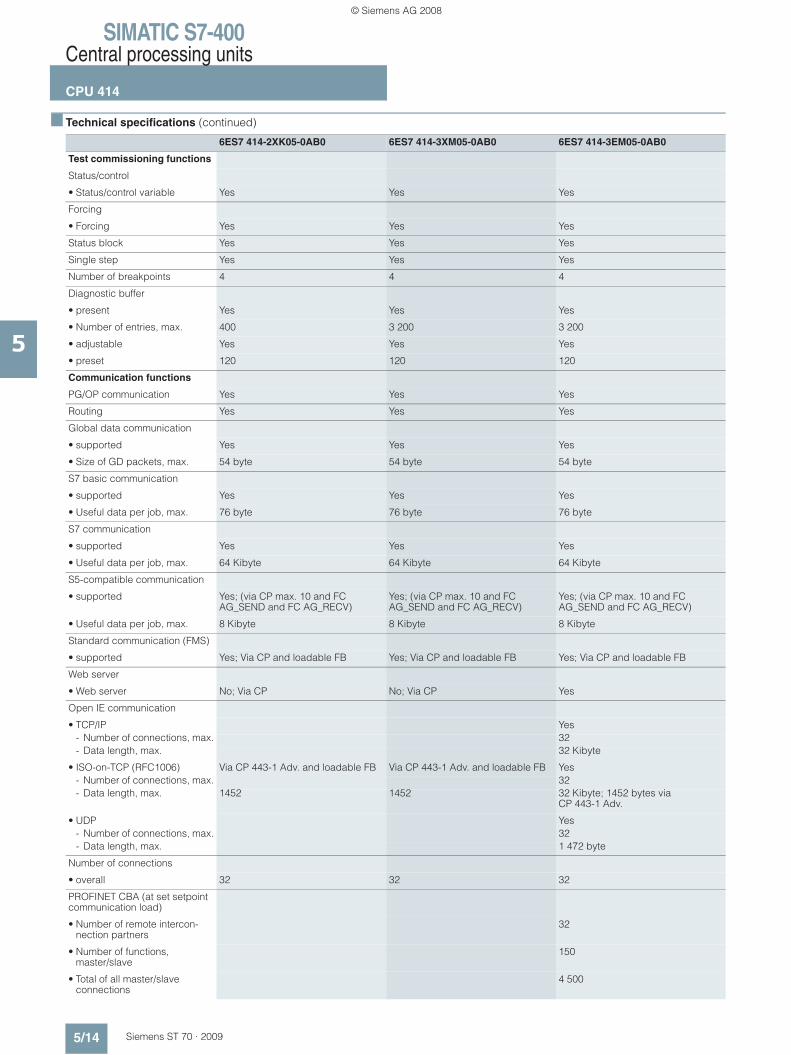
Test commissioning functions
Status/control
• Status/control variable Yes Yes Yes
Forcing
• Forcing Yes Yes Yes
Status block Yes Yes Yes
Single step Yes Yes Yes
Number of breakpoints 4 4 4
Diagnostic buffer
• present Yes Yes Yes
• Number of entries, max. 400 3 200 3 200
• adjustable Yes Yes Yes
• preset 120 120 120
Communication functions
PG/OP communication Yes Yes Yes
Routing Yes Yes Yes
Global data communication
• supported Yes Yes Yes
• Size of GD packets, max. 54 byte 54 byte 54 byte
S7 basic communication
• supported Yes Yes Yes
• Useful data per job, max. 76 byte 76 byte 76 byte
S7 communication
• supported Yes Yes Yes
• Useful data per job, max. 64 Kibyte 64 Kibyte 64 Kibyte
S5-compatible communication
• supported Yes; (via CP max. 10 and FC AG_SEND and FC AG_RECV)
Yes; (via CP max. 10 and FC AG_SEND and FC AG_RECV)
Yes; (via CP max. 10 and FC AG_SEND and FC AG_RECV)
• Useful data per job, max. 8 Kibyte 8 Kibyte 8 Kibyte
Standard communication (FMS)
• supported Yes; Via CP and loadable FB Yes; Via CP and loadable FB Yes; Via CP and loadable FB
Web server
• Web server No; Via CP No; Via CP Yes
Open IE communication
• TCP/IP Yes- Number of connections, max. 32- Data length, max. 32 Kibyte
• ISO-on-TCP (RFC1006) Via CP 443-1 Adv. and loadable FB Via CP 443-1 Adv. and loadable FB Yes- Number of connections, max. 32- Data length, max. 1452 1452 32 Kibyte; 1452 bytes via
CP 443-1 Adv.
• UDP Yes- Number of connections, max. 32- Data length, max. 1 472 byte
Number of connections
• overall 32 32 32
PROFINET CBA (at set setpoint communication load)
• Number of remote intercon-nection partners
32
• Number of functions, master/slave
150
• Total of all master/slave connections
4 500
© Siemens AG 2008
SIMATIC S7-400Central processing units
CPU 414
5/15Siemens ST 70 · 2009
5
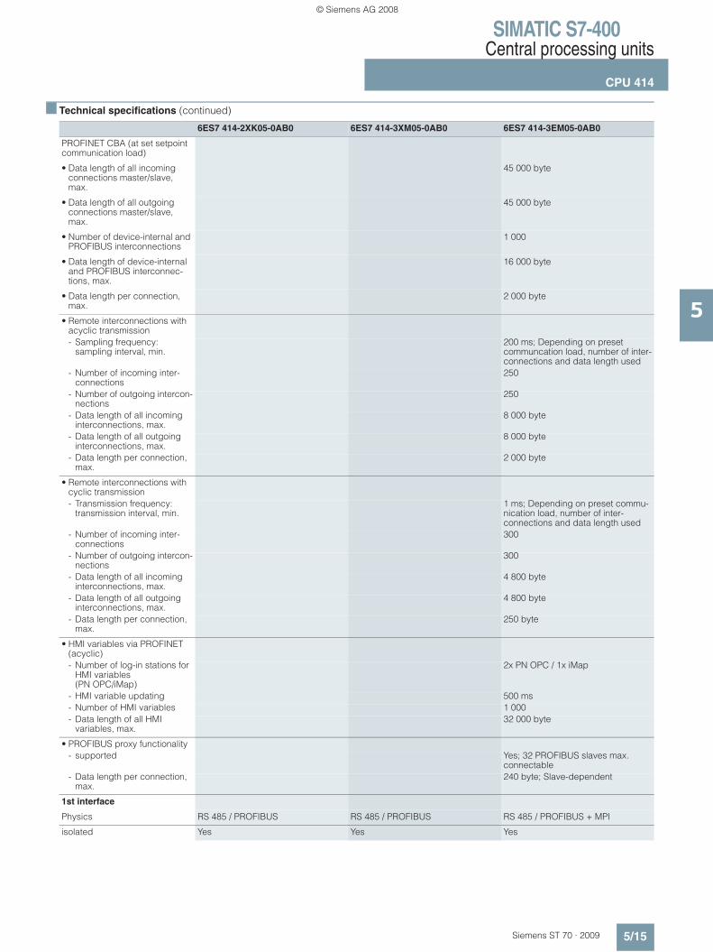
■ Technical specifications (continued)
6ES7 414-2XK05-0AB0 6ES7 414-3XM05-0AB0 6ES7 414-3EM05-0AB0
PROFINET CBA (at set setpoint communication load)
• Data length of all incoming connections master/slave, max.
45 000 byte
• Data length of all outgoing connections master/slave, max.
45 000 byte
• Number of device-internal and PROFIBUS interconnections
1 000
• Data length of device-internal and PROFIBUS interconnec-tions, max.
16 000 byte
• Data length per connection, max.
2 000 byte
• Remote interconnections with acyclic transmission- Sampling frequency:
sampling interval, min.200 ms; Depending on preset communcation load, number of inter-connections and data length used
- Number of incoming inter-connections
250
- Number of outgoing intercon-nections
250
- Data length of all incoming interconnections, max.
8 000 byte
- Data length of all outgoing interconnections, max.
8 000 byte
- Data length per connection, max.
2 000 byte
• Remote interconnections with cyclic transmission- Transmission frequency:
transmission interval, min.1 ms; Depending on preset commu-nication load, number of inter-connections and data length used
- Number of incoming inter-connections
300
- Number of outgoing intercon-nections
300
- Data length of all incoming interconnections, max.
4 800 byte
- Data length of all outgoing interconnections, max.
4 800 byte
- Data length per connection, max.
250 byte
• HMI variables via PROFINET (acyclic)- Number of log-in stations for
HMI variables (PN OPC/iMap)
2x PN OPC / 1x iMap
- HMI variable updating 500 ms- Number of HMI variables 1 000- Data length of all HMI
variables, max.32 000 byte
• PROFIBUS proxy functionality- supported Yes; 32 PROFIBUS slaves max.
connectable- Data length per connection,
max.240 byte; Slave-dependent
1st interface
Physics RS 485 / PROFIBUS RS 485 / PROFIBUS RS 485 / PROFIBUS + MPI
isolated Yes Yes Yes
© Siemens AG 2008
SIMATIC S7-400Central processing units
CPU 414
5/16 Siemens ST 70 · 2009
5
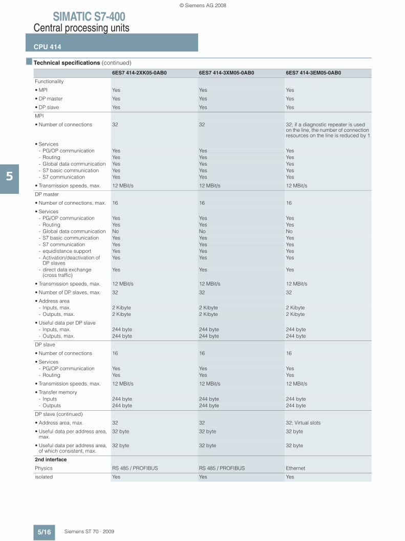
■ Technical specifications (continued)
6ES7 414-2XK05-0AB0 6ES7 414-3XM05-0AB0 6ES7 414-3EM05-0AB0
Functionality
• MPI Yes Yes Yes
• DP master Yes Yes Yes
• DP slave Yes Yes Yes
MPI
• Number of connections 32 32 32; if a diagnostic repeater is used on the line, the number of connection resources on the line is reduced by 1
• Services- PG/OP communication Yes Yes Yes- Routing Yes Yes Yes- Global data communication Yes Yes Yes- S7 basic communication Yes Yes Yes- S7 communication Yes Yes Yes
• Transmission speeds, max. 12 MBit/s 12 MBit/s 12 MBit/s
DP master
• Number of connections, max. 16 16 16
• Services- PG/OP communication Yes Yes Yes- Routing Yes Yes Yes- Global data communication No No No- S7 basic communication Yes Yes Yes- S7 communication Yes Yes Yes- equidistance support Yes Yes Yes- Activation/deactivation of
DP slavesYes Yes Yes
- direct data exchange (cross traffic)
Yes Yes Yes
• Transmission speeds, max. 12 MBit/s 12 MBit/s 12 MBit/s
• Number of DP slaves, max. 32 32 32
• Address area- Inputs, max. 2 Kibyte 2 Kibyte 2 Kibyte- Outputs, max. 2 Kibyte 2 Kibyte 2 Kibyte
• Useful data per DP slave- Inputs, max. 244 byte 244 byte 244 byte- Outputs, max. 244 byte 244 byte 244 byte
DP slave
• Number of connections 16 16 16
• Services- PG/OP communication Yes Yes Yes- Routing Yes Yes Yes
• Transmission speeds, max. 12 MBit/s 12 MBit/s 12 MBit/s
• Transfer memory- Inputs 244 byte 244 byte 244 byte- Outputs 244 byte 244 byte 244 byte
DP slave (continued)
• Address area, max. 32 32 32; Virtual slots
• Useful data per address area, max.
32 byte 32 byte 32 byte
• Useful data per address area, of which consistent, max.
32 byte 32 byte 32 byte
2nd interface
Physics RS 485 / PROFIBUS RS 485 / PROFIBUS Ethernet
isolated Yes Yes Yes
© Siemens AG 2008
SIMATIC S7-400Central processing units
CPU 414
5/17Siemens ST 70 · 2009
5
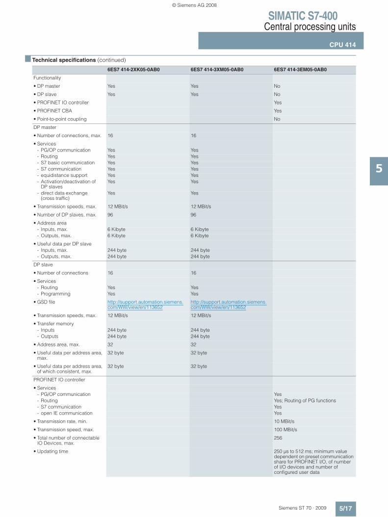
■ Technical specifications (continued)
6ES7 414-2XK05-0AB0 6ES7 414-3XM05-0AB0 6ES7 414-3EM05-0AB0
Functionality
• DP master Yes Yes No
• DP slave Yes Yes No
• PROFINET IO controller Yes
• PROFINET CBA Yes
• Point-to-point coupling No
DP master
• Number of connections, max. 16 16
• Services- PG/OP communication Yes Yes- Routing Yes Yes- S7 basic communication Yes Yes- S7 communication Yes Yes- equidistance support Yes Yes- Activation/deactivation of
DP slavesYes Yes
- direct data exchange (cross traffic)
Yes Yes
• Transmission speeds, max. 12 MBit/s 12 MBit/s
• Number of DP slaves, max. 96 96
• Address area- Inputs, max. 6 Kibyte 6 Kibyte- Outputs, max. 6 Kibyte 6 Kibyte
• Useful data per DP slave- Inputs, max. 244 byte 244 byte- Outputs, max. 244 byte 244 byte
DP slave
• Number of connections 16 16
• Services- Routing Yes Yes- Programming Yes Yes
• GSD file http://support.automation.siemens.com/WW/view/en/113652
http://support.automation.siemens.com/WW/view/en/113652
• Transmission speeds, max. 12 MBit/s 12 MBit/s
• Transfer memory- Inputs 244 byte 244 byte- Outputs 244 byte 244 byte
• Address area, max. 32 32
• Useful data per address area, max.
32 byte 32 byte
• Useful data per address area, of which consistent, max.
32 byte 32 byte
PROFINET IO controller
• Services- PG/OP communication Yes- Routing Yes; Routing of PG functions- S7 communication Yes- open IE communication Yes
• Transmission rate, min. 10 MBit/s
• Transmission speed, max. 100 MBit/s
• Total number of connectable IO Devices, max.
256
• Updating time 250 μs to 512 ms; minimum value dependent on preset communication share for PROFINET I/O, of number of I/O devices and number of configured user data
© Siemens AG 2008

SIMATIC S7-400Central processing units
CPU 414
5/18 Siemens ST 70 · 2009
5
■ Technical specifications (continued)
6ES7 414-2XK05-0AB0 6ES7 414-3XM05-0AB0 6ES7 414-3EM05-0AB0
PROFINET IO controller (cont.)
• Address area- Inputs, max. 8 Kibyte- Outputs, max. 8 Kibyte- Useful data consistency,
max.255 byte; incl. net data accompaniers
PROFINET CBA
• Acyclic transmission Yes
• cyclic transmission Yes
3rd interface
Type of interfaces Pluggable interface module (IF), technical specifications as for 2nd interface
Pluggable interface module (IF)
pluggable interface module IF 964-DP (Order No.: 6ES7 964-2AA04-0AB0)
IF 964-DP (Order No.: 6ES7 964-2AA04-0AB0)
Physics RS 485 / PROFIBUS
isolated Yes
power supply to interface (15 to 30 V DC), max.
150 mA; max. 150 mA
Number of connection resources 16
Functionality
• MPI No
• DP master Yes
• DP slave Yes
DP master
• Number of connections, max. 16
• Services- PG/OP communication Yes- Routing Yes- Global data communication No- S7 basic communication Yes- S7 communication Yes- Equidistance support Yes- SYNC/FREEZE Yes- Activation/deactivation of
DP slavesYes
- Direct data exchange Yes
• Transmission rate, max. 12 MBit/s
• Number of DP slaves, max. 96
• Address area- Inputs, max. 6 Kibyte- Outputs, max. 6 Kibyte
• Useful data per DP slave- Useful data per DP slave,
max.244 byte
- Inputs, max. 244 byte- Outputs, max. 244 byte- Slots, max. 244- per slot, max. 128 byte
DP slave
• Number of connections 16
• Services- Routing Yes- Status/control Yes
© Siemens AG 2008

SIMATIC S7-400Central processing units
CPU 414
5/19Siemens ST 70 · 2009
5
■ Technical specifications (continued)
6ES7 414-2XK05-0AB0 6ES7 414-3XM05-0AB0 6ES7 414-3EM05-0AB0
DP slave (continued)
• GSD file http://support.automation.siemens.com/WW/view/en/113652
• Transmission rate, max. 12 MBit/s
• Transfer memory- Inputs 244 byte- Outputs 244 byte
• Address range, max. 32
• Useful data per address area, max.
32 byte
• Useful data per address area, of which consistent, max.
32 byte
Isochronous mode
Useful data per isochronoous slave, max.
244 byte 244 byte 244 byte
equidistance Yes Yes Yes
shortest clock pulse 1 ms; 0.5 ms without use of SFC 126, 127
1 ms; 0.5 ms without use of SFC 126, 127
1 ms; Without use of SFC 126 and 127 up to 0.5 ms
CiR configuration in RUN
CiR synchronization time, basic load
100 ms 100 ms 100 ms
CiR synchronization time, time per I/O slave
80 μs 80 μs 80 μs
CPU/programming
Configuration software
• STEP 7 Yes Yes Yes
Programming language
• STEP 7 Yes
• LAD Yes Yes Yes
• FUP Yes Yes Yes
• AWL Yes Yes Yes
• SCL Yes Yes Yes
• CFC Yes Yes Yes
• GRAPH Yes Yes Yes
• HiGraph Yes Yes Yes
Nesting levels 7 7 7
User program protection/password protection
Yes Yes Yes
Dimensions
Required slots 1 2 2
Dimensions Dimensions
• Width 25 mm 50 mm 50 mm
• Height 290 mm 290 mm 290 mm
• Depth 219 mm 219 mm 219 mm
Weights
• Weight, approx. 720 g 880 g 900 g
© Siemens AG 2008

SIMATIC S7-400Central processing units
CPU 414
5/20 Siemens ST 70 · 2009
5
■ Ordering data Order No. Order No.
B3: Subject to export regulations: AL: N and ECCN: 5D992B1
CPU 414-2 6ES7 414-2XK05-0AB0
Main memory 1 MB, power supply 24 V DC, MPI/PROFIBUS DP master interface, slot for memory card, incl. slot number labels
CPU 414-3 6ES7 414-3XM05-0AB0
Main memory 2.8 MB, power supply 24 V DC, MPI/PROFIBUS DP master interface, PROFIBUS DP master interface, slot for memory card, module slots for 1 IF module,incl. slot number labels
CPU 414-3 PN/DP 6ES7 414-3EM05-0AB0
Main memory 2.8 MB, power supply 24 V DC, MPI/PROFIBUS DP master interface, PROFINET interface, slot for memory card, module slot for 1 IF module, incl. slot number labels
Memory card RAM
64 KB 6ES7 952-0AF00-0AA0
256 KB 6ES7 952-1AH00-0AA0
1 MB 6ES7 952-1AK00-0AA0
2 MB 6ES7 952-1AL00-0AA0
4 MB 6ES7 952-1AM00-0AA0
8 MB 6ES7 952-1AP00-0AA0
16 MB 6ES7 952-1AS00-0AA0
64 MB 6ES7 952-1AY00-0AA0
FEPROM memory card
64 KB 6ES7 952-0KF00-0AA0
256 KB 6ES7 952-0KH00-0AA0
1 MB 6ES7 952-1KK00-0AA0
2 MB 6ES7 952-1KL00-0AA0
4 MB 6ES7 952-1KM00-0AA0
8 MB 6ES7 952-1KP00-0AA0
16 MB 6ES7 952-1KS00-0AA0
32 MB 6ES7 952-1KT00-0AA0
64 MB 6ES7 952-1KY00-0AA0
MPI cable 6ES7 901-0BF00-0AA0
For connecting SIMATIC S7 and the PG through MPI; 5 m in length
IF 964-DP interface module 6ES7 964-2AA04-0AB0
For connecting an additional PROFIBUS subnet; for CPU 414-3, CPU 414-3 PN/DP, CPU 416-3, CPU 416-3 PN/DP, CPU 417-4
Slot number plates 6ES7 912-0AA00-0AA0
1 set (spare part)
Manual "SIMATIC S7-400 automation system"
incl. instruction list
German 6ES7 498-8AA05-8AA0
English 6ES7 498-8AA05-8BA0
French 6ES7 498-8AA05-8CA0
Spanish 6ES7 498-8AA05-8DA0
Italian 6ES7 498-8AA05-8EA0
S7-400 instructions list
German 6ES7 498-8AA05-8AN0
English 6ES7 498-8AA05-8BN0
French 6ES7 498-8AA05-8CN0
Spanish 6ES7 498-8AA05-8DN0
Italian 6ES7 498-8AA05-8EN0
Manual "Communication for SIMATIC S7-300/-400"
German 6ES7 398-8EA00-8AA0
English 6ES7 398-8EA00-8BA0
French 6ES7 398-8EA00-8CA0
Spanish 6ES7 398-8EA00-8DA0
Italian 6ES7 398-8EA00-8EA0
SIMATIC Manual Collection B3 6ES7 998-8XC01-8YE0
Electronic manuals on DVD, five languages: S7-200/300/400, C7, LOGO!, SIMATIC DP, PC, PG, STEP 7, engineering software, runtime software, PCS 7, SIMATIC HMI, SIMATIC NET
SIMATIC Manual Collection update service for 1 year
B3 6ES7 998-8XC01-8YE2
Current "Manual Collection" DVD and the three subsequent updates
Brochure "SIMATIC S7-400 automation system - Design and application"
German 6ES7 498-8AA00-8AB0
English 6ES7 498-8AA00-8BB0
© Siemens AG 2008
SIMATIC S7-400Central processing units
CPU 414
5/21Siemens ST 70 · 2009
5
■ Ordering data Order No. Order No.
PROFIBUS bus components
RS 485 bus connector with 90° cable outlet
Max. transfer rate 12 Mbit/s
Without PG interface 6ES7 972-0BA12-0XA0
With PG interface 6ES7 972-0BB12-0XA0
RS 485 bus connector with angled cable outlet
Max. transfer rate 12 Mbit/s
Without PG interface 6ES7 972-0BA41-0XA0
With PG interface 6ES7 972-0BB41-0XA0
RS 485 bus connector with 90° cable outlet for FastConnect system
Max. transfer rate 12 Mbit/s
Without PG interface 6ES7 972-0BA51-0XA0
With PG interface 6ES7 972-0BB51-0XA0
RS 485 bus connector with axial cable outlet
For SIMATIC OP, for connection to PPI, MPI, PROFIBUS
6GK1 500-0EA02
PROFIBUS FastConnect bus cable
Standard type with special design for quick mounting, 2-core, shielded, sold by the meter, max. delivery unit 1000 m, minimum order quantity 20 m
6XV1 830-0EH10
RS 485 repeater for PROFIBUS 6ES7 972-0AA01-0XA0
Data transfer rate up to 12 Mbit/s; 24 V DC; IP20 housing
PROFINET bus components
IE FC TP Standard Cable GP 2x2
6XV1 840-2AH10
4-core, shielded TP installation cable for connection to IE FC Outlet RJ45/ IE FC RJ45 Plug; PROFINET-compatible; with UL approval;sold by the meter
FO Standard Cable GP (50/125) 6XV1 873-2A
Standard cable, splittable, UL approval, sold by the meter
SCALANCE X204-2 Industrial Ethernet Switch
6GK5 204-2BB10-2AA3
Industrial Ethernet Switches with integral SNMP access, web diagnostics, copper cable diagnostics and PROFINET diagnostics for configuring line, star and ring topologies; four 10/100 Mbit/s RJ45 ports and two FO ports
IE FC RJ45 plugs
RJ45 plug connector for Industrial Ethernet with a rugged metal enclosure and integrated insulation displacement contacts for connecting Industrial Ethernet FC installation cables
IE FC RJ45 plug 180
180° cable outlet
1 unit 6GK1 901-1BB10-2AA0
10 units 6GK1 901-1BB10-2AB0
50 units 6GK1 901-1BB10-2AE0
PROFIBUS/PROFINET bus components
see Catalogs IK PI, CA 01
For establishing MPI/PROFIBUS/PROFINET communication
© Siemens AG 2008

SIMATIC S7-400Central processing units
CPU 416
5/22 Siemens ST 70 · 2009
5
■ Overview
• High-performance CPUs in the high-end performance range• Applicable for plants with high requirements in the high-end
performance range• Integrated PROFINET functions in CPU 416-3 PN/DP
■ Technical specifications
6ES7 416-2XN05-0AB0 6ES7 416-3XR05-0AB0 6ES7 416-3ER05-0AB0
Product status
Firmware version V5.0 V5.0 V5.0
associated programming package
STEP7 V5.3 SP2 or higher with HW-update
STEP7 V5.3 SP2 or higher with HW-update
STEP7 V5.4 SP1 or higher
Feeding of external buffer voltage to CPU
5 to 15 V DC 5 to 15 V DC 5 to 15 V DC
Current consumption
from backplane bus DC 5 V, max.
1.1 A 1.3 A 1.4 A
from interface DC 5 V, max. 90 mA; At each DP interface 90 mA; At each DP interface 90 mA; At each DP interface
Current consumption/power loss
Power loss, typ. 4 W 4.5 W 5.5 W
Backup battery
• Buffer current, typ. 125 μA; Valid up to 40°C 125 μA; Valid up to 40°C 125 μA; Valid up to 40°C
• Buffer current, max. 550 μA 550 μA 550 μA
Memory
Type of storage
RAM
• integrated (for program) 2.8 MByte 5.6 MByte 5.6 MByte
• integrated (for data) 2.8 MByte 5.6 MByte 5.6 MByte
• expandable No No No
Load memory
• expandable FEPROM Yes Yes Yes; with Memory Card (FLASH)
• expandable FEPROM, max. 64 MByte 64 MByte 64 MByte
• integrated RAM, max. 1 MByte 1 MByte 1 MByte
• expandable RAM Yes Yes Yes; With Memory Card (RAM)
• expandable RAM, max. 64 MByte 64 MByte 64 MByte
Backup
• present Yes Yes Yes
• with battery Yes Yes Yes
• without battery No No No
CPU/blocks
DB
• Number, max. 10 000; Number range: 1 to 16,000 10 000; Number range: 1 to 16,000 10 000; Number range: 1 to 16,000
• Size, max. 64 Kibyte 64 Kibyte 64 Kibyte
© Siemens AG 2008

SIMATIC S7-400Central processing units
CPU 416
5/23Siemens ST 70 · 2009
5
■ Technical specifications (continued)
6ES7 416-2XN05-0AB0 6ES7 416-3XR05-0AB0 6ES7 416-3ER05-0AB0
FB
• Number, max. 5 000; Number range: 0 to 7999 5 000; Number range: 0 to 7999 5 000; Number range: 0 to 7999
• Size, max. 64 Kibyte 64 Kibyte 64 Kibyte
FC
• Number, max. 5 000; Number range: 0 to 7999 5 000; Number range: 0 to 7999 5 000; Number range: 0 to 7,999
• Size, max. 64 Kibyte 64 Kibyte 64 Kibyte
OB
• Size, max. 64 Kibyte 64 Kibyte 64 Kibyte
Nesting depth
• per priority class 24 24 24
• additional within an error OB 2 2 2
CPU/processing times
for bit operations, min. 30 ns 30 ns 30 ns
for word operations, min. 30 ns 30 ns 30 ns
for fixed point arithmetic, min. 30 ns 30 ns 30 ns
for floating point arithmetic, min. 90 ns 90 ns 90 ns
Times/counters and their remanence
S7 counter
• Number 2 048 2 048 2 048
• Remanence- adjustable Yes Yes Yes- lower limit 0 0 0- upper limit 2 047 2 047 2 047- preset From Z 0 to Z 7 From Z 0 to Z 7 From Z 0 to Z 7
• Counting range- lower limit 0 0 0- upper limit 999 999 999
IEC counter
• present Yes Yes Yes
• Type SFB SFB SFB
S7 times
• Number 2 048 2 048 2 048
• Remanence- adjustable Yes Yes Yes- lower limit 0 0 0- upper limit 2 047 2 047 2 047- preset No times retentive No times retentive No times retentive
• Time range- lower limit 10 ms 10 ms 10 ms- upper limit 9 990 s 9 990 s 9 990 s
IEC timer
• present Yes Yes Yes
• Type SFB SFB SFB
Data areas and their remanence
remanent data area, total Total working and load memory (with backup battery)
Total working and load memory (with backup battery)
Total working and load memory (with backup battery)
© Siemens AG 2008
SIMATIC S7-400Central processing units
CPU 416
5/24 Siemens ST 70 · 2009
5
■ Technical specifications (continued)
6ES7 416-2XN05-0AB0 6ES7 416-3XR05-0AB0 6ES7 416-3ER05-0AB0
Flag
• Number, max. 16 Kibyte 16 Kibyte 16 Kibyte; Size of bit memory address area
• Remanence available Yes Yes Yes
• Number of clock memories 8; (in 1 memory byte) 8; (in 1 memory byte) 8; (in 1 memory byte)
Address area
I/O address area
• Inputs 16 Kibyte 16 Kibyte 16 Kibyte
• Outputs 16 Kibyte 16 Kibyte 16 Kibyte
• of which, distributed- MPI/DPinterface, inputs 2 Kibyte 2 Kibyte 2 Kibyte- MPI/DP interface, outputs 2 Kibyte 2 Kibyte 2 Kibyte- DP interface, inputs 8 Kibyte 8 Kibyte 8 Kibyte- DP interface, outputs 8 Kibyte 8 Kibyte 8 Kibyte- PN interface, inputs 8 Kibyte- PN interface, outputs 8 Kibyte
Process image
• Inputs, adjustable 16 Kibyte 16 Kibyte 16 Kibyte
• Outputs, adjustable 16 Kibyte 16 Kibyte 16 Kibyte
• Inputs, preset 512 byte 512 byte 512 byte
• Outputs, preset 512 byte 512 byte 512 byte
• consistent data, max. 244 byte 244 byte 244 byte
• Access to consistent data in process image
Yes Yes Yes
Subprocess images
• Number of subprocess images, max.
15 15 15
Digital channels
• Inputs 131 072 131 072 131 072
• Outputs 131 072 131 072 131 072
• Inputs, of which central 131 072 131 072 131 072
• Outputs, of which central 131 072 131 072 131 072
Analog channels
• Inputs 8 192 8 192 8 192
• Outputs 8 192 8 192 8 192
• Inputs, of which central 8 192 8 192 8 192
• Outputs, of which central 8 192 8 192 8 192
Hardware config.
connectable OPs 63 63 63
Central devices, max. 1 1 1
Expansion devices, max. 21 21 21
Multicomputing Yes; Max. 4 CPUs (with UR1 or UR2) Yes; Max. 4 CPUs (with UR1 or UR2) Yes; Max. 4 CPUs (with UR1 or UR2)
IM
• Number of connectable IMs (total), max.
6 6 6
• Number of connectable IM 460s, max.
6 6 6
• Number of connectable IM 463s, max.
4; IM 463-2 4; IM 463-2 4; IM 463-2
© Siemens AG 2008

SIMATIC S7-400Central processing units
CPU 416
5/25Siemens ST 70 · 2009
5
■ Technical specifications (continued)
6ES7 416-2XN05-0AB0 6ES7 416-3XR05-0AB0 6ES7 416-3ER05-0AB0
Number of DP masters
• integrated 2 2 1
• via IM 467 4 4 4
• via CP 10; CP 443-5 Extended 10; CP 443-5 Extended 10; CP 443-5 Extended
• Mixed mode IM + CP permitted No; IM 467 cannot be used with CP 443-5 Ext.; IM 467 cannot be used with CP 443-1 EX40 in PN IO mode
No; IM 467 cannot be used with CP 443-5 Ext.; IM 467 cannot be used with CP 443-1 EX40 in PN IO mode
No; IM 467 cannot be used with CP 443-5 Ext.; IM 467 cannot be used with CP 443-1 EX40 in PN IO mode
• via interface module 0 1 1; IF 964-DP
• Number of pluggable S5 modules (via adapter capsule in central device), max.
6 6 6
Number of IO controllers
• integrated 1
• via CP 4; Via CP 443-1 EX 41 in PN mode; max. 4 in central controller
4; Via CP 443-1 EX 41 in PN mode; max. 4 in central controller
4; Via CP 443-1 EX 41 in PN mode; max. 4 in central controller
Number of operable FMs and CPs (recommended)
• FM Limited due to number of slots and number of connections
Limited due to number of slots and number of connections
Limited due to number of slots and number of connections
• CP, point-to-point Limited due to number of slots and number of connections
Limited due to number of slots and number of connections
Limited due to number of slots and number of connections
• PROFIBUS and Ethernet CPs 14; Of which 10 CP or IM max. as DP master and PN controller
14; Of which 10 CP or IM max. as DP master and PN controller
14; Of which 10 CP/IM max. as DP master and PN controller
Time
Clock
• Hardware clock (real-time clock)
Yes Yes Yes
• buffered and synchronizable Yes Yes Yes
• Resolution 1 ms 1 ms 1 ms
Operating hours counter
• Number 8 8 8
Clock synchronization
• supports Yes Yes Yes
• to MPI, Master Yes Yes Yes
• to MPI, Slave Yes Yes Yes
• to DP, Master Yes Yes Yes
• to DP, Slave Yes Yes Yes
• in AS, Master Yes Yes Yes
• in AS, Slave Yes Yes Yes
• on Ethernet via NTP Via CP Via CP Yes; as client
• to IF 964 DP Yes Yes
S7 message functions
Number of login stations for message functions, max.
63; Max. 63 with ALARM_S and ALARM_D (OPs); max. 12 with ALARM_8 and ALARM_P (e.g. WinCC)
63; Max. 63 with ALARM_S and ALARM_D (OPs); max. 12 with ALARM_8 and ALARM_P (e.g. WinCC)
63; Max. 63 with ALARM_S and ALARM_D (OPs); max. 12 with ALARM_8 and ALARM_P (e.g. WinCC)
Symbol-related messages Yes Yes Yes
Number of messages
• overall, max. 1 024 1 024 1 024
Block related messages Yes Yes Yes
Alarm 8-blocks Yes Yes Yes
Instrumentation & control messages
Yes Yes Yes
© Siemens AG 2008

SIMATIC S7-400Central processing units
CPU 416
5/26 Siemens ST 70 · 2009
5
■ Technical specifications (continued)
6ES7 416-2XN05-0AB0 6ES7 416-3XR05-0AB0 6ES7 416-3ER05-0AB0
Test commissioning functions
Status/control
• Status/control variable Yes Yes Yes
Forcing
• Forcing Yes Yes Yes
Status block Yes Yes Yes
Single step Yes Yes Yes
Number of breakpoints 4 4 4
Diagnostic buffer
• present Yes Yes Yes
• Number of entries, max. 3 200 3 200 3 200
• adjustable Yes Yes Yes
• preset 120 120 120
Communication functions
PG/OP communication Yes Yes Yes
Routing Yes Yes Yes
Global data communication
• supported Yes Yes Yes
• Size of GD packets, max. 54 byte 54 byte 54 byte
S7 basic communication
• supported Yes Yes Yes
• Useful data per job, max. 76 byte 76 byte 76 byte
S7 communication
• supported Yes Yes Yes
• Useful data per job, max. 64 Kibyte 64 Kibyte 64 Kibyte
S5-compatible communication
• supported Yes; (via CP max. 10 and FC AG_SEND and FC AG_RECV)
Yes; (via CP max. 10 and FC AG_SEND and FC AG_RECV)
Yes; (via CP max. 10 and FC AG_SEND and FC AG_RECV)
• Useful data per job, max. 8 Kibyte 8 Kibyte 8 Kibyte
Standard communication (FMS)
• supported Yes; Via CP and loadable FB Yes; Via CP and loadable FB Yes; Via CP and loadable FB
• Web server No; Via CP No; Via CP Yes; Read-only function
Open IE communication
• TCP/IP Yes- Number of connections, max. 64- Data length, max. 32 Kibyte
• ISO-on-TCP (RFC1006) Via CP 443-1 Adv. and loadable FB Via CP 443-1 Adv. and loadable FB Yes- Number of connections, max. 64- Data length, max. 1452 1452 32 Kibyte; 1452 bytes via
CP 443-1 Adv.
• UDP Yes- Number of connections, max. 64- Data length, max. 1 472 byte
Number of connections
• overall 64 64 64
© Siemens AG 2008

SIMATIC S7-400Central processing units
CPU 416
5/27Siemens ST 70 · 2009
5
■ Technical specifications (continued)
6ES7 416-2XN05-0AB0 6ES7 416-3XR05-0AB0 6ES7 416-3ER05-0AB0
PROFINET CBA (at set setpoint communication load)
• Number of remote intercon-nection partners
32
• Number of functions, master/slave
150
• Total of all master/slave connections
6 000
• Data length of all incoming connections master/slave, max.
65 000 byte
• Data length of all outgoing connections master/slave, max.
65 000 byte
• Number of device-internal and PROFIBUS interconnections
1 000
• Data length of device-internal and PROFIBUS interconnec-tions, max.
16 000 byte
• Data length per connection, max.
2 000 byte
• Remote interconnections with acyclic transmission- Sampling frequency:
sampling interval, min.200 ms; Depending on preset communcation load, number of inter-connections and data length used
- Number of incoming inter-connections
500
- Number of outgoing intercon-nections
500
- Data length of all incoming interconnections, max.
16 000 byte
- Data length of all outgoing interconnections, max.
16 000 byte
- Data length per connection, max.
2 000 byte
• Remote interconnections with cyclic transmission- Transmission frequency:
transmission interval, min.1 ms; Depending on preset commu-nication load, number of intercon-nections and data length used
- Number of incoming inter-connections
300
- Number of outgoing intercon-nections
300
- Data length of all incoming interconnections, max.
4 800 byte
- Data length of all outgoing interconnections, max.
4 800 byte
- Data length per connection, max.
250 byte
• HMI variables via PROFINET (acyclic)- Number of log-in stations for
HMI variables (PN OPC/iMap)
2x PN OPC/1x iMap
- HMI variable updating 500 ms- Number of HMI variables 1 500- Data length of all HMI
variables, max.48 000 byte
© Siemens AG 2008

SIMATIC S7-400Central processing units
CPU 416
5/28 Siemens ST 70 · 2009
5
■ Technical specifications (continued)
6ES7 416-2XN05-0AB0 6ES7 416-3XR05-0AB0 6ES7 416-3ER05-0AB0
• PROFIBUS proxy functionality- supported Yes; 32 PROFIBUS slaves max.
connectable- Data length per connection,
max.240 byte; Slave-dependent
1st interface
Physics RS 485 / PROFIBUS RS 485 / PROFIBUS RS 485 / PROFIBUS + MPI
isolated Yes Yes Yes
Functionality
• MPI Yes Yes Yes
• DP master Yes Yes Yes
• DP slave Yes Yes Yes
MPI
• Number of connections 44 44 44
• Services- PG/OP communication Yes Yes Yes- Routing Yes Yes Yes- Global data communication Yes Yes Yes- S7 basic communication Yes Yes Yes- S7 communication Yes Yes Yes
• Transmission speeds, max. 12 MBit/s 12 MBit/s 12 MBit/s
DP master
• Number of connections, max. 32 32 32; if a diagnostic repeater is used on the line, the number of connection resources on the line is reduced by 1
• Services- PG/OP communication Yes Yes Yes- Routing Yes Yes Yes- Global data communication No No No- S7 basic communication Yes Yes Yes- S7 communication Yes Yes Yes- equidistance support Yes Yes Yes- Activation/deactivation of
DP slavesYes Yes Yes
- direct data exchange (cross traffic)
Yes Yes Yes
• Transmission speeds, max. 12 MBit/s 12 MBit/s 12 MBit/s
• Number of DP slaves, max. 32 32 32
• Address area- Inputs, max. 2 Kibyte 2 Kibyte 2 Kibyte- Outputs, max. 2 Kibyte 2 Kibyte 2 Kibyte
• Useful data per DP slave- Inputs, max. 244 byte 244 byte 244 byte- Outputs, max. 244 byte 244 byte 244 byte
DP slave
• Number of connections 32 32 32
• Services- PG/OP communication Yes Yes Yes; with interface active- Routing Yes Yes Yes; with interface active
• Transmission speeds, max. 12 MBit/s 12 MBit/s 12 MBit/s
• Transfer memory- Inputs 244 byte 244 byte 244 byte- Outputs 244 byte 244 byte 244 byte
© Siemens AG 2008
SIMATIC S7-400Central processing units
CPU 416
5/29Siemens ST 70 · 2009
5
■ Technical specifications (continued)
6ES7 416-2XN05-0AB0 6ES7 416-3XR05-0AB0 6ES7 416-3ER05-0AB0
DP slave (continued)
• Address area, max. 32 32 32; Virtual slots
• Useful data per address area, max.
32 byte 32 byte 32 byte
• Useful data per address area, of which consistent, max.
32 byte 32 byte 32 byte
2nd interface
Physics RS 485 / PROFIBUS RS 485 / PROFIBUS Ethernet
isolated Yes Yes Yes
Functionality
• DP master Yes Yes No
• DP slave Yes Yes No
• PROFINET IO controller Yes
• PROFINET CBA Yes
• Point-to-point coupling No
DP master
• Number of connections, max. 32 32
• Services- PG/OP communication Yes Yes- Routing Yes Yes- S7 basic communication Yes Yes- S7 communication Yes Yes- equidistance support Yes Yes- Activation/deactivation of
DP slavesYes Yes
- direct data exchange (cross traffic)
Yes Yes
• Transmission speeds, max. 12 MBit/s 12 MBit/s
• Number of DP slaves, max. 125 125
• Address area- Inputs, max. 8 Kibyte 8 Kibyte- Outputs, max. 8 Kibyte 8 Kibyte
• Useful data per DP slave- Inputs, max. 244 byte 244 byte- Outputs, max. 244 byte 244 byte
DP slave
• Number of connections 32 32
• Services- Routing Yes Yes- Programming Yes Yes
• GSD file http://support.automation.siemens.com/WW/view/en/113652
http://support.automation.siemens.com/WW/view/en/113652
• Transmission speeds, max. 12 MBit/s 12 MBit/s
• Transfer memory- Inputs 244 byte 244 byte- Outputs 244 byte 244 byte
• Address area, max. 32 32
• Useful data per address area, max.
32 byte 32 byte
• Useful data per address area, of which consistent, max.
32 byte 32 byte
PROFINET IO-Controller
• Services- PG/OP communication Yes- Routing Yes; Routing of PG functions- S7 communication Yes- open IE communication Yes
© Siemens AG 2008

SIMATIC S7-400Central processing units
CPU 416
5/30 Siemens ST 70 · 2009
5
■ Technical specifications (continued)
6ES7 416-2XN05-0AB0 6ES7 416-3XR05-0AB0 6ES7 416-3ER05-0AB0
PROFINET IO-Controller (cont.)
• Transmission rate, min. 10 MBit/s
• Transmission speed, max. 100 MBit/s
• Total number of connectable IO Devices, max.
256
• Updating time 250 μs to 512 ms; minimum value dependent on preset communication share for PROFINET I/O, of number of I/O devices and number of configured user data
• Address area- Inputs, max. 8 Kibyte- Outputs, max. 8 Kibyte- Useful data consistency,
max.255 byte; incl. net data accompa-niers
PROFINET CBA
• Acyclic transmission Yes
• cyclic transmission Yes
3rd interface
Type of interfaces Pluggable interface module (IF), technical specifications as for 2nd interface
Pluggable interface module (IF), technical specifications as for 2nd interface
pluggable interface module IF 964-DP (Order No.: 6ES7 964-2AA04-0AB0)
IF 964-DP (Order No.: 6ES7 964-2AA04-0AB0)
Physics RS 485 / PROFIBUS
isolated Yes
power supply to interface (15 to 30 V DC), max.
150 mA
Number of connection resources 32
Functionality
• MPI No
• DP master Yes
• DP slave Yes
DP master
• Number of connections, max. 32
• Services- PG/OP communication Yes- Routing Yes- Global data communication No- S7 basic communication Yes- S7 communication Yes- Equidistance support Yes- SYNC/FREEZE Yes- Activation/deactivation of
DP slavesYes
- Direct data exchange Yes
• Transmission rate, max. 12 MBit/s
• Number of DP slaves, max. 125
• Address area- Inputs, max. 8 Kibyte- Outputs, max. 8 Kibyte
• Useful data per DP slave- Useful data per DP slave,
max.244 byte
- Inputs, max. 244 byte- Outputs, max. 244 byte
© Siemens AG 2008
SIMATIC S7-400Central processing units
CPU 416
5/31Siemens ST 70 · 2009
5
■ Technical specifications (continued)
6ES7 416-2XN05-0AB0 6ES7 416-3XR05-0AB0 6ES7 416-3ER05-0AB0
• Useful data per DP slave (cont.)- Slots, max. 244- per slot, max. 128 byte
DP slave
• Number of connections 32
• Services- Routing Yes; When interface active- Status/control Yes; When interface active
• GSD file http://support.automation.siemens.com/WW/view/en/113652
• Transmission rate, max. 12 MBit/s
• Transfer memory- Inputs 244 byte- Outputs 244 byte
• Address range, max. 32
• Useful data per address area, max.
32 byte
• Useful data per address area, of which consistent, max.
32 byte
Isochronous mode
Useful data per isochronoous slave, max.
244 byte 244 byte 244 byte
equidistance Yes Yes Yes
shortest clock pulse 1 ms; 0.5 ms without use of SFC 126, 127
1 ms; 0.5 ms without use of SFC 126, 127
1 ms; Without use of SFC 126 and 127 up to 0.5 ms
CiR configuration in RUN
CiR synchronization time, basic load
100 ms 100 ms 100 ms
CiR synchronization time, time per I/O slave
40 μs 40 μs 40 μs
CPU/programming
Configuration software
• STEP 7 Yes Yes Yes
Programming language
• STEP 7 Yes
• LAD Yes Yes Yes
• FUP Yes Yes Yes
• AWL Yes Yes Yes
• SCL Yes Yes Yes
• CFC Yes Yes Yes
• GRAPH Yes Yes Yes
• HiGraph Yes Yes Yes
Nesting levels 7 7 7
User program protection/password protection
Yes Yes Yes
Dimensions
Required slots 1 2 2
Dimensions Dimensions
• Width 25 mm 50 mm 50 mm
• Height 290 mm 290 mm 290 mm
• Depth 219 mm 219 mm 219 mm
Weights
• Weight, approx. 720 g 880 g 900 g
© Siemens AG 2008

SIMATIC S7-400Central processing units
CPU 416
5/32 Siemens ST 70 · 2009
5
■ Ordering data Order No. Order No.
B3: Subject to export regulations: AL: N and ECCN: 5D992B1
CPU 416-2 6ES7 416-2XN05-0AB0
Main memory 5.6 MB,power supply 24 V DC, MPI/PROFIBUS DP master interface, PROFIBUS DP master interface, slot for memory card, incl. slot number labels
CPU 416-3 6ES7 416-3XR05-0AB0
Main memory 11.2 MB, power supply 24 V DC, MPI/PROFIBUS DP master interface, PROFIBUS DP master interface, module slot for 1 IF module, slot for memory card, incl. slot number labels
CPU 416-3 PN/DP 6ES7 416-3ER05-0AB0
Main memory 11.2 MB, power supply 24 V DC, MPI/PROFIBUS DP master interface, PROFINET interface, module slot for 1 IF submodule, slot for memory card, incl. slot number labels
Memory card RAM
64 KB 6ES7 952-0AF00-0AA0
256 KB 6ES7 952-1AH00-0AA0
1 MB 6ES7 952-1AK00-0AA0
2 MB 6ES7 952-1AL00-0AA0
4 MB 6ES7 952-1AM00-0AA0
8 MB 6ES7 952-1AP00-0AA0
16 MB 6ES7 952-1AS00-0AA0
64 MB 6ES7 952-1AY00-0AA0
FEPROM memory card
64 KB 6ES7 952-0KF00-0AA0
256 KB 6ES7 952-0KH00-0AA0
1 MB 6ES7 952-1KK00-0AA0
2 MB 6ES7 952-1KL00-0AA0
4 MB 6ES7 952-1KM00-0AA0
8 MB 6ES7 952-1KP00-0AA0
16 MB 6ES7 952-1KS00-0AA0
32 MB 6ES7 952-1KT00-0AA0
64 MB 6ES7 952-1KY00-0AA0
MPI cable 6ES7 901-0BF00-0AA0
For connecting SIMATIC S7 and the PG through MPI; 5 m in length
IF 964-DP interface module 6ES7 964-2AA04-0AB0
For connecting an additional PROFIBUS subnet; for CPU 414-3, CPU 414-3 PN/DP, CPU 416-3, CPU 416-3 PN/DP, CPU 417-4
Slot number plates 6ES7 912-0AA00-0AA0
1 set (spare part)
Manual "SIMATIC S7-400 automation system"
incl. instruction list
German 6ES7 498-8AA05-8AA0
English 6ES7 498-8AA05-8BA0
French 6ES7 498-8AA05-8CA0
Spanish 6ES7 498-8AA05-8DA0
Italian 6ES7 498-8AA05-8EA0
S7-400 instructions list
German 6ES7 498-8AA05-8AN0
English 6ES7 498-8AA05-8BN0
French 6ES7 498-8AA05-8CN0
Spanish 6ES7 498-8AA05-8DN0
Italian 6ES7 498-8AA05-8EN0
Manual "Communication for SIMATIC S7-300/-400"
German 6ES7 398-8EA00-8AA0
English 6ES7 398-8EA00-8BA0
French 6ES7 398-8EA00-8CA0
Spanish 6ES7 398-8EA00-8DA0
Italian 6ES7 398-8EA00-8EA0
SIMATIC Manual Collection B3 6ES7 998-8XC01-8YE0
Electronic manuals on DVD, five languages: S7-200/300/400, C7, LOGO!, SIMATIC DP, PC, PG, STEP 7, engineering software, runtime software, PCS 7, SIMATIC HMI, SIMATIC NET
SIMATIC Manual Collection update service for 1 year
B3 6ES7 998-8XC01-8YE2
Current "Manual Collection" DVD and the three subsequent updates
Brochure "SIMATIC S7-400 automation system - Design and application"
German 6ES7 498-8AA00-8AB0
English 6ES7 498-8AA00-8BB0
PROFIBUS bus components see CPU 414, page 5/21
PROFINET bus components see CPU 414, page 5/21
© Siemens AG 2008

SIMATIC S7-400Central processing units
CPU 417
5/33Siemens ST 70 · 2009
5
■ Overview
• The most powerful SIMATIC S7-400 CPU• Can be used in the most sophisticated installations in the
upper performance range• With two slots for IF modules
■ Technical specifications
6ES7 417-4XT05-0AB0
Product status
Firmware version V5.0
associated programming package
STEP7 V5.3 SP2 or higher with HW-update
Feeding of external buffer voltage to CPU
5 to 15 V DC
Current consumption
from backplane bus DC 5 V, max.
1.8 A
Current consumption/power loss
Power loss, max. 6 W
Backup battery
• Buffer current, typ. 225 μA; Valid up to 40°C
• Buffer current, max. 750 μA
Memory
Type of storage
RAM
• integrated (for program) 15 MByte
• integrated (for data) 15 MByte
• expandable No
Load memory
• expandable FEPROM Yes
• expandable FEPROM, max. 64 MByte
• integrated RAM, max. 1 MByte
• expandable RAM Yes
• expandable RAM, max. 64 MByte
Backup
• present Yes
• with battery Yes
• without battery No
CPU/blocks
DB
• Number, max. 16 000; Number range: 1 to 16,000
• Size, max. 64 Kibyte
6ES7 417-4XT05-0AB0
FB
• Number, max. 8 000; Number range: 0 to 7999
• Size, max. 64 Kibyte
FC
• Number, max. 8 000; Number range: 0 to 7,999
• Size, max. 64 Kibyte
OB
• Size, max. 64 Kibyte
Nesting depth
• per priority class 24
• additional within an error OB 2
CPU/processing times
for bit operations, min. 18 ns
for word operations, min. 18 ns
for fixed point arithmetic, min. 18 ns
for floating point arithmetic, min. 54 ns
Times/counters and their remanence
S7 counter
• Number 2 048
• Remanence- adjustable Yes- lower limit 0- upper limit 2 047- preset From Z 0 to Z 7
• Counting range- lower limit 0- upper limit 999
IEC counter
• present Yes
• Type SFB
© Siemens AG 2008

SIMATIC S7-400Central processing units
CPU 417
5/34 Siemens ST 70 · 2009
5
■ Technical specifications (continued)
6ES7 417-4XT05-0AB0
S7 times
• Number 2 048
• Remanence- adjustable Yes- lower limit 0- upper limit 2 047- preset No times retentive
• Time range- lower limit 10 ms- upper limit 9 990 s
IEC timer
• present Yes
• Type SFB
Data areas and their remanence
remanent data area, total Total working and load memory (with backup battery)
Flag
• Number, max. 16 Kibyte
• Remanence available Yes
• Number of clock memories 8; (in 1 memory byte)
Address area
I/O address area
• Inputs 16 Kibyte
• Outputs 16 Kibyte
• of which, distributed- MPI/DPinterface, inputs 2 Kibyte- MPI/DP interface, outputs 2 Kibyte- DP interface, inputs 8 Kibyte- DP interface, outputs 8 Kibyte
Process image
• Inputs, adjustable 16 Kibyte
• Outputs, adjustable 16 Kibyte
• Inputs, preset 1 024 byte
• Outputs, preset 1 024 byte
• consistent data, max. 244 byte
• Access to consistent data in process image
Yes
Subprocess images
• Number of subprocess images, max.
15
Digital channels
• Inputs 131 072
• Outputs 131 072
• Inputs, of which central 131 072
• Outputs, of which central 131 072
Analog channels
• Inputs 8 192
• Outputs 8 192
• Inputs, of which central 8 192
• Outputs, of which central 8 192
6ES7 417-4XT05-0AB0
Hardware config.
connectable OPs 63
Central devices, max. 1
Expansion devices, max. 21
Multicomputing Yes; Max. 4 CPUs (with UR1 or UR2)
IM
• Number of connectable IMs (total), max.
6
• Number of connectable IM 460s, max.
6
• Number of connectable IM 463s, max.
4; IM 463-2
Number of DP masters
• integrated 2
• via IM 467 4
• via CP 10; CP 443-5 Extended
• Mixed mode IM + CP permitted No; IM 467 cannot be used with CP 443-5 Ext.; IM 467 cannot be used with CP 443-1 EX40 in PN IO mode
• via interface module 2
• Number of pluggable S5 modules (via adapter capsule in central device), max.
6
Number of IO controllers
• via CP 4; Via CP 443-1 EX 41 in PN mode; max. 4 in central controller
Number of operable FMs and CPs (recommended)
• FM Limited due to number of slots and number of connections
• CP, point-to-point Limited due to number of slots and number of connections
• PROFIBUS and Ethernet CPs 14; Of which 10 CP or IM max. as DP master and PN controller
Time
Clock
• Hardware clock (real-time clock)
Yes
• buffered and synchronizable Yes
• Resolution 1 ms
Operating hours counter
• Number 8
Clock synchronization
• supports Yes
• to MPI, Master Yes
• to MPI, Slave Yes
• to DP, Master Yes
• to DP, Slave Yes
• in AS, Master Yes
• in AS, Slave Yes
• on Ethernet via NTP Via CP
• to IF 964 DP Yes
© Siemens AG 2008

SIMATIC S7-400Central processing units
CPU 417
5/35Siemens ST 70 · 2009
5
■ Technical specifications (continued)
6ES7 417-4XT05-0AB0
S7 message functions
Number of login stations for message functions, max.
63; Max. 63 with ALARM_S and ALARM_D (OPs); max. 16 with ALARM_8 and ALARM_P (e.g. WinCC)
Symbol-related messages Yes
Number of messages
• overall, max. 1 024
Block related messages Yes
Alarm 8-blocks Yes
Instrumentation & control messages
Yes
Test commissioning functions
Status/control
• Status/control variable Yes
Forcing
• Forcing Yes
Status block Yes
Single step Yes
Number of breakpoints 4
Diagnostic buffer
• present Yes
• Number of entries, max. 3 200
• adjustable Yes
• preset 120
Communication functions
PG/OP communication Yes
Routing Yes
Global data communication
• supported Yes
• Size of GD packets, max. 54 byte
S7 basic communication
• supported Yes
• Useful data per job, max. 76 byte
S7 communication
• supported Yes
• Useful data per job, max. 64 Kibyte
S5-compatible communication
• supported Yes; (via CP max. 10 and FC AG_SEND and FC AG_RECV)
• Useful data per job, max. 8 Kibyte
Standard communication (FMS)
• supported Yes; Via CP and loadable FB
• Web server No; Via CP
• ISO-on-TCP (RFC1006) Via CP 443-1 Adv. and loadable FB- Data length, max. 1452
Number of connections
• overall 64
6ES7 417-4XT05-0AB0
1st interface
Physics RS 485 / PROFIBUS
isolated Yes
Functionality
• MPI Yes
• DP master Yes
• DP slave Yes
MPI
• Number of connections 44
• Services- PG/OP communication Yes- Routing Yes- Global data communication Yes- S7 basic communication Yes- S7 communication Yes
• Transmission speeds, max. 12 MBit/s
DP master
• Number of connections, max. 32
• Services- PG/OP communication Yes- Routing Yes- Global data communication No- S7 basic communication Yes- S7 communication Yes- equidistance support Yes- Activation/deactivation of
DP slavesYes
- direct data exchange (cross traffic)
Yes
• Transmission speeds, max. 12 MBit/s
• Number of DP slaves, max. 32
• Address area- Inputs, max. 2 Kibyte- Outputs, max. 2 Kibyte
• Useful data per DP slave- Inputs, max. 244 byte- Outputs, max. 244 byte
DP slave
• Number of connections 32
• Services- PG/OP communication Yes- Routing Yes
• Transmission speeds, max. 12 MBit/s
• Transfer memory- Inputs 244 byte- Outputs 244 byte
• Address area, max. 32
• Useful data per address area, max.
32 byte
• Useful data per address area, of which consistent, max.
32 byte
© Siemens AG 2008

SIMATIC S7-400Central processing units
CPU 417
5/36 Siemens ST 70 · 2009
5
■ Technical specifications (continued)
6ES7 417-4XT05-0AB0
2nd interface
Physics RS 485 / PROFIBUS
isolated Yes
Functionality
• DP master Yes
• DP slave Yes
DP master
• Number of connections, max. 32
• Services- PG/OP communication Yes- Routing Yes- S7 basic communication Yes- S7 communication Yes- equidistance support Yes- Activation/deactivation of
DP slavesYes
- direct data exchange (cross traffic)
Yes
• Transmission speeds, max. 12 MBit/s
• Number of DP slaves, max. 125
• Address area- Inputs, max. 8 Kibyte- Outputs, max. 8 Kibyte
• Useful data per DP slave- Inputs, max. 244 byte- Outputs, max. 244 byte
DP slave
• Number of connections 32
• Services- Routing Yes- Programming Yes
• GSD file http://support.automation.siemens.com/WW/view/en/113652
• Transmission speeds, max. 12 MBit/s
• Transfer memory- Inputs 244 byte- Outputs 244 byte
• Address area, max. 32
• Useful data per address area, max.
32 byte
• Useful data per address area, of which consistent, max.
32 byte
6ES7 417-4XT05-0AB0
3rd interface
Type of interfaces Pluggable interface module (IF), technical specifications as for 2nd interface
pluggable interface module IF 964-DP (Order No.: 6ES7 964-2AA04-0AB0)
4th interface
Type of interface Pluggable interface module (IF), technical specifications as for 2nd interface
pluggable interface modules IF 964-DP (Order No.: 6ES7 964-2AA04-0AB0)
Isochronous mode
Useful data per isochronoous slave, max.
244 byte
equidistance Yes
shortest clock pulse 1 ms; 0.5 ms without use of SFC 126, 127
CiR configuration in RUN
CiR synchronization time, basic load
100 ms
CiR synchronization time, time per I/O slave
40 μs
CPU/programming
Configuration software
• STEP 7 Yes
Programming language
• LAD Yes
• FUP Yes
• AWL Yes
• SCL Yes
• CFC Yes
• GRAPH Yes
• HiGraph Yes
Nesting levels 7
User program protection/password protection
Yes
Dimensions
Required slots 2
Dimensions Dimensions
• Width 50 mm
• Height 290 mm
• Depth 219 mm
Weights
• Weight, approx. 920 g
© Siemens AG 2008

SIMATIC S7-400Central processing units
CPU 417
5/37Siemens ST 70 · 2009
5
■ Ordering data Order No. Order No.
B3: Subject to export regulations: AL: N and ECCN: 5D992B1
CPU 417-4 6ES7 417-4XT05-0AB0
Main memory 30 MB, power supply 24 V DC, MPI/PROFIBUS DP master interface, PROFIBUS DP master interface, module slots for max. 2 additional IF modules, slot for memory card, incl. slot number labels
Memory card RAM
64 KB 6ES7 952-0AF00-0AA0
256 KB 6ES7 952-1AH00-0AA0
1 MB 6ES7 952-1AK00-0AA0
2 MB 6ES7 952-1AL00-0AA0
4 MB 6ES7 952-1AM00-0AA0
8 MB 6ES7 952-1AP00-0AA0
16 MB 6ES7 952-1AS00-0AA0
64 MB 6ES7 952-1AY00-0AA0
FEPROM memory card
64 KB 6ES7 952-0KF00-0AA0
256 KB 6ES7 952-0KH00-0AA0
1 MB 6ES7 952-1KK00-0AA0
2 MB 6ES7 952-1KL00-0AA0
4 MB 6ES7 952-1KM00-0AA0
8 MB 6ES7 952-1KP00-0AA0
16 MB 6ES7 952-1KS00-0AA0
32 MB 6ES7 952-1KT00-0AA0
64 MB 6ES7 952-1KY00-0AA0
MPI cable 6ES7 901-0BF00-0AA0
For connecting SIMATIC S7 and the PG through MPI; 5 m in length
IF 964-DP interface module 6ES7 964-2AA04-0AB0
To connect an additional DP line; for CPU 414-3, CPU 414-3 PN/DP, CPU 416-3, CPU 416-3 PN/DP, CPU 417-4
Slot number plates 6ES7 912-0AA00-0AA0
1 set (spare part)
Manual "SIMATIC S7-400 automation system"
incl. instruction list
German 6ES7 498-8AA05-8AA0
English 6ES7 498-8AA05-8BA0
French 6ES7 498-8AA05-8CA0
Spanish 6ES7 498-8AA05-8DA0
Italian 6ES7 498-8AA05-8EA0
S7-400 instructions list
German 6ES7 498-8AA05-8AN0
English 6ES7 498-8AA05-8BN0
French 6ES7 498-8AA05-8CN0
Spanish 6ES7 498-8AA05-8DN0
Italian 6ES7 498-8AA05-8EN0
Manual "Communication for SIMATIC S7-300/-400"
German 6ES7 398-8EA00-8AA0
English 6ES7 398-8EA00-8BA0
French 6ES7 398-8EA00-8CA0
Spanish 6ES7 398-8EA00-8DA0
Italian 6ES7 398-8EA00-8EA0
SIMATIC Manual Collection B3 6ES7 998-8XC01-8YE0
Electronic manuals on DVD, five languages: S7-200/300/400, C7, LOGO!, SIMATIC DP, PC, PG, STEP 7, engineering software, runtime software, PCS 7, SIMATIC HMI, SIMATIC NET
SIMATIC Manual Collection update service for 1 year
B3 6ES7 998-8XC01-8YE2
Current "Manual Collection" DVD and the three subsequent updates
Brochure "SIMATIC S7-400 automation system - Design and application"
German 6ES7 498-8AA00-8AB0
English 6ES7 498-8AA00-8BB0
RS 485 bus connector with 90° cable outlet
Max. transfer rate 12 Mbit/s
Without PG interface 6ES7 972-0BA12-0XA0
With PG interface 6ES7 972-0BB12-0XA0
RS 485 bus connector with angled cable outlet
Max. transfer rate 12 Mbit/s
Without PG interface 6ES7 972-0BA41-0XA0
With PG interface 6ES7 972-0BB41-0XA0
RS 485 bus connector with 90° cable outlet for FastConnect system
Max. transfer rate 12 Mbit/s
Without PG interface 6ES7 972-0BA51-0XA0
With PG interface 6ES7 972-0BB51-0XA0
RS 485 bus connector with axial cable outlet
For SIMATIC OP, for connection to PPI, MPI, PROFIBUS
6GK1 500-0EA02
PROFIBUS FastConnect bus cable
Standard type with special design for quick mounting, 2-core, shielded, sold by the meter, max. delivery unit 1000 m, minimum order quantity 20 m
6XV1 830-0EH10
© Siemens AG 2008

SIMATIC S7-400Central processing units
CPU 412H, CPU 414H, CPU 417H
5/38 Siemens ST 70 · 2009
5
■ Overview CPU 412-3H
• CPU for the SIMATIC S7-400H and S7-400F/FH • Can be used in S7-400H fault-tolerant systems • Can be used with F runtime license as F-enabled CPU in
S7-400F/FH safety-related systems • With combined MPI/PROFIBUS DP master interface • With 2 connection slots for synchronization modules
■ Overview CPU 414-4H
• CPU for SIMATIC S7-400H and S7-400F/FH• Can be used in high availability S7-400H systems• Can be used with F-runtime license and F-compatible CPU in
failsafe S7-400F/FH systems• With integrated PROFIBUS DP master interface• With 2 slots for sync modules
■ Overview CPU 417-4H
• CPU for SIMATIC S7-400H and S7-400F/FH• Can be used in high availability S7-400H systems• Can be used with F-runtime license and F-compatible CPU in
failsafe S7-400F/FH systems• With integrated PROFIBUS DP master interface• With 2 slots for sync modules
© Siemens AG 2008
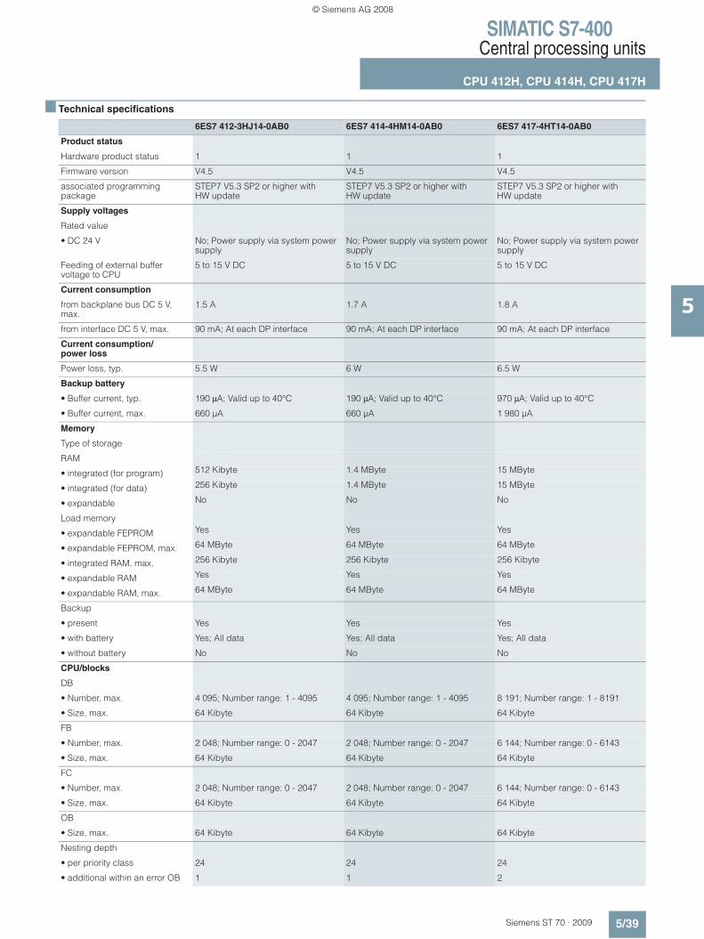
SIMATIC S7-400Central processing units
CPU 412H, CPU 414H, CPU 417H
5/39Siemens ST 70 · 2009
5
■ Technical specifications
6ES7 412-3HJ14-0AB0 6ES7 414-4HM14-0AB0 6ES7 417-4HT14-0AB0
Product status
Hardware product status 1 1 1
Firmware version V4.5 V4.5 V4.5
associated programming package
STEP7 V5.3 SP2 or higher with HW update
STEP7 V5.3 SP2 or higher with HW update
STEP7 V5.3 SP2 or higher with HW update
Supply voltages
Rated value
• DC 24 V No; Power supply via system power supply
No; Power supply via system power supply
No; Power supply via system power supply
Feeding of external buffer voltage to CPU
5 to 15 V DC 5 to 15 V DC 5 to 15 V DC
Current consumption
from backplane bus DC 5 V, max.
1.5 A 1.7 A 1.8 A
from interface DC 5 V, max. 90 mA; At each DP interface 90 mA; At each DP interface 90 mA; At each DP interface
Current consumption/power loss
Power loss, typ. 5.5 W 6 W 6.5 W
Backup battery
• Buffer current, typ. 190 μA; Valid up to 40°C 190 μA; Valid up to 40°C 970 μA; Valid up to 40°C
• Buffer current, max. 660 μA 660 μA 1 980 μA
Memory
Type of storage
RAM
• integrated (for program) 512 Kibyte 1.4 MByte 15 MByte
• integrated (for data) 256 Kibyte 1.4 MByte 15 MByte
• expandable No No No
Load memory
• expandable FEPROM Yes Yes Yes
• expandable FEPROM, max. 64 MByte 64 MByte 64 MByte
• integrated RAM, max. 256 Kibyte 256 Kibyte 256 Kibyte
• expandable RAM Yes Yes Yes
• expandable RAM, max. 64 MByte 64 MByte 64 MByte
Backup
• present Yes Yes Yes
• with battery Yes; All data Yes; All data Yes; All data
• without battery No No No
CPU/blocks
DB
• Number, max. 4 095; Number range: 1 - 4095 4 095; Number range: 1 - 4095 8 191; Number range: 1 - 8191
• Size, max. 64 Kibyte 64 Kibyte 64 Kibyte
FB
• Number, max. 2 048; Number range: 0 - 2047 2 048; Number range: 0 - 2047 6 144; Number range: 0 - 6143
• Size, max. 64 Kibyte 64 Kibyte 64 Kibyte
FC
• Number, max. 2 048; Number range: 0 - 2047 2 048; Number range: 0 - 2047 6 144; Number range: 0 - 6143
• Size, max. 64 Kibyte 64 Kibyte 64 Kibyte
OB
• Size, max. 64 Kibyte 64 Kibyte 64 Kibyte
Nesting depth
• per priority class 24 24 24
• additional within an error OB 1 1 2
© Siemens AG 2008
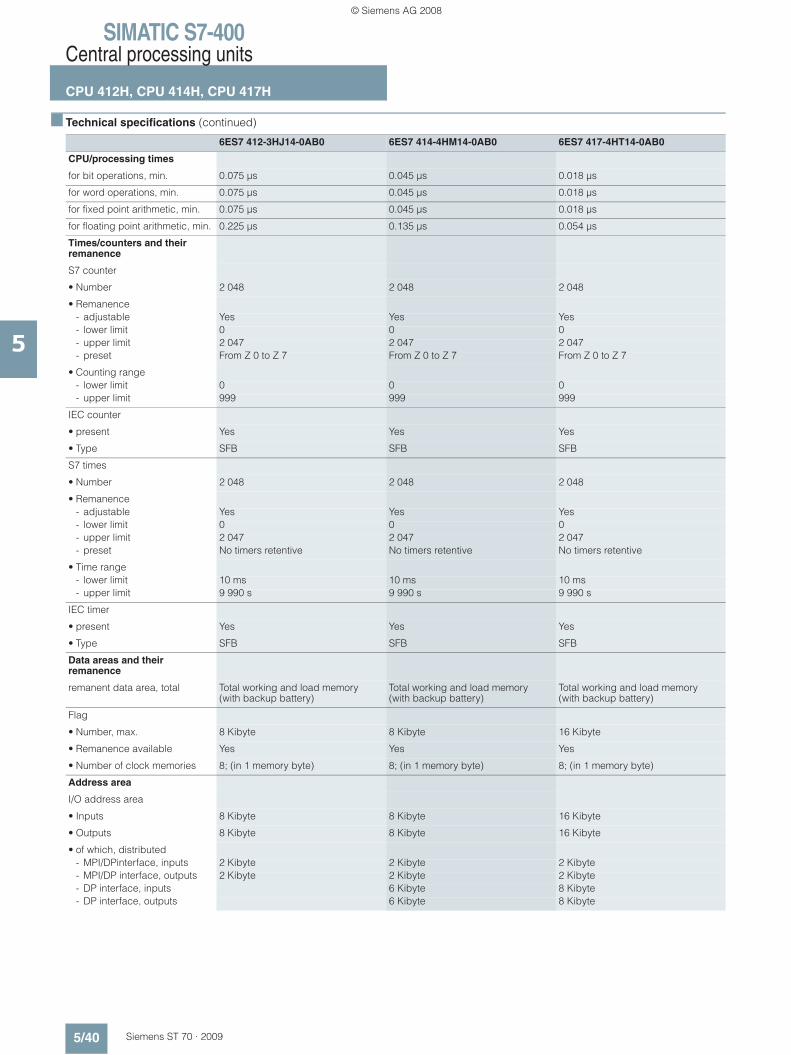
SIMATIC S7-400Central processing units
CPU 412H, CPU 414H, CPU 417H
5/40 Siemens ST 70 · 2009
5
■ Technical specifications (continued)
6ES7 412-3HJ14-0AB0 6ES7 414-4HM14-0AB0 6ES7 417-4HT14-0AB0
CPU/processing times
for bit operations, min. 0.075 μs 0.045 μs 0.018 μs
for word operations, min. 0.075 μs 0.045 μs 0.018 μs
for fixed point arithmetic, min. 0.075 μs 0.045 μs 0.018 μs
for floating point arithmetic, min. 0.225 μs 0.135 μs 0.054 μs
Times/counters and their remanence
S7 counter
• Number 2 048 2 048 2 048
• Remanence- adjustable Yes Yes Yes- lower limit 0 0 0- upper limit 2 047 2 047 2 047- preset From Z 0 to Z 7 From Z 0 to Z 7 From Z 0 to Z 7
• Counting range- lower limit 0 0 0- upper limit 999 999 999
IEC counter
• present Yes Yes Yes
• Type SFB SFB SFB
S7 times
• Number 2 048 2 048 2 048
• Remanence- adjustable Yes Yes Yes- lower limit 0 0 0- upper limit 2 047 2 047 2 047- preset No timers retentive No timers retentive No timers retentive
• Time range- lower limit 10 ms 10 ms 10 ms- upper limit 9 990 s 9 990 s 9 990 s
IEC timer
• present Yes Yes Yes
• Type SFB SFB SFB
Data areas and their remanence
remanent data area, total Total working and load memory (with backup battery)
Total working and load memory (with backup battery)
Total working and load memory (with backup battery)
Flag
• Number, max. 8 Kibyte 8 Kibyte 16 Kibyte
• Remanence available Yes Yes Yes
• Number of clock memories 8; (in 1 memory byte) 8; (in 1 memory byte) 8; (in 1 memory byte)
Address area
I/O address area
• Inputs 8 Kibyte 8 Kibyte 16 Kibyte
• Outputs 8 Kibyte 8 Kibyte 16 Kibyte
• of which, distributed- MPI/DPinterface, inputs 2 Kibyte 2 Kibyte 2 Kibyte- MPI/DP interface, outputs 2 Kibyte 2 Kibyte 2 Kibyte- DP interface, inputs 6 Kibyte 8 Kibyte- DP interface, outputs 6 Kibyte 8 Kibyte
© Siemens AG 2008
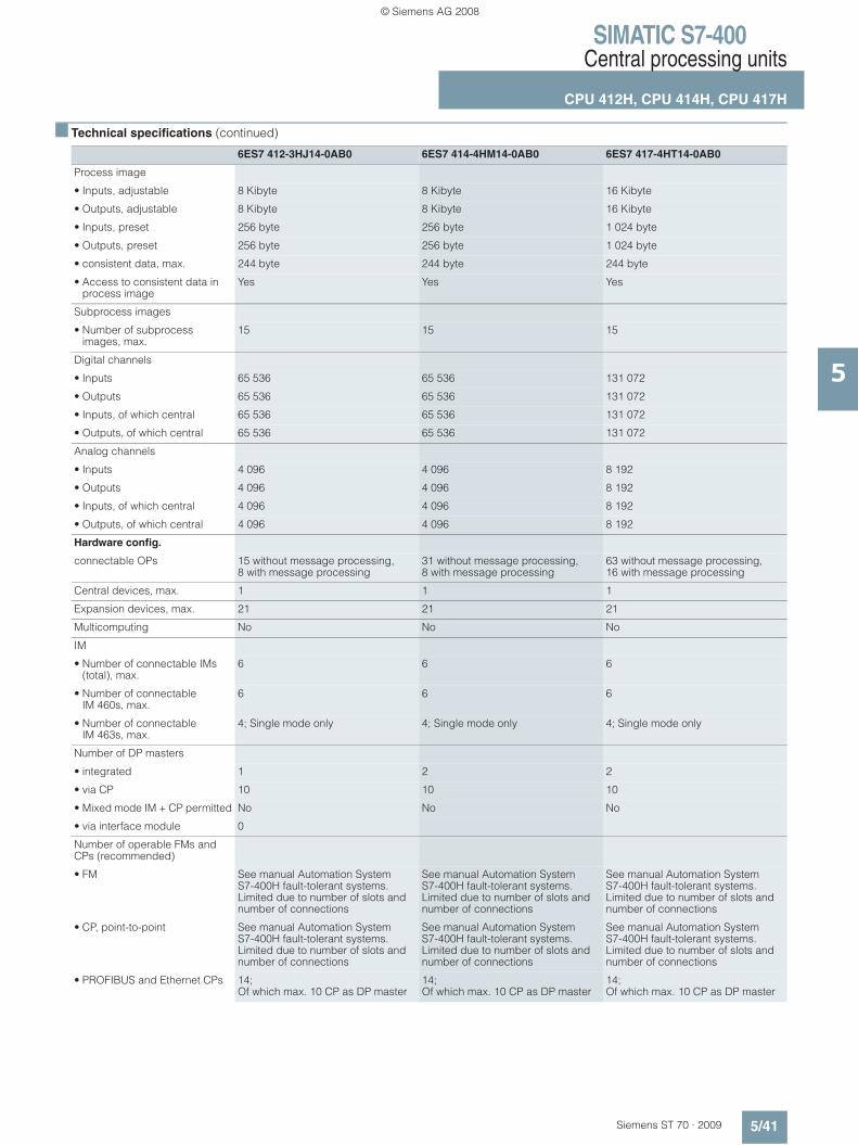
SIMATIC S7-400Central processing units
CPU 412H, CPU 414H, CPU 417H
5/41Siemens ST 70 · 2009
5
■ Technical specifications (continued)
6ES7 412-3HJ14-0AB0 6ES7 414-4HM14-0AB0 6ES7 417-4HT14-0AB0
Process image
• Inputs, adjustable 8 Kibyte 8 Kibyte 16 Kibyte
• Outputs, adjustable 8 Kibyte 8 Kibyte 16 Kibyte
• Inputs, preset 256 byte 256 byte 1 024 byte
• Outputs, preset 256 byte 256 byte 1 024 byte
• consistent data, max. 244 byte 244 byte 244 byte
• Access to consistent data in process image
Yes Yes Yes
Subprocess images
• Number of subprocess images, max.
15 15 15
Digital channels
• Inputs 65 536 65 536 131 072
• Outputs 65 536 65 536 131 072
• Inputs, of which central 65 536 65 536 131 072
• Outputs, of which central 65 536 65 536 131 072
Analog channels
• Inputs 4 096 4 096 8 192
• Outputs 4 096 4 096 8 192
• Inputs, of which central 4 096 4 096 8 192
• Outputs, of which central 4 096 4 096 8 192
Hardware config.
connectable OPs 15 without message processing, 8 with message processing
31 without message processing, 8 with message processing
63 without message processing, 16 with message processing
Central devices, max. 1 1 1
Expansion devices, max. 21 21 21
Multicomputing No No No
IM
• Number of connectable IMs (total), max.
6 6 6
• Number of connectable IM 460s, max.
6 6 6
• Number of connectable IM 463s, max.
4; Single mode only 4; Single mode only 4; Single mode only
Number of DP masters
• integrated 1 2 2
• via CP 10 10 10
• Mixed mode IM + CP permitted No No No
• via interface module 0
Number of operable FMs and CPs (recommended)
• FM See manual Automation System S7-400H fault-tolerant systems. Limited due to number of slots and number of connections
See manual Automation System S7-400H fault-tolerant systems. Limited due to number of slots and number of connections
See manual Automation System S7-400H fault-tolerant systems. Limited due to number of slots and number of connections
• CP, point-to-point See manual Automation System S7-400H fault-tolerant systems. Limited due to number of slots and number of connections
See manual Automation System S7-400H fault-tolerant systems. Limited due to number of slots and number of connections
See manual Automation System S7-400H fault-tolerant systems. Limited due to number of slots and number of connections
• PROFIBUS and Ethernet CPs 14; Of which max. 10 CP as DP master
14; Of which max. 10 CP as DP master
14; Of which max. 10 CP as DP master
© Siemens AG 2008
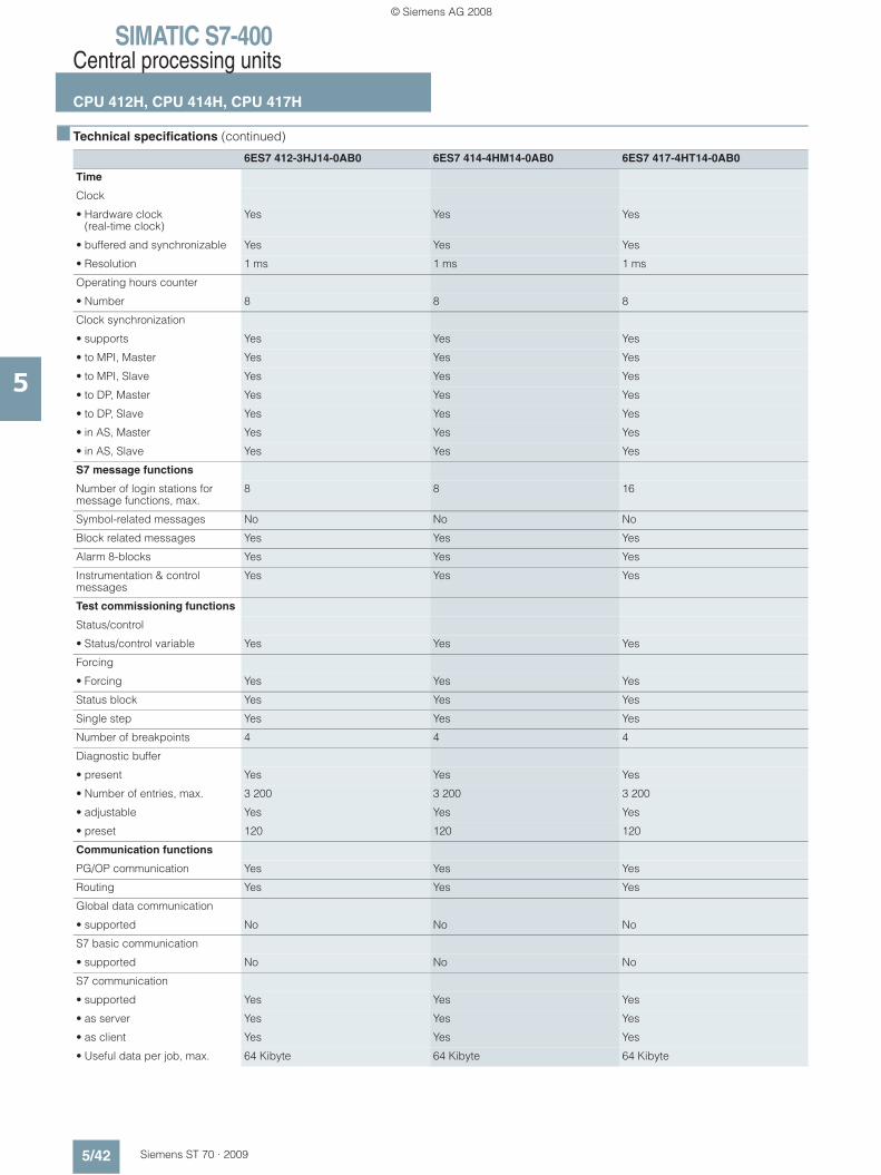
SIMATIC S7-400Central processing units
CPU 412H, CPU 414H, CPU 417H
5/42 Siemens ST 70 · 2009
5
■ Technical specifications (continued)
6ES7 412-3HJ14-0AB0 6ES7 414-4HM14-0AB0 6ES7 417-4HT14-0AB0
Time
Clock
• Hardware clock (real-time clock)
Yes Yes Yes
• buffered and synchronizable Yes Yes Yes
• Resolution 1 ms 1 ms 1 ms
Operating hours counter
• Number 8 8 8
Clock synchronization
• supports Yes Yes Yes
• to MPI, Master Yes Yes Yes
• to MPI, Slave Yes Yes Yes
• to DP, Master Yes Yes Yes
• to DP, Slave Yes Yes Yes
• in AS, Master Yes Yes Yes
• in AS, Slave Yes Yes Yes
S7 message functions
Number of login stations for message functions, max.
8 8 16
Symbol-related messages No No No
Block related messages Yes Yes Yes
Alarm 8-blocks Yes Yes Yes
Instrumentation & control messages
Yes Yes Yes
Test commissioning functions
Status/control
• Status/control variable Yes Yes Yes
Forcing
• Forcing Yes Yes Yes
Status block Yes Yes Yes
Single step Yes Yes Yes
Number of breakpoints 4 4 4
Diagnostic buffer
• present Yes Yes Yes
• Number of entries, max. 3 200 3 200 3 200
• adjustable Yes Yes Yes
• preset 120 120 120
Communication functions
PG/OP communication Yes Yes Yes
Routing Yes Yes Yes
Global data communication
• supported No No No
S7 basic communication
• supported No No No
S7 communication
• supported Yes Yes Yes
• as server Yes Yes Yes
• as client Yes Yes Yes
• Useful data per job, max. 64 Kibyte 64 Kibyte 64 Kibyte
© Siemens AG 2008

SIMATIC S7-400Central processing units
CPU 412H, CPU 414H, CPU 417H
5/43Siemens ST 70 · 2009
5
■ Technical specifications (continued)
6ES7 412-3HJ14-0AB0 6ES7 414-4HM14-0AB0 6ES7 417-4HT14-0AB0
S5-compatible communication
• supported Yes; (via CP -max. 10- and FC AG_SEND and FC AG_RECV)
Yes; (via CP -max. 10- and FC AG_SEND and FC AG_RECV)
Yes; (via CP -max. 10- and FC AG_SEND and FC AG_RECV)
• Useful data per job, max. 8 Kibyte 8 Kibyte 8 Kibyte
Standard communication (FMS)
• supported Yes; Via CP and loadable FB Yes; Via CP and loadable FB Yes; Via CP and loadable FB
Number of connections
• overall 16 32 64
1st interface
Physics RS 485 / PROFIBUS + MPI RS 485 / PROFIBUS + MPI RS 485 / PROFIBUS + MPI
isolated Yes Yes Yes
Functionality
• MPI Yes Yes Yes
• DP master Yes Yes Yes
• DP slave No No No
MPI
• Number of connections 16 32 44
• Services- PG/OP communication Yes Yes Yes- Routing Yes Yes Yes- Global data communication No No No- S7 basic communication No No No- S7 communication Yes Yes Yes
• Transmission speeds, max. 12 MBit/s 12 MBit/s 12 MBit/s
DP master
• Number of connections, max. 16 16 32
• Services- PG/OP communication Yes Yes Yes- Routing Yes Yes Yes- Global data communication No No No- S7 basic communication No No No- S7 communication Yes Yes Yes- S7 communication, as client Yes- S7 communication, as server Yes- equidistance support No No No- Activation/deactivation of
DP slavesNo No No
- direct data exchange (cross traffic)
No No No
• Transmission speeds, max. 12 MBit/s 12 MBit/s 12 MBit/s
• Number of DP slaves, max. 32 32 32
• Address area- Inputs, max. 2 Kibyte 2 Kibyte 2 Kibyte- Outputs, max. 2 Kibyte 2 Kibyte 2 Kibyte
• Useful data per DP slave- Inputs, max. 244 byte 244 byte 244 byte- Outputs, max. 244 byte 244 byte 244 byte
DP slave
• Number of connections No configuration of CPU as DP slave
© Siemens AG 2008

SIMATIC S7-400Central processing units
CPU 412H, CPU 414H, CPU 417H
5/44 Siemens ST 70 · 2009
5
■ Technical specifications (continued)
6ES7 412-3HJ14-0AB0 6ES7 414-4HM14-0AB0 6ES7 417-4HT14-0AB0
2nd interface
Physics RS 485 / PROFIBUS + MPI RS 485 / PROFIBUS + MPI
isolated Yes Yes
Functionality
• DP master Yes Yes
• DP slave No No
DP master
• Number of connections, max. 16 32
• Services- PG/OP communication Yes Yes- Routing Yes Yes- S7 basic communication No No- S7 communication Yes Yes- equidistance support No No- Activation/deactivation of
DP slavesNo
- direct data exchange (cross traffic)
No No
• Transmission speeds, max. 12 MBit/s 12 MBit/s
• Number of DP slaves, max. 96 125
• Address area- Inputs, max. 6 Kibyte 8 Kibyte- Outputs, max. 6 Kibyte 8 Kibyte
• Useful data per DP slave- Inputs, max. 244 byte 244 byte- Outputs, max. 244 byte 244 byte
3rd interface
Type of interfaces Pluggable synchronization submodule (FO)
Pluggable synchronization submodule (FO)
Pluggable synchronization submodule (FO)
pluggable interface module Synchronization submodule IF 960 6ES7 960-1AA04-0XA0
Synchronization submodule IF 960 6ES7 960-1AA04-0XA0 or 6ES7 960-1AB04-0XA0
Synchronization submodule IF 960 6ES7 960-1AA04-0XA0 or 6ES7 960-1AB04-0XA0
4th interface
Type of interface Pluggable synchronization submodule (FO)
Pluggable synchronizationsubmodule (FO)
Pluggable synchronization submodule (FO)
pluggable interface modules Synchronization submodule IF 960 6ES7 960-1AA04-0XA0
Synchronization submodule IF 960 6ES7 960-1AA04-0XA0 or 6ES7 960-1AB04-0XA0
Synchronization submodule IF 960 6ES7 960-1AA04-0XA0 or 6ES7 960-1AB04-0XA0
Isochronous mode
equidistance No
CiR configuration in RUN
CiR synchronization time, basic load
150 ms 100 ms 60 ms
CiR synchronization time, time per I/O slave
40 μs 25 μs 10 μs
© Siemens AG 2008
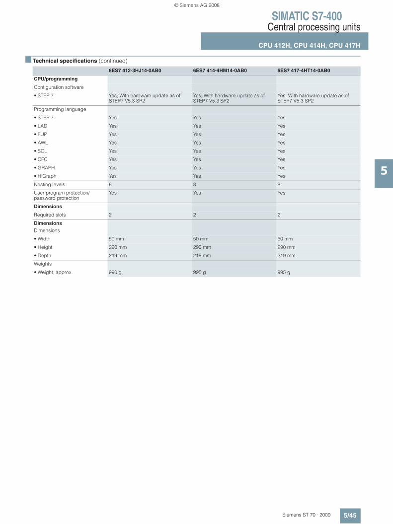
SIMATIC S7-400Central processing units
CPU 412H, CPU 414H, CPU 417H
5/45Siemens ST 70 · 2009
5
■ Technical specifications (continued)
6ES7 412-3HJ14-0AB0 6ES7 414-4HM14-0AB0 6ES7 417-4HT14-0AB0
CPU/programming
Configuration software
• STEP 7 Yes; With hardware update as of STEP7 V5.3 SP2
Yes; With hardware update as of STEP7 V5.3 SP2
Yes; With hardware update as of STEP7 V5.3 SP2
Programming language
• STEP 7 Yes Yes Yes
• LAD Yes Yes Yes
• FUP Yes Yes Yes
• AWL Yes Yes Yes
• SCL Yes Yes Yes
• CFC Yes Yes Yes
• GRAPH Yes Yes Yes
• HiGraph Yes Yes Yes
Nesting levels 8 8 8
User program protection/password protection
Yes Yes Yes
Dimensions
Required slots 2 2 2
Dimensions Dimensions
• Width 50 mm 50 mm 50 mm
• Height 290 mm 290 mm 290 mm
• Depth 219 mm 219 mm 219 mm
Weights
• Weight, approx. 990 g 995 g 995 g
© Siemens AG 2008
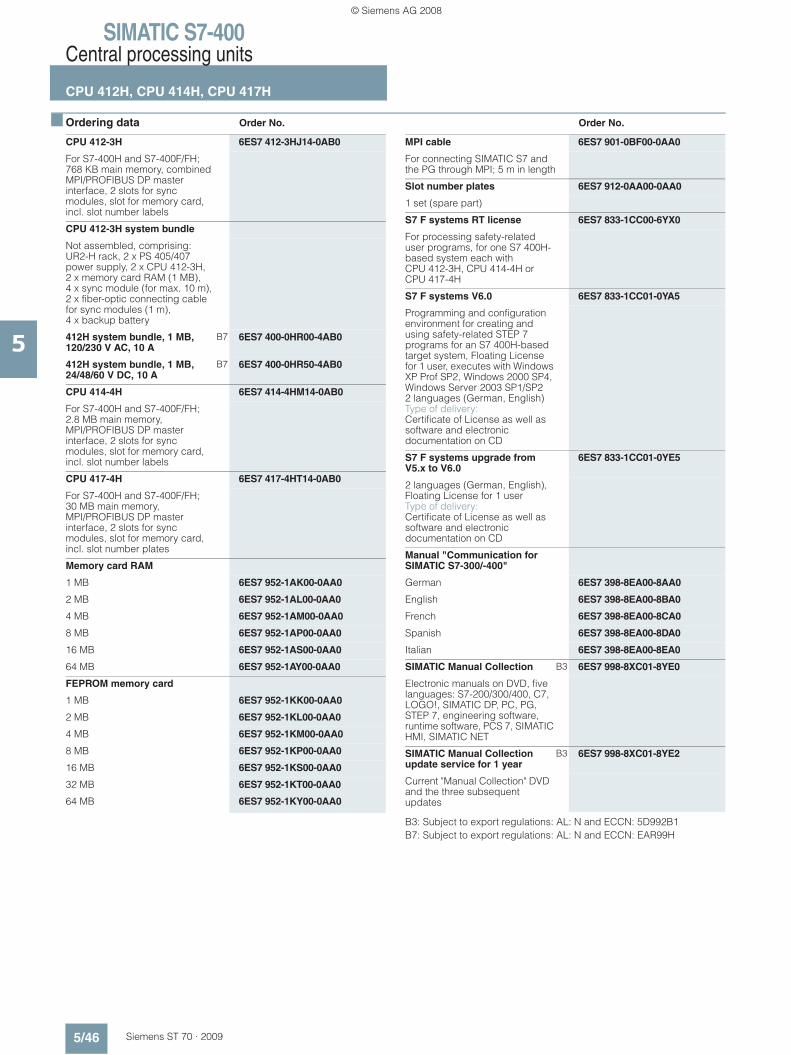
SIMATIC S7-400Central processing units
CPU 412H, CPU 414H, CPU 417H
5/46 Siemens ST 70 · 2009
5
■ Ordering data Order No. Order No.
B3: Subject to export regulations: AL: N and ECCN: 5D992B1B7: Subject to export regulations: AL: N and ECCN: EAR99H
CPU 412-3H 6ES7 412-3HJ14-0AB0
For S7-400H and S7-400F/FH;768 KB main memory, combined MPI/PROFIBUS DP master interface, 2 slots for sync modules, slot for memory card, incl. slot number labels
CPU 412-3H system bundle
Not assembled, comprising:UR2-H rack, 2 x PS 405/407 power supply, 2 x CPU 412-3H, 2 x memory card RAM (1 MB), 4 x sync module (for max. 10 m), 2 x fiber-optic connecting cable for sync modules (1 m), 4 x backup battery
412H system bundle, 1 MB, 120/230 V AC, 10 A
B7 6ES7 400-0HR00-4AB0
412H system bundle, 1 MB, 24/48/60 V DC, 10 A
B7 6ES7 400-0HR50-4AB0
CPU 414-4H 6ES7 414-4HM14-0AB0
For S7-400H and S7-400F/FH;2.8 MB main memory, MPI/PROFIBUS DP master interface, 2 slots for sync modules, slot for memory card, incl. slot number labels
CPU 417-4H 6ES7 417-4HT14-0AB0
For S7-400H and S7-400F/FH;30 MB main memory, MPI/PROFIBUS DP master interface, 2 slots for sync modules, slot for memory card, incl. slot number plates
Memory card RAM
1 MB 6ES7 952-1AK00-0AA0
2 MB 6ES7 952-1AL00-0AA0
4 MB 6ES7 952-1AM00-0AA0
8 MB 6ES7 952-1AP00-0AA0
16 MB 6ES7 952-1AS00-0AA0
64 MB 6ES7 952-1AY00-0AA0
FEPROM memory card
1 MB 6ES7 952-1KK00-0AA0
2 MB 6ES7 952-1KL00-0AA0
4 MB 6ES7 952-1KM00-0AA0
8 MB 6ES7 952-1KP00-0AA0
16 MB 6ES7 952-1KS00-0AA0
32 MB 6ES7 952-1KT00-0AA0
64 MB 6ES7 952-1KY00-0AA0
MPI cable 6ES7 901-0BF00-0AA0
For connecting SIMATIC S7 and the PG through MPI; 5 m in length
Slot number plates 6ES7 912-0AA00-0AA0
1 set (spare part)
S7 F systems RT license 6ES7 833-1CC00-6YX0
For processing safety-related user programs, for one S7 400H-based system each with CPU 412-3H, CPU 414-4H or CPU 417-4H
S7 F systems V6.0 6ES7 833-1CC01-0YA5
Programming and configuration environment for creating and using safety-related STEP 7 programs for an S7 400H-based target system, Floating License for 1 user, executes with Windows XP Prof SP2, Windows 2000 SP4, Windows Server 2003 SP1/SP22 languages (German, English)Type of delivery:Certificate of License as well as software and electronic documentation on CD
S7 F systems upgrade from V5.x to V6.0
6ES7 833-1CC01-0YE5
2 languages (German, English), Floating License for 1 userType of delivery:Certificate of License as well as software and electronic documentation on CD
Manual "Communication for SIMATIC S7-300/-400"
German 6ES7 398-8EA00-8AA0
English 6ES7 398-8EA00-8BA0
French 6ES7 398-8EA00-8CA0
Spanish 6ES7 398-8EA00-8DA0
Italian 6ES7 398-8EA00-8EA0
SIMATIC Manual Collection B3 6ES7 998-8XC01-8YE0
Electronic manuals on DVD, five languages: S7-200/300/400, C7, LOGO!, SIMATIC DP, PC, PG, STEP 7, engineering software, runtime software, PCS 7, SIMATIC HMI, SIMATIC NET
SIMATIC Manual Collection update service for 1 year
B3 6ES7 998-8XC01-8YE2
Current "Manual Collection" DVD and the three subsequent updates
© Siemens AG 2008

SIMATIC S7-400Central processing units
CPU 412H, CPU 414H, CPU 417H
5/47Siemens ST 70 · 2009
5
■ Ordering data Order No. Order No.
Brochure "SIMATIC S7-400 automation system - design and application"
German 6ES7 498-8AA00-8AB0
English 6ES7 498-8AA00-8BB0
RS 485 bus connector with 90° cable outlet
Max. transmission rate 12 Mbit/s
Without programming device interface
6ES7 972-0BA12-0XA0
With programming device interface
6ES7 972-0BB12-0XA0
RS 485 bus connector with angular cable outlet
Max. transmission rate 12 Mbit/s
Without programming device interface
6ES7 972-0BA41-0XA0
With programming device interface
6ES7 972-0BB41-0XA0
Max. transmission rate 1.5 Mbit/s
Without programming device interface
6ES7 972-0BA30-0XA0
RS 485 bus connector with 90° cable outlet for FastConnect connection system
Max. transmission rate 12 Mbit/s
Without programming device interface
6ES7 972-0BA51-0XA0
With programming device interface
6ES7 972-0BB51-0XA0
RS 485 bus connector with axial cable outlet
For SIMATIC OP, for connecting to PPI, MPI, PROFIBUS
6GK1 500-0EA02
PROFIBUS FastConnect bus cable
Standard type with special design for quick mounting, 2-core, shielded, sold by the meter, max. delivery unit 1000 m, minimum ordering quantity 20 m
6XV1 830-0EH10
© Siemens AG 2008

SIMATIC S7-400Central processing units
CPU 416F
5/48 Siemens ST 70 · 2009
5
■ Overview
• For constructing a fail-safe automation system for plants with increased safety requirements
• High-performance CPU in the top-end performance range • Satisfies safety requirements up to SIL 3 acc. to IEC 61508
and Cat. 4 acc. to EN 954-1• Standard and safety-related tasks can be performed with a
single CPU• Multi-processor mode is possible• Safety-related communication with distributed I/O devices
over PROFIBUS DP with the PROFIsafe profile• Fail-safe I/O modules can be connected decentralized over
the integrated interfaces (DP and PN with CPU 416F-3 PN/DP) and/or through communication modules (CP 443-5 Ext. and CP 443-1 Adv.)
• Standard modules for non-safety-related applications can be operated centrally and decentralized
■ Technical specifications
6ES7 416-2FN05-0AB0
6ES7 416-3FR05-0AB0
Product status
Firmware version V5.0 V5.0
associated programming package
STEP7 V5.3 SP2 or higher with HW-update
STEP7 V5.4 SP1 or higher
Feeding of external buffer voltage to CPU
5 to 15 V DC 5 to 15 V DC
Current consumption
from backplane bus DC 5 V, max.
1.1 A 1.3 A
from interface DC 5 V, max. 90 mA; At each DP interface
90 mA; At each DP interface
Current consumption/power loss
Power loss, typ. 4 W 4.5 W
Backup battery
• Buffer current, typ. 125 μA; Valid up to 40°C
125 μA; Valid up to 40°C
• Buffer current, max. 550 μA 550 μA
Memory
Type of storage
RAM
• integrated (for program) 2.8 MByte 5.6 MByte
• integrated (for data) 2.8 MByte 5.6 MByte
• expandable No No
Load memory
• expandable FEPROM Yes Yes
• expandable FEPROM, max.
64 MByte 64 MByte
• integrated RAM, max. 1 MByte 1 MByte
• expandable RAM Yes Yes
• expandable RAM, max. 64 MByte 64 MByte
Backup
• present Yes Yes
• with battery Yes Yes
• without battery No No
6ES7 416-2FN05-0AB0
6ES7 416-3FR05-0AB0
CPU/blocks
DB
• Number, max. 10 000; Number range: 1 to 16,000
10 000; Number range: 1 to 16,000
• Size, max. 64 Kibyte 64 Kibyte
FB
• Number, max. 5 000; Number range: 0 to 7999
5 000; Number range: 0 to 7999
• Size, max. 64 Kibyte 64 Kibyte
FC
• Number, max. 5 000; Number range: 0 to 7,999
5 000; Number range: 0 to 7,999
• Size, max. 64 Kibyte 64 Kibyte
OB
• Size, max. 64 Kibyte 64 Kibyte
Nesting depth
• per priority class 24 24
• additional within an error OB
2 2
CPU/processing times
for bit operations, min. 30 ns 30 ns
for word operations, min. 30 ns 30 ns
for fixed point arithmetic, min.
30 ns 30 ns
for floating point arithmetic, min.
90 ns 90 ns
Times/counters and their remanence
S7 counter
• Number 2 048 2 048
© Siemens AG 2008

SIMATIC S7-400Central processing units
CPU 416F
5/49Siemens ST 70 · 2009
5
■ Technical specifications (continued)
6ES7 416-2FN05-0AB0
6ES7 416-3FR05-0AB0
S7 counter (continued)
• Remanence- adjustable Yes Yes- lower limit 0 0- upper limit 2 047 2 047- preset From Z 0 to Z 7 From Z 0 to Z 7
• Counting range- lower limit 0 0- upper limit 999 999
IEC counter
• present Yes Yes
• Type SFB SFB
S7 times
• Number 2 048 2 048
• Remanence- adjustable Yes Yes- lower limit 0 0- upper limit 2 047 2 047- preset No times retentive No times retentive
• Time range- lower limit 10 ms 10 ms- upper limit 9 990 s 9 990 s
IEC timer
• present Yes Yes
• Type SFB SFB
Data areas and their remanence
remanent data area, total Total working and load memory (with backup battery)
Total working and load memory (with backup battery)
Flag
• Number, max. 16 Kibyte 16 Kibyte
• Remanence available Yes Yes
• Number of clock memories 8; (in 1 memory byte)
8; (in 1 memory byte)
Address area
I/O address area
• Inputs 16 Kibyte 16 Kibyte
• Outputs 16 Kibyte 16 Kibyte
• of which, distributed- MPI/DPinterface, inputs 2 Kibyte 2 Kibyte- MPI/DP interface,
outputs2 Kibyte 2 Kibyte
- DP interface, inputs 8 Kibyte 8 Kibyte- DP interface, outputs 8 Kibyte 8 Kibyte
Process image
• Inputs, adjustable 16 Kibyte 16 Kibyte
• Outputs, adjustable 16 Kibyte 16 Kibyte
• Inputs, preset 512 byte 512 byte
• Outputs, preset 512 byte 512 byte
• consistent data, max. 244 byte 244 byte
• Access to consistent data in process image
Yes Yes
6ES7 416-2FN05-0AB0
6ES7 416-3FR05-0AB0
Subprocess images
• Number of subprocess images, max.
15 15
Digital channels
• Inputs 131 072 131 072
• Outputs 131 072 131 072
• Inputs, of which central 131 072 131 072
• Outputs, of which central 131 072 131 072
Analog channels
• Inputs 8 192 8 192
• Outputs 8 192 8 192
• Inputs, of which central 8 192 8 192
• Outputs, of which central 8 192 8 192
Hardware config.
connectable OPs 63 63
Central devices, max. 1 1
Expansion devices, max. 21 21
Multicomputing Yes; Max. 4 CPUs (with UR1 or UR2)
Yes; Max. 4 CPUs (with UR1 or UR2)
IM
• Number of connectable IMs (total), max.
6 6
• Number of connectable IM 460s, max.
6 6
• Number of connectable IM 463s, max.
4; IM 463-2 4; IM 463-2
Number of DP masters
• integrated 2 2
• via IM 467 4 4
• via CP 10; CP 443-5 Extended
10; CP 443-5 Extended
• Mixed mode IM + CP permitted
No; IM 467 cannot be used with CP 443-5 Ext.; IM 467 cannot be used with CP 443-1 EX40 in PN IO mode
No; IM 467 cannot be used with CP 443-5 Ext.; IM 467 cannot be used with CP 443-1 EX40 in PN IO mode
• via interface module 0 1
• Number of pluggable S5 modules (via adapter capsule in central device), max.
6 6
Number of IO controllers
• integrated• via CP 4;
Via CP 443-1 EX 41 in PN mode; max. 4 in central controller
4; Via CP 443-1 EX 41 in PN mode; max. 4 in central controller
Number of operable FMs and CPs (recommended)
• FM Limited due to number of slots and number of connec-tions
Limited due to number of slots and number of connec-tions
© Siemens AG 2008

SIMATIC S7-400Central processing units
CPU 416F
5/50 Siemens ST 70 · 2009
5
■ Technical specifications (continued)
6ES7 416-2FN05-0AB0
6ES7 416-3FR05-0AB0
Number of operable FMs and CPs (recommended) (cont.)
• CP, point-to-point Limited due to number of slots and number of connec-tions
Limited due to number of slots and number of connec-tions
• PROFIBUS and Ethernet CPs
14; Of which 10 CP or IM max. as DP master and PN controller
14; Of which 10 CP/IM max. as DP master and PN controller
Time
Clock
• Hardware clock (real-time clock)
Yes Yes
• buffered and synchroni-zable
Yes Yes
• Resolution 1 ms 1 ms
Operating hours counter
• Number 8 8
Clock synchronization
• supports Yes Yes
• to MPI, Master Yes Yes
• to MPI, Slave Yes Yes
• to DP, Master Yes Yes
• to DP, Slave Yes Yes
• in AS, Master Yes Yes
• in AS, Slave Yes Yes
• on Ethernet via NTP Via CP Via CP
• to IF 964 DP Yes
S7 message functions
Number of login stations for message functions, max.
63; Max. 63 with ALARM_S and ALARM_D (OPs); max. 12 with ALARM_8 and ALARM_P (e.g. WinCC)
63; Max. 63 with ALARM_S and ALARM_D (OPs); max. 12 with ALARM_8 and ALARM_P (e.g. WinCC)
Symbol-related messages Yes Yes
Number of messages
• overall, max. 1 024 1 024
Block related messages Yes Yes
Alarm 8-blocks Yes Yes
Instrumentation & control messages
Yes Yes
Test commissioning functions
Status/control
• Status/control variable Yes Yes
Forcing
• Forcing Yes Yes
Status block Yes Yes
Single step Yes Yes
Number of breakpoints 4 4
6ES7 416-2FN05-0AB0
6ES7 416-3FR05-0AB0
Diagnostic buffer
• present Yes Yes
• Number of entries, max. 3 200 3 200
• adjustable Yes Yes
• preset 120 120
Communication functions
PG/OP communication Yes Yes
Routing Yes Yes
Global data communication
• supported Yes Yes
• Size of GD packets, max. 54 byte 54 byte
S7 basic communication
• supported Yes Yes
• Useful data per job, max. 76 byte 76 byte
S7 communication
• supported Yes Yes
• Useful data per job, max. 64 Kibyte 64 Kibyte
S5-compatible communication
• supported Yes; (via CP max. 10 and FC AG_SEND and FC AG_RECV)
Yes; (via CP max. 10 and FC AG_SEND and FC AG_RECV)
• Useful data per job, max. 8 Kibyte 8 Kibyte
Standard communication (FMS)
• supported Yes; Via CP and loadable FB
Yes; Via CP and loadable FB
Web server
• Web server No; Via CP Yes; Read-only function
Open IE communication
• TCP/IP Yes- Number of connections,
max.64
- Data length, max. 32 Kibyte
• ISO-on-TCP (RFC1006) Via CP 443-1 Adv. and loadable FB
Yes
- Number of connections, max.
64
- Data length, max. 1452 32 Kibyte; 1452 bytes via CP 443-1 Adv.
• UDP Yes- Number of connections,
max.64
- Data length, max. 1 472 byte
Number of connections
• overall 64 64
© Siemens AG 2008
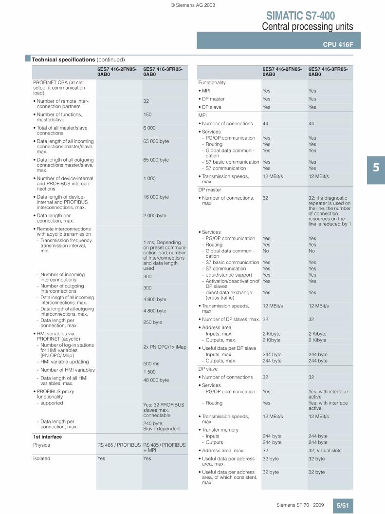
SIMATIC S7-400Central processing units
CPU 416F
5/51Siemens ST 70 · 2009
5
■ Technical specifications (continued)
6ES7 416-2FN05-0AB0
6ES7 416-3FR05-0AB0
PROFINET CBA (at set setpoint communication load)
• Number of remote inter-connection partners
32
• Number of functions, master/slave
150
• Total of all master/slave connections
6 000
• Data length of all incoming connections master/slave, max.
65 000 byte
• Data length of all outgoing connections master/slave, max.
65 000 byte
• Number of device-internal and PROFIBUS intercon-nections
1 000
• Data length of device-internal and PROFIBUS interconnections, max.
16 000 byte
• Data length per connection, max.
2 000 byte
• Remote interconnections with acyclic transmission- Transmission frequency:
transmission interval, min.
1 ms; Depending on preset communi-cation load, number of interconnections and data length used
- Number of incoming interconnections
300
- Number of outgoing interconnections
300
- Data length of all incoming interconnections, max.
4 800 byte
- Data length of all outgoing interconnections, max.
4 800 byte
- Data length per connection, max.
250 byte
• HMI variables via PROFINET (acyclic)- Number of log-in stations
for HMI variables (PN OPC/iMap)
2x PN OPC/1x iMap
- HMI variable updating 500 ms- Number of HMI variables 1 500- Data length of all HMI
variables, max.48 000 byte
• PROFIBUS proxy functionality- supported Yes; 32 PROFIBUS
slaves max. connectable
- Data length per connection, max.
240 byte; Slave-dependent
1st interface
Physics RS 485 / PROFIBUS RS 485 / PROFIBUS + MPI
isolated Yes Yes
6ES7 416-2FN05-0AB0
6ES7 416-3FR05-0AB0
Functionality
• MPI Yes Yes
• DP master Yes Yes
• DP slave Yes Yes
MPI
• Number of connections 44 44
• Services- PG/OP communication Yes Yes- Routing Yes Yes- Global data communi-
cationYes Yes
- S7 basic communication Yes Yes- S7 communication Yes Yes
• Transmission speeds, max.
12 MBit/s 12 MBit/s
DP master
• Number of connections, max.
32 32; if a diagnostic repeater is used on the line, the number of connection resources on the line is reduced by 1
• Services- PG/OP communication Yes Yes- Routing Yes Yes- Global data communi-
cationNo No
- S7 basic communication Yes Yes- S7 communication Yes Yes- equidistance support Yes Yes- Activation/deactivation of
DP slavesYes Yes
- direct data exchange (cross traffic)
Yes Yes
• Transmission speeds, max.
12 MBit/s 12 MBit/s
• Number of DP slaves, max. 32 32
• Address area- Inputs, max. 2 Kibyte 2 Kibyte- Outputs, max. 2 Kibyte 2 Kibyte
• Useful data per DP slave- Inputs, max. 244 byte 244 byte- Outputs, max. 244 byte 244 byte
DP slave
• Number of connections 32 32
• Services- PG/OP communication Yes Yes; with interface
active- Routing Yes Yes; with interface
active
• Transmission speeds, max.
12 MBit/s 12 MBit/s
• Transfer memory- Inputs 244 byte 244 byte- Outputs 244 byte 244 byte
• Address area, max. 32 32; Virtual slots
• Useful data per address area, max.
32 byte 32 byte
• Useful data per address area, of which consistent, max.
32 byte 32 byte
© Siemens AG 2008

SIMATIC S7-400Central processing units
CPU 416F
5/52 Siemens ST 70 · 2009
5
■ Technical specifications (continued)
6ES7 416-2FN05-0AB0
6ES7 416-3FR05-0AB0
2nd interface
Physics RS 485 / PROFIBUS Ethernet
isolated Yes Yes
Functionality
• DP master Yes No
• DP slave Yes No
• PROFINET IO controller Yes
• PROFINET CBA Yes
• Point-to-point coupling No
DP master
• Number of connections, max.
32
• Services- PG/OP communication Yes- Routing Yes- S7 basic communication Yes- S7 communication Yes- equidistance support Yes- Activation/deactivation of
DP slavesYes
- direct data exchange (cross traffic)
Yes
• Transmission speeds, max.
12 MBit/s
• Number of DP slaves, max. 125
• Address area- Inputs, max. 8 Kibyte- Outputs, max. 8 Kibyte
• Useful data per DP slave- Inputs, max. 244 byte- Outputs, max. 244 byte
DP slave
• Number of connections 32
• Services- Routing Yes- Programming Yes
• GSD file http://support.automation.siemens.com/WW/view/en/113652
• Transmission speeds, max.
12 MBit/s
• Transfer memory- Inputs 244 byte- Outputs 244 byte
• Address area, max. 32
• Useful data per address area, max.
32 byte
• Useful data per address area, of which consistent, max.
32 byte
6ES7 416-2FN05-0AB0
6ES7 416-3FR05-0AB0
PROFINET IO controller
• Services- PG/OP communication Yes- Routing Yes; Routing of PG
functions- S7 communication Yes- open IE communication Yes
• Transmission rate, min. 10 MBit/s
• Transmission speed, max. 100 MBit/s
• Total number of connectable IO Devices, max.
256
• Updating time 250 μs to 512 ms; minimum value dependent on preset communi-cation share for PROFINET I/O, of number of I/O devices and number of configured user data
• Address area- Inputs, max. 8 Kibyte- Outputs, max. 8 Kibyte- Useful data consistency,
max.255 byte; incl. net data accompaniers
PROFINET CBA
• Acyclic transmission Yes
• cyclic transmission Yes
3rd interface
Type of interfaces Pluggable interface module (IF), technical specifica-tions as for 2nd interface
pluggable interface module IF 964-DP (Order No.: 6ES7 964-2AA04-0AB0)
Physics RS 485 / PROFIBUS
isolated Yes
power supply to interface (15 to 30 V DC), max.
150 mA
Number of connection resources
32
Functionality
• MPI No
• DP master Yes
• DP slave Yes
© Siemens AG 2008

SIMATIC S7-400Central processing units
CPU 416F
5/53Siemens ST 70 · 2009
5
■ Technical specifications (continued)
6ES7 416-2FN05-0AB0
6ES7 416-3FR05-0AB0
DP master
• Number of connections, max.
32
• Services- PG/OP communication Yes- Routing Yes- Global data communi-
cationNo
- S7 basic communication Yes- S7 communication Yes- Equidistance support Yes- SYNC/FREEZE Yes- Activation/deactivation of
DP slavesYes
- Direct data exchange Yes
• Transmission rate, max. 12 MBit/s
• Number of DP slaves, max. 125
• Address area- Inputs, max. 8 Kibyte- Outputs, max. 8 Kibyte
• Useful data per DP slave- Useful data per DP slave,
max.244 byte
- Inputs, max. 244 byte- Outputs, max. 244 byte- Slots, max. 244- per slot, max. 128 byte
DP slave
• Number of connections 32
• Services- Routing Yes; When interface
active- Status/control Yes; When interface
active
• GSD file http://support.automation.siemens.com/WW/view/en/113652
• Transmission rate, max. 12 MBit/s
• Transfer memory- Inputs 244 byte- Outputs 244 byte
• Address range, max. 32
• Useful data per address area, max.
32 byte
• Useful data per address area, of which consistent, max.
32 byte
6ES7 416-2FN05-0AB0
6ES7 416-3FR05-0AB0
Isochronous mode
Useful data per isoch-ronous slave, max.
244 byte 244 byte
equidistance Yes Yes
shortest clock pulse 1 ms; 0.5 ms without use of SFC 126, 127
1 ms; Without use of SFC 126 and 127 up to 0.5 ms
CiR configuration in RUN
CiR synchronization time, basic load
100 ms 100 ms
CiR synchronization time, time per I/O slave
40 μs 40 μs
CPU/programming
Configuration software
• STEP 7 Yes Yes
Programming language
• STEP 7 Yes
• LAD Yes Yes
• FUP Yes Yes
• AWL Yes Yes
• SCL Yes Yes
• CFC Yes Yes
• GRAPH Yes Yes
• HiGraph Yes Yes
Nesting levels 7 7
User program protection/password protection
Yes Yes
Dimensions
Required slots 1 2
Dimensions
Dimensions
• Width 25 mm 50 mm
• Height 290 mm 290 mm
• Depth 219 mm 219 mm
Weights
• Weight, approx. 720 g 900 g
© Siemens AG 2008
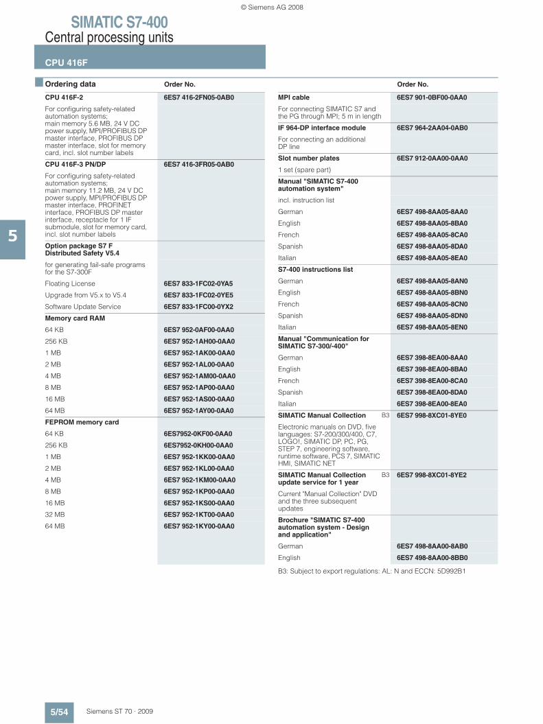
SIMATIC S7-400Central processing units
CPU 416F
5/54 Siemens ST 70 · 2009
5
■ Ordering data Order No. Order No.
B3: Subject to export regulations: AL: N and ECCN: 5D992B1
CPU 416F-2 6ES7 416-2FN05-0AB0
For configuring safety-related automation systems;main memory 5.6 MB, 24 V DC power supply, MPI/PROFIBUS DP master interface, PROFIBUS DP master interface, slot for memory card, incl. slot number labels
CPU 416F-3 PN/DP 6ES7 416-3FR05-0AB0
For configuring safety-related automation systems;main memory 11.2 MB, 24 V DC power supply, MPI/PROFIBUS DP master interface, PROFINET interface, PROFIBUS DP master interface, receptacle for 1 IF submodule, slot for memory card, incl. slot number labels
Option package S7 F Distributed Safety V5.4
for generating fail-safe programs for the S7-300F
Floating License 6ES7 833-1FC02-0YA5
Upgrade from V5.x to V5.4 6ES7 833-1FC02-0YE5
Software Update Service 6ES7 833-1FC00-0YX2
Memory card RAM
64 KB 6ES7 952-0AF00-0AA0
256 KB 6ES7 952-1AH00-0AA0
1 MB 6ES7 952-1AK00-0AA0
2 MB 6ES7 952-1AL00-0AA0
4 MB 6ES7 952-1AM00-0AA0
8 MB 6ES7 952-1AP00-0AA0
16 MB 6ES7 952-1AS00-0AA0
64 MB 6ES7 952-1AY00-0AA0
FEPROM memory card
64 KB 6ES7952-0KF00-0AA0
256 KB 6ES7952-0KH00-0AA0
1 MB 6ES7 952-1KK00-0AA0
2 MB 6ES7 952-1KL00-0AA0
4 MB 6ES7 952-1KM00-0AA0
8 MB 6ES7 952-1KP00-0AA0
16 MB 6ES7 952-1KS00-0AA0
32 MB 6ES7 952-1KT00-0AA0
64 MB 6ES7 952-1KY00-0AA0
MPI cable 6ES7 901-0BF00-0AA0
For connecting SIMATIC S7 and the PG through MPI; 5 m in length
IF 964-DP interface module 6ES7 964-2AA04-0AB0
For connecting an additional DP line
Slot number plates 6ES7 912-0AA00-0AA0
1 set (spare part)
Manual "SIMATIC S7-400 automation system"
incl. instruction list
German 6ES7 498-8AA05-8AA0
English 6ES7 498-8AA05-8BA0
French 6ES7 498-8AA05-8CA0
Spanish 6ES7 498-8AA05-8DA0
Italian 6ES7 498-8AA05-8EA0
S7-400 instructions list
German 6ES7 498-8AA05-8AN0
English 6ES7 498-8AA05-8BN0
French 6ES7 498-8AA05-8CN0
Spanish 6ES7 498-8AA05-8DN0
Italian 6ES7 498-8AA05-8EN0
Manual "Communication for SIMATIC S7-300/-400"
German 6ES7 398-8EA00-8AA0
English 6ES7 398-8EA00-8BA0
French 6ES7 398-8EA00-8CA0
Spanish 6ES7 398-8EA00-8DA0
Italian 6ES7 398-8EA00-8EA0
SIMATIC Manual Collection B3 6ES7 998-8XC01-8YE0
Electronic manuals on DVD, five languages: S7-200/300/400, C7, LOGO!, SIMATIC DP, PC, PG, STEP 7, engineering software, runtime software, PCS 7, SIMATIC HMI, SIMATIC NET
SIMATIC Manual Collection update service for 1 year
B3 6ES7 998-8XC01-8YE2
Current "Manual Collection" DVD and the three subsequent updates
Brochure "SIMATIC S7-400 automation system - Design and application"
German 6ES7 498-8AA00-8AB0
English 6ES7 498-8AA00-8BB0
© Siemens AG 2008

SIMATIC S7-400Central processing units
CPU 416F
5/55Siemens ST 70 · 2009
5
■ Ordering data Order No. Order No.
PROFIBUS bus components
RS 485 bus connector with 90° cable outlet
Max. transfer rate 12 Mbit/s
Without PG interface 6ES7 972-0BA12-0XA0
With PG interface 6ES7 972-0BB12-0XA0
RS 485 bus connector with angled cable outlet
Max. transfer rate 12 Mbit/s
Without PG interface 6ES7 972-0BA41-0XA0
With PG interface 6ES7 972-0BB41-0XA0
RS 485 bus connector with 90° cable outlet for FastConnect system
Max. transfer rate 12 Mbit/s
Without PG interface 6ES7 972-0BA51-0XA0
With PG interface 6ES7 972-0BB51-0XA0
RS 485 bus connector with axial cable outlet
For SIMATIC OP, for connection to PPI, MPI, PROFIBUS
6GK1 500-0EA02
PROFIBUS FastConnect bus cable
Standard type with special design for quick mounting, 2-core, shielded, sold by the meter, max. delivery unit 1000 m, minimum order quantity 20 m
6XV1 830-0EH10
RS 485 repeater for PROFIBUS 6ES7 972-0AA01-0XA0
Data transfer rate up to 12 Mbit/s; 24 V DC; IP20 housing
PROFINET bus components
IE FC TP Standard Cable GP 2x2
6XV1 840-2AH10
4-core, shielded TP installation cable for connection to IE FC Outlet RJ45/ IE FC RJ45 Plug; PROFINET-compatible; with UL approval; sold by the meter
FO Standard Cable GP (50/125) 6XV1 873-2A
Standard cable, splittable, UL approval, sold by the meter
SCALANCE X204-2 Industrial Ethernet Switch
6GK5 204-2BB10-2AA3
Industrial Ethernet Switches with integral SNMP access, web diagnostics, copper cable diagnostics and PROFINET diagnostics for configuring line, star and ring topologies; four 10/100 Mbit/s RJ45 ports and two FO ports
IE FC RJ45 plugs
RJ45 plug connector for Industrial Ethernet with a rugged metal enclosure and integrated insulation displacement contacts for connecting Industrial Ethernet FC installation cables
IE FC RJ45 plug 180
180° cable outlet
1 unit 6GK1 901-1BB10-2AA0
10 units 6GK1 901-1BB10-2AB0
50 units 6GK1 901-1BB10-2AE0
PROFIBUS/PROFINET bus components
see Catalogs IK PI, CA 01
For establishing MPI/PROFIBUS/PROFINET communication
© Siemens AG 2008
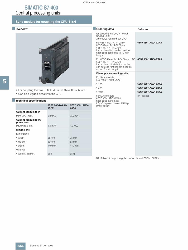
SIMATIC S7-400Central processing units
Sync module for coupling the CPU 41xH
5/56 Siemens ST 70 · 2009
5
■ Overview
• For coupling the two CPU 41xH in the S7-400H subunits.• Can be plugged direct into the CPU
■ Technical specifications
■ Ordering data Order No.
B7: Subject to export regulations: AL: N and ECCN: EAR99H
6ES7 960-1AA04-0XA0
6ES7 960-1AB04-0XA0
Current consumption
from CPU, max. 210 mA 250 mA
Current consumption/power loss Power loss, typ. 1.1 mW 1.3 mW
Dimensions
Dimensions
• Width 25 mm 25 mm
• Height 53 mm 53 mm
• Depth 140 mm 140 mm
Weights
• Weight, approx. 65 g 65 g
for coupling the CPU 41xH for S7-400H/F/FH; 2 modules required per CPU;
For 6ES7 412-3HJ14-0AB0, 6ES7 414-4HM14-0AB0 and 6ES7 417-4HT14-0AB0; for patch cable, can be used for fiber-optic cables up to 10 m in length
6ES7 960-1AA04-0XA0
For 6ES7 414-4HM14-0AB0 and 6ES7 417-4HT14-0AB0; for patch and installation cables, can be used for fiber-optic cables up to 10 km in length
B7 6ES7 960-1AB04-0XA0
Fiber-optic connecting cable
For Sync module 6ES7 960-1Ax04-0XA0
• 1 m 6ES7 960-1AA04-5AA0
• 2 m 6ES7 960-1AA04-5BA0
• 10 m 6ES7 960-1AA04-5KA0
For Sync module 6ES7 960-1AB04-0XA0;fiber-optic monomode LC/LC duplex crossed 9/125 μ (max. 10 km)
on request
© Siemens AG 2008

SIMATIC S7-400Central processing units
IF-964 DP PROFIBUS module
5/57Siemens ST 70 · 2009
5
■ Overview
• To connect distributed I/Os over PROFIBUS DP• Max. transmission rate 12 Mbit/s• Electrically isolated RS 485 interface• Connection via 9-pin sub-D connector• One or two PROFIBUS modules can be inserted per S7-400
CPU: - CPU 414-3/416-3: 1 module- CPU 417-4: 2 modules
Note:
Can only be used with CPUs 6ES7 414-3XM05-0AB0, 6ES7 414-3EM05-0AB0, 6ES7 416-3XR05-0AB0, 6ES7 416-3ER05-0AB0 and 6ES7 417-4XT05-0AB0.
■ Technical specifications ■ Ordering data Order No.
6ES7 964-2AA04-0AB0
Current consumption
from CPU, max. 150 mA; Current consumption from S7-400 bus: The module uses no current at 24 V, it provides this voltage only at the DP interface. Total current consumption of the compo-nents connected to the DP interface, but maximum 150 mA. Current carrying capacity of the isolated 5 V (P5ext) maximum 90 mA, current carrying capacity of the 24 V maximum 150 mA.
Current consumption/power loss Power loss, typ. 1 W
Communication functions
Number of connections
• overall device-dependent
PROFIBUS DP
Cable length, max. 1 200 m; at 9.6 Kbit/s: max. 1200 m; at 12 Mbit/s: max. 100 m
1st interface
Physics RS 485
isolated Yes
Functionality
• DP master Yes; Default setting
• DP slave Yes
DP master
• Services- PG/OP communication Yes- equidistance support Yes- SYNC/FREEZE Yes- direct data exchange
(cross traffic)Yes
• Transmission speeds, max. 12 MBit/s
• Transmission speeds, min. 9.6 kBit/s
• Number of DP slaves, max. 125; depending on the CPU used
• Address area- Inputs, max. device-dependent- Outputs, max. device-dependent
• Useful data per DP slave- Inputs, max. 244 byte- Outputs, max. 244 byte
Dimensions
Dimensions
• Width 26 mm
• Height 54 mm
• Depth 130 mm
Weights
• Weight, approx. 65 g
IF-964 DP interface module 6ES7 964-2AA04-0AB0
Interface module with integral PROFIBUS DP master interface
© Siemens AG 2008
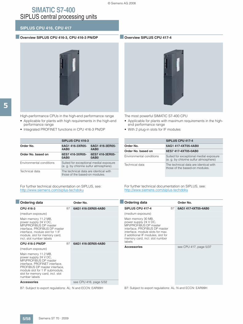
SIMATIC S7-400SIPLUS central processing units
SIPLUS CPU 416, CPU 417
5/58 Siemens ST 70 · 2009
5
■ Overview SIPLUS CPU 416-3, CPU 416-3 PN/DP
High-performance CPUs in the high-end performance range• Applicable for plants with high requirements in the high-end
performance range• Integrated PROFINET functions in CPU 416-3 PN/DP
For further technical documentation on SIPLUS, see:http://www.siemens.com/siplus-techdoku
■ Ordering data Order No.
B7: Subject to export regulations: AL: N and ECCN: EAR99H
■ Overview SIPLUS CPU 417-4
The most powerful SIMATIC S7-400 CPU• Applicable for plants with maximum requirements in the high-
end performance range• With 2 plug-in slots for IF modules
For further technical documentation on SIPLUS, see:http://www.siemens.com/siplus-techdoku
■ Ordering data Order No.
B7: Subject to export regulations: AL: N and ECCN: EAR99H
SIPLUS CPU 416-3
Order No. 6AG1 416-3XR05-4AB0
6AG1 416-3ER05-4AB0
Order No. based on 6ES7 416-3XR05-0AB0
6ES7 416-3ER05-0AB0
Environmental conditions Suited for exceptional medial exposure (e. g. by chlorine sulfur atmosphere).
Technical data The technical data are identical with those of the based-on modules.
CPU 416-3 B7 6AG1 416-3XR05-4AB0
(medium exposure)
Main memory 11.2 MB, power supply 24 V DC, MPI/PROFIBUS DP master interface, PROFIBUS DP master interface, module slot for 1 IF module, slot for memory card, incl. slot number labels
CPU 416-3 PN/DP B7 6AG1 416-3ER05-4AB0
(medium exposure)
Main memory 11.2 MB, power supply 24 V DC, MPI/PROFIBUS DP master interface, PROFINET interface, PROFIBUS DP master interface, module slot for 1 IF submodule, slot for memory card, incl. slot number labels
Accessories see CPU 416, page 5/32
SIPLUS CPU 417-4
Order No. 6AG1 417-4XT05-4AB0
Order No. based on 6ES7 417-4XT05-0AB0
Environmental conditions Suited for exceptional medial exposure (e. g. by chlorine sulfur atmosphere)
Technical data The technical data are identical with those of the based-on modules.
SIPLUS CPU 417-4 B7 6AG1 417-4XT05-4AB0
(medium exposure)
Main memory 30 MB, power supply 24 V DC, MPI/PROFIBUS DP master interface, PROFIBUS DP master interface, module slots for max. 2 additional IF modules, slot for memory card, incl. slot number labels
Accessories see CPU 417, page 5/37
© Siemens AG 2008

SIMATIC S7-400SIPLUS central processing units
SIPLUS CPU 414-4H, CPU 417-4H
5/59Siemens ST 70 · 2009
5
■ Overview SIPLUS CPU 414-4H
CPU for SIMATIC S7-400H and S7-400F/FH• For use in S7-400H fault-tolerant systems• Can be used with F-Runtime license as fail-safe CPU in safety-
related S7-400F/FH systems• With integral PROFIBUS DP master interface• With 2 plug-in slots for sync modules
For further technical documentation on SIPLUS, see:http://www.siemens.com/siplus-techdoku
■ Overview SIPLUS CPU 417-4H
CPU for SIMATIC S7-400H and S7-400F/FH• For use in S7-400H fault-tolerant systems• Can be used with F-Runtime license as fail-safe CPU in safety-
related S7-400F/FH systems• With integral PROFIBUS DP master interface• With 2 plug-in slots for sync modules
For further technical documentation on SIPLUS, see:http://www.siemens.com/siplus-techdoku
■ Technical specifications
SIPLUS CPU 414-4H
Order No. 6AG1 414-4HJ04-4AB0
Order No. based on 6ES7 414-4HJ04-0AB0
Environmental conditions Suited for exceptional medial exposure (e. g. by chlorine sulfur atmosphere)
Technical data The technical data are identical with those of the based-on modules.
SIPLUS CPU 417-4H
Order No. 6AG1 417-4HL04-4AB0
Order No. based on 6ES7 417-4HL04-0AB0
Environmental conditions Suited for exceptional medial exposure (e. g. by chlorine sulfur atmosphere)
Technical data The technical data are identical with those of the based-on modules.
6AG1 414-4HJ04-4AB0
6AG1 417-4HL04-4AB0
Supply voltages
Rated value
• DC 24 V Yes Yes
Feeding of external buffer voltage to CPU
5 to 15 V DC 5 to 15 V DC
Current consumption
from backplane bus DC 5 V, max.
2 A 1.7 A
Current consumption/power loss Power loss, typ. 4.5 W 6 W
Backup battery
• Buffer current, typ. 550 μA 600 μA
• Buffer current, max. 1 530 μA 1 810 μA
6AG1 414-4HJ04-4AB0
6AG1 417-4HL04-4AB0
Memory
Type of storage
RAM
• integrated (for program) 700 Kibyte
• integrated (for data) 700 Kibyte
• expandable No No
Load memory
• expandable FEPROM Yes; with Memory Card (FLASH)
Yes; with Memory Card (FLASH)
• expandable FEPROM, max.
64 MByte 64 MByte
• integrated RAM, max. 256 Kibyte 256 Kibyte
• expandable RAM Yes; With Memory Card (RAM)
Yes; With Memory Card (RAM)
• expandable RAM, max. 16 MByte 16 MByte
© Siemens AG 2008
SIMATIC S7-400SIPLUS central processing units
SIPLUS CPU 414-4H, CPU 417-4H
5/60 Siemens ST 70 · 2009
5
■ Technical specifications (continued)
6AG1 414-4HJ04-4AB0
6AG1 417-4HL04-4AB0
Backup
• present Yes Yes
• with battery Yes; All data Yes; All data
• without battery No No
CPU/blocks
DB
• Number, max. 4 095; DB 0 reserved
8 192; DB 0 reserved
• Size, max. 64 Kibyte
FB
• Number, max. 2 048 6 144
• Size, max. 64 Kibyte 64 Kibyte
FC
• Number, max. 2 048 6 144
• Size, max. 64 Kibyte 64 Kibyte
OB
• Size, max. 64 Kibyte 64 Kibyte
Nesting depth
• per priority class 24 24
• additional within an error OB
2
CPU/processing times
for bit operations, min. 0.06 μs 0.03 μs
for word operations, min. 0.06 μs 0.03 μs
for fixed point arithmetic, min.
0.06 μs 0.03 μs
for floating point arithmetic, min.
0.18 μs 0.09 μs
Times/counters and their remanence
S7 counter
• Number 2 048 2 048
• Remanence- adjustable Yes Yes- lower limit 0 0- upper limit 2 047 2 047- preset From Z 0 to Z 7 From Z 0 to Z 7
• Counting range- lower limit 0 1- upper limit 999 999
IEC counter
• present Yes Yes
• Type SFB SFB
S7 times
• Number 2 048 2 048
• Time range- lower limit 10 ms 10 ms- upper limit 9 990 s 9 990 s
IEC timer
• present Yes Yes
• Type SFB SFB
6AG1 414-4HJ04-4AB0
6AG1 417-4HL04-4AB0
Data areas and their remanence
Flag
• Number, max. 8 Kibyte 16 Kibyte
• Remanence available Yes; MB 0 to MB 8191
Yes; MB 0 to MB 16383
Address area
I/O address area
• Inputs 8 Kibyte 16 Kibyte
• Outputs 8 Kibyte 16 Kibyte
• of which, distributed- MPI/DPinterface, inputs 2 Kibyte 2 Kibyte- MPI/DP interface,
outputs2 Kibyte 2 Kibyte
- DP interface, inputs 6 Kibyte 8 Kibyte- DP interface, outputs 6 Kibyte 8 Kibyte
Process image
• Inputs, adjustable 8 Kibyte 16 Kibyte
• Outputs, adjustable 8 Kibyte 16 Kibyte
• Inputs, preset 1 024 byte 1 024 byte
• Outputs, preset 1 024 byte 1 024 byte
Subprocess images
• Number of subprocess images, max.
8 8
Digital channels
• Inputs 65 536 131 072
• Outputs 65 536 131 072
• Inputs, of which central 65 536 131 072
• Outputs, of which central 65 536 131 072
Analog channels
• Inputs 4 096 8 192
• Outputs 4 096 8 192
• Inputs, of which central 4 096 8 192
• Outputs, of which central 4 096 8 192
Hardware config.
Central devices, max. 1 1
Expansion devices, max. 21 21
Multicomputing No No
IM
• Number of connectable IMs (total), max.
6 6
• Number of connectable IM 460s, max.
6 6
• Number of connectable IM 463s, max.
6; IM 463-2 6; IM 463-2
© Siemens AG 2008

SIMATIC S7-400SIPLUS central processing units
SIPLUS CPU 414-4H, CPU 417-4H
5/61Siemens ST 70 · 2009
5
■ Technical specifications (continued)
6AG1 414-4HJ04-4AB0
6AG1 417-4HL04-4AB0
Number of DP masters
• integrated 2 2
• via IM 467 0 0
• via CP 10 10
• Mixed mode IM + CP permitted
No; IM 467 cannot be used jointly with CP 443-5 Ext.
No; IM 467 cannot be used jointly with CP 443-5 Ext.
• via interface module 0 0
Number of operable FMs and CPs (recommended)
• FM 32; Limited due to number of slots and number of connec-tions
64; Limited due to number of slots and number of connec-tions
• CP, point-to-point 32; Limited due to number of slots and number of connec-tions
64; Limited due to number of slots and number of connec-tions
• CP, LAN 32; limited due to number of slots and number of connec-tions
64; limited due to number of slots and number of connec-tions
Time
Clock
• Hardware clock (real-time clock)
Yes Yes
• buffered and synchroni-zable
Yes Yes
Operating hours counter
• Number 8 8
Clock synchronization
• supports Yes Yes
S7 message functions
Number of login stations for message functions, max.
8 16
Diagnostic buffer
• present Yes
• Number of entries, max. 3 200
• adjustable Yes
• preset 120
Communication functions
PG/OP communication Yes Yes
Global data communication
• supported No No
S7 basic communication
• supported No No
S7 communication
• supported Yes Yes
• as server Yes Yes
• as client Yes Yes
• Useful data per job, max. 64 Kibyte 64 Kibyte
6AG1 414-4HJ04-4AB0
6AG1 417-4HL04-4AB0
S5-compatible communi-cation
• supported Yes; via CP and loadable FC
Yes; via CP and loadable FC
• Useful data per job, max. 8 Kibyte 8 Kibyte
Standard communication (FMS)
• supported Yes; Via CP and loadable FB
Yes; Via CP and loadable FB
• Useful data per job, max. Dependent on CP Dependent on CP
Number of connections
• overall 32 64
1st interface
Physics RS 485 / PROFIBUS RS 485 / PROFIBUS
isolated Yes Yes
Functionality
• MPI Yes; Default setting Yes; Default setting
• DP master Yes Yes
• DP slave No No
MPI
• Number of connections 32 44
• Services- PG/OP communication Yes Yes- Global data communi-
cationNo No
- S7 basic communication No No- S7 communication Yes Yes
• Transmission speeds, max.
12 MBit/s 12 MBit/s
DP master
• Number of connections, max.
32 32
• Services- PG/OP communication Yes Yes- Global data communi-
cationNo No
- S7 basic communication No No- S7 communication No No- S7 communication, as
clientNo No
- S7 communication, as server
No No
- equidistance support No No- Activation/deactivation of
DP slavesYes No
- direct data exchange (cross traffic)
No No
• Transmission speeds, max.
12 MBit/s 12 MBit/s
• Number of DP slaves, max. 32; Number of slots, max. 512
32; Number of slots, max. 512
© Siemens AG 2008

SIMATIC S7-400SIPLUS central processing units
SIPLUS CPU 414-4H, CPU 417-4H
5/62 Siemens ST 70 · 2009
5
■ Technical specifications (continued)
■ Ordering data Order No. Order No.
6AG1 414-4HJ04-4AB0
6AG1 417-4HL04-4AB0
DP master (continued)
• Address area- Inputs, max. 2 Kibyte 2 Kibyte- Outputs, max. 2 Kibyte 2 Kibyte
• Useful data per DP slave- Inputs, max. 244 byte 244 byte- Outputs, max. 244 byte 244 byte
2nd interface
Physics RS 485 / PROFIBUS RS 485 / PROFIBUS
isolated Yes Yes
Functionality
• DP master Yes; Default setting Yes
• DP slave No No
• Point-to-point coupling No No
DP master
• Number of connections, max.
16 32
• Number of connections (of which reserved), max.
1 for PG, 1 for OP 1 for PG, 1 for OP
• Services- PG/OP communication Yes Yes- S7 basic communication No No- S7 communication No No- S7 communication, as
clientNo No
- S7 communication, as server
No No
- equidistance support No No- Activation/deactivation of
DP slavesNo No
- direct data exchange (cross traffic)
No No
• Transmission speeds, max.
12 MBit/s 12 MBit/s
• Number of DP slaves, max. 96 125; Number of slots, max. 2048
• Address area- Inputs, max. 8 Kibyte 8 Kibyte- Outputs, max. 8 Kibyte 8 Kibyte
• Useful data per DP slave- Inputs, max. 244 byte 244 byte- Outputs, max. 244 byte 244 byte
6AG1 414-4HJ04-4AB0
6AG1 417-4HL04-4AB0
CPU/programming
Programming language
• STEP 7 Yes; V5.0 SP2 Yes; V5.0 SP2
• LAD Yes Yes
• FUP Yes Yes
• AWL Yes Yes
• SCL Yes Yes
• CFC Yes Yes
• GRAPH Yes Yes
• HiGraph Yes Yes
User program protection/password protection
Yes Yes
Dimensions
Required slots 2 2
Dimensions Dimensions
• Width 50 mm 50 mm
• Height 290 mm 290 mm
• Depth 219 mm 219 mm
Weights
• Weight, approx. 1 070 g 1 070 g
SIPLUS CPU 414-4H(medium exposure)
6AG1 414-4HJ04-4AB0
For S7-400H and S7-400F/FH;main memory 1.4 MB, MPI/PROFIBUS DP master interface, 2 slots for synchroni-zation modules, slot for memory card, incl. slot number plates
SIPLUS CPU 417-4H(medium exposure)
6AG1 417-4HL04-4AB0
For S7-400H and S7-400F/FH;main memory 20 MB, MPI/PROFIBUS DP master interface, 2 slots for synchroni-zation modules, slot for memory card, incl. slot number plates
Accessories see CPU 41xH, page 5/46
© Siemens AG 2008
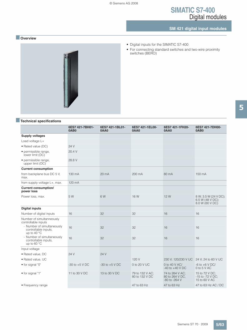
SIMATIC S7-400Digital modules
SM 421 digital input modules
5/63Siemens ST 70 · 2009
5
■ Overview
• Digital inputs for the SIMATIC S7-400• For connecting standard switches and two-wire proximity
switches (BERO)
■ Technical specifications
6ES7 421-7BH01-0AB0
6ES7 421-1BL01-0AA0
6ES7 421-1EL00-0AA0
6ES7 421-1FH20-0AA0
6ES7 421-7DH00-0AB0
Supply voltages
Load voltage L+
• Rated value (DC) 24 V
• permissible range, lower limit (DC)
20.4 V
• permissible range, upper limit (DC)
28.8 V
Current consumption
from backplane bus DC 5 V, max.
130 mA 20 mA 200 mA 80 mA 150 mA
from supply voltage L+, max. 120 mA
Current consumption/power loss
Power loss, max. 5 W 6 W 16 W 12 W 8 W; 3.5 W (24 V DC); 6.5 W (48 V DC); 8.0 W (60 V DC)
Digital inputs
Number of digital inputs 16 32 32 16 16
Number of simultanneously controllable inputs
- Number of simultaneously controllable inputs, up to 40 °C
16 32 32 16 16
- Number of simultaneously controllable inputs, up to 60 °C
16 32 32 16 16
Input voltage
• Rated value, DC 24 V 24 V
• Rated value, UC 120 V 230 V; 120/230 V UC 24 V; 24 to 60 V UC
• for signal "0" -30 to +5 V DC -30 to +5 V DC 0 to 20 V UC 0 to 40 V AC/ -40 to +40 V DC
-6 to +6 V DC/ 0 to 5 V AC
• for signal "1" 11 to 30 V DC 13 to 30 V DC 79 to 132 V AC; 80 to 132 V DC
74 to 264 V AC; 80 to 264 V DC, -80 to -264 V
15 to 72 V DC; -15 to -72 V DC; 15 to 60 V AC
• Frequency range 47 to 63 Hz 47 to 63 Hz 47 to 63 Hz AC / DC
© Siemens AG 2008
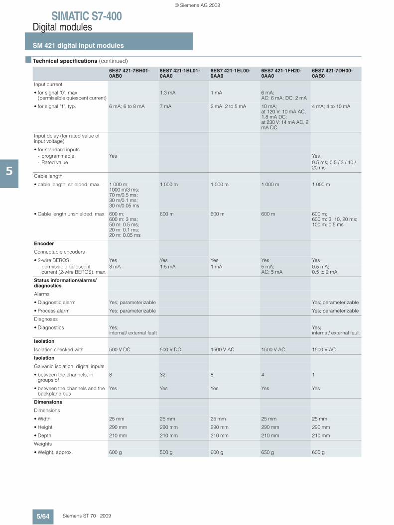
SIMATIC S7-400Digital modules
SM 421 digital input modules
5/64 Siemens ST 70 · 2009
5
■ Technical specifications (continued)
6ES7 421-7BH01-0AB0
6ES7 421-1BL01-0AA0
6ES7 421-1EL00-0AA0
6ES7 421-1FH20-0AA0
6ES7 421-7DH00-0AB0
Input current
• for signal "0", max. (permissible quiescent current)
1.3 mA 1 mA 6 mA;AC: 6 mA; DC: 2 mA
• for signal "1", typ. 6 mA; 6 to 8 mA 7 mA 2 mA; 2 to 5 mA 10 mA; at 120 V: 10 mA AC, 1.8 mA DC; at 230 V: 14 mA AC, 2 mA DC
4 mA; 4 to 10 mA
Input delay (for rated value of input voltage)
• for standard inputs- programmable Yes Yes- Rated value 0.5 ms; 0.5 / 3 / 10 /
20 ms
Cable length
• cable length, shielded, max. 1 000 m; 1000 m/3 ms; 70 m/0.5 ms; 30 m/0.1 ms; 30 m/0.05 ms
1 000 m 1 000 m 1 000 m 1 000 m
• Cable length unshielded, max. 600 m; 600 m: 3 ms; 50 m: 0.5 ms; 20 m: 0.1 ms; 20 m: 0.05 ms
600 m 600 m 600 m 600 m; 600 m: 3, 10, 20 ms; 100 m: 0.5 ms
Encoder
Connectable encoders
• 2-wire BEROS Yes Yes Yes Yes Yes- permissible quiescent
current (2-wire BEROS), max.3 mA 1.5 mA 1 mA 5 mA;
AC: 5 mA0.5 mA; 0.5 to 2 mA
Status information/alarms/diagnostics
Alarms
• Diagnostic alarm Yes; parameterizable Yes; parameterizable
• Process alarm Yes; parameterizable Yes; parameterizable
Diagnoses
• Diagnostics Yes;internal/ external fault
Yes;internal/ external fault
Isolation
Isolation checked with 500 V DC 500 V DC 1500 V AC 1500 V AC 1500 V AC
Isolation
Galvanic isolation, digital inputs
• between the channels, in groups of
8 32 8 4 1
• between the channels and the backplane bus
Yes Yes Yes Yes Yes
Dimensions
Dimensions
• Width 25 mm 25 mm 25 mm 25 mm 25 mm
• Height 290 mm 290 mm 290 mm 290 mm 290 mm
• Depth 210 mm 210 mm 210 mm 210 mm 210 mm
Weights
• Weight, approx. 600 g 500 g 600 g 650 g 600 g
© Siemens AG 2008
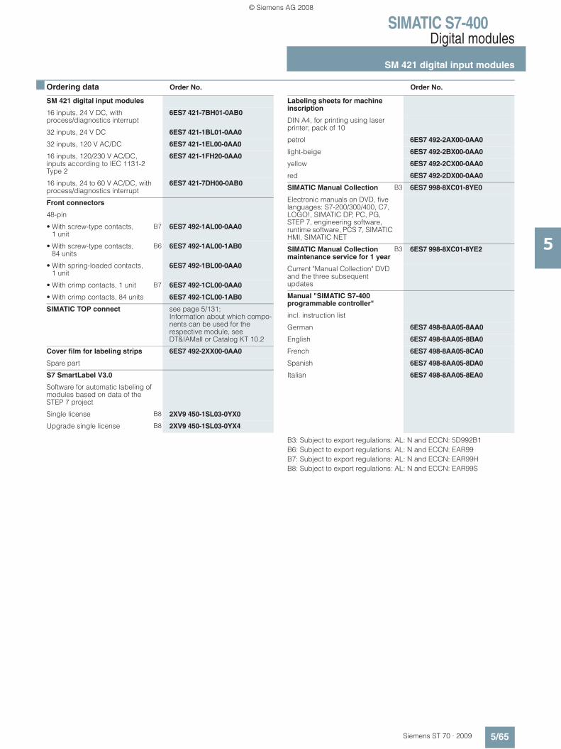
SIMATIC S7-400Digital modules
SM 421 digital input modules
5/65Siemens ST 70 · 2009
5
■ Ordering data Order No. Order No.
B3: Subject to export regulations: AL: N and ECCN: 5D992B1B6: Subject to export regulations: AL: N and ECCN: EAR99B7: Subject to export regulations: AL: N and ECCN: EAR99HB8: Subject to export regulations: AL: N and ECCN: EAR99S
SM 421 digital input modules
16 inputs, 24 V DC, with process/diagnostics interrupt
6ES7 421-7BH01-0AB0
32 inputs, 24 V DC 6ES7 421-1BL01-0AA0
32 inputs, 120 V AC/DC 6ES7 421-1EL00-0AA0
16 inputs, 120/230 V AC/DC, inputs according to IEC 1131-2 Type 2
6ES7 421-1FH20-0AA0
16 inputs, 24 to 60 V AC/DC, with process/diagnostics interrupt
6ES7 421-7DH00-0AB0
Front connectors
48-pin
• With screw-type contacts, 1 unit
B7 6ES7 492-1AL00-0AA0
• With screw-type contacts, 84 units
B6 6ES7 492-1AL00-1AB0
• With spring-loaded contacts, 1 unit
6ES7 492-1BL00-0AA0
• With crimp contacts, 1 unit B7 6ES7 492-1CL00-0AA0
• With crimp contacts, 84 units 6ES7 492-1CL00-1AB0
SIMATIC TOP connect see page 5/131;Information about which compo-nents can be used for the respective module, see DT&IAMall or Catalog KT 10.2
Cover film for labeling strips 6ES7 492-2XX00-0AA0
Spare part
S7 SmartLabel V3.0
Software for automatic labeling of modules based on data of the STEP 7 project
Single license B8 2XV9 450-1SL03-0YX0
Upgrade single license B8 2XV9 450-1SL03-0YX4
Labeling sheets for machine inscription
DIN A4, for printing using laser printer; pack of 10
petrol 6ES7 492-2AX00-0AA0
light-beige 6ES7 492-2BX00-0AA0
yellow 6ES7 492-2CX00-0AA0
red 6ES7 492-2DX00-0AA0
SIMATIC Manual Collection B3 6ES7 998-8XC01-8YE0
Electronic manuals on DVD, five languages: S7-200/300/400, C7, LOGO!, SIMATIC DP, PC, PG, STEP 7, engineering software, runtime software, PCS 7, SIMATIC HMI, SIMATIC NET
SIMATIC Manual Collection maintenance service for 1 year
B3 6ES7 998-8XC01-8YE2
Current "Manual Collection" DVD and the three subsequent updates
Manual "SIMATIC S7-400 programmable controller"
incl. instruction list
German 6ES7 498-8AA05-8AA0
English 6ES7 498-8AA05-8BA0
French 6ES7 498-8AA05-8CA0
Spanish 6ES7 498-8AA05-8DA0
Italian 6ES7 498-8AA05-8EA0
© Siemens AG 2008

SIMATIC S7-400Digital modules
SM 422 digital output modules
5/66 Siemens ST 70 · 2009
5
■ Overview
• Digital outputs for the SIMATIC S7-400• For connecting solenoid valves, contactors, low-power
motors, lamps and motor starters
■ Technical specifications
6ES7 422-1FH00-0AA0
6ES7 422-1HH00-0AA0
6ES7 422-1BH11-0AA0
6ES7 422-1BL00-0AA0
6ES7 422-7BL00-0AB0
Supply voltages
Load voltage L+
• Rated value (DC) 60 V 24 V 24 V 24 V
• permissible range, lower limit (DC)
1 V 20.4 V 20.4 V 20.4 V
• permissible range, upper limit (DC)
60 V 28.8 V 28.8 V 28.8 V
Load voltage L1
• Rated value (AC) 230 V; 120/230 V AC 230 V
• permissible range, lower limit (AC)
79 V 2 V 20.4 V
• permissible range, upper limit (AC)
264 V 264 V 28.8 V
Current consumption
from load voltage L+ (without load), max.
1.5 mA 30 mA 30 mA 120 mA
from load voltage L1 (without load), max.
6 mA
from backplane bus DC 5 V, max.
400 mA 1 A 160 mA 200 mA 200 mA
Current consumption/power loss Power loss, max. 16 W 25 W 7 W 4 W 8 W
Digital outputs
Number of digital outputs 16 16; Relay 16 32 32
Short-circuit protection of the output
Yes; Fuse 8 A, 250 V; per group
Yes; clocked electronically
Yes; clocked electronically
Yes; clocked electronically
Limitation of inductive shutdown voltage to
-30 V -27 V L+ (-45 V)
Lamp load, max. 50 W 60 W 10 W 5 W 5 W
Output voltage
• for signal "1", min. L1 (-18.1 V) L+ (-0.5 V) L+ (-0.3 V) L+ (-0.8 V)
© Siemens AG 2008
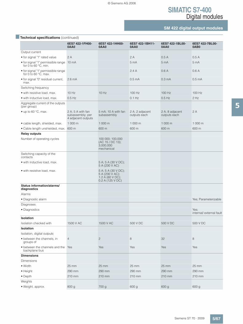
SIMATIC S7-400Digital modules
SM 422 digital output modules
5/67Siemens ST 70 · 2009
5
■ Technical specifications (continued)
6ES7 422-1FH00-0AA0
6ES7 422-1HH00-0AA0
6ES7 422-1BH11-0AA0
6ES7 422-1BL00-0AA0
6ES7 422-7BL00-0AB0
Output current
• for signal "1" rated value 2 A 2 A 0.5 A 0.5 A
• for signal "1" permissible range for 0 to 60 °C, min.
10 mA 5 mA 5 mA 5 mA
• for signal "1" permissible range for 0 to 60 °C, max.
2.4 A 0.6 A 0.6 A
• for signal "0" residual current, max.
2.6 mA 0.5 mA 0.3 mA 0.5 mA
Switching frequency
• with resistive load, max. 10 Hz 10 Hz 100 Hz 100 Hz 100 Hz
• with inductive load, max. 0.5 Hz 0.1 Hz 0.5 Hz 2 Hz
Aggregate current of the outputs (per group)
• up to 60 °C, max. 2 A; 5 A with fan subassembly; per 4 adjacent outputs
5 mA; 10 A with fan subassembly
2 A; 2 adjacent outputs each
2 A; 8 adjacent outputs each
2 A
• cable length, shielded, max. 1 000 m 1 000 m 1 000 m 1 000 m 1 000 m
• Cable length unshielded, max. 600 m 600 m 600 m 600 m 600 m
Relay outputs
Number of operating cycles 100 000; 100,000 (AC 15 / DC 13); 3,000,000 mechanical
Switching capacity of the contacts
• with inductive load, max. 5 A; 5 A (30 V DC); 5 A (230 V AC)
• with resistive load, max. 5 A; 5 A (30 V DC); 5 A (230 V AC); 1.2 A (60 V DC); 0.2 A (125 V DC)
Status information/alarms/diagnostics
Alarms
• Diagnostic alarm Yes; Parameterizable
Diagnoses
• Diagnostics Yes; internal/ external fault
Isolation
Isolation checked with 1500 V AC 1500 V AC 500 V DC 500 V DC 500 V DC
Isolation
Isolation, digital outputs
• between the channels, in groups of
4 2 8 32 8
• between the channels and the backplane bus
Yes Yes Yes Yes Yes
Dimensions
Dimensions
• Width 25 mm 25 mm 25 mm 25 mm 25 mm
• Height 290 mm 290 mm 290 mm 290 mm 290 mm
• Depth 210 mm 210 mm 210 mm 210 mm 210 mm
Weights
• Weight, approx. 800 g 700 g 600 g 600 g 600 g
© Siemens AG 2008
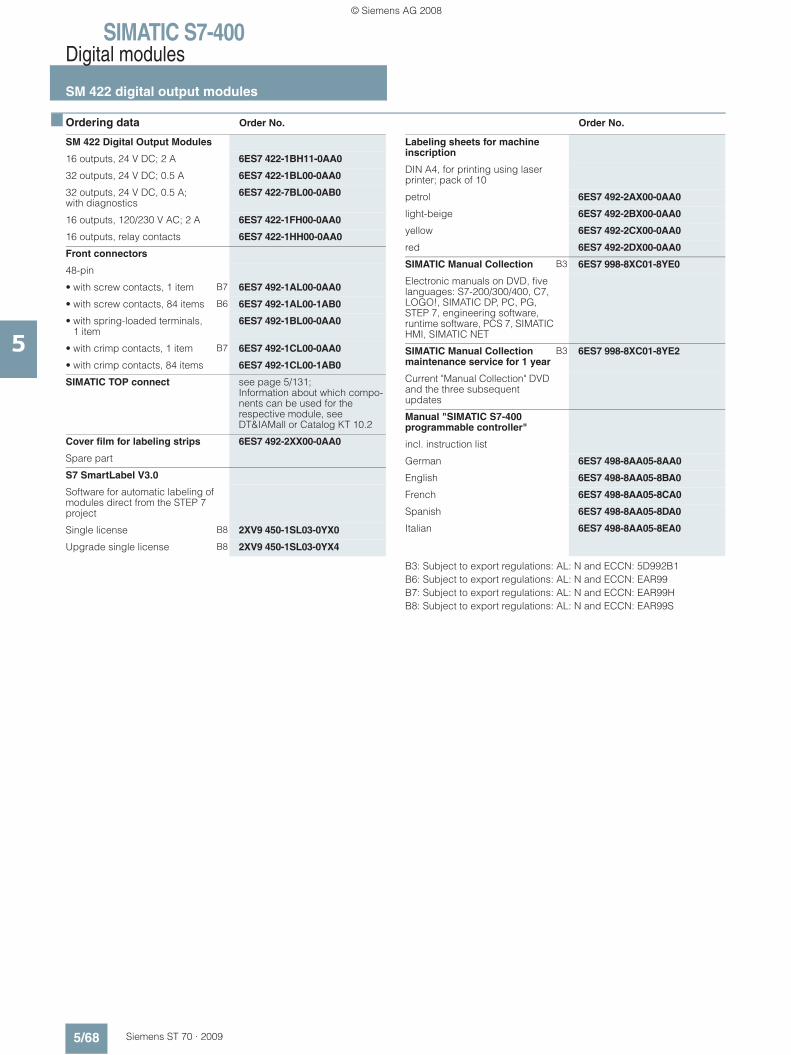
SIMATIC S7-400Digital modules
SM 422 digital output modules
5/68 Siemens ST 70 · 2009
5
■ Ordering data Order No. Order No.
B3: Subject to export regulations: AL: N and ECCN: 5D992B1B6: Subject to export regulations: AL: N and ECCN: EAR99B7: Subject to export regulations: AL: N and ECCN: EAR99HB8: Subject to export regulations: AL: N and ECCN: EAR99S
SM 422 Digital Output Modules
16 outputs, 24 V DC; 2 A 6ES7 422-1BH11-0AA0
32 outputs, 24 V DC; 0.5 A 6ES7 422-1BL00-0AA0
32 outputs, 24 V DC, 0.5 A; with diagnostics
6ES7 422-7BL00-0AB0
16 outputs, 120/230 V AC; 2 A 6ES7 422-1FH00-0AA0
16 outputs, relay contacts 6ES7 422-1HH00-0AA0
Front connectors
48-pin
• with screw contacts, 1 item B7 6ES7 492-1AL00-0AA0
• with screw contacts, 84 items B6 6ES7 492-1AL00-1AB0
• with spring-loaded terminals, 1 item
6ES7 492-1BL00-0AA0
• with crimp contacts, 1 item B7 6ES7 492-1CL00-0AA0
• with crimp contacts, 84 items 6ES7 492-1CL00-1AB0
SIMATIC TOP connect see page 5/131;Information about which compo-nents can be used for the respective module, see DT&IAMall or Catalog KT 10.2
Cover film for labeling strips 6ES7 492-2XX00-0AA0
Spare part
S7 SmartLabel V3.0
Software for automatic labeling of modules direct from the STEP 7 project
Single license B8 2XV9 450-1SL03-0YX0
Upgrade single license B8 2XV9 450-1SL03-0YX4
Labeling sheets for machine inscription
DIN A4, for printing using laser printer; pack of 10
petrol 6ES7 492-2AX00-0AA0
light-beige 6ES7 492-2BX00-0AA0
yellow 6ES7 492-2CX00-0AA0
red 6ES7 492-2DX00-0AA0
SIMATIC Manual Collection B3 6ES7 998-8XC01-8YE0
Electronic manuals on DVD, five languages: S7-200/300/400, C7, LOGO!, SIMATIC DP, PC, PG, STEP 7, engineering software, runtime software, PCS 7, SIMATIC HMI, SIMATIC NET
SIMATIC Manual Collection maintenance service for 1 year
B3 6ES7 998-8XC01-8YE2
Current "Manual Collection" DVD and the three subsequent updates
Manual "SIMATIC S7-400 programmable controller"
incl. instruction list
German 6ES7 498-8AA05-8AA0
English 6ES7 498-8AA05-8BA0
French 6ES7 498-8AA05-8CA0
Spanish 6ES7 498-8AA05-8DA0
Italian 6ES7 498-8AA05-8EA0
© Siemens AG 2008

SIMATIC S7-400SIPLUS digital modules
SIPLUS SM 421 digital input modulesSIPLUS SM 422 digital output modules
5/69Siemens ST 70 · 2009
5
■ Overview SIPLUS SM 421
• Digital inputs for SIMATIC S7-400• For connection of switches and 2-wire proximity switches
(BEROs)
For further technical documentation on SIPLUS, see:http://www.siemens.com/siplus-techdoku
■ Ordering data Order No.
■ Overview SIPLUS SM 422
• Digital outputs for SIMATIC S7-400• For connecting solenoid valves, contactors, small-power
motors, lamps and motor starters
For further technical documentation on SIPLUS, see:http://www.siemens.com/siplus-techdoku
■ Ordering data Order No.
Digital input module SIPLUS SM 421
Order No. 6AG1 421-1BL01-2AA0
Order No. based on 6ES7 421-1BL01-0AA0
Ambient temperature range -25 ... +60 °C
Environmental conditions Suited for exceptional medial exposure (e. g. by chlorine sulfur atmosphere).
Technical data The technical data are identical with those of the based-on modules.
SIPLUS SM 421 digital input module
(extended temperature range and medium exposure)
32 inputs, 24 V DC 6AG1 421-1BL01-2AA0
Accessories see S7-400 digital input modules SM 421, page 5/65
Digital input module SIPLUS SM 422
Order No. 6AG1 422-1BL00-2AA0
Order No. based on 6ES7 422-1BL00-0AA0
Ambient temperature range -25 ... +60 °C
Environmental conditions Suited for exceptional medial exposure (e. g. by chlorine sulfur atmosphere).
Technical data The technical data are identical with those of the based-on modules.
SIPLUS SM 422 digital output module
(extended temperature range and medium exposure)
32 outputs, 24 V DC; 0.5 A 6AG1 422-1BL00-2AA0
Accessories see S7-400 digital output modules SM 422, page 5/68
© Siemens AG 2008

SIMATIC S7-400Analog modules
SM 431 analog input modules
5/70 Siemens ST 70 · 2009
5
■ Overview
• Analog inputs for the SIMATIC S7-400• For connection of voltage and current sensors,
thermocouples, resistors and resistance thermometers• Resolution from 13 to 16 bit
■ Technical specifications
6ES7 431-0HH00-0AB0 6ES7 431-1KF20-0AB0 6ES7 431-1KF00-0AB0 6ES7 431-1KF10-0AB0
Supply voltages
Load voltage L+
• Rated value (DC) 24 V; only required for supplying 2-wire trans-mitters
24 V; only required for supplying 2-wire trans-mitters
not necessary 24 V; only required for supplying 2-wire trans-mitters
• reverse polarity protection Yes Yes Yes
Current consumption
from load voltage L+ (without load), max.
400 mA; for 16 connected, fully controlled 2-wire trans-mitters
200 mA; for 8 connected, fully controlled 2-wire trans-mitters
200 mA
from backplane bus DC 5 V, max.
100 mA 1 000 mA 350 mA 600 mA
Current consumption/power loss
Power loss, typ. 2 W 4.9 W 1.8 W 3.5 W
Analog inputs
Number of analog inputs 16 8 8 8
Number of analog inputs for voltage/current measurement
16 8 8 8
Number of analog inputs for resistance measurement
4 4 4
cable length, shielded, max. 200 m 200 m 200 m 200 m; 50 m with thermo-couples and input ranges <= 80 mV
Input ranges (rated values), voltages
• 1 to 5 V Yes Yes Yes Yes
• -1 V to +1 V Yes Yes Yes Yes
• -10 V to +10 V Yes Yes Yes Yes
• -2.5 V to +2.5 V Yes
• -250 mV to +250 mV Yes
• -5 V to +5 V Yes
• -500 mV to +500 mV Yes
• -80 mV to +80 mV Yes
© Siemens AG 2008
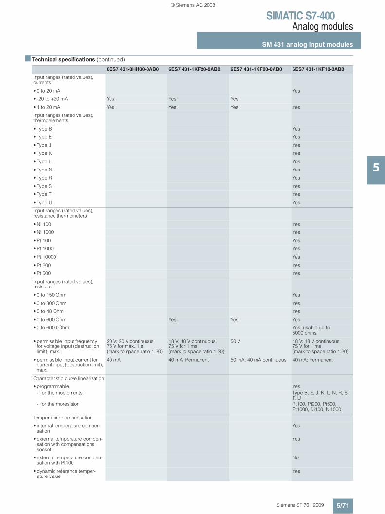
SIMATIC S7-400Analog modules
SM 431 analog input modules
5/71Siemens ST 70 · 2009
5
■ Technical specifications (continued)
6ES7 431-0HH00-0AB0 6ES7 431-1KF20-0AB0 6ES7 431-1KF00-0AB0 6ES7 431-1KF10-0AB0
Input ranges (rated values), currents
• 0 to 20 mA Yes
• -20 to +20 mA Yes Yes Yes
• 4 to 20 mA Yes Yes Yes Yes
Input ranges (rated values), thermoelements
• Type B Yes
• Type E Yes
• Type J Yes
• Type K Yes
• Type L Yes
• Type N Yes
• Type R Yes
• Type S Yes
• Type T Yes
• Type U Yes
Input ranges (rated values), resistance thermometers
• Ni 100 Yes
• Ni 1000 Yes
• Pt 100 Yes
• Pt 1000 Yes
• Pt 10000 Yes
• Pt 200 Yes
• Pt 500 Yes
Input ranges (rated values), resistors
• 0 to 150 Ohm Yes
• 0 to 300 Ohm Yes
• 0 to 48 Ohm Yes
• 0 to 600 Ohm Yes Yes Yes
• 0 to 6000 Ohm Yes; usable up to 5000 ohms
• permissible input frequency for voltage input (destruction limit), max.
20 V; 20 V continuous, 75 V for max. 1 s (mark to space ratio 1:20)
18 V; 18 V continuous, 75 V for 1 ms (mark to space ratio 1:20)
50 V 18 V; 18 V continuous, 75 V for 1 ms (mark to space ratio 1:20)
• permissible input current for current input (destruction limit), max.
40 mA 40 mA; Permanent 50 mA; 40 mA continuous 40 mA; Permanent
Characteristic curve linearization
• programmable Yes- for thermoelements Type B, E, J, K, L, N, R, S,
T, U- for thermoresistor Pt100, Pt200, Pt500,
Pt1000, Ni100, Ni1000
Temperature compensation
• internal temperature compen-sation
Yes
• external temperature compen-sation with compensations socket
Yes
• external temperature compen-sation with Pt100
No
• dynamic reference temper-ature value
Yes
© Siemens AG 2008

SIMATIC S7-400Analog modules
SM 431 analog input modules
5/72 Siemens ST 70 · 2009
5
■ Technical specifications (continued)
6ES7 431-0HH00-0AB0 6ES7 431-1KF20-0AB0 6ES7 431-1KF00-0AB0 6ES7 431-1KF10-0AB0
Analog value creation
Integration and conversion time/resolution per channel
• Resolution with overload area (bit including sign), max.
13 Bit 14 Bit; 14 / 14 / 14 13 Bit 14 Bit; with activated smoothing: 16 Bit
• Integration time, parameterizable
Yes Yes Yes Yes
• Basic conversion time, ms 50 / 60 ms 16.7 / 20 ms 16.7 / 20 ms
• Integration time, ms 55 / 65 ms 52 μs 23 / 25 ms 20.1 / 23.5 ms
• additional conversion time for wire break monitoring
4.3 ms
• additional conversiontime for resistance measurement
5.5 ms
• additional conversiontime for wire break monitoring and resistance measurement
40.2 / 47 ms
• Interference voltage suppression for interference frequency f1 in Hz
60 / 50 Hz none / 400 / 60 / 50 Hz 60 / 50 Hz 60 / 50 Hz
Encoder
Connection of signal encoders
• for current measurement as 2-wire transducer
Yes Yes; with external trans-mitter supply
Yes
• for current measurement as 4-wire transducer
Yes Yes Yes Yes
• for resistance measurement with 2-conductor connection
Yes; Line resistances are also measured
Yes; Line resistances are also measured
Yes; Line resistances are also measured
• for resistance measurement with 3-conductor connection
Yes; Line resistances are also measured
Yes; Line resistances are also measured
Yes
• for resistance measurement with 4-conductor connection
Yes Yes Yes
Errors/accuracies
Operational limit in overall temperature range
• Voltage, relative to input area +/- 0,65 %; 1.0% at 1 to 5 V; 0.65% at +/-1 V, +/-10 V
+/- 0,7 %; +/-0.7% at +/-1 V; +/-0.9% at +/-10 V, 1 to 5 V
+/- 1 %; +/-1.0% at +/-1 V; +/-0.6% at +/-10 V; +/-0.7% at 1 to 5 V
+/- 0,38 %; +/-0.38% at +/-80 mV; +/-0.35% at +/-250 mV, +/-500mV, +/-1 V, +/-2,5 V, +/-5 V, 1 to 5 V, +/-10 V
• Current, relative to input area +/- 0.65 % +/- 0,8 %; at +/-20 mA, 4 to 20 mA
+/- 1 %; at +/-20 mA, 4 to 20 mA
+/- 0,35 %; 0 to 20 mA, +/-20 mA, 4 to 20 mA
• Impedance, relative to input area
+/- 1 % +/- 1,25 %; 0 to 500 ohms (4-conductor measurement, in range of 600 ohms)
+/- 0.5 %
• Resistance-type thermometer, relative to input area
+/- 0.5 %
Basic error limit (operational limit at 25 °C)
• Voltage, relative to input area +/- 0,25 %; 0.5% at 1 to 5 V; 0.25% at +/-1 V, +/-10 V
+/- 0,6 %; 0.6% at +/-1 V; 0.75% at +/-10 V, 1 to 5 V
+/- 0,7 %; 0.7% at +/-1 V; 0.4% at +/-10 V; 0.5% at 1 to 5 V
+/- 0,15 %; +/-0.15% (+/-250 mV, +/-500 mV, +/-1 V, +/-2.5 V, +/-5 V, 1 to 5 V, +/- 10 V); +/-0.17% (+/- 80 mV);
• Current, relative to input area +/- 0,25 %; at +/-20 mA, 4 to 20 mA
+/- 0,7 %; at +/- 20 mA, 4...20 mA
+/- 0,7 %; at +/- 20 mA, 4...20 mA
+/- 0,15 %; 0 to 20 mA, +/- 20 mA, 4 to 20 mA
© Siemens AG 2008

SIMATIC S7-400Analog modules
SM 431 analog input modules
5/73Siemens ST 70 · 2009
5
■ Technical specifications (continued)
6ES7 431-0HH00-0AB0 6ES7 431-1KF20-0AB0 6ES7 431-1KF00-0AB0 6ES7 431-1KF10-0AB0
Basic error limit (operational limit at 25 °C)
• Impedance, relative to input area
+/- 0,7 %; 0 to 600 ohms +/- 0,8 %; 0 to 500 ohms (4-conductor measurement, in range of 600 ohms)
+/- 0,15 %; +/-0.15% at 0 to 48 ohms (4-conductor measurement), 0 to 150 ohms (4-conductor measurement), 0 to 300 ohms (4-conductor measurement), 0 to 600 ohms (4-conductor measurement), 0 to 5000 ohms (4-conductor measurement, in range of 6000 ohms); +/-0.3% at 0 to 300 ohms (3-conductor measurement), 0 to 600 ohms (3-conductor measurement), 0 to 5000 ohms (3-conductor measurement, in range of 6000 ohms)
• Resistance-type thermometer, relative to input area
+/- 0.3 %
Isolation
Isolation checked with 500 V DC between bus and local ground
2120 V DC between bus and analog part; 500 V DC between bus and local ground; 707 V DC between analog part and L+/M; 2120 V DC between analog part and local ground; 2120 V DC between L+/M and local ground
2120 V DC between bus and analog part; 500 V DC between bus and local ground; 2120 V DC between analog part and local ground
2120 V DC between bus and L+/M; 2120 V D between bus and analog part; 500 V DC between bus and local ground; 707 V DC between analog part and L+/M; 2120 V DC between analog part and local ground; 2120 V DC between L+/M and local ground
Isolation
Isolation, analog inputs
• Isolation, analog inputs No Yes; internal/external Yes; internal/external Yes; internal/external
• between the channels No No No No
Permissible potential difference
between the inputs (UCM) 2 V DC / 2 Vpp AC 8 V AC 30 V AC 120 V AC
Dimensions
Required slots 1 1 1 1
Dimensions
Dimensions
• Width 25 mm 25 mm 25 mm 25 mm
• Height 290 mm 290 mm 290 mm 290 mm
• Depth 210 mm 210 mm 210 mm 210 mm
Weights
• Weight, approx. 500 g 500 g 500 g 500 g
© Siemens AG 2008

SIMATIC S7-400Analog modules
SM 431 analog input modules
5/74 Siemens ST 70 · 2009
5
■ Technical specifications (continued)
6ES7 431-7QH00-0AB0 6ES7 431-7KF00-0AB0 6ES7 431-7KF10-0AB0
Supply voltages
Load voltage L+
• Rated value (DC) 24 V; only required for supplying 2-wire transmitters
• reverse polarity protection Yes
Current consumption
from load voltage L+ (without load), max.
400 mA 400 mA 400 mA
from backplane bus DC 5 V, max.
700 mA 1 200 mA 650 mA
Current consumption/power loss
Power loss, typ. 4.5 W 4.6 W 3.3 W
Analog inputs
Number of analog inputs 16 8 8
Number of analog inputs for voltage/current measurement
16 8
Number of analog inputs for resistance measurement
8 8
cable length, shielded, max. 200 m; 50 m with thermocouples and input ranges <= 80 mV
200 m 200 m; 50 m with thermocouples and input ranges +/-80 mV
Input ranges (rated values), voltages
• 1 to 5 V Yes Yes
• -1 V to +1 V Yes Yes
• -10 V to +10 V Yes Yes
• -100 mV to +100 mV Yes
• -2.5 V to +2.5 V Yes Yes
• -20 mV to +20 mV Yes
• -25 mV to +25 mV Yes
• -250 mV to +250 mV Yes Yes
• -5 V to +5 V Yes Yes
• -50 mV to +50 mV Yes Yes
• -500 mV to +500 mV Yes Yes
• -80 mV to +80 mV Yes Yes
Input ranges (rated values), currents
• 0 to 20 mA Yes Yes
• -10 to +10 mA Yes Yes
• -20 to +20 mA Yes Yes
• -3.2 to +3.2 mA Yes
• 4 to 20 mA Yes Yes
• -5 to +5 mA Yes Yes
Input ranges (rated values), thermoelements
• Type B Yes Yes
• Type E Yes Yes
• Type J Yes Yes
• Type K Yes Yes
• Type L Yes Yes
• Type N Yes Yes
• Type R Yes Yes
• Type S Yes Yes
• Type T Yes Yes
• Type U Yes Yes
© Siemens AG 2008

SIMATIC S7-400Analog modules
SM 431 analog input modules
5/75Siemens ST 70 · 2009
5
■ Technical specifications (continued)
6ES7 431-7QH00-0AB0 6ES7 431-7KF00-0AB0 6ES7 431-7KF10-0AB0
Input ranges (rated values), resistance thermometers
• Ni 100 Yes Yes
• Ni 1000 Yes Yes; Different characteristics selectable: Europe/U.S
• Pt 100 Yes Yes
• Pt 1000 Yes Yes
• Pt 200 Yes Yes
• Pt 500 Yes Yes
Input ranges (rated values), resistors
• 0 to 150 Ohm Yes
• 0 to 300 Ohm Yes
• 0 to 48 Ohm Yes
• 0 to 600 Ohm Yes
• 0 to 6000 Ohm Yes; usable up to 5000 ohms
• permissible input frequency for voltage input (destruction limit), max.
18 V; 18 V continuous, 75 V for 1 ms (mark to space ratio 1:20)
35 V; 35 V continuous, 75 V for max. 1 s (mark to space ratio 1:20)
35 V; 35 V continuous, 75 V for max. 1 s (mark to space ratio 1:20)
• permissible input current for current input (destruction limit), max.
40 mA 32 mA
Characteristic curve linearization
• programmable Yes Yes Yes- for thermoelements Type B, E, J, K, L, N, R, S, T, U Type B, E, J, K, L, N, R, S, T, U
- for thermoresistor Pt100, Pt200, Pt500, Pt1000, Ni100, Ni1000
Pt100, Pt200, Pt500, Pt1000, Ni100, Ni1000; different characteristics selectable (Europe/U.S.)
Temperature compensation
• internal temperature compen-sation
Yes Yes
• external temperature compen-sation with compensations socket
Yes
• external temperature compen-sation with Pt100
Yes
• dynamic reference temper-ature value
Yes Yes
Analog value creation
Integration and conversion time/resolution per channel
• Resolution with overload area (bit including sign), max.
16 Bit; 16 / 16 / 16 16 Bit 16 Bit
• Integration time, parameter-izable
Yes Yes Yes
• Basic conversion time, ms 2.5 / 16.7 / 20 ms 2.5 / 16.7 / 20 / 100 8 / 23 / 25 ms
© Siemens AG 2008

SIMATIC S7-400Analog modules
SM 431 analog input modules
5/76 Siemens ST 70 · 2009
5
■ Technical specifications (continued)
6ES7 431-7QH00-0AB0 6ES7 431-7KF00-0AB0 6ES7 431-7KF10-0AB0
Analog value creation (cont.)
• Integration time, ms 2.5 / 16.7 / 20 ms 2.5 / 16.7 / 20 / 100 ms 20 ms at 50 Hz (entire module incl. wire break)
• additional conversion time for wire break monitoring
4.3 / 4.3 / 4.3 ms 110 ms / 4 ms
• additional conversion time for resistance measurement
12 / 40.2 / 47 ms
• additional conversiontime for wire break monitoring and resistance measurement
5.5 ms 1 ms (module) none
• Interference voltage suppression for interference frequency f1 in Hz
400 / 60 / 50 Hz 400 / 60 / 50 / 10 Hz none/ 60 / 50 Hz
Encoder
Connection of signal encoders
• for current measurement as 2-wire transducer
Yes
• for current measurement as 4-wire transducer
Yes Yes
• for resistance measurement with 2-conductor connection
Yes; Line resistances are also measured
• for resistance measurement with 3-conductor connection
Yes Yes
• for resistance measurement with 4-conductor connection
Yes Yes Yes
Errors/accuracies
Operational limit in overall temperature range
• Voltage, relative to input area +/- 0,3 %; +/-0.3% at +/-250 mV, +/-500 mV, +/-1 V, +/-2.5 V, +/-5 V, 1 to 5 V, +/- 10 V; +/-0.31% at +/-80 mV; +/-0.32% at +/-50 mV; +/-0.35% at +/-25 mV;
+/- 0.3 %
• Current, relative to input area +/- 0,3 %; at 0 to 20 mA, +/-5 mA, +/-10 mA, +/- 20 mA, 4 to 20 mA
+/- 0.5 %
• Impedance, relative to input area
+/- 0,3 %; +/-0.3% at 0 to 48 ohms (4-conductor measurement), 0 to 150 ohms (4-conductor measurement), 0 to 300 ohms (4-conductor measurement), 0 to 600 ohms (4-conductor measurement), 0 to 5000 ohms (4-conductor measurement, in range of 6000 ohms); +/-0.4% at 0 to300 ohms (3-conductor measurement), 0 to 600 ohms (3-conductor measurement), 0 to 5000 ohms (3-conductor measurement, in range of 6000 ohms);
• Resistance-type thermometer, relative to input area
+/- 0.4 % +/-1 °C
Basic error limit (operational limit at 25 °C)
• Voltage, relative to input area +/- 0,15 %; +/-0.15% at +/-250 mV, +/-500 mV, +/-1 V, +/-2.5 V, +/-5 V, 1 to 5 V, +/-10 V; +/-0.17% at +/-80 mV; +/-0.19% at +/-50 mV; +/-0.23% at +/-25 mV;
+/- 0.1 %
• Current, relative to input area +/- 0,15 %; at 0 to 20 mA, +/-5 mA, +/-10 mA, +/- 20 mA, 4 to 20 mA
+/- 0.17 %
© Siemens AG 2008
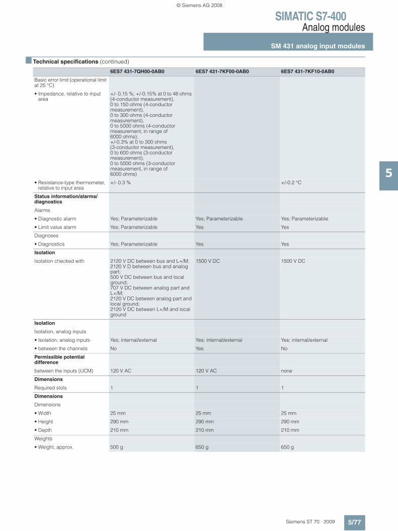
SIMATIC S7-400Analog modules
SM 431 analog input modules
5/77Siemens ST 70 · 2009
5
■ Technical specifications (continued)
6ES7 431-7QH00-0AB0 6ES7 431-7KF00-0AB0 6ES7 431-7KF10-0AB0
Basic error limit (operational limit at 25 °C)
• Impedance, relative to input area
+/- 0,15 %; +/-0.15% at 0 to 48 ohms (4-conductor measurement), 0 to 150 ohms (4-conductor measurement), 0 to 300 ohms (4-conductor measurement), 0 to 5000 ohms (4-conductor measurement, in range of 6000 ohms); +/-0.3% at 0 to 300 ohms (3-conductor measurement), 0 to 600 ohms (3-conductor measurement), 0 to 5000 ohms (3-conductor measurement, in range of 6000 ohms)
• Resistance-type thermometer, relative to input area
+/- 0.3 % +/-0.2 °C
Status information/alarms/diagnostics
Alarms
• Diagnostic alarm Yes; Parameterizable Yes; Parameterizable Yes; Parameterizable
• Limit value alarm Yes; Parameterizable Yes Yes
Diagnoses
• Diagnostics Yes; Parameterizable Yes Yes
Isolation
Isolation checked with 2120 V DC between bus and L+/M; 2120 V D between bus and analog part; 500 V DC between bus and local ground; 707 V DC between analog part and L+/M; 2120 V DC between analog part and local ground; 2120 V DC between L+/M and local ground
1500 V DC 1500 V DC
Isolation
Isolation, analog inputs
• Isolation, analog inputs Yes; internal/external Yes; internal/external Yes; internal/external
• between the channels No Yes No
Permissible potential difference
between the inputs (UCM) 120 V AC 120 V AC none
Dimensions
Required slots 1 1 1
Dimensions
Dimensions
• Width 25 mm 25 mm 25 mm
• Height 290 mm 290 mm 290 mm
• Depth 210 mm 210 mm 210 mm
Weights
• Weight, approx. 500 g 650 g 650 g
© Siemens AG 2008

SIMATIC S7-400Analog modules
SM 431 analog input modules
5/78 Siemens ST 70 · 2009
5
■ Ordering data Order No. Order No.
B3: Subject to export regulations: AL: N and ECCN: 5D992B1B6: Subject to export regulations: AL: N and ECCN: EAR99B7: Subject to export regulations: AL: N and ECCN: EAR99HB8: Subject to export regulations: AL: N and ECCN: EAR99S
SM 431 analog output module
16 inputs, non-floating, 13 bit 6ES7 431-0HH00-0AB0
8 inputs, floating, 13 bit 6ES7 431-1KF00-0AB0
8 inputs, floating, 14 bit, with linearization
6ES7 431-1KF10-0AB0
8 inputs, floating, 14 bit 6ES7 431-1KF20-0AB0
16 inputs, floating, 16 bit, process interrupt capability
6ES7 431-7QH00-0AB0
8 inputs, floating, 16 bit, process interrupt capability, for thermo-couples (I, U)
6ES7 431-7KF00-0AB0
8 inputs, floating, 16 bit, process interrupt capability, for temper-ature sensors
6ES7 431-7KF10-0AB0
Front connectors
48-pin
• with screw contacts, 1 item B7 6ES7 492-1AL00-0AA0
• with screw contacts, 84 items B6 6ES7 492-1AL00-1AB0
• with spring-loaded terminals, 1 item
6ES7 492-1BL00-0AA0
• with crimp contacts, 1 item B7 6ES7 492-1CL00-0AA0
• with crimp contacts, 84 items 6ES7 492-1CL00-1AB0
1 unit; for 6ES7 431-7KF00-0AB0; spare part, included in scope of delivery
6ES7431-7KF00-6AA0
SIMATIC TOP connect see page 5/131;Information about which compo-nents can be used for the respective module, see DT&IAMall or Catalog KT 10.2
Measuring range module for analog inputs
6ES7 974-0AA00-0AA0
1 module for 2 inputs (spare part)
Cover film for labeling strips 6ES7 492-2XX00-0AA0
Spare part
S7 SmartLabel V3.0
Software for automatic labeling of modules direct from the STEP 7 project
Single license B8 2XV9 450-1SL03-0YX0
Upgrade single license B8 2XV9 450-1SL03-0YX4
Labeling sheets for machine inscription
DIN A4, for printing using laser printer; pack of 10
petrol 6ES7 492-2AX00-0AA0
light-beige 6ES7 492-2BX00-0AA0
yellow 6ES7 492-2CX00-0AA0
red 6ES7 492-2DX00-0AA0
SIMATIC Manual Collection B3 6ES7 998-8XC01-8YE0
Electronic manuals on DVD, five languages: S7-200/300/400, C7, LOGO!, SIMATIC DP, PC, PG, STEP 7, engineering software, runtime software, PCS 7, SIMATIC HMI, SIMATIC NET
SIMATIC Manual Collection maintenance service for 1 year
B3 6ES7 998-8XC01-8YE2
Current "Manual Collection" DVD and the three subsequent updates
Manual "SIMATIC S7-400 programmable controller"
incl. instruction list
German 6ES7 498-8AA05-8AA0
English 6ES7 498-8AA05-8BA0
French 6ES7 498-8AA05-8CA0
Spanish 6ES7 498-8AA05-8DA0
Italian 6ES7 498-8AA05-8EA0
© Siemens AG 2008
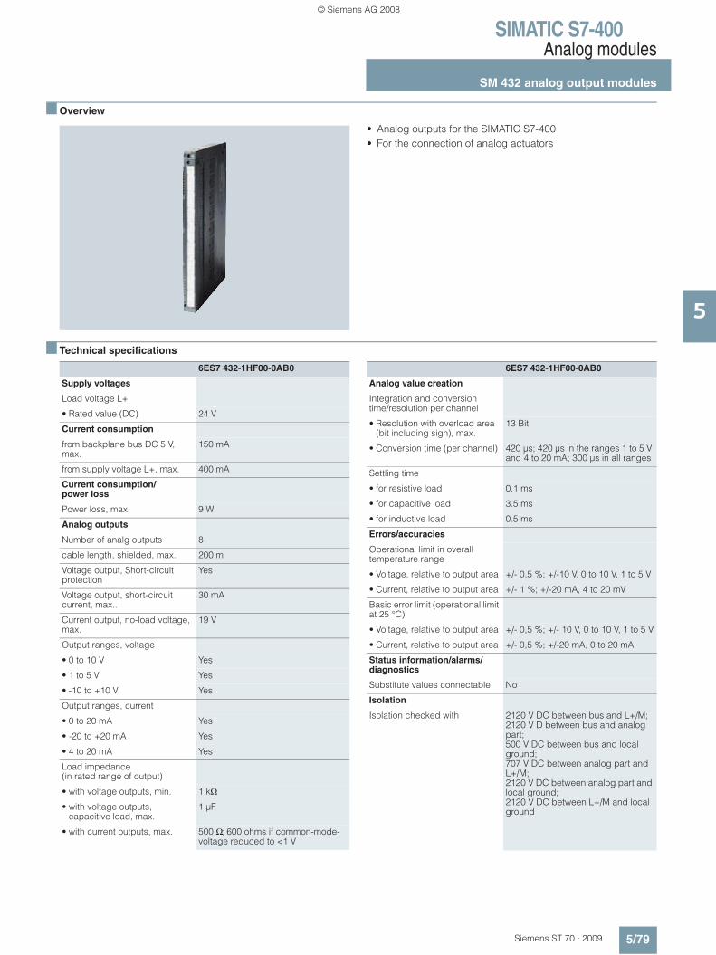
SIMATIC S7-400Analog modules
SM 432 analog output modules
5/79Siemens ST 70 · 2009
5
■ Overview
• Analog outputs for the SIMATIC S7-400• For the connection of analog actuators
■ Technical specifications
6ES7 432-1HF00-0AB0
Supply voltages
Load voltage L+
• Rated value (DC) 24 V
Current consumption
from backplane bus DC 5 V, max.
150 mA
from supply voltage L+, max. 400 mA
Current consumption/power loss
Power loss, max. 9 W
Analog outputs
Number of analg outputs 8
cable length, shielded, max. 200 m
Voltage output, Short-circuit protection
Yes
Voltage output, short-circuit current, max..
30 mA
Current output, no-load voltage, max.
19 V
Output ranges, voltage
• 0 to 10 V Yes
• 1 to 5 V Yes
• -10 to +10 V Yes
Output ranges, current
• 0 to 20 mA Yes
• -20 to +20 mA Yes
• 4 to 20 mA Yes
Load impedance (in rated range of output)
• with voltage outputs, min. 1 kΩ
• with voltage outputs, capacitive load, max.
1 μF
• with current outputs, max. 500 Ω; 600 ohms if common-mode-voltage reduced to <1 V
6ES7 432-1HF00-0AB0
Analog value creation
Integration and conversion time/resolution per channel
• Resolution with overload area (bit including sign), max.
13 Bit
• Conversion time (per channel) 420 μs; 420 μs in the ranges 1 to 5 V and 4 to 20 mA; 300 μs in all ranges
Settling time
• for resistive load 0.1 ms
• for capacitive load 3.5 ms
• for inductive load 0.5 ms
Errors/accuracies
Operational limit in overall temperature range
• Voltage, relative to output area +/- 0,5 %; +/-10 V, 0 to 10 V, 1 to 5 V
• Current, relative to output area +/- 1 %; +/-20 mA, 4 to 20 mV
Basic error limit (operational limit at 25 °C)
• Voltage, relative to output area +/- 0,5 %; +/- 10 V, 0 to 10 V, 1 to 5 V
• Current, relative to output area +/- 0,5 %; +/-20 mA, 0 to 20 mA
Status information/alarms/diagnostics
Substitute values connectable No
Isolation
Isolation checked with 2120 V DC between bus and L+/M; 2120 V D between bus and analog part; 500 V DC between bus and local ground; 707 V DC between analog part and L+/M; 2120 V DC between analog part and local ground; 2120 V DC between L+/M and local ground
© Siemens AG 2008
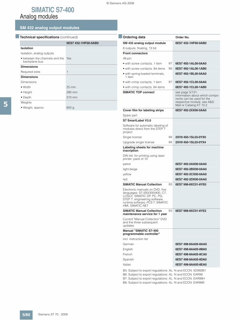
SIMATIC S7-400Analog modules
SM 432 analog output modules
5/80 Siemens ST 70 · 2009
5
■ Technical specifications (continued)
■ Ordering data Order No.
B3: Subject to export regulations: AL: N and ECCN: 5D992B1B6: Subject to export regulations: AL: N and ECCN: EAR99B7: Subject to export regulations: AL: N and ECCN: EAR99HB8: Subject to export regulations: AL: N and ECCN: EAR99S
6ES7 432-1HF00-0AB0
Isolation
Isolation, analog outputs
• between the channels and the backplane bus
Yes
Dimensions
Required slots 1
Dimensions
Dimensions
• Width 25 mm
• Height 290 mm
• Depth 210 mm
Weights
• Weight, approx. 650 g
SM 432 analog output module 6ES7 432-1HF00-0AB0
8 outputs, floating, 13 bit
Front connectors
48-pin
• with screw contacts, 1 item B7 6ES7 492-1AL00-0AA0
• with screw contacts, 84 items B6 6ES7 492-1AL00-1AB0
• with spring-loaded terminals, 1 item
6ES7 492-1BL00-0AA0
• with crimp contacts, 1 item B7 6ES7 492-1CL00-0AA0
• with crimp contacts, 84 items 6ES7 492-1CL00-1AB0
SIMATIC TOP connect see page 5/131;Information about which compo-nents can be used for the respective module, see A&D Mall or Catalog KT 10.2
Cover film for labeling strips 6ES7 492-2XX00-0AA0
Spare part
S7 SmartLabel V3.0
Software for automatic labeling of modules direct from the STEP 7 project
Single license B8 2XV9 450-1SL03-0YX0
Upgrade single license B8 2XV9 450-1SL03-0YX4
Labeling sheets for machine inscription
DIN A4, for printing using laser printer; pack of 10
petrol 6ES7 492-2AX00-0AA0
light-beige 6ES7 492-2BX00-0AA0
yellow 6ES7 492-2CX00-0AA0
red 6ES7 492-2DX00-0AA0
SIMATIC Manual Collection B3 6ES7 998-8XC01-8YE0
Electronic manuals on DVD, five languages: S7-200/300/400, C7, LOGO!, SIMATIC DP, PC, PG, STEP 7, engineering software, runtime software, PCS 7, SIMATIC HMI, SIMATIC NET
SIMATIC Manual Collection maintenance service for 1 year
B3 6ES7 998-8XC01-8YE2
Current "Manual Collection" DVD and the three subsequent updates
Manual "SIMATIC S7-400 programmable controller"
incl. instruction list
German 6ES7 498-8AA05-8AA0
English 6ES7 498-8AA05-8BA0
French 6ES7 498-8AA05-8CA0
Spanish 6ES7 498-8AA05-8DA0
Italian 6ES7 498-8AA05-8EA0
© Siemens AG 2008

SIMATIC S7-400SIPLUS analog modules
SIPLUS SM 431 analog input moduleSIPLUS SM 432 analog output module
5/81Siemens ST 70 · 2009
5
■ Overview SIPLUS SM 431
• Analog inputs for SIMATIC S7-400 • Connecting voltage sensors and current sensors,
thermo elements, resistors and resistance thermometers • Resolution 13 to 16 bit
For further technical documentation on SIPLUS, see:
http://www.siemens.com/siplus-techdoku
■ Ordering data Order No.
■ Overview SIPLUS SM 432
• Analog outputs for SIMATIC S7-400 • For connection of analog actuators
For further technical documentation on SIPLUS, see:
http://www.siemens.com/siplus-techdoku
■ Ordering data Order No.
Analog input module SIPLUS SM 431
Order No. 6AG1 431-0HH00-4AB0
Order No. based on 6ES7 431-0HH00-0AB0
Ambient conditions Suited for exceptional medial exposure (e. g. by chlorine sulfur atmosphere).
Technical data The technical data are identical with those of the based-on modules.
SIPLUS SM 431 analog input module
6AG1 431-0HH00-4AB0
(medial exposure)
16 inputs, non-floating, 13 bit
Accessories see S7-400 analog input modules SM 431, page 5/78
Analog output module SIPLUS SM 432
Order No. 6AG1 432-1HF00-4AB0
Order No. based on 6ES7 432-0HF00-0AB0
Ambient conditions Suited for exceptional medial exposure (e. g. by chlorine sulfur atmosphere).
Technical data The technical data are identical with those of the based-on modules.
SIPLUS SM 432 analog output module
6AG1 432-1HF00-4AB0
(medium exposure)
8 outputs, floating, 13 bit
Accessories see S7-400 analog output modules SM 432, page 5/80
© Siemens AG 2008

SIMATIC S7-400Function modules
FM 450-1 counter module
5/82 Siemens ST 70 · 2009
5
■ Overview
• Two-channel intelligent counter module for simple counting tasks
• For direct connection of incremental encoders• Comparison function with 2 specifiable comparison values• Integrated digital outputs for outputting the response when the
comparison values are reached
Note
SIMODRIVE Sensor/Motion Connect 500 feature incremental encoders and preassembled connecting cables for counting and positioning functions.
http://www.siemens.com/simatic-technology
■ Technical specifications
6ES7 450-1AP00-0AE0
Supply voltages
Aux. voltage 1L+, load voltage 2 L+
• Rated value (DC) 24 V
• permissible range, lower limit (DC)
20.4 V; dynamic 18.5 V
• permissible range, upper limit (DC)
28.8 V; dynamic 30.2 V
• non-periodic skip- Duration 500 ms- Recovery time 50 s- Value 35 V
Load voltage 1L+
• Reverse polarity protection Yes
Load voltage 2L+
• Reverse polarity protection Yes
Current consumption
from load voltage 1L+ (without load), max.
40 mA
from backplane bus DC 5 V, max.
450 mA
Current consumption/power loss
Power loss, typ. 9 W
Connection point
required front connectors 1x 48-polig
Digital inputs
Number of digital inputs 6
Functions 1 for gate start, 1 for gate stop, 1 for setting the counter
Input voltage
• for signal "0" -28.8 to +5 V
• for signal "1" +11 to +28.8 V
Input current
• for signal "1", typ. 9 mA
6ES7 450-1AP00-0AE0
Input delay (for rated value of input voltage)
• Input frequency (with 0.1 ms delay), max.
200 kHz
• for standard inputs- programmable Yes- at "0" to "1", max. 2.5 μs; >= 2.5 μs (200 kHz);
<= 25 μs (20 kHz)
Digital outputs
Number of digital outputs 6
Short-circuit protection of the output
Yes; clocked electronically
Limitation of inductive shutdown voltage to
2L+ (-39 V)
Output voltage
• for signal "0" (DC), max. 3 V
• for signal "1", min. 2L+ (-1.5 V)
Output current
• for signal "1" rated value 0.5 A
• for signal "1" permissible range for 0 to 60 °C, min.
5 mA
• for signal "1" permissible range for 0 to 60 °C, max.
0.6 A
Output delay with resistive load
• "0" to "1", max. 300 μs
Encoder supply
5 V encoder supply
• 5 V Yes; 5.2 V +/-2 %
• Short-circuit protection Yes
• Output current, max. 300 mA
24 V encoder supply
• 24 V Yes; 1L+ (-3 V)
• Short-circuit protection Yes
• Output current, max. 300 mA
© Siemens AG 2008
SIMATIC S7-400Function modules
FM 450-1 counter module
5/83Siemens ST 70 · 2009
5
■ Technical specifications (continued)
■ Ordering data Order No.
B6: Subject to export regulations: AL: N and ECCN: EAR99B7: Subject to export regulations: AL: N and ECCN: EAR99H
6ES7 450-1AP00-0AE0
Encoder
Connectable encoders
• Incremental encoder (symmetrical)
Yes; with 2 pulse strings offset by 90°
• Incremental encoder (asymmetrical)
Yes
• 24 V initiator Yes
• 24 V directional element Yes; 1 pulse train, 1 direction level
Counters
Number of counter inputs 2; 32 bit or +/-31 bit
Counter input 5 V
• Type RS 422
• Terminating resistor 220 Ω
• Differential input voltage min. 0.5 V
• Counter frequency, max. 500 kHz
Counter input 24 V
• Input voltage, for signal "0" -30 to +5 V
• Input voltage, for signal "1" +11 to +30 V
• Input current, for signal "1", typ. 9 mA
• Counter frequency, max. 200 kHz
• Minimum pulse width >= 2.5 μs (200 kHz); <= 25 μs (20 kHz) (parameterizable)
Parameter
Remark Assigned binary addresses: 64 bytes/64 bytes
Isolation
Isolation checked with 500 V
Isolation
Galvanic isolation, digital inputs
• between the channels and the backplane bus
Yes; Optocoupler
Isolation, digital outputs
• between the channels and the backplane bus
Yes; Optocoupler
Isolation counter
• between the channels and the backplane bus
Yes; Optocoupler
Permissible potential difference
between different circuits 75 V DC / 60 V AC
Dimensions
Dimensions
• Width 25 mm
• Height 290 mm
• Depth 210 mm
Weights
• Weight, approx. 650 g
FM 450-1 counter module 6ES7 450-1AP00-0AE0
with 2 channels, max. 500 kHz; for incremental encoder
Front connectors
48-pin
• with screw contacts, 1 item B7 6ES7 492-1AL00-0AA0
• with screw contacts, 84 items B6 6ES7 492-1AL00-1AB0
• with spring-loaded terminals, 1 item
6ES7 492-1BL00-0AA0
• with crimp contacts, 1 item B7 6ES7 492-1CL00-0AA0
• with crimp contacts, 84 items 6ES7 492-1CL00-1AB0
Front covers for CPU and function modules
6ES7 492-1XL00-0AA0
Spare part
© Siemens AG 2008
SIMATIC S7-400Function modules
SIPLUS FM 450-1 counter module
5/84 Siemens ST 70 · 2009
5
■ Overview
• Two-channel, intelligent counter module for simple counting tasks
• For direct connection of incremental sensors • Comparison functions with two definable comparison values • Integrated digital outputs for the output of the reaction on
reaching the comparison values
For further technical documentation on SIPLUS, see:
http://www.siemens.com/siplus-techdoku
Note:
We offer incremental sensors and preassembled connecting cables for counting and positioning functions under SIMODRIVE Sensor or Motion Connect 500.
http://www.siemens.com/simatic-technology
■ Ordering data Order No.
SIPLUS FM 450-1 counter module
Order No. 6AG1 450-1AP00-4AE0
Order No. based on 6ES7 450-1AP00-0AE0
Ambient conditions Suited for exceptional medial exposure (e. g. by chlorine sulfur atmosphere)
Technical data The technical data are identical to that of the based-on modules.
FM 450-1 counter module 6AG1 450-1AP00-4AE0
(medium exposure)
with 2 channels, max. 500 kHz; for incremental encoder
Accessories see FM 450-1, page 5/83
© Siemens AG 2008
SIMATIC S7-400Function modules
FM 451 positioning module
5/85Siemens ST 70 · 2009
5
■ Overview
• Three-channel positioning module for rapid traverse/creep speed drives
• 4 digital outputs per channel for motor control• Incremental or synchro-serial position decoding
Note
SIMODRIVE Sensor/Motion Connect 500 feature position-measuring systems and preassembled connecting cables for counting and positioning functions.
http://www.siemens.com/simatic-technology
■ Technical specifications
6ES7 451-3AL00-0AE0
Supply voltages
Rated value
• DC 24 V Yes
Current consumption
Current consumption, max. 550 mA
Connection point
required front connectors 1x 48-pin
Digital inputs
Number of digital inputs 12; 4 per axis
Functions Reference cams, reversing cams, flying actual value setting, start/stop positioning
Input voltage
• Rated value, DC 24 V
• for signal "0" -3 to +5 V
• for signal "1" 11 to 30 V
Input current
• for signal "1", typ. 6 mA
• for 2-wire BERO- for signal "1", typ. 30 mA
Digital outputs
Number of digital outputs 12; 4 per axis
Functions Rapid traverse, creep, run right, run left
Short-circuit protection of the output
Yes
Output voltage
• for signal "1", min. UP - 3 V
Output current
• for signal "1" permissible range for 0 to 55 °C, max.
600 mA; with UPmax
• for signal "0" residual current, max.
0.5 mA
6ES7 451-3AL00-0AE0
Encoder supply
5 V encoder supply
• 5 V Yes
• Output current, max. 210 mA
• Cable length, max. 35 m; at max. 210 mA
24 V encoder supply
• 24 V Yes
• Output current, max. 300 mA
• Cable length, max. 100 m; at max. 300 mA
Absolute encoder (SSI) encoder supply
• Absolute encoder (SSI) Yes
• Output voltage 24 V DC
• Output current, max. 300 mA
• Cable length, max. 300 m; at max.156 kbit/s
Encoder
Connectable encoders
• Incremental encoder (symmetrical)
Yes
• Incremental encoder (asymmetrical)
Yes
• Absolute encoder (SSI) Yes
Encoder signals, incremental encoder (symmetrical)
• Trace mark signals A, notA, B, notB
• Zero mark signal N, notN
• Input signal 5 V difference signal (phys. RS 422)
• Input frequency, max. 1 MHz
Encoder signals, incremental encoder (asymmetrical)
• Trace mark signals A. B
• Zero mark signal N
• Input voltage 24 V
• Input frequency, max. 50 kHz; for 25 m cable length, 25 kHz for 100 m cable length
• cable length, shielded, max. 100 m
© Siemens AG 2008
SIMATIC S7-400Function modules
FM 451 positioning module
5/86 Siemens ST 70 · 2009
5
■ Technical specifications (continued)
■ Ordering data Order No.
B6: Subject to export regulations: AL: N and ECCN: EAR99B7: Subject to export regulations: AL: N and ECCN: EAR99H
6ES7 451-3AL00-0AE0
Encoder signals, absolute encoder (SSI)
• Input signal 5 V difference signal (phys. RS 422)
• Data signal DATA. notDATA
• Clock signal CL. notCL
• Telegram length 13 or 25 bit serial
• Clock frequency, max. 1.25 MHz
• Gray code 1
• cable length, shielded, max. 300 m; at max. 156 kBit/s
Isolation
Galvanic isolation, digital inputs
• galvanic isolation, digital inputs Yes
Isolation, digital outputs
• Galvanic isolation, digital outputs
Yes
Environmental requirements
Operating termperature
• min. 0 °C
• max. 55 °C
Storage/transport temperature
• min. -40 °C
• max. 70 °C
Relative humidity
• Humidity class F Yes
Degree of protection
IP 20 Yes
Dimensions
Dimensions
• Width 50 mm
• Height 290 mm
• Depth 210 mm
Weights
• Weight, approx. 1 300 g
FM 451 positioning module 6ES7 451-3AL00-0AE0
for rapid traverse and creep speed drives
Front connector
48-pin
• with screw contacts, 1 item B7 6ES7 492-1AL00-0AA0
• with screw contacts, 84 items B6 6ES7 492-1AL00-1AB0
• with spring-loaded terminals, 1 item
6ES7 492-1BL00-0AA0
• with crimp contacts, 1 item B7 6ES7 492-1CL00-0AA0
• with crimp contacts, 84 items 6ES7 492-1CL00-1AB0
Front covers for CPU and function modules
6ES7 492-1XL00-0AA0
Spare part
Signal cable
Pre-assembled for HTL encoder, UL/DESINA
6FX5 0 7 2-2AL00- 7 7 7 7
Pre-assembled for SSI absolute encoder, UL/DESINA
6FX5 0 7 2-2CC11- 7 7 7 7
Pre-assembled for TTL encoder 6FX2001-1, UL/DESINA
6FX5 0 7 2-2CD01- 7 7 7 7
Pre-assembled for TTL encoder 24 V, UL/DESINA
6FX5 0 7 2-2CD24- 7 7 7 7
Not crimped 0
Module end crimped, connector case supplied
1
Motor end crimped, connector case supplied
4
0 m 1100 m 2200 m 3
0 m A10 m B20 m C30 m D40 m E50 m F60 m G70 m H80 m J90 m K
0 m A1 m B2 m C3 m D4 m E5 m F6 m G7 m H8 m J0 m K
0.0 m 00.1 m 10.2 m 20.3 m 30.4 m 40.5 m 50.6 m 60.7 m 70.8 m 8
© Siemens AG 2008

SIMATIC S7-400Function modules
FM 452 cam controller
5/87Siemens ST 70 · 2009
5
■ Overview
• Extremely high-speed electronic cam controller• Low-cost alternative to mechanical cam controllers• 32 cam tracks, 16 onboard digital outputs for direct output of
actions• Incremental or synchro-serial position decoding
Note:
SIMODRIVE Sensor/Motion Connect 500 feature position-measuring systems and preassembled connecting cables for counting and positioning functions.
http://www.siemens.com/simatic-technology
■ Technical specifications
6ES7 452-1AH00-0AE0
Supply voltages
Rated value
• DC 24 V Yes
Current consumption
Current consumption, max. 500 mA
Connection point
required front connectors 1x 48-pin
Digital inputs
Number of digital inputs 11
Functions Reference point switch, flying actual value setting/length measurement, brake release, enable track output no. 3 to 10
Input voltage
• Rated value, DC 24 V
• for signal "0" -28.8 to +5 V
• for signal "1" 11 to 28.8 V
Input current
• for signal "0", max. (permissible quiescent current)
2 mA
• for 2-wire BERO- for signal "1", typ. 9 mA
Digital outputs
Number of digital outputs 16
Functions Cam tracks
Short-circuit protection of the output
Yes
Output voltage
• Rated value (DC) 24 V
• for signal "1", min. UP - 0.8 V
Output current
• for signal "1" permissible range for 0 to 55 °C, max.
600 mA; with UPmax
• for signal "0" residual current, max.
0.5 mA
6ES7 452-1AH00-0AE0
Encoder supply
5 V encoder supply
• 5 V Yes
• Output current, max. 300 mA
• Cable length, max. 32 m
24 V encoder supply
• 24 V Yes
• Output current, max. 300 mA
• Cable length, max. 100 m
Encoder
Connectable encoders
• Incremental encoder (symmetrical)
Yes
• Incremental encoder (asymmetrical)
Yes
• Absolute encoder (SSI) Yes
• 2-wire BEROS Yes
Encoder signals, incremental encoder (symmetrical)
• Trace mark signals A. notA. B. notB
• Zero mark signal N. notN
• Input signal 5 V difference signal (phys. RS 422)
• Input frequency, max. 1 MHz
Encoder signals, incremental encoder (asymmetrical)
• Trace mark signals A. B
• Zero mark signal N
• Input voltage 24 V
• Input frequency, max. 50 kHz; 50 kHz for 25 m cable length; 25 kHz for 100 m cable length
© Siemens AG 2008

SIMATIC S7-400Function modules
FM 452 cam controller
5/88 Siemens ST 70 · 2009
5
■ Technical specifications (continued)
■ Ordering data Order No.
B6: Subject to export regulations: AL: N and ECCN: EAR99B7: Subject to export regulations: AL: N and ECCN: EAR99H
6ES7 452-1AH00-0AE0
Encoder signals, absolute encoder (SSI)
• Input signal 5 V difference signal (phys. RS 422)
• Data signal DATA. notDATA
• Clock signal CL. notCL
• Telegram length 13 or 25 bit serial
• Clock frequency, max. 1 MHz
• Gray code 1
• cable length, shielded, max. 300 m; at max. 125 kHz
Isolation
Galvanic isolation, digital inputs
• galvanic isolation, digital inputs No
Isolation, digital outputs
• Galvanic isolation, digital outputs
No
Environmental requirements
Operating termperature
• min. 0 °C
• max. 55 °C
Storage/transport temperature
• min. -40 °C
• max. 70 °C
Relative humidity
• Humidity class F Yes
Degree of protection
IP 20 Yes
Dimensions
Dimensions
• Width 25 mm
• Height 290 mm
• Depth 210 mm
Weights
• Weight, approx. 650 g
FM 452 electronic cam controller
6ES7 452-1AH00-0AE0
Front covers for CPU and function modules
6ES7 492-1XL00-0AA0
Spare part
Front connector
48-pin
• with screw contacts, 1 item B7 6ES7 492-1AL00-0AA0
• with screw contacts, 84 items B6 6ES7 492-1AL00-1AB0
• with spring-loaded terminals, 1 item
6ES7 492-1BL00-0AA0
• with crimp contacts, 1 item B7 6ES7 492-1CL00-0AA0
• with crimp contacts, 84 items 6ES7 492-1CL00-1AB0
Signal cable
Pre-assembled for HTL and TTL encoder, without Sub-D connector, UL/DESINA
6FX5 002-2CA12-7777
Pre-assembled for SSI absolute encoder 6FX2001-5, without Sub-D connector, UL/DESINA
6FX5 002-2CC12-7777
Length code see FM 451, page 5/86
© Siemens AG 2008
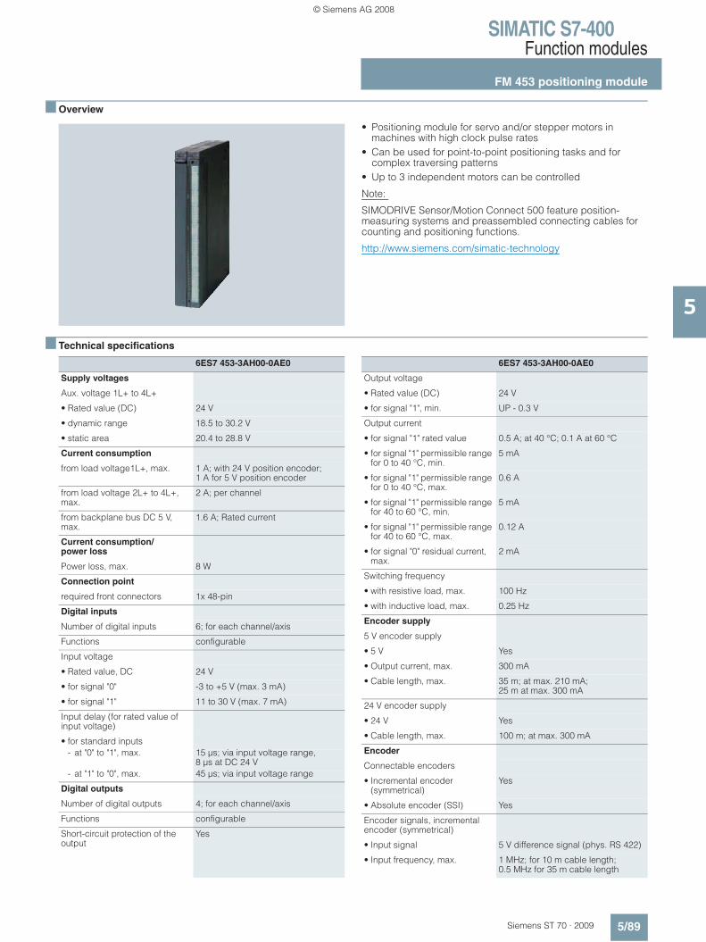
SIMATIC S7-400Function modules
FM 453 positioning module
5/89Siemens ST 70 · 2009
5
■ Overview
• Positioning module for servo and/or stepper motors in machines with high clock pulse rates
• Can be used for point-to-point positioning tasks and for complex traversing patterns
• Up to 3 independent motors can be controlled
Note:
SIMODRIVE Sensor/Motion Connect 500 feature position-measuring systems and preassembled connecting cables for counting and positioning functions.
http://www.siemens.com/simatic-technology
■ Technical specifications
6ES7 453-3AH00-0AE0
Supply voltages
Aux. voltage 1L+ to 4L+
• Rated value (DC) 24 V
• dynamic range 18.5 to 30.2 V
• static area 20.4 to 28.8 V
Current consumption
from load voltage1L+, max. 1 A; with 24 V position encoder; 1 A for 5 V position encoder
from load voltage 2L+ to 4L+, max.
2 A; per channel
from backplane bus DC 5 V, max.
1.6 A; Rated current
Current consumption/power loss
Power loss, max. 8 W
Connection point
required front connectors 1x 48-pin
Digital inputs
Number of digital inputs 6; for each channel/axis
Functions configurable
Input voltage
• Rated value, DC 24 V
• for signal "0" -3 to +5 V (max. 3 mA)
• for signal "1" 11 to 30 V (max. 7 mA)
Input delay (for rated value of input voltage)
• for standard inputs- at "0" to "1", max. 15 μs; via input voltage range,
8 μs at DC 24 V- at "1" to "0", max. 45 μs; via input voltage range
Digital outputs
Number of digital outputs 4; for each channel/axis
Functions configurable
Short-circuit protection of the output
Yes
6ES7 453-3AH00-0AE0
Output voltage
• Rated value (DC) 24 V
• for signal "1", min. UP - 0.3 V
Output current
• for signal "1" rated value 0.5 A; at 40 °C; 0.1 A at 60 °C
• for signal "1" permissible range for 0 to 40 °C, min.
5 mA
• for signal "1" permissible range for 0 to 40 °C, max.
0.6 A
• for signal "1" permissible range for 40 to 60 °C, min.
5 mA
• for signal "1" permissible range for 40 to 60 °C, max.
0.12 A
• for signal "0" residual current, max.
2 mA
Switching frequency
• with resistive load, max. 100 Hz
• with inductive load, max. 0.25 Hz
Encoder supply
5 V encoder supply
• 5 V Yes
• Output current, max. 300 mA
• Cable length, max. 35 m; at max. 210 mA; 25 m at max. 300 mA
24 V encoder supply
• 24 V Yes
• Cable length, max. 100 m; at max. 300 mA
Encoder
Connectable encoders
• Incremental encoder (symmetrical)
Yes
• Absolute encoder (SSI) Yes
Encoder signals, incremental encoder (symmetrical)
• Input signal 5 V difference signal (phys. RS 422)
• Input frequency, max. 1 MHz; for 10 m cable length; 0.5 MHz for 35 m cable length
© Siemens AG 2008
SIMATIC S7-400Function modules
FM 453 positioning module
5/90 Siemens ST 70 · 2009
5
■ Technical specifications (continued)
■ Ordering data Order No. Order No.
B6: Subject to export regulations: AL: N and ECCN: EAR99B7: Subject to export regulations: AL: N and ECCN: EAR99H
6ES7 453-3AH00-0AE0
Encoder signals, absolute encoder (SSI)
• Input signal 5 V difference signal (phys. RS 422)
• Clock frequency, max. 1.25 Mbit/s at 10 cable length (2.5 Mbit/s available soon)
• cable length, shielded, max. 250 m; at max. 156 kBit/s
Drive interface
Signal input I
• Type Drive interface step, signal input "READY 1"
• Function "Power section ready" where Ui < 1 V, Ii = 2mA
Signal output I
• Type 5 V (phys. RS 422)
• Function Clock pulse, direction, enable, current control
• Differential output voltage, min. 2 V; RL = 100 Ohm
• Differential output voltage for signal "0", max.
1.1 V; Io = 30 mA
• Differential output voltage, for signal "1", min.
3.7 V; Io = -30 mA
• Load impedance 55 Ω
• Pulse frequency 200 kHz; 500 kHz available soon
• Cable length, max. 35 m; 35 m with symm. transmission; 10 m with asymm. transmission
Signal output II
• Type Contact relay
• Function Drive disconnection for operation
• Load 1 A/50 V/30 VA DC
Signal output III
• Type Analog output
• Function Drive interface Servo: Setpoint output for drive
• Output voltage -10 to +10 V
• Output current 3 to +3 mA
• Cable length, max. 30 m
6ES7 453-3AH00-0AE0
Isolation
Galvanic isolation, digital inputs
• galvanic isolation, digital inputs Yes; Optocoupler
Isolation, digital outputs
• Galvanic isolation, digital outputs
Yes; Optocoupler
Environmental requirements
Operating termperature
• min. 0 °C
• max. 55 °C
Storage/transport temperature
• min. -40 °C
• max. 70 °C
Relative humidity
• Humidity class F No
Degree of protection
IP 20 Yes
Dimensions
Dimensions
• Width 50 mm
• Height 290 mm
• Depth 210 mm
Weights
• Weight, approx. 1 620 g
FM 453 positioning module 6ES7 453-3AH00-0AE0
with 3 channels/axes
Setpoint connecting cable
for 3 servo motors 6FX2 002-3AD01-7777
for 3 stepper motors 6FX2 002-3AB04-7777
for 2 servo motors / 1 stepper motor
6FX2 002-3AB02-7777
for 1 servo motor / 2 stepper motors
6FX2 002-3AB03-7777
Length code see FM 451. page 5/86
Front covers for CPU and function modules
6ES7 492-1XL00-0AA0
Spare part
Front connector
48-pin
• with screw contacts, 1 item B7 6ES7 492-1AL00-0AA0
• with screw contacts, 84 items B6 6ES7 492-1AL00-1AB0
• with spring-loaded terminals, 1 item
6ES7 492-1BL00-0AA0
• with crimp contacts, 1 item B7 6ES7 492-1CL00-0AA0
• with crimp contacts, 84 items 6ES7 492-1CL00-1AB0
Signal cable
Pre-assembled for SSI absolute encoder, UL/DESINA
6FX5 072-2CC11-7777
Pre-assembled for TTL encoder 6FX2001-1, UL/DESINA
6FX5 072-2CD01-7777
Pre-assembled for TTL encoder 24 V, UL/DESINA
6FX5 072-2CD24-7777
Length code see FM 451, page 5/86
© Siemens AG 2008

SIMATIC S7-400Function modules
FM 455 controller module
5/91Siemens ST 70 · 2009
5
■ Overview
• 16-channel closed-loop control module for universal closed-loop control tasks
• Suitable for temperature, pressure, and flow control systems• User-friendly online self-optimization for temperature controls• Preprogrammed controller structures• 2 control algorithms• 2 versions:
- FM 455 C as continuous-action controller- FM 455 S as step controller or pulse controller
• With 16 analog outputs (FM 455 C) or 32 digital outputs (FM 455 S) for actuators
■ Technical specifications
6ES7 455-0VS00-0AE0
6ES7 455-1VS00-0AE0
Supply voltages
Load voltage L+
• Rated value (DC) 24 V 24 V
• permissible range, lower limit (DC)
20.4 V 20.4 V
• permissible range, upper limit (DC)
28.8 V 28.8 V
Current consumption
from load voltage L+ (without load), max.
440 mA; typ. 370 mA
400 mA;typ. 330 mA
Current consumption/power loss
Power loss, max. 17.3 W 16.2 W
Power loss, typ. 12 W 10.7 W
Connection point
required front connectors 2x 48-pin 2x 48-pin
Digital inputs
Number of digital inputs 16 16
Input characteristic curve to IEC 1131, Type 2
Yes Yes
Input voltage
• Rated value, DC 24 V 24 V
• for signal "0" -3 to +5 V -3 to +5 V
• for signal "1" 13 to 30 V 13 to 30 V
Input current
• for signal "1", typ. 7 mA 7 mA
Cable length
• cable length, shielded, max.
1 000 m 1 000 m
• Cable length unshielded, max.
600 m 600 m
Digital outputs
Number of digital outputs 32
Short-circuit protection of the output
Yes; Electronic
6ES7 455-0VS00-0AE0
6ES7 455-1VS00-0AE0
Limitation of inductive shutdown voltage to
L+ (-1.5 V)
Lamp load, max. 5 W
Controlling a digital input Yes
Output voltage
• for signal "1", min. L+ (-2.5 V)
Output current
• for signal "1" rated value 0.1 A
• for signal "1" permissible range for 0 to 60 °C, min.
5 mA
• for signal "1" permissible range for 0 to 60 °C, max.
150 mA
• for signal "0" residual current, max.
0.5 mA
Parallel switching of 2 outputs
• for logic links Yes
Switching frequency
• with resistive load, max. 100 Hz
• with inductive load, max. 0.5 Hz
• on lamp load, max. 100 Hz
Load impedance range
• lower limit 240 Ω
• upper limit 4 kΩ
• cable length, shielded, max.
1 000 m
• Cable length unshielded, max.
600 m
Analog inputs
Number of analog inputs 16; with thermo-couples or 2-wire connection; 8 with Pt 100 or 4-wire connection
16; with thermo-couples or 2-wire connection; 8 with Pt 100 or 4-wire connection
© Siemens AG 2008

SIMATIC S7-400Function modules
FM 455 controller module
5/92 Siemens ST 70 · 2009
5
■ Technical specifications (continued)
6ES7 455-0VS00-0AE0
6ES7 455-1VS00-0AE0
cable length, shielded, max. 200 m; 50 m at 80 mV and thermocouples
200 m; 50 m at 80 mV and thermocouples
Input ranges (rated values), voltages
• 0 to +10 V Yes Yes
• -1.75 to +11.75 V Yes Yes
• -80 mV to +80 mV Yes Yes
Input ranges (rated values), currents
• 0 to 20 mA Yes Yes
• 0 to 23.5 mA Yes Yes
• -3.5 to +23.5 mA Yes Yes
• 4 to 20 mA Yes Yes
Input ranges (rated values), thermoelements
• Type B Yes Yes
• Type J Yes Yes
• Type K Yes Yes
• Type R Yes Yes
• Type S Yes Yes
Input ranges (rated values), resistance thermometers
• Pt 100 Yes Yes
• permissible input frequency for voltage input (destruction limit), max.
20 V 20 V
• permissible input current for current input (destruction limit), max.
40 mA 40 mA
Characteristic curve linear-ization
• programmable Yes Yes- for thermoelements Typ B. J. K. R. S Typ B. J. K. R. S- for thermoresistor Pt100 (Standard) Pt100 (Standard)
Temperature compensation
• internal temperature compensation
Yes; parametrizable Yes; parametrizable
• external temperature compensation with Pt100
Yes; parametrizable Yes; parametrizable
Analog outputs
Number of analg outputs 16
cable length, shielded, max. 200 m; 50m at 80 mV and thermocouples
Voltage output, Short-circuit protection
Yes
Voltage output, short-circuit current, max..
25 mA
Current output, no-load voltage, max.
18 V
6ES7 455-0VS00-0AE0
6ES7 455-1VS00-0AE0
Output ranges, voltage
• 0 to 10 V Yes
• -10 to +10 V Yes
Output ranges, current
• 0 to 20 mA Yes
• -20 to +20 mA Yes
• 4 to 20 mA Yes
Connection of actuators
• for voltage output 2-conductor connection
Yes
• for current output 2-conductor connection
Yes
Load impedance (in rated range of output)
• with voltage outputs, min. 1 kΩ
• with voltage outputs, capacitive load, max.
1 μF
• with current outputs, max. 500 Ω
• with current outputs, inductive load, max.
1 mH
Analog value creation
Measurement principle integrating integrating
Integration and conversion time/resolution per channel
• Resolution with overload area (bit including sign), max.
14 Bit; 12 or 14 bit, parameterizable
14 Bit; 12 or 14 bit, parameterizable
• Conversion time (per channel)
16.67 ms; at 12 bits: 16 2/3 ms at 60 Hz, 20 ms at 50 Hz; at 14 bits: 100 ms at 50 and 60 Hz
16.67 ms; at 12 bits: 16 2/3 ms at 60 Hz, 20 ms at 50 Hz; at 14 bits: 100 ms at 50 and 60 Hz
Settling time
• for resistive load 0.2 ms 0.1 ms
• for capacitive load 3.3 ms 3.3 ms
• for inductive load 0.5 ms 0.5 ms
Encoder
Connection of signal encoders
• for voltage measurement Yes Yes
• for current measurement as 4-wire transducer
Yes Yes
Connectable encoders
• 2-wire BEROS Yes Yes- permissible quiescent
current (2-wire BEROS), max.
1.5 mA 1.5 mA
Errors/accuracies
Linearity error (relative to input area)
+/- 0.05 % +/- 0.05 %
© Siemens AG 2008
SIMATIC S7-400Function modules
FM 455 controller module
5/93Siemens ST 70 · 2009
5
■ Technical specifications (continued)
■ Ordering data Order No. Order No.
B6: Subject to export regulations: AL: N and ECCN: EAR99B7: Subject to export regulations: AL: N and ECCN: EAR99H
6ES7 455-0VS00-0AE0
6ES7 455-1VS00-0AE0
Temperature error (relative to input areas)
+/- 0.005 %/K +/- 0.005 %/K
Linearity error (relative to output area)
+/- 0.05 %
Temperature error (relative to output area)
+/- 0.02 %/K
Operational limit in overall temperature range
• Voltage, relative to input area
+/-0.6 to +/-1% +/-0.6 to +/-1%
• Current, relative to input area
+/-0.6 to +/-1% +/-0.6 to +/-1%
• Resistance-type thermometer, relative to input area
+/-0.6 to +/-1% +/-0.6 to +/-1%
• Voltage, relative to output area
+/- 0.5 %
• Current, relative to output area
+/- 0.6 %
Basic error limit (operational limit at 25 °C)
• Voltage, relative to input area
+/-0.4 to +/-0.6% +/-0.4 to +/-0.6%
• Current, relative to input area
+/-0.4 to +/-0.6% +/-0.4 to +/-0.6%
• Resistance-type thermometer, relative to input area
+/-0.4 to +/-0.6% +/-0.4 to +/-0.6%
• Voltage, relative to output area
+/- 0.4 %
• Current, relative to output area
+/- 0.5 %
6ES7 455-0VS00-0AE0
6ES7 455-1VS00-0AE0
Interference voltage suppression for f = n x (fl +/- 1 %), fl = interference frequency
• Series mode interference (peak value of interference < rated value of input range), min.
40 dB 40 dB
• common mode voltage (USS < 2.5 V) , min.
70 dB 70 dB
Control technology
Number of closed loop controllers
16; with thermo-couples or 2-wire connection; 8 with Pt 100 or 4-wire connection
16; with thermo-couples or 2-wire connection; 8 with Pt 100 or 4-wire connection
Status information/alarms/diagnostics
Substitute values connectable
Yes; Parameterizable
Yes; Parameterizable
Isolation
Isolation checked with 500 V DC 500 V DC
Isolation
Isolation, controller
• between the channels No No
• between the channels and the backplane bus
Yes; Optocoupler Yes; Optocoupler
Permissible potential difference
between inputs and MANA (UCM)
2.5 V DC 2.5 V DC
between M internally and the inputs
75 V DC / 60 V AC 75 V DC / 60 V AC
Dimensions
Dimensions
• Width 50 mm 50 mm
• Height 290 mm 290 mm
• Depth 210 mm 210 mm
Weights
• Weight, approx. 1 400 g 1 400 g
FM 455 C controller module 6ES7 455-0VS00-0AE0
with 16 analog outputs for 16 continuous controllers
FM 455 S controller module 6ES7 455-1VS00-0AE0
with 32 digital outputs for 16 step or pulse controllers
Front connectors
48-pin
• with screw contacts, 1 item B7 6ES7 492-1AL00-0AA0
• with screw contacts, 84 items B6 6ES7 492-1AL00-1AB0
• with spring-loaded terminals, 1 item
6ES7 492-1BL00-0AA0
• with crimp contacts, 1 item B7 6ES7 492-1CL00-0AA0
• with crimp contacts, 84 items 6ES7 492-1CL00-1AB0
© Siemens AG 2008

SIMATIC S7-400Function modules
FM 458-1 DP application module
5/94 Siemens ST 70 · 2009
5
■ Overview
SIMATIC FM 458-1 DP integrated into SIMATIC S7-400 • Designed for high-performance and freely-configurable
control tasks in the SIMATIC S7-400• Can be adapted as required to individual requirements, e.g.:
open-loop control, closed-loop control, computing and motion control. Therefore highly flexible for many different applica-tions.
• Extensive library with approx. 300 function blocks: These include simple functions such as AND, ADD and OR up to complex GMC (General Motion Control) blocks such as virtual master or gearbox functions.
• User-friendly graphic configuring with the SIMATIC engineering tool CFC (Continuous Function Chart): Optimum code generation by compiler, therefore SCL is not required.
• PROFIBUS DP interface onboard
SIMATIC FM 458-1 DP is based on more than 15 years experience with high-performance control systems, and combines this know-how with the advantages of SIMATIC – the global leader in automation systems for decades already. In contrast to other function modules with static struc-tures/functions, the FM 458-1 DP application module can be flexibly configured according to individual requirements.
© Siemens AG 2008
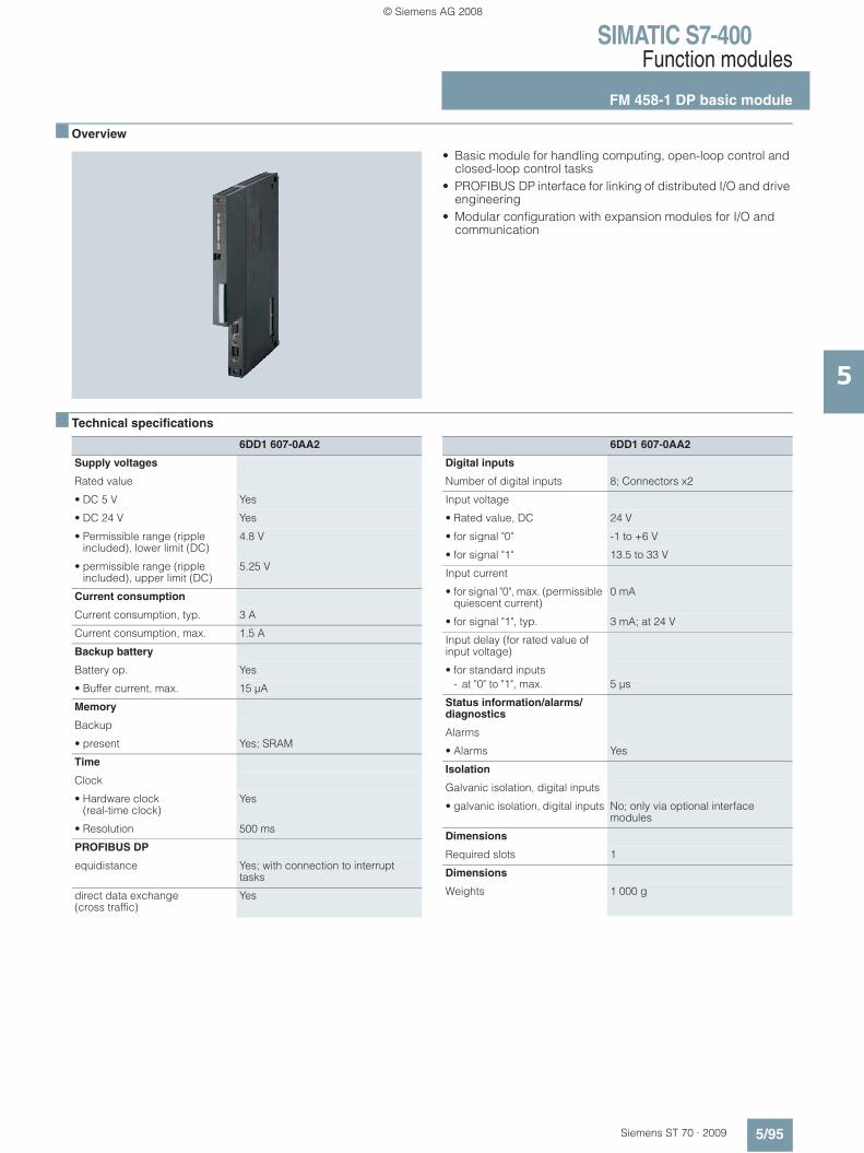
SIMATIC S7-400Function modules
FM 458-1 DP basic module
5/95Siemens ST 70 · 2009
5
■ Overview
• Basic module for handling computing, open-loop control and closed-loop control tasks
• PROFIBUS DP interface for linking of distributed I/O and drive engineering
• Modular configuration with expansion modules for I/O and communication
■ Technical specifications
6DD1 607-0AA2
Supply voltages
Rated value
• DC 5 V Yes
• DC 24 V Yes
• Permissible range (ripple included), lower limit (DC)
4.8 V
• permissible range (ripple included), upper limit (DC)
5.25 V
Current consumption
Current consumption, typ. 3 A
Current consumption, max. 1.5 A
Backup battery
Battery op. Yes
• Buffer current, max. 15 μA
Memory
Backup
• present Yes; SRAM
Time
Clock
• Hardware clock (real-time clock)
Yes
• Resolution 500 ms
PROFIBUS DP
equidistance Yes; with connection to interrupt tasks
direct data exchange (cross traffic)
Yes
6DD1 607-0AA2
Digital inputs
Number of digital inputs 8; Connectors x2
Input voltage
• Rated value, DC 24 V
• for signal "0" -1 to +6 V
• for signal "1" 13.5 to 33 V
Input current
• for signal "0", max. (permissible quiescent current)
0 mA
• for signal "1", typ. 3 mA; at 24 V
Input delay (for rated value of input voltage)
• for standard inputs- at "0" to "1", max. 5 μs
Status information/alarms/diagnostics
Alarms
• Alarms Yes
Isolation
Galvanic isolation, digital inputs
• galvanic isolation, digital inputs No; only via optional interface modules
Dimensions
Required slots 1
Dimensions
Weights 1 000 g
© Siemens AG 2008
SIMATIC S7-400Function modules
FM 458-1 DP basic module
5/96 Siemens ST 70 · 2009
5
■ Ordering data Order No. Order No.
FM 458-1 DP application module
6DD1 607-0AA2
Basic module for computing, closed-loop control and open-loop control tasks; with PROFIBUS DP interface
Micro Memory Card
for FM 458-1 DP basic module
2 MB 6ES7 953-8LL20-0AA0
4 MB 6ES7 953-8LM20-0AA0
FM 458-1 DP Know-How-Protect 6DD1 607-0GA0
for protection of technological application modules against unauthorized copying
SC 64 interface cable 6DD1 684-0GE0
To connect FM 458-1 to the serial interface of a programming device/ PC
SB10 interface module 6DD1 681-0AE2
To connect 8 binary I/Os to FM 458-1 DP
SB61 interface module 6DD1 681-0EB3
To connect 8 binary I/Os to FM 458-1 DP, input voltage: 24/48 V DC
SU12 interface module 6DD1 681-0AJ1
To connect 10 signals to FM 458-1 DP
RS 485 bus connector with 90° cable outlet
Max. transfer rate 12 Mbit/s
Without PG interface 6ES7 972-0BA12-0XA0
With PG interface 6ES7 972-0BB12-0XA0
RS 485 bus connector with angled cable outlet
Max. transfer rate 12 Mbit/s
Without PG interface 6ES7 972-0BA41-0XA0
With PG interface 6ES7 972-0BB41-0XA0
RS 485 bus connector with 90° cable outlet for FastConnect system
Max. transfer rate 12 Mbit/s
Without PG interface 6ES7 972-0BA51-0XA0
With PG interface 6ES7 972-0BB51-0XA0
PROFIBUS FastConnect bus cable
Standard type with special design for quick mounting, 2-core, shielded, sold by the meter, max. delivery unit 1000 m, minimum order quantity 20 m
6XV1 830-0EH10
Preferred lengths:
20 m 6XV1 830-0EN20
50 m 6XV1 830-0EN50
100 m 6XV1 830-0ET10
© Siemens AG 2008
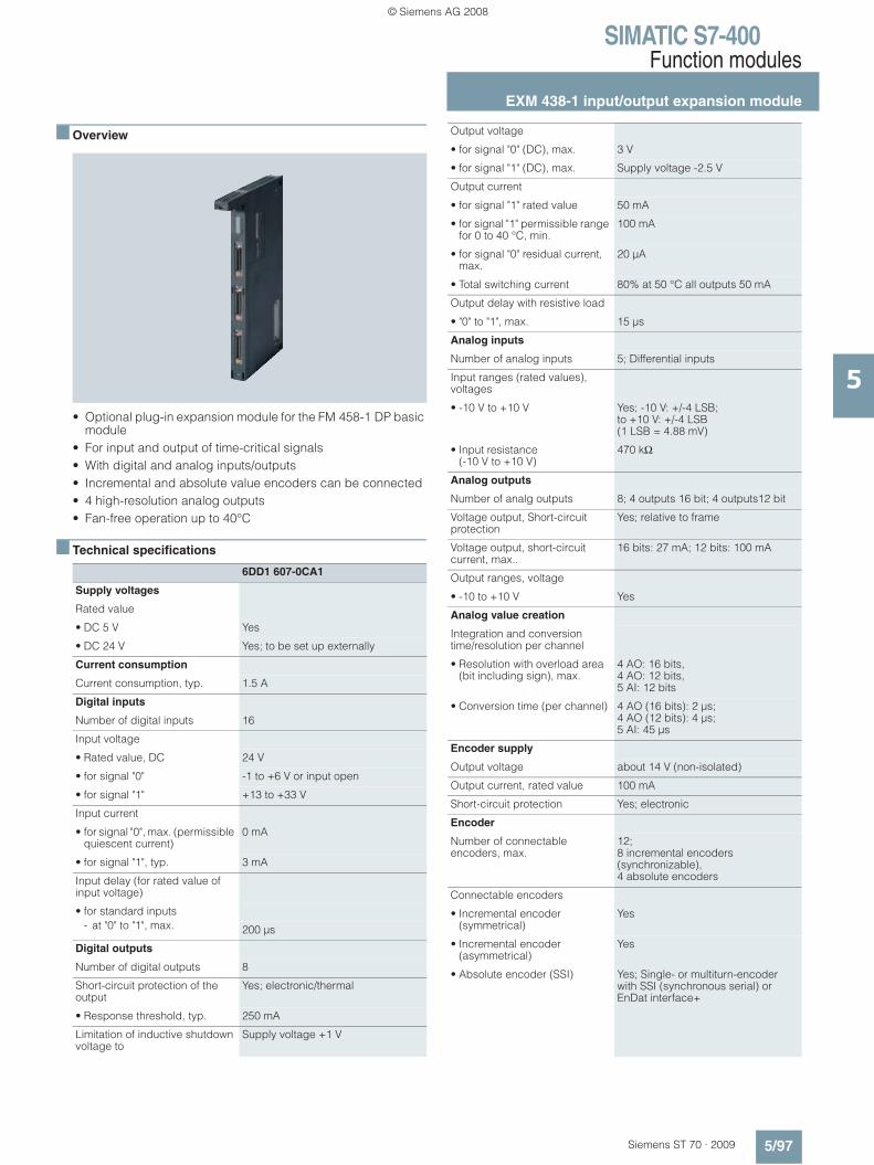
SIMATIC S7-400Function modules
EXM 438-1 input/output expansion module
5/97Siemens ST 70 · 2009
5
■ Overview
• Optional plug-in expansion module for the FM 458-1 DP basic module
• For input and output of time-critical signals• With digital and analog inputs/outputs • Incremental and absolute value encoders can be connected• 4 high-resolution analog outputs• Fan-free operation up to 40°C
■ Technical specifications
6DD1 607-0CA1
Supply voltages
Rated value
• DC 5 V Yes
• DC 24 V Yes; to be set up externally
Current consumption
Current consumption, typ. 1.5 A
Digital inputs
Number of digital inputs 16
Input voltage
• Rated value, DC 24 V
• for signal "0" -1 to +6 V or input open
• for signal "1" +13 to +33 V
Input current
• for signal "0", max. (permissible quiescent current)
0 mA
• for signal "1", typ. 3 mA
Input delay (for rated value of input voltage)
• for standard inputs- at "0" to "1", max. 200 μs
Digital outputs
Number of digital outputs 8
Short-circuit protection of the output
Yes; electronic/thermal
• Response threshold, typ. 250 mA
Limitation of inductive shutdown voltage to
Supply voltage +1 V
Output voltage
• for signal "0" (DC), max. 3 V
• for signal "1" (DC), max. Supply voltage -2.5 V
Output current
• for signal "1" rated value 50 mA
• for signal "1" permissible range for 0 to 40 °C, min.
100 mA
• for signal "0" residual current, max.
20 μA
• Total switching current 80% at 50 °C all outputs 50 mA
Output delay with resistive load
• "0" to "1", max. 15 μs
Analog inputs
Number of analog inputs 5; Differential inputs
Input ranges (rated values), voltages
• -10 V to +10 V Yes; -10 V: +/-4 LSB; to +10 V: +/-4 LSB (1 LSB = 4.88 mV)
• Input resistance(-10 V to +10 V)
470 kΩ
Analog outputs
Number of analg outputs 8; 4 outputs 16 bit; 4 outputs12 bit
Voltage output, Short-circuit protection
Yes; relative to frame
Voltage output, short-circuit current, max..
16 bits: 27 mA; 12 bits: 100 mA
Output ranges, voltage
• -10 to +10 V Yes
Analog value creation
Integration and conversion time/resolution per channel
• Resolution with overload area (bit including sign), max.
4 AO: 16 bits, 4 AO: 12 bits, 5 AI: 12 bits
• Conversion time (per channel) 4 AO (16 bits): 2 μs; 4 AO (12 bits): 4 μs; 5 AI: 45 μs
Encoder supply
Output voltage about 14 V (non-isolated)
Output current, rated value 100 mA
Short-circuit protection Yes; electronic
Encoder
Number of connectable encoders, max.
12; 8 incremental encoders (synchronizable), 4 absolute encoders
Connectable encoders
• Incremental encoder (symmetrical)
Yes
• Incremental encoder (asymmetrical)
Yes
• Absolute encoder (SSI) Yes; Single- or multiturn-encoder with SSI (synchronous serial) or EnDat interface+
© Siemens AG 2008
SIMATIC S7-400Function modules
EXM 438-1 input/output expansion module
5/98 Siemens ST 70 · 2009
5
■ Technical specifications
■ Ordering data Order No.
6DD1 607-0CA1
Encoder signals, incremental encoder (symmetrical)
• Trace mark signals 1) for tracks A and B (90° out of phase), poss. with zero pulse N; 2) for separate forward and backward track
• Input signal with 0 signal: -5 to 0 V; with 1 signal: +3 to +5 V; permissible input voltage range: differential voltage -5 to +5 V; max. input current: 15 mA (important: not limited on module side!)
• Input frequency, max. 2.5 MHz
Encoder signals, incremental encoder (asymmetrical)
• Trace mark signals Track A and B (phase-shifted by 90 degrees), possibly with zero pulse N
• Input voltage with 0 signal: -30 to +4 V (at 15 mA load); with 1 signal: +8 to 30 V (at 15 mA load); permissible input voltage range: differential voltage -30 to +30 V
• Input frequency, max. 1 MHz; Track frequency
Encoder signals, absolute encoder (SSI)
• Input signal 5 V to RS 422
• Data signal Dual-, Gray-, Gray-Excess-Code
• Clock frequency, max. 2 MHz; 100 kHz to 2 MHz (depending on cable length)
Errors/accuracies
Linearity error (relative to output area)
(+/- 1 LSB )
Isolation
Galvanic isolation, digital inputs
• galvanic isolation, digital inputs No
Isolation, digital outputs
• Galvanic isolation, digital outputs
No
Isolation, analog inputs
• Isolation, analog inputs No
Isolation, analog outputs
• Galvanic isolation, analog outputs
No
Dimensions
Required slots 1
Dimensions
Weights 1 kg
EXM 438-1 input/output expansion
6DD1 607-0CA1
for direct exchange of digital and analog signals between FM 458-1 DP and the plant
SB10 interface module 6DD1 681-0AE2
To connect 8 binary inputs or outputs to FM 458-1 DP
SB61 interface module 6DD1 681-0EB3
To connect 8 binary inputs to FM 458-1 DP, input voltage: 24/48 V DC
SB71 interface module 6DD1 681-0DH1
To connect 8 binary outputs to FM 458-1 DP, output voltage: 24/48 V DC
SU12 interface module 6DD1 681-0AJ1
To connect 10 signals to FM 458-1 DP
SU13 interface module 6DD1 681-0GK0
To connect 50 signals to FM 458-1 DP
SC 62 interface cable 6DD1 684-0GC0
To connect EXM 438-1 with up to 5 SBxx or SU12
SC 63 interface cable 6DD1 684-0GD0
To connect EXM 438-1 with an SU13
© Siemens AG 2008

SIMATIC S7-400Function modules
EXM 448universal communication expansion module
5/99Siemens ST 70 · 2009
5
■ Overview
• Optional expansion module for the FM 458-1 DP basic module
• For fast communication over PROFIBUS DP or SIMOLINK• EXM 448: With vacant slot for a MASTERDRIVES option
module
■ Technical specifications
■ Ordering data Order No.
6DD1 607-0EA0
Supply voltages
Rated value
• DC 5 V Yes
Current consumption
Current consumption, typ. 0.8 A
Dimensions
Required slots 1
Dimensions
Weights 0.8 kg
EXM 448 universal communications expansion module
6DD1 607-0EA0
For fast communication, for example, with drives; with free slot for MASTERDRIVES option module
© Siemens AG 2008
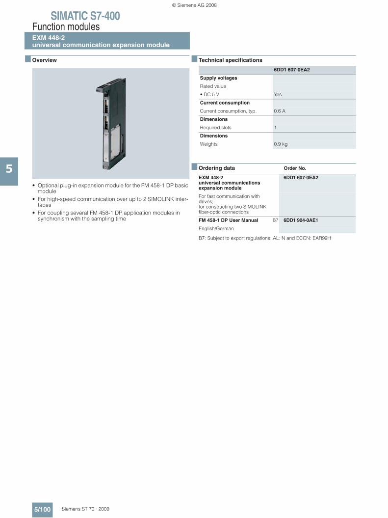
SIMATIC S7-400Function modulesEXM 448-2 universal communication expansion module
5/100 Siemens ST 70 · 2009
5
■ Overview
• Optional plug-in expansion module for the FM 458-1 DP basic module
• For high-speed communication over up to 2 SIMOLINK inter-faces
• For coupling several FM 458-1 DP application modules in synchronism with the sampling time
■ Technical specifications
■ Ordering data Order No.
B7: Subject to export regulations: AL: N and ECCN: EAR99H
6DD1 607-0EA2
Supply voltages
Rated value
• DC 5 V Yes
Current consumption
Current consumption, typ. 0.6 A
Dimensions
Required slots 1
Dimensions
Weights 0.9 kg
EXM 448-2 universal communications expansion module
6DD1 607-0EA2
For fast communication with drives; for constructing two SIMOLINK fiber-optic connections
FM 458-1 DP User Manual B7 6DD1 904-0AE1
English/German
© Siemens AG 2008

SIMATIC S7-400Function modules
Accessories for FM 458-1 DP
5/101Siemens ST 70 · 2009
5
■ Overview SC64 interface cable
• For connecting the FM 458-1 DP to an SBxx or SU12 interface module
• To use the digital inputs of the FM 458-1 DP with interrupt capability
■ Overview SC62 interface cable
This cable is used to connect the SIMATIC TDC SM500 peripheral module (I/O) or the SIMATIC S7-400 EXM 438-1 expansion module to up to 5 interface modules SB10, SB60, SB70, SB61 SB71 and/ or SU12.
■ Overview SC63 interface cable
This cable is used to connect the SIMATIC TDC SM500 peripheral (I/O) module or the SIMATIC S7-400 EXM 438-1 expansion module to a SU13 interface module.
■ Overview SB10 interface module
The interface module is used to connect 8 digital inputs or outputs.
© Siemens AG 2008
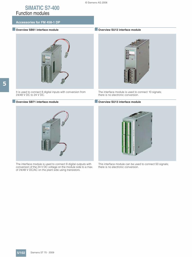
SIMATIC S7-400Function modules
Accessories for FM 458-1 DP
5/102 Siemens ST 70 · 2009
5
■ Overview SB61 interface module
It is used to connect 8 digital inputs with conversion from 24/48 V DC to 24 V DC.
■ Overview SB71 interface module
The interface module is used to connect 8 digital outputs with conversion of the 24 V DC voltage on the module side to a max. of 24/48 V DC/AC on the plant side using transistors.
■ Overview SU12 interface module
The interface module is used to connect 10 signals; there is no electronic conversion.
■ Overview SU13 interface module
This interface module can be used to connect 50 signals; there is no electronic conversion.
© Siemens AG 2008

SIMATIC S7-400Function modules
Accessories for FM 458-1 DP
5/103Siemens ST 70 · 2009
5
■ Technical specifications
■ Ordering data Order No.
Technical specifications SB10 interface module
Number of digital inputs or outputs 8
Electrical isolation No
Max. cable cross-section 1.5 mm²
Dimensions (W x H x D) in mm 45 x 130 x 156
Weight 0.3 kg
Technical specifications SB61 interface module
Number of digital inputs for 8
• Input voltage DC 24/48 V
Electrical isolation Yes, via optocoupler
Max. cable cross-section 1.5 mm²
Dimensions (W x H x D) in mm 45 x 130 x 156
Weight 0.32 kg
Technical specifications SB71 interface module
Number of digital outputs 8
• Output voltage, max 24/48 V DC
Output current, max. 40 mA, short-circuit proof
Electrical isolation Yes, via optocoupler
Max. cable cross-section 1.5 mm²
Dimensions (W x H x D) in mm 45 x 130 x 156
Weight 0.32 kg
Technical specifications SU12 interface module
Number of signal cables which can be connected
10
Signal amplitude per signal, max. 60 V. 0.5 A
Electrical isolation No
Max. cable cross-section 1.5 mm²
Dimensions (W x H x D) in mm 45 x 130 x 156
Weight 0.28 kg
Technical specifications SU13 interface module
Number of signal cables which can be connected
50
Signal amplitude per signal, max. 60 V, 0.5 A
Electrical isolation No
Max. cable cross-section 1.5 mm²
Dimensions (W x H x D) in mm 45 x 130 x 156
Weight 0.3 kg
SC 64 interface cable 6DD1 684-0GE0
for connection of FM 458-1 to the serial port of a PG/PC
SC62 interface cable 6DD1 684-0GC0
between the SM500 or EXM 438-1 module and a max. of 5 interface moduls SB10, SB60, SB70, SB61, SB71 and/or SU12, 2 m long
SC63 interface cable 6DD1 684-0GD0
between an SM500 or EXM 438-1 module and SU13 interface module, 2 m long
SB10 interface module 6DD1 681-0AE2
8 digital inputs/outputs, 24 V DC
SB61 interface module 6DD1 681-0EB3
8 digital inputs, 24/48 V DC
SB71 interface module 6DD1 681-0DH1
8 digital outputs with transistors, 24/48 V DC
SU12 interface module 6DD1 681-0AJ1
with plug-in terminal, 10-pin
SU13 interface module 6DD1 681-0GK0
with screw-plug-in terminal
© Siemens AG 2008

SIMATIC S7-400Function modules
SIPLUS DCF 77 radio clock module
5/104 Siemens ST 70 · 2009
5
■ Overview
This module can be used to synchronize the real-time clock of the SIMATIC S7-200, S7-300 and S7-400 automation systems with the official time of the DCF 77 time signal transmitter of the Physikalisch-Technische Bundesanstalt Braunschweig.
The time is received by means of a DCF receiver (antenna with electronics) which is connected via two digital inputs on the SIMATIC and SIPLUS together with a software driver included in the scope of delivery (function block FB). The function blocks are available on the Internet for downloading.
http://www.siemens.com/siplus – Support – Tools and Downloads!
■ Technical specifications
1) Additionally 25 mm (0.98 in) for heavy duty threaded joint and bending radius for cables
■ Ordering data Order No.
B7: Subject to export regulations: AL: N and ECCN: EAR99H
Radio clock module SIPLUS DCF 77
Radio frequency 77.5 Hz
Power supply DC 24 V (DC 20.4 ... 28. 8)
Power consumption, typ. 50 mA
Dimensions (W x H x D) 75 x 125 1) x 75
SIPLUS DCF 77 radio clock module
B7 6AG1 057-1AA03-0AA0
For synchronizing SIMATIC S7-200, S7-300 and S7-400 with the official time of the DCF 77 time signal transmitter of the Physikalisch-Technische Bunde-sanstalt Braunschweig
© Siemens AG 2008

SIMATIC S7-400Communication
CP 440
5/105Siemens ST 70 · 2009
5
■ Overview
• For high-performance transmission of messages via point-to-point connections (high message rate)
• Physical interface: RS 422/RS 485 (X.27)• Up to 32 nodes• Protocol implemented: ASCII, 3964 (R)• Simple parameterization via a parameterization tool integrated
into STEP 7
■ Technical specifications
■ Ordering data Order No.
6ES7 440-1CS00-0YE0
Supply voltages
Rated value
• DC 5 V Yes
• DC 24 V Yes
Current consumption
from backplane bus DC 5 V, max.
360 mA
Current consumption/power loss Power loss, typ. 1.7 W
Memory
Type of storage
Memory requirements per interface in CompactFlash Card of S7-CPU
1 to 5 Kbytes for parameters
interfaces
Number of interfaces 1
interface physics, RS 422/RS 485 (X.27)
Yes
RS 422/485, cable length, shielded, max.
1 200 m
Point-to-point
Integrated protocol driver
• 3964 (R) Yes
• ASCII Yes
Transmission speed, RS 422/485
• with 3964 (R) protocol, max. 115.2 kBit/s
• with ASCII protocol, max. 115.2 kBit/s
CPU/programming
Configuration software
• STEP 7 Yes; own parameter assignment forms
Dimensions
Dimensions
• Width 25 mm
• Height 290 mm
• Depth 210 mm
Weights
• Weight, approx. 600 g
CP 440 communications processor
6ES7 440-1CS00-0YE0
with one RS 422/485 (X.27) interface
RS 422/485 connecting cable
for linking to SIMATIC S7
5 m 6ES7 902-3AB00-0AA0
10 m 6ES7 902-3AC00-0AA0
50 m 6ES7 902-3AG00-0AA0
© Siemens AG 2008
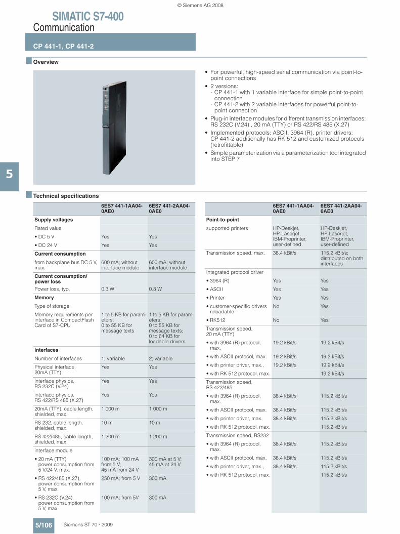
SIMATIC S7-400Communication
CP 441-1, CP 441-2
5/106 Siemens ST 70 · 2009
5
■ Overview
• For powerful, high-speed serial communication via point-to-point connections
• 2 versions: - CP 441-1 with 1 variable interface for simple point-to-point
connection - CP 441-2 with 2 variable interfaces for powerful point-to-
point connection• Plug-in interface modules for different transmission interfaces:
RS 232C (V.24) , 20 mA (TTY) or RS 422/RS 485 (X.27)• Implemented protocols: ASCII, 3964 (R), printer drivers;
CP 441-2 additionally has RK 512 and customized protocols (retrofittable)
• Simple parameterization via a parameterization tool integrated into STEP 7
■ Technical specifications
6ES7 441-1AA04-0AE0
6ES7 441-2AA04-0AE0
Supply voltages
Rated value
• DC 5 V Yes Yes
• DC 24 V Yes Yes
Current consumption
from backplane bus DC 5 V, max.
600 mA; without interface module
600 mA; without interface module
Current consumption/power lossPower loss, typ. 0.3 W 0.3 W
Memory
Type of storage
Memory requirements per interface in CompactFlash Card of S7-CPU
1 to 5 KB for param-eters; 0 to 55 KB for message texts
1 to 5 KB for param-eters; 0 to 55 KB for message texts; 0 to 64 KB for loadable drivers
interfaces
Number of interfaces 1; variable 2; variable
Physical interface, 20mA (TTY)
Yes Yes
interface physics, RS 232C (V.24)
Yes Yes
interface physics, RS 422/RS 485 (X.27)
Yes Yes
20mA (TTY), cable length, shielded, max.
1 000 m 1 000 m
RS 232, cable length, shielded, max.
10 m 10 m
RS 422/485, cable length, shielded, max.
1 200 m 1 200 m
interface module
• 20 mA (TTY), power consumption from 5 V/24 V, max.
100 mA; 100 mA from 5 V; 45 mA from 24 V
300 mA at 5 V; 45 mA at 24 V
• RS 422/485 (X.27), power consumption from 5 V, max.
250 mA; from 5 V 300 mA
• RS 232C (V.24), power consumption from 5 V, max.
100 mA; from 5V 300 mA
6ES7 441-1AA04-0AE0
6ES7 441-2AA04-0AE0
Point-to-point
supported printers HP-Deskjet, HP-Laserjet, IBM-Proprinter, user-defined
HP-Deskjet, HP-Laserjet, IBM-Proprinter, user-defined
Transmission speed, max. 38.4 kBit/s 115.2 kBit/s; distributed on both interfaces
Integrated protocol driver
• 3964 (R) Yes Yes
• ASCII Yes Yes
• Printer Yes Yes
• customer-specific drivers reloadable
No Yes
• RK512 No Yes
Transmission speed, 20 mA (TTY)
• with 3964 (R) protocol, max.
19.2 kBit/s 19.2 kBit/s
• with ASCII protocol, max. 19.2 kBit/s 19.2 kBit/s
• with printer driver, max., 19.2 kBit/s 19.2 kBit/s
• with RK 512 protocol, max. 19.2 kBit/s
Transmission speed, RS 422/485
• with 3964 (R) protocol, max.
38.4 kBit/s 115.2 kBit/s
• with ASCII protocol, max. 38.4 kBit/s 115.2 kBit/s
• with printer driver, max. 38.4 kBit/s 115.2 kBit/s
• with RK 512 protocol, max. 115.2 kBit/s
Transmission speed, RS232
• with 3964 (R) protocol, max.
38.4 kBit/s 115.2 kBit/s
• with ASCII protocol, max. 38.4 kBit/s 115.2 kBit/s
• with printer driver, max., 38.4 kBit/s 115.2 kBit/s
• with RK 512 protocol, max. 115.2 kBit/s
© Siemens AG 2008
SIMATIC S7-400Communication
CP 441-1, CP 441-2
5/107Siemens ST 70 · 2009
5
■ Technical specifications (continued)
■ Ordering data Order No. Order No.
6ES7 441-1AA04-0AE0
6ES7 441-2AA04-0AE0
CPU/programming
Configuration software
• STEP 7 Yes; own parameter assignment forms
Yes; own parameter assignment forms
6ES7 441-1AA04-0AE0
6ES7 441-2AA04-0AE0
Dimensions
Dimensions
• Width 25 mm 25 mm
• Height 290 mm 290 mm
• Depth 210 mm 210 mm
Weights
• Weight, approx. 800 g; Interface module: 100 g
720 g; Interface module: 100 g
CP 441-1 communications processor
6ES7 441-1AA04-0AE0
With 1 variable interface for interface submodules; including configuration package on CD
CP 441-2 communications processor
6ES7 441-2AA04-0AE0
With 2 variable interfaces for interface submodules; including configuration package on CD
Interface submodules
RS 232C (V.24) 6ES7 963-1AA00-0AA0
20 mA (TTY) 6ES7 963-2AA00-0AA0
RS 422/485 (X.27) 6ES7 963-3AA00-0AA0
RS 232 connecting cable
5 m 6ES7 902-1AB00-0AA0
10 m 6ES7 902-1AC00-0AA0
TTY connecting cable
5 m 6ES7 902-2AB00-0AA0
10 m 6ES7 902-2AC00-0AA0
50 m 6ES7 902-2AG00-0AA0
RS 422/485 connecting cable
5 m 6ES7 902-3AB00-0AA0
10 m 6ES7 902-3AC00-0AA0
50 m 6ES7 902-3AG00-0AA0
Loadable drivers for CP 441-2
MODBUS master (RTU format)
• Single license 6ES7 870-1AA01-0YA0
• Single license, without software or documentation
6ES7 870-1AA01-0YA1
MODBUS slave (RTU format)
• Single license 6ES7 870-1AB01-0YA0
• Single license, without software or documentation
6ES7 870-1AB01-0YA1
Data highway (DF1 protocol)
• Single license 6ES7 870-1AE00-0YA0
• Single license, without software or documentation
6ES7 870-1AE00-0YA1
© Siemens AG 2008
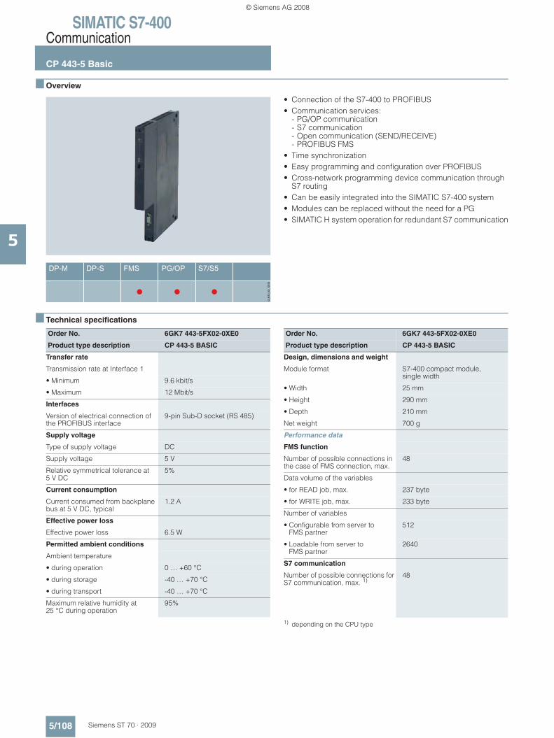
SIMATIC S7-400Communication
CP 443-5 Basic
5/108 Siemens ST 70 · 2009
5
■ Overview
• Connection of the S7-400 to PROFIBUS• Communication services:
- PG/OP communication- S7 communication- Open communication (SEND/RECEIVE)- PROFIBUS FMS
• Time synchronization• Easy programming and configuration over PROFIBUS• Cross-network programming device communication through
S7 routing• Can be easily integrated into the SIMATIC S7-400 system• Modules can be replaced without the need for a PG• SIMATIC H system operation for redundant S7 communication
■ Technical specifications
1) depending on the CPU type
Order No. 6GK7 443-5FX02-0XE0
Product type description CP 443-5 BASIC
Transfer rate
Transmission rate at Interface 1
• Minimum 9.6 kbit/s
• Maximum 12 Mbit/s
Interfaces
Version of electrical connection of the PROFIBUS interface
9-pin Sub-D socket (RS 485)
Supply voltage
Type of supply voltage DC
Supply voltage 5 V
Relative symmetrical tolerance at 5 V DC
5%
Current consumption
Current consumed from backplane bus at 5 V DC, typical
1.2 A
Effective power loss
Effective power loss 6.5 W
Permitted ambient conditions
Ambient temperature
• during operation 0 … +60 °C
• during storage -40 … +70 °C
• during transport -40 … +70 °C
Maximum relative humidity at 25 °C during operation
95%
Order No. 6GK7 443-5FX02-0XE0
Product type description CP 443-5 BASIC
Design, dimensions and weight
Module format S7-400 compact module, single width
• Width 25 mm
• Height 290 mm
• Depth 210 mm
Net weight 700 g
Performance data
FMS function
Number of possible connections in the case of FMS connection, max.
48
Data volume of the variables
• for READ job, max. 237 byte
• for WRITE job, max. 233 byte
Number of variables
• Configurable from server to FMS partner
512
• Loadable from server to FMS partner
2640
S7 communication
Number of possible connections for S7 communication, max. 1)
48
© Siemens AG 2008
SIMATIC S7-400Communication
CP 443-5 Basic
5/109Siemens ST 70 · 2009
5
■ Technical specifications (continued)
2) also S5-compatible communication
■ Ordering data Order No. Order No.
Order No. 6GK7 443-5FX02-0XE0
Product type description CP 443-5 BASIC
Open communication
Number of possible connections for open communication by means of SEND/RECEIVE blocks, max. 2)
32
Data volume as useful data for open communication (SEND/RECEIVE) per connection, max.
240 bytes
Order No. 6GK7 443-5FX02-0XE0
Product type description CP 443-5 BASIC
Multi-protocol operation
Number of possible connections, of which 2 reserved for PG/OP communication in the case of multi-protocol operation, max.
59
CP 443-5 communications processor
6GK7 443-5FX02-0XE0
Communications processor for connection of S7-400 to PROFIBUS, FMS, open communi-cation, PG/OP and S7 communi-cation; with electronic manual on CD-ROM
STEP 7 Version 5.4
Target system: SIMATIC S7-300/-400, SIMATIC C7, SIMATIC WinAC Requirement: Windows 2000 Prof./XP Prof. Delivery package: German, English, French, Spanish, Italian; incl. 3.5" authori-zation diskette, without documen-tation
• Floating license on CD 6ES7 810-4CC08-0YA5
• Rental license for 50 hours 6ES7 810-4CC08-0YA6
• Software Update Service on CD (requires current software version)
6ES7 810-4BC01-0YX2
• Upgrade Floating License 3.x/4.x/5.x to V5.4; on CD
6ES7 810-4CC08-0YE5
• Trial License STEP 7 V5.4; on CD, runs for 14 days
6ES7 810-4CC08-0YA7
PROFIBUS FastConnect bus connector RS485
With 90° cable outlet; insulation displacement technology, max. transmission rate 12 Mbit/s
• without PG interface 6ES7 972-0BA51-0XA0
• with PG interface 6ES7 972-0BB51-0XA0
PROFIBUS bus connector IP20
With connection to PPI, MPI, PROFIBUS
• without PG interface 6ES7 972-0BA12-0XA0
• with PG interface 6ES7 972-0BB12-0XA0
PROFIBUS bus terminal 12M 6GK1 500-0AA10
Bus terminal for connection of PROFIBUS stations up to 12 Mbit/s with plug-in cable
© Siemens AG 2008

SIMATIC S7-400Communication
CP 443-5 Extended
5/110 Siemens ST 70 · 2009
5
■ Overview
• DP-V1 master connection of the S7-400 to PROFIBUS• For setting up additional PROFIBUS DP lines• Communication services:
- PROFIBUS DP- PG/OP communication- S7 communication- Open communication (SEND/RECEIVE)
• Time synchronization• Easy programming and configuration over PROFIBUS• Cross-network programming device communication through
S7 routing• Can be easily integrated into the SIMATIC S7-400 system• Module replacement without PG• SIMATIC H system operation for redundant S7 communication
or DP-Master communication• Data record routing (PROFIBUS DP)• Adding or modifying distributed I/O during operation
■ Technical specifications
Order No. 6GK7 443-5DX04-0XE0
Product type description CP 443-5 Extended
Transfer rate
Transmission rate at Interface 1• Minimum 9.6 kbit/s• Maximum 12 Mbit/s
Interfaces
Version of electrical connection of the PROFIBUS interface
9-pin Sub-D socket (RS 485)
Supply voltage
Type of supply voltage DC
Supply voltage 5 V
Relative symmetrical tolerance at 5 V DC
5%
Current consumption
Current consumed from backplane bus at 5 V DC, typical
1.3 A
Effective power loss
Effective power loss 6.5 W
Permitted ambient conditions
Ambient temperature• during operation 0 … +60 °C• during storage -40 … +70 °C• during transport -40 … +70 °C
Maximum relative humidity at 25 °C during operation
95%
Order No. 6GK7 443-5DX04-0XE0
Product type description CP 443-5 Extended
Design, dimensions and weight
Module format S7-400 compact module, single width
• Width 25 mm• Height 290 mm• Depth 210 mm
Net weight 700 g
Max. number of modules per CPU 14
Number of external DP lines per central rack, max.
10
Performance data
PROFIBUS DP
Service as DP-Master DPV1 Yes
Number of DP-Slaves operable on DP-Master
125
Data volume• of the address area of the inputs
as DP-Master overall4 Kibyte
• of the address area of the outputs as DP-Master overall
4 Kibyte
• of the address area of the inputs per DP-Slave
244 bytes
• of the address area of the outputs per DP-Slave
244 bytes
© Siemens AG 2008
SIMATIC S7-400Communication
CP 443-5 Extended
5/111Siemens ST 70 · 2009
5
■ Technical specifications (continued)
1) depending on the CPU type2) also S5-compatible communication
■ Ordering data Order No. Order No.
Order No. 6GK7 443-5DX04-0XE0
Product type description CP 443-5 Extended
S7 communication
Number of possible connections for S7 communication, max.
48 1)
Open communication
Number of possible connections for open communication by means of SEND/RECEIVE blocks, max. 2)
32
Data volume as useful data for open communication (SEND/RECEIVE) per connection, max.
240 bytes
Order No. 6GK7 443-5DX04-0XE0
Product type description CP 443-5 Extended
Multi-protocol operation
Number of active connections in multi-protocol operation• without DP, max. 59• with DP, max. 55
CP 443-5 Extended communications processor
6GK7 443-5DX04-0XE0
for connection of the SIMATIC S7-400 to PROFIBUS,Extended version for PROFIBUS DP; with electronic manual on CD-ROM
STEP 7 Version 5.4
Target system: SIMATIC S7-300/-400, SIMATIC C7, SIMATIC WinAC Requirement: Windows 2000 Prof./XP Prof. Delivery package: German, English, French, Spanish, Italian; incl. 3.5" authori-zation diskette, without documen-tation
• Floating license on CD 6ES7 810-4CC08-0YA5
• Rental license for 50 hours 6ES7 810-4CC08-0YA6
• Software Update Service on CD (requires current software version)
6ES7 810-4BC01-0YX2
• Upgrade Floating License 3.x/4.x/5.x to V5.4; on CD
6ES7 810-4CC08-0YE5
• Trial License STEP 7 V5.4; on CD, runs for 14 days
6ES7 810-4CC08-0YA7
PROFIBUS FastConnect bus connector RS485
With 90° cable outlet; insulation displacement technology, max. transmission rate 12 Mbit/s
• without PG interface 6ES7 972-0BA51-0XA0
• with PG interface 6ES7 972-0BB51-0XA0
PROFIBUS bus connector IP20
With connection to PPI, MPI, PROFIBUS
• without PG interface 6ES7 972-0BA12-0XA0
• with PG interface 6ES7 972-0BB12-0XA0
PROFIBUS bus terminal 12M 6GK1 500-0AA10
Bus terminal for connection of PROFIBUS nodes at up to 12 Mbit/s with connecting cable
© Siemens AG 2008

SIMATIC S7-400Communication
CP 443-1
5/112 Siemens ST 70 · 2009
5
■ Overview
• Connection of SIMATIC S7-400 to Industrial Ethernet - 2 x RJ45 interface for 10/100 Mbit/s full/half duplex
connection with autosensing/autonegotiation and autocrossover function
- Integrated real-time switch ERTEC with two ports- Multi-protocol operation for ISO, TCP/IP, UDP and PROFINET
IO protocols- Adjustable Keep Alive function
• Communication services: - Open communication (ISO, TCP/IP and UDP)- PROFINET IO Controller with real-time properties RT and IRT- PG/OP communication: Across networks by means of S7
routing- S7 communication
• Multicast for UDP• Access protection by means of configurable access list• Support for fail-safe programmable controllers in combination
with SIMATIC S7-400 CPU 416F-3 PN/DP• Module replacement without PG• SIMATIC H system operation for redundant S7 communication• Configuration with STEP 7• Diagnostic possibilities in STEP 7 and with web browser• Automatic setting of the CPU clock by means of Industrial
Ethernet with NTP or SIMATIC procedure• Integration of network management systems via SNMP
(MIB II diagnostic information)
© Siemens AG 2008

SIMATIC S7-400Communication
CP 443-1
5/113Siemens ST 70 · 2009
5
■ Technical specifications
1) when using several CPUs2) depending on the CPU type3) also S5-compatible communication
Order No. 6GK7 443-1EX20-0XE0
Product type description CP 443-1
Transfer rate
Transmission rate at Interface 1
• Minimum 10 Mbit/s
• Maximum 100 Mbit/s
Interfaces
Version of electrical connection to the Industrial Ethernet interface 1
2 x RJ45 (TP)
Supply voltage
Type of supply voltage DC
Supply voltage 5 V
Relative symmetrical tolerance at 5 V DC
5%
Current consumption
Current consumed from backplane bus at 5 V DC, typical
1.4 A
Effective power loss
Effective power loss 8.6 W
Permitted ambient conditions
Ambient temperature
• during operation 0 … +60 °C
• during storage -40 … +70 °C
• during transport -40 … +70 °C
Maximum relative humidity at 25 °C during operation
95%
Design, dimensions and weight
Module format S7-400 compact module, single width
• Width 25 mm
• Height 290 mm
• Depth 210 mm
Net weight 700 g
Order No. 6GK7 443-1EX20-0XE0
Product type description CP 443-1
Performance data
Open communication
Number of possible connections for open communication by means of SEND/RECEIVE blocks, max. 3)
64 2)
Data volume as useful data for open communication by means of SEND/RECEIVE blocks
• per ISO connection, max. 8 KB
• per ISO on TCP connection, max. 8 KB
• per TCP connection, max. 8 KB
• per UDP connection, max. 2 KB
Number of possible connections for open communication by means T blocks, max.
64
Data volume as useful data for open communication by means T-blocks
• per ISO on TCP connection, max. 1 452 bytes
S7 communication
Number of possible connections for S7 communication
• Maximum 128 1)
• for PG connections, maximum 2
• for OP connections, maximum 30
Multi-protocol operation
Number of active connections in multi-protocol operation
128
Performance data, PROFINET communication as PN IO controller
Number of PN IO devices operable on PROFINET IO controller
128
Number of external PN IO lines with PROFINET per subrack
4
of which, PN IO IRT devices 32
Data volume
• as useful data for input variables as PROFINET IO controller
4 KB
• as useful data for output variables as PROFINET IO controller
4 KB
• as useful data for input variables per PN IO device as PROFINET IO controller
240 bytes
• as useful data for output variables per PN IO device as PROFINET IO controller
240 bytes
Configuration
Configuration software for full functional scope STEP 7 V5.4 SP4 or higher
Yes
© Siemens AG 2008
SIMATIC S7-400Communication
CP 443-1
5/114 Siemens ST 70 · 2009
5
■ Ordering data Order No. Order No.
A8: Subject to export regulations: AL: N and ECCN: 5A991XB3: Subject to export regulations: AL: N and ECCN: 5D992B1
CP 443-1 communications processor
A8 6GK7 443-1EX20-0XE0
For connecting SIMATIC S7-400 to Industrial Ethernet through TCP/IP, ISO and UDP; PROFINET IO Controller, integrated real-time switch ERTEC with two ports; 2 x RJ45 interface; S7 communi-cation, open communication (SEND/RECEIVE) with FETCH/WRITE, with and without RFC 1006, DHCP, SNMP V2, diagnostics, multicast, access protection over IP access list, initialization over LAN 10/100 Mbit/s with electronic manual on DVD
IE FC TP Standard Cable GP 2x2 6XV1 840-2AH104-core, shielded TP installation cable for connection to IE FC Outlet RJ45/ IE FC RJ45 Plug; PROFINET-compatible; with UL approval; sold by the meter
FO Standard Cable GP (50/125) 6XV1 873-2AStandard cable, splittable, UL approval, sold by the meter
SCALANCE X204-2 Industrial Ethernet switch
6GK5 204-2BB10-2AA3
Industrial Ethernet switches with integral SNMP access, online diagnostics, copper cable diagnostics and PROFINET diagnostics for configuring line, star and ring topologies; four 10/100 Mbit/s RJ45 ports and two FO ports
IE FC RJ45 Plug 180RJ45 plug connector for Industrial Ethernet with a rugged metal housing and integrated insulation displacement contacts for connecting Industrial Ethernet FC installation cables; with 180° cable outlet; for network compo-nents and CPs/CPUs with Industrial Ethernet interface• 1 pack = 1 unit 6GK1 901-1BB10-2AA0
• 1 pack = 10 units 6GK1 901-1BB10-2AB0
• 1 pack = 50 units 6GK1 901-1BB10-2AE0
SOFTNET Edition 2007 for Industrial EthernetSoftware for S7 and open commu-nication, incl. OPC server, PG/OP communication and NCM PC, runtime software, software and electronic manual on CD-ROM, license key on USB stick, Class A, for 32-bit Windows XP Profes-sional SP1, 2, Windows 2003 Server SP1, R2, SP2, Windows Vista Business/Ultimate; German/English
SOFTNET-S7 Edition 2007 for Industrial Ethernetup to 64 connections• Single license for 1 installation B3 6GK1 704-1CW70-3AA0• Software Update Service
for 1 year, with automatic extension; requirement: Current software version
6GK1 704-1CW00-3AL0
• Upgrade from V6.4to 2007 edition
B3 6GK1 704-1CW00-3AE0
• Upgrade from V6.0, V6.1, V6.2 or V6.3 to 2007 Edition
B3 6GK1 704-1CW00-3AE1
SOFTNET-S7 Lean Edition 2007 for Industrial Ethernet
up to 8 connections
• Single license for 1 installation B3 6GK1 704-1LW70-3AA0
• Software Update Servicefor 1 year, with automatic extension; requirement: Current software version
6GK1 704-1LW00-3AL0
• Upgrade from V6.4 to 2007 Edition
B3 6GK1 704-1LW00-3AE0
• Upgrade from V6.0, V6.1, V6.2 or V6.3 to 2007 Edition
B3 6GK1 704-1LW00-3AE1
S7-1613 Edition 2007
Software for S7 and open commu-nication, incl. PG/OP communi-cation, OPC server and NCM PC; up to 120 connections, runtime software, software and electronic manual on CD-ROM, license key on USB stick, Class A, for 32-bit Windows XP Professional SP1, 2; Windows 2003 Server SP1, R2, SP2, Windows Vista Business/Ultimate; for CP 1613/CP 1613 A2/CP 1623; German/English
• Single license for 1 installation B3 6GK1 716-1CB70-3AA0
• Software Update Servicefor 1 year, with automatic extension; requirement: Current software version
6GK1 716-1CB00-3AL0
• Upgrade S7-1613 from V6.4 to 2007 Edition
B3 6GK1 716-1CB00-3AE0
• Upgrade S7-1613 from V6.0, V6.1, V6.2 or V6.3 to S7-1613 Edition 2007
B3 6GK1 716-1CB00-3AE1
STEP 7 Version 5.4
Target system: SIMATIC S7-300/-400, SIMATIC C7, SIMATIC WinAC Requirement: Windows 2000 Prof./XP Prof. Delivery package: German, English, French, Spanish, Italian; incl. 3.5" authorization diskette, without documentation
• Floating license on CD 6ES7 810-4CC08-0YA5
• Rental license for 50 hours 6ES7 810-4CC08-0YA6
• Software Update Service on CD (requires current software version)
6ES7 810-4BC01-0YX2
• Upgrade Floating License 3.x/4.x/5.x to V5.4; on CD
6ES7 810-4CC08-0YE5
• Trial License STEP 7 V5.4; on CD, runs for 14 days
6ES7 810-4CC08-0YA7
© Siemens AG 2008
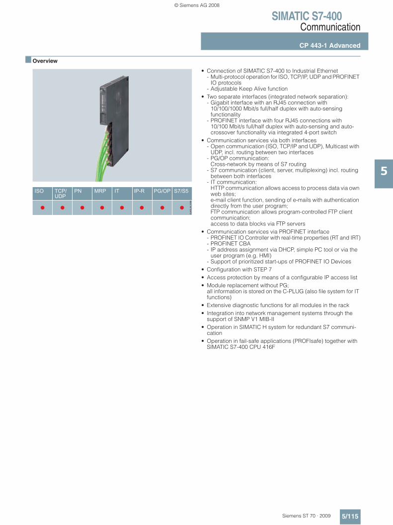
SIMATIC S7-400Communication
CP 443-1 Advanced
5/115Siemens ST 70 · 2009
5
■ Overview
• Connection of SIMATIC S7-400 to Industrial Ethernet - Multi-protocol operation for ISO, TCP/IP, UDP and PROFINET
IO protocols- Adjustable Keep Alive function
• Two separate interfaces (integrated network separation): - Gigabit interface with an RJ45 connection with
10/100/1000 Mbit/s full/half duplex with auto-sensing functionality
- PROFINET interface with four RJ45 connections with 10/100 Mbit/s full/half duplex with auto-sensing and auto-crossover functionality via integrated 4-port switch
• Communication services via both interfaces - Open communication (ISO, TCP/IP and UDP), Multicast with
UDP, incl. routing between two interfaces- PG/OP communication:
Cross-network by means of S7 routing- S7 communication (client, server, multiplexing) incl. routing
between both interfaces- IT communication:
HTTP communication allows access to process data via own web sites; e-mail client function, sending of e-mails with authentication directly from the user program; FTP communication allows program-controlled FTP client communication; access to data blocks via FTP servers
• Communication services via PROFINET interface - PROFINET IO Controller with real-time properties (RT and IRT)- PROFINET CBA- IP address assignment via DHCP, simple PC tool or via the
user program (e.g. HMI)- Support of prioritized start-ups of PROFINET IO Devices
• Configuration with STEP 7• Access protection by means of a configurable IP access list• Module replacement without PG;
all information is stored on the C-PLUG (also file system for IT functions)
• Extensive diagnostic functions for all modules in the rack• Integration into network management systems through the
support of SNMP V1 MIB-II• Operation in SIMATIC H system for redundant S7 communi-
cation• Operation in fail-safe applications (PROFIsafe) together with
SIMATIC S7-400 CPU 416F
© Siemens AG 2008
SIMATIC S7-400Communication
CP 443-1 Advanced
5/116 Siemens ST 70 · 2009
5
■ Technical specifications
1) also S5-compatible communication2) depending on the CPU type
Order No. 6GK7 443-1GX20-0XE0
Product type description CP 443-1 Advanced
Transfer rate
Transmission rate at Interface 1
• Minimum 10 Mbit/s
• Maximum 1000 Mbit/s
Transmission rate at Interface 2
• Minimum 10 Mbit/s
• Maximum 100 Mbit/s
Interfaces
Electrical connection version
• at Industrial Ethernet interface 1 1 x RJ45 (TP)
• at Industrial Ethernet interface 2 4 x RJ45 (TP)
Slot version of the swap medium C-PLUG
Supply voltage
Type of supply voltage DC
Supply voltage 5 V
Relative symmetrical tolerance at 5 V DC
5%
Current consumption
Current consumed from backplane bus at 5 V DC, typical
1.34 A
Effective power loss
Effective power loss 7.25 W
Permitted ambient conditions
Ambient temperature
• during operation 0 … +60 °C
• during storage -40 … +70 °C
• during transport -40 … +70 °C
Maximum relative humidity at 25 °C during operation
95%
Design, dimensions and weight
Module format S7-400 compact module, single width
• Width 25 mm
• Height 290 mm
• Depth 217 mm
Net weight 750 g
Performance data
Open communication
Number of possible connections for open communication by means of SEND/RECEIVE blocks, max. 1)
64 2)
Order No. 6GK7 443-1GX20-0XE0
Product type description CP 443-1 Advanced
Data volume as useful data for open communication by means of SEND/RECEIVE blocks
• per ISO connection, max. 8 KB
• per ISO on TCP connection, max. 8 KB
• per TCP connection, max. 8 KB
• per UDP connection, max. 2 KB
• for each e-mail connection, max. 2 KB
Number of possible connections for open communication by means of T blocks, max.
64 2)
Data volume as useful data for open comm. by means of T-blocks
• per ISO on TCP connection, max. 1 452 bytes
S7 communication
Number of possible connections for S7 communication
• Maximum 128
• for PG connections, maximum 2
• for OP connections, maximum 30
Multi-protocol operation
Number of active connections in multi-protocol operation
128
IT functions
Number of possible connections
• as client by means of FTP, max. 20
• as server- by means of FTP, max. 10- by means of HTTP, max. 4
Memory capacity of the user memory
• as Flash memory file system 30 MB
• as RAM 16 MB
• additionally buffered as RAM via central backup battery
512 KB
Performance data, PROFINET communication as PN IO controller
Number of PN IO devices operable on PROFINET IO controller
128
• of which, PN IO IRT devices 32
Number of external PN IO lines with PROFINET per subrack
4
Data volume
• as useful data for input variables as PROFINET IO controller
4 KB
• as useful data for output variables as PROFINET IO controller
4 KB
© Siemens AG 2008

SIMATIC S7-400Communication
CP 443-1 Advanced
5/117Siemens ST 70 · 2009
5
■ Technical specifications (continued)
Order No. 6GK7 443-1GX20-0XE0
Product type description CP 443-1 Advanced
Data volume (continued)
• as useful data for input variables per PN IO device as PROFINET IO controller
240 bytes
• as useful data for output variables per PN IO device as PROFINET IO controller
240 bytes
Performance data PROFINET CBA
Number of remote interconnection partners in the case of PROFINET CBA
64
Total number of interconnections in the case of PROFINET CBA
600
Data volume
• as useful data for digital inputs in the case of PROFINET CBA, max.
8 192 bytes
• as useful data for digital outputs in the case of PROFINET CBA, max.
8 192 bytes
• as useful data for arrays and data types- in case of acyclic transmission
with PROFINET CBA, max.8 192 bytes
- in case of cyclic transmission with PROFINET CBA, max.
250 bytes
- in case of local interconnection with PROFINET CBA, max.
2 400 bytes
Performance data PROFINET CBA, remote interconnections with acyclic transmission
Send cycle of the remote intercon-nections in the case of acyclic transmission with PROFINET CBA
100 ms
Number of remote interconnections
• with input variables in case of acyclic transmission with PROFINET CBA, max.
150
• with output variables in case of acyclic transmission with PROFINET CBA, max.
150
Data volume
• as useful data for remote inter-connections with input variables in the case of acyclic transmission with PROFINET CBA
81 92 bytes
• as useful data for remote inter-connections with output variables in the case of acyclic transmission with PROFINET CBA
8 192 bytes
Performance data PROFINET CBA, remote interconnections with cyclic transmission Send cycle of the remote inter-connections in the case of cyclic transmission with PROFINET CBA
10 ms
Order No. 6GK7 443-1GX20-0XE0
Product type description CP 443-1 Advanced
Number of remote interconnections• with input variables
in case of cyclic transmission with PROFINET CBA, max.
250
• with output variables in case of cyclic transmission with PROFINET CBA, max.
250
Data volume• as useful data for remote inter-
connections with input variables in the case of cyclic transmission with PROFINET CBA, max.
2 000 bytes
• as useful data for remote inter-connections with output variables in the case of cyclic transmission with PROFINET CBA, max.
2 000 bytes
Performance data PROFINET CBA, HMI variables via PROFINET (acyclic)
Number of HMI stations with login capability for HMI variables in the case of acyclic transmission with PROFINET CBA
3
Send cycle of the HMI variables in the case of acyclic transmission with PROFINET CBA
500 ms
Send cycle of the HMI variables in the case of acyclic transmission with PROFINET CBA max.
200
Data volume as useful data for HMI variables in the case of acyclic transmission with PROFINET CBA max.
8 192 bytes
Performance data PROFINET CBA, device-internal interconnections
Number of interconnections in the case of PROFINET CBA, max
300
Data volume of internal inter-connections in the case of PROFINET CBA, max
2 400 bytes
Performance data PROFINET CBA, interconnections with constants
Number of interconnections with constants in the case of PROFINET CBA, max
500
Data volume as useful data for interconnections with constants in the case of PROFINET CBA, max
4 000 bytes
Performance data PROFINET CBA, PROFIBUS proxy functionality
Product function in the case of PROFINET CBA, PROFIBUS proxy functionality
No
Number of accesses to S7-extended variables in case of PROFINET CBA max.
32
Configuration
Configuration software for full functional scope STEP 7 V5.4 SP4 or higher
Yes
© Siemens AG 2008
SIMATIC S7-400Communication
CP 443-1 Advanced
5/118 Siemens ST 70 · 2009
5
■ Ordering data Order No. Order No.
A8: Subject to export regulations: AL: N and ECCN: 5A991XB3: Subject to export regulations: AL: N and ECCN: 5D992B1
CP 443-1 Advanced communications processor
For the connection of SIMATIC S7-400 to Industrial Ethernet; PROFINET IO Controller with RT and IRT, MRP, PROFINET CBA; TCP/IP, ISO and UDP; S7 communication, open communication (SEND/RECEIVE) with FETCH/WRITE, with and without RFC 1006, diagnostic expan-sions, multicast, clock synchroni-zation by means of SIMATIC procedure or NTP, access protection by means of IP access list, FTP client/server, HTTP server, HTML diagnostics, SNMP, DHCP, e-mail, data storage on C-PLUG; PROFINET connection: 4 x RJ45 (10/100 Mbit/s) via switch; Gigabit connection: 1 x RJ45 (10/100/1000 Mbit/s); with electronic manual on DVD
• For use with SIMATIC S7-400 CPU, V5.2 or higher;
A8 6GK7 443-1GX20-0XE0
C-PLUG 6GK1 900-0AB00
Swap medium for simple replacement of devices in the event of a fault; for storing config-uration or engineering and appli-cation data; can be used for SIMATIC NET products with C-PLUG slot
SOFTNET Edition 2007 for Industrial Ethernet
Software for S7 and open commu-nication, incl. OPC server, PG/OP communication and NCM PC, runtime software, software and electronic manual on CD-ROM, license key on USB stick, Class A, for 32-bit Windows XP Professional SP1, 2, Windows 2003 Server SP1, R2, SP2; Windows Vista Business/Ultimate; German/English
SOFTNET-S7 Edition 2007 for Industrial Ethernet
up to 64 connections
• Single License for 1 installation B3 6GK1 704-1CW70-3AA0
• Software Update Servicefor 1 year, with automatic extension; requirement: Current software version
6GK1 704-1CW00-3AL0
• Upgrade from V6.4to 2007 edition
6GK1 704-1CW00-3AE0
• Upgrade from V6.0, V6.1, V6.2 or V6.3 to 2007 Edition
B3 6GK1 704-1CW00-3AE1
SOFTNET-S7 Lean Edition 2007 for Industrial Ethernet
up to 8 connections
• Single License for 1 installation B3 6GK1 704-1LW70-3AA0
• Software Update Servicefor 1 year, with automatic extension; requirement: Current software version
6GK1 704-1LW00-3AL0
• Upgrade from V6.4 to 2007 edition
6GK1 704-1LW00-3AE0
• Upgrade from V6.0, V6.1, V6.2 or V6.3 to 2007 Edition
B3 6GK1 704-1LW00-3AE1
S7-1613 2007 Edition
Software for S7 and open commu-nication, incl. PG/OP communi-cation, OPC server and NCM PC; up to 120 connections, runtime software, software and electronic manual on CD-ROM, license key on USB stick, Class A, for 32-bit Windows XP Professional SP1, 2; Windows 2003 Server SP1, R2, SP2, Windows Vista Business/Ultimate; for CP 1613/CP 1613 A2/CP 1623; German/English
• Single License for 1 installation B3 6GK1 716-1CB70-3AA0
• Software Update Servicefor 1 year, with automatic extension; requirement: Current software version
6GK1 716-1CB00-3AL0
• Upgrade S7-1613 from V6.4to S7-1613 2007 Edition
B3 6GK1 716-1CB00-3AE0
• Upgrade S7-1613 from V6.0, V6.1, V6.2 or V6.3 to S7-1613 2007 Edition
B3 6GK1 716-1CB00-3AE1
IE FC RJ45 Plug 180
RJ45 plug connector for Indus-trial Ethernet with a rugged metal housing and integrated insulation displacement contacts for connecting Industrial Ethernet FC installation cables; with 180° cable outlet; for network compo-nents and CPs/CPUs with Industrial Ethernet interface
• 1 pack = 1 unit 6GK1 901-1BB10-2AA0
• 1 pack = 10 units 6GK1 901-1BB10-2AB0
• 1 pack = 50 units 6GK1 901-1BB10-2AE0
© Siemens AG 2008
SIMATIC S7-400Communication
CP 443-1 Advanced
5/119Siemens ST 70 · 2009
5
■ Ordering data (continued) Order No. Order No.
B3: Subject to export regulations: AL: N and ECCN: 5D992B1
IE FC RJ45 Plug 4 x 2
RJ45 plug connector for Indus-trial Ethernet (10/100/1000 Mbit/s) with a rugged metal housing and integrated insulation displacement contacts for connecting Industrial Ethernet FC installation cables; 180° cable outlet; for network components and CPs/CPUs with Industrial Ethernet interface
• 1 pack = 1 unit 6GK1 901-1BB11-2AA0
• 1 pack = 10 units 6GK1 901-1BB11-2AB0
• 1 pack = 50 units 6GK1 901-1BB11-2AE0
SCALANCE X204-2 Industrial Ethernet switch
6GK5 204-2BB10-2AA3
with four 10/100 Mbit/s RJ45 ports and two fiber-optic ports
Industrial Ethernet Switch SCALANCE X308-2
6GK5 308-2FL00-2AA3
2 x 1000 Mbit/s multimode fiber-optic ports (SC sockets), 1 x 10/100/1000 Mbit/s RJ45 port, 7 x 10/100 Mbit/s RJ45 ports; for glass fiber-optic cables (multimode) up to a max. 750 m.
STEP 7 Version 5.4
Target system: SIMATIC S7-300/-400, SIMATIC C7, SIMATIC WinAC Requirement: Windows 2000 Prof./XP Prof. Delivery package: German, English, French, Spanish, Italian;incl. 3.5" authorization diskette, without documentation
• Floating license on CD 6ES7 810-4CC08-0YA5
• Rental license for 50 hours 6ES7 810-4CC08-0YA6
• Software Update Service on CD (requires current software version)
6ES7 810-4BC01-0YX2
• Upgrade Floating License 3.x/4.x/5.x to V5.4; on CD
6ES7 810-4CC08-0YE5
• Trial License STEP 7 V5.4; on CD, runs for 14 days
6ES7 810-4CC08-0YA7
SIMATIC iMap V3.0
for configuring PROFINET CBA,
Requirement: Windows 2000 Prof. with Service Pack 4 or later or Windows XP Prof. with Service Pack 1 or later or Windows 2003 Server with Service Pack 1 or later; on PG or PC with Pentium processor, min. 1 GHz; STEP 7 V5.3 or later with Service Pack 3, PN OPC Server V6.3 or later
Type of supply: German, English, with electronic documentation
• Single License B3 6ES7 820-0CC04-0YA5
• Software Update Service B3 6ES7 820-0CC01-0YX2
• Upgrade to V3.0, Single License
B3 6ES7 820-0CC04-0YE5
© Siemens AG 2008

SIMATIC S7-400Modules for SIMATIC S7-400H
Y link for S7-400H
5/120 Siemens ST 70 · 2009
5
■ Overview
• Transceiver for the transition from a redundant PROFIBUS DP master system to a single-channel PROFIBUS DP master system
• To connect devices with a single PROFIBUS DP interface to the redundant PROFIBUS DP master system of the SIMATIC S7-400H
■ Technical specifications
6ES7 153-2BA02-0XB0
Supply voltages
Rated value
• Permissible range (ripple included), lower limit (DC)
20.4 V
• permissible range (ripple included), upper limit (DC)
28.8 V
Power supply and voltage jumpering
• Mains/voltage failure jumpering
20 ms
Voltages and currents
external protection for supply cables (recommendation)
2.5 A
Current consumption
Inrush current, typ. 3 A
I²t 0.1 A²s
Current consumption, max. 600 mA
Power loss, typ. 5.5 W
Address area
Adressing volume
• Outputs 244 byte
• Inputs 244 byte
Hardware config.
Number of modules per DP slave interface, max.
12
interfaces
PROFIBUS DP, Output current, max.
70 mA
interface physics, RS 485 Yes
PROFIBUS DP
Transmission procedure RS 485
Transmission speed, max. 12 MBit/s
Node addresses 1...125
SYNC capability Yes
FREECE capability Yes
direct data exchange (cross traffic)
Yes; Sender
6ES7 153-2BA02-0XB0
1st interface
DP slave
• GSD file SI04801.GSG
CPU/programming
Configuration software
• STEP 7 Yes; STEP 7 / COM PROFIBUS / non-Siemens tools via GSD file
Time stamping
Accuracy 1 ms; 1ms at up to 8 modules; 10ms at up to 12 modules
Number of stampable digital inputs, max.
128; Max. 128 signals / station; max. 32 signals / slot
Time format RFC 1119
Time resolution 0.466 ns
Time stamp on signal change Yes
Environmental requirements
Operating termperature
• min. 0 °C
• max. 60 °C
Air pressure
• Operating height above sea level, max.
3.000 m
Degree and class of protection
• IP 20 Yes
General information
Vendor identification (VendorID) 801E
Dimensions
Dimensions
Width 40 mm
Height 125 mm
Depth 117 mm
Weights
Weight, approx. 360 g
© Siemens AG 2008

SIMATIC S7-400Modules for SIMATIC S7-400H
Y link for S7-400H
5/121Siemens ST 70 · 2009
5
■ Technical specifications (continued)
■ Ordering data Order No.
B7: Subject to export regulations: AL: N and ECCN: EAR99H
6ES7 197-1LB00-0XA0
System
Demands on DP master system
• Length of parameter assignment message
244 byte
Supply voltages
Description via bus module
Protocols
PROFIBUS DP protocol Yes
PROFIBUS DP
Properties of the lower level DP master systems
• Transmission speed, max. 12 MBit/s; 45.45 Kbit/s to 12 Mbit/s
• Termination of lower-level DP master system
Active terminating resistor (Bus Terminator)
• Use of OLM/OBT Yes
• Use of RS 485 repeaters, max. 9
• Number of DP slaves, max. 31; 64 when using RS 485 repeaters or OLM/OBT
Status information/alarms/diagnostics
Status indicator No
Alarms
• Alarms No
Diagnoses
• Diagnostic functions Yes
Isolation
to lower-level DP master system Yes
Dimensions
Dimensions
• Width 40 mm
• Height 125 mm
• Depth 130 mm
Weights
• Weight, approx. 200 g
For use with STEP 7 from V5.4 or PCS 7 from V7.0:
Y link B7 6ES7 197-1LA04-0XA0
For connecting single-channel DP slaves to SIMATIC S7-400H;consisting of Two IM 153 interface modules (6ES7 153-2BA02-0XB0), One Y coupler (6ES7 197-1LB00-0XA0), One BM IM/IM bus module (6ES7 195-7HD80-0XA0), One BM Y coupler bus module (6ES7 654-7HY00-0XA0)
For use with PCS 7 V6.1 SP1
Y link B7 6ES7 197-1LA11-0XA0
For connecting single-channel DP slaves to SIMATIC S7-400H;consisting of Two IM 153 interface modules (6ES7 153-2BA82-0XB0), One Y coupler (6ES7 197-1LB00-0XA0), One BM IM/IM bus module (6ES7 195-7HD80-0XA0), One BM Y coupler bus module (6ES7 654-7HY00-0XA0)
Accessories
Mounting rail
For assembling the Y link with active bus modules
• Length 483 mm 6ES7 195-1GA00-0XA0
• Length 530 mm 6ES7 195-1GF30-0XA0
© Siemens AG 2008
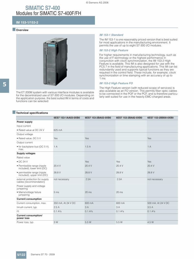
SIMATIC S7-400Modules for SIMATIC S7-400F/FH
IM 153-1/153-2
5/122 Siemens ST 70 · 2009
5
■ Overview
The ET 200M system with various interface modules is available for the decentralized use of S7-300 I/O modules. Depending on the application purpose, the best suited IM in terms of costs and functions can be selected:
IM 153-1 Standard
The IM 153-1 is one reasonably priced version that is best suited for most applications in the manufacturing environment. It permits the use of up to eight S7-300 I/O modules.
IM 153-2 High Feature
For higher requirements in manufacturing technology, such as the use of F-technology or the highest performance in conjunction with clock synchronization, the IM 153-2 High Feature is available. This IM is also designed for use with the PCS 7 in the field of manufacturing applications. This IM can be redundantly used and supports typical functions as they are required in the control field. These include, for example, clock synchronization or time stamping with an accuracy of up to 1 ms.
IM 153-2 High Feature FO
The High Feature version (with reduced scope of services) is also available as an FO version. This permits fiber optic cables to be connected in the POF or the PCF, and is therefore particu-larly well suited for use in the heavily EMC-charged areas.
■ Technical specifications
6ES7 153-1AA03-0XB0 6ES7 153-2BA02-0XB0 6ES7 153-2BA82-0XB0 6ES7 153-2BB00-0XB0
Power supply
Input current
• Rated value at DC 24 V 625 mA
Output voltage
• Rated value, DC 5 V Yes Yes Yes
Output current
• for backplane bus (DC 5 V), max.
1 A 1.5 A 1 A
Supply voltages
Rated value
• DC 24 V Yes Yes Yes
• Permissible range (ripple included), lower limit (DC)
20.4 V 20.4 V 20.4 V 20.4 V
• permissible range (ripple included), upper limit (DC)
28.8 V 28.8 V 28.8 V 28.8 V
external protection for supply cables (recommendation)
not necessary 2.5A 2.5A not necessary
Power supply and voltage jumpering• Mains/voltage failure
jumpering5 ms 20 ms 20 ms
Current consumption
Current consumption, max. 350 mA; At 24 V DC 600 mA 600 mA 500 mA; At 24 V DC
Inrush current, typ. 2.5 A 3 A 3 A 3.5 A
I²t 0.1 A²s 0.1 A²s 0.1 A²s 0.1 A²s
Current consumption/power loss
Power loss, typ. 3 W 5.5 W 5.5 W 4.5 W
© Siemens AG 2008

SIMATIC S7-400Modules for SIMATIC S7-400F/FH
IM 153-1/153-2
5/123Siemens ST 70 · 2009
5
■ Technical specifications (continued)
6ES7 153-1AA03-0XB0 6ES7 153-2BA02-0XB0 6ES7 153-2BA82-0XB0 6ES7 153-2BB00-0XB0
Address area
Adressing volume
• Outputs 128 byte 244 byte 244 byte 128 byte
• Inputs 128 byte 244 byte 244 byte 128 byte
Hardware config.
Number of modules per DP slave interface, max.
8 12 12 8
Communication functions
Bus protocol/transmission protocol
PROFIBUS DP to EN 50170 PROFIBUS DP to EN 50170 PROFIBUS DP PROFIBUS DP to EN 50170
interfaces
PROFIBUS DP, Output current, max.
90 mA 70 mA 70 mA Not applicable
interface physics, RS 485 Yes Yes Yes No
interface physics, LWL No No No Yes
Connection point
PROFIBUS DP 9-pin sub D socket 9-pin SUB-D 9-pin SUB-D optical, 2 x duplex sockets
PROFIBUS DP
Transmission procedure RS 485 RS 485 RS 485 LWL, wavelength 660 nm
Transmission speed, max. 12 MBit/s 12 MBit/s 12 MBit/s 12 MBit/s; 9.6 / 19.2 / 45.45 / 93.75 / 187.5 / 500 Kbit/s; 1.5 / 12 Mbit/s
Node addresses 1 to 125 permitted 1 to 125 permitted 1.125 1 to 125 permitted
automatic detection of transmission speed
Yes Yes Yes 1 to 125 permitted
SYNC capability Yes Yes Yes Yes
FREECE capability Yes Yes Yes Yes
direct data exchange (cross traffic)
Yes; Sender Yes; Sender Yes Yes; Sender
1st interface
DP slave
• GSD file (for DPV1) SIEM801D.GSD; SI01801D.GSG
SI04801.GSG SI0480E.GSG (for DPV1) SIEM8071.GSD; SI018071.GSG (for IM 153-2AB0x); SI028071.GSG (for IM 153-2BB0x)
• automatic baud rate search Yes Yes Yes Yes
CPU/programming
Configuration software
• STEP 7 STEP 7 / COM PROFIBUS / non-Siemens tools via GSD file
Yes; STEP 7 / COM PROFIBUS / non-Siemens tools via GSD file
Yes Yes; STEP 7 / COM PROFIBUS / non-Siemens tools via GSD file
Time stamping
Accuracy 1 ms; 1ms at up to 8 modules; 10ms at up to 12 modules
1 ms; 1ms at up to 8 modules; 10ms at up to 12 modules
10 ms; 10 ms / 3 ms
Number of message buffers 15
Messages per message buffer 20
Number of stampable digital inputs, max.
128; Max. 128 signals / station; max. 32 signals / slot
128; 128 signals / station; max. 32 signals / slot
128
Time format RFC 1119 RFC 1119 Internet (ISP)
© Siemens AG 2008

SIMATIC S7-400Modules for SIMATIC S7-400F/FH
IM 153-1/153-2
5/124 Siemens ST 70 · 2009
5
■ Technical specifications (continued)
6ES7 153-1AA03-0XB0 6ES7 153-2BA02-0XB0 6ES7 153-2BA82-0XB0 6ES7 153-2BB00-0XB0
Time resolution 0.466 ns 0.466 ns 1 ms
Time interval for transmitting the message buffer if a message is present
1 000 ms
Time stamp on signal change rising / falling edge as signal entering or exiting
Yes rising / falling edge as signal entering or exiting
Isolation
Isolation checked with Isolation voltage 500 V Isolation voltage 500 V 500 V DC Isolation voltage 500 V
Environmental requirements
Operating termperature
• min. 0 °C 0 °C -25 °C 0 °C
• max. 60 °C 60 °C 60 °C 60 °C
Air pressure
• Operating height above sea level, max.
3 000 m 3 000 m 3 000 m 3 000 m
Degree of protection
IP 20 Yes Yes Yes Yes
General information
Vendor identification (VendorID) 801Dh 801E 801E 8071h
Dimensions
Dimensions
• Width 40 mm 40 mm 40 mm 40 mm
• Height 125 mm 125 mm 125 mm 125 mm
• Depth 117 mm 117 mm 117 mm 117 mm
Weights
• Weight, approx. 360 g 360 g 360 g 360 g
6ES7 195-7HD10-0XA0 6ES7 195-7HA00-0XA0 6ES7 195-7HB00-0XA0 6ES7 195-7HC00-0XA0
Accessories
belongs to product ET 200M
Dimensions Weights
• Weight, approx. 133 g 111 g 140 g 127 g
© Siemens AG 2008
SIMATIC S7-400Modules for SIMATIC S7-400F/FH
IM 153-1/153-2
5/125Siemens ST 70 · 2009
5
■ Ordering data Order No. Order No.
B3: Subject to export regulations: AL: N and ECCN: 5D992B1
IM 153-1 interface module
Slave interface for connecting an ET 200M to PROFIBUS DP
• Standard temperature range 6ES7 153-1AA03-0XB0
IM 153-2 interface module
Slave interface for connecting an ET 200M to PROFIBUS DP; also for use in redundant systems
• High Feature 6ES7 153-2BA02-0XB0
• High Feature with extended temperature range
6ES7 153-2BA82-0XB0
• Fiber optic 6ES7 153-2BB00-0XB0
Active IM 153 /IM 153 bus module
6ES7 195-7HD10-0XA0
For two IM 153-2 High Feature modules for designing redundant systems
Bus module for ET 200M
• To accommodate a power supply and an IM 153 module for the hot-swapping function during RUN time including bus module cover
6ES7 195-7HA00-0XA0
• To accommodate two 40-mm wide I/O modules for the hot-swapping function
6ES7 195-7HB00-0XA0
• To accommodate one 80-mm wide I/O module for the hot-swapping function
6ES7 195-7HC00-0XA0
ET 200M redundancy bundle 6ES7153-2AR03-0XA0
Comprising two IM 153-2 High Feature modules and one IM 153/IM 153 bus module
Accessories
PROFIBUS bus connector
• 90° outgoing cable, terminating resistor with disconnecting function, without PG connection socket, up to 12 Mbit/s, FastConnect
6ES7 972-0BA51-0XA0
• 90° outgoing cable, terminating resistor with disconnecting function, with PG connection socket, up to 12 Mbit/s, FastConnect
6ES7 972-0BB51-0XA0
SIMATIC DP DIN rail for ET 200M
For insertion of up to 5 bus modules for
• Length: 483 mm (19“) 6ES7 195-1GA00-0XA0
• Length: 530 mm 6ES7 195-1GF30-0XA0
SIMATIC S7-300 DIN rail
• Length: 160 mm 6ES7 390-1AB60-0AA0
• Length: 480 mm (19“) 6ES7 390-1AE80-0AA0
• Length: 530 mm 6ES7 390-1AF30-0AA0
• Length: 830 mm 6ES7 390-1AJ30-0AA0
• Length: 2,000 mm 6ES7 390-1BC00-0AA0
S7 Manual Collection B3 6ES7 998-8XC01-8YE0
Electronic manuals on DVD, multi-language: S7-200, TD 200, S7-300, C7, S7-400, STEP 7, Engineering Tools, Runtime Software, SIMATIC DP (Distributed I/O), SIMATIC HMI (Human Machine Interface), SIMATIC NET (Industrial Commu-nication)
S7 Manual Collection update service for 1 year
B3 6ES7 998-8XC01-8YE2
Scope of delivery: Current DVD "S7 Manual Collection" and the three subse-quent updates
© Siemens AG 2008

SIMATIC S7-400Modules for SIMATIC S7-400F/FH
SIPLUS IM 153-1/153-2
5/126 Siemens ST 70 · 2009
5
■ Overview
• For connecting ET 200M as a slave to PROFIBUS DP (via copper conductors)
• IM 153-2 also for use in redundant PROFIBUS DP systems with S7-400H, software redundancy and S5-155H
• With time stamp functionality and time synchronization• Suitable for isochronous mode
For further technical documentation on SIPLUS, see:http://www.siemens.com/siplus-techdoku
SIPLUS IM 153-1 SIPLUS IM 153-2
Order No. 6AG1 153-1AA03-2XB0 6AG1 153-2BA02-7XB0
Order No. based on 6ES7 153-1AA03-0XB0 6ES7 153-2BA02-0XB0
Ambient temperature range -25 ... +60 °CCondensation permissible
-25 ... +70 °C-25 ... +60 °C (for applications with cUL approval), condensation permissible
Environmental conditions Suited for exceptional medial exposure (e.g. by chlorine sulfur atmosphere)
Approvals CE. UL haz. Loc. CE
Conforms with standard for electronic equipment used on rolling stock (EN 50155, temperature T1, category 1).
Yes No
Technical data The technical data are identical with those of the based-on modules.
SIPLUS bus module for accommodating an 80 mm module
for accommodating two IM 153-2
for accommodating a PS and an IM 153
For accommodating two 40 mm wide I/O modules
Order No. 6AG1 195-7HC00-2XA0 6AG1 195-7HD10-2XA0 6AG1 195-7HA00-2XA0 6AG1 195-7HB00-7XA0
Order No. based on 6ES7 195-7HC00-0XA0 6ES7 195-7HD10-0XA0 6ES7 195-7HA00-0XA0 6ES7 195-7HB00-0XA0
Ambient temperature range -25 ... +60 °CCondensation permissible
Environmental conditions Suited for exceptional medial exposure (e.g. by chlorine sulfur atmosphere)
Approvals CE, cUL (available soon) CE, UL haz. Loc. CE. UL haz. Loc.
Conforms with standard for electronic equipment used on rolling stock (EN 50155, temperature T1, category 1).
No No No No
Technical data The technical data are identical with those of the based-on modules.
© Siemens AG 2008

SIMATIC S7-400Modules for SIMATIC S7-400F/FH
SIPLUS IM 153-1/153-2
5/127Siemens ST 70 · 2009
5
■ Ordering data Order No. Order No.
B7: Subject to export regulations: AL: N and ECCN: EAR99H
IM 153-1 interface module
Slave interface for connecting an ET 200M to PROFIBUS DP
• Standard temperature range 6AG1 153-1AA03-2XB0
IM 153-2 interface module
Slave interface for connecting an ET 200M to PROFIBUS DP; also for use in redundant systems
• High Feature B7 6AG1 153-2BA02-7XB0
Active IM 153/IM 153 bus module
6AG1 195-7HD10-2XA0
For two IM 153-2 High Feature modules for designing redundant systems
Bus module for ET 200M
• To accommodate a power supply and an IM 153 for the hot-swapping function during RUN, incl. bus module cover
6AG1 195-7HA00-2XA0
• To accommodate two 40 mm wide I/O modules for the hot-swapping function
6AG1 195-7HB00-7XA0
• To accommodate one 80 mm wide I/O module for the hot swapping function
6AG1 195-7HC00-2XA0
Accessories see IM 153-1/IM 153-2, page 5/125
© Siemens AG 2008

SIMATIC S7-400Modules for SIMATIC S7-400F/FH
Isolation module
5/128 Siemens ST 70 · 2009
5
■ Overview
• Supports mixed operation of fail-safe signal modules in safety mode and S7-300 standard modules in an ET 200M when Cat. 4 or SIL 3 has to be achieved
• The isolation module is not required if the safety class or safety category to be achieved is less than SIL 3 or Cat. 4, respec-tively
When Cat. 4/SIL 3 is required, the isolation module must be implemented in the following situations:
■ Technical specifications
■ Ordering data Order No.
Application Isolation module must be used
Central use after CPU 31xF-2 DP or CPU 31xF-2 PN/DP
• Only fail-safe modules in the tier Yes, behind the CPU
• Standard and fail-safe modules in the tier
Yes, after the last standard module and before the first fail-safe module
Central use after CPU 31xF-2 DP or CPU 31xF-2 PN/DP in an expansion rack
• Only fail-safe modules in the tier Yes, after the IM 36x
• Standard and fail-safe modules in the tier
Yes, after the last standard module and before the first fail-safe module
Distributed behind the IM 153-2 with copper connection
• Only fail-safe modules in the station
Yes, after the IM 153-2
• Standard and fail-safe modules in the station
Yes, after the last standard module and before the first fail-safe module
Distributed behind the IM 153-2 with fiber-optic connection
• Only fail-safe modules in the station
No
• Standard and fail-safe modules in the station
Yes, after the last standard module and before the first fail-safe module
6ES7 195-7KF00-0XA0
Dimensions Weights
• Weight, approx. 10 g
Isolation module 6ES7 195-7KF00-0XA0
for simultaneous operation of fail-safe and standard modules in an ET 200M
Isolation bus module 6ES7 195-7HG00-0XA0
for accommodating the isolating module in an ET 200M
© Siemens AG 2008

SIMATIC S7-400Modules for SIMATIC S7-400F/FH
SIPLUS isolating module
5/129Siemens ST 70 · 2009
5
■ Overview
• Permits combined operation of fail-safe signal modules in safety mode and standard S7-300 modules in the same ET 200M system.
• Design of PROFIBUS DP lines using copper bus cables. It is not necessary to use fiber-optic cables.
• Every IM 153-x can be used
The isolation module is not required if safety class SIL 2 is to be achieved.
Information about safety class and safety category see isolating module, page 5/128.
■ Ordering data Order No.
■ Overview
• Failsafe input/output modules for use with the SIMATIC S7-400F/FH
• With integrated safety functions• Can only be plugged into the ET 200M• Achievable safety classes in safety operation: SIL 2, SIL 3 to
IEC 61508, AK 4, AK 6 to DIN V 19250, Category 3, 4 to EN 954-1
• Use in standard mode with high diagnostics requirements• Also suitable for redundant operation
For further information see section 4, page 111.
SIPLUS S7-300 isolation module
Order No. 6AG1 195-7KF00-2XA0
Order No. based on 6ES7 195-7KF00-0XA0
Ambient temperature range - 25 ... + 60 °C, condensation permitted
Environmental conditions Suited for exceptional medial exposure (e.g. by chlorine sulfur atmosphere).
Conforms with standard for electronic equipment used on rolling stock (EN 50155, temperature T1, category 1).
Yes
Technical data The technical data are identical with those of the based-on modules.
Isolating module(medial exposure)
6AG1 195-7KF00-2XA0
for simultaneous operation of fail-safe and standard modules in an ET 200M
Accessories see Isolation module, page 5/128
Failsafe input/output modules
© Siemens AG 2008
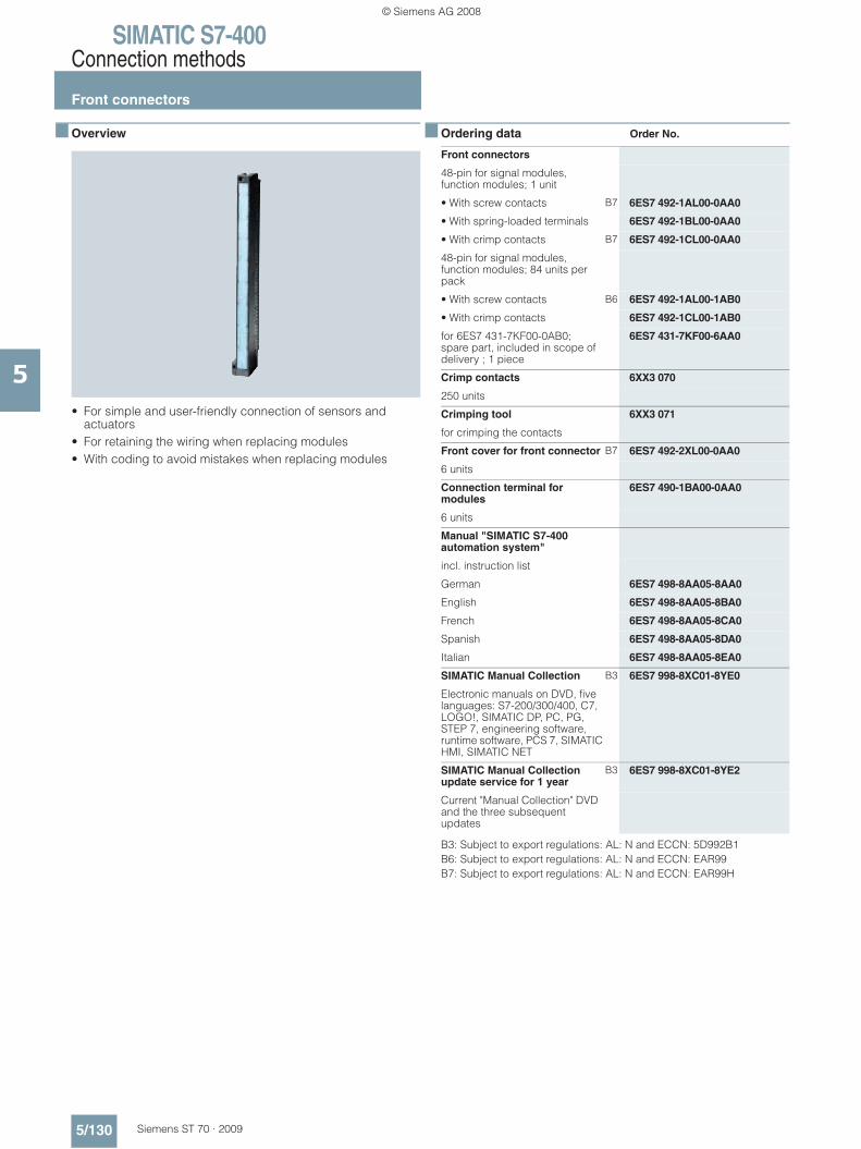
SIMATIC S7-400Connection methods
Front connectors
5/130 Siemens ST 70 · 2009
5
■ Overview
• For simple and user-friendly connection of sensors and actuators
• For retaining the wiring when replacing modules• With coding to avoid mistakes when replacing modules
■ Ordering data Order No.
B3: Subject to export regulations: AL: N and ECCN: 5D992B1B6: Subject to export regulations: AL: N and ECCN: EAR99B7: Subject to export regulations: AL: N and ECCN: EAR99H
Front connectors
48-pin for signal modules, function modules; 1 unit
• With screw contacts B7 6ES7 492-1AL00-0AA0
• With spring-loaded terminals 6ES7 492-1BL00-0AA0
• With crimp contacts B7 6ES7 492-1CL00-0AA0
48-pin for signal modules, function modules; 84 units per pack
• With screw contacts B6 6ES7 492-1AL00-1AB0
• With crimp contacts 6ES7 492-1CL00-1AB0
for 6ES7 431-7KF00-0AB0; spare part, included in scope of delivery ; 1 piece
6ES7 431-7KF00-6AA0
Crimp contacts 6XX3 070
250 units
Crimping tool 6XX3 071
for crimping the contacts
Front cover for front connector B7 6ES7 492-2XL00-0AA0
6 units
Connection terminal for modules
6ES7 490-1BA00-0AA0
6 units
Manual "SIMATIC S7-400 automation system"
incl. instruction list
German 6ES7 498-8AA05-8AA0
English 6ES7 498-8AA05-8BA0
French 6ES7 498-8AA05-8CA0
Spanish 6ES7 498-8AA05-8DA0
Italian 6ES7 498-8AA05-8EA0
SIMATIC Manual Collection B3 6ES7 998-8XC01-8YE0
Electronic manuals on DVD, five languages: S7-200/300/400, C7, LOGO!, SIMATIC DP, PC, PG, STEP 7, engineering software, runtime software, PCS 7, SIMATIC HMI, SIMATIC NET
SIMATIC Manual Collection update service for 1 year
B3 6ES7 998-8XC01-8YE2
Current "Manual Collection" DVD and the three subsequent updates
© Siemens AG 2008
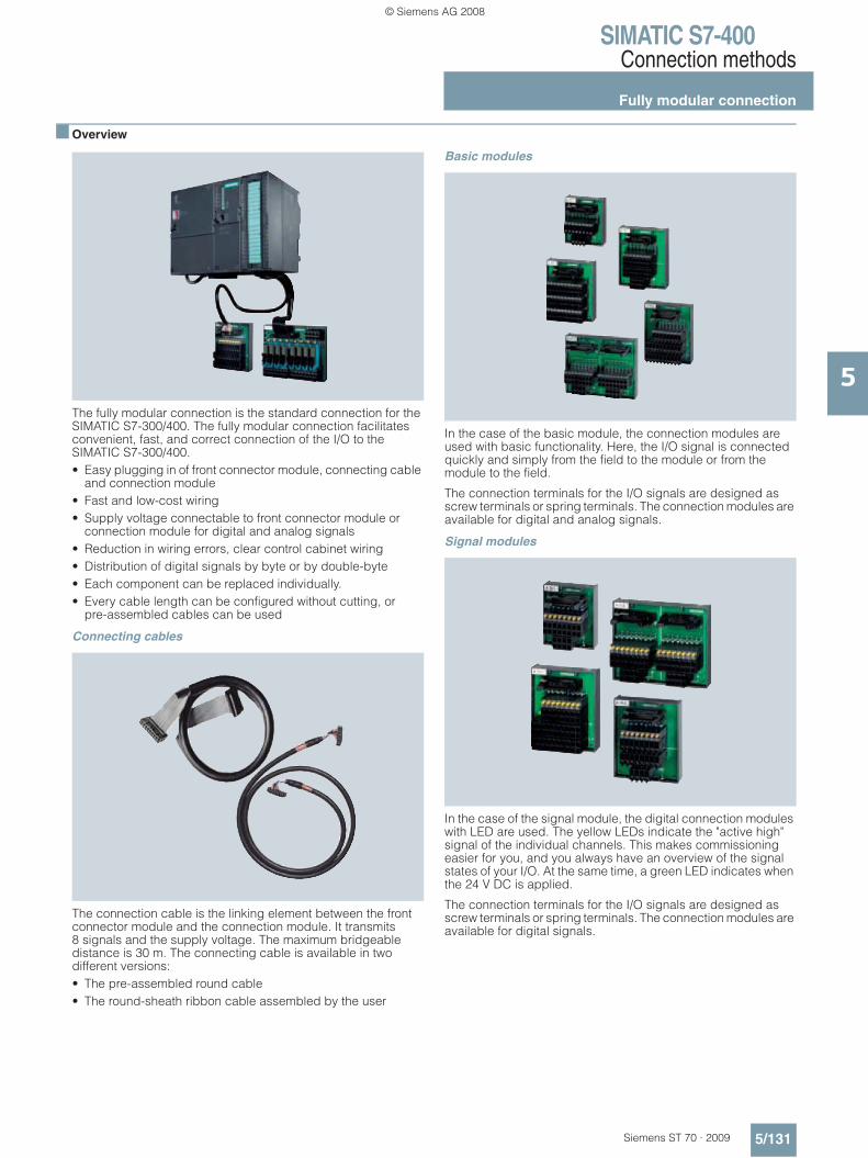
SIMATIC S7-400Connection methods
Fully modular connection
5/131Siemens ST 70 · 2009
5
■ Overview
The fully modular connection is the standard connection for the SIMATIC S7-300/400. The fully modular connection facilitates convenient, fast, and correct connection of the I/O to the SIMATIC S7-300/400.• Easy plugging in of front connector module, connecting cable
and connection module• Fast and low-cost wiring• Supply voltage connectable to front connector module or
connection module for digital and analog signals• Reduction in wiring errors, clear control cabinet wiring• Distribution of digital signals by byte or by double-byte• Each component can be replaced individually.• Every cable length can be configured without cutting, or
pre-assembled cables can be used
Connecting cables
The connection cable is the linking element between the front connector module and the connection module. It transmits 8 signals and the supply voltage. The maximum bridgeable distance is 30 m. The connecting cable is available in two different versions:• The pre-assembled round cable• The round-sheath ribbon cable assembled by the user
Basic modules
In the case of the basic module, the connection modules are used with basic functionality. Here, the I/O signal is connected quickly and simply from the field to the module or from the module to the field.
The connection terminals for the I/O signals are designed as screw terminals or spring terminals. The connection modules are available for digital and analog signals.
Signal modules
In the case of the signal module, the digital connection modules with LED are used. The yellow LEDs indicate the "active high" signal of the individual channels. This makes commissioning easier for you, and you always have an overview of the signal states of your I/O. At the same time, a green LED indicates when the 24 V DC is applied.
The connection terminals for the I/O signals are designed as screw terminals or spring terminals. The connection modules are available for digital signals.
© Siemens AG 2008

SIMATIC S7-400Connection methods
Fully modular connection
5/132 Siemens ST 70 · 2009
5
■ Overview (continued)
Function modules
Function modules are implemented with digital connection modules fitted with relays or optocouplers.
If other voltage or power levels are required in the field, the connection module for output signals TPRo is used. This converts the 24 V DC output signal simply and reliably to another voltage or power level. If 230 V AC input signals have to be trans-mitted to the controller in the field, a connection module with relay TPRi is available that converts the 230 V AC signal simply to 24 V DC. This means you always have the same voltage level on the module side.
■ Technical specifications front connector modules
Wiring rules for the front connector modules
Technical data of front connector module
Rated operating voltage 24 V DC
Max. permissible operating voltage 60 V DC
Max. permissible continuous current• per connector pin
1 A
Max. permissible summation current
4 A/byte (power supply)
Permissible ambient temperature 0 to + 60 °C
Test voltage 0.5 kV, 50 Hz, 60 s
Air gaps and creepage distances IEC 664 (1980), IEC 664 A (1981),in accordance with DIN VDE 0110 (01.89),overvoltage class II, pollution degree 2
Front connector module SIMATIC TOP connect, connection for potential supply
Screw connection
Modules up to 4 connections
Connectable cable cross-sections
• solid cables No
• flexible cables with/without wire end ferrule
0.25 to 1.5 mm2
Number of cables per connection
1 or a combination of 2 conductors up to 1.5 mm2 (total) in a common wire end ferrule
Max. diameter of the cable insulation
3.1 mm
Stripping length of the cables
• without insulating collar 6 mm
• with insulating collar -
Wire-end ferrules to DIN 46228
• without insulating collar Form A; 5 to 7 mm long
• with insulating collar 0.25 to 1.0 mm2
-
• with insulating collar 1.5 mm2
-
Blade width of the screw-driver
3.5 mm (cylindrical shape)
Tightening torque for connecting the cables
0.4 to 0.7 Nm
Front connector module SIMATIC TOP connect, connection for potential supply
Screw connection
Modules up to 6 connections
Connectable cable cross-sections
• solid cables No
• flexible cables with/without wire end ferrule
0.25 bis 0.75 mm2
Number of cables per connection
1 or a combination of 2 conductors up to 1.5 mm2 (total) in a common wire end ferrule
Max. diameter of the cable insulation
2.0 mm
Stripping length of the wires
• without insulating collar 6 mm
• with insulating collar -
Wire-end ferrules to DIN 46228
• without insulating collar Form A; 5 to 7 mm long
• with insulating collar 0.25 to 1.0 mm2
-
• with insulating collar 1.5 mm2
-
Blade width of the screw-driver
3.5 mm (cylindrical shape)
Tightening torque for connecting the cables
0.4 to 0.7 Nm
© Siemens AG 2008
SIMATIC S7-400Connection methods
Fully modular connection
5/133Siemens ST 70 · 2009
5
■ Technical specifications connecting cables
■ Technical specifications basic modules
Wiring rules for connection modules
Technical data of connecting cable from SIMATIC S7 to connection module
Operating voltage 60 V DC
Continuous current per signal conductor
1 A
Max. summation current 4 A/byte
Operating temperature 0 to +60°C
Outer diameter of pre-assembled round cable in mm,unshielded/shielded
Approx. 6.5/7.0
Outer diameter of round-sheath ribbon cable in mm ,16-pole/2 x 16-pole
Approx. 9.5/11.5
Connection module TP1, TP3 and TPK
Max. operating voltage 60 V DC
Continuous current per signal 1 A
Max. summation current (voltage infeed)
4 A/byte
Operating temperature 0 to + 60°C
Mounting position Any
Air gaps and creepage distances IEC Report 664, IEC 664 A, IEC 1131 T2, CSA C22.2 No 142 UL 508, VDE 0160 (12.90), overvoltage category II, pollution degree 3
Dimensions (W x H x D) in mm
• 1-wire connection6ES7 924-0AA10-0A_0
Approx. 55 x 43.2 x 63
• for 3-wire initiators6ES7 924-0CA10-0A_0
Approx. 68 x 43.2 x 80
• for 2 x 8 signals 6ES7 924-1AA10-0A_0
Approx. 100 x 43.2 x 80
Connection module TP2
Max. operating voltage 60 V DC
Continuous current signal conductor
2 A
Operating temperature 0 to + 60°C
Mounting position Any
Air gaps and creepage distances IEC Report 664, IEC 664 A, IEC 1131 T2, CSA C22.2 No 142 UL 508, VDE 0160 (12.90), overvoltage category II, pollution degree 3
Dimensions (W x H x D) in mm
• for 2 ampere modules6ES7 924-0BB10-0A_0
Approx. 68 x 43.2 x 80
Connection module TPA
Max. operating voltage 60 V DC
Continuous current signal conductor
1 A
Operating temperature 0 to + 60°C
Mounting position Any
Air gaps and creepage distances IEC Report 664, IEC 664 A, IEC 1131 T2, CSA C22.2 No 142 UL 508, VDE 0160 (12.90),overvoltage category II, pollution degree 3
Dimensions (W x H x D) in mm
• for 2 analog modules6ES7 924-0CC10-0A_0
Approx. 68 x 43.2 x 80
Connection module TPA, TP1, TP2, TP3, TPK
Spring connection Screw connection
Connectable cable cross-sections
• solid cables No
• flexible cables without wire end ferrule
0.5 to 2.5 mm2
• flexible cables with wire end ferrule in accordance with DIN 46228/1
0.5 to 1.5 mm2 0.5 to 2.5 mm2
(2.5 mm2 with a crimp in accor-dance with EN 60947-1
• flexible cables with wire end ferrule and plastic collar in accordance with DIN 46228/4
0.5 to 1.5 mm2
Number of cables per connection
1 or a combination of 2 cables up to the cross-sections specified above(total) in a shared wire end ferrule
Blade width of the screw-driver
3.5 mm (cylindrical shape)
Tightening torque for connecting the cables
- 0.4 to 0.7 Nm
© Siemens AG 2008

SIMATIC S7-400Connection methods
Fully modular connection
5/134 Siemens ST 70 · 2009
5
■ Technical specifications signal modules
Wiring rules for connection modules
■ Technical specifications function modules
Connection module TP1, TP3 and TPK with LED
Max. operating voltage 24 V DC
Continuous current per signal 1 A
Max. summation current (voltage infeed)
4 A/byte
Operating temperature 0 to + 60 °C
Mounting position Any
Air gaps and creepage distances IEC Report 664, IEC 664 A, IEC 1131 T2, CSA C22.2 No 142 UL 508, VDE 0160 (12.90), overvoltage category II, pollution degree 3
Dimensions (W x H x D) in mm
• 1-wire connection with LED6ES7 924-0AA10-0B_0
Approx. 55 x 43.2 x 63
• for 3-wire initiators with LED6ES7 924-0CA10-0B_0
Approx. 68 x 43.2 x 80
• for 2 x 8 signals with LED6ES7 924-1AA10-0B_0
Approx. 100 x 43.2 x 80
Connection module TP2 with LED
Max. operating voltage 24 V DC
Continuous current per signal conductor
2 A
Operating temperature 0 to + 60 °C
Mounting position Any
Air gaps and creepage distances EC Report 664, IEC 664 A, IEC 1131 T2, CSA C22.2 No 142 UL 508, VDE 0160 (12.90), overvoltage category II, pollution degree 3
Dimensions (W x H x D) in mm
• for 2-ampere modules with LED6ES7 924-0BB10-0B_0
Approx. 68 x 43.2 x 80
Connection module TP1 LED, TPK LED, TP2 LED, TP3 LED
Spring connection Screw connection
Connectable cable cross-sections
• solid cables No
• flexible cables without wire end ferrule
0.5 to 2.5 mm2
• flexible cables with wire end ferrule in accordance with DIN 46228/1
0.5 to 1.5 mm2 0.5 to 2.5 mm2
(2.5 mm2 with a crimp in accor-dance with EN 60947-1)
• flexible cables with wire end ferrule and plastic collar in accordance with DIN 46228/4
0.5 to 1.5 mm2
Number of wires per connection
1 or a combination of 2 conductors up to the cross-sections specified above (total) in a shared wire end ferrule
Blade width of the screw-driver
3.5 mm (cylindrical shape)
Tightening torque for connecting the cables
- 0.4 to 0.7 Nm
Connection module with relay for outputs (TPRo)
Energizing side
Operating voltage for coil 24 V DC
Input circuit Reverse polarity protection and freewheeling diodes
Contact side
Number of relay outputs 8 (NO contacts)
Contact design Single contact, 1 NO contact
Switching capacity (resistive load) max. 4 A/250 V AC, max. 3 A/30 V DC max. 0.6 A/48 V DCmax. 0.4 A/60 V DCrecommended minimum load≥10 mA
Switching frequency 20 cycles/minute
Service life
• mechanical 5 x 10⁶ operating cycles
• electrical 3 x 10⁴ operating cycles at 230 V AC/2 A/ cos ϕ = 1
Operating temperature 0 to +60 °C
Mounting position Any
Air gaps and creepage distances Basic standard IEC 60664-1; UL 508; Cul(Reference CSA C22.2 No. 142)overvoltage category IIIpollution degree 2
Dimensions (W x H x D) in mm
6ES7 924-0BD10-0B_0 Approx. 100 x 45 x 80
Connection module with relay for inputs (TPRi)
Energizing side
Operating voltage for coil 230 VAC
from 207 – 280 V AC
Input circuit Varistors
Contact side
Number of relay outputs 8 (NO contacts)
Contact design Single contact, 1 NO contact
Switching capacity (resistive load) max. 50 mA/24 V AC, max. 50 mA/48 V DC max. 50 mA/60 V DC recommended minimum load ≥5 mA
Switching frequency 200 cycles/minute
Service life
• mechanical 10 x 106 operating cycles
• electrical 3 x 10⁶ operating cycles at 230 V AC/50 mA/ cos ϕ = 1
Operating temperature 0 to +60 °C
Mounting position Any
Air gaps and creepage distances Basic standard IEC 60664-1; UL 508; Cul(Reference CSA C22.2 No. 142)overvoltage category IIIpollution degree 2
Dimensions (W x H x D) in mm
6ES7 924-0BE10-0B_0 Approx. 120 x 45 x 80
© Siemens AG 2008

SIMATIC S7-400Connection methods
Fully modular connection
5/135Siemens ST 70 · 2009
5
■ Technical specifications function modules (continued)
Wiring rules for the connection modules
■ Ordering data front connector modules Order No.
■ Ordering data connect. cables Order No.
B7: Subject to export regulations: AL: N and ECCN: EAR99H
Connection modules TPRo and TPRi
Spring connection Screw connection
Connectable cable cross-sections
• Solid cables No
• flexible cables without wire end ferrule
0.5 to 2.5 mm2
• flexible cables with wire end ferrule in accordance with DIN 46228/1
0.5 to 1.5 mm2 0.5 to 2.5 mm2
(2.5 mm2 with a crimp in accor-dance with EN 60947-1)
• flexible cables with wire end ferrule and plastic collar in accordance with DIN 46228/4
0.5 to 1.5 mm2
Number of wires per connection
1 or a combination of 2 conductors up to the cross-sections specified above (total) in a shared wire end ferrule
Blade width of the screw-driver
3.5 mm (cylindrical shape)
Tightening torque for connecting the cables
- 0.4 to 0.7 Nm
Front connector module (digital 4 x 8 I/O)
Voltage infeed via
• Screw terminals 6ES7 921-4AB00-0AA0
Front connector module (2 x 8 outputs) for 2 ampere digital outputs
Voltage infeed via
• Screw terminals 6ES7 921-4AD00-0AA0
Front connector module (analog)
Voltage infeed via
• Screw terminals 6ES7 921-4AG00-0AA0
Pre-assembled round cable
16-pole, 0.14 mm 2
unshielded
0.5 m 6ES7 923-0BA50-0CB0
1.0 m 6ES7 923-0BB00-0CB0
1.5 m 6ES7 923-0BB50-0CB0
2.0 m 6ES7 923-0BC00-0CB0
2.5 m 6ES7 923-0BC50-0CB0
3.0 m 6ES7 923-0BD00-0CB0
4.0 6ES7 923-0BE00-0CB0
5.0 m 6ES7 923-0BF00-0CB0
shielded
1.0 m 6ES7 923-0BB00-0DB0
2.0 m 6ES7 923-0BC00-0DB0
2.5 m 6ES7 923-0BC50-0DB0
3.0 m 6ES7 923-0BD00-0DB0
4.0 m 6ES7 923-0BE00-0DB0
5.0 m 6ES7 923-0BF00-0DB0
Round-sheath ribbon cable
16-pole, 0.14 mm 2
unshielded
30 m 6ES7 923-0CD00-0AA0
60 m B7 6ES7 923-0CG00-0AA0
shielded
30 m 6ES7 923-0CD00-0BA0
60 m 6ES7 923-0CG00-0BA0
Round-sheath ribbon cable
2 x 16-pole, 0.14 mm 2
unshielded
30 m 6ES7 923-2CD00-0AA0
60 m 6ES7 923-2CG00-0AA0
8 connectors (16-pole)Insulation displacement system with 8 cable grips
6ES7 921-3BE10-0AA0
Accessories
Crimping tool 6ES7 928-0AA00-0AA0
For processing the connectors (female ribbon cable connector)
© Siemens AG 2008
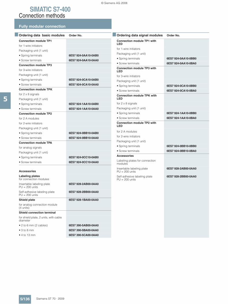
SIMATIC S7-400Connection methods
Fully modular connection
5/136 Siemens ST 70 · 2009
5
■ Ordering data basic modules Order No.
■ Ordering data signal modules Order No.
Connection module TP1
for 1-wire initiators
Packaging unit (1 unit)
• Spring terminals 6ES7 924-0AA10-0AB0
• Screw terminals 6ES7 924-0AA10-0AA0
Connection module TP3
for 3-wire initiators
Packaging unit (1 unit)
• Spring terminals 6ES7 924-0CA10-0AB0
• Screw terminals 6ES7 924-0CA10-0AA0
Connection module TPK
for 2 x 8 signals
Packaging unit (1 unit)
• Spring terminals 6ES7 924-1AA10-0AB0
• Screw terminals 6ES7 924-1AA10-0AA0
Connection module TP2
for 2 A modules
for 2-wire initiators
Packaging unit (1 unit)
• Spring terminals 6ES7 924-0BB10-0AB0
• Screw terminals 6ES7 924-0BB10-0AA0
Connection module TPA
for analog signals
Packaging unit (1 unit)
• Spring terminals 6ES7 924-0CC10-0AB0
• Screw terminals 6ES7 924-0CC10-0AA0
Accessories
Labeling plates for connection modules
Insertable labeling platePU = 200 units
6ES7 928-2AB00-0AA0
Self-adhesive labeling platePU = 200 units
6ES7 928-2BB00-0AA0
Shield plate 6ES7 928-1BA00-0AA0
for analog connection module (4 units)
Shield connection terminal
for shield plate, 2 units, with cable diameter
• 2 to 6 mm (2 cables) 6ES7 390-5AB00-0AA0
• 3 to 8 mm 6ES7 390-5BA00-0AA0
• 4 to 13 mm 6ES7 390-5CA00-0AA0
Connection module TP1 with LED
for 1-wire initiators
Packaging unit (1 unit)
• Spring terminals 6ES7 924-0AA10-0BB0
• Screw terminals 6ES7 924-0AA10-0BA0
Connection module TP3 with LED
for 3-wire initiators
Packaging unit (1 unit)
• Spring terminals 6ES7 924-0CA10-0BB0
• Screw terminals 6ES7 924-0CA10-0BA0
Connection module TPK with LED
for 2 x 8 signals
Packaging unit (1 unit)
• Spring terminals 6ES7 924-1AA10-0BB0
• Screw terminals 6ES7 924-1AA10-0BA0
Connection module TP2 with LED
for 2 A modules
for 2-wire initiators
Packaging unit (1 unit)
• Spring terminals 6ES7 924-0BB10-0BB0
• Screw terminals 6ES7 924-0BB10-0BA0
Accessories
Labeling plates for connection modules
Insertable labeling platePU = 200 units
6ES7 928-2AB00-0AA0
Self-adhesive labeling platePU = 200 units
6ES7 928-2BB00-0AA0
© Siemens AG 2008
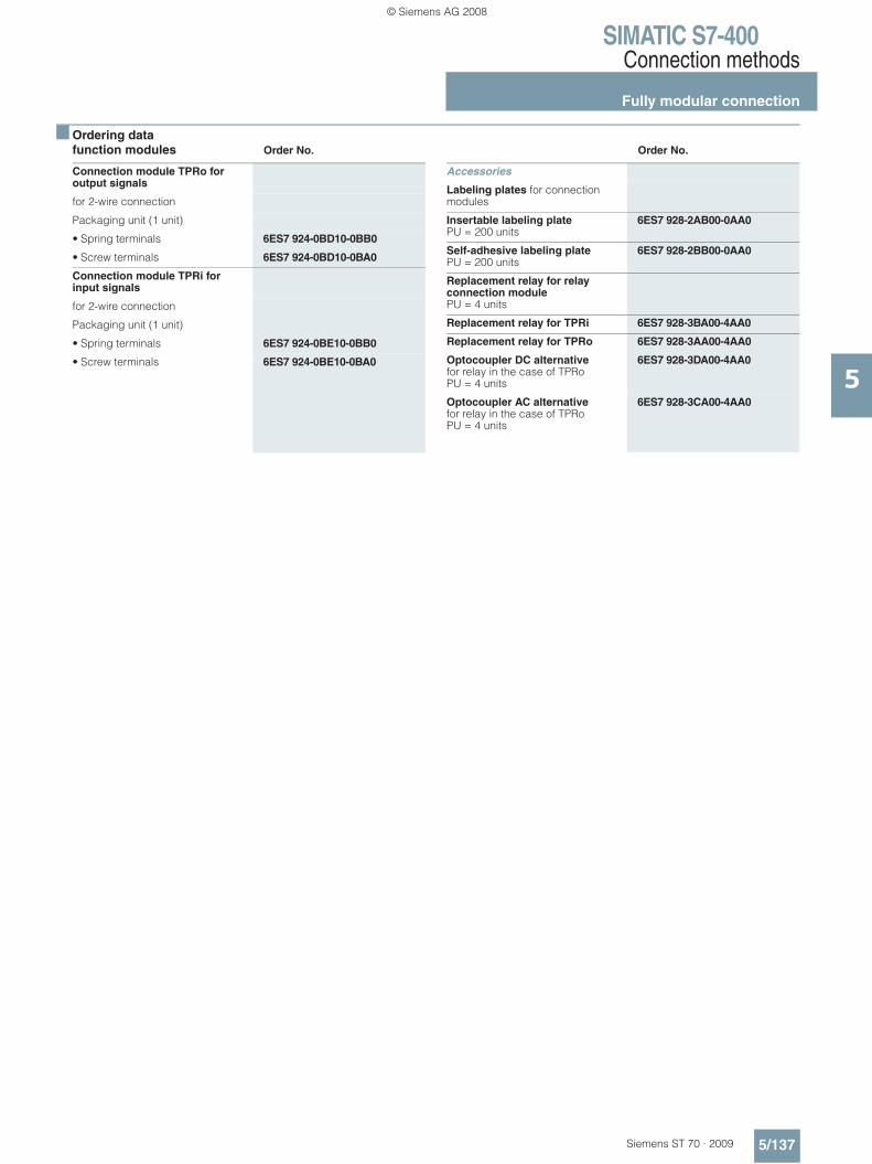
SIMATIC S7-400Connection methods
Fully modular connection
5/137Siemens ST 70 · 2009
5
■ Ordering data function modules Order No. Order No.
Connection module TPRo for output signals
for 2-wire connection
Packaging unit (1 unit)
• Spring terminals 6ES7 924-0BD10-0BB0
• Screw terminals 6ES7 924-0BD10-0BA0
Connection module TPRi for input signals
for 2-wire connection
Packaging unit (1 unit)
• Spring terminals 6ES7 924-0BE10-0BB0
• Screw terminals 6ES7 924-0BE10-0BA0
Accessories
Labeling plates for connection modules
Insertable labeling platePU = 200 units
6ES7 928-2AB00-0AA0
Self-adhesive labeling platePU = 200 units
6ES7 928-2BB00-0AA0
Replacement relay for relay connection module PU = 4 units
Replacement relay for TPRi 6ES7 928-3BA00-4AA0
Replacement relay for TPRo 6ES7 928-3AA00-4AA0
Optocoupler DC alternative for relay in the case of TPRoPU = 4 units
6ES7 928-3DA00-4AA0
Optocoupler AC alternative for relay in the case of TPRoPU = 4 units
6ES7 928-3CA00-4AA0
© Siemens AG 2008

SIMATIC S7-400Connection methods
Flexible connection
5/138 Siemens ST 70 · 2009
5
■ Overview
The flexible connection guarantees a fast and direct connection from the input/output modules of the SIMATIC S7-300/400 to the individual elements in the cabinet.
Already attached single cores reduce the wiring effort.
The core cross-sections of 0,5 mm2 also allow higher currents.
■ Technical specifications
■ Ordering data Order No.
Front connector with single cores
Rated operating voltage 24 V DC
Max. permissible continuous current with simultaneous load on all cores
1.0 A
Permissible ambient temperature 0 to +60 °C
Core type H05V-K or withUL style 1007/1569 CSA TR64
Number of cores 46
Core cross-section 0.5 mm2, Cu
Bundle diameter in mm Approx. 17
Color of core Blue, RAL 5010
Designation of cores Numbered from 3 to 48 (adapter contact = core number)
Fabrication Screw or crimp contacts
Front connector with single coresfor 32-channel digital modulesSIMATIC S7-400, 46 x 0.5 mm2
Core type H05V-K
Screw version
Packaging unit (1 unit)Length:
• 2.5 m 6ES7 922-4BC50-0AD0
• 3.2 m 6ES7 922-4BD20-0AD0
• 5 m 6ES7 922-4BF00-0AD0
• Special lengths on request
Packaging unit (5 units)Length:
• 2.5 m 6ES7 922-4BC50-5AD0
• 3.2 m 6ES7 922-4BD20-5AD0
• 5 m 6ES7 922-4BF00-5AD0
Crimp version
Packaging unit (1 unit)Length:
• 2.5 m 6ES7 922-4BC50-0AE0
• 3.2 m 6ES7 922-4BD20-0AE0
• 5 m 6ES7 922-4BF00-0AE0
• Special lengths on request
Packaging unit (5 units)
• 2.5 m 6ES7 922-4BC50-5AE0
• 3.2 m 6ES7 922-4BD20-5AE0
• 5 m 6ES7 922-4BF00-5AE0
Core type UL/CSA-certified
Screw version
Packaging unit (1 unit)Length:
• 3.2 m 6ES7 922-4BD20-0UD0
• 5 m 6ES7 922-4BF00-0UD0
• Special lengths on request
© Siemens AG 2008

SIMATIC S7-400Racks
Racks
5/139Siemens ST 70 · 2009
5
■ Overview
• The basic mechanical framework of the SIMATIC S7-400/S7-400H
• For accommodating the modules, supplying them with operating voltage and connecting them via the backplane bus
• Several versions for configuring central controllers and expansion racks
UR1 (Universal Rack)• For setting up central controllers and expansion units• For holding up to 18 modules• Also suitable for S7-400H• Also available as aluminum rack
UR2 (Universal Rack)• For setting up central controllers and expansion units• For holding up to 9 modules• Also suitable for S7-400H• Also available as aluminum rack
CR2 (Central Rack)• For setting up central controllers• For holding up to 18 modules• Segmented rack:
For operating two mutually independent S7-400 CPUs without S7-400 Multicomputing, but with communication between the CPUs over the backplane bus (C bus). Both CPUs can address their own local I/O modules (segmented P bus).
CR3 (Central Rack) • For configuring central racks• Optimized for distributed automation solutions due to holding
up to 4 modules
UR2-H • For configuring a complete S7-400H system in one subrack• Also suitable for S7-400:
Operation of 2 separate CPUs with their own I/O (separate P and C buses)
• Can also be used as an expansion unit• For holding up to 18 modules• Also available as aluminum rack
ER1 (Extension Rack)• For setting up expansion units economically• For holding up to 18 modules with restricted functionality• Also suitable for S7-400H• Also available as aluminum rack
ER2 (Extension Rack)• For setting up expansion units economically• For holding up to 9 modules with restricted functionality• Also suitable for S7-400H• Also available as aluminum rack
■ Technical specifications
6ES7 400-1TA01-0AA0
6ES7 400-1TA11-0AA0
6ES7 400-1JA01-0AA0
6ES7 400-1JA11-0AA0
6ES7 401-2TA01-0AA0
6ES7 401-1DA01-0AA0
Hardware config.
Number of single-width slots, max.
18 18 9 9 18; 2 segments with 8 or 10 slots
4
Rack
• K bus Yes Yes Yes Yes Yes Yes
• P bus Yes Yes Yes Yes Yes Yes
Dimensions
Dimensions
• Width 482.5 mm 482.5 mm 257.5 mm 257.5 mm 482.5 mm 130 mm
• Height 290 mm 290 mm 290 mm 290 mm 290 mm 290 mm
• Depth 27.5 mm 27.5 mm 27.5 mm 27.5 mm 27.5 mm 27.5 mm
Weights
• Weight, approx. 4 200 g 3 000 g 2 200 g 1 500 g 4 200 g 750 g
© Siemens AG 2008

SIMATIC S7-400Racks
Racks
5/140 Siemens ST 70 · 2009
5
■ Technical specifications (continued)
■ Ordering data Order No. Order No.
6ES7 400-2JA00-0AA0
6ES7 400-2JA10-0AA0
6ES7 403-1TA01-0AA0
6ES7 403-1TA11-0AA0
6ES7 403-1JA01-0AA0
6ES7 403-1JA11-0AA0
Hardware config.
Number of single-width slots, max.
18 18 18 18 9 9
Rack
• K bus Yes Yes
• P bus Yes Yes Yes Yes Yes Yes
Dimensions
Dimensions
• Width 482.5 mm 482.5 mm 482.5 mm 482.5 mm 257.5 mm 257.5 mm
• Height 290 mm 290 mm 290 mm 290 mm 290 mm 290 mm
• Depth 27.5 mm 27.5 mm 27.5 mm 27.5 mm 27.5 mm 27.5 mm
Weights
• Weight, approx. 4 200 g 3 000 g 4 200 g 2 500 g 2 200 g 1 250 g
UR1 rack 6ES7 400-1TA01-0AA0
for central controllers and expansion units, 18 slots
UR1 aluminum rack 6ES7 400-1TA11-0AA0
for central controllers and expansion units, 18 slots
UR2 rack 6ES7 400-1JA01-0AA0
for central controllers and expansion units, 9 slots
UR2 aluminum rack 6ES7 400-1JA11-0AA0
for central controllers and expansion units, 9 slots
CR2 rack 6ES7 401-2TA01-0AA0
for segmented central controllers, 18 slots, 2 local segments
CR3 rack 6ES7 401-1DA01-0AA0
for central controllers and expansion units, 4 slots; optimized for distributed automation solutions
UR2-H rack 6ES7 400-2JA00-0AA0
for split CCs, 18 slots
UR2-H aluminum rack 6ES7 400-2JA10-0AA0
for split CCs, 18 slots
ER1 rack 6ES7 403-1TA01-0AA0
for expansion units, P bus only, 18 slots
ER1 aluminum rack 6ES7 403-1TA11-0AA0
for expansion units, P bus only, 18 slots
ER2 rack 6ES7 403-1JA01-0AA0
for expansion units, P bus only, 9 slots
ER2 aluminum rack 6ES7 403-1JA11-0AA0
for expansion units, P bus only, 9 slots
Slot cover 6ES7 490-1AA00-0AA0
10 units (spare part)
© Siemens AG 2008
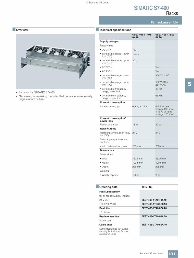
SIMATIC S7-400Racks
Fan subassembly
5/141Siemens ST 70 · 2009
5
■ Overview
• Fans for the SIMATIC S7-400• Necessary when using modules that generate an extremely
large amount of heat
■ Technical specifications
■ Ordering data Order No.
6ES7 408-1TA01-0XA0
6ES7 408-1TB00-0XA0
Supply voltages
Rated value
• DC 24 V Yes
• permissible range, lower limit (DC)
19.2 V
• permissible range, upper limit (DC)
30 V
• AC 120 V Yes
• AC 230 V Yes
• permissible range, lower limit (AC)
85/170 V AC
• permissible range, upper limit (AC)
132 V AC or 264 V AC
• permissible frequency range, lower limit
47 Hz
• permissible frequency range, upper limit
63 Hz
Current consumption
Inrush current, typ. 0.9 A; at 24 V 0.6 A at rated voltage 230 V AC: 1.15 A: at rated voltage 120 V AC
Current consumption/power loss Power loss, max. 11 W 20 W
Relay outputs
Rated input voltage of relay L+ (DC)
24 V 24 V
Switching capacity of the contacts
• with resistive load, max. 200 mA 200 mA
Dimensions
Dimensions
• Width 482.5 mm 482.5 mm
• Height 109.5 mm 109.5 mm
• Depth 235 mm 235 mm
Weights
• Weight, approx. 1.6 kg 2 kg
Fan subassembly
for all racks; Supply voltage
24 V DC 6ES7 408-1TA01-0XA0
120 / 230 V AC 6ES7 408-1TB00-0XA0
Dust filter 6ES7 408-1TA00-7AA0
10 pieces
Replacement fan 6ES7 408-1TA00-6AA0
Spare part
Cable duct 6ES7 408-0TA00-0AA0
Same design as fan subas-sembly, but without fans or electronic units
© Siemens AG 2008

SIMATIC S7-400Racks
Expansion racks
5/142 Siemens ST 70 · 2009
5
■ Overview
• SIMATIC S5 expansion racks for distributed expansion of the SIMATIC S7-400
• For connection to existing SIMATIC S5 systems
The following components can be connected to the SIMATICS7-400:• Expansion racks ER 701-2 and ER 701-3 from the
SIMATIC S5-115U series• Expansion racks EG 183U and EG 185U from the
SIMATIC S5-135U/-155U series
The following requirements must be met for expansion:• IM 463-2 interface module plugged into the SIMATIC S7-400
central controller• IM 314 interface module plugged into SIMATIC S5 expansion
racks• Maximum configuration: • Up to 32 SIMATIC S5 expansion racks can be connected to
one S7-400 central controller• Transmission distance:
The maximum permissible distance between the central controller and the last expansion rack on a line is 600 m
Suitable SIMATIC S5 modules
Expansion rack ER 701-2, ER 701-3 EG 183U, EG 185 U
Digital input modules 6ES5 420-7LA11 6ES5 420-4UA14
6ES5 430-7LA12 6ES5 430-4UA14
6ES5 431-7LA11 6ES5 431-4UA12
6ES5 432-7LA11 6ES5 432-4UA12
6ES5 434-4UA12 6ES5 434-4UA12
6ES5 434-7LA12 6ES5 436-4UA12
6ES5 435-7LA11
6ES5 435-7LB11
6ES5 435-7LC11
6ES5 436-7LA11
6ES5 436-7LB11
6ES5 436-7LC11
Digital output modules 6ES5 441-7LA13 6ES5 441-4UA14
6ES5 451-7LA21 6ES5 451-4UA14
6ES5 453-7LA11 6ES5 453-4UA12
6ES5 454-7LA12 6ES5 454-4UA14
6ES5 454-7LB11 6ES5 455-4UA12
6ES5 455-7LA11 6ES5 456-4UA12
6ES5 456-7LA11 6ES5 457-4UA12
6ES5 456-7LB11 6ES5 458-4UA13
6ES5 457-7LA11 6ES5 458-4UC11
6ES5 458-7LA11
6ES5 458-7LB11
6ES5 458-7LC11
Digital input/output modules
6ES5 482-7LA11 6ES5 482-4UA20
6ES5 482-7LF11
6ES5 482-7LF21
6ES5 482-7LF31
Expansion rack ER 701-2, ER 701-3 EG 183U, EG 185 U
Analog input modules 6ES5 460-7LA13 6ES5 460-4UA13
6ES5 463-4UA12 6ES5 463-4UA13
6ES5 463-4UB12 6ES5 465-4UA13
6ES5 465-7LA13 6ES5 466-4UA11
6ES5 466-4UA11
Analog output modules 6ES5 470-7LA13 6ES5 470-4UA13
6ES5 470-7LB13 6ES5 470-4UB13
6ES5 470-7LC13 6ES5 470-4UC13
Interface modules 6ES5 306-7LA11 6ES5 300-3AB11
6ES5 314-3UA11 6ES5 300-5CA11
© Siemens AG 2008

SIMATIC S7-400Interface modules
IM 460-0
5/143Siemens ST 70 · 2009
5
■ Overview
• Send interface module for central expansion to 5 m• Transmission of P and K bus• Can be plugged into the central controller• Up to 8 expansion racks can be connected (up to 4 per
interface)• Can be used exclusively with IM 461-0
■ Technical specifications
■ Ordering data Order No.
6ES7 460-0AA01-0AB0
Current consumption
from backplane bus DC 5 V, max.
140 mA
Current consumption/power loss Power loss, max. 700 mW
Hardware config.
Cable length between first and last interface module, max.
5 m
Dimensions
Dimensions
• Width 25 mm
• Height 290 mm
• Depth 217 mm
Weights
• Weight, approx. 600 g
IM 460-0 interface module 6ES7 460-0AA01-0AB0
Send interface module for central connection up to 5 m; with C bus transmission
468-1 connecting cable
between IM 460-0 and IM 461-0; IM 460-3 and IM 461-3
0.75 m 6ES7 468-1AH50-0AA0
1.5 m 6ES7 468-1BB50-0AA0
5 m 6ES7 468-1BF00-0AA0
© Siemens AG 2008
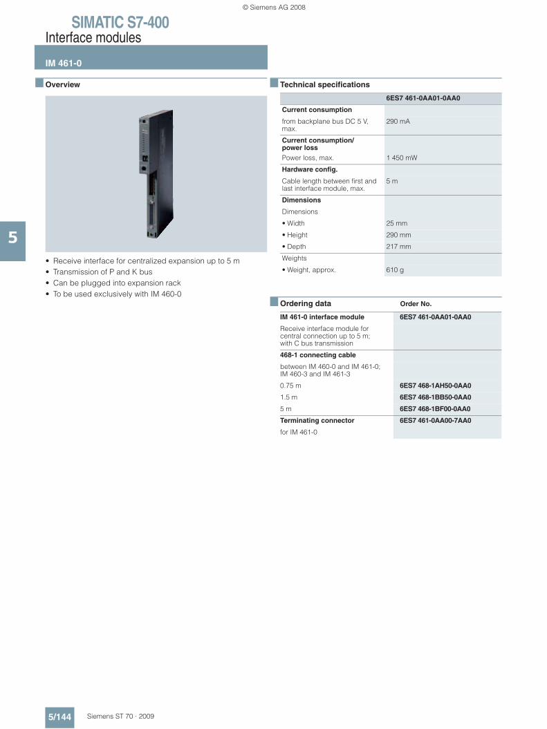
SIMATIC S7-400Interface modules
IM 461-0
5/144 Siemens ST 70 · 2009
5
■ Overview
• Receive interface for centralized expansion up to 5 m• Transmission of P and K bus• Can be plugged into expansion rack• To be used exclusively with IM 460-0
■ Technical specifications
■ Ordering data Order No.
6ES7 461-0AA01-0AA0
Current consumption
from backplane bus DC 5 V, max.
290 mA
Current consumption/power loss Power loss, max. 1 450 mW
Hardware config.
Cable length between first and last interface module, max.
5 m
Dimensions
Dimensions
• Width 25 mm
• Height 290 mm
• Depth 217 mm
Weights
• Weight, approx. 610 g
IM 461-0 interface module 6ES7 461-0AA01-0AA0
Receive interface module for central connection up to 5 m; with C bus transmission
468-1 connecting cable
between IM 460-0 and IM 461-0; IM 460-3 and IM 461-3
0.75 m 6ES7 468-1AH50-0AA0
1.5 m 6ES7 468-1BB50-0AA0
5 m 6ES7 468-1BF00-0AA0
Terminating connector 6ES7 461-0AA00-7AA0
for IM 461-0
© Siemens AG 2008
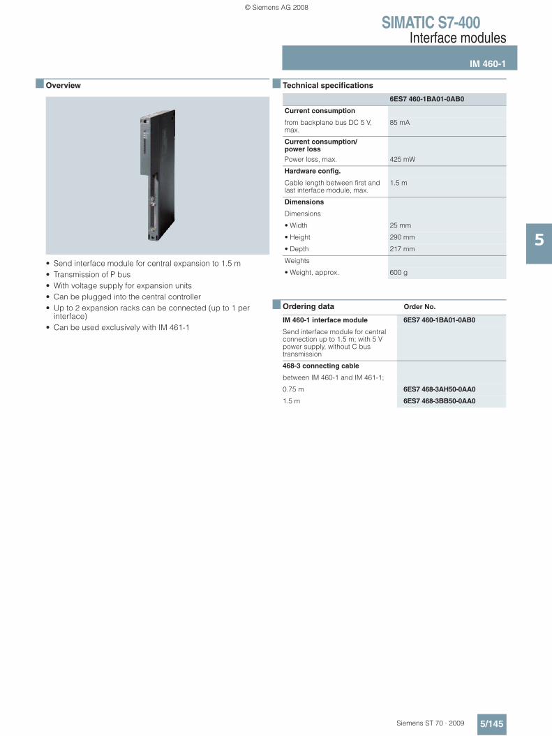
SIMATIC S7-400Interface modules
IM 460-1
5/145Siemens ST 70 · 2009
5
■ Overview
• Send interface module for central expansion to 1.5 m• Transmission of P bus• With voltage supply for expansion units• Can be plugged into the central controller• Up to 2 expansion racks can be connected (up to 1 per
interface)• Can be used exclusively with IM 461-1
■ Technical specifications
■ Ordering data Order No.
6ES7 460-1BA01-0AB0
Current consumption
from backplane bus DC 5 V, max.
85 mA
Current consumption/power loss Power loss, max. 425 mW
Hardware config.
Cable length between first and last interface module, max.
1.5 m
Dimensions
Dimensions
• Width 25 mm
• Height 290 mm
• Depth 217 mm
Weights
• Weight, approx. 600 g
IM 460-1 interface module 6ES7 460-1BA01-0AB0
Send interface module for central connection up to 1.5 m; with 5 V power supply, without C bus transmission
468-3 connecting cable
between IM 460-1 and IM 461-1;
0.75 m 6ES7 468-3AH50-0AA0
1.5 m 6ES7 468-3BB50-0AA0
© Siemens AG 2008
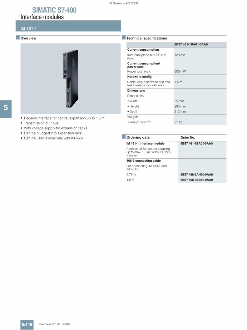
SIMATIC S7-400Interface modules
IM 461-1
5/146 Siemens ST 70 · 2009
5
■ Overview
• Receive interface for central expansion up to 1.5 m• Transmission of P bus• With voltage supply for expansion racks• Can be plugged into expansion rack• Can be used exclusively with IM 460-1
■ Technical specifications
■ Ordering data Order No.
6ES7 461-1BA01-0AA0
Current consumption
from backplane bus DC 5 V, max.
120 mA
Current consumption/power loss Power loss, max. 600 mW
Hardware config.
Cable length between first and last interface module, max.
1.5 m
Dimensions
Dimensions
• Width 25 mm
• Height 290 mm
• Depth 217 mm
Weights
• Weight, approx. 610 g
IM 461-1 interface module 6ES7 461-1BA01-0AA0
Receive IM for central coupling up to max. 1.5 m; without C bus transfer
468-3 connecting cable
For connecting IM 460-1 and IM 461-1
0.75 m 6ES7 468-3AH50-0AA0
1.5 m 6ES7 468-3BB50-0AA0
© Siemens AG 2008
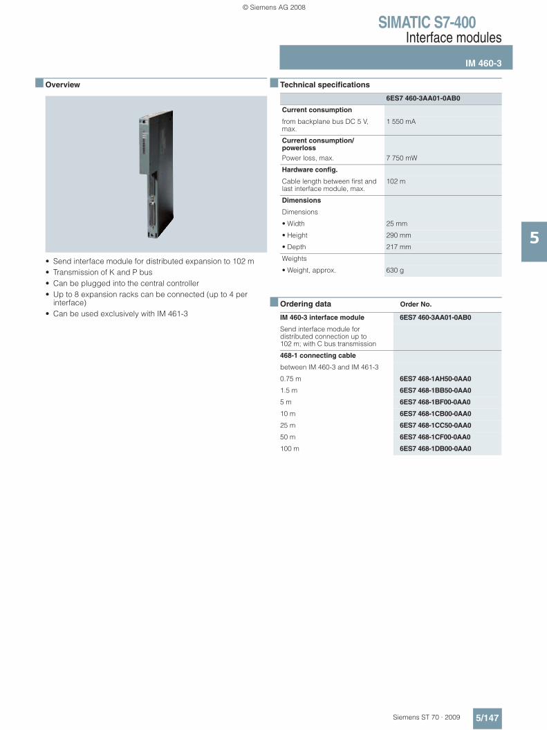
SIMATIC S7-400Interface modules
IM 460-3
5/147Siemens ST 70 · 2009
5
■ Overview
• Send interface module for distributed expansion to 102 m• Transmission of K and P bus• Can be plugged into the central controller• Up to 8 expansion racks can be connected (up to 4 per
interface)• Can be used exclusively with IM 461-3
■ Technical specifications
■ Ordering data Order No.
6ES7 460-3AA01-0AB0
Current consumption
from backplane bus DC 5 V, max.
1 550 mA
Current consumption/powerloss Power loss, max. 7 750 mW
Hardware config.
Cable length between first and last interface module, max.
102 m
Dimensions
Dimensions
• Width 25 mm
• Height 290 mm
• Depth 217 mm
Weights
• Weight, approx. 630 g
IM 460-3 interface module 6ES7 460-3AA01-0AB0
Send interface module for distributed connection up to 102 m; with C bus transmission
468-1 connecting cable
between IM 460-3 and IM 461-3
0.75 m 6ES7 468-1AH50-0AA0
1.5 m 6ES7 468-1BB50-0AA0
5 m 6ES7 468-1BF00-0AA0
10 m 6ES7 468-1CB00-0AA0
25 m 6ES7 468-1CC50-0AA0
50 m 6ES7 468-1CF00-0AA0
100 m 6ES7 468-1DB00-0AA0
© Siemens AG 2008

SIMATIC S7-400Interface modules
IM 461-3
5/148 Siemens ST 70 · 2009
5
■ Overview
• Receive interface for distributed expansion up to 102 m• Transmission of data from the P-bus and C-bus• Can be plugged into expansion rack• To be used exclusively with IM 460-3
■ Technical specifications
■ Ordering data Order No.
6ES7 461-3AA01-0AA0
Current consumption
from backplane bus DC 5 V, max.
620 mA
Current consumption/power loss Power loss, max. 3 100 mW
Hardware config.
Cable length between first and last interface module, max.
102 m
Dimensions
Dimensions
• Width 25 mm
• Height 290 mm
• Depth 217 mm
Weights
• Weight, approx. 620 g
IM 461-3 interface module 6ES7 461-3AA01-0AA0
Receive interface module for distributed connection up to 102 m; with C bus transmission
468-1 connecting cable
between IM 460-3 and IM 461-3
0.75 m 6ES7 468-1AH50-0AA0
1.5 m 6ES7 468-1BB50-0AA0
5 m 6ES7 468-1BF00-0AA0
10 m 6ES7 468-1CB00-0AA0
25 m 6ES7 468-1CC50-0AA0
50 m 6ES7 468-1CF00-0AA0
100 m 6ES7 468-1DB00-0AA0
Terminating connector 6ES7 461-3AA00-7AA0
for IM 461-3
© Siemens AG 2008

SIMATIC S7-400Interface modules
IM 463-2
5/149Siemens ST 70 · 2009
5
■ Overview
• Send interface for distributed expansion with SIMATIC S5 expansion racks up to 600 m
• Can be plugged into the central controller• Up to 8 SIMATIC S5 expansion racks can be connected (up to
4 per interface)• Can be used exclusively with IM 314
■ Technical specifications
■ Ordering data Order No.
6ES7 463-2AA00-0AA0
Current consumption
from backplane bus DC 5 V, max.
1 320 mA
Current consumption/power loss Power loss, max. 6 600 mW
Hardware config.
Cable length between first and last interface module, max.
600 m
Dimensions
Dimensions
• Width 25 mm
• Height 290 mm
• Depth 217 mm
Weights
• Weight, approx. 360 g
IM 463-2 interface module 6ES7 463-2AA00-0AA0
Receiving IM for distributed coupling of SIMATIC S5-EUs up to max. 600 m
© Siemens AG 2008

SIMATIC S7-400Power supplies
PS 405/407 power supply
5/150 Siemens ST 70 · 2009
5
■ Overview
• Power supplies for SIMATIC S7-400• For conversion of AC or DC line voltages to the 5 V DC and
24 V DC operating voltages required• 4 A, 10 A and 20 A output currents• In addition:
- SIPLUS power supply 6AG1 405-0KA02-2AA0 for temper-ature range of -25 to +60 °C and use under medium load (e.g. chlorine/sulfur atmosphere). Technical specifications similar to 6ES7 405-0KA02-0AA0
- SIPLUS power supply 6AG1 407-0KA02-4AA0 for use under medium load (e.g. chlorine/sulfur atmosphere). Technical specifications similar to 6ES7 407-0KA02-0AA0
- SIPLUS power supply 6AG1 407-0KR02-4AA0 for use under medium load (e.g. chlorine/sulfur atmosphere). Technical specifications similar to 6ES7 407-0KR02-0AA0
■ Technical specifications
6ES7 405-0DA02-0AA0 6ES7 405-0KA02-0AA0 6ES7 405-0KR02-0AA0 6ES7 405-0RA02-0AA0
Power supply
Input voltage
• Rated value, DC 24 V Yes Yes Yes Yes
• Rated value, DC 48 V Yes Yes Yes Yes
• Rated value, DC 60 V Yes Yes Yes Yes
• permissible range, lower limit (DC)
19.2 V; dynamic 18.5 V Static 19.2 V, dynamic 18.5 V
19.2 V; dynamic 18.5 V static 19.2 V,dynamic 18.5 V
• permissible range, upper limit (DC)
72 V; dynamic 75.5 V static 72 V, dynamic 75.5 V
72 V; dynamic 75.5 V static: 72 V dynamic 75.5 V
Input current
• Rated value at DC 24 V 2 A 4 A 4 A 7 A
• Rated value at DC 48 V 1 000 mA 2 A 2 A 3.2 A
• Rated value at DC 60 V 800 mA 1.6 A 1.6 A 2.5 A
• Inrush current, max. 18 A; Full width at half maximum 20 ms
18 A; Full width at half maximum 20 ms
18 A; Full width at half maximum 20 ms
56 A; Full width at half maximum 1.5 ms
Output voltage
• Rated value, DC 5 V Yes Yes Yes Yes
• Rated value, DC 24 V Yes Yes Yes Yes
Output current
• for backplane bus (DC 5 V), max.
4 A 10 A; no base load required
10 A; no base load required
20 A; no base load required
• for backplane bus (DC 24 V), max.
0.5 A 1 A; idling-proof 1 A; idling-proof 1 A; idling-proof
• Short-circuit protection Yes Yes Yes Yes
Supply voltages
Power supply and voltage jumpering
• Mains/voltage failure jumpering
20 ms 20 ms 20 ms 20 ms
• Mains/power failure jumper to NAMUR recommendation
Yes Yes Yes Yes
Current consumption/power loss
Power consumption
• Power consumption, typ. 48 W 95 W 95 W 168 W
© Siemens AG 2008

SIMATIC S7-400Power supplies
PS 405/407 power supply
5/151Siemens ST 70 · 2009
5
■ Technical specifications (continued)
6ES7 405-0DA02-0AA0 6ES7 405-0KA02-0AA0 6ES7 405-0KR02-0AA0 6ES7 405-0RA02-0AA0
Current consumption/power loss
Power loss, typ. 16 W 20 W 20 W 44 W
Backup battery
• Backup battery (optional) Yes; 1 x lithium AA; 3.6 V/2.3 Ah
Yes; 2 x lithium AA; 3.6 V/1.9 Ah
Yes; 2 x lithium AA; 3.6 V/2.3 Ah
Yes; 2 x lithium AA; 3.6 V/2.3 Ah
Connection point
Connecting cables/cross sections
3x 1.5 mm2, solid or stranded wire with end sleeve, external diameter 3 to 9 mm
3x 1.5 mm2, solid or stranded wire with end sleeve, external diameter 3 to 9 mm
3x 1.5 mm2, solid or stranded wire with end sleeve, external diameter 3 to 9 mm
3 x 1.5 mm2, solid or stranded wire with end sleeve, external diameter 3 to 9 mm
Isolation
primary/secondary Yes Yes Yes Yes
EMC
• Observance of line harmonic distortion to IEC 61000-3-2, IEC 61000-3-3
Yes Yes
Degree of protection
Class of protection 1; with protective conductor
1; with protective conductor
1; with protective conductor
1; with protective conductor
Standards, approvals, certificates
FM approval Yes; Ta: 0 to 60 °C T4 Yes; Up to 60 °C: T4 Yes; Ta: 0 to 60 °C T4 Yes; Up to 60°C: T4
Dimensions
Required slots 1 2 2 2
Dimensions
Dimensions
• Width 25 mm 50 mm 50 mm 50 mm
• Height 290 mm 290 mm 290 mm 290 mm
• Depth 217 mm 217 mm 217 mm 217 mm
Weights
• Weight, approx. 760 g 1 200 g 1 200 g 1 300 g
6ES7 407-0DA02-0AA0 6ES7 407-0KA02-0AA0 6ES7 407-0KR02-0AA0 6ES7 407-0RA02-0AA0
Power supply
Input voltage
• Rated value, DC 24 V Yes
• Rated value, DC 110 V Yes; Rated value 120 V DC Yes; Rated value 120 V DC Yes; Rated value 120 V DC Yes; Rated value 120 V DC
• Rated value, DC 230 V Yes Yes Yes Yes
• permissible range, lower limit (DC)
88 V 88 V 88 V 88 V
• permissible range, upper limit (DC)
300 V 300 V 300 V 300 V
• Rated value, AC 120 V Yes Yes Yes Yes
• Rated value, AC 230 V Yes Yes Yes Yes
• permissible range, lower limit (AC)
85 V 85 V 85 V 85 V
• permissible range, upper limit (AC)
264 V 264 V 264 V 264 V
© Siemens AG 2008

SIMATIC S7-400Power supplies
PS 405/407 power supply
5/152 Siemens ST 70 · 2009
5
■ Technical specifications (continued)
6ES7 407-0DA02-0AA0 6ES7 407-0KA02-0AA0 6ES7 407-0KR02-0AA0 6ES7 407-0RA02-0AA0
Power supply
Input voltage
• Mains frequency- Rated value 50 Hz Yes Yes Yes Yes- Rated value 60 Hz Yes Yes Yes Yes- permissible range, lower limit 47 Hz 47 Hz 47 Hz 47 Hz- permissible range, upper
limit63 Hz 63 Hz 63 Hz 63 Hz
Input current
• Rated value at DC 110 V 350 mA; at 120 V DC 1 A; at 120 V DC 1 A; at 120 V DC 1.4 A
• Rated value at DC 230 V 190 mA 0.5 A 0.5 A 0.7 A
• Rated value at AC 120 V 0.42 A 0.9 A 0.9 A 1.4 A
• Rated value at AC 230 V 0.22 A 0.5 A 0.5 A 0.7 A
• Inrush current, max. 8.25 A; Full width at half maximum 5 ms
63 A; Full width at half maximum 1 ms
63 A; Full width at half maximum 1 ms
88 A; Full width at half maximum 1.1 ms
Output voltage
• Rated value, DC 5 V Yes Yes
• Rated value, DC 24 V Yes Yes
Output current
• for backplane bus (DC 5 V), max.
4 A; no base load required 10 A; no base load required
10 A; no base load required
20 A; no base load required
• for backplane bus (DC 24 V), max.
0.5 A 1 A; idling-proof 1 A; idling-proof 1 A; idling-proof
• Short-circuit protection Yes Yes Yes Yes
Supply voltages
Power supply and voltage jumpering
• Mains/voltage failure jumpering
20 ms 20 ms 20 ms 20 ms
• Mains/power failure jumper to NAMUR recommendation
Yes Yes Yes Yes
Current consumption/power loss
Power consumption
• Power consumption, typ. 52 W 95 W 95 W
Power loss, typ. 20 W 20 W 20 W 35 W
Backup battery
• Backup battery (optional) Yes; 1 x lithium AA; 3.6 V/2.3 Ah
Yes; 2 x lithium AA; 3.6 V/2.3 Ah
Yes; 2 x lithium AA; 3.6 V/2.3 Ah
Yes; 2 x lithium AA; 3.6 V/2.3 Ah
Connection point
Connecting cables/cross sections
3x 1.5 mm2, solid or stranded wire with end sleeve, external diameter 3 to 9 mm
3x 1.5 mm2, solid or stranded wire with end sleeve, external diameter 3 to 9 mm
3x 1.5 mm2, solid or stranded wire with end sleeve, external diameter 3 to 9 mm
3x 1.5 mm2, solid or stranded wire with end sleeve, external diameter 3 to 9 mm
Isolation
primary/secondary Yes Yes Yes Yes
EMC
• Observance of line harmonic distortion to IEC 61000-3-2, IEC 61000-3-3
Yes Yes Yes Yes
© Siemens AG 2008
SIMATIC S7-400Power supplies
PS 405/407 power supply
5/153Siemens ST 70 · 2009
5
■ Technical specifications (continued)
■ Ordering data Order No. Order No.
B7: Subject to export regulations: AL: N and ECCN: EAR99H
6ES7 407-0DA02-0AA0 6ES7 407-0KA02-0AA0 6ES7 407-0KR02-0AA0 6ES7 407-0RA02-0AA0
Degree of protection
Class of protection 1; with protective conductor
1; with protective conductor
1; with protective conductor
1; with protective conductor
Standards, approvals, certificates
FM approval Yes; Ta: 0 to 60 °C T4 Yes; Ta: 0 to 60 °C T4 Yes; Ta: 0 to 60 °C T4 Yes; Ta: 0 to 60 °C T4
Dimensions
Required slots 1 2 2 2
Dimensions
Dimensions
• Width 25 mm 50 mm 50 mm 50 mm
• Height 290 mm 290 mm 290 mm 290 mm
• Depth 217 mm 217 mm 217 mm 217 mm
Weights
• Weight, approx. 760 g 1 200 g 1 200 g 1 300 g
PS 405 power supply modules
24 V DC; 5 V DC, 24 V DC
4 A 6ES7 405-0DA02-0AA0
10 A, wide range 6ES7 405-0KA02-0AA0
10 A, redundant, wide range 6ES7 405-0KR02-0AA0
20 A, wide range 6ES7 405-0RA02-0AA0
SIPLUS PS 405 power supply modules
(extended temperature range and medium load)
24 V DC; 5 V DC, 24 V DC
10 A, wide range 6AG1 405-0KA02-2AA0
Power plug for PS 405 6ES7 490-0AA00-0AA0
Spare part
Backup battery 6ES7 971-0BA00
Type AA, 1.9 Ah
PS 407 power supply modules
120/230 V AC; 5 V DC, 24 V DC
4 A 6ES7 407-0DA02-0AA0
10 A 6ES7 407-0KA02-0AA0
10 A, redundant 6ES7 407-0KR02-0AA0
20 A 6ES7 407-0RA02-0AA0
SIPLUS PS 407 power supply modules
(extended temperature range and medium load)
120/230 V AC; 5 V DC, 24 V DC
10 A 6AG1 407-0KA02-4AA0
10 A, redundant B7 6AG1 407-0KR02-4AA0
Power plug for PS 407 6ES7 490-0AB00-0AA0
Spare part
Backup battery 6ES7 971-0BA00
Type AA, 1.9 Ah
© Siemens AG 2008
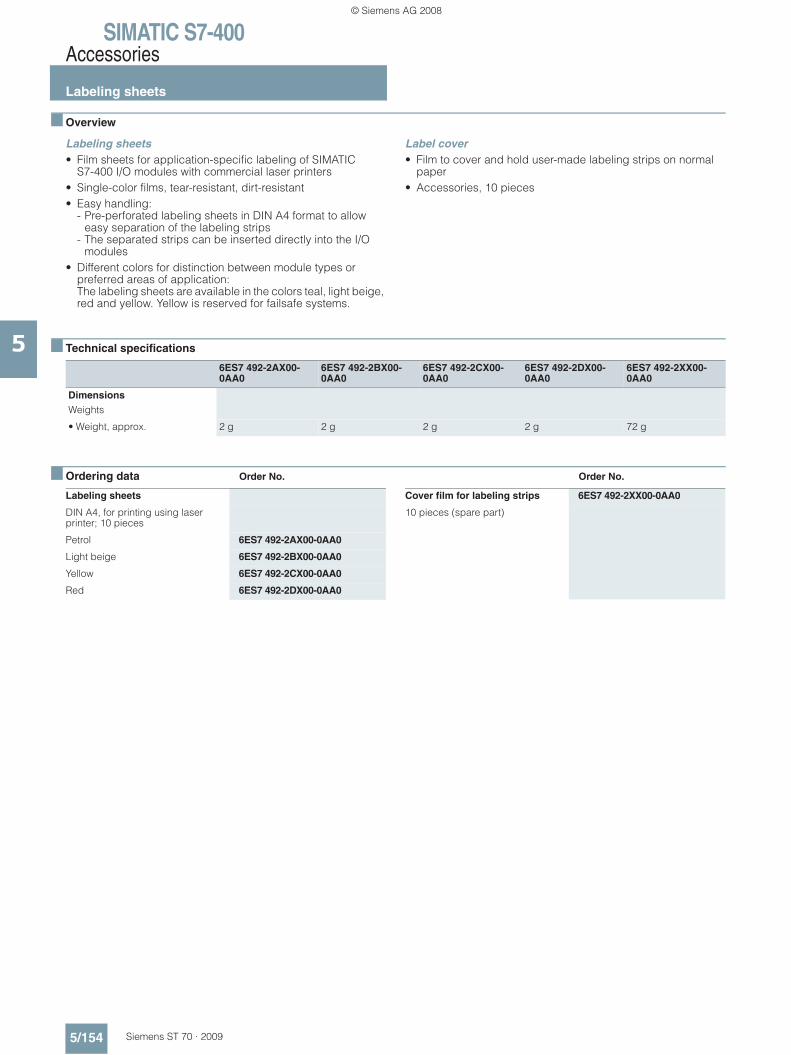
SIMATIC S7-400Accessories
Labeling sheets
5/154 Siemens ST 70 · 2009
5
■ Overview
Labeling sheets• Film sheets for application-specific labeling of SIMATIC
S7-400 I/O modules with commercial laser printers• Single-color films, tear-resistant, dirt-resistant• Easy handling:
- Pre-perforated labeling sheets in DIN A4 format to allow easy separation of the labeling strips
- The separated strips can be inserted directly into the I/O modules
• Different colors for distinction between module types or preferred areas of application: The labeling sheets are available in the colors teal, light beige, red and yellow. Yellow is reserved for failsafe systems.
Label cover• Film to cover and hold user-made labeling strips on normal
paper• Accessories, 10 pieces
■ Technical specifications
■ Ordering data Order No. Order No.
6ES7 492-2AX00-0AA0
6ES7 492-2BX00-0AA0
6ES7 492-2CX00-0AA0
6ES7 492-2DX00-0AA0
6ES7 492-2XX00-0AA0
Dimensions Weights
• Weight, approx. 2 g 2 g 2 g 2 g 72 g
Labeling sheets
DIN A4, for printing using laser printer; 10 pieces
Petrol 6ES7 492-2AX00-0AA0
Light beige 6ES7 492-2BX00-0AA0
Yellow 6ES7 492-2CX00-0AA0
Red 6ES7 492-2DX00-0AA0
Cover film for labeling strips 6ES7 492-2XX00-0AA0
10 pieces (spare part)
© Siemens AG 2008

SIMATIC S7-400Accessories
Spare parts
5/155Siemens ST 70 · 2009
5
■ Overview
Cover film for labeling strips• Teal-colored film for covering and fixing user-created labeling
strips• On standard paper• Spare part
Measuring range module for analog input modules• Plug-in module for selecting the input ranges for analog
modules• 1 module for 2 inputs• Spare part
Module slot cover• Cover plates for unassigned slots in module mounting racks • Spare part, 10 items
Power plug• Plug for connecting the PS 405 and PS 407 power supply
modules to the line supply• Spare part
Exchangeable fan• Fan unit for installation in the fan subassembly • Spare part
Exchangeable monitoring unit• Electronic monitoring unit for the fan subassembly • Spare part
Exchangeable power supply unit• Power supply unit for installation in the fan subassembly • Spare part
■ Ordering data Order No.
■
Cover foil for labeling strip 6ES7 492-2XX00-0AA0
10 units (spare part)
Range card for analog input modules
6ES7 974-0AA00-0AA0
1 card for 2 inputs; 2 units (spare part)
Slot covers 6ES7 490-1AA00-0AA0
for racks; 10 units (spare part)
Power plug for PS 405 6ES7 490-0AA00-0AA0
Spare part
Power plug for PS 407 6ES7 490-0AB00-0AA0
Spare part
Replacement fan 6ES7 408-1TA00-6AA0
Spare part
© Siemens AG 2008

SIMATIC S7-400
5/156 Siemens ST 70 · 2009
5
© Siemens AG 2008