Productization and validation of PressTending concept into a RobotStudio Addin
41
Transcript of Productization and validation of PressTending concept into a RobotStudio Addin
Productization and validation of PressTending
concept into a RobotStudio Addin
Master's Thesis in Systems, Control and Mechatronichs
NILS BLOMQVIST
JENS KULLBERG
Department of Signals and SystemsDivision of Automation
CHALMERS UNIVERSITY OF TECHNOLOGYGöteborg, Sweden 2013Master's Thesis 2013:10


MASTER'S THESIS 2013:10
Productization and validation of PressTending concept into a
RobotStudio Addin
Master's Thesis in Systems, Control and MechatronichsNILS BLOMQVISTJENS KULLBERG
Department of Signals and SystemsDivision of Automation
CHALMERS UNIVERSITY OF TECHNOLOGY
Göteborg, Sweden 2013

Productization and validation of PressTending concept into a RobotStudio AddinNILS BLOMQVISTJENS KULLBERG
c©NILS BLOMQVIST, JENS KULLBERG, 2013
Master's Thesis 2013:10Number EX051/2013Department of Signals and SystemsDivision of AutomationChalmers University of TechnologySE-412 96 GöteborgSwedenTelephone: + 46 (0)31-772 1000
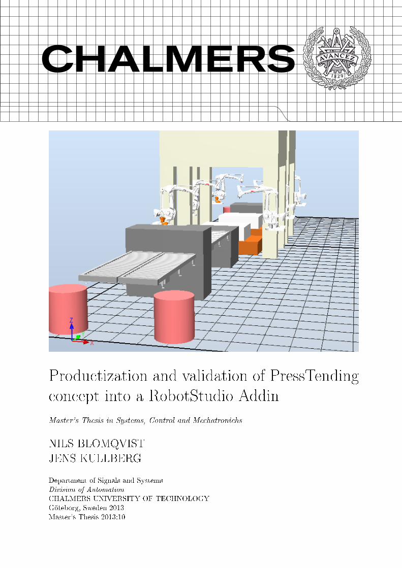
Cover:Auto generated station after user input.
Göteborg, Sweden 2013

Abstract
Simulation and o�-line programming is today two essential concepts in the au-tomation industry. With the advances made in simulation tools and robot systems(and the control of them) more and more scenarios can be simulated. One area wherethis is can be implemented is in Press Lines. In this complex environment much canbe gained by having tools to build up, simulate and optimize the line in a virtualenvironment. This is called Virtual Commissioning (VC) and is the latest advancesmade in digital factoring. The thesis involves the Layout con�guration of a PressLine. It is part of a greater tool for optimizing Press Lines. Using the ObjectiveOriented Programming Language (OOPL) C# (CSharp) a software for organizing,placing and connecting virtual components is created. In a Press Line a constant �owof parts needs to be ful�lled where every component in the line needs to be timed andexactly handled. Every movement being critical and few bu�ers allowed. Changes inthe line directly e�ect other parts of the station. By having a tool that automaticallycan place and rearrange components from simple user inputs facilitates the build upof the station considerably.
In this thesis an add-in has been created to ABBs simulation software RobotStu-dio. The add-in is created in Visual Studio. A User Interface (UI) is created to letthe user easily take control of the �rst stage, the layout con�guration. The devel-opment of the add-in is done using ABBs Software Development Kits (SDKs) andtherefore well compatible for further expansions. Relationship algorithms have beenderived, which loops through the existing components in the virtual station in orderto determine what relationships should be established. A relationship is de�ned bydetermining which device a robot should interact with, e.g. picking up a part froma load table or leaving to a press. After the relationships has been calculated place-ments are done. Locking segments of the line have been made possible in the add-in.By adding this implementation it is easy for the user to make small changes, whilststill having the possibility to auto correct the rest of the line. Managers for relations,placements and locked objects has been created to keep track of the state the station.The resulting software is a fully functioning add-in with UI for easy control of thedi�erent scenarios. The overall project successfully ful�ls the outset objectives.
Keywords: Press Line, RobotStudio, Digital Factory, Virtual Commissioning, C#, Auto-mated Layout, Robot, ABB, Relations, Programming
, Signals and Systems, Master's Thesis 2013:10 I

Sammanfattning
Simulering och o�ine programmering är idag två viktiga koncept inom automai-tonsindustrin. Med de framsteg som har gjorts med simuleringsverktyg och robotsy-stem (och kontrollen av dem) �er och �er scenarier kan simuleras. Ett område därdetta kan utnyttjas är presslinjer. Det är ett komplicerat område som kräver avan-cerade verktyg för att bygga, simulera och optimera virtuellt. Detta kallas virtuelldrifttagning och representerar de senaste framstegen som gjorts inom digital fabriker.Tesen avhandlar den virtuella drifttagningen av en presslinje. Den är en del av ettstörre projekt för att optimera dessa linjer. Med det objektorienterade programme-ringsspråket C# (CSharp) har en mjukvara utvecklats för att organisera, placera ochkoppla virtuella komponenter. Ett konstant �öde genom presslinjen krävs och varjemoment behöver vara tids- och välkontrollerat. Varje rörelse är kritisk och få bu�rarär tillåtna. Ändringar i linjen påverkar direkt andra delar av linjen. Genom att haett verktyg som automatiskt placerar och ordnar komponenter i linjen genom enklaanvändarinställningar förenklar uppbyggnad och minskar ramp-up tiden.
En addin har utvecklats till ABBs simulationsmjukvara RobotStudio. Addin:en ärskapad i Visual Studio. Ett användargrännssnitt är framtaget som låter användarenta kontroll över de första stegen för att simulera och optimera en presslinje. Utvecklinghar skett med hjälp av ABBs Software Development Kits (SDKs) och är därför välkompatibelt för vidare utveckling. Relationsalgoritmer är framtagna, vilka går igenombe�ntliga komponenter i den virtuella stationen för att avgöra vilka relationer sombehöver skapas. En relation är de�nierad genom att avgöra vilken enhet som robotenska interagera med, t.ex. plocka en komponent från ett laddningsbord eller lämna tillen press. Efter att realationerna är satta så görs placeringarna. Fixering av segmenti linjen har gjorts möjlig i addin:en. Genom att lägga till denna funktion gör detlätt för användaren att ändra saker, utan att förlora möjligheten att autokorrigeraresten av linjen. Hanterare för relationer, placeringar och låsta object har utvecklatsför att hålla koll på tillståndet i linjen. Resulterande mjukvara är en fullt fungerandeaddin med användargränssnitt för enkel kontrol av olika scenarier. Projektet uppfyllerutsatta mål.
Nyckelord: Press Line, RobotStudio, Digital Fabrik, Virtuell Driftsättning, C#, Automa-tisk Layout, Robot, ABB, Relationer, Programmering
II , Signals and Systems, Master's Thesis 2013:10

Contents
Abstract I
Sammanfattning II
Contents III
Acronyms V
Preface VII
1 Introduction 11.1 Purpose and aim . . . . . . . . . . . . . . . . . . . . . . . . . . . . . . . . 21.2 Speci�cations . . . . . . . . . . . . . . . . . . . . . . . . . . . . . . . . . . 3
1.2.1 Speci�cations of the add-in . . . . . . . . . . . . . . . . . . . . . . . 31.2.2 Added speci�cations to the add-in . . . . . . . . . . . . . . . . . . . 3
1.3 Limitations . . . . . . . . . . . . . . . . . . . . . . . . . . . . . . . . . . . 3
2 Theory 42.1 Virtual Commissioning . . . . . . . . . . . . . . . . . . . . . . . . . . . . . 4
2.1.1 Data requirements for VC . . . . . . . . . . . . . . . . . . . . . . . 42.2 Object Oriented Programming Language . . . . . . . . . . . . . . . . . . . 52.3 Three Layer code architecture . . . . . . . . . . . . . . . . . . . . . . . . . 6
2.3.1 Presentation Layer . . . . . . . . . . . . . . . . . . . . . . . . . . . 62.3.2 Business Logic Layer . . . . . . . . . . . . . . . . . . . . . . . . . . 72.3.3 Data Access Layer . . . . . . . . . . . . . . . . . . . . . . . . . . . 7
2.4 RobotStudio Add-ins . . . . . . . . . . . . . . . . . . . . . . . . . . . . . . 72.5 Developing applications for RobotStudio . . . . . . . . . . . . . . . . . . . 8
2.5.1 Software Development Kits . . . . . . . . . . . . . . . . . . . . . . 82.5.2 Mastership . . . . . . . . . . . . . . . . . . . . . . . . . . . . . . . . 92.5.3 The Virtual IRC5 Controller . . . . . . . . . . . . . . . . . . . . . . 92.5.4 Homogeneous Transformation and Matrix4 . . . . . . . . . . . . . . 92.5.5 XML . . . . . . . . . . . . . . . . . . . . . . . . . . . . . . . . . . . 102.5.6 Persistence . . . . . . . . . . . . . . . . . . . . . . . . . . . . . . . 112.5.7 I/O Connections . . . . . . . . . . . . . . . . . . . . . . . . . . . . 112.5.8 Property bindings . . . . . . . . . . . . . . . . . . . . . . . . . . . . 112.5.9 Smart Component . . . . . . . . . . . . . . . . . . . . . . . . . . . 11
3 Method 133.1 Approach . . . . . . . . . . . . . . . . . . . . . . . . . . . . . . . . . . . . 133.2 De�ning challenges . . . . . . . . . . . . . . . . . . . . . . . . . . . . . . . 133.3 Device concept . . . . . . . . . . . . . . . . . . . . . . . . . . . . . . . . . 14
3.3.1 Robot System . . . . . . . . . . . . . . . . . . . . . . . . . . . . . . 143.3.2 Press System . . . . . . . . . . . . . . . . . . . . . . . . . . . . . . 153.3.3 Table . . . . . . . . . . . . . . . . . . . . . . . . . . . . . . . . . . . 15
3.4 Classes . . . . . . . . . . . . . . . . . . . . . . . . . . . . . . . . . . . . . . 153.5 Placement class . . . . . . . . . . . . . . . . . . . . . . . . . . . . . . . . . 17
3.5.1 Auto-Placement Method . . . . . . . . . . . . . . . . . . . . . . . . 173.6 Auto connections . . . . . . . . . . . . . . . . . . . . . . . . . . . . . . . . 183.7 Lock algorithm . . . . . . . . . . . . . . . . . . . . . . . . . . . . . . . . . 18
3.7.1 First . . . . . . . . . . . . . . . . . . . . . . . . . . . . . . . . . . . 18
, Signals and Systems, Master's Thesis 2013:10 III

3.7.2 Second . . . . . . . . . . . . . . . . . . . . . . . . . . . . . . . . . . 183.7.3 Consequences and constraints . . . . . . . . . . . . . . . . . . . . . 20
4 Results 214.1 User interface . . . . . . . . . . . . . . . . . . . . . . . . . . . . . . . . . . 214.2 Auto-layout . . . . . . . . . . . . . . . . . . . . . . . . . . . . . . . . . . . 224.3 Auto-connections . . . . . . . . . . . . . . . . . . . . . . . . . . . . . . . . 224.4 The whole add-in . . . . . . . . . . . . . . . . . . . . . . . . . . . . . . . . 234.5 Locking down . . . . . . . . . . . . . . . . . . . . . . . . . . . . . . . . . . 23
5 Conclusions 25
6 Recommendations and future work 276.1 Implement Automation Markup Language . . . . . . . . . . . . . . . . . . 276.2 Implement dynamic properties for Smart Components . . . . . . . . . . . . 276.3 Remodel UI into Single Step Wizard . . . . . . . . . . . . . . . . . . . . . 27
IV , Signals and Systems, Master's Thesis 2013:10
List of Acronyms
PP PowerPac
HSPL High Speed Press Line
BTP Bhoruka Tech Park
API Application Programming Interface
SDK Software Development Kit
OOPL Object Oriented Programming Language
BLL Business Logic Layer
DAL Data Access Layer
UI User Interface
WPF Windows Presentation Foundation
XML Extensible Markup Language
GUID Globally Unique Identi�er
VC Virtual Commissioning
SIL Software In Loop
HIL Hardware In Loop
, Signals and Systems, Master's Thesis 2013:10 V

VI , Signals and Systems, Master's Thesis 2013:10

Preface
The work on this thesis took place from the 15th of February until 15th of July 2013 atABB Global Industries & Services Ltd as a part of the ABB India Student Intern Program.The o�ce is located at Bhoruka Tech Park (BTP) in Bangalore, India. The internship hasbeen planned under the guidance of Mr. Sudarshan M-V, from Discrete Automation &LV Products Department. An add-in for ABBs simulation tool RobotStudio has beendeveloped. The add-in with implemented user interface automatically places and connectsthe components and robots needed in a High Speed Press Line (HSPL). Furthermore,additional options such as saving layout segments and making changes after the autogeneration is available.
Aknowledgements
Firstly we would like to thank Magnus Larsson at ABB Bangalore for �nding this projectand making it possible for writing it India. We felt very welcome and generously treatedby everyone. Also a big thanks to our supervisor Sudarshan and his team for guidancethroughout our stay in India. Finally, Petter Falkman for believing in this project andhelping us with the report.
Göteborg June 2013Nils Blomqvist, Jens Kullberg
, Signals and Systems, Master's Thesis 2013:10 VII

VIII , Signals and Systems, Master's Thesis 2013:10
1 Introduction
Today's industries are constantly forced to �nd new and more optimal solutions in theirproduction lines. Since the birth of o�-line programming it is no longer a question of �if�rather then �when� a company should optimize their line. O�-line programming is nowa-days widely used in industries all over the globe. It is believed that since the introductionof industrial robots in the late 1960, over 2,3 million of them have been sold. An esti-mated 1.1-1.4 million were still operational by the end of 2011. This accumulated numbervaries with the estimated average service life of a industrial robot system, 11 respectively15 years. In a market estimated to be worth over 25 billion dollars and showing a steadygrowth since the global �nancial crisis in 2009, it is clear that keeping up to date is moreimportant than ever [1].
In production lines today one of the time consuming aspects, when dealing with controlsystems especially, is the ramp up time of the real assembly line. One way to shorten theramp up time is to �rst simulate the factory and thereby acknowledge faults early in thedesign phase. Great advantages has been made over the last years in digital factory/man-ufacturing techniques. The latest trend in digital manufacturing is Virtual Commissioning(VC) which goes one step further than the �Digital Factory� concept. VC incorporates themechatronic behaviour of the components in the line using the actual PLCs in a virtual en-vironment. The idea is to early implement engineering data from the design phase neededfor the simulation, such as CAD components, material �ow, detailed I/O connections forthe control system and IT infrastructure [2].
A Press Line is a series of presses in a linear pattern. They have long been used inthe industry and their goal is to deliver high quality and high output. Press Lines is usedto form metal sheets by passing them through the line and consequently pressing themuntil they have the correct form [3]. Increasing the output of the press line whilst stillkeeping the quality is a complex procedure with many parameters to be considered. Todaymany press lines uses on-line tuning together with manual settings to reduce the cycletime. This is often done with empirical testing by individual operators [4]. The Press Lineconsidered in this thesis is a press-to-press line. This means that no intermediate stationexists between the presses, the work object is instead transferred directly to the next press[5]. In this case by a robot system, which acts as an extractor/unloader for the previouspress and a feeder/loader to the next press. Simulating this procedure is a highly complextask since the whole system is dependent on exact timings and precision throughout theline[4]. Achieving this by o�-line programming and making simulations available will givehigher e�ciency and increased quality.
ABBs own trademarked simulation tool RobotStudio enables both simulation and o�-line programming for robot systems. This type of programming is essential both whenimplementing new robot systems or when updating existing. In order to keep RobotStudiowell suited for di�erent applications, add-ins to the basic program are available. Theseadd-ins are called PowerPac (PP)s and are constantly developed to attend customer de-mands. Developing Addins for RobotStudio is done in di�erent programming languages,ABB's support covers Visual Basic and CSharp(C#) [6].
Several advantages can be made by switching to simulation testing instead of the moretraditional way of shop-�oor testing. Simulation leads to good decisions, which leads toreduced costs and higher e�ciency [7]. Today Press Lines needs advanced calculations in
, Signals and Systems, Master's Thesis 2013:10 1

order to determine the most e�cient cycle time, o�set between presses, necessary parame-ters etc. A new Addin capable of simulating the entire press line would greatly bene�t theindustry and also save both time and money. This thesis concerns the start of this newPP, i.e developing an add-in handling the placement and connections of the componentsneeded to represent the press line in a virtual environment. By reducing the time neededto place all the presses, robot systems and other needed components more time can bespent optimizing the line. In Figure 1.1 the primary components in the line is shown, thevirtual objects represent a loading table, a robot system and a press.
Figure 1.1: A Robot System, Load Table and Press in RobotStudio
1.1 Purpose and aim
This master thesis concerns the development and validation of a subsystem to a new Addin.Fig. 1.2 illustrates the projects development plan and this thesis contribution.
Figure 1.2: Overlook of the development plan. Note; this thesis contribution is colouredgreen.
The add-ins main purpose is to control the automatic placement of the components in avirtual robot station as well as connecting them automatically. The user should, with helpof the add-in, be able to set up a virtual representation of a Press Line.
The add-in solves an otherwise time consuming process of placing and connecting com-ponents before the actual simulation of the cell is possible. The optimization processuses newly developed formulas that are depending on where components are placed in the
2 , Signals and Systems, Master's Thesis 2013:10

robot cell. Possibilities to continuously make changes such as moving, adding or removingcomponents in the station is a necessary feature for later optimization.
1.2 Speci�cations
This thesis revolves around a layout challenge where the user with help of a User Interface(UI) should be able to set the number of available components, such as robots, presses,tables and import them into RobotStudio. Automatically a layout of a Press Line shouldbe created in a controlled way. The add-in should uphold the speci�cations presented 1.2.1in Tab. 1.1 and Tab. 1.2.
1.2.1 Speci�cations of the add-in
The speci�cation on the add-in was presented in the beginning by ABB, [8] and developedaccordingly to their varying priority, noted on a scale of Low, Medium, High.
Speci�cation PriorityAutomatic layout generation from single Step wizard HighAutomatic interconnections with standard I/O signals HighSolution based on Smart Components and standard ABB libraries HighPossibility to import new components in a controlled way Medium
Table 1.1: Speci�cations of the add-in
1.2.2 Added speci�cations to the add-in
During discussions in connection to the planning of the master thesis it became clear thata feature for locking down components was needed. This would enable rearranging thecomplete line automatically with out changing the locked down components. This featurewas not in the original speci�cations.
Added speci�cation PriorityPossibility to lock a components position and attributes Medium
Table 1.2: Added speci�cations of the add-in
1.3 Limitations
With focus lying on implementing the objectives and making the program stable, designof the UI has been limited. No speci�c test program is used, more than what is availablein Visual Studio and RobotStudio. Collision detection will not be added. Developedalgorithms will not be optimized.
, Signals and Systems, Master's Thesis 2013:10 3

2 Theory
This section describes the theory behind the implemented methods and software. It startsby explaining Virtual Commissioning (VC) with its requirements and advantages. Con-tinuing with theory behind the chosen programming language and code structure. Thesection also covers used applications and interfaces such as RobotStudio, development kitsfor said application and continues with underlying math for component placement/move-ments. Persistence in RobotStudio and the XML structure used is also handled in thissection.
2.1 Virtual Commissioning
VC was in the beginning called "soft commissioning" and introduced the possibility of con-necting real systems with virtual models. The testing and validation could now be donebefore implementing a real system. VC extends this concept with added simulation anal-ysis, engineering requirements and a more complete vision of the life cycle of the technicalsystem [2]. It facilitates the transition between the real and digital factory. The goal is totest and validate the control in the virtual environment and then, without changes, connectthe same control to the real system. This enables the development and con�guration ofcontrol systems in parallel with mechanical and electrical development. The possibility fordi�erent groups to work on the same model enables earlier testing and validation of theplant [9]. As can be seen in [2] a reduction of the ramp up time by 15-25%, using VC ona real system, is achieved.
There are two ways of implementing VC. The �rst way is Software In Loop (SIL), whichmeans that the control and system is completely represented virtually. One big advantageis that no hardware is needed and that the simulation and control can be done on a PC.The second way, Hardware In Loop (HIL) is when equipment of the real system is tested inconjunction with the virtual environment. As explained in [10], dividing up the hardwareand software gives four di�erent scenarios explained below and can be seen in Figure 2.1.
1. Real control system and real system: traditional way of commissioning
2. Real control and virtual system
3. Virtual control and real system
4. Virtual control and virtual system: complete VC
Connecting software with hardware in the second and third example can be solved withOPC. One of the advantages of the forth example and VC is that the simulation can berun in the same tool [10]. Tools that make this possible is e.g. CIROS Planner and ABBsRobotStudio.
2.1.1 Data requirements for VC
To achieve full VC and make use of all its advantages engineering data is needed. Thesedata is often available early in the design phase and VC takes advantage of this fact.Collecting these data and implement them in a structured form lays way for the VC. Inaccordance to [2] the data requirements are as follow.
• Simulation models of components covering kinematics, geometries, controller pro-grams and electronics.
4 , Signals and Systems, Master's Thesis 2013:10

Figure 2.1: Combinations of hardware and software solutions
• Design of the production line regarding placement of resources and equipment.
• Material �ow in the line, sequence of operations and relations of processes in theproduction.
• Control systems, either real or virtual.
• I/O signals in the control system and the connections of the resource components.
• Available functionalities such as e.g safety systems and the signals needed to imple-ment them in the commissioning process.
• Communication protocols and software drivers for connections between the controlsystem and the virtual environment (usually TCP/IP).
With these requirements ful�lled the implementation of VC has come a long way. Using VCfacilitates the decisions for the design engineers regarding type and number of components,which type of communications and connections/interfaces between the resources in the line.It is a valuable tool and provides a foundation for easier, time- and cost e�cient setup forproduction [2].
2.2 Object Oriented Programming Language
The chosen programming language C# is an Object Oriented Programming Language(OOPL) developed by Microsoft from C++ and is a part of Microsoft's .NET initiative. Itis designed to be a simple and modern programming language and to be used for developingsoftware components [11]. With OOPL objects are created and relationships between theseobjects are formed. Each object is self-contained and have its own methods/operationsand data/attributes. Complicated systems and entities in real life can be implemented ina direct way. This is made possible by the availability of data abstraction, inheritanceand encapsulation. This way of coding is tolerant to changes and has high �exibility, re-usability and extensibility [12].Each object stems from a class, which, as mentioned above has methods and attributes.The inheritance possibilities gives the option to easily create subclasses. An illustration ofthe class structure can be seen in Fig. 2.2.
, Signals and Systems, Master's Thesis 2013:10 5

Figure 2.2: Class structure example
2.3 Three Layer code architecture
This section presents the theory behind the multi tier architecture, used to achieve a threelayer framework. This is done to simplify the programming process and facilitate changesand increase the development e�ciency. Each layer should only communicate with its clos-est neighbour. Applications constantly change due to user speci�cations, new standardsor other factors. By applying the three layer architecture changes in the code are onlynecessary at certain places.
The three layers consist of from top to bottom: Presentation layer, also know as UI,explained in 2.3.1, Business Logic Layer (BLL), explained in 2.3.2, and Data AccessLayer (DAL), explained in 2.3.3. The �rst layer is the one visible to the user. Thislayer handles input and displays data. The input/output is then transferred to the BLL,where the necessary calculations and calls are done. The BLL is the core of the systemand handles the operations. If access to data is needed it is the BLL that calls the DAL.It is then the DALs task to retrieve or write the data in the database implementation [13].The di�erent layers and the structure can be seen in Fig. 2.3
2.3.1 Presentation Layer
The presentation layer is also called the front layer. It is what the user sees and interactswith. The components use to make this possible is all included in the presentation layer.It handles all the inputs from the user and displays the necessary information [14].
By using Windows Forms adding components to the presentation layer is convenient. Ithas been apart of the .NET Framework since the beginning. Window forms is a librarythat builds up standard components such as buttons and drop down lists. It is well suitedfor business like applications. If there is no need for rich media content in the UI it isequally suited for applications as the newer more graphic Windows Presentation Founda-tion (WPF) [15].
6 , Signals and Systems, Master's Thesis 2013:10

Figure 2.3: Three Layer Structure: UI, BLL and DAL
2.3.2 Business Logic Layer
BLL occupies the middle section of the three-tier planning framework and coordinatesthe application. It handles and processes commands, calculation operations and logicaldecisions. The BLL is the middle-man between the three layers and is the core of thesystem [16],[13].
2.3.3 Data Access Layer
In computer software the DAL, is a part of the application which provides an easy accessto stored data. In object-oriented programming the layer returns a reference to an objectrather than tables of data, though it can be used both ways. Data access components arecreated speci�cally to make the application easier to con�gure and maintain in terms offunctionality [17].
2.4 RobotStudio Add-ins
ABB's simulation tool RobotStudio implements several di�erent functions. Writing a add-in where the application lets the user control certain functions demands some knowledgeby the programmer. To access di�erent functions in RobotStudio by the application theright Software Development Kit (SDK), explained in 2.5.1, has to be used. With thePC-SDK e.g. the application programmer can ask for mastership, explained in 2.5.2,over the virtual IRC5 Controller, explained in 2.5.3.A graphical object in the simulationenviroment contains it position and orientation represented in a 4 × 4 matrix, explainedin 2.5.4. Extensible Markup Language (XML) provides the ability to exchange and storeinformation in RobotStudio, explained in 2.5.5, and how this is done is explained in 2.5.6.
, Signals and Systems, Master's Thesis 2013:10 7

(a) RobotStudio-SDK for de-veloping applicationss for theRobotStudio environment.
(b) PC-SDK is used for writ-ing programs accessing andediting either the real or thevirtual IRC5 Controller.
(c) When constructing in-terfaces and applicationsfor the FlexPendant theFlexpendant-SDK i used.
Figure 2.4: The three SDKs
2.5 Developing applications for RobotStudio
Developing applications for RobotStudio is done with three di�erent SDK with correspond-ing Application Programming Interface (API). The three SDKs are PC SDK, RobotStudioSDK and the FlexPendant SDK. With these SDKs programmers can develop customizedinterfaces suiting user speci�c needs [18],[19].
2.5.1 Software Development Kits
The SDKs comes with the RobotStudio installation. They make it possible to developapplications on the RobotStudio platform and customize it to the users speci�cations.Such as added scripts, extra user interfaces or entire add-ins. These packages/libraries areessential when developing PPs for RobotStudio. The three SDKs are RobotStudio-SDK,PC-SDK and FlexPendant-SDK and are represented in Figure 2.4.
RobotStudio-SDK is the basic SDK needed for developing software applications forRobotStudio. It contains the API crucial for developing, extending and customizing Robot-Studio to the user speci�cations. RobotStudio SDK is also used when creating customSmart Components with Code behind [19], further explained in 2.5.9.
PC-SDK enables programmers to build applications on the PC and connect them to theABB Robot controller (Virtual, Real). The customized applications, be it for third parties,end users or system integrators, can be implemented as stand alone PC applications. Theycan also operate the IRC5 controller via the network.
FlexPendant-SDK gives the possibility to write custom programs for this device andtherefore extend the functionalities available [18]. FlexPendent is a hand held device at-tached to the robot controller. It can handle several of the functions needed to operate therobot, such as: running, creating and editing speci�c programs, jogging the robot etc.
Another advantage of the PC-SDK is the ability to keep track of multiple IRC5 controllers
8 , Signals and Systems, Master's Thesis 2013:10

in the same application, this is not possible with the FlexPendant. The PC application ishowever a remote client and will not have the same privileges as the FlexPendent whichis a local client. Remote clients also need to request Mastership over the Rapid domain,before they get write access [6].
2.5.2 Mastership
In order to control the robots on the shop �oor mastership is needed. This is implementedso that only one person or program has control the robot at any given point. Severalclients can still be logged on with read only access, which is a default access right, but onlyone with write access. This is for security reasons as well as protection from data beingaccidentally overwritten. The same applies for the virtual IRC5 controller in RobotStudio,when a user via an add-in in RobotStudio wants to write to the controller access must �rstbe given. This is done by taking mastership over the controller [6]
2.5.3 The Virtual IRC5 Controller
The IRC5 is ABB's �fth generation robot controller. RobotStudio provides a perfect digitalcopy of the robot system together with strong programming and simulation features [20].In other words, the same code can be executed both in the RobotStudio simulation and onthe shop �oor without any di�erence in behaviour or physical appearance. To write codeaccessing the virtual controller PC-SDK is used [18].
2.5.4 Homogeneous Transformation and Matrix4
The following is a summary of Homogeneous Transformation as explained in [21]. ABBuses via RobotStudio-SDK a 4 × 4 matrix to describe the orientation of an object in theworkspace, the used notation is Matrix4. Every object in the workspace has a Baseframde�ned by a Matrix4. The workspace is the platform where the actual robot cell is placed.The workspace has one de�ned world coordinate system, it acts as a base reference pointand can be placed anywhere in the workspace, usually at (x, y, z) = (0, 0, 0). Each objectsbaseframe is referenced to this coordinate.
An orientation in a three dimensional euclidean space can be represented as three unitvectors, forming a 3× 3 matrix. To explain a rotation of the orientation a rotation matrixcan be used. Given two orientations O0 and O1 in the same origin and with unit vec-tors x0, y0, z0 and x1, y1, z1 respectively, the orientation of O1 with rotation matrix R iscalculated by:
O1 = RO0 (2.1)
Introducing a third orientation O3 and the notation Rij representing going from orientation
i to j. With i, j = 0, 1, 2 the rotation from O0 to O2 is written as R02 = R0
1R12. Worth
noting is that the rotations are not commutative, R21R
10 6= R1
0R21. The rotation matrix for
an angle α around the x-axis is given by:
Rx(α) =
1 0 00 cosα − sinα0 sinα cosα
(2.2)
In the same way the rotations about the y- and z-axis with an angle of β and γ is given by
, Signals and Systems, Master's Thesis 2013:10 9

Ry(β) =
cos β 0 sin β0 1 0
− sin β 0 cos β
(2.3)
Rz(γ) =
cos γ − sin γ 0sin γ cos γ 00 0 1
(2.4)
As mentioned before representing both the rotation and location from one coordinatesystem to another is made possible by the homogeneous transformation matrix. Given twoorientations in space, O0 and O1 with a distance d0
1 between them. With vector pointsp0 and p1 for the di�erent orientations and the rotation matrix R0
1 describing the relativelocation of O0 to O1. The vector points can now be given by
p0 = d01 +R0
1p1. (2.5)
It can also be shown that the inverse transformation holds, which can be written as
p1 = −R10d
01 −R1
0p0. (2.6)
In a more compact way the homogeneous transformation 4× 4 matrix can be written as
A01 =
[R0
1 d01
0T 1
](2.7)
and expresses the coordinate transformation from one frame to another. The �nal matrixwith a slight di�erence, i.e formulating the matrix is, de�ned as:
A01 =
[R0
1 0
d01
T1
](2.8)
2.5.5 XML
XML was introduced in the 1990s and is a way of exchanging and storing data. XML canbe used to share data between almost any application. Even though it is text based andeasily understood for a human eye, processing the information can be quite complex. Theimplementation of the data can be done in di�erent ways and XML leaves much freedom forthe user. With just simple rules to follow, it is very �exible and lets the user decide ratherfreely on how to build up the data storage. For making it possible for di�erent applicationsor even companies a XML schema can be used for exchanging data in a structured andconsistent way. Implementations vary between manipulations of existing XML data, storedata easily read by other applications and standards that already are based on XML [22].
XML code can be created and edited in any standard text editor. The guidelines forXML was de�ned by World Wide Web Consortium (W3C) and is a way of having struc-tured data in plain text. The data structure is formed by creating and organising elementsand attributes. The structure is only bound by some simple rules, and then its up to theuser to decide which form it will take [22]. In Fig. 2.5 the XML document is used forsaving a state of a component with name, position, type etc.
10 , Signals and Systems, Master's Thesis 2013:10

Figure 2.5: XML document saving a state of a component in a virtual environment
2.5.6 Persistence
When RobotStudio is closed the information of the station state needs to be stored some-where. An add-in with connections and relations has a lot of information and have to storethat information between closing and opening the main program. RobotStudio persists thechanges that have been made in the station by providing �Attributes� where informationcan be stored. Any object in RobotStudio inheriting from Project Object (PO), an abstractbase class, can be used to store information. Attributes are stored as key/value pair, forsafety and stability from con�ict with other add-ins it is recommended to associate thekeys with a Globally Unique Identi�er (GUID) and is only known to the client. The valueitself is the XML �le and an example of one is shown in Fig. 2.6 [23].
Figure 2.6: XML document saving a state of a component in a virtual environment
2.5.7 I/O Connections
Each SmartComponent has the ability to communicate with another SmartComponent viaI/O-signals.
2.5.8 Property bindings
Property bindings allow communication between SmartComponents on a higher level, theyconnect values of one property to the value of another. This allows for mathematicalimplementation in the SmartComponents.
2.5.9 Smart Component
Smart Component is a RobotStudio object with or without a 3D graphical representation,that has a added behaviour which can be implemented by code-behind and/or aggregation
, Signals and Systems, Master's Thesis 2013:10 11

Source Object Speci�es the owner of the source propertySource Property Speci�es the source of the bindingTarget Object Speci�es the owner of the target propertyTarget Property Speci�es the target of the binding
Table 2.1: Property binding description
by other Smart Components. The following list describes the di�erent terminologies usedwhen setting up a robot cell and working with Smart Components. The lists is directlycited from [24].
• Code behind A .NET class associated with a Smart Component that can implementcustom behavior by reacting to certain events, for example simulation time steps andchanges in property values.
• [Dynamic] property An object attached to a Smart Component that has value,type and certain other characteristics. The property value is used by code behind tocontrol the behavior of the Smart Component.
• [Property] binding Connects the value of one property to the value of anotherproperty.
• [Property] attributes Key-value pairs that contain additional information abouta dynamic property, for example value constraints.
• [I/O] signal An object attached to a Smart Component that has a value and adirection (input/output), analogous to I/O signals on a robot controller. The signalvalue is used by code behind to control the behavior of the Smart Component.
• [I/O] connection Connects the value of one signal to the value of a di�erent signal.
• Aggregation The process of connecting several Smart Components using bindingsand/or connections in order to implement a more complex behavior.
• Asset Data object contained in a Smart Component
12 , Signals and Systems, Master's Thesis 2013:10
3 Method
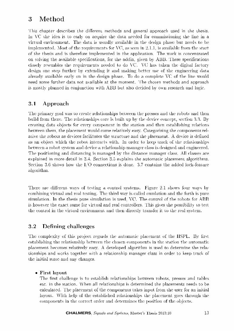
This chapter describes the di�erent methods and general approach used in the thesis.In VC the idea is to early on acquire the data needed for commissioning the line in avirtual environment. The data is usually available in the design phase but needs to beimplemented. Most of the requirements for VC, as seen in 2.1.1, is available from the startof the thesis and is therefore implemented in the application. The work is concentratedon solving the available speci�cations, for the addin, given by ABB. These speci�cationsclosely resembles the requirements needed to do VC. VC has taken the digital factorydesign one step further by extending it and making better use of the engineering dataalready available early on in the design phase. To do a complete VC of the line wouldneed some further data not available at the moment. The chosen methods and approachis mostly planned in conjunction with ABB but also decided by own research and logic.
3.1 Approach
The primary goal was to create relationships between the presses and the robots and thenbuild from there. The relationships core is built up by the device concept, section 3.3. Bycreating data objects for every component in the station and then establishing relationsbetween them, the placement would come relatively easy. Categorising the components rel-ative the robots as devices facilitates the structure and the placement. A device is de�nedas an object which the robot interacts with. In order to keep track of the relationshipsbetween a robot system and device a relationship manager class is designed and engineered.The positioning and distancing is managed by the distance manager class. All classes areexplained in more detail in 3.4. Section 3.5 explains the automatic placement algorithms.Section 3.6 shows how the I/O connections is done. 3.7 contains the added lock-featurealgorithm.
There are di�erent ways of testing a control systems. Figure 2.1 shows four ways bycombining virtual and real testing. The third way is called emulation and the forth is puresimulation. In the thesis pure simulation is used, VC. The control of the robots for ABBis however the exact same for virtual and real controllers. This gives the possibility to testthe control in the virtual environment and then directly transfer it to the real system.
3.2 De�ning challenges
The complexity of this project regards the automatic placement of the HSPL. By �rstestablishing the relationship between the chosen components in the station the automaticplacement becomes relatively easy. A developed algorithm is used to determine the rela-tionships and works together with a relationship manager class in order to keep track ofthe initial state and any changes.
• First layoutThe �rst challenge is to establish relationships between robots, presses and tablesetc. in the station. When all relationships is determined the placements needs to becalculated. The placement of the components takes input from the user for an initiallayout. With help of the established relationships the placement goes through thecomponents in the correct order and determines the position of the objects.
, Signals and Systems, Master's Thesis 2013:10 13
• Change layoutThe possibility to add another press, conveyor or other existing component into thestation is a one of the basic speci�cations. The added components needs to createnew relationships and also get relative positions. With this implemented, options toautomatically recalculate and remodel the station should exist.
• Lock down layoutIt is important not to unintentionally overwrite information regarding a componentsattributes such as position when updating a robot cell. This causes obvious problems.If the user positions robot at a certain position and then updates the robot cell, thesoftware would recalculate and remodel from default settings, which means that thechanges in the station will be overwritten and ignored. A possibility to lock downcomponents at their current position and with its other attributes is a wanted butcomplex feature. This has been solved and is presented in 3.7.
3.3 Device concept
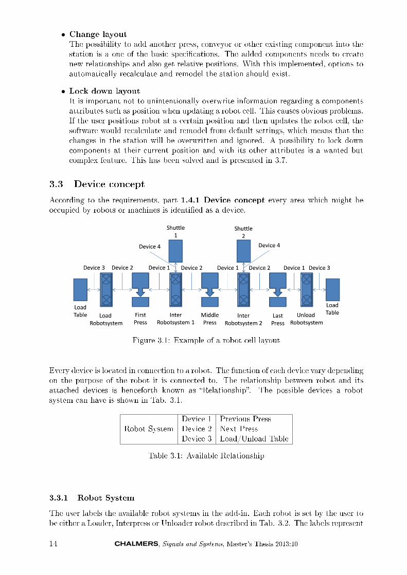
According to the requirements, part 1.4.1 Device concept every area which might beoccupied by robots or machines is identi�ed as a device.
Figure 3.1: Example of a robot cell layout
Every device is located in connection to a robot. The function of each device vary dependingon the purpose of the robot it is connected to. The relationship between robot and itsattached devices is henceforth known as �Relationship�. The possible devices a robotsystem can have is shown in Tab. 3.1.
Robot SystemDevice 1 Previous PressDevice 2 Next PressDevice 3 Load/Unload Table
Table 3.1: Available Relationship
3.3.1 Robot System
The user labels the available robot systems in the add-in. Each robot is set by the user tobe either a Loader, Interpress or Unloader robot described in Tab. 3.2. The labels represent
14 , Signals and Systems, Master's Thesis 2013:10

the robot systems activity in the add-in and not which type of robot. It is implemented insuch a way that there can only exist one or none Loader robot and one or none Unloaderrobot. Each type of robot comes with di�erent settings and conditions e.g. a robot set tobe Loader is given priority over Interpress and Unloader to connect to the press labelledFirst. The concept of labelling presses is explained further in 3.3.2.
Robot SystemLoader Robot SystemInterpress Robot SystemUnloader Robot System
Table 3.2: Available Robot Systems
3.3.2 Press System
Each press can be either device 1, 2 or both at the same time depending on the numberand type of robots in the robot cell. Both meaning the press is previous and next pressat the same time according to Tab. 3.1. Depending on the purpose of the press it exits apossibility to label the press system as either First, Middle or Last press described in Tab.3.3. Each label comes with di�erent settings and conditions e.g. a press labelled First isgiven priority over Middle and Last to connect to a Load table.
Type DeviceFirst Press 1,2 or bothMiddle Press 1,2 or bothLast Press 1,2 or both
Table 3.3: Available Press Systems
3.3.3 Table
A Table can either be Load or Unload table but it is always a device 3 as described in Tab.3.4.
Type DeviceLoad 3Unload 3
Table 3.4: Available Table System
3.4 Classes
This section is divided into two parts, implemented BLL classes and implemented DALclasses, that represents the core of the software and where the actual �work� is done. Thereare more classes working in the background but they give little understanding of the wholeprocess, therefore they are not presented to the fullest in this paper. One such class is the�Helper� class, its only purpose is to �assist� the programmer with commonly used methodsand functions that are not connected to a speci�c object. Fig. 3.2 illustrates a overlook ofthe most important implemented classes in the software.
, Signals and Systems, Master's Thesis 2013:10 15

Figure 3.2: Layer
Implemented DAL Classes Implemented DAL Classes consists of the classes pro-grammed under the DAL, e.g. the class Robot which when called by the user createsa data object representing a real robot system. The data object only contains the infor-mation equal to what a robot �in real life would know�, such as position, orientation andname. Every virtual object in RobotStudio is given a unique identi�cation, GUID, thatis passed onto the object. This is a crucial process that must work due to the fact thatif the GUID does not match the objects unique identi�cation the used algorithm can notseparate a component from di�erent component. The same implementation is used withthe Press and Component class. A robot object does not contain information regarding itsrelationship to other devices neither the distance to them. The information regarding bothrobot and distance relationship for a robot object are created simultaneously and storedin separate collection classes.
Implemented BLL Classes Implemented BLL Classes consists of the classes pro-grammed under the BLL, e.g. the class RobotRelationManager which is created onlyonce when the add-in is started. RobotRelationshipManager stores information regardingall RobotRelationship objects. Each robot class is assigned with a relationship the momentit is created. The distance relationship stores information about the desired distance, set bythe user in the UI, to any device. Each robot class is assigned with a distance relationshipthe moment it is created. DistanceRelationManager manages all DistanceRelation objects.The managing involves calculating the distances set by the user between robot and device.The LockManager class is responsible for and handles the locking down process. It involvesrecalculating distances depending on the new position of the locked object. There are anumber of constraints and limits that make up the rules about where/when/how the useris allowed to move and lock an object explained in 3.7.3.
16 , Signals and Systems, Master's Thesis 2013:10
3.5 Placement class
This chapter explains what and how the Placement class is used and implemented. It alsosits under the BLL but due to the importance to the software it is explained in more detail.How the used automatic placement algorithm is coded and implemented is explained under3.5.1.
3.5.1 Auto-Placement Method
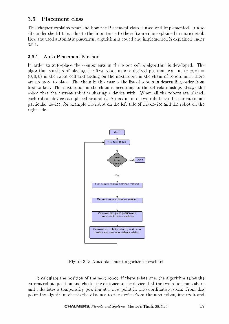
In order to auto-place the components in the robot cell a algorithm is developed. Thealgorithm consists of placing the �rst robot at any desired position, e.g. at (x, y, z) =(0, 0, 0) in the robot cell and adding on the next robot in the chain of robots until thereare no more to place. The chain in this case is the list of robots in descending order from�rst to last. The next robot in the chain is according to the set relationships always therobot that the current robot is sharing a device with. When all the robots are placed,each robots devices are placed around it. A maximum of two robots can be parent to oneparticular device, for example the robot on the left side of the device and the robot on theright side.
Figure 3.3: Auto-placement algorithm �owchart
To calculate the position of the next robot, if there exists one, the algorithm takes thecurrent robots position and checks the distance to the device that the two robot must shareand calculates a temporarily position at a new point in the coordinate system. From thispoint the algorithm checks the distance to the device from the next robot, inverts it and
, Signals and Systems, Master's Thesis 2013:10 17

calculates the position of the next robot. This creates a zigzag �position�-curve shown inFig. 3.4.
Figure 3.4: Zigzag �position�-curve
3.6 Auto connections
One of the objects is to automatically connect the Smart Components in the Station.This is done by creating property bindings and I/O connections. Each Smart Componentneeded for the station is added as an object in the program, and its inputs and outputsis known. Depending on the amount of presses and robots in the station, the bindingsand connections are then created. This is needed for simulations to run. Algorithms builtin to the Press Components and several line-con�guration Smart Components need to beconnected to control the movement and o�set of the presses.
3.7 Lock algorithm
One foreseeable problem is that, for example a robot, has been moved manually insteadof with the UI and followed up by updating the robot cell the software recalculates andremodels from �default� settings. Which means that the manual changes made in thestation will be overwritten and ignored. A possibility to lock components at their currentposition is therefore a needed feature. To solve this a new method is invented and isdescribed in two stages in 3.7.1 and 3.7.2. Depending on which component is locked thereare di�erent consequences and also a set of conditions are implemented both are describedin 3.7.3.
3.7.1 First
When the user selects a component in RobotStudio and presses �Save�, the lock-algorithm�nds the corresponding data object of the component and �ags it as �Saved�. The algorithmlocks the distance relationship in question, making them unchangeable until the robot thatowns the relationship is �agged �Unsaved� by the user. The �owchart in Fig 3.7 illustrateshow the algorithm functions. Note that the backtracking part of the �owchart is explainedin 3.7.2.
3.7.2 Second
The �rst part solves the problem with overriding and ignoring the manual changes but thelocked component will be moved due to the chosen placement method describe in 3.5.1. Thedistances between the locked robot and its devices will still be the same but e.g. if a distancebetween a robot and press is changed and the robot is placed before the locked down robot,the locked robot will be moved. The solution is called backtracking and how it works isillustrated in Fig. 3.6. When the algorithm encounters a robot system in a locked state,
18 , Signals and Systems, Master's Thesis 2013:10

Figure 3.5: Lock algorithm �owchart, including backtracking algorithm
it places the system at the locked position regardless of the newly calculated position ofthe system. Afterwards the backtracking recalculates the positions of the previous systemsusing a algorithm similar to the one showed in Fig. 3.3 but backwards.
Figure 3.6: Backtracking algorithm �owchart
, Signals and Systems, Master's Thesis 2013:10 19
3.7.3 Consequences and constraints
The conditions and constraints are set up to be intuitive and logical.
Conditions Di�erent conditions apply regarding on which component is locked. Whenchosen component is selected and locked the following will happen:
• Robot System All distance relationships owned by the robot are locked.
• Press System The distance relationship owned by the robot which the press wasmoved towards is locked.
• Load/Unload Table The distance relationship owned by the robot which the load/un-load table was moved towards is locked.
• When an unlocked robot is moved outside the base frame of any attached device therobot is moved and no distances will be changed (the whole chain follows).
• When an unlocked press is moved closer to a robot and locked down the rest of thechain behind the press follows.
• When an unlocked press is moved further away from a robot and locked down therest of the chain behind the press follows.
Constraint This constraint is based on logics, e.g. if a robot is located between twolocked down robots, the distances to its devices can not be changed since the locked robotsare set a certain positions. If the robots distances to its devices were to be changed, thelocked robot would be moved which defeats the purpose of the lock-feature.
• It is impossible to move a robots distances, if the robot is located between two otherlocked robots.
20 , Signals and Systems, Master's Thesis 2013:10

4 Results
This section presents the software that has been programmed according to speci�cationsdescribed in Section �Speci�cations� and implemented using �CSharp� in �Visual Studio�for �RobotStudio�. Ideally the results of this paper would be best presented in a physicaldemonstration; however, this is not possible in this format. The results are thereforepresented in scenarios during di�erent circumstances.
4.1 User interface
In this scenario there are three robots in the robot cell, one of each type. Fig. 4.1a showsthe main window of the add-in. The middle window named �Robot Systems� is where theuser can see the added robot systems in the cell. The actual position of the virtual robotin the cell is shown next to its corresponding data objects position. It is implemented inthis prototype as a check point but is not needed in the �nished product. The top parthandles the adding of components from other ABB libraries e.g. conveyor belts as in 4.2,Fig. 4.2a and Fig. 4.2b
(a) Main window of the add-in (b) Distance controller in the add-in
Figure 4.1: Pictures of user interface, need new ones
Fig. 4.1b shows the distance controller, reached by the �Open Edit Window� button inthe main window. Firstly, this is where all robots distance can be changed by selecting arobot from the list and then which device can be selected right next to the list. Secondly,at the bottom of the windows is where the lock function is implemented, consisting of a
, Signals and Systems, Master's Thesis 2013:10 21

�Save� and a �Unsave� button. The object to be locked can either be selected from the listor from the virtual environment in RobotStudio by clicking on it. The middle part of thiswindow shows the current distance to the selected robots devices.
4.2 Auto-layout
Because of the �exibility of the add-in it is always possible to add another component, ifavailable, to the cell. To avoid redundancy two scenarios of di�erent layouts is presented.
(a) This station consists of three robot systems, two presses, one load table andone unload table. The cell is also equipped with other components importedfrom other ABB libraries.
(b) This station consists of three robot systems, four presses, one load table andone unload table. The cell is also equipped with other components importedfrom other ABB libraries.
4.3 Auto-connections
These two �gures illustrates the same scenario. Fig. 4.2c shows the connected propertybindings in the cell while in Fig. 4.2d both property bindings, red lines, and I/O connec-tions, green lines.
22 , Signals and Systems, Master's Thesis 2013:10
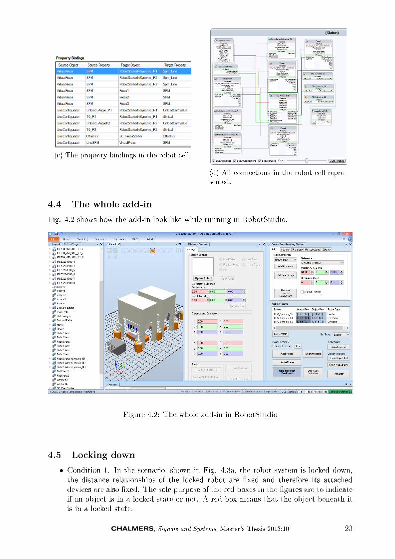
(c) The property bindings in the robot cell.
(d) All connections in the robot cell repre-sented.
4.4 The whole add-in
Fig. 4.2 shows how the add-in look like while running in RobotStudio.
Figure 4.2: The whole add-in in RobotStudio
4.5 Locking down
• Condition 1. In the scenario, shown in Fig. 4.3a, the robot system is locked down,the distance relationships of the locked robot are �xed and therefore its attacheddevices are also �xed. The sole purpose of the red boxes in the �gures are to indicateif an object is in a locked state or not. A red box means that the object beneath itis in a locked state.
, Signals and Systems, Master's Thesis 2013:10 23

• Condition 2. In Fig. 4.3b a robot in the end of the robot chain is locked. In thisscenario distance relationships regarding a robot before the locked robot in the chainare changed. In a straight build order this would mean that the locked robot wouldbe moved according to the new distances. This would severely undermine the lock-function since one of the conditions were that a locked object should not move underany circumstances. Due to the backtracking function the problem is avoided andinstead of moving the locked robot the entire chain of robots before it is moved.
• Condition 3. Fig. 4.3c shows a scenario where a device, a press system, is movedtowards a robot and then locked down. According to the lock-function speci�cationsthe robot system the device is moved towards is put in a locked state. Note; whena robot system is locked as a consequence of moving a device, not all distance rela-tionships owned by the robot are locked down as in Fig. 4.3a only the one belongingto the moved device.
• Condition 4. Fig. 4.3d shows the message box, indicating that the Robot System islocked down and thus it is not allowed to move it.
(a) Condition 1. When the robot systemis locked down its attached devices are alsolocked. The distance relationships to thelocked devices are �xed.
(b) Condition 2. In Fig. 4.3a a robot islocked. In this scenario distances regardingrobots before in the robot chain are changed.
(c) Condition 3. A device, a press system inthis scenario, is moved towards to a robotand then locked down.
(d) Condition 4. Locked and not allowed tobe moved
24 , Signals and Systems, Master's Thesis 2013:10

5 Conclusions
An add-in to ABBs RobotStudio has been developed. The add-in lets the user set-up aPress Line from scratch with existing standard components. Using these components, suchas known Smart Components, I/O connections and Property Bindings are done automati-cally. This facilitates for further implementation and simulation. The user has the abilityto add and remove components from the station in a controlled way. The save function letsthe user edit the station and still have the possibility to auto-rearrange other parts of theline. The add-in has an important role , where it saves time in the set-up of a Press Lineand lays the way for simulation and optimization. The add-in is programmed in a OOPLand in modules where its clear what does what. The structure of the code therefore letsfuture developers add methods and classes easily.
The important results of this paper can be divided into the �ve objective set out in thebeginning.
Automatic layout generation from single Step Wizard A fully functional auto-matic layout has been developed and implemented. The decision was made to change theStep Wizard into a UI instead. This was done due to the fact that graphical design wasnot prioritized. Another reason was that the many settings was better implemented on aUI instead of a Single Step Wizard.
Automatic interconnections with standard I/O The automatic interconnectionswith standard I/O feature has been implemented in the UI and is functioning. Bothdeleting components and their connections manually and with UI has been implemented.The current solution is based on known components and their connections. Should theyhave di�erent in- or outputs, the connection has to be done manually. This is somethingthat could have been �xed if more time was available.
Solution based on Smart Components and standard ABB libraries The solutionhas been implemented based on Smart Components and standard ABB libraries. Moreknowledge of the logics behind the Smart Components and the algorithms for running thesimulation would have been interesting.
Possibility to import new components in a controlled way The solution has beenwith the possibility to add new components to each already existing components in therobot cell. The new components can have any existing component as a reference point andmuch like the automatic layout, it is based on de�ned relationship regarding purpose anddistance. A custom graphical interface for choosing the di�erent standard components andlibraries was something wanted. It is possible to import components through the standardfolder way.
Possibility to lock down components The possibility to lock a component at its cur-rent position and distance relationships has been implemented. This was an added featureby us and solved problems that would otherwise be present.
, Signals and Systems, Master's Thesis 2013:10 25

The outcome of the thesis is a well thought out and working add-in, with that said thereare a couple of things that could have made it even better. A more planned out structureof working would possibly have made the work easier, but was hard to adapt because of thesimultaneous learning curve that was present. Early information and data is as mentionedin the report essential when doing VC. This is something that needs to be considered infuture developments and is more discussed in next section.
26 , Signals and Systems, Master's Thesis 2013:10

6 Recommendations and future work
6.1 Implement Automation Markup Language
Automation Markup Language, AutomationML, is a data format based on XML usedfor storage and exchange of information mostly concerning engineering. Its purpose is tocreate and maintain a standard which greatly simpli�es the process of information storageand exchange in projects. Having this data in a structured way would make it possible toautomate the procedure even further, which is one of the important goals for e�ciency inVC
6.2 Implement dynamic properties for Smart Components
As previously mentioned in Sec.2.5.9 every Smart Component has dynamic properties. Thisproperty value is used by Code Behind to control the behaviour of the Smart Component.It can be used to change the physical lengths of a component, such as width. This wouldgreatly bene�t the simulation and modelling of press lines, when the user can change thesize of for example the die parts in a press to get di�erent sized output. The die is aspecialized tool used in manufacturing to cut or shape materials using a press.
6.3 Remodel UI into Single Step Wizard
As previously mentioned in Sec.5 the end result of the add-in is a UI instead of a single stepwizard due to the fact that the many settings and functions created was better implementedon a UI instead of a Single Step Wizard for this project. Nevertheless a Single Step Wizardwas in the requirements. The amount of work needed to create a wizard is rather limitedsince the necessary functions already exists and have been implemented. There is also anaesthetic matter when designing the wizard which will need work.
, Signals and Systems, Master's Thesis 2013:10 27

References
[1] Executive summary. World Robotics 2012 Industrial Robots.Available through: International Federation of Robotics. [Accessed 28 May 2013]www.ifr.orguploadsmediaWR_Industrial_Robots_2012_Executive_Summary.pdf
[2] S. Makris, G. Michalos, G. Chryssolouris, (2012) Virtual Commissioning of an AssemblyCell with Cooperating Robots. Advances in Decision Sciences.
[3] N.K.Nia, (20122 E�cient Simulation and Optimization for Tandem Press Lines . The-sis for the Degree of Licentiate of Engineering. Department of Signals and Systems.Automation Research Group. Chalmers University of Technology.
[4] B. Svensson, F. Danielsson, B. Lennartson, (2009) Simulation Based Optimization of aSheet-Metal Press Line 978-1-4244-2728-4.IEEE
[5] Tweedy K (1994) Automating the press line. Production vol. 106, no. 2, pp. 36.
[6] ABB AB. Application Manual, (2010) PC SDK Application Manual. Document id3HAC036957-001. ABB Robotics Products. Västerås. Sweden.
[7] A. Pfei�er, B. Kádár, L. Monostori, (2003) Evaluating and improving production con-trol systems by using emulation, Twelfth IASTED International Conference on AppliedSimulation and Modelling, ASM 2003, September 3-5, 2003, Marbella, Spain, pp.:261-267.
[8] D. Vilacoba, ABB Spain. Developing requirements
[9] Z. Liu, N. Suchold, C. Diedrich, (2012) Virtual Commissioning of Automated Systems.ISBN: 978-953-51-0685-2, InTech, DOI: 10.577245730. [Accessed 20 September 2013]http:www.intechopen.combooksautomationvirtual-commissioning-of-automated-systems.
[10] P. Ho�mann et al, (2010) Virtual Commissioning of Manufactoring Systems a Reviewand New Approaches for Simpli�cation. Proceedings 24th European Conference onModelling and Simulation. [Accessed 25 May 2013]http:www.scs-europe.netconf ecms20102010%20accepted%20papersibs_ECMS2010_0041.pdf.
[11] F. Rasheed, (2006) C# School. [e-book]. Fuengirola Spain. Synchron Data.Available through: Programmers Heaven website. [Accessed 4 April 2013]www.programmersheaven.comebookscsharp_ebook.pdf
[12] BB. Wu, (1995) Object Oriented systems analysis and de�nition of manufacturing op-erations, International Journal Of Production Research, vol. 33, no. 4, pp. 956, BusinessSource Premier, EBSCOhost.
[13] X. Hu, J. Xue, H. Liu, (2011) Research of Architecture Pattern Based on .NET Dis-tributed System. 2011 International Conference on Mechatronic Science, Electric Engi-neering and Computer August 19-22, 2011, Jilin, China
[14] Microsoft Developer Network, Microsoft Application Architecture Guide, 2nd Edition- 2009. Design Fundamentals - Chapter 6: Presentation Layer Guidelines. [Accessed 15July 2013] http:msdn.microsoft.comen-uslibraryee658081.aspx.
[15] Microsoft Developer Network, Microsoft Application Architecture Guide, 2nd Edition- 2009. Design Fundamentals Chapter 11: Designing Presentation Components. Accessed15 July 2013]. http:msdn.microsoft.comen-uslibraryee658100.aspx
28 , Signals and Systems, Master's Thesis 2013:10

[16] Microsoft Developer Network, Microsoft Application Architecture Guide, 2nd Edi-tion - 2009. Design Fundamentals - Chapter 7:Business Layer Guidelines. [Accessed 15August 2013]. http:msdn.microsoft.comen-uslibraryee658103.aspx.
[17] Microsoft Developer Network, Microsoft Application Architecture Guide, 2nd Edition- 2009. Design Fundamentals - Chapter 8: Data Layer Guidelines. [Accessed 15 Juli2013]. http:msdn.microsoft.comen-uslibraryee658127.aspx.
[18] ABB AB. Application Manual, (2010) Flexpendant SDK 5.13 Application Manual.Document id 3HAC036958-001. ABB Robotics Products. Västerås. Sweden.
[19] ABB AB. Application Manual, (2011) RobotStudio SDK Reference Manual. ABBRobotics Products. Västerås. Sweden.
[20] ABB AB. Robotics. IRC5 Datasheet IRC5 Industrial Robot Controller. [Accessed 15September 2013]http:www05.abb.comglobalscotscot241.nsf veritydisplayc13e1c5490c61230c125796000515137$�leIRC5%20datasheet%20PR10258%20EN_R13.pdf.
[21] B. Siciliano, L. Sciavicco, L. Villani, G. Oriolo, (2009) Robotics Modelling, Planningand Control. Series: Advanced Textbooks in Control and Signal Processing. XXIV, 632p.
[22] M. MacDonald, D. Mabbutt, A. Freeman, (2010) Pro ASP.NET 4 in VB 2010. XMLChapter. pp 621-680.
[23] ABB AB. RobotStudio Development, Persistence. [Accessed 15 July 2013]http:developercenter.robotstudio.comIndex.aspx?DevCenter=RobotStudio&OpenDocument&Title=Persistent.
[24] ABB AB. Application Manual, (2008-2010) Operating manual RobotStudio 5.13 2008-2010, pp 238. ABB AB Robotics Products SE-721 68 Västerås Sweden
, Signals and Systems, Master's Thesis 2013:10 29