PRODUCTION SPECIFICATION OF AM-OLED MODULE NO. …
16
PRODUCTION SPECIFICATION OF AM-OLED MODULE NO.:TA029FHV10 Customer Name: Customer Part Number: Approved By: Date: Prepared By Checked By Approved By
Transcript of PRODUCTION SPECIFICATION OF AM-OLED MODULE NO. …

PRODUCTION SPECIFICATION
OF AM-OLED
MODULE NO.:TA029FHV10
Customer Name:
Customer Part Number:
Approved By: Date:
Prepared By Checked By Approved By

第 2 页 / 共 17 页
Reversion History
Reversion. No Date Contents Remark
1 2016/7/25 First Version RIOS
1.1 2016/08/15 Adding 5.5 Scan Direction RIOS
1.2 2016/09/15 Adjust brightness luminance to 120 nits RIOS
1.3 2016/12/16 Adjust 5.1.1 Power Characteristic RIOS
AMOLED Production Specification Module No.:TA029FHV10

第 3 页 / 共 17 页
ContentsContents ......................................................................................................................................................... 3
1 Scope ......................................................................................................................................................... 4
2 Features ..................................................................................................................................................... 4
2.1 Product Applications .......................................................................................................................... 4
2.2 Product Features ................................................................................................................................. 4
3 Mechanical Specifications ....................................................................................................................... 4
4 Maximum Rating ..................................................................................................................................... 5
5 Electrical Specifications ........................................................................................................................... 5
5.1 Electrical Characteristics ................................................................................................................... 5
5.1.1 Power Characteristic: ...................................................................................................................... 5
5.1.2 Power supply circuit application (This is for reference only): .................................................... 6
5.2 I/O Connection and Block Diagrams ................................................................................................ 6
5.2.1 I/O Connection .................................................................................................................................... 6
5.2.2 Display Module Block Diagram ....................................................................................................... 7
5.3 Recommended Operating Sequence ................................................................................................. 8
5.4 AC Characteristics(MIPI) ............................................................................................................ 9
5.4.1 HS Data Transmission Burst ............................................................................................................ 9
5.4.2 HS Clock Transmission ..................................................................................................................... 9
5.4.3 Turnaround Procedure ...................................................................................................................... 9
5.4.4 Timing Parameters .......................................................................................................................... 10
5.4.5 Timing requirements for RESETB................................................................................................. 11
5.5 Scan Direction ................................................................................................................................... 11
6 Electro-Optical Specification ................................................................................................................ 12
7 Reliability ................................................................................................................................................ 14
7.1 Environmental Test ............................................................................................................................. 14
7.2 Electrical Test ...................................................................................................................................... 14
8 Outline Dimension Drawing .................................................................................................................. 15
9 Handing Precautions ............................................................................................................................. 16
10 Packing Specification ............................................................................................................................. 16
AMOLED Production Specification Module No.:TA029FHV10

第 4 页 / 共 17 页
1 Scope
This Specification defines AMOLED Product TA029FHV10
2 Features
2.1 Product Applications
VR (Virtual Reality)
2.2 Product Features
1) Display color:16.7M (RGB x 8bits)
2) Display format:2.95” 1080 x 1200
3) Pixel arrangement:Sub Pixel Rendering
4) Interface:MIPI 4 lanes
5) Driver IC:RM 67295
6) Frequency: 90 Hz
3 Mechanical Specifications
Item Specification unit
Dimension outline 52.91 x 62.58 x 0.65 (Including Cushion) mm
LTPS Glass outline 52.91 x 62.58 mm
Encapsulation Glass outline 52.91 x 59.58 mm
Resolution 1080(W) x 1200(H)
Active area 50.11 x 55.68 mm
Diagonal size 2.95 inch
Pixel pitch 23.2 x 46.4 μm
Glass thickness
(LTPS/encapsulation glass) 0.2 / 0.2 mm
Weight 10 (±10%, without FPC) g
Note: Refer to 9 Outline Dimension Drawing
AMOLED Production Specification Module No.:TA029FHV10

第 5 页 / 共 17 页
4 Maximum Rating
Parameter Symbol Spec
Unit Note Min. Typ. Max.
Analog/boost power voltage VCI -0.3 - 5.5 V -
VCI I/O voltage VCI_IF -0.3 - 5.5 V -
I/O voltage VDDI -0.3 - 5.5 V -
VSP voltage VSP -0.3 - 6.6 V -
VPP(OTP power) VPP(NC) - - 8.25 V -
Operating temperature Top -40 85 ℃
Storage temperature Tstg -55 125 ℃
5 Electrical Specifications
5.1 Electrical Characteristics
5.1.1 Power Characteristic:
Item Symbol Min. Typ. Max. Unit Remark
AMOLED Power
positive ELVDD - 4.6 - V
AMOLED power
Negative ELVSS - -2.5 - V Ref
Gamma Voltage VSP 6.1 6.4 6.5 V Ref
Digital Power supply VDDI 1.65 1.8 3.6 V Ref
Analog Power supply VCI 2.5 3.3 4.8 V Ref
Mode Symbol Condition Min. Typ. Max. Unit Remark
@
Gray 255
IELVDD / IELVSS VELVDD = 4.6V
VELVSS =-2.5V
VCI =3.3V
VDDIO =1.8V
VSP =6.4
17 25 mA Ref
IVCI 1.6 1.8 mA Ref
IVDDIO 35 40 mA Ref
IVSP 12 15 mA Ref
AMOLED Production Specification Module No.:TA029FHV10

第 6 页 / 共 17 页
5.1.2 Power supply circuit application (This is for reference only):
Power IC recommend: ST:STAM1330, Silicon Mitus:SM3301, Richtek:RT4722
5.2 I/O Connection and Block Diagrams
5.2.1 I/O Connection
# Pin Name I/O Description
1 ELVSS Power AMOLED power Negative
2 ELVSS Power AMOLED power Negative
3 ELVSS Power AMOLED power Negative
4 ELVDD Power AMOLED power Positive
5 ELVDD Power AMOLED power Positive
6 ELVDD Power AMOLED power Positive
7 GND Power The power ground
8 D2N Power MIPI DSI data2-
9 D2P O MIPI DSI data2+
10 GND I The power ground
11 D0N O MIPI DSI data0-
12 D0P I MIPI DSI data0+
13 GND Power The power ground
14 CLKN Power MIPI DSI clock-
15 CLKP Power MIPI DSI clock+
16 GND I/O The power ground
17 D1N Power MIPI DSI data1-
AMOLED Production Specification Module No.:TA029FHV10

第 7 页 / 共 17 页
18 D1P I/O MIPI DSI data1+
19 GND I The power ground
20 D3N Power MIPI DSI data3-
21 D3P Power MIPI DSI data3+
22 GND Power The power ground
23 VDDIO I Driver IC digital I/O supply
24 VDDIO I Driver IC digital I/O supply
25 VCI Power Driver IC analog supply
26 VCI Power Driver IC analog supply
27 RESX I This signal will reset the device and must be applied to
properly initialize the chip. Active low.
28 SWIRE O Power IC control pin
29 OLED_EN O Power IC enable
30 MTP Power Power supply for OTP.
Leave the pin to open when not in use.
31 GND I/O The power ground
32 VSP Power Power supply for Analog system
33 VSP Power Power supply for Analog system
34 ELVDD Power AMOLED power Positive
35 ELVDD Power AMOLED power Positive
36 ELVDD Power AMOLED power Positive
37 ELVSS Power AMOLED power Negative
38 ELVSS Power AMOLED power Negative
39 ELVSS Power AMOLED power Negative
5.2.2 Display Module Block Diagram
AMOLED Production Specification Module No.:TA029FHV10
第 8 页 / 共 17 页
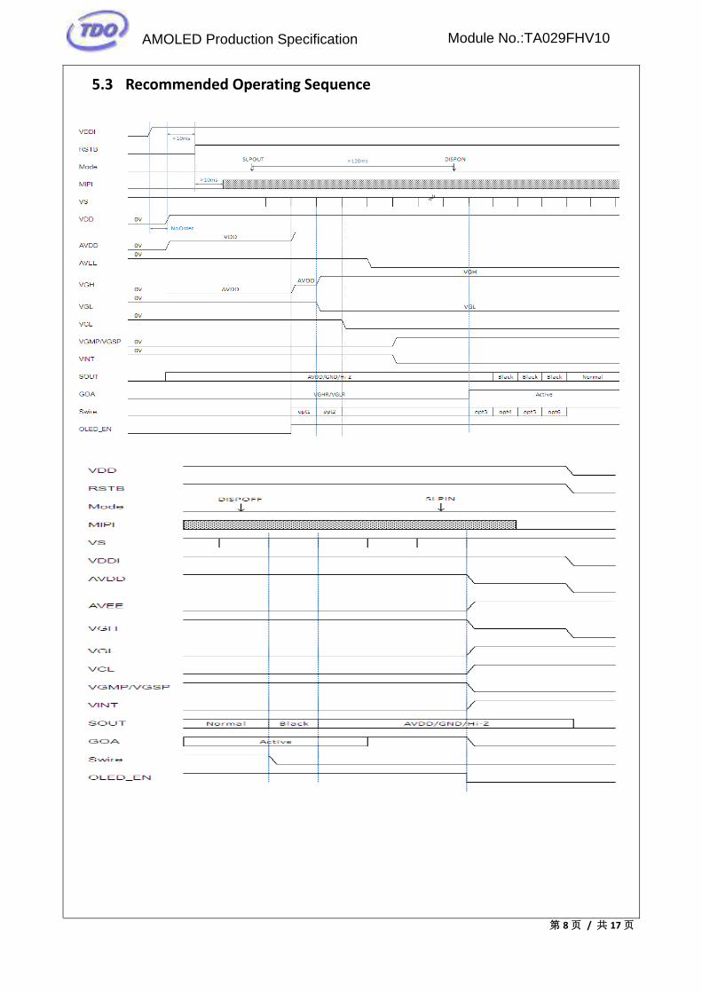
5.3 Recommended Operating Sequence
AMOLED Production Specification Module No.:TA029FHV10

第 9 页 / 共 17 页
5.4 AC Characteristics(MIPI)
5.4.1 HS Data Transmission Burst
5.4.2 HS Clock Transmission
5.4.3 Turnaround Procedure
AMOLED Production Specification Module No.:TA029FHV10

第 10 页 / 共 17 页
5.4.4 Timing Parameters
Parameter Description Min Typ Max Unit
TCLK-POST
Time that the transmitter continues to
send HS clock after the last associated
Data Lane has transitioned to LP Mode.
Interval is defined as the period from
the end of THS-TRAIL to the beginning of
TCLK-TRAIL.
60ns +
52*UI - - ns
TCLK-TRAIL
Time that the transmitter drives the HS-0
state after the last payload clock bit of
a HS transmission burst.
60 - - ns
THS-EXIT Time that the transmitter drives LP-11
following a HS burst. 300 - - ns
TCLK-TERM-EN
Time for the Clock Lane receiver to
enable the HS line termination, starting
from the time point when Dn crosses
VIL,MAX.
Time for
Dn to
reach
VTERM-EN
- 38 ns
TCLK-PREPARE
Time that the transmitter drives the
Clock Lane LP-00 Line state immediately
before the HS-0 Line state starting the
HS transmission.
38 - 95 ns
TCLK-PRE
Time that the HS clock shall be driven by
the transmitter prior to any associated
Data Lane beginning the transition from
LP to HS mode.
8 - - UI
TCLK-PREPARE +
TCLK-ZERO
TCLK-PREPARE + time that the transmitter
drives the HS-0 state prior to starting
the Clock.
300 - - ns
TD-TERM-EN
Time for the Data Lane receiver to enable
the HS line termination, starting from
the time point when Dn crosses VIL,MAX .
Time for
Dn to
reach
VTERM-EN
- 35 ns
+4*UIns
THS-PREPARE
Time that the transmitter drives the Data
Lane LP-00 Line state immediately before
the HS-0 Line state starting the HS
transmission
40ns +
4*UI -
85 ns +
6*UI ns
THS-PREPARE +
THS-ZERO
THS-PREPARE + time that the transmitter
drives the HS-0 state prior to
transmitting the Sync sequence.
145ns +
10*UI -
85ns+6*
UI ns
THS-TRAIL
Time that the transmitter drives the
flipped differential state after last
payload data bit of a HS transmission
burst
60ns +
4*UI - - ns
AMOLED Production Specification Module No.:TA029FHV10

第 11 页 / 共 17 页
5.4.5 Timing requirements for RESETB
When RESETB of the reset pin equals to Low, it will be in the condition of reset.
When it is in the condition of reset, it will make the device recover the initial set.
However, in order to avoid the reset noise cause reset, there is a mechanism to judge about
whether the reset is needed or not. The closed interval of Low can be shown as the following.
Figure: Reset timing
(Test condition: VDDIO=1.65V~3.6V, VSS=0V, TA=-20℃~+85℃)
Symbol Parameter Related
Pins
Spec Note Unit
Min. Typ. Max.
TRESW Reset low
pulse width RESX 10 us
TREST Reset
complete time
- 5 When reset applied
during Sleep in mode ms
- 120 When reset applied
during Sleep out mode ms
Table: Reset timing
5.5 Scan Direction
AMOLED Production Specification Module No.:TA029FHV10

第 12 页 / 共 17 页
6 Electro-Optical Specification
Item Symbol Conditions Min. Typ. Max. Unit Remark
Brightness
Note1
120 132- cd/m2
Note2 Brightness Uniformity 75 - %
Contrast Ratio CR 10,000 - -
CIE
Chro
mati
city
White x
Normal to surface
(0.28) (0.3) (0.32) -
y (0.29) (0.31) (0.33) -
Red x (0.63) (0.66) (0.69) -
y (0.31) (0.34) (0.37) -
Green x (0.16) (0.21) (0.26) -
y (0.68) (0.73) (0.78) -
Blue x (0.09) (0.13) (0.17) -
y (0.02) (0.06) (0.10) -
Color Gamut vs. NTSC 80 105 - %
Viewing angle U/D/L/R CR≥200 80 - °
Cross-talk 4% black or white
window, 117 gray scale - - 5 % Note3
Gamma V(Gray)=48,72,104,132,
164,192,224,255 2.0 2.2 2.4 -
Response time - - 2 ms Note 4
Note1: Temp.25℃,(Angle、distance)
Environmental conditions:Temp.25℃±3℃,65±20%RH,Dark Room。
Distance of OLED display center to measuring machine is 50cm。
Note2: Brightness, Brightness Uniformity and Contrast Ratio definition
Measure 5 points of Display Brightness. P1~P5.
AMOLED Production Specification Module No.:TA029FHV10

第 13 页 / 共 17 页
1) Brightness definition
Luminance = [ P1 + P2 + P3 + P4 + P5 ] / 5
2) Brightness Uniformity definition
Brightness Uniformity = Y(min) / Y(max)
3) Contrast Ratio definition
Dark Room C.R= Luminance (White) / Luminance (Black)
Note3: Cross-talk
4% black or white window ,117 gray background.
LW_OFF =Lw1+Lw2+Lw3+Lw4
4LB_OFF =
LB1+LB2+LB3+LB4
4
CT =|LWi_ON − LW_OFF|
LW_OFF× 100%(i = 5 𝑡𝑜 8)
For white windows AWi (i = 5 to 8), and
CT =|LBi_ON − LB_OFF|
LB_OFF× 100%(i = 5 to 8)
For black windows ABi (i = 5 to 8).
The maximum cross-talk value shall be noted in the measurement report.
Note4: Response Time
Response time=Pixel turn on and turn off time (White<=>Black).
It is measuring transition time from 10% to 90% of luminance.
AMOLED Production Specification Module No.:TA029FHV10

第 14 页 / 共 17 页
7 Reliability
7.1 Environmental Test
No Item Conditions(Note1)
1 High Temperature Operation 60℃ / 128 hours
2 High Temperature non-Operation 70℃ / 128 hours
3 Low Temperature Operation -20℃ / 128 hours
4 Low Temperature non-Operation -30℃ / 128 hours
7.2 Electrical Test
No Item Conditions
1 Air discharge ±4KV,150PF/330Ω (Module level)
2 Contact discharge ±3KV, 150PF/330Ω (Module level)
AMOLED Production Specification Module No.:TA029FHV10

8. Outline Dimension Drawing
AMOLED Production Specification Module No.:TA029FHV10
43
21
56
78
A
D
43
21
67
8
Date:(日期)
Pag
e:(页数)
1/1
图纸视角:
DES
IGN:
(设计)
CHE
CKED:(检查)
APPROVED:(批准)SPECIFICATION
规 格
01
EDI
TION
:(版本号)
CUSTOMER'S CODE:(客户型号)
EDITION:(版本号)
TDO'S CODE:(冠显料号)
客户名称
承认日期
承认
请 签
回 此
图
签 暑
标示
日 期
更改内容
上海冠显光电科技有限公司

第 16 页 / 共 17 页
9 Handing Precautions
9.1 When cleaning ITO pad, avoid using hard and abrasive material or corrosive solution.
9.2 Keep module away from direct sunlight or fluorescent light, and keep it at room
temperature and humidity.
9.3 Strong impact & pressure on module and packing is prohibited.
9.4 Following normal power on/off sequence is necessary for preventing abnormal display or
permanent damage to display.
9.5 Optimal contrast ratio under ideal voltage is AMOLED module’s characteristic, hence it is
recommended a voltage control function available.
9.6 Image sticking may occur if an image displays for an extended period of time.
9.7 When interfered by system’s overall mechanical design, an abnormal display may occur.
9.8 After considering emitting energy, you should plan your design to satisfy EMI standards.
9.9 Host side should place a surge-prevent circuit at power trace (ie: VCI, Vddi) to protect
AMOLED module.
10 Packing Specification
NO 料号 品名 材料 尺寸(mm) 数量(个) 备注1 TA029FHV10 TA029FHV10 FOG 52.912*62.58*0.653 1802 16.13001.010/020 外箱标签 纸 52*100*0.1 13 16.13002.010/020 内箱标签 纸 52*100*0.075 24 21.13129.010/020 吸塑盘 PET 455*290*14 205 21.13130.010/020 EPE-Spacer EPE 395.24*220.46*1 366 21.13011.010/020 EPE填充物(规格2) EPE 395.24*220.46*1 47 21.13003.010/020/30 纸箱 纸 516*338*248 18 21.13004.010/020/30 纸盒 纸 459*294*115 29 21.13005.010/020 干燥剂 干燥剂 55*75 410 21.13006.010/020/30 静电防尘袋 PE 660*440*0.28 211 21.13010.010/020/30 PP 板 PP 457*292*5 212 21.13012.010/020/30 EPE护角 EPE 120*244*100 413 TBD 栈板 木材 TBD 1/30
1. 整箱材料说明
每列的产品数量2个X每行的产品数量5个=10个整个吸塑盘的产品数量10个X包装产品的吸塑盘数量9个(不包括最上方的空盘)=90 个整个纸盒的产品数量90个X包装产品的纸盒数量2个=180个整箱产品数量180个X纸箱的数量30个=5400个
2. 整栈板产品数量说明(1)整个吸塑盘的产品数量(2)整个纸盒的产品数量(3)整个纸箱的产品数量(3)整个栈板的产品数量
AMOLED Production Specification Module No.:TA029FHV10