Production process 1 (Dec 2019) Q1) (a) Draw and discuss ...
20
Production process 1 (Dec 2019) Q1) (a) Draw and discuss working of explosive welding techniques with its applications, advantages and limitations. (10) SOLUTION: Explosive welding can be considered as a kind of hot-pressing. Explosion welding develops an extremely high pressure for a short time. The surfaces to be joined are brought together at very high speed. The impact energy plasticizes them and produces a good welded bond. The amount of heat developed is modest. As opposed to other processes, such as those involving melting of the materials, there is no (or only an insignificant) melt zone in which materials from the two pieces can be mixed or can chemically react with each other. Explosion welding of larger pieces must be performed at specially designated sites. Application: Explosion welding is used primarily for preparing blanks or billets, although it can also be used for such applications as joining pipes or securing tubes in tubeplates. The method is often used for a combination of materials that are difficult to join using other methods. An example of such an application is the bonding of aluminum sections to steel, on which it is then possible to use ordinary welding methods to add further aluminum components, e.g. the superstructure of a vessel, made of aluminum, on a steel hull. Advantages: Explosion welding can produce a bond between two metals that cannot necessarily be welded by conventional means. The process does not melt either metal, instead plasticizing the surfaces of both metals, causing them to come into intimate contact sufficient to create a weld. This is a similar principle to other non-fusion welding techniques, such as friction
Transcript of Production process 1 (Dec 2019) Q1) (a) Draw and discuss ...
Production process 1
(Dec 2019)
Q1)
(a) Draw and discuss working of explosive welding techniques with its applications,
advantages and limitations. (10)
SOLUTION:
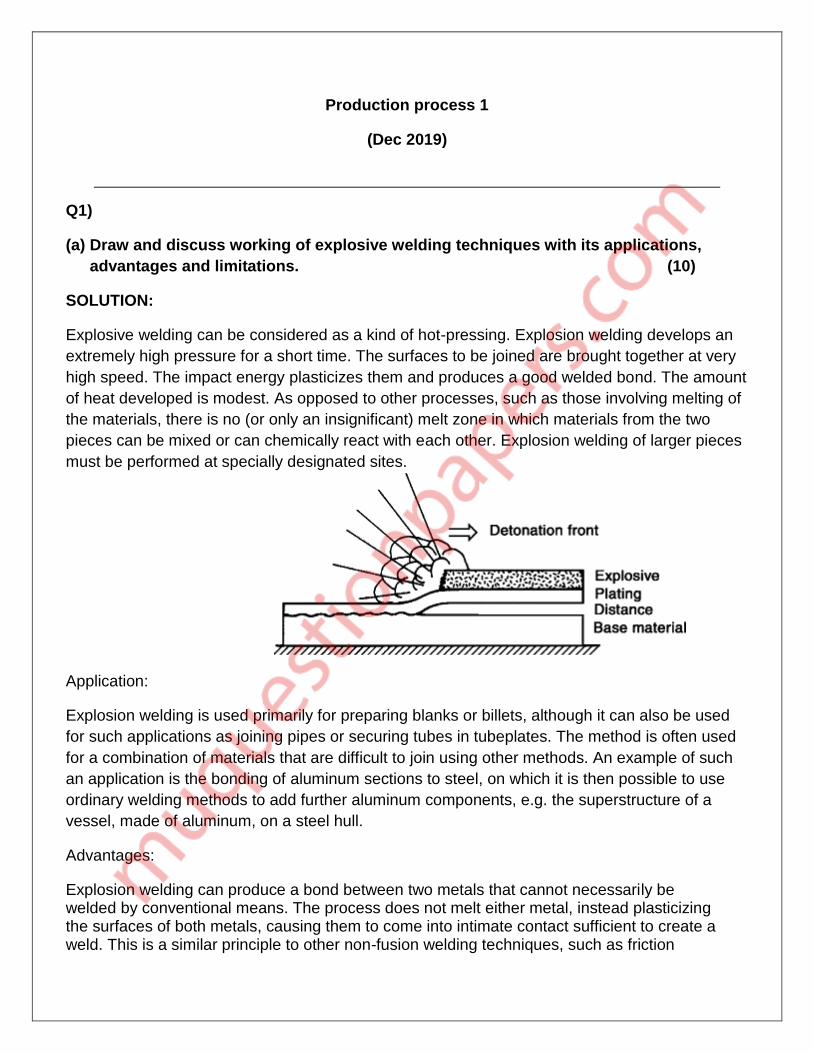
Explosive welding can be considered as a kind of hot-pressing. Explosion welding develops an
extremely high pressure for a short time. The surfaces to be joined are brought together at very
high speed. The impact energy plasticizes them and produces a good welded bond. The amount
of heat developed is modest. As opposed to other processes, such as those involving melting of
the materials, there is no (or only an insignificant) melt zone in which materials from the two
pieces can be mixed or can chemically react with each other. Explosion welding of larger pieces
must be performed at specially designated sites.
Application:
Explosion welding is used primarily for preparing blanks or billets, although it can also be used
for such applications as joining pipes or securing tubes in tubeplates. The method is often used
for a combination of materials that are difficult to join using other methods. An example of such
an application is the bonding of aluminum sections to steel, on which it is then possible to use
ordinary welding methods to add further aluminum components, e.g. the superstructure of a
vessel, made of aluminum, on a steel hull.
Advantages:
Explosion welding can produce a bond between two metals that cannot necessarily be welded by conventional means. The process does not melt either metal, instead plasticizing the surfaces of both metals, causing them to come into intimate contact sufficient to create a weld. This is a similar principle to other non-fusion welding techniques, such as friction

welding. Large areas can be bonded extremely quickly and the weld itself is very clean, due to the fact that the surface material of both metals is violently expelled during the reaction. Explosion welding can join a wide array of compatible and non-compatible metals; with more than 260 metal combinations possible.
Disadvantage:
A disadvantage of this method is that extensive knowledge of explosives is needed before the
procedure may be attempted safely. Regulations for the use of high explosives may require
special licensing.
Q1)
(b) What’s a pattern? How’s it different from casting? Discuss various allowances on
pattern and the material alternatives for pattern making. (10)
SOLUTION:
A pattern is a replica of the object to be cast, used to prepare the cavity into which molten
material will be poured during the casting process. Patterns used in sand casting may be made
of wood, metal, plastics or other materials. Patterns are made to exacting standards of
construction, so that they can last for a reasonable length of time, according to the quality grade
of the pattern being built, and so that they will repeatably provide a dimensionally acceptable
casting.
Difference between pattern and casting
• the main difference between a pattern and the casting is their dimensions.
• A pattern is slightly larger in size as compared to the casting, because a pattern, – carries
Shrinkage allowance, it may be of the order of 1 to 2 mm/ 100 mm. – is given a Machining
allowance to clean and finish the required surfaces. – carries a Draft allowance of the order of 1
and 3 degrees for external and internal surfaces respectively – carries core prints.
• A pattern may not have all holes and slots which a casting will have. Such holes and slots
unnecessarily complicate a pattern and therefore can be drilled in the casting after it has
been made.
• A pattern may be in two or three pieces whereas a casting is in one piece. • A pattern and
the casting also differ as regards the material out of which they are made.
Pattern allowances:
To compensate for any dimensional and structural changes which will happen during the casting
or patterning process, allowances are usually made in the pattern.
1. Shrinkage Allowance: almost all metals shrink or contract volumetrically after solidification to obtain a particular size of casting an amount is equal to the shrinkage or contraction. The metal will undergo shrinkage during solidification and contract further on cooling to room temperature. To compensate this, the pattern is made larger than the required casting. This extra size is given on the pattern for metal shrinkage is called shrinkage allowance.
2. Draft allowance: When the pattern is to be removed from the sand mold, there is a possibility that any leading edges may break off, or get damaged in the process. To avoid this, a taper is provided on the pattern, so as to facilitate easy removal of the pattern from the mold, and hence reduce damage to edges.
3. Finishing or Machining allowance: During machining processes, some metal is removed from the piece. To compensate for this, a machining allowance (additional material) should be given in the casting.
4. Shake allowance: Usually during removal of the pattern from the mold cavity, the pattern is rapped all around the faces, in order to facilitate easy removal. In this process, the final cavity is enlarged. To compensate for this, the pattern dimensions need to be reduced.
5. Distortion allowance: During cooling of the mould, stresses developed in the solid metal may induce distortions in the cast. This is more evident when the mould is thinner in width as compared to its length. This can be eliminated by initially distorting the pattern in the opposite direction.
____________________________________________________________________________
Q2)
(a) Draw and explain geometry of a single point cutting tool. (10)
SOLUTION:
A tool that has a single point for cutting purpose is called single point cutting tool. It is generally
used in the lathe machine, shaper machine etc. It is used to remove the materials from the work
piece.
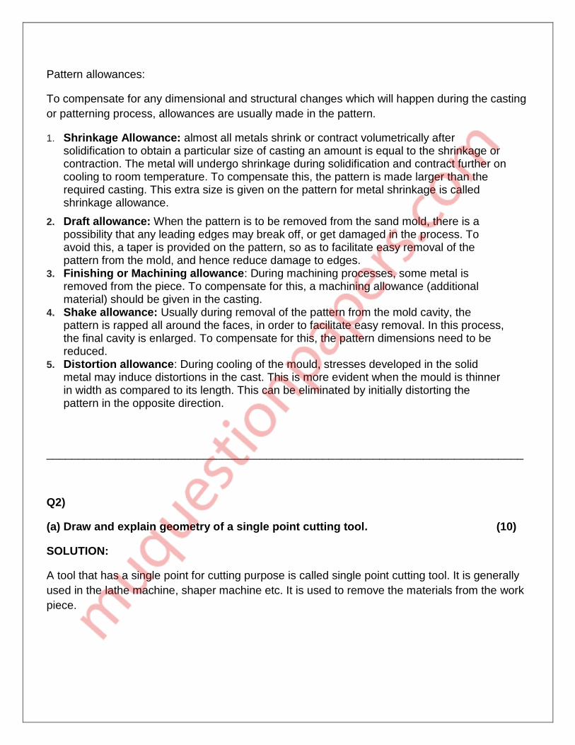
1. Shank: It is that part of single point cutting tool which goes into the tool holder. Or in simple language shank is used to hold the tool. 2. Flank: It is the surface below and adjacent of the cutting edges. There are two flank surfaces, first one is major flank and second one is minor flank. The major flank lies below and adjacent to the side cutting edge and the minor flank surface lies below and adjacent to the end cutting edge. 3. Base: The portion of the shank that lies opposite to the top face of the shank is called base. 4. Face: It is the top portion of the tool along which chips slides. It is designed in such a way that the chips slides on it in upward direction. 5. Cutting edge: The edge on the tool which removes materials from the work piece is called cutting edges. It lies on the face of the tool. The single point cutting tool has two edges and these are (i) Side cutting edge: The top edge of the major flank is called side cutting edge. (ii) End cutting edge: The top edge of the minor flank is called end cutting edge. 6. Nose or cutting point: The intersection point of major cutting edge and minor cutting edge is called nose. 7. Nose radius: It is the radius of the nose. Nose radius increases the life of the tool and provides better surface finish. 8. Heel: It is a curved portion and intersection of the base and flank of the tool.
Angles of Single Point Cutting Tool The various angles of the single point cutting tool have great importance. Each angle has its own function and specialty.
1. End Cutting Edge Angle: The angle formed in between the end cutting edge and a line perpendicular to the shank is called end cutting edge angle.
2. Side Cutting Edge Angle: The angle formed in between the side cutting edge and a line parallel to the shank.
3. Back Rack Angle: The angle formed between the tool face and line parallel to the base is called back rake angle.
4. End Relief Angle: The angle formed between the minor flank and a line normal to the base of the tool is called end relief angle. It is also known as front clearance angle. It avoids the rubbing of the work piece against tool.
5. Lip Angle/ Wedge Angle: It is defined as the angle between face and minor flank of the single point cutting tool.
6. Side Rake Angle: the angle formed between the tool face and a line perpendicular to the shank is called side rake angle.
7. Side Relief Angle: the angle formed between the major flank surface and plane normal to the base of the tool is called side relief angle. This angle avoids the rubbing between work piece and flank when the tool is fed longitudinally.
Q2)
(b)Explain working of submerged Arc Welding with its applications, advantages and
limitations. (10)
SOLUTION:
The definition of submerged arc welding is, it is one type of welding method where this
welding arc can travel under a layer of granular flux. In this type of welding, a tubular
electrode otherwise consumable solid can be fed constantly to the weld region. At the
same time, a layer of granular fusible flux can be poured over the weld zone which
immersed the welding arc as well as defends it from atmospheric pollution.
The granulated flux includes compounds like lime, silica, manganese oxide, calcium
fluoride, etc. Whenever the flux is melted, then it turns into conductive as well as offers
a current lane among the work piece & electrode. The solid layer of flux wraps the
melted metal totally and stops the sprinkle and covers the strong ultraviolet (UV)
radiation vapors generated during the procedure.

Submerged Arc Welding Working
In this kind of welding, the flux begins for depositing on the joint to be welded.
Whenever the flux is cold, then it acts as an insulator. The arc can be started by moving
the tool by the work portion. The arc struck will constantly remain below a wide coating
of flux, and the generated heat by the arc softens the granular flux.
Once the flux is melted by the heat of the arc, then it will become highly conductive. The
flow of current begins to flow the electrode through the melted flux that can be in contact
by the atmosphere. The minor dissolved flux alters to wastage slag & which is detached
after welding method finished.
At a fixed speed, the electrode from the roll is constantly fed toward the joint to be
linked. If linking is partially automatic, then the top of the welding can be moved
physically along with the connection. In an automatic submerged arc welding, a
separate drive can be used to move the welding top above the stationary job otherwise
job moves beneath the head of the stationary welding.
With the help of the self-adjusting arc principle, the length of the arc is kept stable.
When the arc length reduces, the arc voltages will increase & this will increase the arc
current.
Because of this, the rates of burn-off will increase & the arc length will be increased.
The reverse phenomenon arises when the arc length rises more than the regular length.

For straight penetration as well as for supporting the huge quantity of melted metal a
support steel plate otherwise copper may be used.
Advantages
This submerged arc welding process has high (45kg/h) deposit rate. In automatic applications. Very small welding smoke can be observed. No edge training is required. This method is used in indoor, and outdoor. No chance of weld sprinkles because it is submerged within flux blanket.
Disadvantages
The process is incomplete to some particular metals. The application is imperfect to direct seams vessels, and pipes. The flux usage is hard. A health problem can be occurred due to the flux. Slag elimination is desirable after welding. Applications The Submerged Arc Welding can be used to weld pressure vessels like boilers. A lot of structural outlines, pipes, earth moving tools, shipbuilding, railroad
construction, and locomotives. This type of welding can be used to repair machine parts.
____________________________________________________________________________
Q3)
(a)Discuss physics of electric welding arc with the help of diagrams. (10)
SOLUTION:
Arc welding is a welding process that is used to join metal to metal by using electricity to create enough heat to melt metal, and the melted metals when cool result in a binding of the metals. It is a type of welding that uses a welding power supply to create an electric arc between a metal stick ("electrode") and the base material to melt the metals at the point of contact. Arc welders can use either direct (DC) or alternating (AC) current, and consumable or non-consumable electrodes.
The welding area is usually protected by some type of shielding gas, vapor, or slag. Arc welding processes may be manual, semi-automatic, or fully automated. First developed in the late part of the 19th century, arc welding became commercially important in

shipbuilding during the Second World War. Today it remains an important process for the fabrication of steel structures and vehicles.
Any arc welding method is based on an electric circuit consisting of the following parts:
Power supply (AC or DC);
Welding electrode;
Work piece;
Welding leads (electric cables) connecting the electrode and work piece to the
power supply.
Working:
Electric arc between the electrode and work piece closes the electric circuit. The arc temperature may reach 10000°F (5500°C), which is sufficient for fusion the work piece edges and joining them.
When a long join is required the arc is moved along the joint line. The front edge of the weld pool melts the welded surfaces when the rear edge of the weld pool solidifies forming the joint. When a filler metal is required for better bonding, filling rod (wire) is used either as outside material fed to the arc region or as consumable welding electrode, which melts and fills the weld pool. A chemical composition of filler metal is similar to that of work piece.

Molten metal in the weld pool is chemically active and it reacts with the surrounding atmosphere. As a result weld may be contaminated by oxide and nitride inclusions deteriorating its mechanical properties. Neutral shielding gases (argon, helium) and/or shielding fluxes are used for protection of the weld pool from atmospheric contamination. Shields are supplied to the weld zone in form of a flux coating of the electrode or in other forms.
Q3) (b)Explain the working principle of resistance spot welding process with the help of
diagrams. (10)
SOLUTION:
Resistance spot welding (RSW) is a process in which contacting metal surface points are joined by the heat obtained from resistance to electric current. It is a subset of electric resistance welding.
Work-pieces are held together under pressure exerted by electrodes. Typically the sheets are in the 0.5 to 3 mm (0.020 to 0.118 in) thickness range. The process uses two shaped copper alloy electrodes to concentrate welding current into a small "spot" and to simultaneously clamp the sheets together. Forcing a large current through the spot will melt the metal and form the weld. The attractive feature of spot welding is that a lot of energy can be delivered to the spot in a very short time (approximately 10–100 milliseconds).That permits the welding to occur without excessive heating of the remainder of the sheet.
The amount of heat (energy) delivered to the spot is determined by the resistance between the electrodes and the magnitude and duration of the current. The amount of energy is chosen to match the sheet's material properties, its thickness, and type of electrodes. Applying too little energy will not melt the metal or will make a poor weld. Applying too much energy will melt too much metal, eject molten material, and make a hole rather than a weld. Another feature of spot welding is that the energy delivered to the spot can be controlled to produce reliable welds.
Working:Spot welding involves three stages; the first of which involves the electrodes being brought to the surface of the metal and applying a slight amount of pressure. The current from the electrodes is then applied briefly after which the current is removed but the electrodes remain in place for the material to cool. Weld times range from 0.01 sec to 0.63 sec depending on the thickness of the metal, the electrode force and the diameter of the electrodes themselves.
The equipment used in the spot welding process consists of tool holders and electrodes. The tool holders function as a mechanism to hold the electrodes firmly in place and also support optional water hoses that cool the electrodes during welding. Tool holding methods include a paddle-type, light duty, universal, and regular offset. The electrodes generally are made of a low resistance alloy, usually copper, and are designed in many different shapes and sizes depending on the application needed.
The two materials being welded together are known as the work pieces and must conduct electricity. The width of the work pieces is limited by the throat length of the welding apparatus and ranges typically from 5 to 50 inches (13 to 130 cm). Work piece thickness can range from 0.008 to 1.25 inches (0.20 to 32 mm).
After the current is removed from the work piece, it is cooled via the coolant holes in the center of the electrodes. Both water and a brine solution may be used as coolants in spot welding mechanisms.
____________________________________________________________________________
Q4)
(a) Explain the imposition of directional solidification in sand casting. (10)
SOLUTION:
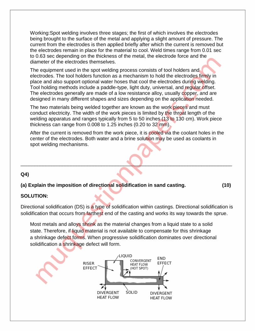
Directional solidification (DS) is a type of solidification within castings. Directional solidification is
solidification that occurs from farthest end of the casting and works its way towards the sprue.
Most metals and alloys shrink as the material changes from a liquid state to a solid
state. Therefore, if liquid material is not available to compensate for this shrinkage
a shrinkage defect forms. When progressive solidification dominates over directional
solidification a shrinkage defect will form.

The geometrical shape of the mold cavity has a direct effect on progressive and directional solidification. At the end of tunnel-type geometries, divergent heat flow occurs, which causes that area of the casting to cool faster than surrounding areas; this is called an end effect. Large cavities do not cool as quickly as surrounding areas because there is less heat flow; this is called a riser effect. Also note that corners can create divergent or convergent (also known as hot spots) heat flow areas.
In order to induce directional solidification chills, risers, insulating sleeves, control of pouring rate, and pouring temperature can be utilized.
Directional solidification can be used as a purification process. Since most impurities will be more soluble in the liquid than in the solid phase during solidification, impurities will be "pushed" by the solidification front, causing much of the finished casting to have a lower concentration of impurities than the feedstock material, while the last solidified metal will be enriched with impurities. This last part of the metal can be scrapped or recycled. The suitability of directional solidification in removing a specific impurity from a certain metal depends on the partition coefficient of the impurity in the metal in question, as described by the Scheil equation. Directional solidification (in zone melting) is frequently employed as a purification step in the production of multicrystalline silicon for solar cells.
Q4)
(b) Draw and explain significance of various elements of grating system in sand
casting. (10)
SOLUTION:
Gating system refers to all passageways though which the molten metal passes to enter the
mould cavity.
The characteristics of each element are mentioned below:
Pouring basin: This is otherwise called as bush or cup. It is circular or rectangular in shape. It collects the molten metal, which is poured, from the ladle. A pouring basin makes it easier for the ladle or crucible operator to direct the flow of metal from crucible sprue. It reduces turbulence at the sprue entrance.
Sprue: It is circular in cross section. It leads the molten metal from the pouring basin to the sprue well. A sprue is tapered with its bigger end at top to receive the liquid metal; the smaller end is connected to runner.
Runner: The runner takes the molten metal from sprue to the casting. Ingate: This is the final stage where the molten metal moves from the runner to the mold cavity.
Gates: A gate is channel which connects runner with the mould cavity and through which molted metal flows to fill the mould cavity. A gate should not have sharp edges as they may break during pouring and sand pieces thus may be carried with the molten metal in the mould cavity.
Risers: As a part of the runner system or gating, the riser is an extraneous reservoir cavity of molten metal used to feed the casting as the metal solidifies. The riser is used to compensate for losses due to shrinkage as the casting cools.
____________________________________________________________________________
Q5)
(a) Draw and explain working of screw injection moulding of polymers with its
applications, advantages and limitations. (10)
SOLUTION:
Injection molding is the most commonly used manufacturing process for the fabrication of plastic
parts. A wide variety of products are manufactured using injection molding, which vary greatly in
their size, complexity, and application. The injection molding process requires the use of an
injection molding machine, raw plastic material, and a mold. The plastic is melted in the injection
molding machine and then injected into the mold, where it cools and solidifies into the final part.
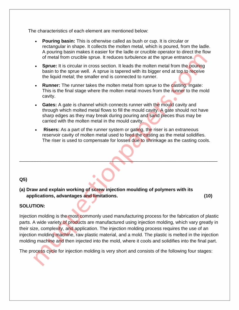
The process cycle for injection molding is very short and consists of the following four stages:
1. Clamping - Prior to the injection of the material into the mold, the two halves of the mold must first be securely closed by the clamping unit. Each half of the mold is attached to the injection molding machine and one half is allowed to slide. The hydraulically powered clamping unit pushes the mold halves together and exerts sufficient force to keep the mold securely closed while the material is injected. The time required to close and clamp the mold is dependent upon the machine - larger machines (those with greater clamping forces) will require more time. This time can be estimated from the dry cycle time of the machine.
2. Injection - The raw plastic material, usually in the form of pellets, is fed into the injection molding machine, and advanced towards the mold by the injection unit. During this process, the material is melted by heat and pressure. The molten plastic is then injected into the mold very quickly and the buildup of pressure packs and holds the material. The amount of material that is injected is referred to as the shot. The injection time is difficult to calculate accurately due to the complex and changing flow of the molten plastic into the mold. However, the injection time can be estimated by the shot volume, injection pressure, and injection power.
3. Cooling - The molten plastic that is inside the mold begins to cool as soon as it makes contact with the interior mold surfaces. As the plastic cools, it will solidify into the shape of the desired part. However, during cooling some shrinkage of the part may occur. The packing of material in the injection stage allows additional material to flow into the mold and reduce the amount of visible shrinkage. The mold cannot be opened until the required cooling time has elapsed. The cooling time can be estimated from several thermodynamic properties of the plastic and the maximum wall thickness of the part.
4. Ejection - After sufficient time has passed, the cooled part may be ejected from the mold by the ejection system, which is attached to the rear half of the mold. When the mold is opened, a mechanism is used to push the part out of the mold. Force must be applied to eject the part because during cooling the part shrinks and adheres to the mold. In order to facilitate the ejection of the part, a mold release agent can be sprayed onto the surfaces of the mold cavity prior to injection of the material. The time that is required to open the mold and eject the part can be estimated from the dry cycle time of the machine and should include time for the part to fall free of the mold. Once the part is ejected, the mold can be clamped shut for the next shot to be injected.
Advantages:
1. High Efficiency- Fast Production
2. Complex Part Design
3. Enhanced Strength
4. Flexibility- Material and Color
5. Reduced Waste
6. Low Labor Costs Disadvantages:
1. The cost of the machines is high.
2. The designs will have to be created before any process can begin.
3. Production behind schedule or cost more money for the company.
4. There are also some limitations to what types of designs can be made with this process.
Applications:
Injection moulding is used to create many things such as wire spools, packaging, bottle caps, automotive parts and components, toys, pocket combs, some musical instruments (and parts of them), one-piece chairs and small tables, storage containers, mechanical parts (including gears), and most other plastic products available today. Injection moulding is the most common modern method of manufacturing plastic parts; it is ideal for producing high volumes of the same object.
Q5)
(b) Draw and explain various operations possible on center lathe. (10)
SOLUTION:
The general operations done with the lathe are grooving, turning, cutting, sanding and etc. if anyone wants to operate the lathe machine then he must first know about the feeds, cutting speed, depth of the cut and usage of tool should be considered.
Each lathe operation has got its own factors that need to be considered before doing the work.
The factors should be used properly so that one can avoid from mishandling and mishaps while performing any kind of lathe operation.
With every cut desired the speed, depth and feed of the lathe machine is changed for precision.
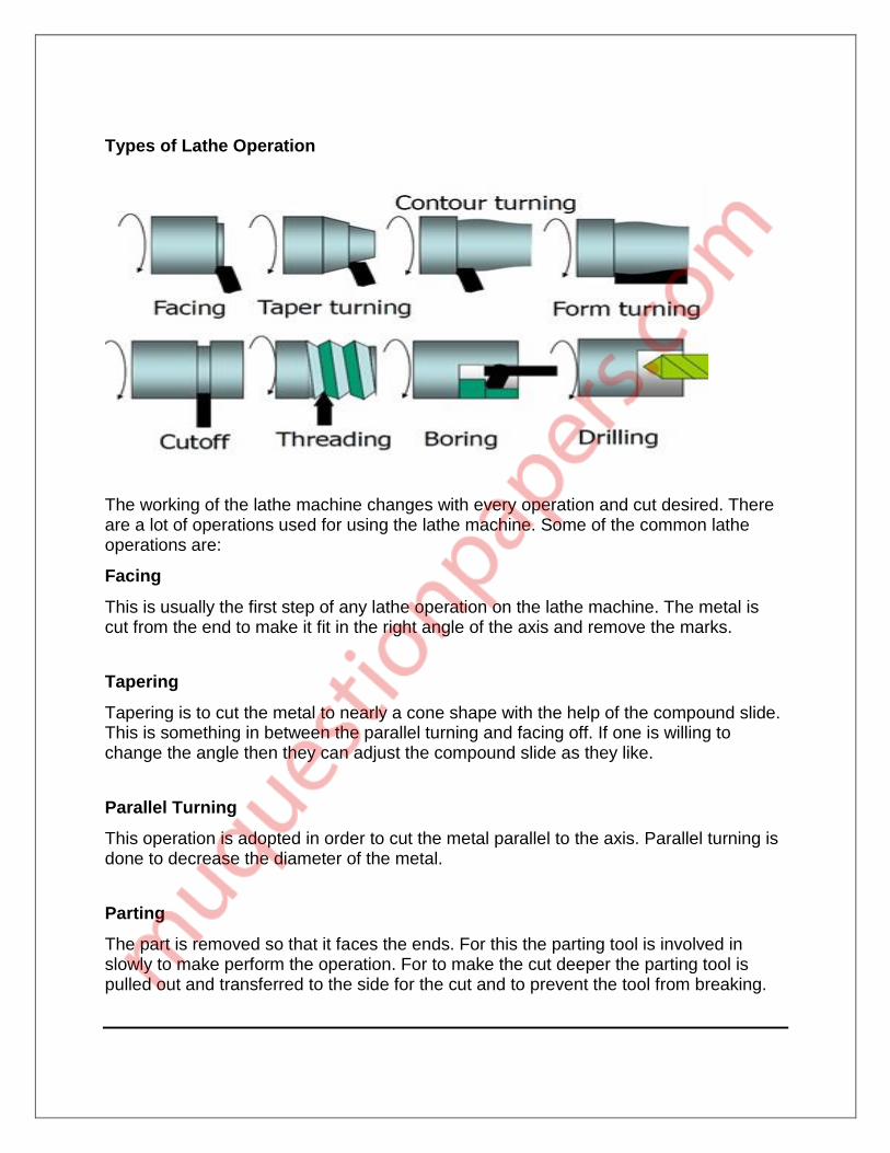
Types of Lathe Operation
The working of the lathe machine changes with every operation and cut desired. There are a lot of operations used for using the lathe machine. Some of the common lathe operations are:
Facing
This is usually the first step of any lathe operation on the lathe machine. The metal is cut from the end to make it fit in the right angle of the axis and remove the marks.
Tapering
Tapering is to cut the metal to nearly a cone shape with the help of the compound slide. This is something in between the parallel turning and facing off. If one is willing to change the angle then they can adjust the compound slide as they like.
Parallel Turning
This operation is adopted in order to cut the metal parallel to the axis. Parallel turning is done to decrease the diameter of the metal.
Parting
The part is removed so that it faces the ends. For this the parting tool is involved in slowly to make perform the operation. For to make the cut deeper the parting tool is pulled out and transferred to the side for the cut and to prevent the tool from breaking.
Q6) Write short note on:
(a) Various soldering techniques (5)
(i) Soldering is a process in which two or more items are joined together by melting and putting a filler metal (solder) into the joint, the filler metal having a lower melting point than the adjoining metal. There are three forms of soldering, each requiring progressively higher temperatures and producing an increasingly stronger joint strength:
1. soft soldering, which originally used a tin-lead alloy as the filler metal
2. silver soldering, which uses an alloy containing silver
3. brazing which uses a brass alloy for the filler
(ii) The alloy of the filler metal for each type of soldering can be adjusted to modify the melting temperature of the filler. Soldering differs from gluing significantly in that the filler metals directly bond with the surfaces of the work pieces at the junction to form an electrically conductive gas- and liquid-tight bond.
(iii) Soft soldering is characterized by having a melting point of the filler metal below approximately 400 °C (752 °F) whereas silver soldering and brazing use higher temperatures, typically requiring a flame or carbon arc torch to achieve the melting of the filler. Soft solder filler metals are typically alloys (often containing lead) that have liquids temperatures below 350 °C (662 °F).
(iv) In this soldering process, heat is applied to the parts to be joined, causing the solder to melt and to bond to the work pieces in a surface alloying process called wetting. A good solder joint produces an electrically-conductive, water- and gas-tight join.
(v) Soldering operations can be performed with hand tools, one joint at a time, or en masse on a production line. Hand soldering is typically performed with a soldering iron, soldering gun, or a torch, or occasionally a hot-air pencil. Sheet metal work was traditionally done with "soldering coppers" directly heated by a flame, with sufficient stored heat in the mass of the soldering copper to complete a joint; gas torches (e.g. butane or propane) or electrically-heated soldering irons are more convenient.
(vi) All soldered joints require the same elements of cleaning of the metal parts to be joined, fitting up the joint, heating the parts, applying flux, applying the filler, removing heat and holding the assembly still until the filler metal has completely solidified. Depending on the nature of flux material used and the application, cleaning of the joint may be required after it has cooled.
(vii) Each solder alloy has characteristics that work best for certain applications, notably strength and conductivity, and each type of solder and alloy has different melting temperatures. The term silver solder denotes the type of solder that is used. Some soft solders are "silver-bearing" alloys used to

solder silver-plated items. Lead-based solders should not be used on precious metals because the lead dissolves the metal and disfigures it.
(b) Pressurized and non-pressurized gating system in founding practice. (5)
There can be two types of gating system.
(a) Non pressurized gating system: - This has a choke at bottom of the sprue having total runner area and in gates area >sprue area. This reduces the turbulence. This is useful for Al and Mg alloys. These have tapered sprue, sprue base well and pouring basin. Sprue : runner : ingate :: 1:4:4
Disadvantages :- -Air inspiration, casting yield is less (b) Pressurized gating system:- In this type, the in gate areas are smallest, thus
maintaining a back pressure. Because of this, the metal is more turbulent and flows full with a minimum air aspiration. This has a higher casting yield. Mostly useful for ferrous castings. Sprue : runner : ingate :: 1:2:1.
(c) The gating system completely controls the molten metal flow. Gating systems can be classified as Pressurized system and Unpressurised system. Gating ratio depends on the nature of the molten metal.
(d) Pressurized system is used for reactive metals like magnesium alloy etc. Unpressurised gating system is used for normal metals such as brass, steel, aluminum alloy, etc. Pressurized system is referred to as “Gate control System”, since ingates controls the flow of metal.
(e) Unpressurised system is referred to as “Choke Control System”, since the choke controls the flow of metal.
(f) In the pressurized system high metal velocity occurs and results in turbulence. In the case of unpressurised system, turbulence is produced and streamline flow is induced.
(g) Pressurized System Consumes less metal and yield is more. Unpressurised system consumes more metal and the yield will be slightly lowered.
(h) In the case of pressurized system, the system will always be full of liquid metal . In the case of unpressurised system flow is not full.
(c) Electron beam welding (5)
Electron-beam welding (EBW) is a fusion welding process in which a beam of high-velocity electrons is applied to two materials to be joined. The work pieces melt and flow together as the kinetic energy of the electrons is transformed into heat upon impact. EBW is often performed under vacuum conditions to prevent dissipation of the electron beam. It works on the principle that when a high-velocity beam of electron that has Kinetic energy strikes the two metal pieces, the kinetic energy of the electron transformed into heat. The intensity of heat produced is so much that it melts the two metal pieces and fuse them together to form a strong weld.

Advantages High welding speed. Welding of dissimilar metal can be done. High weld quality and precision. Less operating cost. Materials with high welding temperatures can be welded easily. Less distortion due to less affected heat zone. The cost of cleaning is negligible. It welds thicker sheets, ranges from .025 mm to 100 mm. It is capable of welding inaccessible joints.
Disadvantages The cost of equipment is very high. High skilled operator is required to operate it. A high vacuum is required. Due to operation in vacuum, large jobs cannot be welded. High safety measures are needed to work with it.
Application It is used in aerospace industries for manufacturing jet components, parts of structures,
transmission parts and sensors. It is used in power generation industries. It is used in space industries to build titanium tanks and sensors. It is used in automobile industries to manufactures transmission systems, gears, and
turbochargers. It used in electrical and electronic industries to manufactures parts of copper structures. The other areas where it is used are nuclear industries, medical, research centers, etc.
(d) Reaction moulding of polymers. (5)
Reaction injection molding (RIM) is similar to injection molding except thermosetting polymers are used, which requires a curing reaction to occur within the mold.
Common items made via RIM include automotive bumpers, air spoilers, and fenders.
The two parts of the polymer are mixed together, usually by injecting them under high pressure into an impinging mixer. Then the mixture is injected under lower pressure into a mold. The mixture is allowed to sit in the mold long enough for it to expand and cure.[1]
If reinforcing agents are added to the mixture then the process is known as reinforced reaction injection molding (RRIM). Common reinforcing agents include glass fibers and mica. This process is usually used to produce rigid foam automotive panels.
A subset of RIM is structural reaction injection molding (SRIM), which uses fiber meshes for the reinforcing agent. The fiber mesh is first arranged in the mold and then the polymer mixture is injection molded over it.
The most common RIM processable material is polyurethane (known generally as PU-RIM. The bi-component mixture injected into the mold has a much lower viscosity than molten thermoplastic polymers, therefore large, light-weight, and thin-walled items can
be successfully RIM processed. This thinner mixture also requires less clamping forces, which leads to smaller equipment and ultimately lower capital expenditures. Another advantage of RIM processed foam is that a high-density skin is formed with a low-density core.
The disadvantages are slow cycle times, compared to injection molding, and expensive raw materials.
(e) Classification of manufacturing processes. (5)
Classification of the Manufacturing Process:
(1) The manufacturing process used in engineering industries basically perform one or more of the following functions: Change the physical properties of the work material Change the shape and size of the work piece. Produce desired dimensional accuracy and surface finish.
(2) Based on the nature of work involved these processes may be divided into following seven categories:
1. Processes for changing physical properties of the materials – Hardening, Tempering, Annealing, and Surface Hardening.
2. Casting Processes – Sand Casting, Permanent mold casting, die casting, Centrifugal casting
3. Primary metal working processes – Rolling, forging, extrusion, wire drawing 4. Shearing and Forming processes – Punching, blanking, drawing, bending,
forming 5. Joining processes – Welding, brazing, soldering, joining 6. Machining Processes – Turning, drilling, milling, grinding 7. Surface finishing processes – Lapping, honing, super finishing
(3) Constant mass process :
i. Casting: Die casting, centrifugal, slush casting etc.
ii. Metal forming process: Forging, rolling, extrusion, drawing etc.
iii. Powder metallurgy
iv. Heat Treatment: Annealing, case hardening etc.
(4) Metal removal process :
i. Machining: Turning, drilling, milling, shaping, sawing etc.
ii. Grinding, finishing: Cylindrical grinding, sandering, polishing, buffing etc.
iii. Non-conventional process: ECM, EDM etc.
(5) Material addition process :
i. Welding
ii. Mechanical joining: Screwing, riveting, bolting etc.
(f) Quick return mechanism on shaper. (5)
(1) A quick return mechanism is an apparatus to produce a reciprocating motion in which the time taken for travel in return stroke is less than in the forward stroke. It is driven by a circular motion source (typically a motor of some sort) and uses a system of links with three turning pairs and a sliding pair.
(2) Quick return is a common feature of tools in which the action is performed in only one direction of the stroke, such as shapers and powered saws, because it allows less time to be spent on returning the tool to its initial position.
(3) Quick return means short time during return stroke as return process is idle. The shaping machine does all the work in cutting/forward stroke, so as to save time and increase efficiency return strike is kept smaller.
(4) The disc influences the force of the arm, which makes up the frame of reference of the quick return mechanism. The frame continues to an attached rod, which is connected to the circular disc. Powered by a motor, the disc rotates and the arm follows in the same direction (linear and left-to-right, typically) but at a different speed.
(5) When the disc nears a full revolution, the arm reaches its furthest position and returns to its initial position at a quicker rate, hence its name. Throughout the cut, the arm has a constant velocity. Upon returning to its initial position after reaching its maximum horizontal displacement, the arm reaches its highest velocity.
(6) The quick return mechanism was modeled after the crank and slider (arm), and this is present in its appearance and function; however, the crank is usually hand powered and the arm has the same rate throughout an entire revolution, whereas the arm of a quick return mechanism returns at a faster rate. The "quick return" allows for the arm to function with less energy during the cut than the initial cycle of the disc.
_________________________________________________________________________