production of pipe supports and hangers - Moravia Systems
28
PRODUCTION OF PIPE SUPPORTS AND HANGERS
Transcript of production of pipe supports and hangers - Moravia Systems

production of pipe supports and hangers


About us
Scope of engineering services and consulting available
Manufacturing of pipe supports and hangers
Modern machinery
professional packaging, labbeling and own stock
Summary of products made by Moravia Systems
Supports
Guides
piping attachments - Clamps, lugs and U-bolts
Fixed hangers
Spring type hangers and supports
Rigid struts
Supports for non-metal piping
production and supply of customised pipe equipmet
References
2
3
4
5
6
7
8
9
10
11
11
12
12
14
16
contents

ABoUt Us
AssoRtMent oF coMponents, WHIcH YoU cAn FInD In oUR cAtALoGUe oF pIpe sUppoRts AnD HAnGeRs:
1. Supports2. Guides 3. pipe attachments – clamps and U-bolts4. Hanger rods – threaded connecting elements 5. Structural attachment elements6. Support plates, trapezes 7. Rigid struts 8. Supports for non-metal pipelines
The company Moravia Systems a.s. is a member of the strong investment group KKCG. Our path on the Czech market started in 1992 when Karel Komárek founded our company as a wholesale of industrial valves for distribution systems of gas or water. Now we supply valves and accessories, pipes, fl anges, fi ttings and pipe parts to our customers in various in-dustrial domains, e.g. power, petrochemical or chemi-cal industries. Based on our own development and according to our own drawing documentation we have started to ma-nufacture and supply components of pipe supports, especially supports and hangers, complete sets of pipe hangers or special support designs for pre-insu-lated or for cryogenic pipes.
2

3
scope oF enGIneeRInG seRVIces AnD consULtInG AVAILABLe
We benefi t from our in-house team staffed with profes-sional piping engineers based in Brno, gathering experien-ced masters with highly positive references in the fi eld of designing and engineering.
They focus on further development of the product range encompassing pipe fi ttings, analyses of pipe projects, engineering of pipelines, designs of pressure vessels and containers, drafts and drawings of pipe fi tting applications.
1 2 pRocessInG oF pIpe pRoDUctIon DocUMents
• processing of isometric drawingsfor piping
• material specifi cations, specifi ca-tions of supports and hangers
3 pRocessInG oF DesIGns AnD DRAWInG DocUMents FoR pIpInG sUppoRt AnD HAnGeRs AsseMBLIes
• effi cient processing of documen-tation using DWG from compo-nent libraries
• analyses for auxiliary structuresin compliance with EN 1993
stRUctURAL AnD ResILIence AnALYses
oF pIpInG sYsteMs
• duct optimisation with respect to thermal expansions and loadson connected equipment (turbi-nes, pumps, compressors, pressurevessels necks etc.)
• static and dynamic analyses, oscillation and vibration analyses,two-phase fl ow piping
• analyses for both metal and non--metal piping (GRp, HDpE, pp)
3 pRocessInG 3 pRocessInG 3 pRocessInG pRocessInG oF DesIGns AnD 3 oF DesIGns AnD 3 oF DesIGns AnD oF DesIGns AnD DRAWInG DocUMents 3 DRAWInG DocUMents 3 DRAWInG DocUMents DRAWInG DocUMents FoR pIpInG sUppoRt FoR pIpInG sUppoRt AnD HAnGeRs AnD HAnGeRs AsseMBLIes
• effi cient processing of documen-tation using DWG from compo-nent libraries
• analyses for auxiliary structuresin compliance with EN 1993

MAnUFActURInG oF pIpe sUppoRts AnD HAnGeRsThe supports and hangers range by Moravia Systems has been designed pursuant twenty-years of experien-ce with pipe engineering, complemented with thorough knowledge of process reliability issues.
The products are based on the well-known and proven structures, subject to later re-engineering and optimisation as a whole with diligent attention to details.
Our products are made from materials compliant with EN and ASTM – carbon-, alloy- and corrosion-resistant steel. Surface finishing methods employed at our facilities inclu-de coating and galvanizing in order to meet the corrosive environment specifications up to the level C5 identified by EN ISO 12944.
4

5
MoDeRn MAcHIneRY
The manufacturing plant of Moravia Systems situated in Vra-cov is equipped with facilities for forming, splitting, welding and assembly of various materials.
The production and storage premises amount to approx. 4,500 m2. The production process has integrated the quali-ty control systems compliant with EN ISO3834-2, EN 1090-2, MSS-Sp 58.
The company Moravia Systems holds certifications required for steel structure welding, as specified by EN ISO 3834-2.
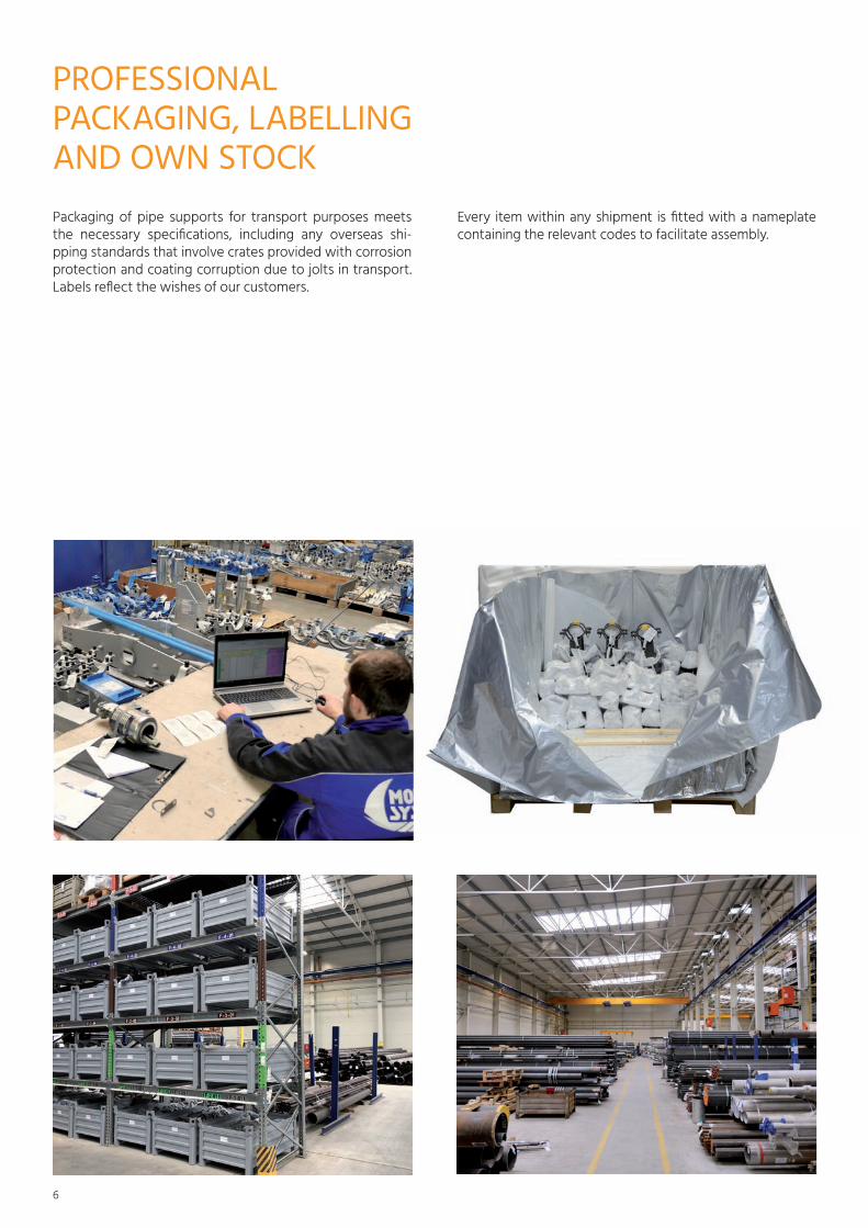
pRoFessIonAL pAcKAGInG, LABeLLInG AnD oWn stocKpackaging of pipe supports for transport purposes meets the necessary specifications, including any overseas shi-pping standards that involve crates provided with corrosion protection and coating corruption due to jolts in transport. Labels reflect the wishes of our customers.
Every item within any shipment is fitted with a nameplate containing the relevant codes to facilitate assembly.
6

7
sUMMARY oF pRoDUcts MADe BY MoRAVIA sYsteMs1. SpRING TYpE pIpE HANGERS Fully assembled sets delivered with springs of variable or constant force manufactured by Lisega. Hanger rods, clamps, U-bolts and supports supplied from our own product range.
2. FIXED HANGERS Fully assembled sets delivered from our own product range.
3. SUppORTS AND GUIDESLarge variety of standard structures available from our own product range.
4. STRUCTURAL ATTACHMENT ELEMENTS Large variety of standard elements available from our own product range.
5. SUppORTS FOR pLASTIC, pRE-INSULATED AND CRYOGENIC pIpES Sets with sliding or roller supports.

sUppoRts
21-3
Short support of standard or optional length. Support length optional within the interval from 0.5×H to 1×H.
B
OD
C
T1
LG
HH
bT2
LABeLLInG
21-3 MS-DNK-H-KP Labelling example: 21-34-073-170
DNK – pipe external diameter specifi cationH – required support heightMS – material category specifi cationKP – sliding surface specifi cation
AsseMBLY
Support assembly involves screwing the sleeves down and tightening of their bolts by 180° once touching down on sleeve surface.
OD DNK H B C L Hb T1 T2 G Fp mmm mm mm mm mm mm mm mm mm mm kN kg21,3 015 100 40 30 100 82 6 6 80 1,1 0,8826,9 020 100 40 30 100 79 6 6 80 1,1 0,8931,8 025 100 40 30 100 77 6 6 80 1,2 0,9033,7 025 100 40 30 100 76 6 6 80 1,2 0,9038 038 120 40 30 100 94 6 6 80 1,0 1,05
42,4 032 120 40 30 100 91 6 6 80 1,0 1,0548,3 040 120 40 30 100 88 6 6 80 1,0 1,0557 057 155 50 40 150 117 8 8 100 1,9 2,2
60,3 050 155 50 40 150 115 8 8 100 1,9 2,273 073 165 50 40 150 119 8 8 100 1,8 2,3
76,1 065 165 50 40 150 117 8 8 100 1,8 2,488,9 080 170 50 40 150 116 8 8 100 1,8 2,4108 108 200 60 50 200 135 10 10 130 2,5 4,2114,3 100 200 60 50 200 131 10 10 130 2,5 4,2127 127 220 80 50 200 145 10 10 130 2,4 4,7133 133 220 80 50 200 142 10 10 130 2,4 4,7
139,7 125 220 80 50 200 139 10 10 130 2,4 4,8141,3 141 220 80 50 200 138 10 10 130 2,4 4,8159 159 240 80 50 200 149 10 10 130 2,3 5,1
168,3 150 240 80 50 200 144 10 10 130 2,3 5,1
DIMensIons AnD specIFIcAtIons
• Sliding support• Sliding support with a guide• Spring support• Clamped support (single/double clamp designs)• Weld-neck support • Anchor
8

9
MS No. 1 2 3 4 5 6 7Tmax (°C) 350 500 580 400 500 620 350Material S235JR 16Mo3 10CrMo910 1.4301 1.4571 1.4948 p275NH
MAteRIAL cAteGoRIes
WoRKInG LoADs
The resultant external force loads must comply with the total load condition specified as 1.5×Fx/Fp + 3.0×Fy/Fp + Fz/Fp <= 1, where Fx refers to pipe axial force and Fy refers to the horizontal force perpendicular to the pipe axial force. Elements Fx and Fy do not include friction forces generated by the effect of Fz. Checks of load capacity at higher temperatures and other materials are performed using the formulas below: Fpt,M
G = kt,M × Fp, with the correction factor defined using the chart 1.1.
pRODUCT STYLES
Sliding surfaces (Kp): S – steelT – pTFE pipe with the diameter Dt = B - 5 mm (see 2.10.)
GUIDes
Large variety of standard structures from our own product range
• Two/three- and four-pad ducts• Guides with skid plates• Clamped or weld-neck design
T1
B
Hb
L
T2
C E
B1
HH
H
OD
MAteRIAL cAteGoRIes
MS No. 1 2 4 5 7Tmax (°C) 350 500 400 500 350Material S235JR 16Mo3 1.4301 1.4571 p275NH
B
Typ 1
H
L B
H
L B
H
L H H
B
H H
B
H H
BH
H
B
H
H
L
B
L L L L
H
L
B H
L
B HH1
B
HH1
H H
H
L
H
SS SL SA G2 SG G4 FP
SV GV FV VS VG VV
SB
HH1
RS
HH1
AS
H
L
PODPĚRY, VEDENÍ
KLOUBOVÉ PODPĚRY A VZPĚRY
PŘÍPOJE NA POTRUBÍ
TYP N TYP R TYP XTYP W
UCHYCENÍ NA KONSTRUKCI
Typ 2 Typ 3 Typ 4 Typ 5 Typ 6

pIpInG AttAcHMents – cLAMps, LUGs AnD U-BoLtsLarge variety of standard structures available from our own product range.
Ring U-bolts
Clamps for horizontal pipe hangers
Two-hole clamps
Clamps for vertical pipe hangers
Pipe clamps with U-bolts for fi xing of horizontal pipes
GF C
Mdc E
H
AB
HexboltT<350°C
OD
StudboltT>350°C
G
F
A
C
OD
Mdc
B
E
GB
Hac
OD
T
B
M
OD1
H
A
F
C
t
A
H
M
E
T
H
T1
B
M1
OdcW
OD
1
OD
W
M1
t1
B
odc
Two-hole clampsRiser clamp for vertical pipe hangers
10

G
F
A
C
OD
Mdc
B
E
GB
H
ac
11
FIXeD HAnGeRs
Fixed hanger categories
L
E
L
B
L
B
L
L1B
L
B
L
B
L1 L1
E E
HR1 HR2 HR3 HR4 HR5 HR6
L
E
HS1
L
E
HS2
L1
LB
E
HS3
LB
HS4
L
HS5
EE
L
B
HS8
L1
L
B
HS9
L
B
L1
HS10
L
L1 B
HS6
B
HS7
L
L1
Typ 1 Typ 2 Typ 3 Typ 4
UCHYCENÍ NA KONSTRUKCI
PEVNÉ ZÁVĚSY
PRUŽINOVÉ ZÁVĚSY
PŘÍPOJE NA POTRUBÍ
TYP N TYP C TYP R TYP W TYP B
TYP V TYP X TYP D
spRInG tYpe HAnGeRs AnD sUppoRts
Spring type hangers and supports are delivered fitted with variable or constant strength springs supplied by the Ger-man manufacturer Lisega. Hanger rods, U-bolts, cplamps and supports delivered originate from our own product range.
Types of spring hangers manufactured by Moravia Systems:
L
E
L
B
L
B
L
L1B
L
B
L
B
L1 L1
E E
HR1 HR2 HR3 HR4 HR5 HR6
L
E
HS1
L
E
HS2
L1
LB
E
HS3
LB
HS4
L
HS5
EE
L
B
HS8
L1
L
B
HS9
L
B
L1
HS10
L
L1 B
HS6
B
HS7
L
L1
Typ 1 Typ 2 Typ 3 Typ 4
UCHYCENÍ NA KONSTRUKCI
PEVNÉ ZÁVĚSY
PRUŽINOVÉ ZÁVĚSY
PŘÍPOJE NA POTRUBÍ
TYP N TYP C TYP R TYP W TYP B
TYP V TYP X TYP D

RIGID stRUts
Mount sets with joint struts are designed for reduction of pipe displacement by interception of tension/compression forces along the strut axis.
LE
BOK M
OD
Od
E
Overview of rigid strut components:
Description Type UseRigid strut of fixed length 81 Rigid strut with ball bushing joint for transfer of tension (compression loads, no gap allowed)Rigid strut with gap 82 Rigid strut with ball bushing joint for transfer of tension (compression loads, with a gap) pipe clamp for cyclic load 83 pipe clamp for DN <= 80 for connection to strutDynamic pipe clamp 84 pipe clamp for connection to strut, used for restraining forces perpendicular to the direction of pipe axispipe clamp for double strut assembly 85 pipe clamp for connection of two struts, used for restraining forces in the direction of pipe axisClevis with pin for cyclic or dynamic 86 Weld-on clevis with pin for connection of rigid strut to steel structure
sUppoRts FoR non--MetAL pIpInG
Supports are of lightweight design to reduce the assembly weight and load on steel frames due to dead weight. These are made using thin-walled section steel.
Clamp for hangers of horizontal insulated pE/pp pipes.
P23Clamp for hangers of horizontal insulated pE/pp pipes or insulated pE/pp pipes with saddle type p13. Connection to threaded rod. The clamp is lined with rubber pasted inside each semi-circle from the factory.
LABeLLInG
P23-OD-M
OD – external diameter of pipe or saddleM – material category specification
EA
OOD
Od1 B
M
12

EA
OOD
Od1 B
M
13
Guided support with V-roller Guided support on a roller
Guided pipe shoe assembly. If rollers with a tongue are used, a gap of +/- 2 mm to +/- 10 mm can be specified.
With two-way V-roller With two-way stopped roller
Roller support assembly for slides in both direction at a horizontal plane.
Anchor
Assembly for fixed pipe support
Guide with V-roller Support with V-roller
Roller support allowing movement in both horizontal directionsRoller guide for saddles
AsseMBLY tYpes

pRoDUctIon AnD sUppLY oF cUstoMIseD pIpe eQUIpMent
SPECIAL DISK GATE VALVE AMOS
A brand of new fi tting, developed and manufactured by MORAVIA SYSTEMS a.s. for facilities operated by ČEZ
Amos disk gate valve, developed as a special component to ensure safe and confi rmative measurement of biofou-ling within industrial water systems at any power facilities using water from natural resources as rivers, lakes, etc., i.e. water containing any live organisms.
Our in-house team of design and process engineers deals with projecting and facilitates production of special engi-neering equipment or pipe components for any equipment complex.
STEAM COOLERS
Our own engineering of the cooler and development of nozzle heads.
1
6
5
4
3
9
10
CHRÁNĚNO DLE ISO 16016
NavrhlDrawn
CheckedZobrazeni
Prezkoumal
Sign.Datum/Date Nazev/Designation
Cislo vykresuDrawing No.
Subject
ZakaznikCustomerProjekt
Format
Rev.
Zak. c.Job No.
Weight (kg)Hmotnost
View
ScaleMeritko R
Steam Attemperator3-X61, 3-X62
AD-01-1801879 1
Chemoprojekt a.s. 1801879KrMi07/2018178
A3
1:10
2
FLOW DIRECTION
7
AM0_OBRYSAM1_SILNA
AM2_TENKA
AM3_OSA
AM4_NEVIDITELNAAM5_KOTY
AM6_SRAFY
AM7_TEXT
AM8_NAVAZUJICI SOUCAST
8
STEAM ATTEMPERATORVÝROBEK / PRODUCT
Nominal diameter NPS10"
Minimum design metal temperature
TECHNICKÁ DATA - TECHNICAL DATA
Nejvyšší dovolený tlak9 bar(g)Max. allowable working pressure MAWP
Nejvyšší dovolená teplota325 °CMax. allowable working temperature MAWT
Nejnižší teplota kovu 5 °C
Zkušební tlakTest pressure
Jmenovitá světlost
Corrosion allowancePřídavek na korozi / erozi
0.5 mm
Pressure Class150Jmenovitý tlak
10"
2"
Design code ASME B31.1Norma návrhu
Fabrication code ASME B31.1Výrobní norma
Testing requirementsPožadavky na zkoušení a dokumentaci
TBA Scope of NDE Table 136.4Rozsah NDT zkoušení
Fabrication tolerancesEN 13920Výrobní toleranceBF
Nominal steam branch size NPSJmenovitá světlost komory
Nominal spray nozzle size NPSJmenovitá světlost vstřiku
* - Steam Inlet pressure / temperature. MAWP / MAWT for spray nozzle: 27bar / 350°C.
TBA
12
12
STEAM MESH SCREENS
Designed per requirements for size, operating temperature and screen working pressure.
14

15
Prefabrication of piping and steel frames
Factory installation and assembly of piping systems

16
ReFeRences
1 Testimonial: Refurbishment of steam line into hot water pipeInvestor: Veolia Energie ČR, a.s.Location: Přerov, Czech Republic
Project details: The job involved manufacturing of sliding pipe support and anchors for DN500 pre-insulated hot water pipe. Com-ponents manufactured per our own drawings and design. Galvanized surface finish. Engineering solutions for struts made by Moravia Systems applied on pre-insulated piping addresses an entire range of engineering issues deve-loping due to wrong designs or inappropriate applications supplied by competitors - see uneven distribution of forces shown in the picture below.
Engineering solution by Moravia Systems:
point contact between the casing and clamp
8 mm gap
Our new achievement brought the following improvements:• Enhancement of even load onto the casing, especially for pipes with spiral-weld pE stripes• Increased friction coefficient between the pipe casing and the saddle • Casing protection against saddle chafing (mainly its edges)
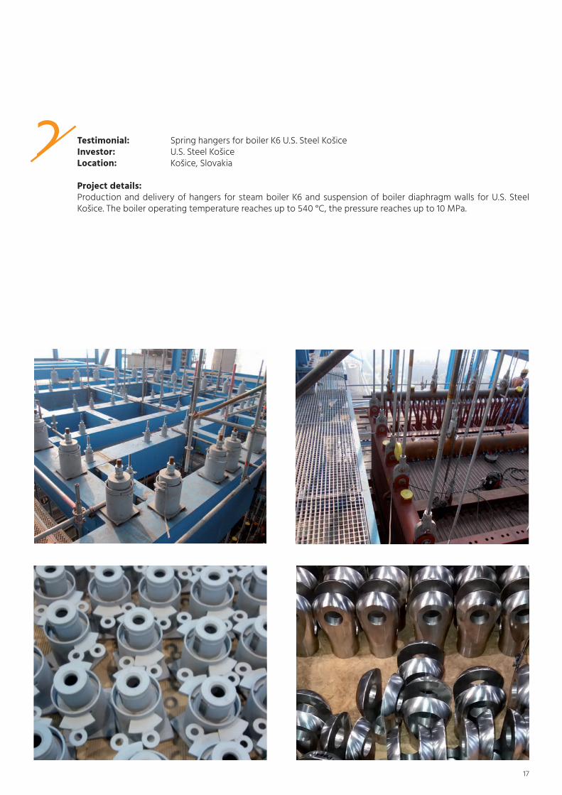
2 Testimonial: Spring hangers for boiler K6 U.S. Steel Košice Investor: U.S. Steel KošiceLocation: Košice, Slovakia
Project details: production and delivery of hangers for steam boiler K6 and suspension of boiler diaphragm walls for U.S. Steel Košice. The boiler operating temperature reaches up to 540 °C, the pressure reaches up to 10 Mpa.
17
point contact between the casing and clamp
8 mm gap
18
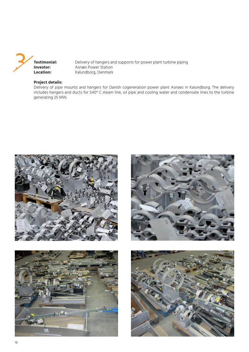
3 Testimonial: Delivery of hangers and supports for power plant turbine pipingInvestor: Asnæs power StationLocation: Kalundborg, Denmark
Project details: Delivery of pipe mounts and hangers for Danish cogeneration power plant Asnaes in Kalundborg. The delivery includes hangers and ducts for 540° C steam line, oil pipe and cooling water and condensate lines to the turbine generating 25 MW.

4 Testimonial: Delivery of pipe supports and hangers at Muara TawarInvestor: Muara Tawar power plantLocation: Bekasi, Indonesia
Project details: production and delivery of supoorts and hangers for turbine room of the Muara Tawar power plant in Indonesia.
19

20
5 Testimonial: pipe supports and hangersInvestor: South Refineries Company, Republic of Iraq, BasrahLocation: Basrah, Iraq
Project details: Production and delivery and spring hangers and supports for isomerization unit lines at an Iraqi oil refinery in Basrah, using our own production documents.

6 Testimonial: production and delivery of pipe supports for turbine roomInvestor: Etihad Food Industries Co. Ltd.Location: Iraq
Project details: production and delivery of pipe mounts for turbine room at the manufacturing company Etihad Food Industries Co. Ltd. In Iraq was split into two stages. The total deliverables included almost a tonne of supports and pipe hangers. In spite of the initial issues with design conceptions of certain steam junctions, our brilliant team of engineering experts and professional attitude of our customer still helped to proceed with immediate production launch and dispatch of the first stage batch within 3 weeks only.
21

7 Testimonial: production and supply of pipe supports and hangersInvestor: Mondi SCp Location: Mondi SCP, Ružomberok/ Slovakia
Project details: 60 ton of pipe supports and hangers for the largest investment project in the history of Mondi SCP, Ružomberok. The investment project ECO Plus includes the construction of a new paper machine PS19. Moravia Systems produ-ced pipeline supports in the dimensions from DN 15 to DN 900 for the most operational technological units of the new paper machine.
22

8 Testimonial: production and delivery of steam mesh screen Customer: Doosan Skoda power Location: Lansing power plant, Michigan/ USA
Project details: Steam mesh screen manufactured on the basis of our design and technical documentation.
23

notes
24


02/2
020
– R3
-250
Moravia systems a.s.
engineering:+420 517 070 571
Manufacturing:Průmyslová 1760, 696 42 Vracov
www.moraviasystems.cz