Production of Hydrogen For Clean and Renewable Sources of ... · Production of Hydrogen for Clean...
18
Production of Hydrogen for Clean and Renewable Source of Energy for Fuel Cell Vehicles Xunming Deng (PI), Martin Abraham, Maria Coleman, Robert Collins, Alvin Compaan, Dean Giolando, A. H. Jayatissa, Thomas Stuart, Mark Vonderembse, and William B Ingler Jr. University of Toledo Felix Castellano, Bowling Green State University 6/11/2008 Project ID # PDP 24 This presentation does not contain any proprietary, confidential, or otherwise restricted information
Transcript of Production of Hydrogen For Clean and Renewable Sources of ... · Production of Hydrogen for Clean...
Production of Hydrogen for Clean and Renewable Source of
Energy for Fuel Cell Vehicles Xunming Deng (PI), Martin Abraham, Maria Coleman,
Robert Collins, Alvin Compaan, Dean Giolando, A. H. Jayatissa, Thomas Stuart, Mark Vonderembse, and William B Ingler Jr.
University of Toledo
Felix Castellano, Bowling Green State University6/11/2008
Project ID #PDP 24
This presentation does not contain any proprietary, confidential, or otherwise restricted information
2
Overview
• Project start date: May 1, 2005• Project end date: Jan 31, 2008• Percent complete: 100%
• DOE MYPP Objective for PEC– Develop advanced renewable PEC hydrogen
generation technologies. – By 2018, verify the feasibility of these
technologies to be competitive in the long term.• Technical Targets:
– 2013: STH Eff > 8%; Durability >1,000 hours; – 2018: STH Eff > 10%; Durability >5,000 hours;
• PEC Hydrogen Generation Barriers -- MYPP 3.1.4– Y. Materials Efficiency– Z. Materials Durability– AA. PEC Device and System Auxiliary Material– AC. Device Configuration Designs– AD. Systems Design and Evaluation
• Funding for FY08: $0 Total project funding
– DOE share: $992,000– UT share: $337,551 (Revised)
• Funding received in FY05: $992,000• Funding received in FY06: $0• Funding received in FY07: $0• Funding for FY08: $0 ($992,000 Spent)
Budget
• Bowling Green State University• Midwest Optoelectronics, LLC• Xunlight Corporation
Partners
Timeline Barriers
3
Objectives
• To expand a research program directed to the development of clean and renewable domestic methods of producing hydrogen. This program will provide industry with ways to produce hydrogen in an environmentally sound manner to support the use of fuel cells in vehicles and at stationary locations.

4
Approach• Task 1: Design and analysis of DC voltage regulation system for direct PV-to-
electrolyzer power feed [100% Complete]– Design strategy for integrating a solar array with a pressurized electrolyzer (or an integrated electrolyzer
plus compressor), including pressurized hydrogen storage.– Analysis of the DC voltage regulation system required for direct PV-to-electrolyzer power feed
• Task 2: Development of substrate-type PEC cells [100% Complete]– Development of improved encapsulation materials and process – Optimization of grid configuration and installation process – Investigation of effect of various cell dimensions in the oxidation and reduction compartments – Design of improved membrane holder to prevent hydrogen and oxygen from intermixing, and – Study of various electrolyte inlet and gas/electrolyte outlet configurations
• Task 3: Development of advanced materials for immersion-type PEC cells [100% Complete]
– Deposition of a transparent, conducting and corrosion resistant coating for PEC photoelectrode. – Deposition of photoactive semiconductor as the top component cell absorber layer in a multi-junction PEC
photoelectrode– Characterization and modeling of PEC materials and photoelectrodes
• Task 4: Hydrogen production through conversion of biomass-derived wastes [100% Complete]
– Identify the products of fermentation– Catalytic reforming– Direct conversion of biomass derived resources to hydrogen
• Low temperature (< 300°C)• Pressurized, aqueous phase• Evaluate: Feedstock opportunities; Reaction conditions; Catalyst stability

5
Task 1: Design and analysis of DC voltage regulation system for direct PV-to-electrolyzer
power feed• Design strategy for
integrating a solar array with a pressurized electrolyzer (or an integrated electrolyzer plus compressor), including pressurized hydrogen storage.
• Analysis of the DC voltage regulation system required for direct PV-to-electrolyzer power feed.
Nexa®-Zahn Laboratory Test Setup
6
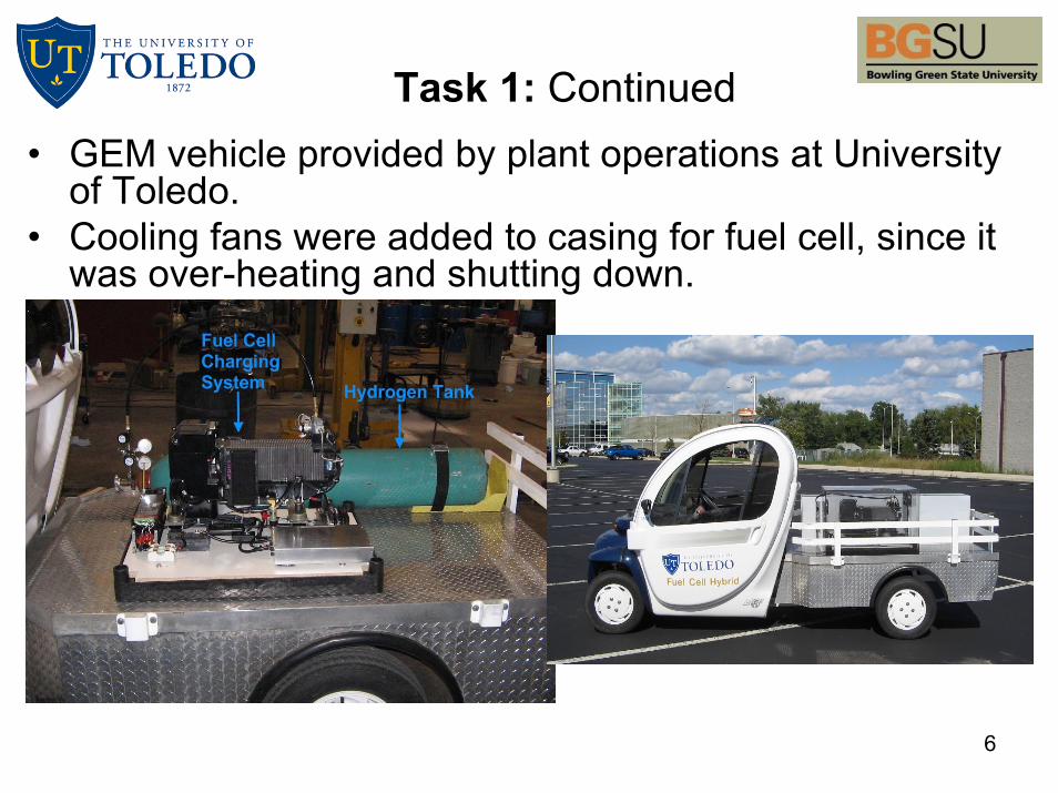
Task 1: Continued• GEM vehicle provided by plant operations at University
of Toledo. • Cooling fans were added to casing for fuel cell, since it
was over-heating and shutting down.
7
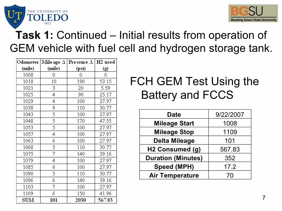
FCH GEM Test Using the Battery and FCCS
Date 9/22/2007 Mileage Start 1008 Mileage Stop 1109 Delta Mileage 101
H2 Consumed (g) 567.83 Duration (Minutes) 352
Speed (MPH) 17.2 Air Temperature 70
Task 1: Continued – Initial results from operation of GEM vehicle with fuel cell and hydrogen storage tank.
8
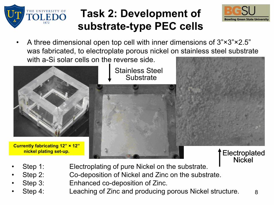
Task 2: Development of substrate-type PEC cells
• A three dimensional open top cell with inner dimensions of 3”×3”×2.5” was fabricated, to electroplate porous nickel on stainless steel substrate with a-Si solar cells on the reverse side.
Stainless Steel Substrate
Electroplated Nickel
Electroplated Nickel
• Step 1: Electroplating of pure Nickel on the substrate.• Step 2: Co-deposition of Nickel and Zinc on the substrate.• Step 3: Enhanced co-deposition of Zinc.• Step 4: Leaching of Zinc and producing porous Nickel structure.
Currently fabricating 12” × 12”nickel plating set-up.

9
Task 2: Development of substrate-type PEC cells
• Left – Pulsed DC-Power Supply with electroplating bath for electrodeposition of porous nickel.
• Right – 20× magnification of porous nickel substrate.
100 kHz
20 kHz
100 kHz – Cross-section
10
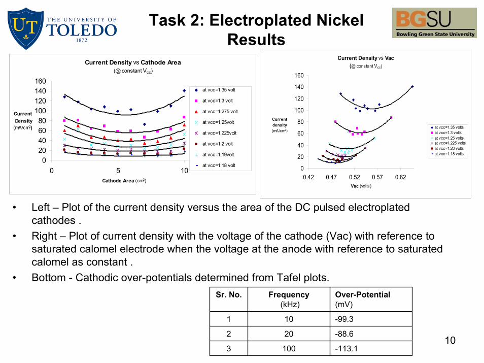
• Left – Plot of the current density versus the area of the DC pulsed electroplated cathodes .
• Right – Plot of current density with the voltage of the cathode (Vac) with reference to saturated calomel electrode when the voltage at the anode with reference to saturated calomel as constant .
• Bottom - Cathodic over-potentials determined from Tafel plots.
Current Density vs Cathode Area(@ constant Vcc)
020406080
100120140160
0 5 10Cathode Area (cm2)
Current Density(mA/cm2)
at vcc=1.35 volt
at vcc=1.3 volt
at vcc=1.275 volt
at vcc=1.25volt
at vcc=1.225volt
at vcc=1.2 volt
at vcc=1.19volt
at vcc=1.18 volt
Current Density vs Vac(@ constant Vcc)
0
20
40
60
80
100
120
140
160
0.42 0.47 0.52 0.57 0.62Vac (volts)
Current density(mA/cm2)
at vcc=1.35 voltsat vcc=1.3 voltsat vcc=1.25 voltsat vcc=1.225 voltsat vcc=1.20 voltsat vcc=1.18 volts
Sr. No. Frequency(kHz)
Over-Potential(mV)
1 10 -99.3
2 20 -88.6
3 100 -113.1
Task 2: Electroplated Nickel Results
11
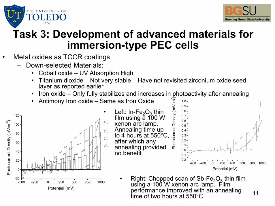
Task 3: Development of advanced materials for immersion-type PEC cells
• Metal oxides as TCCR coatings – Down-selected Materials:
• Cobalt oxide – UV Absorption High• Titanium dioxide – Not very stable – Have not revisited zirconium oxide seed
layer as reported earlier• Iron oxide – Only fully stabilizes and increases in photoactivity after annealing• Antimony Iron oxide – Same as Iron Oxide
-500 -250 0 250 500 750 1000-20
0
20
40
60
80
100
120
Pho
tocu
rrent
Den
sity
(μA
/cm
2 )
Potential (mV)
0 h
2 h
6 h
4 h
-400 -200 0 200 400 600 800 1000-0.2-0.10.00.10.20.30.40.50.60.70.80.91.0
Phot
ocur
rent
Den
sity
(mA
/cm
2 )Potential (mV)
• Left: In-Fe2O3 thin film using a 100 W xenon arc lamp. Annealing time up to 4 hours at 550°C, after which any annealing provided no benefit
• Right: Chopped scan of Sb-Fe2O3 thin film using a 100 W xenon arc lamp. Film performance improved with an annealing time of two hours at 550°C.

12
• Metal oxides as Photoactive Semiconductor (PAS)– Indium Iron Oxide
– Top Left: Photocurrent of all samples that were made at the best conditions of: 228°C, 30 W of indium, 100 W of iron oxide, 2 hour sputter deposition period.
– Top Right: Samples made at best conditions of 228°C with 30 W of indium and 100 W of iron oxide. The graph shows the relationship between photocurrent and film thickness.
– Bottom Right: Optical Absorption measurements from UV/vis.
-20
0
20
40
60
80
100
120
-600 -400 -200 0 200 400 600 800 1000 1200
Potential (mV)
Phot
ocur
rent
Den
sity
[µA/
cm²]
ST 671ST 686ST 691
-60
-40
-20
0
20
40
60
80
100
120
140
-600 -400 -200 0 200 400 600 800 1000 1200
Potential (mV)Ph
otoc
urre
nt [
µA/c
m²]
ST671ST687 (Dep Time: 1.5 hours)ST686 (Dep Time: 2.0 hours)ST688 (Dep Time: 2.5 hours)
0
20
40
60
80
100
120
0 500 1000 1500 2000 2500
Wavelength (nm)
Perc
ent T
rans
mitt
ance
• Film thickness = 1150 nm
Task 3: Continued

13
0
20
40
60
80
100
250 350 450 550 650 750 850 950Wavelength (nm)
%T
Cuvette + Electrolyte
Sample
Setup B
(a)
(b)
(c)
(d)
0
10
20
30
40
50
60
70
80
90
100
250 350 450 550 650 750 850 950
wavelength (nm)
%T
(b)(c)(d)(e)(f)
(a)
Cuvette + air
Sample
Setup A
• Metal oxides as TCCR coatings– Tin Oxide (F-Doped)
• SnO2:F thin films were deposited on stainless steel and on Tec 15 (commercially available highly conductive SnO2:F) at a low temperature between 200°C and 250°C by spray pyrolysis.
• When connected as an anode in the electrolysis cell, the low temp SnO2:F thin films lasted for up to three months while maintaining a current density of 0.008 A/cm2, using 3.5 V for coated Tec15 and around 2.2 V for those deposited on stainless steel.
• Samples coated with an undoped tin oxide thin film failed to last for even a few hours under the same conditions in a highly concentrated KOH electrolyte solution.
– Tin Oxide (Sb-Doped)• Antimony doped tin oxide (SnO2:Sb) thin films were deposited on Tec 15, where the solution was
prepared from a solution of tin tetrachloride dissolved in a mixture of water and ethanol. • The resulting films, which exhibited a sheet resistance of circa 500 Ω, were connected to the
electrolysis cell where they lasted for barely a few hours under the same conditions stated previously for the stability tests with SnO2:F.
(a) glass, (b), (c), (d) glass/TCCR, (e) TEC15/TCCR, (f) TEC15
14
• Production of hydrogen from biomass for its use in fuel cells for transportation and stationary applications
– Choice of appropriate method for biomass conversion to hydrogen
– Demonstrate the feasibility of proposed process
– Optimization of the process parameters in order to enhance the hydrogen productivity
Task 4: Hydrogen production through conversion of
biomass-derived wastes

15
The performance of the Pt-Co catalyst supported on activated carbon when exposed to different impurities
Reaction:
C2H5OH + 3H2O 6 H2 + 2 CO2
Task 4: Hydrogen production through conversion of
biomass-derived wastes
0
2
4
6
8
10
12
14
16
18
20
0 10 20 30 40 50 60 70 80 90 100
Time, h
% H
2 Yi
eld
13 ppm P10 ppm S
16
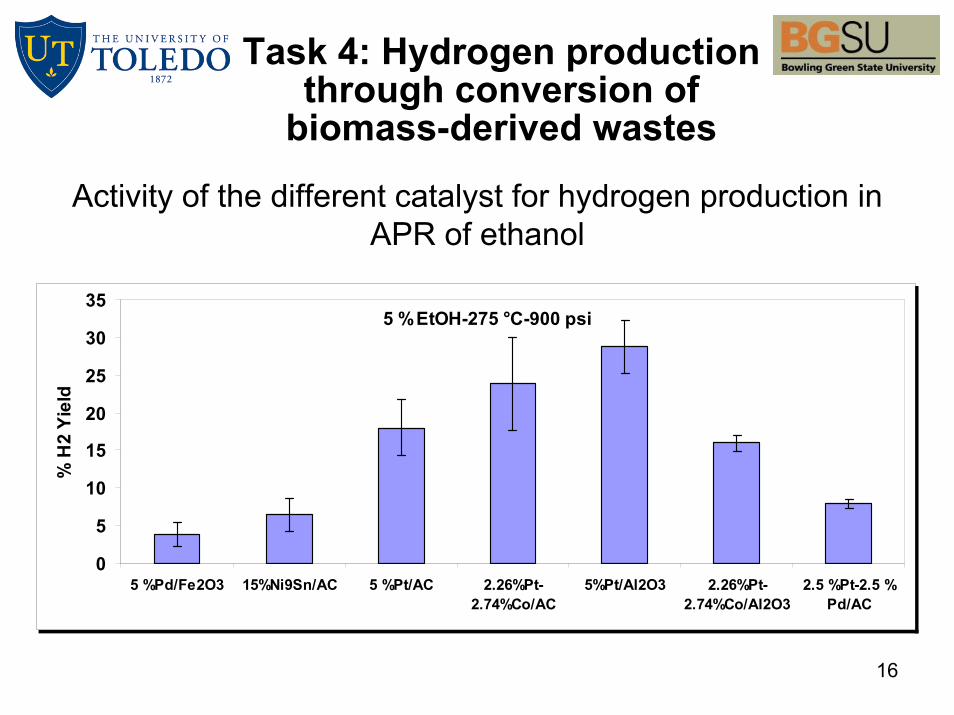
Activity of the different catalyst for hydrogen production in APR of ethanol
Task 4: Hydrogen production through conversion of
biomass-derived wastes
5 %EtOH-275 °C-900 psi
0
5
10
15
20
25
30
35
5 %Pd/Fe2O3 15%Ni9Sn/AC 5 %Pt/AC 2.26%Pt-2.74%Co/AC
5%Pt/Al2O3 2.26%Pt-2.74%Co/Al2O3
2.5 %Pt-2.5 %Pd/AC
% H
2 Yi
eld
17
Future Work
• Task 2: Production of final module design with electroplated nickel on back of stainless steel with triple junction a-Si on front.
• Task 3: Continued study into optimization of present oxide materials.
• Task 3: Deposition of oxides under higher power and with metallic targets to improve stability and oxide structure.

18
Project Summary
• Relevance: Addresses DOE program objectives, specifically high-efficiency and low-cost production of hydrogen using photoelectrochemical methods.
• Approach: An immersion–type photoelectrochemical cells where the photoelectrode is immersed in electrolyte and a substrate-type photoelectrochemical cell where the photoelectrode is not in direct contact with electrolyte.
• Technical Accomplishments and Progress: Demonstrated a PV-electrolysis system that has separate PV system and electrolysis unit and the hydrogen generated is to be used to power a fuel cell based vehicle in the near future.
• Technology Transfer/Collaborations: Active collaboration with MWOE and Xunlight towards commercialization of research done at UT
• Proposed Future Research: Further develop TCCR coatings for immersion and substrate-type cells.