Production of elec- tric cars-electric buggy - e-motion.si · Technical High School Pula, along...
32
0 With the support of the Lifelong Learning Programme of the European Union. This project has been funded with support from the European Commission Production of elec- tric cars-electric buggy
Transcript of Production of elec- tric cars-electric buggy - e-motion.si · Technical High School Pula, along...

0 With the support of the Lifelong Learning Programme of the European Union. This project has been funded with support from the European Commission
Production of elec-
tric cars-electric
buggy

1 With the support of the Lifelong Learning Programme of the European Union. This project has been funded with support from the European Commission
Chapter 1 Introduction ........................................................................... 2
Chapter 2 Elements of electric vehicle .................................................... 3
Chapter 3 Selection of vehicle for remake into electric ............................... 8
Chapter 4 Selection of electric engine, controller and battery............... 9
Chapter 5 List of tools and materials required for processing .................. 20
Chapter 6 Installation of electric engine and controller ........................... 21
Chapter 7 Installing the battery ............................................................. 22
Chapter 8 Setting up the photovoltaic (PV) panel .................................. 24
Chapter 9 Wiring ..................................................................................... 25
Chapter 10 The program for adjusting the engine and controller settings 27
Chapter 11 Testing of the vehicle.......................................................... 29
Chapter 12 Conclusion ........................................................................... 30
Chapter 13 References and sources ...................................................... 31

2 With the support of the Lifelong Learning Programme of the European Union. This project has been funded with support from the European Commission
Chapter 1 Introduction
Technical High School Pula, along with its partners TSC Nova Gorica, Slovenia, ITIS
Cardano Pavia, Italy and Le Vele Pavia, Italy from the educational sector during the
years of 2012 and 2013 was involved in the project MESA (Mechatronics in energy
saving applications) financed by the European Union through the funds for lifelong edu-
cation Leonardo da Vinci.
The main objective of the project is to spread knowledge and skills in the field of mecha-
tronics for the promotion and upgrade of specialized skills required in today's job mar-
ket.
The project objectives are:
• Improve the capability of school education in the field of science and technology
• improve the creativity and professionalism of teachers and students
• Recognizing and equalizing the European level of knowledge and competence
• The application of mechatronics for a more efficient use of solar energy
The objectives of the project at the Technical School Pula are achieved by remaking a
buggy vehicle into an electric buggy vehicle.
This manual will enable other schools and individuals to theoretical knowledge and
practical experience in the remake of vehicles in order to facilitate the remake of other
vehicles that will be used for didactic purposes.
The project enabled advanced exercises for teachers and students in the field of new
technologies, the comparison of educational curricula in secondary schools in three
countries (Slovenia, Italy and Croatia) and their equalization.
Students achieved theoretical and practical knowledge and skills which will help them
get a job more easily on the job market.
The project retains contact with the industrial progress and achievements. Meetings,
seminars and workshops were held to disseminate the acquired knowledge.

3 With the support of the Lifelong Learning Programme of the European Union. This project has been funded with support from the European Commission
The usage of solar energy was realized by installing photovoltaic panels on the roof of
the buggy. The panels complement the batteries while driving or while still, as long as
there is sunlight.
Chapter 2 Elements of electric vehicle
The electric vehicle (EV- electric vehicle) is a vehicle powered by an electrical
engine {1}
• Plug-in electric vehicle (PEV) is a term that covers all types of electric vehicles rechar-
ged from the elecrtical network, battery powered electric vehicles (BEV battery-powered
electric vehicles). PEV is an abbreviation that covers vehicles that use electricity from
the mains to recharge the battery.
Electric vehicles include electric cars, electric trains, electric airplanes, electric boats,
electric motorbikes and scooters and electric bicycles.
Depending on the propulsion, there are three types of electrical vehicles
BEV (battery- powered electric vehicles) electric vehicles powered by batteries
With this type of vehicle electrical power is stored in batteries and there is no other
energy reservoir. When the batteries are depleted the vehicle stops up until they are re-
filled by connecting them to the mains.
BEV vehicles have the following characteristics:
• they have only one electrical drive engine
• they have the largest installed capacity of the battery to ensure a maximum dri-
ving range
• charging time is the longest of any other electric vehicle
• vehicles without pollution (zero-emission)

4 With the support of the Lifelong Learning Programme of the European Union. This project has been funded with support from the European Commission
• primary fuel is electrical power
EREV (An Extended Range Electric Vehicle) electric vehicles with increased
range
This type of vehicle has batteries, an electric motor and an internal combustion
engine which serves to drive the generator, which complements the batteries when the
battery level drops below minimum. The fuel for the propulsion of the internal combusti-
on engine is petrol, diesel or LPG. The propulsion engine of the vehicle is always an
electromotor.
This group includes electric vehicles with fuel cells (A fuel-cell electric car) which charge
the battery directly by fuel cells.
EREV vehicles have the following characteristics:
• unlimited range by driving in an economical electric drive
• vehicles of low emission pollution
• primary fuel is electricity
PHVE (a Plug-in Hybrid Vehicle) electric hybrid vehicles
PHVE vehicles have dual propulsion: an internal combustion engine and an electric mo-
tor. The batteries have a larger capacity than the regular hybrid vehicles so that the dri-
ving range to stored energy batteries is about 30 kilometers before the drive motor is
switched to the internal combustion engine.
PHVE vegicles have the following characteristics:
• have a dual-drive motor with an internal combustion engine and an electric motor
• the range of driving on electric propulsion is approximately 30 kilometers

5 With the support of the Lifelong Learning Programme of the European Union. This project has been funded with support from the European Commission
Advantages of electric vehicles
• electricity is widely available and includes the production of renewable energy
sources (wind, sun, water, etc.)
• electric propulsion is considered to be cleaner than the propulsion with internal
combustion engines by 50% {2} although during the production of electricity CO2 emis-
sions into the environment occur
• it is easier to reduce CO2 emissions by installing filters in power stations than in
millions of vehicles with internal combustion engines
• electric vehicles produce less noise - noise pollution compared to vehicles with
internal combustion engines
• electric motors do not require oxygen as opposed to internal combustion engines
which can be used particularly in submarines or space vehicles and fire department ve-
hicles{3}
• electric motors are mechanically very simple
• electric motors reach a usefulness of 90% over the entire range of speeds, easy
to manage speed of rotation. Electric vehicles use regenerative braking, which means
that the braking energy in electric drive that works in generating mode is converted into
electrical energy and complements the batteries thus reducing the overall consumption.
Cost effectiveness of regenerative braking is particularly emphasized in city driving
• with controllers electric motors can be operated at full speed range while mainta-
ining high torque which allows operation without gear and transmission as opposed to
internal combustion engines
• up to five times more economical driving compared to vehicles with internal com-
bustion engines, such as electric car Chevrolet Volt power 111kw/150KS that spends
0.02 cents per kilometer {4}

6 With the support of the Lifelong Learning Programme of the European Union. This project has been funded with support from the European Commission
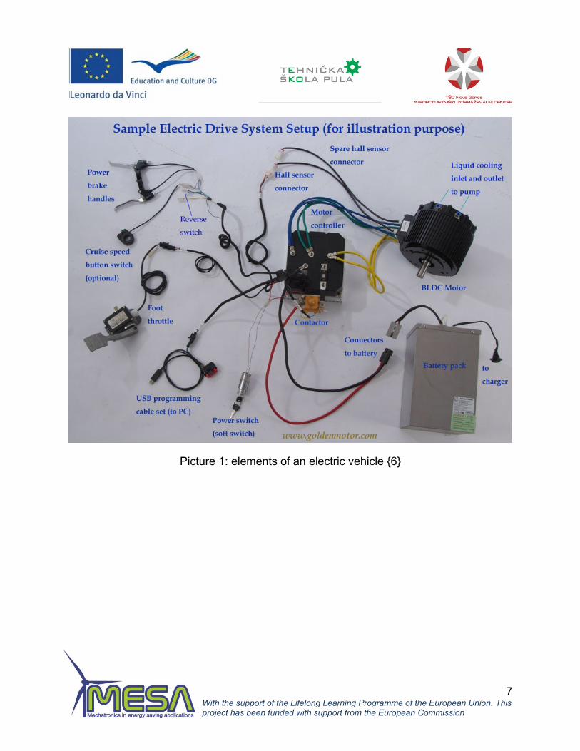
Requirements of the remake into electric vehicle are the following:
• construction of the vehicle
• electrical engine
• controller
• battery pack
• charger
• gas pedal
• contactor
• electric lock
• Hall sensor
• cable for programming controllers
• gear or adaptation to connect the electric engine to the transmission of the vehic-
le
• electrical enclosures and wiring
Picture 1: elements of an electric vehicle {5}
7 With the support of the Lifelong Learning Programme of the European Union. This project has been funded with support from the European Commission
Picture 1: elements of an electric vehicle {6}

8 With the support of the Lifelong Learning Programme of the European Union. This project has been funded with support from the European Commission
Chapter 3 Selection of vehicle for re-make into electric
From the outside you can not recognioze whether a vehicle is electric or gasoline.
Electric vehicles are generally obtained by remaking the original vehicles into electric
vehicles.
When selecting a vehicle that will be processed into an electric one we had in mind our
cash budget, and the request that the electric vehicle after the performance can be used
as a didactic tool for performing exercises.
You should also consider whether there is a workshop - space for accommodation and
work. For smaller vehicles the minimum area workshop should be 6x5 meters. The
workshop must have access to a welding device, a drill and a sander.
When choosing the model for the remake the budget, the vehicle weight which is asso-
ciated with the size of the cordless pack should be taken into consideration. Lighter mo-
dels are usualy chosen,
We had the opportunity to buy and remake a small serial petrol car, go kart or cross
cart.
We decided for the cross cart because of the attractiveness of performance and the
open design suitable for the installation of the engine and photovoltaic panels on the
roof.
Picture 3: Cross cart Picture 4: Go kart Picture 5: Daewoo Tico

9 With the support of the Lifelong Learning Programme of the European Union. This project has been funded with support from the European Commission
Chapter 4 Selection of electric engine, controller and battery
In the past, because of the speed control the electric cars were remodeled with DC mo-
tors with brushes.
Nowadays, electric cars are built with two types of motors: AC induction motor with
asynchronous cage rotor (AC) or direct current motor with permanent brushless mag-
nets. (BLDC brushless discrete current)
Both types of engines are installed into the car driven by electronic converters - control-
ler (inverter).
BLDC engines
In BLDC engines the rotor is constructed of two or more permanent magnets. On the
stator there are windings (usually three). By bringing the AC voltage on the windings it
creates a rotating magnetic field that rotates the frequency ratio of applied voltages. The
rotor magnets attracted by the stator magnetic field rotate synchronously with it. BLDC
engines have the structure and working principle similar to AC synchronous engines,
save synchronous engines usually have the electromotor on the rotor. To work properly
BLDC engines must necessarily have a controller that outputs an alternate three phase
voltage - trapezoidal. Changing speeds is due to changes in voltage frequency at the
output of the controller. Without a controller the BLDC engine is unusable.
Alternating asynchronous cage engines
This type of engine was invented by Nikola Tesla, born in Smiljan (Croatia). Similar to
the BLDC engine, there are three phase windings on the stator to which a three-phase
voltage is conducted. Currents start flowing, creating a rotating magnetic field. The rotor
of the asynchronous cage engine is made by casting ferromagnetic materials. The slots
in the form of a cage are cast with aluminum. This cage replaces the windings on the

10 With the support of the Lifelong Learning Programme of the European Union. This project has been funded with support from the European Commission
rotor and thus simplifies and cheapens the engines. On the cage located in the chan-
ging magnetic field voltages are induced which drive electricity generating magnetic
field of the rotor, which seeks to track the stator rotating magnetic field, but is always a
little late. This delay of order a few percentages is expressed by a measure called slip-
page.
The three-phase asynchronous engine is the most commonly used engine because of
its simple structure and it can work directly on a three-phase network without any
extras. That way it has an approximately constant speed. For the use in electric cars
and battery power, there must also be a contoroller-inverter that converts the direct cur-
rent from the battery into alternating three-phase current which is brought onto the en-
gine windings.
Advantages and disadvantages
Asynchronous cage engines are simpler and therefore cheaper and more reliable
BLDC engines are to be fitted with position sensors (Hall sensor) while induction engi-
nes should only have a speed sensor. Both engines must have controllers - inverters,
but the program for managing the asynchronous engine is more complex and it is more
difficult to manage a asynchronous motor.
All hybrid cars have a built-BLDC engine.
The main difference is that the BLDC rotors generate less heat and it is easier to drain
the heat from the engine. That way they have a couple of percentage points higher
utility. The usefulness of asynchronous engines is about 85%. The advantage of BLDC
engines is that with a large constant utility they work throughout the speed range while
asynchronous engines have a large drop in utility for smaller speeds.
BLDC engines have powerful permanent magnets which are difficult to handle during
the engine performance.
BLDC engines have permanent magnets and can not reduce the magnetic flux density,
which can be performed with asynchronous engines and thereby reduce losses in the
region of small mechanical loads when there is no need for mechanical torque.
BLDC engines dominate the field of hybrid and PEHV vehicles, while asynchronous ca-
ge engines dominate the field of pure electric vehicles with high performances.

11 With the support of the Lifelong Learning Programme of the European Union. This project has been funded with support from the European Commission
Taking into account the above and the experiences of colleagues who had the same
engine installed in a DAEWOO TICO, we decided to go for the BLDC engine of the
company GOLDEN MOTOR which specialized in the equipment for remaking electric
vehicles.
The engine has an HPM-5000B label
Power : 3-8 KW
Voltage: 72 V
Utiltiy : 91%
Speed: 2000-6000 rounds per minute
Mass: 11 kg
Picture 6: BLDC Motor Golden Motor

12 With the support of the Lifelong Learning Programme of the European Union. This project has been funded with support from the European Commission
Picture 7: Schematic
re- presentation of the BLDC
en- gine {7}
Picture 7: Cross-section of the AC asynchronous cage engine

13 With the support of the Lifelong Learning Programme of the European Union. This project has been funded with support from the European Commission
Controllers
BLDC controllers
Controllers are electronic devices that bring power to the electric motors. In BLDC engi-
nes they take the direct current from the battery using a bridge with six powerful MOS-
FET transistors and form a three-phase trapezoidal AC voltage which is then applied to
the motor windings. By changing the frequency of the voltage the motor speed is chan-
ged. By means of a microcontroller as the heart of the controller we read the signal from
the pedals obtained by using a potentiometer, and the signals of the position of the rotor
obtained by means of Hall probes.
The controller gives the frequency and power depending on the obtained signals.
The controllers enable regenerative braking, which means that braking takes place by
using the engine that goes into generator mode and the resulting current complements
the batteries. This way a higher efficiency and a greater vehicle range are achieved
Picture 9: Schematic representation of the BLDC controllers

14 With the support of the Lifelong Learning Programme of the European Union. This project has been funded with support from the European Commission
Controller for asynchronous cage engines
Asynchronous cage engines are harder to maneuver than BLDC engines ie the mana-
gement program is much more complex. At the outlet the MOSFET generates a three-
phase voltage that must be a sinusoid. There is no Hall sensor positioned. Instead, the
position of the rotor is determined by measuring the induced voltage on the stator.
Picture 10: Schematic representation
of the induction motor controllers
According to the selected BLDC engine of the company GOLDEN MOTOR in the kit we
bought a controller HPC300H 72V 300A. Controllers of the company Golden Motors of
HPC Series are designed for strong, reliable BLDC engines. The housing is completely
waterproof with an IP66 protection.
By using specialized software using a computer via the USB port it is possible to adjust
the parameters of the controller.
Controller features:
Intended for BLDC engines
Low noise engine with stable torque
Maximum utiltiy > 98%
IP 66 protection
23-pin waterproof connector
Regenerative braking

15 With the support of the Lifelong Learning Programme of the European Union. This project has been funded with support from the European Commission
Regulation of rotation speed
Overheat protection for the engine and the controller
Programmable via PC and USB ports
Programming of the maximum temperature of engine
DSP (digital signal processor) management
Optional CAN interface
Possible work with two controllers in a synchronous operation
Protection of vehicle from sliding when parking uphill
Picture 11: BLDC controller
Golden motor
Batteries
Nowadays, electric cars mainly use two types of batteries:
Dry-lead (SLA sealed lead acid) Lithium-ion (LiFePo4)
Dry-lead batteries have two lead plates as start car batteries, save between the plates
there is no liquid acid, but gel acid. There are two kinds of dry-lead batteries- gel type
and AGM (absorbent glass mat).
Dry-lead batteries have a wide range of applications to store electricity. They are used
in photovoltaic systems, electric children vehicles, electric wheelchairs, systems to pro-
tect facilities, uninterrupted power systems (UPS) and the like.

16 With the support of the Lifelong Learning Programme of the European Union. This project has been funded with support from the European Commission
Lithium ion batteries are newer batteries which are particularly applied in consumable
electronics (cell phones) and electric cars due to their good characteristics.
This type of battery has at least one electrode derived from lithium.
There are different types of lithium ion batteries, however the one used in cars is lithium
iron (LiFePO4).
Lithium iron batteries have a high density of energy storage. On the other hand, they do
not have the so-called memory effect (reduction in capacity due to insufficient battery
charge and discharge cycles). They are much lighter compared to lead acid batteries
but they have the same voltage which is why they are installed in electric vehicles such
as golf electric vehicles, without any modifications to the vehicle itself.
Lithium ion batteries can be dangerous in certain conditions because their electrolyte is
flammable under pressure. Special safety precautions are required when installing and
using.
The comparison between dry lead and lithium ion batteries
Dry lead LiFePo4
Output current 0,5 * C (C=capacity) 3*C short term (5-8)*C
Durability (Number of cy-
cles)
400 2000
Environmental pollution Enviromental pollution, re-
cycling and saving essential
No pollution
Volume 1 65% lead
Mass 1 33% lead
Price per Wh 1 5* lead
Price per Wh and number
of cycles
1 1

17 With the support of the Lifelong Learning Programme of the European Union. This project has been funded with support from the European Commission
Although lithium iron batteries are built in modern electric cars built due to their lower
mass, volume and higher discharge, dry-lead batteries are installed in projects that fo-
cus on low cost per Wh.
Since our electric vehicle will be used for didactic purposes, as well as having a lower
budget, we chose cheaper dry-lead batteries with weaker characteristics than lithium
iron.
We have chosen the motor voltage of 72 V, according to the engine’s power of 5 kW.
The batteries will be connected in series so it is necessary to incorporate 6 dry-lead bat-
teries. As for the battery capacity, we chose 75 Ah which is enough for approximately 2
hours of driving a buggy. The stored battery energy is W = U * C * = 72V 75Ah = 5,400
Wh.
The engine power is 5 kW, and driving at 50% power of the rated power of 2.5 kW =
2500 W, the driving duration is t= W/P=5400/2500=2,16 hours. The total mass of the
battery is 6 * 21 kg = 126 kg
Picture 12 : The chosen dry-lead battery Picture 13: LiFePO4 battery
The chargers

18 With the support of the Lifelong Learning Programme of the European Union. This project has been funded with support from the European Commission
There are several ways if charging a battery pack, one of them being six batteries con-nected in a series. It is possible to charge all six batteries with one charger for 72 V. The flaw of this method is that the batteries will be charged differently if there is a certain asymmetry in the batteries, meaning some batteries will get charged less and some more, as well as spend more. Since the difference grows larger in time, individual max-imum charging has to be done occasionally to balance the batteries.We chose the method where each battery has its own charger and work independently. The chargers are smart electronic from the CTEK company from Sweden.
Characteristics of the charger:
Fully automatic charger with six degrees
Designed for charging lead acid batteries (WET, MF, GEL and AGM) from 14 Ah
to 225 Ah
Pulse charging for maintenance purposes extends the life of the battery.
Can be used as a power source
Recharges even fully discharged batteries. Pulse charging reduces the amount
of sulphate oxide in the battery
Four modes of charging: 14.4 V, 14.7 V, 13.6 V / source power supply ; 16V / for
discharged batteries
Low discharge current, insensitive to voltage instability (for a voltage of 170-260
V)
High efficiency: 85%
The charger can be connected to the battery for months - ideal for seasonal ve-
hicles (motorcycles, scooters, vessels, etc.)

19 With the support of the Lifelong Learning Programme of the European Union. This project has been funded with support from the European Commission
Picture 14: The chosen charger
BMS (Battery Management System) – system that manages
battery charging and discharging
BMS monitors the current state of the battery through the following metric sizes:
voltage of the whole battery puck, individual cells, minimum and maximum volt-
age of the cells
temperature, medium temperature, coolant temperature
state of charge – SOC
the strength of the input and output current
BMS also allows you to monitor the battery charging during regenerative braking.
BMS particularly serves to protect the puck from:
overcharging and overdischarging
high voltage during discharging
deep discharge
too high or too low temperature
current failure detection

20 With the support of the Lifelong Learning Programme of the European Union. This project has been funded with support from the European Commission
Chapter 5 List of tools and materials re-quired for processing
In order to successfully transform a vehicle into an electric vehicle, a workshop with a
minimum size of 6x5 meters is required as well as the following tools:
•
A crane for extraction – engine in-
stallation
• An electric grinder
• An electric saw
• An electric drill
• An electric welding machine
• A set of drill bits for metal
• A set of screwdrivers
• A set of forked and ratchet
wrenches
• A universal measuring device
• Current clamps
• An oscilloscope
• Pliers
• Tweezers
• A blowtorch
• Goggles
• An anti-corrosion spray
• Pop rivets and tools
• Various screws
• Aluminium L profiles
• A measuring tape
• A caliper
• A set of markers
• Isolation tape
• A magnifier
• An auxiliary DC power source
.
During installation, we used the services of a craftsman for the production of the engine
cogwheel and the adapter for the engine installation.

21 With the support of the Lifelong Learning Programme of the European Union. This project has been funded with support from the European Commission
Chapter 6 Installation of electric engine and controller
Before installing the engine it is necessary to dismantle the existing gasoline engine. To
remove the engine an auxiliary crane is required. Our vehicle was purchased without an
engine, so we used the crane for the engine installation. We had to order a cogwheel for
the engine to be able to connect the drive shaft of the buggy with a double chain which
already had its sprocket. When installing, it is of utter importance to pay particular atten-
tion to the alignment of the cogwheel
Picture 15: Ordered cogwheels
The controller is usually mounted above the engine and is the first thing you see when
you open the hood of a car. We set it upon a perforated plate above the engine. On the
same plate we built an inverter, which serves to raise the voltage of the photovoltaic
panels, so that the chargers could be charged with the electricity generated from the
panels.

22 With the support of the Lifelong Learning Programme of the European Union. This project has been funded with support from the European Commission
Picture 16: The installed motor
Picture 17: The installed controller and inverter
Chapter 7 Installing the battery
The batteries must be mounted symmetrically and as low as possible in order to pre-
serve the stability of the vehicle. We set up the batteries with a bracket made of L pro-
files. The batteries were placed in plastic boxes designed specifically for their installa-
tion in vessels because the lids protect against splashing water.
The total mass of the batteries installed in the buggy is 6x21 kg = 122 kg.
The batteries are connected in series and a charger is connected parallelly to each of
them. In this way, we avoided the need for alignment.

23 With the support of the Lifelong Learning Programme of the European Union. This project has been funded with support from the European Commission
Picture 18: The batteries box

24 With the support of the Lifelong Learning Programme of the European Union. This project has been funded with support from the European Commission
Picture 19: The installed batteries
Chapter 8 Setting up the photovoltaic (PV) panel
To demonstrate the use of renewable energy sources, it is intended that the buggy’s
roof is covered with a photovoltaic panel that constantly supplements the batteries
which are normally filled by connecting them to the network.
The contribution of the photo voltage panel is relatively small because of the small roof
surface. Two panels, both of 30 W, were built onto safety bars. Furthermore, we came
up with a pull-out system for vehicle parking which adds two extra panels of the same
size.
.

25 With the support of the Lifelong Learning Programme of the European Union. This project has been funded with support from the European Commission
Picture 20: Installing a PV panel
Chapter 9 Wiring
In accordance with the scheme of the engine manufacturer and the controller, the stu-
dents used flexible conductors to wire the batteries, the motor controller, the pointers
and such. Particular attention should be paid to cross sections that connect the batteries
and the engine since the current rises up to 100 amps, so we selected a wire size of 16
mm2.
Picture 21: Shematic of wiring

26 With the support of the Lifelong Learning Programme of the European Union. This project has been funded with support from the European Commission
Slika 22: The installed contactor
Picture 23: Wiring

27 With the support of the Lifelong Learning Programme of the European Union. This project has been funded with support from the European Commission
Chapter 10 The program for adjusting the engine and controller settings
After setting up the engine and batteries it is possible to adjust the configurations of the
controller via a cable labelled PI-400. The program has an MISVC label.
Upon the first connecting, it is necessary to eliminate possible errors. The program al-
lows you to work in two modes – online and offline. The online mode includes all the
wiring connected to the controller and the motor while in offline mode the set-
tings are changed on the controller that is not wired.
You can adjust various parameters such as the number of pole pairs, the maximum
output current, maximum voltage.
The optimal parameters of the controller are obtained after a series of attempts. It is not
necessary that the user changes the parameters; you can use the default settings. Also,
there is always the option to return to the default settings.
The program also serves to control the whole system. It is possible to monitor the fol-
lowing parameters:
the amount of energy already stored in batteries (Ah)
the temperature of the controller (° C)
the temperature of the engine (° C)
battery life (Hr)
voltage (V)
current power (A)
power of the phase current (A)
vehicle speed (km / h)
engine speed (rev / min)
The program is used to set and monitor a number of other parameters related to the
controller, motor, batteries and vehicle.
.
.

28 With the support of the Lifelong Learning Programme of the European Union. This project has been funded with support from the European Commission
Picture 24: The controller USB connector
Picture 25: Program MISVC

29 With the support of the Lifelong Learning Programme of the European Union. This project has been funded with support from the European Commission
Chapter 11 Testing of the vehicle
The batteries, chargers, the electric engine and the controller were examined during the
assembling.
The electric motor was examined by raising the chassis of the buggy by using wooden
supports to keep the wheels in the air. The measured parameters of the engine were
the voltage, the current, a waveform using UNIMER, current clamps and an oscillo-
scope. At the same time, measurements were done on a computer using the MISVC
program.
Tests of individual displays (turn indicators, lights, battery charge indicator, speed indi-
cator) were studied when wiring.
Once the vehicle was completed, tests were performed out in the run. The following was
examined:
The current of the engine phase
Voltage of the engine
Battery voltage – charge state
Driving speed
Acceleration of vehicle
Battery life – driving

30 With the support of the Lifelong Learning Programme of the European Union. This project has been funded with support from the European Commission
Chapter 12 Conclusion
Thanks to the EU program Leonardo da Vinci and project partners, the following go-
als of the MESA project have been achieved at Technical School Pula. Throughout the preparations, presentations, meetings, trainings, both during the pro-
duction as well as testing stages, the students and teachers improved their knowledge
and skills in the field of electric cars and their components.
Furthermore, they have significantly improved their knowledge of the English language.
Their communication with colleagues in Slovenia and Italy made them gain experience
in working in other countries, thus making it possible to compare them.
Using PV panels raised the awareness as well as the need for the usage of renewable
energy sources.

31 With the support of the Lifelong Learning Programme of the European Union. This project has been funded with support from the European Commission
Chapter 13 References and sources
{1} http://pluginmichigan.org/pev-basics/whats-pev
{2} Chip Gribben. "Debunking the Myth of EVs and Smokestacks". 15 October 2010.
{3} http://en.wikipedia.org/wiki/Electric_vehicle#Components
{4} http://www.chevrolet.hr/dozivi-chevrolet/buduci-automobili/volt-production-
proizvodni-model.html#_SP7
{5} http:www.chromausa.comelectric-vehicle-test-solutions.php
{6} http://www.goldenmotor.com/
{7} http://www.avdweb.nl/Article_files/Solarbike/Motor-controller/4-Pole-brushless-DC-
motor-animation.jpg
{8} http://www.teslamotors.com/blog/induction-versus-dc-brushless-motors
www.xfab.com/en/technology/applications/high-voltage/bldc-motor-controller/
www.datasheetdir.com/Ready-to-use-Ac-Induction-Motor-Controller-Ic-For-Low-cost-
Variable-Speed-Applications%2bApplication-Notes