Production of biofuels by copyrolysis of biomass and waste...
37
1 Submitted, accepted and published by: Fuel Processing Technology (2014), 119, 263-271. Co-pyrolysis of biomass with waste tyres: upgrading of the liquid bio- fuel Juan D. Martínez a,b , Alberto Veses a , Ana M. Mastral a , Ramón Murillo a , Maria V. Navarro a , Neus Puy c , Anna Artigues c , Jordi Bartrolí c , Tomás García , a a Instituto de Carboquimica (ICB-CSIC), C/Miguel Luesma 4, 50018 Zaragoza, Spain. b Grupo de Investigaciones Ambientales, Instituto de Energía, Materiales y Medio Ambiente, Universidad Pontificia Bolivariana, Circular 1 Nº70-01, Bloque 11, piso 2, Medellín, Colombia. c Department of Chemistry, Universitat Autònoma de Barcelona, Edifici Cn – Campus de la UAB. 08193-Cerdanyola del Vallès, Barcelona, Spain. Abstract Co-pyrolysis of forestry wastes and waste tyres is carried out using different facilities: a fixed bed reactor and a continuous auger reactor. Remarkably, only one phase is found in the liquid fraction, which is not achieved by mixture of the pure liquids. In addition, positive effects between waste tyre and biomass are evidenced, being more notable even synergetic in the auger reactor. It is found that whilst acidity, density and oxygen content decrease, pH and calorific value increase with respect to the merely biomass pyrolysis liquid, leading to upgraded bio-oil. Upgrading process is linked to the presence of radical interactions between waste tyres and biomass pyrolysis products. In addition, it is observed that the addition of waste tyres to the feedstock blend is significantly decreasing the amount of aldehydes and phenolic compounds, which is beneficial for improving the stability of the new bio-oils. Keywords: pyrolysis, biomass, waste tyre, bio-oil, upgrading Corresponding author: Telephone: +34 976 733977; Fax: +34 976 733318; Email address: [email protected]
Transcript of Production of biofuels by copyrolysis of biomass and waste...
1
Submitted, accepted and published by:
Fuel Processing Technology (2014), 119, 263-271.
Co-pyrolysis of biomass with waste tyres: upgrading of the liquid bio-
fuel
Juan D. Martínez a,b
, Alberto Veses a, Ana M. Mastral
a, Ramón Murillo
a, Maria V.
Navarro a, Neus Puy
c, Anna Artigues
c, Jordi Bartrolí
c, Tomás García
, a
a Instituto de Carboquimica (ICB-CSIC), C/Miguel Luesma 4, 50018 Zaragoza, Spain.
b Grupo de Investigaciones Ambientales, Instituto de Energía, Materiales y Medio
Ambiente, Universidad Pontificia Bolivariana, Circular 1 Nº70-01, Bloque 11, piso 2,
Medellín, Colombia.
c Department of Chemistry, Universitat Autònoma de Barcelona, Edifici Cn – Campus
de la UAB. 08193-Cerdanyola del Vallès, Barcelona, Spain.
Abstract
Co-pyrolysis of forestry wastes and waste tyres is carried out using different facilities: a
fixed bed reactor and a continuous auger reactor. Remarkably, only one phase is found
in the liquid fraction, which is not achieved by mixture of the pure liquids. In addition,
positive effects between waste tyre and biomass are evidenced, being more notable even
synergetic in the auger reactor. It is found that whilst acidity, density and oxygen
content decrease, pH and calorific value increase with respect to the merely biomass
pyrolysis liquid, leading to upgraded bio-oil. Upgrading process is linked to the
presence of radical interactions between waste tyres and biomass pyrolysis products. In
addition, it is observed that the addition of waste tyres to the feedstock blend is
significantly decreasing the amount of aldehydes and phenolic compounds, which is
beneficial for improving the stability of the new bio-oils.
Keywords: pyrolysis, biomass, waste tyre, bio-oil, upgrading
Corresponding author: Telephone: +34 976 733977; Fax: +34 976 733318; Email address:
2
1. Introduction
The use of renewable sources and waste valorisation is increasing because of several
factors, which include global warming, negative environmental impact due to the use of
fossil fuels and the increase of energy demand and availability of waste materials.
Therefore, it is necessary to study how to improve current processes to obtain an energy
benefit with a minimum environmental impact. Pyrolysis valorisation process shows
some advantages (environmental and technical) with respect to other valorisation
processes. The most important one is the production of a liquid fuel that can be easily
stored and transported. In addition to this liquid fraction, solid and gas fractions are
produced, which can also be used as fuels (solid and gas fractions) or be valorised for
the production of activated carbon (solid fraction). Thus, the study of pyrolysis
processes to find the best operational conditions is of great interest.
There are several reviews focused on biomass pyrolysis for liquid fuel production
[1-4]. Generally speaking, it can be stated that characteristics of the liquid fraction, such
as appearance, miscibility, density, viscosity, distillation, and aging for liquids,
markedly depend on the feedstock, the type of reactor, the process conditions and the
efficiency of the condensation system [2]. Nonetheless, the pyrolysis liquid product,
also called bio-oil, has chemical and physical properties well documented in the
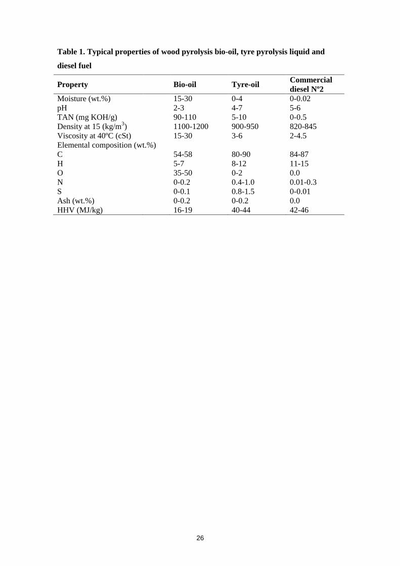
literature [5], see Table 1. As fuel, bio-oil has several environmental advantages over
fossil fuels since it is renewable, locally produced and has lower environmental impact
(close to CO2/GHG neutral, no SOx emissions, 50% lower NOx emissions) [3].
However, it presents some disadvantages for its application as fuel such as high water
content, high viscosity, poor ignition characteristics and corrosiveness [1], as well as
high oxygen content, high solids content and chemical instability [4]. Pyrolysis liquids
are unstable due to their high amount of reactive oxygen-containing compounds [6].
3
The instability is seen as a viscosity increase during storage, which, connected with the
formation of water, finally leads to the separation of a lignin-rich bottom sludge [7].
Due to their structural water, bio-oil has been shown to be immiscible with diesel oil or
other hydrocarbon fuels [8, 9]. Hence, an increasing number of methods for bio-oil
upgrading are being investigated and developed for improving the quality of bio-oil.
The processes to get improved bio-oils mainly include hydroprocessing and catalytic
cracking, although other processes such as esterification and reactive distillation have
been also evaluated [4].
On the other hand, scrap tyres are a non-destructible and non-biodegradable waste
through time making difficult their post-treatment and/or their recycling [10]. After their
life cycle, tyres become wastes and only a few can be re-used. As the disposal of scrap
tyres in landfills is prohibited in Europe, it is necessary to find an alternative route to
take advantage of their high potential as energetic and raw material source. There are
many different manufacturers and countless different formulations available all over the
world; being the composition of the tyres influenced by both the tyre grade and
manufacture processes. Consequently, the tyre pyrolysis, as a process to recover tyre
energy, offers products that may also vary in terms of yield, chemical composition and
characteristics. These properties depend not only on the source and grade of the tyres,
but also, on the reactor configuration, efficiency in heat transfer and experimental
conditions [10]. Even so, tyre pyrolysis liquids (a mixture of paraffins, olefins and
aromatic compounds) have been found to have almost coincidental results regarding the
marginal moisture and oxygen content. In addition, it is worth highlighting that some
physico-chemical properties of the tyre pyrolysis liquids are fairly comparable to those
found in commercial automotive diesel fuels, as shown in Table 1. These facts, together
with their miscibility with diesel fuel [11] have encouraged their use as a replacement
4
for conventional liquid fuels in compression ignition engines as showed in [12-14].
However, further studies are necessary to utilize tyre derived oils as a liquid fuel or
feedstock, since higher sulphur content and wider distillation range than commercial
fuels can be problematic.
Related to biomass and waste tyres co-pyrolysis, Cao et al. [15] concluded that co-
pyrolysis of sawdust and waste tyre using a fixed bed reactor can inhibit the unsuitable
formation of PAHs produced by pyrolysis of tyre alone. The authors also showed a
synergetic effect between both feedstock, which was reflected in an improvement of the
pyrolytic liquid quality in terms of density, viscosity and elemental composition when
compared to the liquid obtained from only biomass pyrolysis. Thus, it would be very
interesting to study the co-pyrolysis of both feedstock in a continuous facility such as an
auger reactor, since it is well-known that the type of reactor and process conditions
could lead to different properties of the liquid fuel. In fact, co-pyrolysis of wood
biomass and polymers such as polyethylene and polypropylene showed that the
composition and the nature of both, biomass and synthetic polymers, as well as
pyrolysis conditions have a great influence on the yield, the chemical structure and the
physical properties of products [16].
This study aims to evaluate the co-pyrolysis of forestry waste woodchips containing
bark and waste tyre scraps (using blends up to 20% of waste tyre) as a way for
upgrading the physico-chemical properties of the bio-oil obtained from merely biomass.
Co-pyrolysis of biomass with a feedstock of different composition could offer a simple
route for upgrading the bio-oil in one step avoiding or minimizing the need for
additional catalytic stages. In the first place, a thermogravimetric study was carried out
to determine the temperature interval where simultaneous devolatilization of both
feedstock takes place. Secondly, co-pyrolysis process was evaluated both in a fixed bed
5
reactor and in a continuous auger reactor, in which pyrolysis of scrap tyres [17, 18] and
forestry wastes [19] have been run successfully before. Finally, chemical and physical
properties of the different pyrolysis fractions obtained were determined for both
reactors.
2. Experimental
2.1 Feedstock
Pine woodchips (15 mm of nominal size) and waste-tyre scraps (5 mm of
nominal size) were used for the experiments. The biomass consisted of Aleppo pine
(Pinus halepensis) containing bark from forestry wastes and it was dried prior to the
experiments (moisture content of 4.0 wt.% ). The waste-tyre scraps were composed of
rubber without the steel thread and the textile netting (moisture content of 0.9 wt.% ).
The ultimate analysis of both materials was carried out in a Carlo Erba EA1108
instrument, the moisture content was determined according to ISO-589-1981; the ash
content was measured according to ISO-1171-1976 and the volatile matter was
determined according to ISO-5263-1974. The heating value was measured
experimentally with a calorimetric bomb IKA C-2000 and determined according to
UNE164001EX for the biomass and according to ISO-1929-76 for the waste-tyres.
Table 2 shows the feedstock characterisation.
2.2 Thermogravimetric analysis
Three experiments from room temperature to 700 ºC at 10 ºC/min were
performed for each feedstock and for a mixture of 80 wt.% biomass and 20 wt.% waste
tyre (80/20). This 80/20 mixture is the maximum blend of waste tyre present in the
feedstock since the aim of this paper is to upgrade the properties of the liquid fraction
6
obtained from solely biomass. The solid weight loss and temperature was recorded in a
thermobalance SETARAM Setsys. The sample weight used in all experiments was 20
mg and the carrier gas was nitrogen at 150 lN/min.
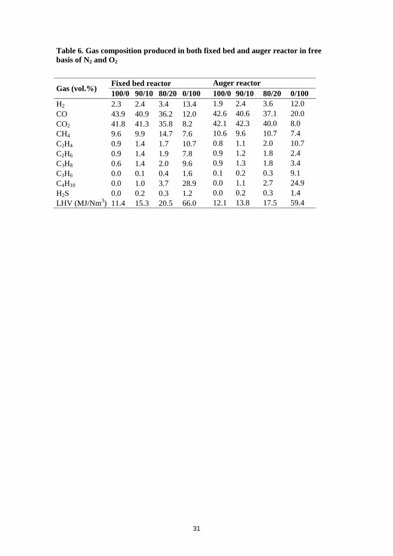
2.3 Fixed bed reactor
Pyrolysis was carried out in a kanthal fixed bed reactor (74 cm length and 1.6
cm internal diameter) in order to study feedstock devolatilisation in a small scale, see
Figure 1. Samples of 20 g were pyrolysed using nitrogen as carrier gas (0.8 lN/min)
previously preheated. The reactor was heated externally with an electrical heater at 80
ºC/min to the final pyrolysis temperature of 500 ºC. The reaction time was set to 15
minutes. An ice-cooled trap was used to collect the liquids. Liquid and solid yields were
obtained by weight, while the gas yield was calculated by the gas composition sampled
in a gas bag. Each run was performed three times and the value reported for each yield
is the average value with its absolute error. Different feedstock mixtures on mass basis
were studied in the fixed bed reactor: 100% of biomass (100/0); 90% of biomass and
10% of waste tyres (90/10); 80% of biomass and 20% of waste tyres (80/20) and 100%
waste tyres (0/100).
2.4 Auger reactor
In order to test the scalability of the process, an auger reactor pilot plant
described in detail in previous publications [17-19] was used. The experimental setup
presents an excellent reproducibility and stability and is able to process up to 15 kg/h of
wastes tyres. This supposed a thermal inlet power of around 150 kWth when merely
waste tyres are used as a feedstock. This type of reactor not only promotes the
7
continuity of the process, but also it controls key variables of the pyrolysis process such
as the mass flow rate and the residence time of the feedstock inside the reactor.
Experiments were set at 500ºC using nitrogen as carrier gas at 5 lN/min and a
mass flow rate of 5 kg/h. The residence time of the feedstock inside the reactor was
fixed in 5 min. Liquid and solid yields were obtained directly by weight, while the gas
yield was calculated by the gas composition sampled in the gas bags. Both liquid and
non-condensable gas samples were collected once the steady state was reached,
approximately after 45 minutes from the beginning of the experiment. As done for the
experiments carried out in the fixed bed reactor, the pyrolysis yields are the average
value of three repetitions. Liquid samples were sealed in bottles and kept refrigerated
prior to analysis. Co-pyrolysis of different feedstock mixtures was carried out using the
same proportion mixtures used in the fixed bed reactor and described above.
2.5 Product characterisation
Complete characterisation of the liquid fuel was carried out by ultimate
composition (Carlo Erba EA1108), calorific value (IKA C-2000), water content by
Karl-Fischer titration (Crison Titromatic) according to ASTM E203-96; total acid
number (TAN) and pH (Mettler Toledo T50), density (Antor-Paar DMA35N) and
viscosity (Brookfield LVDV-E). Qualitative Gas Chromatography/Mass Spectrometry
(GC/MS) analysis was performed in a THERMO Trace GC Ultra with MS DSQII to
identify the main compounds in the liquid fuel. Prior to analysis, the liquid samples
were filtered and diluted with methanol (1:10) in the case of the biomass samples and
with dichloromethane for the waste tyre samples. 200 ppm of 1-octanol were added as
internal standard. The capillary column was a DB-Petro (100 m x 0.25 mm ID x 0.50
μm film thickness) with helium as carrier gas with an initial flow of 2.3 ml/min during
8
the first 84 minutes, an increasing flow rate from 0.2 to 1.8 ml/min and kept at a
constant flow rate of 1.8 ml/min during the rest of the analysis. The oven temperature
was initially programmed at 40 ºC (4 min), after that a first heating rate was set at
1ºC/min up to 55 ºC, a second heating rate of 2 ºC/min to 185 ºC, a third heating rate of
10ºC/min to 250 ºC and finally held at 250 ºC for 60 min. The injector, the ion source
and the transfer line temperatures were kept constant at 300, 230 and 280ºC
respectively. A sample volume of 1 μl was injected applying 1:7 split mode. After a
solvent delay of 8 min for the biomass samples and 10.4 min for the waste tyre sample,
a full mass spectrum was acquired. The MS was operated in positive electron ionisation
mode and an m/z range from 30 to 500 was scanned. The voltage applied to the
multiplier detector was 1275 V in order to obtain the total ion chromatograms (TICs) in
a full-scan acquisition method. The identification of peaks is based on computer
matching of the mass spectra with the NIST library. Once the identification is carried
out, a Selective Ion Monitoring (SIM) chromatogram of the principal ion of each
compound is extracted from the full-scan spectra.
Furthermore, the solid fraction (char) was characterized by measuring its
calorific value (IKA C-2000). In addition, the non-condensable gases were determined
by gas chromatography using a Varian’s 490-GC PRO coupled to a TCD detector and
equipped with a Molsieve 5 Å column to analyse H2, O2, N2 and CO and with a
HayeSep column to analyse CO2, H2S and hydrocarbons. The oven programs used were
isothermal at 60 and 90 ºC for the Molsieve and Hayesep column respectively.
2.6 Synergetic effect
The occurrence of synergetic interactions for both the product yields and
properties was observed based on a comparison between the experimental pyrolysis
9
results and the theoretical pyrolysis data. Theoretical values were calculated from each
individual feedstock and their respective mass ratio, assuming that there are no
interactions among the pyrolytic vapour molecules (see equation 1). Herein, 1 and 2
represent the product yield or physico-chemical property from biomass and tyre,
respectively; while w1 and w2 are the mass proportion, from the aforementioned
feedstock, respectively. Thus, if the experimental co-pyrolysis is leading to a bio-oil
property value better than the y value, it can be concluded that a vapour interaction is
likely taking place and, consequently, a synergetic effect occurs.
2211 wwy (1)
It is worth highlighting that, in a strict sense, theoretical values of the different
liquid properties cannot be calculated since biomass bio-oils and tyre pyrolytic oils are
not miscible.
3 Results and discussion
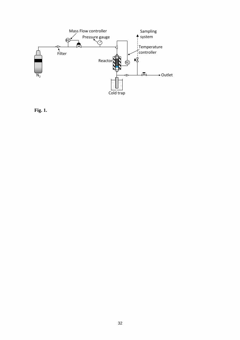
3.1 Thermogravimetric analysis
Wood decomposition takes place mainly in three steps [21]: first lignin
decomposition, which lasts until 500 ºC, followed by hemicellulose decomposition and,
finally, cellulose decomposition. Tyre pyrolysis has been also described elsewhere [20,
22, 23] and three main steps of devolatilisation are also found: a first step of low
reaction rates linked to pyrolysis of tyre rubber additives; a second step with a sharp
peak related to natural rubber decomposition and finally, a third step assigned to the
decomposition of synthetic rubber (styrene-butadiene rubber and butyl rubber).
The aim of the thermogravimetric analysis is to assess the thermal behaviour
under pyrolysis conditions of each feedstock and the biomass/waste tyre blend. The
work is focused on blends lower than 20 wt.% of waste tyres since the main objective is
10
to upgrade the liquid obtained from merely biomass pyrolysis. Figure 2 shows the TG as
well as the DTG plots for the three biomass/waste tyres samples used (100/0, 80/20 and
0/100). The theoretical values calculated for the blend as an additive reaction are also
included as showed by Zhou et al. [24]. As expected, biomass devolatilisation starts at
slightly lower temperature, approximately 200 ºC, than waste tyre devolatilisation.
Figure 2 also points out that the peak decomposition temperature (temperature of the
maximum rate of weight loss) of the blend is similar to that obtained for biomass
(around 361 °C) but lower than that found for waste tyre (372 °C).
From the thermograms, it can be established the devolatilisation temperature
window for possible interactions between both feedstock. The temperature ranges for
pyrolysis of biomass and tyre overlap at temperatures from 250 to 500 ºC. Thus,
radicals released during the pyrolysis process could coexist in this temperature range
and interactions between them are likely to occur. These interactions could produce
variations among the characteristics of the pyrolysis products, such as leading to a
single phase liquid fuel with improved properties. In fact, some differences can be
observed when comparing the experimental and the theoretical curves. The
experimental and theoretical weight loss curves are similar until 300 ºC, whereas mostly
biomass pyrolysis takes place. From this temperature the experimental curve of weight
loss lays over the theoretical one, increasing the difference up to 400 ºC and slightly
decreasing at higher temperatures. Secondary reactions produced from interactions
among radicals seem to increase the fraction of solid remaining for the blend sample
likely due to the adsorption of these volatile compounds on its porosity as showed
elsewhere [20].
The facts described above are more accurately observed in the rate of weight
loss. The experimental curve is lower than the theoretical one from 250 to 375 ºC, when
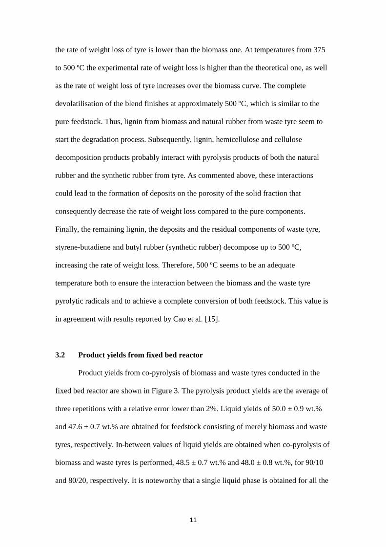
11
the rate of weight loss of tyre is lower than the biomass one. At temperatures from 375
to 500 ºC the experimental rate of weight loss is higher than the theoretical one, as well
as the rate of weight loss of tyre increases over the biomass curve. The complete
devolatilisation of the blend finishes at approximately 500 ºC, which is similar to the
pure feedstock. Thus, lignin from biomass and natural rubber from waste tyre seem to
start the degradation process. Subsequently, lignin, hemicellulose and cellulose
decomposition products probably interact with pyrolysis products of both the natural
rubber and the synthetic rubber from tyre. As commented above, these interactions
could lead to the formation of deposits on the porosity of the solid fraction that
consequently decrease the rate of weight loss compared to the pure components.
Finally, the remaining lignin, the deposits and the residual components of waste tyre,
styrene-butadiene and butyl rubber (synthetic rubber) decompose up to 500 ºC,
increasing the rate of weight loss. Therefore, 500 ºC seems to be an adequate
temperature both to ensure the interaction between the biomass and the waste tyre
pyrolytic radicals and to achieve a complete conversion of both feedstock. This value is
in agreement with results reported by Cao et al. [15].
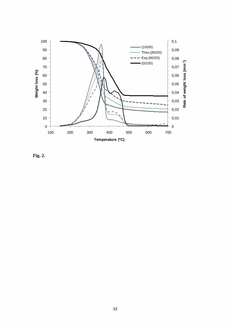
3.2 Product yields from fixed bed reactor
Product yields from co-pyrolysis of biomass and waste tyres conducted in the
fixed bed reactor are shown in Figure 3. The pyrolysis product yields are the average of
three repetitions with a relative error lower than 2%. Liquid yields of 50.0 ± 0.9 wt.%
and 47.6 ± 0.7 wt.% are obtained for feedstock consisting of merely biomass and waste
tyres, respectively. In-between values of liquid yields are obtained when co-pyrolysis of
biomass and waste tyres is performed, 48.5 ± 0.7 wt.% and 48.0 ± 0.8 wt.%, for 90/10
and 80/20, respectively. It is noteworthy that a single liquid phase is obtained for all the
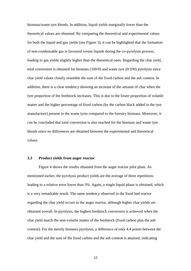
12
biomass/waste tyre blends. In addition, liquid yields marginally lower than the
theoretical values are obtained. By comparing the theoretical and experimental values
for both the liquid and gas yields (see Figure 3), it can be highlighted that the formation
of non-condensable gas is favoured versus liquids during the co-pyrolysis process,
leading to gas yields slightly higher than the theoretical ones. Regarding the char yield,
total conversion is obtained for biomass (100/0) and waste tyre (0/100) pyrolysis since
char yield values closely resemble the sum of the fixed carbon and the ash content. In
addition, there is a clear tendency showing an increase of the amount of char when the
tyre proportion of the feedstock increases. This is due to the lower proportion of volatile
matter and the higher percentage of fixed carbon (by the carbon black added in the tyre
manufacture) present in the waste tyres compared to the forestry biomass. Moreover, it
can be concluded that total conversion is also reached for the biomass and waste tyre
blends since no differences are obtained between the experimental and theoretical
values.
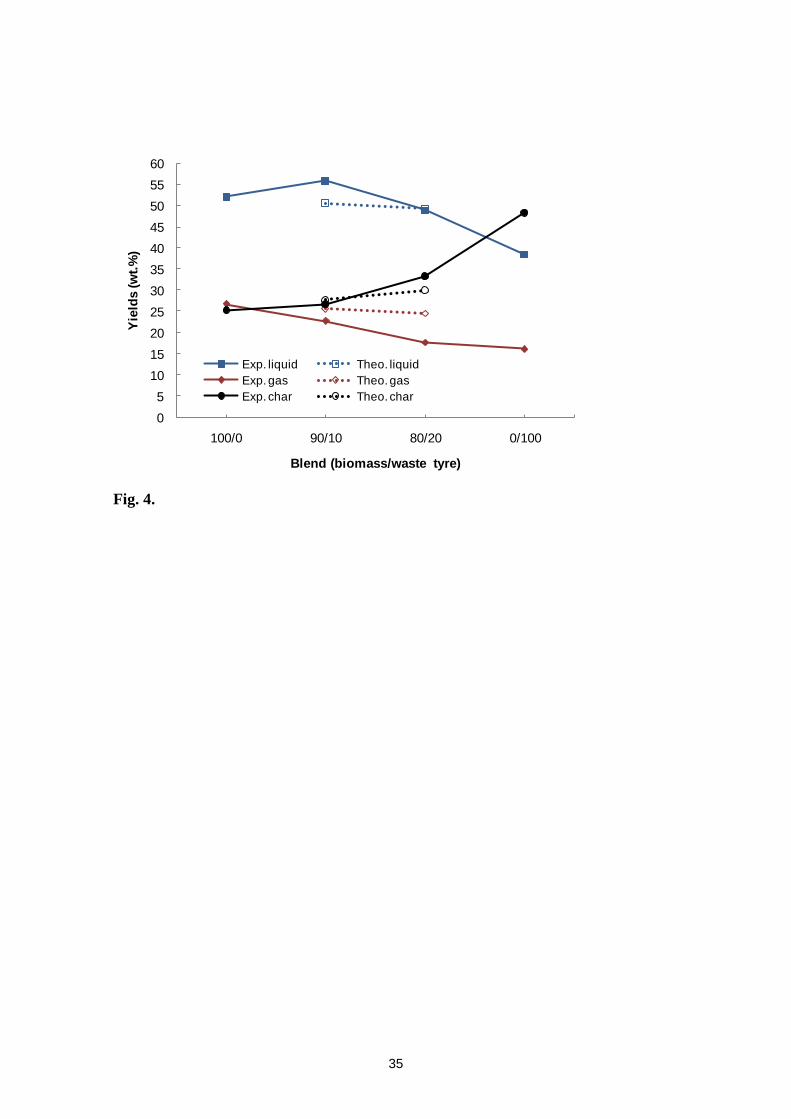
3.3 Product yields from auger reactor
Figure 4 shows the results obtained from the auger reactor pilot plant. As
mentioned earlier, the pyrolysis product yields are the average of three repetitions
leading to a relative error lower than 3%. Again, a single liquid phase is obtained, which
is a very remarkable result. The same tendency observed in the fixed bed reactor
regarding the char yield occurs in the auger reactor, although higher char yields are
obtained overall. In pyrolysis, the highest feedstock conversion is achieved when the
char yield match the non-volatile matter of the feedstock (fixed carbon plus the ash
content). For the merely biomass pyrolysis, a difference of only 4.4 points between the
char yield and the sum of the fixed carbon and the ash content is attained, indicating
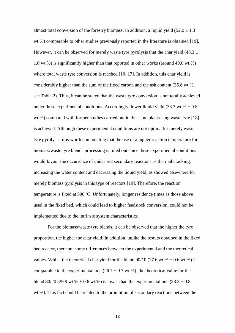
13
almost total conversion of the forestry biomass. In addition, a liquid yield (52.0 ± 1.3
wt.%) comparable to other studies previously reported in the literature is obtained [19].
However, it can be observed for merely waste tyre pyrolysis that the char yield (48.3 ±
1.0 wt.%) is significantly higher than that reported in other works (around 40.0 wt.%)
where total waste tyre conversion is reached [10, 17]. In addition, this char yield is
considerably higher than the sum of the fixed carbon and the ash content (35.8 wt.%,
see Table 2). Thus, it can be stated that the waste tyre conversion is not totally achieved
under these experimental conditions. Accordingly, lower liquid yield (38.3 wt.% ± 0.8
wt.%) compared with former studies carried out in the same plant using waste tyre [18]
is achieved. Although these experimental conditions are not optima for merely waste
tyre pyrolysis, it is worth commenting that the use of a higher reaction temperature for
biomass/waste tyre blends processing is ruled out since these experimental conditions
would favour the occurrence of undesired secondary reactions as thermal cracking,
increasing the water content and decreasing the liquid yield, as showed elsewhere for
merely biomass pyrolysis in this type of reactors [19]. Therefore, the reaction
temperature is fixed at 500 ºC. Unfortunately, longer residence times as those above
used in the fixed bed, which could lead to higher feedstock conversion, could not be
implemented due to the intrinsic system characteristics.
For the biomass/waste tyre blends, it can be observed that the higher the tyre
proportion, the higher the char yield. In addition, unlike the results obtained in the fixed
bed reactor, there are some differences between the experimental and the theoretical
values. Whilst the theoretical char yield for the blend 90/10 (27.6 wt.% ± 0.6 wt.%) is
comparable to the experimental one (26.7 ± 0.7 wt.%), the theoretical value for the
blend 80/20 (29.9 wt.% ± 0.6 wt.%) is lower than the experimental one (33.3 ± 0.8
wt.%). This fact could be related to the promotion of secondary reactions between the
14
waste tyre and biomass radicals, leading to char formation. Moreover, it can be
observed that the liquid yield decreases with the tyre proportion in the blend. The
highest liquid yield is found for the 90/10 blend (56.0 ± 1.6 wt.%), which is remarkably
higher than both the yield obtained in the fixed bed reactor (48.5 ± 0.7 wt.%) and the
theoretical value (50.6 wt.% ± 1.3 wt.%). In addition, this value is higher than that
obtained for the pyrolysis of merely biomass. This result suggests a synergetic effect
towards the production of bio-oils between both feedstock at those experimental
conditions, which could be again related to the promotion of interactions between
biomass and waste tyre radicals leading to the formation of bio-oil. A different
behaviour is observed for the 80/20 blend. In this case, the liquid yield is comparable to
that obtained for the fixed bed (48.0 ± 0.8 wt.%) and to the theoretical value (49.2 wt.%
± 1.2 wt.%). As the char yield obtained is remarkably higher than the theoretical value,
it can be again stated that the presence of higher proportion of waste tyre in the blend is
likely increasing the probability of radical interactions, promoting the formation of char
instead of bio-oil. In agreement with these results, it is obtained that gas yields decrease
with increasing waste tyre proportion in the blend, being this effect more apparent for
the 80/20 blend. In addition, it is also observed that the theoretical values are higher
than the experimental ones, which is again showing that the addition of waste tyres to
the pyrolysis process is promoting the occurrence of radical interactions. It can be
concluded that although the presence of waste tyre in the blend is promoting the
interaction of pyrolysis radicals towards bio-oil production, the proportion of waste tyre
in the blend should be kept low since char formation could be increased, as it is
observed for the 80/20 blend.
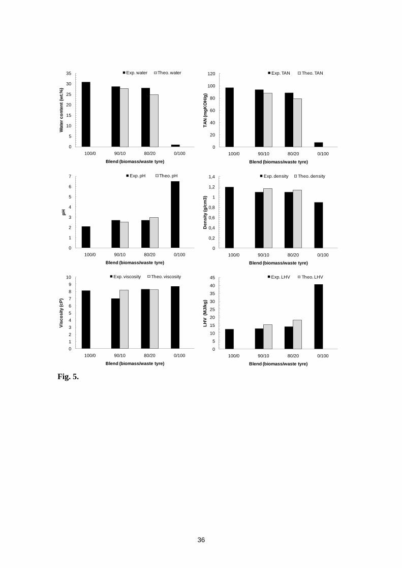
3.4 Product characterisation
15
3.4.1 Liquid characterisation
As mentioned previously, no phase separation is evidenced in the liquid fraction
for all the blends considered in both reactors. According to Chiaramonti et al. [25] water
contents higher than 30 wt.% lead to phase separation, forming two phases with
different properties. Multi-phase liquids can be due to high moisture content in the
feedstock as well as to the chemical composition of the original biomass feedstock [5].
The water present in bio-oils, when is lower than 30 wt.%, is usually miscible with the
oligomeric lignin-derived components because of the solubilizing effect of other polar
hydrophilic compounds [1]. As it is shown in Figs. 5 and 6, the water content in the
liquid fractions for both reactors is lower than 30 wt.%, which explains the formation of
a single phase bio-oil for the merely biomass pyrolysis experiment. Additionally, it
should be highlighted that since biomass bio-oils and tyre pyrolytic oils are not miscible
even at low waste tyre bio-oil ratios, it can be assumed that radical interaction during
the pyrolysis reaction leads to a new bio-oil that avoids phase separation.
Generally speaking, the properties of the liquid produced in the fixed bed reactor
(Figure 5) show a slight decrease on both the water content and TAN, compared to
those obtained with merely biomass. In addition, pH and calorific value increase whilst
the O content decreases (Table 3). This suggests a positive effect on these properties
when the waste tyre content increases in the blend. However, the improvement obtained
for all these properties is lower than that expected from the pure feedstock pyrolysis. As
shown in Figure 5, the experimental values for these properties are poorer than the
hypothetic theoretical ones. This fact could be related to the intrinsic characteristics of
the fixed bed reactor. Reaction radicals are slowly released and quickly evacuated from
the reactor, which is decreasing the probability of interactions between biomass and
waste tyre radicals. It is worth commenting that some radical interactions are still taking
16
place since a single phase is obtained whilst biomass bio-oils and tyre pyrolytic oils are
not miscible even at low waste tyre bio-oil ratios.
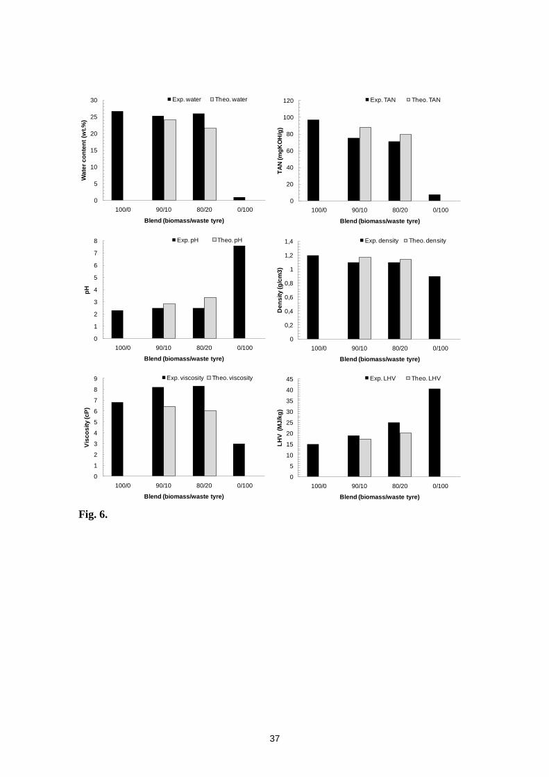
On the other hand, experimental results from the auger reactor reveal a
remarkable upgrading for some liquid properties. Thus, a positive interaction between
both feedstock seems to take place resulting in upgraded properties such as lower TAN,
lower density, higher pH, higher calorific value and lower oxygen content (see Fig. 6
and Table 4). In addition, the experimental values for these properties (except for pH
and oxygen content), are better than the theoretical ones, showing a synergetic effect.
As showed in Fig. 6, after waste tyre addition TAN decreases from 97.0 to 75.1
and to 71.1 mg KOH/g for the 90/10 and 80/20 blends, respectively. Accordingly, pH
values slightly increase from 2.3 to 2.5. As pointed out by Bhattacharya et al. [26], pH
values mainly reflect the presence of carboxylic acids, such as formic, acetic and
propanoic acids, generated due to cellulose and hemicellulose pyrolytic degradation,
whilst TAN gives a better tendency about the amount of acidic compounds present in
the liquid. It is worth commenting that although a 80/20 blend leads to lower TAN
values, the synergic effect is more apparent for the 90/10 blend. In agreement with these
results, it can be observed in Table 5 that the area ratios of acidic compounds identified
by GC/MS is always reduced after the addition of waste tyres and that the positive
effect is relatively higher for the 90/10 blend. Against this background, it should be
pointed out that even though acidity is improved and the concentration of these
compounds is reduced, a further bio-oil upgrading should be performed for its
application as fuel in standard engines, where a value lower than 10 is accepted in order
to avoid corrosiveness problems and deposits formation [27].
Remarkably, LHV is the property with the major upgrading since it changes
from 14.9 to 19.0 and to 25.0 MJ/kg for the 90/10 and 80/20 blends, respectively. Thus,
17
it shows an increase up to 27 % and to 70 %, respectively. Albeit a synergetic effect is
observed for both blends, this effect is more significant for the 80/20 blend. A
noteworthy fact is that a remarkably higher LHV is achieved despite of this bio-oil has a
higher water content than that theoretically expected. Higher LHV could lead to
substantial higher thermal efficiencies than bio-oil from merely biomass, when is used
as fuel in modified internal combustion engines. According to Yang et al. [28], the
heating value has the major effect on engine thermal efficiency and power output. An
increase in the heating value of a fuel will increase the engine power output for the same
fuel consumption rate given the increase of both thermal input and efficiency.
Moreover, it is found that the C and H contents in the liquid gradually increase
with the proportion of waste tyres in the feedstock, whilst the O content decreases
(Table 4), supporting the data obtained for the calorific value. Table 4 also shows that
the experimental C and H contents are poorer than those theoretically expected. A
higher water content than that theoretically expected in the bio-oil could explain this
fact. The water in the bio-oil comes mainly from water in the biomass and dehydration
during pyrolysis. Since water in the biomass is comparable for all the experiments, it
can be assumed that the addition of waste tyre to the feedstock blend also promotes
dehydration reactions, being this effect more apparent at higher waste tyre ratios. It can
be assumed that the presence of some additives in the waste tyres, such as CaO [29], is
favouring dehydration reactions. Density also decreases from 1.2 to 1.1 g/cm3 as the
waste tyre increases in the blend. However, these values are still higher than those found
in standard fuels such as distillate marine fuels (0.89-0.90 g/cm3) and residual fuels
(around 1.0 g/cm3) as found in standard ISO 8217.
Regarding viscosity, results disagree with the behaviour theoretically expected.
The viscosity increases as the tyre ratio increases in the blend, since for merely waste
18
tyre the lowest value is found. Again, this result suggests that waste tyre radicals
released in the auger reactor favour radical interactions, leading to the formation of
higher molecular weight organic compounds, which, in turn, increase the viscosity of
the liquid fraction. Unfortunately, this assumption could not be confirmed by GC/MS
analysis since heavier compounds than methyl-phenanthrene could not be analysed.
Representative bio-oil samples of the four feeding blends obtained in the auger
reactor (100/0, 90/10, 80/20 and 0/100 of biomass/waste tyre blends) are also analysed
by means of qualitative GC/MS using 1-octanol as internal standard. A total of 180
compounds are identified, of which 75 belonged to the 100% biomass samples and 115
to the 100% waste tyre sample. Table A1 in the supplementary data shows the identified
compounds with their area ratio (average of the compound area divided by the area of
the internal standard) for all the blends. It can be observed that new compounds are not
formed during the co-pyrolysis process of biomass/waste tyre blends compared to the
pyrolysis of the pure feedstock. In addition, all the compounds detected in the pyrolysis
of merely biomass are present in the blend samples whilst only ten compounds detected
during the pyrolysis of merely waste tyre are also identified in the blend samples. These
ten compounds (from highest to lowest abundance) are limonene; p-xylene; toluene;
1,2,3-trimethylbenzene; 1-ethyl-4-methylbenzene; 1,3,5,5-Tetramethyl-1,3-
cyclohexadiene; 1,3-dimethylbenzene; benzene; 1,3-cyclopentadiene; and 1-methyl-1,4-
cyclohexadiene. Therefore, it can be concluded that the addition of low amounts of
waste tyre to the feedstock blend only slightly alters the nature of the bio-oil although
an upgraded bio-oil is obtained. Thus, the main compounds present in the biomass and
waste tyre blends (above 3 of the area ratio) are mainly levoglucosan, furfural, phenols,
acids, esters, aldehydes, ketones and limonene (see Table 5). During pyrolysis of
holocellulose (hemicellulose and cellulose), two competing pyrolytic pathways are
19
mainly responsible for its primary decomposition, depolymerisation and pyrolytic ring
scission. Depolymerisation process forms various anhydrosugars (mainly levoglucosan),
furans and other products [30]. As shown in Table 5, the levoglusocan area ratio is only
slightly reduced with increasing waste tyre in the feedstock bled. Thus, although it
cannot completely rule out, it seems that secondary reactions between primary
holocellulose decomposition products and waste tyre radicals are unlikely to take place.
In agreement with this, aldehydes and ketones, which are the main products formed
from the pyrolytic ring scission of holocellulose, are reduced according to the
proportion of waste tyre added to the blend. Area ratios of both, aldehydes and ketones,
are reduced around 10 % and around 20 % for the 90/10 and 80/20 blends, respectively.
Particular attention should be paid to the aldehydes since they pose a big threat to the
stability of the crude bio-oil [31]. Secondary degradation reactions may occur, since
phenolic compounds tend to polymerize with aldehydes under acidic conditions [32].
Therefore, it can be highlighted that the relative content of the aldehydes is decreased
after waste tyre addition, which is beneficial for improving the stability of bio-oils. On
the other hand, phenolic compounds are originated from the decomposition of lignin
[30, 33, 34]. In addition to their influence on the bio-oil instability, it is well-known that
the lignin-derived products are mainly responsible for the high molecular weight and
viscosity of bio-oils and thus, one of the aims of any upgrading process is to remove
these compounds. It can be observed in Table 5 that the area ratio of these compounds is
significantly decreased for the biomass/waste tyre blends, being this reduction about 20
% and about 40 % for the 90/10 and 80/20 blends, respectively. Thus, a synergic effect
towards phenolic compounds removal is taking place. Since experimental gas yields are
lower than the theoretical values for the biomass/waste tyre blends and the
concentration of aromatic compounds is not affected by the amount of waste tyre in the
20
feedstock, it can be assumed that phenol precursors are likely interacting with waste tyre
radicals to form heavier liquid compounds or char, depending on the amount of waste
tyre added to the biomass feedstock. Therefore, it can be observed that the addition of
waste tyres to the feedstock blend is significantly decreasing the amount of aldehydes
and phenolic compounds, which is beneficial for improving the stability of the new bio-
oils. Indeed, the viscosity of the biomass/waste tyre blends was measured after six
months and no significant changes were appreciated. Therefore, it can be concluded that
the addition of waste tyres to the biomass feedstock in an auger reactor is a potential
way for upgrading the quality of bio-oils. However, reactor size and process conditions
should be optimised so that interactions between waste tyre and biomass radicals could
be tuned to promote bio-oil production even at high waste tyre contents in the feedstock.
3.4.2 Char characterisation
No major differences are found regarding the reactor effect on the calorific value
of the char. The LHV of char obtained from both reactors is around 30 MJ/kg. This high
energy content could be very attractive for combustion processes since LHV is higher
than that found in some coals used for power generation and/or thermal applications
[35].
3.4.3 Non-condensable gas characterisation
Generally speaking, a similar trend can be noticed in both facilities. As expected,
the concentration of heavier hydrocarbons and hydrogen of the gas fraction produced in
both reactors increases as the amount of waste tyres increases in the fed (Table 6).
Similarly, H2S concentration increases with the waste tyre ratio in the blend, given its
higher concentration of S (Table 2). In contrast, CO and CO2 decrease proportionally as
the proportion of waste tyre increases. It is worth pointing out that the incorporation of
waste tyre to the feeding blend leads to the formation of heavier hydrocarbons, such as
21
C3H6 and C4H10. As a consequence, the LHV increases with the waste tyre ratio in the
blend. For the 80/20 blend, this value is 20.5 MJ/Nm3 when the process is conducted in
the fixed bed reactor and 17.5 MJ/Nm3 when the process is performed using the auger
reactor. This value is remarkably higher than that found for merely biomass pyrolysis
(12 – 13 MJ/Nm3), and hence, can likely contribute with the energy demand for driving
the co-pyrolysis process.
Conclusions
Pyrolysis process has been performed in a fixed bed reactor and in an auger
reactor pilot plant. In both systems it has been observed that the addition of waste tyres
to the biomass feedstock is improving the bio-oil properties and, remarkably, one phase
is obtained. It has been found that bio-oils with improved properties are attained for the
auger reactor and even a synergetic effect is observed for some of them. Radical
interactions between waste tyres and biomass pyrolysis products can promote the
formation of a stable bio-oil with upgraded properties.
Acknowledgments
The authors would like to thank the Aragon Regional Government (DGA) and
the Caixa Bank for financial support (Project GA-LC-015/2011). Authors also thank
MINECO and FEDER funds for providing partial support for this work (project
CTQ2012-37984-C02-01). Juan D. Martínez thanks to Fundación Carolina for his
fellowship as well as the Enlaza-Mundos Program. Part of the research carried out at
UAB has been funded by MICINN (CTQ2009-13873).
22
References
[1] A. Oasmaa, S. Czernik. Fuel oil quality of biomass pyrolysis oils – state of the art
for the end users, Energ. Fuels 13 (1999) 914-921.
[2] S. Czernick, A.V. Bridgwater, Overview of applications of biomass fast pyrolyisis
oils, Energ. Fuels 18 (2004) 590-598.
[3] D. Mohan, C.U. Pittman, P.H. Steele, Pyrolysis of wood/biomass for bio-oil: a
critical review, Energ. Fuels 20 (2006) 848-889.
[4] A.V. Bridgwater, Review of fast pyrolysis of biomass and product upgrading,
Biomass Bioenergy 38 (2012) 68-94.
[5] A. Oasmaa, C. Peacocke, A guide to physical property characterisation of biomass
derived fast pyrolysis liquids. Technical research centre of Finland, Espoo, Finland,
2001, VTT Publication No. 450.
[6] A. Oasmaa, E. Huoppala, J.F. Selin, S. Gust, Y. Solantausta, Fast pyrolysis of
forestry residue and pine. 4. Improvement of product quality by solvent addition, Energ.
Fuels 18 (2004) 1578-1583.
[7] A. Oasmaa, E. Leppämäki, P. Koponen, J. Levander, A. Tapola, Physical
characterisation of biomass-based pyrolysis liquids. Application of standard fuel oil
analysis. Technical research centre of Finland, Espoo, Finland, 1997, VTT Publication
No 306.
[8] E. Taarning, C.M. Osmundsen, X. Yang, B. Voss, S.I. Andersen, C.H. Christensen,
Zeolite-catalyzed biomass conversion to fuels and chemicals, Energy Environ. Sci. 4
(2011) 793-804.
[9] M. Ikura, M. Stanciulescu, E. Hogan, Emulsification of pyrolysis derived bio-oil in
diesel fuel, Biomass Bioenergy 24 (2003) 221-232.
[10] J.D. Martínez, N. Puy, R. Murillo, T. García, M.V. Navarro, A.M. Mastral. Waste
tyre pyrolysis – A review, Renew. Sust. Energ. Rev. 23 (2013) 179-213.
[11] M.R. Islam, H. Haniu, M.R.A. Beg, Liquid fuels and chemicals from pyrolysis of
motorcycle tire waste, Fuel 87 (2008) 3112-3122.
[12] C. İlkılıç, H. Aydin, Fuel production from waste vehicle tires by catalytic pyrolysis
and its application in diesel engine, Fuel Process. Technol. 92 (2011) 1129-1135.
[13] O. Doğan, M.B. Çelik, B. Özdalyan, The effect of tire derived fuel/diesel fuel
blends utilization on diesel engine performance and emissions, Fuel 95 (2012) 340-346.
[14] J.D. Martínez, J. Rodríguez-Fernández, J. Sánchez-Valdepeñas, R. Murillo, T.
García. Performance and emissions of an automotive diesel engine using a tire pyrolysis
liquid blend, Fuel 115 (2014) 490-499.
23
[15] Q. Cao, L. Jin, W. Bao, Y. Lv, Investigations into the characteristics of oils
produced from co-pyrolysis of biomass and tire, Fuel Process. Technol. 90 (2009) 337-
342.
[16] P. Rutkowski, Influence of zinc chloride addition on the chemical structure of bio-
oil obtained during co-pyrolysis of wood/synthetic polymer blends, Waste Manage. 29
(2009) 2983-2993.
[17] E. Aylón, A. Fernández-Colino, M.V. Navarro, R. Murillo, T. Garcia, A.M.
Mastral, Waste tire pyrolysis: comparison between fixed bed reactor and moving bed
reactor, Ind. Eng. Chem. Res. 47 (2008) 4029-4033.
[18] E. Aylón, A. Fernández-Colino, R. Murillo, M.V. Navarro, T. García, A.M.
Mastral, Valorisation of waste tyre by pyrolysis in a moving bed reactor, Waste
Manage. 30 (2010) 1220-1224.
[19] N. Puy, R. Murillo, M.V. Navarro, J.M. López, J. Rieradevall, G. Fowler, I.
Aranguren, T. Garcia, J. Bartrolí, A.M. Mastral, Valorisation of forestry waste by
pyrolysis in an auger reactor, Waste Manage. 31 (2011) 1339-1349.
[20] R. Murillo, E. Aylón, M.V. Navarro, M.S. Callén, A. Aranda, A.M. Mastral, The
application of thermal processes to valorise waste tyre, Fuel Process. Technol. 87
(2006) 143-147.
[21] M.V. Navarro, R. Murillo, A.M. Mastral, N. Puy, J. Bartroli, Application of the
distributed activation energy model to biomass and biomass constituents
devolatilization, AIChE J. 55 (2009) 2700-2715.
[22] P.T. Williams, S. Besler, Pyrolysis-thermogravimetric analysis of tyres and tyre
components, Fuel 14 (1995) 1277-1283.
[23] J. Yang, C. Roy, A new method for DTA measurement of enthalpy change during
the pyrolysis of rubbers, Thermochim. Acta 288 (1996) 155 168.
[24] L. Zhou, Y. Wang, Q. Huang, J. Cai, Thermogravimetric characteristics and
kinetics of plastic and biomass blends co-pyrolysis, Fuel Process. Technol. 87 (2006)
963-969.
[25] D. Chiaramonti, A. Oasmaa, Y. Solantausta, Power generation using fast pyrolysis
liquids from biomass, Renew. Sust. Energ. Rev. 11 (2007) 1056–1086.
[26] P. Bhattacharya, P.H. Steele, E.B.M. Hassan, B. Mitchell, L. Ingram, C.U. Pittman
Jr, Wood/plastic co-pyrolysis in an auger reactor: chemical and physical analysis of the
products, Fuel 88 (2009) 1251-1260.
[27] D.R. Daugaard, K. Gong, A. Platon, S.T. Jones, Process for producing high quality
pyrolysis oil from biomass, US Patent 2012/0108860 A1 [accessed 09.01.2013].
24
[28] Y. Yang, J.G. Brammer, M. Ouadi, J. Samanya, A. Hornung, H.M. Xu, Y. Li,
Characterisation of waste derived intermediate pyrolysis oils for use as diesel engine
fuels, Fuel 103 (2013) 247–257
[29] Y. Lin, C. Zhang, M. Zhang, J. Zhang, Deoxygenation of bio-oil during pyrolysis
of biomass in the presence of CaO in a fluidized-bed reactor, Energ. Fuels 24 (2010)
5686-5695.
[30] C. Branca, P. Giudicianni, C. Di Blasi, GC/MS characterization of liquids
generated from low-temperature pyrolysis of wood, Ind. Eng. Chem. Res. 42 (2003)
3190-3202.
[31] M.R. Djokic, T. Dijkmans, G. Yildiz, W. Prins, K.M. Van Geem, Quantitative
analysis of crude and stabilized bio-oils by comprehensive two-dimensional gas-
chromatography, J. Chromatogr. A. 1257 (2012) 131-140.
[32] J.N. Murwanashyaka, H. Pakdel, C. Roy, Step-wise and one-step vacuum pyrolysis
of birch-derived biomass to monitor the evolution of phenols, J. Anal. Appl. Pyrol. 60
(2001) 219-23.
[33] E.M. Hassan, F. Yu, L. Ingram, P. Steele, The potential use of whole-tree biomass
for bio-oil fuels, Energ. Source. Part A. 31 (2009) 1829-1839.
[34] A. Oasmaa, E. Kuoppala, Fast pyrolysis of forestry residue. 3. Storage stability of
liquid fuel. Energ. Fuels 17 (2003) 1075-1084.
[35] S.W. Parr. The classification of coal. Ind. Eng. Chem. 14 (1922) 919–922.
25
Figure Captions
Figure 1. Kanthal fixed bed reactor diagram.
Figure 2. TG and DTG for biomass, waste tyre and 80/20 blend. Black solid line for
merely waste tyre. Gray solid line for merely biomass. Green dotted line for theoretical
behavior of the 80/20 blend and purple dashed line for experimental behavior of the
80/20 blend.
Figure 3. Product yields produced in the fixed bed reactor. Solid lines for experimental
results and dashed lines for theoretical values; ■ in blue for experimental liquid yield, □
in blue for theoretical liquid yield; ♦ in red for experimental gas yield, ◊ in red for
theoretical gas yield; in black for experimental char yield, ○ in black for theoretical
char yield.
Figure 4. Product yields produced in the auger reactor. Solid lines for experimental
results and dashed lines for theoretical values; ■ in blue for experimental liquid yield, □
in blue for theoretical liquid yield; ♦ in red for experimental gas yield, ◊ in red for
theoretical gas yield; in black for experimental char yield, ○ in black for theoretical
char yield.
Figure 5. Some properties of the liquid fraction produced in the fixed bed reactor. Black
colour for experimental values; gray colour for theoretical values.
Figure 6. Some properties of the liquid fraction produced in the auger reactor. Black
colour for experimental values; gray colour for theoretical values.
26
Table 1. Typical properties of wood pyrolysis bio-oil, tyre pyrolysis liquid and
diesel fuel
Property Bio-oil Tyre-oil Commercial
diesel Nº2
Moisture (wt.%) 15-30 0-4 0-0.02
pH 2-3 4-7 5-6
TAN (mg KOH/g) 90-110 5-10 0-0.5
Density at 15 (kg/m3) 1100-1200 900-950 820-845
Viscosity at 40ºC (cSt) 15-30 3-6 2-4.5
Elemental composition (wt.%)
C 54-58 80-90 84-87
H 5-7 8-12 11-15
O 35-50 0-2 0.0
N 0-0.2 0.4-1.0 0.01-0.3
S 0-0.1 0.8-1.5 0-0.01
Ash (wt.%) 0-0.2 0-0.2 0.0
HHV (MJ/kg) 16-19 40-44 42-46
27
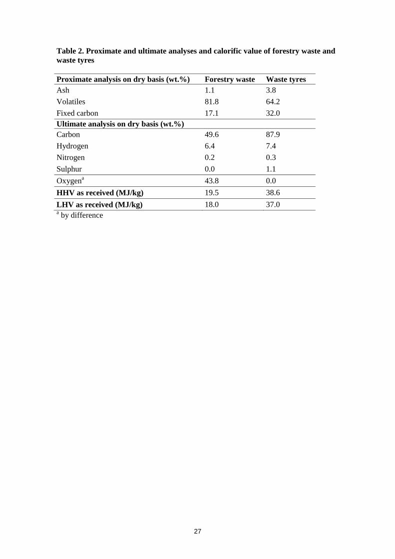
Table 2. Proximate and ultimate analyses and calorific value of forestry waste and
waste tyres
Proximate analysis on dry basis (wt.%) Forestry waste Waste tyres
Ash 1.1 3.8
Volatiles 81.8 64.2
Fixed carbon 17.1 32.0
Ultimate analysis on dry basis (wt.%)
Carbon 49.6 87.9
Hydrogen 6.4 7.4
Nitrogen 0.2 0.3
Sulphur 0.0 1.1
Oxygena 43.8 0.0
HHV as received (MJ/kg) 19.5 38.6
LHV as received (MJ/kg) 18.0 37.0 a by difference
28
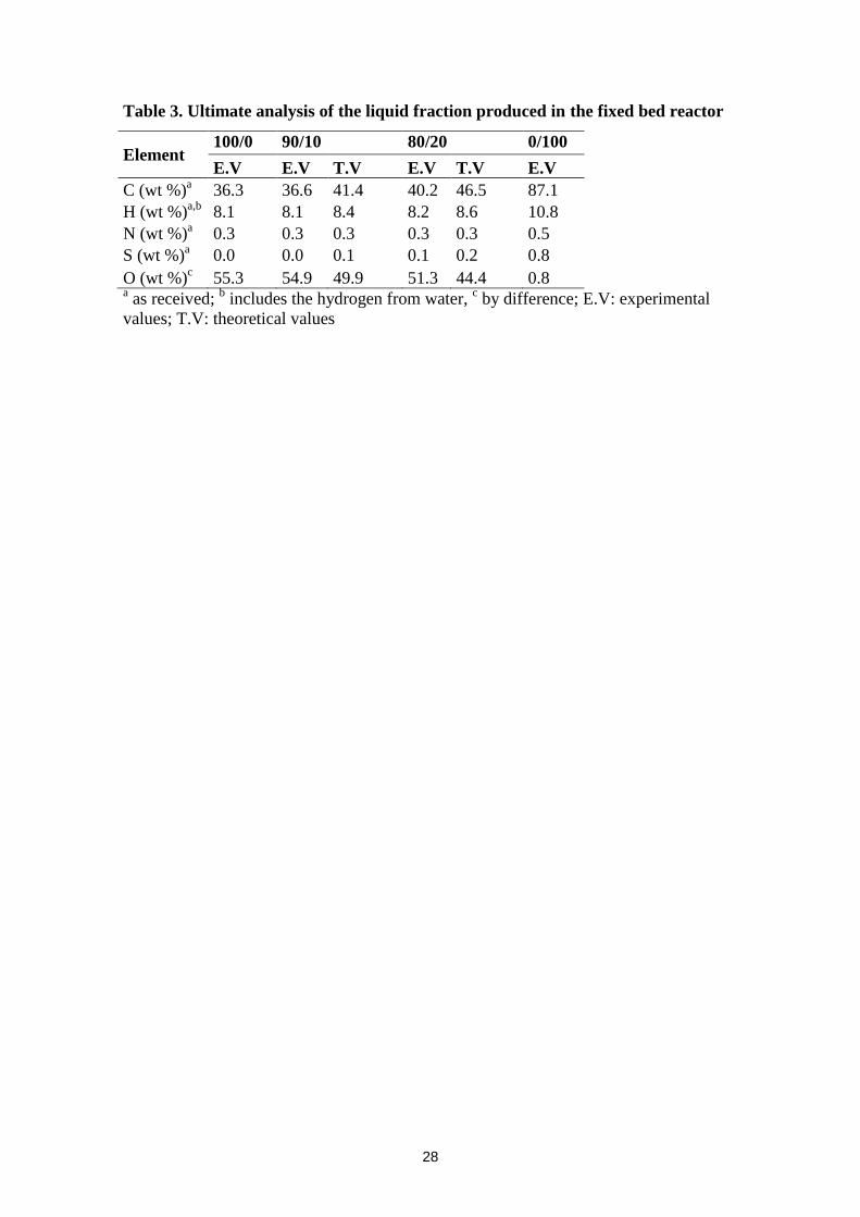
Table 3. Ultimate analysis of the liquid fraction produced in the fixed bed reactor
Element 100/0 90/10 80/20 0/100
E.V E.V T.V E.V T.V E.V
C (wt %)a 36.3 36.6 41.4 40.2 46.5 87.1
H (wt %)a,b
8.1 8.1 8.4 8.2 8.6 10.8
N (wt %)a 0.3 0.3 0.3 0.3 0.3 0.5
S (wt %)a 0.0 0.0 0.1 0.1 0.2 0.8
O (wt %)c 55.3 54.9 49.9 51.3 44.4 0.8
a as received;
b includes the hydrogen from water,
c by difference; E.V: experimental
values; T.V: theoretical values
29
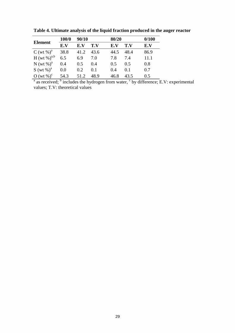
Table 4. Ultimate analysis of the liquid fraction produced in the auger reactor
Element 100/0 90/10 80/20 0/100
E.V E.V T.V E.V T.V E.V
C (wt %)a 38.8 41.2 43.6 44.5 48.4 86.9
H (wt %)a,b
6.5 6.9 7.0 7.8 7.4 11.1
N (wt %)a 0.4 0.5 0.4 0.5 0.5 0.8
S (wt %)a 0.0 0.2 0.1 0.4 0.1 0.7
O (wt %)c 54.3 51.2 48.9 46.8 43.5 0.5
a as received;
b includes the hydrogen from water,
c by difference; E.V: experimental
values; T.V: theoretical values
30
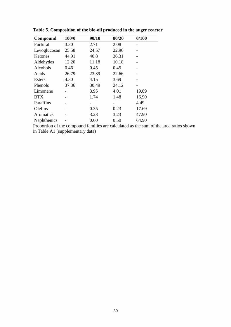
Table 5. Composition of the bio-oil produced in the auger reactor
Compound 100/0 90/10 80/20 0/100
Furfural 3.30 2.71 2.08 -
Levoglucosan 25.58 24.57 22.96 -
Ketones 44.91 40.8 36.31 -
Aldehydes 12.20 11.18 10.18 -
Alcohols 0.46 0.45 0.45 -
Acids 26.79 23.39 22.66 -
Esters 4.30 4.15 3.69 -
Phenols 37.36 30.49 24.12 -
Limonene - 3.95 4.01 19.89
BTX - 1.74 1.48 16.90
Paraffins - - - 4.49
Olefins - 0.35 0.23 17.69
Aromatics - 3.23 3.23 47.90
Naphthenics - 0.60 0.50 64.90
Proportion of the compound families are calculated as the sum of the area ratios shown
in Table A1 (supplementary data)
31
Table 6. Gas composition produced in both fixed bed and auger reactor in free
basis of N2 and O2
Gas (vol.%) Fixed bed reactor Auger reactor
100/0 90/10 80/20 0/100 100/0 90/10 80/20 0/100
H2 2.3 2.4 3.4 13.4 1.9 2.4 3.6 12.0
CO 43.9 40.9 36.2 12.0 42.6 40.6 37.1 20.0
CO2 41.8 41.3 35.8 8.2 42.1 42.3 40.0 8.0
CH4 9.6 9.9 14.7 7.6 10.6 9.6 10.7 7.4
C2H4 0.9 1.4 1.7 10.7 0.8 1.1 2.0 10.7
C2H6 0.9 1.4 1.9 7.8 0.9 1.2 1.8 2.4
C3H8 0.6 1.4 2.0 9.6 0.9 1.3 1.8 3.4
C3H6 0.0 0.1 0.4 1.6 0.1 0.2 0.3 9.1
C4H10 0.0 1.0 3.7 28.9 0.0 1.1 2.7 24.9
H2S 0.0 0.2 0.3 1.2 0.0 0.2 0.3 1.4
LHV (MJ/Nm3) 11.4 15.3 20.5 66.0 12.1 13.8 17.5 59.4
32
FC
TC
N2
Pressure gauge
Mass Flow controller Samplingsystem
Reactor
Temperaturecontroller
Outlet
Filter
Cold trap
Fig. 1.
33
0
0,01
0,02
0,03
0,04
0,05
0,06
0,07
0,08
0,09
0,1
0
10
20
30
40
50
60
70
80
90
100
100 200 300 400 500 600 700
Rate
of
weig
ht
loss (
min
-1)
Weig
ht
loss (
%)
Temperature (ºC)
(100/0)
Theo.(80/20)
Exp.(80/20)
(0/100)
Fig. 2.
34
0
5
10
15
20
25
30
35
40
45
50
100/0 90/10 80/20 0/100
Yie
lds (w
t.%
)
Blend (biomass/waste tyre)
Exp. liquid Theo. liquid
Exp. gas Theo. gas
Exp. char Theo. char
Fig. 3.
35
0
5
10
15
20
25
30
35
40
45
50
55
60
100/0 90/10 80/20 0/100
Yie
lds (w
t.%
)
Blend (biomass/waste tyre)
Exp. liquid Theo. liquid
Exp. gas Theo. gas
Exp. char Theo. char
Fig. 4.
36
0
5
10
15
20
25
30
35
100/0 90/10 80/20 0/100
Wa
ter
co
nte
nt
(wt.
%)
Blend (biomass/waste tyre)
Exp. water Theo. water
0
20
40
60
80
100
120
100/0 90/10 80/20 0/100
TA
N (m
gK
OH
/g)
Blend (biomass/waste tyre)
Exp. TAN Theo. TAN
0
1
2
3
4
5
6
7
100/0 90/10 80/20 0/100
pH
Blend (biomass/waste tyre)
Exp. pH Theo. pH
0
0,2
0,4
0,6
0,8
1
1,2
1,4
100/0 90/10 80/20 0/100
De
ns
ity
(g
/cm
3)
Blend (biomass/waste tyre)
Exp. density Theo. density
0
1
2
3
4
5
6
7
8
9
10
100/0 90/10 80/20 0/100
Vis
co
sit
y (c
P)
Blend (biomass/waste tyre)
Exp. viscosity Theo. viscosity
0
5
10
15
20
25
30
35
40
45
100/0 90/10 80/20 0/100
LH
V (
MJ
/kg
)
Blend (biomass/waste tyre)
Exp. LHV Theo. LHV
Fig. 5.
37
0
5
10
15
20
25
30
100/0 90/10 80/20 0/100
Wa
ter
co
nte
nt
(wt.
%)
Blend (biomass/waste tyre)
Exp. water Theo. water
0
20
40
60
80
100
120
100/0 90/10 80/20 0/100
TA
N (m
gK
OH
/g)
Blend (biomass/waste tyre)
Exp. TAN Theo. TAN
0
1
2
3
4
5
6
7
8
100/0 90/10 80/20 0/100
pH
Blend (biomass/waste tyre)
Exp. pH Theo. pH
0
0,2
0,4
0,6
0,8
1
1,2
1,4
100/0 90/10 80/20 0/100
De
ns
ity
(g
/cm
3)
Blend (biomass/waste tyre)
Exp. density Theo. density
0
1
2
3
4
5
6
7
8
9
100/0 90/10 80/20 0/100
Vis
co
sit
y (c
P)
Blend (biomass/waste tyre)
Exp. viscosity Theo. viscosity
0
5
10
15
20
25
30
35
40
45
100/0 90/10 80/20 0/100
LH
V (
MJ
/kg
)
Blend (biomass/waste tyre)
Exp. LHV Theo. LHV
Fig. 6.