ProductData - A-Plus Air | HVAC Heating Air Home...
20
Product Data 24ACC6 Performancet16 Air Conditioner with Puronr Refrigerant 1---1/2 to5 Tons the environmentally sound refrigerant Carrier’s Air Conditioners with Puron r refrigerant provide a collection of features unmatched by any other family of equipment. The 24ACC has been designed utilizing Carrier’s Puron refrigerant. The environmentally sound refrigerant allows you to make a responsible decision in the protection of the earth’s ozone layer. This product has been designed and manufactured to meet Energy Starr criteria for energy efficiency when matched with appropriate coil components. Refer to the combination ratings in the Product Data for system combinations that meet Energy Starr guidelines. NOTE: Ratings contained in this document are subject to change at any time. Always refer to the AHRI directory (www.ahridirectory.org) for the most up--to--date ratings information. INDUSTRY LEADING FEATURES / BENEFITS Efficiency S 14 -- 16.5 SEER /11.5-- 13.5 EER S Microtube Technologyt refrigeration system S Indoor air quality accessories available Sound S Sound level as low as 72 dBA S Compressor sound blanket standard Comfort S System supports Edger Thermidistatt or standard thermostat controls Reliability S Puronr refrigerant -- environmentally sound, won’t deplete the ozone layer and low lifetime servce cost. S Scroll compressor S Internal pressure relief valve S Internal thermal overload S Filter drier S High and low pressure switches S Balanced refrigeration system for maximum reliability Durability WeatherArmor Ultrat protection package: S Solid, durable sheet metal construction S Louvered coil guard S Baked--on, complete outer coverage, powder paint Applications S Long--line -- up to 250 feet (76.20 m) total equivalent length, up to 200 feet (60.96 m) condenser above evaporator, or up to 80 ft. (24.38 m) evaporator above condenser (See Longline Guide for more information.) S Low ambient (down to --20_F/--28.9_C)) with accessory kit
Transcript of ProductData - A-Plus Air | HVAC Heating Air Home...

Product Data
24ACC6Performancet16 Air Conditionerwith Puronr Refrigerant1---1/2 to 5 Tons
the environmentally sound refrigerant
Carrier’s Air Conditioners with Puronr refrigerant provide a
collection of features unmatched by any other family ofequipment. The 24ACC has been designed utilizing Carrier’sPuron refrigerant. The environmentally sound refrigerant allows
you to make a responsible decision in the protection of the earth’sozone layer.
This product has been designed and manufactured to meetEnergy Starr criteria for energy efficiency when matched withappropriate coil components. Refer to the combination ratings in
the Product Data for system combinations that meet Energy Starrguidelines.
NOTE: Ratings contained in this document are subject to
change at any time. Always refer to the AHRI directory
(www.ahridirectory.org) for the most up--to--date ratings
information.
INDUSTRY LEADINGFEATURES / BENEFITSEfficiency
S 14 -- 16.5 SEER / 11.5-- 13.5 EER
S Microtube Technologyt refrigeration system
S Indoor air quality accessories available
Sound
S Sound level as low as 72 dBA
S Compressor sound blanket standard
Comfort
S System supports Edger Thermidistatt or standard
thermostat controls
Reliability
S Puronr refrigerant -- environmentally sound, won’t
deplete the ozone layer and low lifetime servce cost.
S Scroll compressor
S Internal pressure relief valve
S Internal thermal overload
S Filter drier
S High and low pressure switches
S Balanced refrigeration system for maximum reliability
Durability
WeatherArmor Ultrat protection package:
S Solid, durable sheet metal construction
S Louvered coil guard
S Baked--on, complete outer coverage, powder paint
Applications
S Long--line -- up to 250 feet (76.20 m) total equivalent
length, up to 200 feet (60.96 m) condenser aboveevaporator, or up to 80 ft. (24.38 m) evaporator above
condenser (See Longline Guide for more information.)
S Low ambient (down to --20_F/--28.9_C)) with
accessory kit

2
MODEL NUMBER NOMENCLATURE
1 2 3 4 5 6 7 8 9 10 11 12 13
N N A A A/N N N N A/N A/N A/N N N
2 4 A C C 6 3 6 A 0 0 3 0
ProductSeries
ProductFamily
TierMajorSeries
SEERCoolingCapacity
GrilleVariations
Open Open Voltage Series
24=AC A=RES AC C=Performance C=Puron 6=16 SEER A = Standard0=NotDefined
0=NotDefined
3=208/230---10 =
OriginalSeries
the environmentally sound refrigerant
This product has been designed and manufactured tomeet Energy Star® criteria for energy efficiency whenmatched with appropriate coil components. However,proper refrigerant charge and proper air flow are criticalto achieve rated capacity and efficiency. Installation ofthis product should follow all manufacturing refrigerantcharging and air flow instructions. Failure to confirmproper charge and air flow may reduce energyefficiency and shorten equipment life.
Use of the AHRI Certified
TM Mark indicates a
manufacturer’s
participation in the
program For verification
of certification for individual
products, go to
www.ahridirectory.org.
STANDARD FEATURESFeature 18 24 30 36 42 48 60
Puron Refrigerant X X X X X X X
Maximum SEER * 16.0 16.0 16.5 16.5 16.0 16.0 16.0
Scroll Compressor X X X X X X X
Field Installed Filter Drier X X X X X X X
Front Seating Service Valves X X X X X X X
Internal Pressure Relief Valve X X X X X X X
Internal Thermal Overload X X X X X X X
Long Line capability X X X X X X X
Low Ambient capability with Kit X X X X X X X
High Pressure Switch X X X X X X X
Low Pressure Switch X X X X X X X
Compressor Sound Blanket X X X X X X X
Louvered Coil Guard X X X X X X X
* With approved combinations
X = Standard
PHYSICAL DATAUNIT SIZE --- VOLTAGE,
SERIES18---30 24---30 30---30 36---30 42---30 48---30 60---30
Operating Weight lb (kg) 136 (61.7) 163 (73.9) 167 (75.7) 180 (81.6) 234 (106.1) 248 (112.5) 337 (152.9)
Shipping Weight lb (kg) 163 (73.9) 198 (89.8) 204 (92.5) 219 (99.3) 281 (127.5) 291 (132.0) 372 (188.7)
Compressor Type Scroll
REFRIGERANT Puron� (R---410A)
Control TXV (Puron� Hard Shutoff)
Charge lb (kg) 4.60 (2.09) 6.00 (2.72) 6.81 (3.09) 7.00 (3.18) 8.62 (3.91) 10.50 (4.76) 14.50 (6.58)
COND FAN Propeller Type, Direct Drive
Air Discharge Vertical
Air Qty (CFM) 1881 2614 2614 3223 3810 4046 4046
Motor HP 1/12 1/10 1/10 1/12 1/5 1/4 1/4
Motor RPM 1100 800 800 800 800 800 800
COND COIL
Face Area (Sq ft) 11.50 15.10 17.20 17.60 25.15 20.10 30.15
Fins per In. 25 25 25 25 25 20 20
Rows 1 1 1 1 1 2 2
Circuits 3 4 4 4 6 7 8
VALVE CONNECT. (In. ID)
Vapor 3/4 3/4 3/4 7/8 7/8 7/8 7/8
Liquid 3/8 3/8 3/8 3/8 3/8 3/8 3/8
REFRIGERANT TUBES (In. OD)
Rated Vapor* 3/4 7/8 1 1/8
Max Liquid Line 3/8
* Units are rated with 25 ft (7.6 m) of lineset length. See Vapor Line Sizing and Cooling Capacity Loss table when using other sizes and lengths of lineset.Note: See unit Installation Instruction for proper installation.
{ See Liquid Line Sizing For Cooling Only Systems with Puron Refrigerant tables.
24ACC6

3
REFRIGERANT PIPING LENGTH LIMITATIONSLiquid Line Sizing and Maximum Total Equivalent Lengths{ for Cooling Only Systems with Puronr Refrigerant:
The maximum allowable length of a residential split system depends on the liquid line diameter and vertical separation between indoor andoutdoor units.
See Table below for liquid line sizing and maximum lengths :
Maximum Total Equivalent Length
Outdoor Unit BELOW Indoor Unit
SizeLiquid LineConnection
LiquidLineDiam.w/ TXV
AC with Puron Refrigerant Maximum Total Equivalent Length{: Outdoor unit BELOW IndoorVertical Separation ft (m)
0---5(0---1.5)
6---10(1.8---3.0)
11---20(3.4---6.1)
21---30(6.4---9.1)
31---40(9.4---12.2)
41---50(12.5---15.2)
51---60(15.5---18.3)
61---70(18.6---21.3)
71---80(21.6---24.4)
18000AC withPuron
3/8
1/4 150 150 125 100 100 75 --- --- --- --- --- ---
5/16 250* 250* 250* 250* 250* 250* 250* 225* 150
3/8 250* 250* 250* 250* 250* 250* 250* 250* 250*
24000AC withPuron
3/8
1/4 75 75 75 50 50 --- --- --- --- --- --- --- ---
5/16 250* 250* 250* 250* 250* 225* 175 125 100
3/8 250* 250* 250* 250* 250* 250* 250* 250* 250*
30000AC withPuron
3/8
1/4 30 --- --- --- --- --- --- --- --- --- --- --- --- --- --- --- ---
5/16 175 225* 200 175 125 100 75 --- --- --- ---
3/8 250* 250* 250* 250* 250* 250* 250* 250* 250*
36000AC withPuron
3/85/16 175 150 150 100 100 100 75 --- --- --- ---
3//8 250* 250* 250* 250* 250* 250* 250* 250* 250*
42000AC withPuron
3/85/16 125 100 100 75 75 50 --- --- --- --- --- ---
3/8 250* 250* 250* 250* 250* 250* 250* 250* 150
48000AC withPuron
3/8 3/8 250* 250* 250* 250* 250* 250* 230 160 --- ---
60000AC withPuron
3/8 3/8 250* 250* 250* 225* 190 150 110 --- --- --- ---
* Maximum actual length not to exceed 200 ft (61 m)
{ Total equivalent length accounts for losses due to elbows or fitting. See the Long Line Guideline for details.
--- --- = outside acceptable range
Maximum Total Equivalent Length
Outdoor Unit ABOVE Indoor Unit
SizeLiquid LineConnection
LiquidLineDiam.w/ TXV
AC with Puron Refrigerant Maximum Total Equivalent Length{: Outdoor unit ABOVE IndoorVertical Separation ft (m)
25(7.6)
26---50(7.9---15.2)
51---75(15.5---22.9)
76---100(23.2---30.5)
101---125(30.8---38.1)
126---150(38.4---45.7)
151---175(46.0---53.3)
176---200(53.6---61.0)
18000AC withPuron
3/8
1/4 175 250* 250* 250* 250* 250* 250* 250*
5/16 250* 250* 250* 250* 250* 250* 250* 250*
3/8 250* 250* 250* 250* 250* 250* 250* 250*
24000AC withPuron
3/8
1/4 100 125 175 200 225* 250* 250* 250*
5/16 250* 250* 250* 250* 250* 250* 250* 250*
3/8 250* 250* 250* 250* 250* 250* 250* 250*
30000AC withPuron
3/8
1/4 30 --- --- --- --- --- --- --- --- --- --- --- --- --- ---
5/16 250* 250* 250* 250* 250* 250* 250* 250*
3/8 250* 250* 250* 250* 250* 250* 250* 250*
36000AC withPuron
3/85/16 225* 250* 250* 250* 250* 250* 250* 250*
3/8 250* 250* 250* 250* 250* 250* 250* 250*
42000AC withPuron
3/85/16 175 200 250* 250* 250* 250* 250* 250*
3/8 250* 250* 250* 250* 250* 250* 250* 250*
48000AC withPuron
3/8 3/8 250* 250* 250* 250* 250* 250* 250* 250*
60000AC withPuron
3/8 3/8 250* 250* 250* 250* 250* 250* 250* 250*
* Maximum actual length not to exceed 200 ft (61 m)
{ Total equivalent length accounts for losses due to elbows or fitting. See the Long Line Guideline for details.
--- --- = outside acceptable range
24ACC6

4
REFRIGERANT CHARGE ADJUSTMENTS
Liquid Line Size Puron Charge oz/ft
3/80.60
(Factory charge for lineset = 9 oz)
5/16 0.40
1/4 0.27
Units are factory charged for 15 ft (4.6 m) of 3/8” liquid line. The factory charge for 3/8” lineset 9 oz. When using other length or diameterliquid lines, charge adjustments are required per the chart above.
Charging Formula:
[(Lineset oz/ft x total length) – (factory charge for lineset)] = charge adjustment
Example 1: System has 15 ft of line set using existing 1/4“ liquid line. What charge adjustment is required?
Formula: (.27 oz/ft x 15ft) – (9 oz) = (-4.95) oz.
Net result is to remove 4.95 oz of refrigerant from the system
Example 2: System has 45 ft of existing 5/16” liquid line. What is the charge adjustment?
Formula: (.40 oz/ft. x 45ft) – (9 oz.) = 9 oz.
Net result is to add 9 oz of refrigerant to the system
LONG LINE APPLICATIONSAn application is considered Long Line, when the refrigerant level in the system requires the use of accessories to maintain acceptable
refrigerant management for systems reliability. See Accessory Usage Guideline table for required accessories. Defining a system as long linedepends on the liquid line diameter, actual length of the tubing, and vertical separation between the indoor and outdoor units.
For Air Conditioner systems, the chart below shows when an application is considered Long Line.
ACWITH PURONr REFRIGERANT LONG LINE DESCRIPTION ft (m)
Beyond these lengths, long line accessories are required
Liquid Line Size Units On Same Level Outdoor Below Indoor Outdoor Above Indoor
1/4No accessories needed within allowedlengths
No accessories needed within allowedlengths
175 (53.3)
5/16 120 (36.6) 50 (15.2) 120 (36.6)
3/8 80 (24.4) 35 (10.7) 80 (24.4)
Note: See Long Line Guideline for details
VAPOR LINE SIZING AND COOLING CAPACITY LOSSAcceptable vapor line diameters provide adequate oil return to the compressor while avoiding excessive capacity loss. The suction line
diameters shown in the chart below are acceptable for AC systems with Puron refrigerant:
UnitNominal
Size (Btuh)
MaximumLiquid LineDiameters(In. OD)
Vapor LineDiameters(In. OD)
Cooling Capacity Loss (%)Total Equivalent Line Length ft. (m)
26---50(7.9---15.2)
51---80(15.5---24.4)
81---100(24.7---30.5)
101---125(30.8---38.1)
126---150(38.4---45.7)
151---175(46.0---53.3)
176---200(53.6---61.0)
201---225(61.3---68.6)
226---250(68.9---76.2)
180001 StageAC withPuron
3/8
1/2 1 2 3 5 6 7 8 9 11
5/8 0 1 1 1 2 2 2 3 3
3/4 0 0 0 0 1 1 1 1 1
240001 StageAC withPuron
3/8
5/8 0 1 2 2 3 3 4 5 5
3/4 0 0 1 1 1 1 1 2 2
7/8 0 0 0 0 0 1 1 1 1
300001 StageAC withPuron
3/8
5/8 1 2 3 3 4 5 6 7 8
3/4 0 0 1 1 1 2 2 2 3
7/8 0 0 0 0 1 1 1 1 1
360001 StageAC withPuron
3/8
5/8 1 2 4 5 6 8 9 10 12
3/4 0 1 1 2 2 3 3 4 4
7/8 0 0 0 1 1 1 1 2 2
420001 StageAC withPuron
3/8
3/4 0 1 2 2 3 4 4 5 6
7/8 0 0 1 1 1 2 2 2 3
1 1/8 0 0 0 0 0 0 0 0 0
480001 StageAC withPuron
3/8
3/4 0 1 2 3 4 5 5 6 7
7/8 0 0 1 1 2 2 2 3 3
1 1/8 0 0 0 0 0 0 0 1 1
600001 StageAC withPuron
3/8
3/4 1 2 4 5 6 7 9 10 11
7/8 0 1 2 2 3 4 4 5 5
1 1/8 0 0 0 1 1 1 1 1 1
Applications in this area may be long line and may have height restrictions. See the Residential Piping and Long Line Guideline.
24ACC6
5
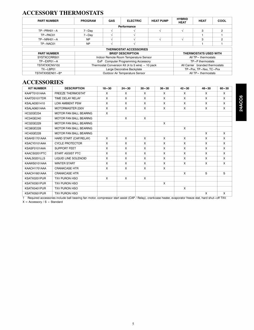
ACCESSORY THERMOSTATS
PART NUMBER PROGRAM GAS ELECTRIC HEAT PUMPHYBRIDHEAT
HEAT COOL
Performance
TP---PRH01---A 7---Day √ √ √ √ 3 2
TP---PAC01 7---Day √ √ 1 1
TP---NRH01---A NP √ √ √ √ 3 2
TP---NAC01 NP √ √ 1 1
THERMOSTAT ACCESSORIES
PART NUMBER BRIEF DESCRIPTION THERMOSTATS USED WITH
SYSTXCCRRS01 Indoor Remote Room Temperature Sensor All TP--- thermostats
TP---EXP01---A ExP� Computer Programming Accessory TP---P thermostats
TSTATXXCNV10‡ Thermostat Conversion Kit (4 to 5 wire) --- 10 pack All Carrier� branded thermostats
TX---LBP01 Large Decorative Backplate TP---Pxx, TP---Nxx, TC---Pxx
TSTATXXSEN01---B* Outdoor Air Temperature Sensor All TP--- thermostats
ACCESSORIESKIT NUMBER DESCRIPTION 18---30 24---30 30---30 36---30 42---30 48---30 60---30
KAAFT0101AAA FREEZE THERMOSTAT X X X X X X X
KAATD0101TDR TIME DELAY RELAY X X X X X X X
KSALA0301410 LOW AMBIENT PSW X X X X X X X
KSALA0601AAA MOTORMASTER 230V X X X X X X X
HC32GE234 MOTOR FAN BALL BEARING X
HC34GE240 MOTOR FAN BALL BEARING X X
HC32GE229 MOTOR FAN BALL BEARING X
HC38GE228 MOTOR FAN BALL BEARING X
HC40GE228 MOTOR FAN BALL BEARING X X
KSAHS1701AAA HARD START (CAP/RELAY) X X X X X X X
KSACY0101AAA CYCLE PROTECTOR X X X X X X X
KSASF0101AAA SUPPORT FEET X X X X X X X
KAACS0201PTC START ASSIST PTC X X X X X X X
KAALS0201LLS LIQUID LINE SOLENOID X X X X X X X
KAAWS0101AAA WINTER START X X X X X X X
KAACH1701AAA CRANKCASE HTR X X X X
KAACH1601AAA CRANKCASE HTR X S S
KSATX0201PUR TXV PURON HSO X X X
KSATX0301PUR TXV PURON HSO X
KSATX0401PUR TXV PURON HSO X
KSATX0501PUR TXV PURON HSO X X
{ Required accessories include ball bearing fan motor, compressor start assist (CAP / Relay), crankcase heater, evaporator freeze stat, hard shut---off TXV.
X = Accessory / S --- Standard
24ACC6

6
ACCESSORY USAGE GUIDELINE
ACCESSORY
REQUIRED FOR LOW---AMBI-ENT COOLING APPLICATIONS
(Below 55°F/12.8_C)
REQUIRED FOR LONGLINE
APPLICATIONS*(Over 80 ft./24.38 m)
REQUIRED FORSEA COAST
APPLICATIONS(Within 2 miles/3.22 km)
Ball Bearing Fan Motor Yes{ No No
Compressor Start Assist Capacitor and Relay Yes Yes No
Crankcase Heater Yes Yes No
Evaporator Freeze Thermostat Yes No No
Hard Shut---Off TXV Yes Yes Yes
Liquid Line Solenoid Valve No No No
Motor Master® Control orLow---ambient Pressure Switch
Yes No No
Support Feet Recommended No Recommended
Winter Start Control Yes No No
* For tubing line sets between 80 and 200 ft. (24.38 and 60.96 m) and/or 20 ft. (6.09 m) vertical differential, refer to Residential Split ---System LonglineApplication Guideline.
{ Required for Low---Ambient Controller (full modulation feature) MotorMasterr Control.
Accessory Description and Usage (Listed Alphabetically)1. Ball--Bearing Fan Motor
A fan motor with ball bearings which permits speed reductionwhile maintaining bearing lubrication.
Usage Guideline:
Required on all units when MotorMasterr is used.
2. Compressor Start Assist -- Capacitor and Relay
Start capacitor and relay gives a ”hard” boost to compressormotor at each start up.
Usage Guideline:
Required for reciprocating compressors in thefollowing applications:
Long line
Low ambient cooling
Hard shut off expansion valve on indoor coil
Liquid line solenoid on indoor coil
Required for single--phase scroll compressors in the
following applications:
Long line
Low ambient cooling
Suggested for all compressors in areas with a history of
low voltage problems.
3. Compressor Start Assist — PTC Type
Solid state electrical device which gives a ”soft” boost to the
compressor at each start--up.
Usage Guideline:
Suggested in installations with marginal power supply.
4. Crankcase Heater
An electric resistance heater which mounts to the base of the
compressor to keep the lubricant warm during off cycles.Improves compressor lubrication on restart and minimizes the
chance of liquid slugging.
Usage Guideline:
Required in low ambient cooling applications.
Required in long line applications.
Suggested in all commercial applications.
5. Cycle Protector
The cycle protector is designed to prevent compressor shortcycling. This control provides an approximate 5--minute delay
after power to the compressor has been interrupted for anyreason, including power outage, protector control trip, thermostatjiggling, or normal cycling.
6. Evaporator Freeze Thermostat
An SPST temperature--actuated switch that stops unit operation
when evaporator reaches freeze--up conditions.
Usage Guideline:
Required when low ambient kit has been added.
7. Low--Ambient Pressure Switch Kit
A long life pressure switch which is mounted to outdoor unit
service valve. It is designed to cycle the outdoor fan motor inorder to maintain head pressure within normal operating limits(approximately 100 psig to 225 psig). The control will maintain
working head pressure at low--ambient temperatures down to 0_F(--18_C) when properly installed.
Usage Guideline:
A Low--Ambient Pressure Switch or MotorMasterr
Low--Ambient Controller must be used when cooling operation isused at outdoor temperatures below 55_F (12.8_C).
8. MotorMasterr Low--Ambient Controller
A fan--speed control device activated by a temperature sensor,designed to control condenser fan motor speed in response to the
saturated, condensing temperature during operation in coolingmode only. For outdoor temperatures down to --20_F (--28.9_C),it maintains condensing temperature at 100_F ±10_F (37.8_C ±5.5_C).
Usage Guideline:
A MotorMasterr Low Ambient Controller orLow--Ambient Pressure Switch must be used whencooling operation is used at outdoor temperatures
below 55_F (12.8_C).
Suggested for all commercial applications.
9. Outdoor Air Temperature Sensor
Designed for use with Carrier Thermostats listed in this
publication. This device enables the thermostat to display theoutdoor temperature. This device also
is required to enable special thermostat features such as auxiliary
heat lock out.
Usage Guideline:
Suggested for all Carrier thermostats listed in thispublication.
24ACC6

7
Accessory Description and Usage (Listed Alphabetically) (Continued)10. Support Feet
Four stick--on plastic feet that raise the unit 4 in. (101.6 mm)above the mounting pad. This allows sand, dirt, and other debris
to be flushed from the unit base, minimizing corrosion.
Usage Guideline:
Suggested in the following applications:
Coastal installations.
Windy areas or where debris is normally circulating.
Rooftop installations.
For improved sound ratings.
11. Thermostatic Expansion Valve (TXV)
A modulating flow--control valve which meters refrigerant liquidflow rate into the evaporator in response to the superheat of the
refrigerant gas leaving the evaporator.
Kit includes valve, adapter tubes, and external equalizer tube.Hard shut off types are available.
NOTE: When using a hard shut off TXV with single phase
reciprocating compressors, a Compressor Start Assist Capacitor
and Relay is required.
Usage Guideline:
Required to achieve AHRI ratings in certain equipment
combinations. Refer to combination ratings.
Hard shut off TXV or LLS required in air conditionerlong line applications.
Required for use on all zoning systems.
12. Time--Delay Relay
An SPST delay relay which briefly continues operation of indoorblower motor to provide additional cooling after the compressor
cycles off.
NOTE: Most indoor unit controls include this feature. For those
that do not, use the guideline below.
Usage Guideline:
For improved efficiency ratings for certaincombinations of indoor and outdoor units. Refer toAHRI Unitary Directory.
13. Winter Start Control
This control is designed to alleviate nuisance opening of the
low--pressure switch by bypassing it for the first 3 minutes ofoperation.
24ACC6

8
ELECTRICAL DATA
UNIT SIZE V/PH
OPER VOLTS* COMPR FAN
MCA
MINWIRESIZE{60° C
MINWIRESIZE{75° C
MAXLENGTHft. (m)}60° C
MAXLENGTHft. (m)}75° C
MAXFUSE**or CKTBRKAMPS
MAX MIN LRA RLA FLA
18---30
208/230/1---60 253 197
48.0 9.0 0.50 11.8 14 14 67 (20.4) 64 (19.5) 20
24---30 58.3 13.5 0.70 17.6 14 14 46 (14.0) 43 (13..1) 25
30---30 64.0 12.8 0.70 16.7 14 14 44 (13.4) 41 (12.5) 25
36---30 77.0 14.1 0.50 18.1 12 12 57 (17.4) 54 (16.5) 30
42---30 112.0 17.9 1.20 23.6 10 10 85 (25.9) 81 (24.7) 40
48---30 109.0 19.9 1.20 26.1 10 10 70 (21.3) 67 (20.4) 40
60---30 135.0 21.4 1.20 28.0 8 10 91 (27.7) 56 (17.1) 40
* Permissible limits of the voltage range at which the unit will operate satisfactorily
{ If wire is applied at ambient greater than 30_C, consult table 310---16 of the NEC (NFPA 70). The ampacity of non---metallic---sheathed cable (NM), tradename ROMEX, shall be that of 60_C conditions, per the NEC (NFPA 70) Article 336---26. If other than uncoated (no---plated), 60 or 75_C insulation, copperwire (solid wire for 10 AWG or smaller, stranded wire for larger than 10 AWG) is used, consult applicable tables of the NEC (NFPA 70).
} Length shown is as measured one way along wire path between unit and service panel for voltage drop not to exceed 2%.
** Time---Delay fuse.
FLA --- Full Load Amps
LRA --- Locked Rotor Amps
MCA --- Minimum Circuit Amps
RLA --- Rated Load Amps
NOTE: Control circuit is 24---V on all units and requires external power source. Copper wire must be used from service disconnect to unit.All motors/compressors contain internal overload protection.
Complies with 2010 requirements of ASHRAE Standards 90.1
A--WEIGHTED SOUND POWER LEVEL (dBA)Unit Size ---
Voltage, SeriesStandard
Rating (dBA)TYPICAL OCTAVE BAND SPECTRUM (dBA without tone adjustment)
125 250 500 1000 2000 4000 8000
18---30 73 49.5 58.5 64.5 69.0 63.0 59.5 52.4
24---30 74 54.5 62.0 67.0 71.5 66.0 62.0 53.0
30---30 74 56.0 62.5 66.0 68.5 64.5 61.0 53.5
36---30 72 52.0 61.0 64.0 66.0 61.0 58.5 51.5
42---30 74 56.5 61.5 65.0 66.5 63.5 61.0 56.5
48---30 73 58.0 61.0 65.0 66.0 62.0 58.0 51.0
60---30 74 56.5 62.5 66.5 68.0 63.0 59.5 51.5
NOTE: Tested in accordance with AHRI Standard 270---08 (not listed in AHRI).
CHARGING SUBCOOLING (TXV--TYPE EXPANSION DEVICE)UNIT SIZE---VOLTAGE, SERIES REQUIRED SUBCOOLING _F (_C)
18---30 10 (5.6)
24---30 10 (5.6)
30---30 10 (5.6)
36---30 10 (5.6)
42---30 9 (5.0)
48---30 10 (5.6)
60---30 9 (5.0)
24ACC6

9
DIM
ENSIONS--ENGLISH
3"
K
5/16"
L
N
M
E
F
G
C31/2"
17/8"
P
A
B
208-230-1-60
230-1-60
208/230-3-60
460-3-60
UNIT
SERIES
ELECTRICAL
CHARACTERISTICSA
BC
DE
FG
KL
MN
POPERATING
WEIGHT(lbs)SHIPPING
WEIGHT(lbs)
SHIPPING
DIMENSIONS(LxWxH)
24ACC618
0X
OO
O253/4"
2811/16"
33/4"
3/4"
47/16"
211/4"
713/16"
213/16"
1/2"
131/4"
133/4"
123/4"
136
163
267/8"X301/16"X329/16"
24ACC624
0X
OO
O313/16"
285/16"
33/4"
3/4"
69/16"
2411/16"
91/8"
213/16"
1/2"
155/8"
151/2"
14"
163
198
323/8"X351/2"X329/16"
24ACC630
0X
OO
O313/16"
325/16"
33/4"
3/4"
69/16"
2411/16"
91/8"
213/16"
1/2"
161/2"
15"
143/4"
167
204
323/8"X351/2"X3515/16"
24ACC636
0X
OO
O35"
285/16"
37/8"
7/8"
69/16"
287/16"
91/8"
215/16"
5/8"
181/4"
167/8"
14"
180
219
361/8"X395/16"X329/16"
24ACC642
0X
OO
O35"
391/8"
37/8"
7/8"
69/16"
287/16"
91/8"
215/16"
5/8"
18"
16"
171/2"
234
281
361/8"X395/16"X423/4"
24ACC648
0X
OO
O35"
325/16"
37/8"
7/8"
69/16"
287/16"
91/8"
215/16"
5/8"
17"
171/2"
14"
248
291
361/8"X395/16"X3515/16"
24ACC660
0X
OO
O35"
4515/16"
37/8"
7/8"
69/16"
287/16"
91/8"
215/16"
5/8"
177/8"
185/8"
201/4"
337
372
361/8"X395/16"X499/16"
UNITSIZE
MINIMUM
MOUNTINGPAD
DIMENSIONS
18
26"X26"
24,30
311/2"X311/2"
36THRU60
35"X35"
AIR
DISCHARGE
AIRIN
AIRIN
AIRIN
AIRIN
3/8"TIEDOWNKNOCKOUTS
(2)PLACES
X=YES
O=NO
NOTES:
1.ALLOW30"CLEARANCETOSERVICESIDEOFUNIT,
48"ABOVEUNIT,6"ONONESIDE,12"ONREMAININGSIDE,
AND24"BETWEENUNITSFORPROPERAIRFLOW.
2.MINIMUMOUTDOOROPERATINGAMBIENTINCOOLING
MODEIS55
F,MAX.125
3.SERIESDESIGNATIONISTHE13THPOSITIONOFTHE
UNITMODELNUMBER.
4.CENTEROFGRAVITY
.
5.ALLDIMENSIONSAREIN"INCHES"UNLESSNOTED.
AIRDISCHARGE
SQ.
VAPORLINECONN.
FIELDCONTROL
SUPPLYCONN.
7/8"HOLE
FIELDPOWERSUPPLYCONN.
7/8"HOLEWITH
11/8"KNOCKOUT
D
24ACC6

10
DIM
ENSIONS--SI
76.2
K
8.0
L
N
M
E
F
G
A
P
47.6
C88.9
B
208-230-1-60
230-1-60
208/230-3-60
460-3-60
UNIT
SERIESELECTRICAL
CHARACTERISTICSA
BC
DE
FG
KL
MN
POPERATING
WEIGHT(Kgs)SHIPPING
WEIGHT(Kgs)
SHIPPING
DIMENSIONS(LxWxH)
24ACC618
0X
OO
O654.0
728.7
95.2
19.0
112.7
539.8
198.4
71.4
12.7
336.6
349.3
323.9
61.7
73.9
682.6X763.6X827.1
24ACC624
0X
OO
O792.2
719.2
95.2
19.0
166.7
627.1
231.8
71.4
12.7
396.9
393.7
355.6
73.9
89.8
822.3X901.7X827.1
24ACC630
0X
OO
O792.2
820.8
95.2
19.0
166.7
627.1
231.8
71.4
12.7
419.1
381.0
374.7
75.7
92.5
822.3X901.7X912.8
24ACC636
0X
OO
O889.0
719.2
98.6
22.2
166.7
722.3
231.8
74.6
15.9
463.6
428.6
355.6
81.6
99.3
917.6X998.6X827.1
24ACC642
0X
OO
O889.0
993.8
98.6
22.2
166.7
722.3
231.8
74.6
15.9
457.2
406.4
444.5
106.1
127.5
917.6X998.6X1085.8
24ACC648
0X
OO
O889.0
820.8
98.6
22.2
166.7
722.3
231.8
74.6
15.9
431.8
444.5
355.6
112.5
132.0
917.6X998.6X912.8
24ACC660
0X
OO
O889.0
1166.8
98.6
22.2
166.7
722.3
231.8
74.6
15.9
454.0
473.1
514.4
152.9
168.7
917.6X998.6X1173.2
UNITSIZE
MINIMUM
MOUNTINGPAD
DIMENSIONS
18
660.4X660.4
24,30
800.1X800.1
36THRU60
889.0X889.0
AIR
DISCHARGE
AIRIN
AIRIN
AIRIN
AIRIN
9.53TIEDOWNKNOCKOUTS
(2)PLACES
X=YES
O=NO
NOTES:
1.ALLOW762.0CLEARANCETOSERVICESIDEOFUNIT,
1219.2ABOVEUNIT,152.4ONONESIDE,304.8ONREMAININGSIDE,
AND609.6BETWEENUNITSFORPROPERAIRFLOW.
2.MINIMUMOUTDOOROPERATINGAMBIENTINCOOLING
MODEIS13
C,MAX.52
3.SERIESDESIGNATIONISTHE10THPOSITIONOFTHE
UNITMODELNUMBER.
4.CENTEROFGRAVITY
.
5.ALLDIMENSIONSAREIN"MM"UNLESSNOTED.
AIRDISCHARGE
SQ.
VAPORLINECONN.
FIELDCONTROL
SUPPLYCONN.
22.23HOLE
FIELDPOWERSUPPLYCONN.
22.23HOLEWITH
28.58KNOCKOUT
D
24ACC6

11
CLEARANCES
Cle
ara
nces (
vari
ou
s e
xam
ple
s)
Wa
ll
Wall
Wa
ll
Wall2
4”
Se
rvic
e
6”
(152.4
mm
)
24
”
(609.6
)
Serv
ice
24
”
(609.6
)
Serv
ice
24
”
(609.6
)
Serv
ice
24
”
(609.6
)
Serv
ice
24
”
(609.6
)
24
”
(609.6
)
24
”
(609.6
)
12
”
(304.8
)
12
”
(304.8
)
12
”
(304.8
)
12
”
(304.8
)
6”
(15
2.4
)
No
te:
Nu
mb
ers
in
( )
= m
m
IMPORTANT:When
installingmultipleunitsinan
alcove,roofwell,orpartiallyenclosedarea,ensurethereisadequateventilationtopreventre--circulationofdischargeair.
24ACC6

12
TESTED AHRI COMBINATION RATINGS*
NOTE: Ratings contained in this document are subject to change at any time.
For AHRI ratings certificates, please refer to the AHRI directory www.ahridirectory.org
Additional ratings and system combinations can be accessed via the Carrier database at:
http://cactaxcredits.info/carrier-ratings/ac_ratings_srch.php
Equipment performance calculator can be accessed at: http://rpmob.wrightsoft.com/
Model Number Indoor Model Furnace Model Capacity EER SEER
24ACC618A**30 CNPV*1917A**+TDR 18,000 12.0 14.5
24ACC624A**30 CNPV*3117A**+TDR 23,600 12.0 14.5
24ACC630A**30 CNPV*3117A**+TDR 28,600 12.0 14.5
24ACC636A**30 CNPV*3717A**+TDR 34,400 12.0 14.5
24ACC642A**30 CNPV*4324A**+TDR 41,500 12.0 14.5
24ACC648A**30 CNPV*6124A**+TDR 46,500 12.5 14.5
24ACC660A**30 CNPV*6124A**+TDR 55,000 12.5 14.5
* AHRI = Air Conditioning, Heating & Refrigeration InstituteEER — Energy Efficiency Ratio --- ’A’ conditions --- 80_F (26.6_C) indoor db/67_F (19.4_C) indoor wb & 95_F (35_C) outdoor wb.SEER — Seasonal Energy Efficiency RatioTDR — Time---Delay Relay. In most cases, only one method should be used to achieve TDR function. Using more than one method in a system may cause degradation in
performance. Use either the accessory Time---Delay Relay, KAATD0101TDR, or a furnace equipped with TDR. Most Carrier furnaces are equipped with TDR.NOTES:
1. Ratings are net values reflecting the effects of circulating fan motor heat. Supplemental electric heat is not included.
2. Tested outdoor/indoor combinations have been tested in accordance with DOE test procedures for central air conditioners. Ratings for othercombinations are determined under DOE computer simulation procedures.
3. Determine actual CFM values obtainable for your system by referring to fan performance data in fan coil or furnace coil literature.
4. Do not apply with capillary tube coils as performance and reliability are significantly affected.
24ACC6

13
DETAILEDCOOLINGCAPACITIES#
EVAPORATORAIR
CONDENSERENTERINGAIR
TEMPERATURES
°F(°C)
75(23.9)
85(29.4)
95(35)
105(40.6)
115(46.1)
125(51.7)
CFM
EWB
°F(°C)
CapacityMBtuh
Total
System
KW**
CapacityMBtuh
Total
System
KW**
CapacityMBtuh
Total
System
KW**
CapacityMBtuh
Total
System
KW**
CapacityMBtuh
Total
System
KW**
CapacityMBtuh
Total
System
KW**
Total
Sens‡
Total
Sens‡
Total
Sens‡
Total
Sens‡
Total
Sens‡
Total
Sens‡
24ACC618A**30OutdoorSectionWithCNPV*1917A**IndoorSection
525
72(22.2)
21.52
10.39
1.18
20.55
10.05
1.32
19.48
9.68
1.48
18.35
9.29
1.65
17.15
8.88
1.84
15.88
8.46
2.06
67(19.4)
19.59
12.69
1.18
18.66
12.32
1.32
17.68
11.95
1.47
16.64
11.56
1.64
15.54
11.14
1.83
14.37
10.72
2.05
63(17.2)††
18.14
12.20
1.18
17.28
11.84
1.32
16.37
11.47
1.47
15.40
11.07
1.63
14.37
10.66
1.82
13.27
10.22
2.04
62(16.7)
17.80
14.92
1.18
16.97
14.56
1.31
16.08
14.18
1.47
15.17
13.78
1.63
14.30
14.30
1.82
13.42
13.42
2.04
57(13.9)
17.19
17.19
1.18
16.54
16.54
1.31
15.84
15.84
1.46
15.09
15.09
1.63
14.27
14.27
1.82
13.40
13.40
2.04
600
72(22.2)
21.94
10.93
1.21
20.92
10.58
1.35
19.82
10.21
1.51
18.63
9.81
1.68
17.39
9.40
1.87
16.07
8.97
2.09
67(19.4)
19.99
13.55
1.20
19.03
13.19
1.35
18.00
12.80
1.50
16.92
12.40
1.67
15.78
11.98
1.86
14.57
11.54
2.08
63(17.2)††
18.55
13.02
1.20
17.64
12.65
1.34
16.68
12.26
1.49
15.68
11.86
1.66
14.60
11.44
1.85
13.47
10.99
2.07
62(16.7)
18.25
16.11
1.20
17.39
15.72
1.34
16.55
16.55
1.49
15.74
15.74
1.66
14.87
14.87
1.85
13.93
13.93
2.07
57(13.9)
17.99
17.99
1.20
17.28
17.28
1.34
16.53
16.53
1.49
15.72
15.72
1.66
14.85
14.85
1.85
13.91
13.91
2.07
675
72(22.2)
22.24
11.45
1.23
21.19
11.09
1.38
20.06
10.72
1.54
18.83
10.32
1.71
17.55
9.90
1.90
16.20
9.47
2.12
67(19.4)
20.29
14.38
1.23
19.30
14.01
1.37
18.24
13.62
1.53
17.13
13.22
1.70
15.95
12.79
1.89
14.72
12.34
2.10
63(17.2)††
18.85
13.79
1.23
17.91
13.42
1.37
16.92
13.03
1.52
15.88
12.61
1.69
14.78
12.18
1.88
13.63
11.73
2.10
62(16.7)
18.68
18.68
1.23
17.93
17.93
1.37
17.12
17.12
1.52
16.26
16.26
1.69
15.33
15.33
1.88
14.35
14.35
2.10
57(13.9)
18.66
18.66
1.23
17.90
17.90
1.37
17.09
17.09
1.52
16.24
16.24
1.69
15.31
15.31
1.88
14.33
14.33
2.10
EVAPORATORAIR
CONDENSERENTERINGAIR
TEMPERATURES
°F(°C)
75(23.9)
85(29.4)
95(35)
105(40.6)
115(46.1)
125(51.7)
CFM
EWB
°F(°C)
CapacityMBtuh
Total
System
KW**
CapacityMBtuh
Total
System
KW**
CapacityMBtuh
Total
System
KW**
CapacityMBtuh
Total
System
KW**
CapacityMBtuh
Total
System
KW**
CapacityMBtuh
Total
System
KW**
Total
Sens‡
Total
Sens‡
Total
Sens‡
Total
Sens‡
Total
Sens‡
Total
Sens‡
24ACC624A**30OutdoorSectionWithCNPV*3117A**IndoorSection
700
72(22.2)
28.21
13.70
1.55
26.92
13.25
1.74
25.54
12.78
1.94
24.09
12.29
2.16
22.56
11.77
2.41
20.94
11.24
2.68
67(19.4)
25.63
16.78
1.55
24.44
16.32
1.73
23.19
15.85
1.93
21.87
15.36
2.15
20.47
14.84
2.39
18.98
14.29
2.67
63(17.2)††
23.72
16.13
1.55
22.62
15.67
1.73
21.46
15.20
1.92
20.22
14.70
2.14
18.91
14.18
2.38
17.52
13.62
2.67
62(16.7)
23.32
19.80
1.55
22.25
19.34
1.73
21.14
18.86
1.92
20.00
19.96
2.14
18.95
18.95
2.38
17.82
17.82
2.67
57(13.9)
22.68
22.68
1.55
21.84
21.84
1.73
20.93
20.93
1.92
19.96
19.96
2.14
18.92
18.92
2.38
17.79
17.79
2.67
800
72(22.2)
28.72
14.43
1.58
27.38
13.97
1.77
25.95
13.49
1.98
24.44
12.99
2.20
22.85
12.47
2.44
21.17
11.93
2.72
67(19.4)
26.16
17.95
1.58
24.91
17.49
1.77
23.60
17.00
1.97
22.22
16.49
2.19
20.76
15.96
2.43
19.23
15.41
2.71
63(17.2)††
24.23
17.22
1.58
23.08
16.75
1.77
21.86
16.27
1.96
20.58
15.76
2.18
19.21
15.22
2.42
17.78
14.66
2.70
62(16.7)
23.91
21.38
1.58
22.85
22.74
1.77
21.85
21.85
1.96
20.81
20.81
2.18
19.69
19.69
2.42
18.49
18.49
2.71
57(13.9)
23.70
23.70
1.58
22.79
22.79
1.76
21.82
21.82
1.96
20.78
20.78
2.18
19.66
19.66
2.43
18.46
18.46
2.71
900
72(22.2)
29.09
15.12
1.62
27.72
14.67
1.81
26.23
14.18
2.02
24.68
13.67
2.24
23.05
13.15
2.48
21.32
12.60
2.76
67(19.4)
26.54
19.08
1.62
25.25
18.60
1.81
23.90
18.11
2.01
22.48
17.59
2.22
20.98
17.05
2.47
19.42
16.48
2.75
63(17.2)††
24.61
18.27
1.62
23.42
17.79
1.80
22.16
17.30
2.00
20.84
16.78
2.22
19.45
16.23
2.46
17.98
15.65
2.74
62(16.7)
24.60
24.60
1.62
23.62
23.62
1.80
22.58
22.58
2.00
21.48
21.48
2.22
20.29
20.29
2.47
19.02
19.02
2.75
57(13.9)
24.56
24.56
1.62
23.59
23.59
1.80
22.55
22.55
2.00
21.45
21.45
2.22
20.27
20.27
2.47
18.99
18.99
2.75
Seenotesonpg.16
24ACC6

14
DETAILEDCOOLINGCAPACITIES#(CONT.)
EVAPORATORAIR
CONDENSERENTERINGAIR
TEMPERATURES
°F(°C)
75(23.9)
85(29.4)
95(35)
105(40.6)
115(46.1)
125(51.7)
CFM
EWB
°F(°C)
CapacityMBtuh
Total
System
KW**
CapacityMBtuh
Total
System
KW**
CapacityMBtuh
Total
System
KW**
CapacityMBtuh
Total
System
KW**
CapacityMBtuh
Total
System
KW**
CapacityMBtuh
Total
System
KW**
Total
Sens‡
Total
Sens‡
Total
Sens‡
Total
Sens‡
Total
Sens‡
Total
Sens‡
24ACC630A**30OutdoorSectionWithCNPV*3117A**IndoorSection
875
72(22.2)
34.09
17.01
1.91
32.58
16.48
2.11
31.00
15.93
2.33
29.32
15.36
2.59
27.51
14.75
2.88
25.53
14.09
3.22
67(19.4)
30.99
20.96
1.92
29.61
20.43
2.12
28.16
19.88
2.34
26.61
19.29
2.59
24.93
18.66
2.88
23.10
17.99
3.22
63(17.2)††
28.76
20.15
1.93
27.47
19.62
2.12
26.11
19.06
2.34
24.65
18.46
2.59
23.07
17.83
2.88
21.33
17.13
3.22
62(16.7)
28.31
24.86
1.93
27.08
24.31
2.12
25.80
23.72
2.34
24.56
24.56
2.59
23.28
23.28
2.88
21.87
21.87
3.21
57(13.9)
27.76
27.76
1.93
26.76
26.76
2.12
25.69
25.69
2.34
24.52
24.52
2.59
23.25
23.25
2.88
21.83
21.83
3.21
1000
72(22.2)
34.67
17.91
1.96
33.09
17.37
2.15
31.45
16.82
2.38
29.71
16.24
2.63
27.83
15.62
2.93
25.79
14.95
3.26
67(19.4)
31.55
22.41
1.97
30.10
21.86
2.16
28.60
21.30
2.38
27.00
20.71
2.64
25.27
20.07
2.93
23.39
19.37
3.26
63(17.2)††
29.30
21.50
1.97
27.95
20.95
2.17
26.55
20.38
2.39
25.04
19.78
2.64
23.40
19.12
2.93
21.63
18.42
3.26
62(16.7)
29.03
28.77
1.97
27.89
27.89
2.16
26.74
26.74
2.39
25.50
25.50
2.64
24.14
24.14
2.93
22.64
22.64
3.26
57(13.9)
28.93
28.93
1.97
27.84
27.84
2.16
26.70
26.70
2.39
25.46
25.46
2.64
24.11
24.11
2.93
22.61
22.61
3.26
1125
72(22.2)
35.09
18.77
2.00
33.45
18.22
2.20
31.76
17.66
2.42
29.97
17.07
2.68
28.04
16.45
2.97
25.96
15.78
3.31
67(19.4)
31.96
23.80
2.01
30.47
23.24
2.21
28.93
22.67
2.43
27.29
22.06
2.68
25.52
21.41
2.97
23.62
20.69
3.31
63(17.2)††
29.70
22.78
2.02
28.32
22.23
2.21
26.87
21.65
2.43
25.32
21.03
2.69
23.66
20.36
2.98
21.87
19.61
3.31
62(16.7)
29.93
29.93
2.02
28.78
28.78
2.21
27.57
27.57
2.43
26.26
26.26
2.68
24.83
24.83
2.97
23.26
23.26
3.31
57(13.9)
29.89
29.89
2.02
28.74
28.74
2.21
27.53
27.53
2.43
26.22
26.22
2.68
24.80
24.80
2.97
23.23
23.23
3.31
EVAPORATORAIR
CONDENSERENTERINGAIR
TEMPERATURES
°F(°C)
75(23.9)
85(29.4)
95(35)
105(40.6)
115(46.1)
125(51.7)
CFM
EWB
°F(°C)
CapacityMBtuh
Total
System
KW**
CapacityMBtuh
Total
System
KW**
CapacityMBtuh
Total
System
KW**
CapacityMBtuh
Total
System
KW**
CapacityMBtuh
Total
System
KW**
CapacityMBtuh
Total
System
KW**
Total
Sens‡
Total
Sens‡
Total
Sens‡
Total
Sens‡
Total
Sens‡
Total
Sens‡
24ACC636A**30OutdoorSectionWithCNPV*3717A**IndoorSection
1050
72(22.2)
41.06
20.32
2.39
39.22
19.68
2.65
37.27
19.01
2.95
35.20
18.31
3.28
33.01
17.57
3.66
30.65
16.79
4.11
67(19.4)
37.33
25.02
2.37
35.65
24.38
2.63
33.87
23.70
2.93
31.96
22.99
3.26
29.95
22.24
3.65
27.79
21.45
4.09
63(17.2)††
34.65
24.06
2.36
33.08
23.41
2.62
31.40
22.73
2.92
29.62
22.01
3.25
27.73
21.26
3.64
25.71
20.45
4.09
62(16.7)
34.09
29.67
2.36
32.58
29.00
2.62
31.00
28.29
2.91
29.47
29.47
3.25
27.95
27.95
3.64
26.29
26.29
4.09
57(13.9)
33.38
33.38
2.35
32.16
32.16
2.62
30.85
30.85
2.91
29.43
29.43
3.25
27.91
27.91
3.64
26.25
26.25
4.09
1200
72(22.2)
41.77
21.40
2.45
39.84
20.74
2.72
37.82
20.07
3.01
35.67
19.35
3.35
33.39
18.60
3.73
30.96
17.82
4.17
67(19.4)
38.02
26.75
2.43
36.25
26.09
2.70
34.40
25.40
2.99
32.44
24.67
3.32
30.35
23.91
3.71
28.13
23.10
4.15
63(17.2)††
35.31
25.67
2.42
33.66
25.01
2.69
31.93
24.31
2.98
30.09
23.58
3.31
28.13
22.80
3.70
26.05
21.98
4.15
62(16.7)
34.94
31.96
2.42
33.53
33.53
2.69
32.12
32.12
2.98
30.60
30.60
3.32
28.97
28.97
3.70
27.21
27.21
4.15
57(13.9)
34.80
34.80
2.42
33.47
33.47
2.68
32.07
32.07
2.98
30.55
30.55
3.32
28.93
28.93
3.70
27.17
27.17
4.15
1350
72(22.2)
42.28
22.42
2.52
40.29
21.76
2.78
38.19
21.07
3.08
35.98
20.35
3.41
33.65
19.59
3.79
31.16
18.80
4.23
67(19.4)
38.51
28.41
2.50
36.70
27.73
2.76
34.80
27.03
3.05
32.78
26.29
3.39
30.65
25.51
3.77
28.39
24.66
4.22
63(17.2)††
35.80
27.21
2.48
34.11
26.53
2.75
32.32
25.82
3.04
30.43
25.07
3.38
28.44
24.28
3.76
26.32
23.41
4.21
62(16.7)
36.01
36.01
2.48
34.61
34.61
2.75
33.12
33.12
3.05
31.51
31.51
3.38
29.80
29.80
3.77
27.94
27.94
4.21
57(13.9)
35.96
35.96
2.48
34.56
34.56
2.75
33.08
33.08
3.04
31.47
31.47
3.38
29.76
29.76
3.77
27.91
27.91
4.21
Seenotesonpg.16
24ACC6

15
DETAILEDCOOLINGCAPACITIES#(CONT.)
EVAPORATORAIR
CONDENSERENTERINGAIR
TEMPERATURES
°F(°C)
75(23.9)
85(29.4)
95(35)
105(40.6)
115(46.1)
125(51.7)
CFM
EWB
°F(°C)
CapacityMBtuh
Total
System
KW**
CapacityMBtuh
Total
System
KW**
CapacityMBtuh
Total
System
KW**
CapacityMBtuh
Total
System
KW**
CapacityMBtuh
Total
System
KW**
CapacityMBtuh
Total
System
KW**
Total
Sens‡
Total
Sens‡
Total
Sens‡
Total
Sens‡
Total
Sens‡
Total
Sens‡
24ACC642A**30OutdoorSectionWithCNPV*4324A**IndoorSection
1225
72(22.2)
49.58
24.85
2.77
47.31
24.05
3.07
44.88
23.20
3.42
42.30
22.31
3.80
39.58
21.39
4.23
36.71
20.43
4.70
67(19.4)
45.17
30.63
2.75
43.10
29.82
3.05
40.90
28.98
3.38
38.55
28.08
3.76
36.07
27.15
4.19
33.47
26.18
4.66
63(17.2)††
41.97
29.47
2.74
40.06
28.67
3.03
38.02
27.83
3.36
35.83
26.93
3.74
33.53
26.00
4.17
31.10
25.02
4.64
62(16.7)
41.32
36.33
2.74
39.49
35.51
3.03
37.56
34.61
3.36
35.65
35.65
3.74
33.78
33.78
4.17
31.76
31.76
4.64
57(13.9)
40.45
40.45
2.73
38.96
38.96
3.03
37.34
37.34
3.36
35.60
35.60
3.74
33.73
33.73
4.17
31.72
31.72
4.64
1400
72(22.2)
50.40
26.14
2.85
48.02
25.31
3.15
45.48
24.45
3.49
42.82
23.55
3.87
39.99
22.61
4.30
37.02
21.63
4.77
67(19.4)
45.95
32.69
2.82
43.80
31.87
3.12
41.50
31.00
3.46
39.07
30.09
3.84
36.51
29.14
4.26
33.83
28.13
4.74
63(17.2)††
42.74
31.39
2.81
40.75
30.58
3.10
38.61
29.71
3.44
36.36
28.80
3.82
33.97
27.84
4.24
31.47
26.83
4.71
62(16.7)
42.31
39.06
2.81
40.55
40.55
3.10
38.82
38.82
3.44
36.94
36.94
3.82
34.93
34.93
4.25
32.78
32.78
4.72
57(13.9)
42.10
42.10
2.81
40.50
40.50
3.10
38.76
38.76
3.44
36.89
36.89
3.82
34.89
34.89
4.25
32.74
32.74
4.72
1575
72(22.2)
50.98
27.35
2.92
48.52
26.51
3.22
45.91
25.64
3.56
43.16
24.73
3.95
40.25
23.78
4.37
37.22
22.79
4.85
67(19.4)
46.53
34.66
2.90
44.31
33.82
3.19
41.95
32.94
3.53
39.45
32.01
3.91
36.83
31.03
4.34
34.11
29.99
4.81
63(17.2)††
43.31
33.22
2.88
41.25
32.39
3.17
39.06
31.51
3.51
36.74
30.57
3.89
34.30
29.58
4.31
31.77
28.52
4.78
62(16.7)
43.52
43.52
2.88
41.82
41.82
3.18
39.96
39.96
3.52
37.98
37.98
3.90
35.86
35.86
4.33
33.58
33.58
4.80
57(13.9)
43.46
43.46
2.88
41.76
41.76
3.18
39.91
39.91
3.52
37.93
37.93
3.90
35.81
35.81
4.33
33.55
33.55
4.80
EVAPORATORAIR
CONDENSERENTERINGAIR
TEMPERATURES
°F(°C)
75(23.9)
85(29.4)
95(35)
105(40.6)
115(46.1)
125(51.7)
CFM
EWB
°F(°C)
CapacityMBtuh
Total
System
KW**
CapacityMBtuh
Total
System
KW**
CapacityMBtuh
Total
System
KW**
CapacityMBtuh
Total
System
KW**
CapacityMBtuh
Total
System
KW**
CapacityMBtuh
Total
System
KW**
Total
Sens‡
Total
Sens‡
Total
Sens‡
Total
Sens‡
Total
Sens‡
Total
Sens‡
24ACC648A**30OutdoorSectionWithCNPV*6124A**IndoorSection
1400
72(22.2)
56.17
28.26
2.67
53.35
27.27
3.12
50.45
26.26
3.57
47.46
25.24
4.03
44.32
24.18
4.51
41.00
23.07
5.02
67(19.4)
50.88
34.78
2.84
48.38
33.81
3.25
45.79
32.82
3.66
43.11
31.80
4.09
40.30
30.75
4.55
37.32
29.64
5.04
63(17.2)††
47.10
33.38
2.95
44.81
32.43
3.33
42.44
31.45
3.72
39.99
30.45
4.13
37.39
29.40
4.57
34.65
28.30
5.05
62(16.7)
46.38
41.24
2.96
44.21
40.25
3.34
42.02
41.83
3.72
40.01
40.01
4.12
37.89
37.89
4.56
35.59
35.59
5.05
57(13.9)
45.57
45.57
2.98
43.79
43.79
3.35
41.92
41.92
3.72
39.95
39.95
4.13
37.83
37.83
4.56
35.54
35.54
5.05
1600
72(22.2)
57.16
29.78
2.70
54.20
28.77
3.16
51.18
27.74
3.62
48.04
26.69
4.09
44.79
25.61
4.58
41.35
24.49
5.10
67(19.4)
51.83
37.21
2.88
49.20
36.22
3.30
46.50
35.20
3.72
43.71
34.16
4.16
40.79
33.07
4.62
37.73
31.93
5.12
63(17.2)††
48.01
35.64
2.99
45.60
34.66
3.39
43.14
33.66
3.78
40.57
32.63
4.20
37.89
31.55
4.64
35.07
30.41
5.13
62(16.7)
47.62
47.39
3.00
45.65
45.65
3.38
43.62
43.62
3.77
41.49
41.49
4.18
39.20
39.20
4.63
36.74
36.74
5.12
57(13.9)
47.51
47.51
3.00
45.58
45.58
3.38
43.56
43.56
3.77
41.43
41.43
4.18
39.15
39.15
4.63
36.69
36.69
5.12
1800
72(22.2)
57.88
31.22
2.74
54.82
30.20
3.21
51.68
29.15
3.68
48.44
28.08
4.15
45.10
26.99
4.64
41.56
25.85
5.17
67(19.4)
52.53
39.54
2.92
49.82
38.53
3.35
47.03
37.48
3.78
44.15
36.41
4.22
41.17
35.29
4.69
38.05
34.08
5.19
63(17.2)††
48.69
37.80
3.04
46.20
36.80
3.44
43.65
35.77
3.85
41.02
34.70
4.27
38.28
33.58
4.71
35.42
32.36
5.20
62(16.7)
49.20
49.20
3.02
47.12
47.12
3.42
44.96
44.96
3.82
42.68
42.68
4.24
40.26
40.26
4.70
37.65
37.65
5.19
57(13.9)
49.13
49.13
3.03
47.06
47.06
3.42
44.90
44.90
3.82
42.63
42.63
4.24
40.21
40.21
4.70
37.61
37.61
5.19
Seenotesonpg.16
24ACC6

16
DETAILEDCOOLINGCAPACITIES#(CONT.)
EVAPORATORAIR
CONDENSERENTERINGAIR
TEMPERATURES
°F(°C)
75(23.9)
85(29.4)
95(35)
105(40.6)
115(46.1)
125(51.7)
CFM
EWB
°F(°C)
CapacityMBtuh
Total
System
KW**
CapacityMBtuh
Total
System
KW**
CapacityMBtuh
Total
System
KW**
CapacityMBtuh
Total
System
KW**
CapacityMBtuh
Total
System
KW**
CapacityMBtuh
Total
System
KW**
Total
Sens‡
Total
Sens‡
Total
Sens‡
Total
Sens‡
Total
Sens‡
Total
Sens‡
24ACC660A**30OutdoorSectionWithCNPV*6124A**+TDRIndoorSection
1750
72(22.2)
66.03
33.71
3.54
62.86
32.49
3.92
59.49
31.24
4.33
55.92
29.95
4.78
52.09
28.60
5.29
47.94
27.18
5.86
67(19.4)
60.16
42.01
3.52
57.34
40.81
3.90
54.33
39.55
4.30
51.12
38.25
4.75
47.67
36.88
5.26
43.93
35.42
5.83
63(17.2)††
55.92
40.36
3.52
53.34
39.17
3.88
50.59
37.93
4.28
47.64
36.64
4.73
44.45
35.28
5.23
41.00
33.82
5.81
62(16.7)
55.30
50.14
3.52
52.96
52.74
3.88
50.72
50.72
4.28
48.29
48.29
4.73
45.62
45.62
5.24
42.65
42.65
5.83
57(13.9)
54.87
54.87
3.51
52.85
52.85
3.88
50.64
50.64
4.28
48.23
48.23
4.73
45.56
45.56
5.24
42.60
42.60
5.83
2000
72(22.2)
66.94
35.49
3.63
63.63
34.26
4.01
60.13
32.98
4.43
56.41
31.66
4.88
52.46
30.30
5.39
48.19
28.86
5.96
67(19.4)
61.07
44.91
3.62
58.11
43.67
3.99
55.00
42.39
4.40
51.67
41.04
4.85
48.13
39.62
5.36
44.32
38.08
5.93
63(17.2)††
56.81
43.05
3.61
54.12
41.83
3.98
51.26
40.56
4.38
48.20
39.22
4.83
44.93
37.80
5.34
41.42
36.25
5.91
62(16.7)
57.02
57.02
3.61
54.82
54.82
3.98
52.43
52.43
4.39
49.82
49.82
4.84
46.96
46.96
5.35
43.79
43.79
5.93
57(13.9)
56.95
56.95
3.61
54.75
54.75
3.98
52.36
52.36
4.39
49.76
49.76
4.84
46.90
46.90
5.35
43.74
43.74
5.93
2250
72(22.2)
67.58
37.19
3.73
64.15
35.93
4.11
60.53
34.64
4.53
56.72
33.31
4.98
52.67
31.92
5.49
48.30
30.47
6.06
67(19.4)
61.73
47.68
3.71
58.69
46.41
4.09
55.48
45.08
4.50
52.08
43.68
4.95
48.49
42.18
5.46
44.72
44.52
6.03
63(17.2)††
57.47
45.62
3.71
54.69
44.36
4.08
51.76
43.04
4.48
48.64
41.65
4.93
45.33
40.11
5.43
41.94
41.94
6.01
62(16.7)
58.71
58.71
3.71
56.35
56.35
4.08
53.80
53.80
4.49
51.03
51.03
4.94
48.01
48.01
5.45
44.66
44.66
6.03
57(13.9)
58.64
58.64
3.71
56.29
56.29
4.08
53.74
53.74
4.49
50.98
50.98
4.94
47.96
47.96
5.45
44.62
44.62
6.03
{Totalandsensiblecapacitiesarenetcapacities.Blowermotorheathasbeensubtracted.
}Sensiblecapacitiesshownarebasedon80_F(27_C)enteringairattheindoorcoil.Forsensiblecapacitiesatotherthan80_F(27_C),deduct835Btuh(245kW)per1000CFM(480L/S)ofindoorcoilairforeachdegreebelow80_F
(27_C),oradd835Btuh(245kW)per1000CFM(480L/S)ofindoorcoilairperdegreeabove80_F(27_C).
#DetailedcoolingcapacitiesarebasedonindoorandoutdoorunitatthesameelevationperAHRIstandard
210/240---2008.Ifadditionaltubinglengthand/orindoorunitislocatedaboveoutdoorunit,aslightvariationincapacitymay
occur.
**Systemkwistotalofindoorandoutdoorunitkilowatts.
{{AtTVAratingindoorcondition(75_Fedb/63_Fewb).Allotherindoorairtemperaturesareat80_Fedb.
NOTE:Whentherequireddatafalls
betweenthepublisheddata,interpolationmaybeperformed.Extrapolationisnotanacceptablepractice.
EWB—
EnteringWetBulb
24ACC6

17
CONDENSER ONLY RATINGSSST
° F (° C)CONDENSER ENTERING AIR TEMPERATURES ° F (° C)
55 (12.78) 65 (18.33) 75 (23.89) 85 (29.44) 95 (35.0) 105 (40.56) 115 (46.11) 125 (51.67)
24ACC618A**30
30(---1.11)
TCG 15.70 14.90 14.10 13.20 12.30 11.30 10.20 9.20
SDT 66.60 76.20 85.80 95.30 104.80 114.30 123.70 133.10
KW 0.75 0.87 0.99 1.12 1.26 1.41 1.60 1.81
35(1.67)
TCG 17.50 16.60 15.70 14.70 13.70 12.60 11.50 10.30
SDT 67.80 77.30 86.80 96.30 105.70 115.10 124.40 133.80
KW 0.75 0.87 0.99 1.12 1.26 1.42 1.60 1.81
40(4.44)
TCG 19.40 18.40 17.40 16.30 15.20 14.00 12.80 11.50
SDT 69.00 78.50 87.90 97.30 106.60 115.90 125.20 134.50
KW 0.74 0.87 0.99 1.12 1.26 1.42 1.60 1.81
45(7.22)
TCG 21.50 20.30 19.20 18.00 16.70 15.50 14.10 12.80
SDT 70.40 79.70 89.00 98.30 107.60 116.90 126.10 135.30
KW 0.74 0.86 0.99 1.13 1.27 1.43 1.61 1.82
50(10.0)
TCG 23.60 22.40 21.10 19.70 18.40 17.00 15.60 14.10
SDT 71.60 80.90 90.10 99.40 108.60 117.80 127.00 136.20
KW 0.73 0.86 1.00 1.13 1.28 1.44 1.62 1.82
55(12.78)
TCG 25.90 24.50 23.10 21.60 20.10 18.60 17.10 15.50
SDT 73.00 82.10 91.30 100.50 109.70 118.80 128.00 137.10
KW 0.73 0.86 1.00 1.14 1.29 1.45 1.63 1.84
24ACC624A**30
30(---1.11)
TCG 21.10 20.10 19.00 17.90 16.70 15.40 14.10 12.70
SDT 66.10 75.80 85.30 94.90 104.40 114.00 123.40 132.80
KW 1.00 1.15 1.31 1.47 1.65 1.86 2.09 2.37
35(1.67)
TCG 23.40 22.20 21.00 19.80 18.50 17.10 15.60 14.10
SDT 67.20 76.80 86.30 95.80 105.30 114.70 124.10 133.50
KW 0.99 1.15 1.31 1.47 1.66 1.86 2.10 2.37
40(4.44)
TCG 25.80 24.60 23.20 21.80 20.40 18.90 17.30 15.70
SDT 68.40 77.90 87.30 96.70 106.10 115.50 124.80 134.10
KW 0.98 1.14 1.31 1.48 1.66 1.87 2.10 2.37
45(7.22)
TCG 28.50 27.00 25.50 24.00 22.40 20.80 19.10 17.40
SDT 69.60 79.00 88.30 97.70 107.00 116.30 125.60 134.90
KW 0.97 1.14 1.31 1.48 1.67 1.87 2.11 2.37
50(10.0)
TCG 31.20 29.60 28.00 26.30 24.60 22.80 21.00 19.10
SDT 70.80 80.10 89.40 98.70 107.90 117.20 126.40 135.60
KW 0.96 1.14 1.31 1.49 1.67 1.88 2.12 2.38
55(12.78)
TCG 34.20 32.40 30.60 28.80 26.90 25.00 23.00 20.90
SDT 72.10 81.30 90.50 99.70 108.90 118.10 127.30 136.40
KW 0.95 1.13 1.31 1.49 1.69 1.90 2.13 2.39
24ACC630A**30
30(---1.11)
TCG 24.90 23.50 22.20 20.80 19.40 17.90 16.20 14.40
SDT 68.10 77.50 87.00 96.40 105.80 115.10 124.40 133.60
KW 1.27 1.43 1.60 1.78 1.99 2.23 2.50 2.81
35(1.67)
TCG 27.50 26.00 24.50 23.10 21.50 19.90 18.10 16.20
SDT 69.40 78.70 88.10 97.40 106.70 116.00 125.30 134.40
KW 1.28 1.44 1.61 1.79 2.00 2.24 2.51 2.82
40(4.44)
TCG 30.30 28.60 27.10 25.50 23.80 22.00 20.10 18.10
SDT 70.70 79.90 89.20 98.50 107.70 117.00 126.20 135.30
KW 1.29 1.44 1.61 1.80 2.01 2.25 2.52 2.83
45(7.22)
TCG 33.30 31.50 29.80 28.00 26.20 24.30 22.30 20.10
SDT 72.00 81.20 90.40 99.60 108.80 118.00 127.20 136.30
KW 1.29 1.44 1.61 1.80 2.01 2.26 2.53 2.85
50(10.0)
TCG 36.50 34.50 32.60 30.70 28.80 26.70 24.50 22.20
SDT 73.50 82.50 91.70 100.80 110.00 119.20 128.20 137.20
KW 1.29 1.44 1.61 1.80 2.02 2.26 2.54 2.86
55(12.78)
TCG 39.90 37.80 35.70 33.60 31.50 29.30 26.90 24.40
SDT 75.00 84.00 93.00 102.10 111.20 120.30 129.30 138.20
KW 1.29 1.44 1.61 1.80 2.02 2.27 2.54 2.86
24ACC636A**30
30(---1.11)
TCG 30.40 28.80 27.20 25.60 23.90 22.10 20.20 18.20
SDT 68.90 78.20 87.50 96.80 106.20 115.50 124.90 134.20
KW 1.49 1.72 1.95 2.21 2.49 2.81 3.20 3.64
35(1.67)
TCG 33.50 31.80 30.10 28.30 26.50 24.50 22.50 20.30
SDT 70.10 79.30 88.60 97.90 107.20 116.50 125.80 135.00
KW 1.49 1.73 1.96 2.22 2.50 2.82 3.20 3.65
40(4.44)
TCG 37.00 35.10 33.20 31.20 29.20 27.10 24.90 22.60
SDT 71.40 80.60 89.80 99.00 108.20 117.40 126.70 135.90
KW 1.50 1.73 1.97 2.23 2.51 2.84 3.21 3.65
45(7.22)
TCG 40.60 38.60 36.50 34.30 32.10 29.80 27.40 24.90
SDT 72.80 81.90 91.00 100.20 109.40 118.50 127.70 136.80
KW 1.51 1.75 1.99 2.24 2.53 2.85 3.23 3.66
50(10.0)
TCG 44.50 42.30 40.00 37.70 35.20 32.70 30.10 27.40
SDT 74.40 83.30 92.40 101.50 110.50 119.60 128.70 137.70
KW 1.53 1.76 2.01 2.26 2.55 2.87 3.24 3.67
55(12.78)
TCG 48.70 46.20 43.70 41.20 38.50 35.80 33.00 30.00
SDT 76.00 84.90 93.80 102.80 111.80 120.80 129.80 138.70
KW 1.55 1.79 2.03 2.29 2.57 2.90 3.26 3.69
See notes on page 18
24ACC6

18
CONDENSER ONLY RATINGS CONTINUEDSST
° F (° C)CONDENSER ENTERING AIR TEMPERATURES ° F (° C)
55 (12.78) 65 (18.33) 75 (23.89) 85 (29.44) 95 (35.0) 105 (40.56) 115 (46.11) 125 (51.67)
24ACC642A**30
30(---1.11)
TCG 37.90 36.20 34.30 32.30 30.10 27.90 25.50 23.00
SDT 69.80 79.20 88.70 98.10 107.40 116.70 125.90 135.10
KW 1.83 2.03 2.26 2.54 2.86 3.22 3.63 4.09
35(1.67)
TCG 41.90 40.00 37.90 35.70 33.30 30.80 28.30 25.60
SDT 71.20 80.60 89.90 99.20 108.40 117.70 126.80 136.00
KW 1.84 2.04 2.28 2.56 2.88 3.24 3.65 4.10
40(4.44)
TCG 46.10 44.00 41.70 39.20 36.70 34.00 31.20 28.30
SDT 72.70 81.90 91.20 100.40 109.60 118.70 127.80 136.90
KW 1.85 2.05 2.30 2.58 2.90 3.26 3.67 4.13
45(7.22)
TCG 50.70 48.30 45.80 43.10 40.20 37.30 34.30 31.10
SDT 74.20 83.30 92.50 101.60 110.80 119.80 128.90 137.90
KW 1.86 2.07 2.32 2.60 2.92 3.29 3.70 4.15
50(10.0)
TCG 55.50 52.90 50.10 47.10 44.00 40.80 37.50 34.10
SDT 75.80 84.80 93.90 103.00 112.00 121.00 130.00 138.90
KW 1.87 2.09 2.34 2.63 2.95 3.32 3.73 4.19
55(12.78)
TCG 60.70 57.70 54.60 51.30 47.90 44.40 40.80 37.10
SDT 77.40 86.40 95.40 104.40 113.40 122.30 131.20 140.00
KW 1.89 2.11 2.36 2.66 2.99 3.36 3.77 4.22
24ACC648A**30
30(---1.11)
TCG 41.30 39.10 36.90 34.70 32.40 30.00 27.50 24.80
SDT 67.80 77.20 86.60 96.00 105.40 114.70 124.00 133.30
KW 2.01 2.31 2.59 2.89 3.19 3.54 3.93 4.38
35(1.67)
TCG 45.60 43.20 40.80 38.30 35.80 33.20 30.40 27.60
SDT 69.00 78.30 87.70 97.00 106.30 115.60 124.80 134.10
KW 1.94 2.27 2.58 2.89 3.21 3.56 3.95 4.39
40(4.44)
TCG 50.50 47.70 45.00 42.20 39.40 36.60 33.60 30.50
SDT 70.40 79.60 88.80 98.00 107.20 116.50 125.70 134.80
KW 1.84 2.20 2.54 2.87 3.21 3.57 3.97 4.41
45(7.22)
TCG 55.70 52.60 49.50 46.50 43.40 40.20 36.90 33.50
SDT 71.80 80.80 90.00 99.10 108.30 117.40 126.60 135.70
KW 1.69 2.09 2.46 2.83 3.19 3.57 3.98 4.43
50(10.0)
TCG 61.40 57.90 54.50 51.00 47.60 44.10 40.50 36.70
SDT 73.20 82.20 91.30 100.30 109.40 118.50 127.50 136.50
KW 1.50 1.94 2.36 2.76 3.15 3.55 3.98 4.44
55(12.78)
TCG 67.60 63.60 59.80 55.90 52.10 48.20 44.20 40.10
SDT 74.70 83.70 92.60 101.60 110.60 119.60 128.50 137.40
KW 1.26 1.75 2.21 2.65 3.08 3.51 3.97 4.44
24ACC660A**30
30(---1.11)
TCG 45.10 43.80 42.30 40.50 38.50 36.20 33.50 30.50
SDT 69.00 78.40 87.70 97.10 106.40 115.60 124.80 134.00
KW 2.22 2.52 2.83 3.17 3.56 4.00 4.53 5.15
35(1.67)
TCG 50.00 48.40 46.70 44.70 42.50 40.00 37.10 33.80
SDT 70.40 79.70 89.00 98.20 107.40 116.60 125.80 134.90
KW 2.21 2.52 2.85 3.19 3.58 4.03 4.55 5.16
40(4.44)
TCG 55.10 53.40 51.40 49.20 46.70 44.00 40.80 37.30
SDT 71.90 81.10 90.20 99.40 108.50 117.60 126.70 135.70
KW 2.21 2.53 2.86 3.21 3.61 4.05 4.57 5.18
45(7.22)
TCG 60.70 58.60 56.40 54.00 51.20 48.20 44.80 41.00
SDT 73.50 82.50 91.60 100.70 109.70 118.70 127.70 136.70
KW 2.20 2.53 2.87 3.23 3.63 4.08 4.60 5.20
50(10.0)
TCG 66.50 64.20 61.70 59.00 56.00 52.60 48.90 44.70
SDT 75.10 84.00 93.00 102.00 111.00 119.90 128.80 137.60
KW 2.19 2.53 2.89 3.26 3.66 4.11 4.63 5.22
55(12.78)
TCG 72.80 70.10 67.30 64.20 60.90 57.20 53.10 48.60
SDT 76.80 85.70 94.50 103.40 112.30 121.10 129.90 138.60
KW 2.18 2.54 2.90 3.28 3.69 4.15 4.66 5.25
* AHRI listing applies only to systems shown in Combination Ratings table.
KW --- Outdoor Unit Kilowatts Only.
SDT --- Saturated Temperature Leaving Compressor (° F)
SST --- Saturated Temperature Entering Compressor (° F/° C)
TCG --- Gross Cooling Capacity (1000 Btuh)
24ACC6

19
GUIDE SPECIFICATIONSGENERALSystem Description
Outdoor--mounted, air--cooled, split--system air conditioner unitsuitable for ground or rooftop installation. Unit consists of ahermetic compressor, an air--cooled coil, propeller--type
condenser fan, and a control box. Unit will discharge supply airupward as shown on contract drawings. Unit will be used in a
refrigeration circuit to match up to a packaged fan coil or coilunit.
Quality Assurance
— Unit will be rated in accordance with the latest editionof AHRI Standard 210.
— Unit will be certified for capacity and efficiency, and
listed in the latest AHRI directory.
— Unit construction will comply with latest edition of
ANSI/ ASHRAE and with NEC.
— Unit will be constructed in accordance with UL
standards and will carry the UL label of approval. Unit
will have c--UL--us approval.
— Unit cabinet will be capable of withstanding Federal
Test Method Standard No. 141 (Method 6061) 500--hrsalt spray test.
— Air--cooled condenser coils will be leak tested at 150psig and pressure tested at 450 psig.
— Unit constructed in ISO9001 approved facility.
Delivery, Storage, and Handling
— Unit will be shipped as single package only and is
stored and handled per unit manufacturer’srecommendations.
Warranty (for inclusion by specifying engineer)
— U.S. and Canada only.
PRODUCTSEquipment
Factory assembled, single piece, air--cooled air conditioner unit.Contained within the unit enclosure is all factory wiring, piping,controls, compressor, refrigerant charge Puronr (R--410A), and
special features required prior to field start--up.
Unit Cabinet
— Unit cabinet will be constructed of galvanized steel,bonderized, and coated with a powder coat paint.
AIR--COOLED, SPLIT--SYSTEM AIR CONDITIONER
24ACC61--1/2 TO 5 NOMINAL TONS
Fans
— Condenser fan will be direct--drive propeller type,
discharging air upward.
— Condenser fan motors will be totally enclosed, 1--phase
type with class B insulation and permanently lubricatedbearings. Shafts will be corrosion resistant.
— Fan blades will be statically and dynamically balanced.
— Condenser fan openings will be equipped with coated
steel wire safety guards.
Compressor
— Compressor will be hermetically sealed.
— Compressor will be mounted on rubber vibrationisolators.
Condenser Coil
— Condenser coil will be air cooled.
— Coil will be constructed of aluminum fins mechanicallybonded to copper tubes which are then cleaned,
dehydrated, and sealed.
Refrigeration Components
— Refrigeration circuit components will include
liquid--line shutoff valve with sweat connections,vapor--line shutoff valve with sweat connections,
system charge of Puronr (R--410A) refrigerant, andcompressor oil.
— Unit will be equipped with high--pressure switch, low
pressure switch and filter drier for Puron refrigerant.
Operating Characteristics
— The capacity of the unit will meet or exceed _____Btuh at a suction temperature of _____ _F/_C. The
power consumption at full load will not exceed _____kW.
— Combination of the unit and the evaporator or fan coilunit will have a total net cooling capacity of _____
Btuh or greater at conditions of _____ CFM entering
air temperature at the evaporator at _____ _F/_C wetbulb and _____ _F/_C dry bulb, and air entering the
unit at _____ _F/_C.
— The system will have a SEER of _____ Btuh/watt or
greater at DOE conditions.
Electrical Requirements
— Nominal unit electrical characteristics will be _____ v,
single phase, 60 hz. The unit will be capable ofsatisfactory operation within voltage limits of _____ v
to _____ v.
— Unit electrical power will be single point connection.
— Control circuit will be 24v.
Special Features
— Refer to section of this literature identifying accessoriesand descriptions for specific features and available
enhancements.
24ACC6

20
SYSTEM DESIGN SUMMARY1. Intended for outdoor installation with free air inlet and outlet. Outdoor fan external static pressure available is less than 0.01--in. wc.
2. Minimum outdoor operating air temperature for cooling mode without low--ambient operation accessory is 55_F (12.8_C).
3. Maximum outdoor operating air temperature is 125_F (51.7_C).
4. For reliable operation, unit should be level in all horizontal planes.
5. For interconnecting refrigerant tube lengths greater than 80 ft (23.4 m) and/or 35 ft (10.7 m) vertical differential, consult ResidentialPiping and Longline Guideline and Service Manual available from equipment distributor.
6. If any refrigerant tubing is buried, provide a 6 in. (152.4 mm) vertical rise to the valve connections at the unit. Refrigerant tubinglengths up to 36 in. (914.4 mm) may be buried without further consideration. Do not bury refrigerant lines longer than 36 in. (914.4
mm).
7. Use only copper wire for electric connection at unit. Aluminum and clad aluminum are not acceptable for the type of connector
provided.
8. Do not apply capillary tube indoor coils to these units.
9. Factory--supplied filter drier must be installed.
Copyright 2012 Carrier Corp. S 7310 W. Morris St. S Indianapolis, IN 46231
Manufacturer reserves the right to change, at any time, specifications and designs without notice and without obligations.
Catalog No: 24ACC6---4PD
Replaces: 24ACC6---3PD
Edition Date: 09/12
24ACC6