Product Specification 108-106094 - mouser.jp fileE. Applicable P.C.B : Thickness : 1.6 mm Diameter...
17
Product Specification 108-106094 28 Aug.2012 Rev.A NEXT GENERATION GRACE INERTIA CONNECTOR 3.3 W-B 1 Scope : 1.1 Contents This specification covers the requirements for product performance, test methods and quality assurance provisions of Grace Inertia Connector 3.3mm Pitch connector. Applicable product description and part numbers are as shown in Appendix 1. 2. Applicable Documents: The following documents form a part of this specification to the extent specified herein. In the event of conflict between the requirements of this specification and the product drawing, the product drawing shall take precedence. In the event of conflict between the requirements of this specification and the referenced documents, this specification shall take precedence. 2.1 AMP Specifications : A. 109-5000 Test Specification, General Requirements for Test Methods B. 501-106094 Test Report 2.1 Commercial Standards and Specifications : A. MIL-STD-202
Transcript of Product Specification 108-106094 - mouser.jp fileE. Applicable P.C.B : Thickness : 1.6 mm Diameter...

Product Specification 108-106094
28 Aug.2012 Rev.A
NEXT GENERATION GRACE INERTIA CONNECTOR 3.3 W-B
1 Scope :
1.1 Contents
This specification covers the requirements for product performance, test methods and quality assurance provisions of
Grace Inertia Connector 3.3mm Pitch connector.
Applicable product description and part numbers are as shown in Appendix 1.
2. Applicable Documents:
The following documents form a part of this specification to the extent specified herein. In the event of conflict between
the requirements of this specification and the product drawing, the product drawing shall take precedence. In the event
of conflict between the requirements of this specification and the referenced documents, this specification shall take
precedence.
2.1 AMP Specifications :
A. 109-5000 Test Specification, General
Requirements for Test Methods
B. 501-106094 Test Report
2.1 Commercial Standards and Specifications :
A. MIL-STD-202

Product Specification 108-106094
Rev. A 2 of 17
3. Requirements :
3.1 Design and Construction :
Product shall be of the design, construction and physical dimensions specified on the applicable product drawing.
3.2 Materials :
A. Rec Contact (Crimp Type)
Tin Copper Alloy (Tin PL 0.8μm min.)
B. Plug Housing
6/6 Nylon (Glass Filled) (UL 94 V-0)
Tracking Index : LEVEL 2
C. HDR Assy :
HDR Hsg : 6/6 Nylon (Glass Filled) UL 94 V-0
Tracking Index : LEVEL 2
Tab Cont : Copper Alloy
Tin PL (Tin PL 0.8μm min.)

Product Specification 108-106094
Rev. A 3 of 17
3.3 Ratings :
A. Voltage Rating : 250V AC/DC
B. Current Rating : See Fig. 2
C. Temperature Rating : -30℃ to 105℃
(Include temperature rising by energized current)
D. Minimum Rating :1mV, 1μA Minimum
E. Applicable P.C.B :
Thickness : 1.6 mm
Diameter of The hole :
For Tine : 0.7+0.1/-0 (Punched Hole)
0.8±0.05 (Drilled Hole)
For Boss : 1.4±0.05 (Punched Hole & Drilled Hole)
3.4 Performance Requirements and Test Descriptions :
The product shall be designed to meet the electrical, mechanical and environmental performance requirements
specified in Fig.3. All tests shall be performed in the room temperature unless otherwise specified.
Unit : A
Contact Rec. Contact :
Wire Size Pos.
AWG #20 AWG #22 AWG #24
4 4 2.5 2.2
6 4 2.5 2.2
8 4 2.5 2.2
10 3.5 2.5 2.2
12 3.5 2.5 2.2
Fig. 2

Product Specification 108-106094
Rev. A 4 of 17
3.5 Test Requirements and Procedures Summary :
No. 3.5.1
Test Items Examination of Product
Requirements Meets requirements of product drawing and AMP Specification (114-5372)
After test, no corrosion influence performance.
Procedures Visual inspection
No physical damage
Electrical Requirements
No. 3.5.2
Test Items Termination Resistance (Low Level)
Requirements 10 mΩ Max. (Initial)
20 mΩ Max. (Final)
Procedures Subject mated contacts assembled in housing to 20mV Max. open circuit at 10mA. Take the
resistance of the wire only away from measurement
Fig. 8.
AMP Spec. 109-5311-1
No. 3.5.3
Test Items Insulation Resistance
Requirements 1000 MΩ Min. (Initial)
500 MΩ Min. (Final)
Procedures Impressed voltage 500 V DC.
Test between adjacent circuits and between the surface of housing and contact of mated
connectors.
AMP Spec. 109-5302
MIL-STD-202, Method 302
Condition B
Fig. 3 (To be Continued)

Product Specification 108-106094
Rev. A 5 of 17
No. 3.5.4
Test Items Dielectric withstanding Voltage
Requirements No creeping discharge nor flashover shall occur.
Current leakage : 5 mA Max.
Procedures 1.5kVAC for 1 minute.
Test between adjacent circuits and between the surface of housing and contact of mated
connectors.
No. 3.5.5
Test Items Temperature Rising
Requirements 30℃ Max. under loaded specified current.
Procedures Measure temperature rising by energized current.
Subject measurement must do at the place of no influence from convection of air. And
contacts assembled in housing all of circuits. The thermocouple attach to the contact of
center circuit number.
Fig. 2, 8
AMP Spec. 109-5310
Mechanical Requirements
No. 3.5.6
Test Items Vibration (Low Frequency)
Requirements No electrical discontinuity greater than 1 μsec. shall occur.
20 mΩ Max. (Final)
Procedures Subject mated connectors to 10-55-10 Hz traversed in 1 minute at 1.52mm amplitude 2 hours
each of 3 mutually perpendicular planes.
100 mA applied. Fig. 9
AMP Spec. 109-5201
MIL-STD-202, Method 201A
Fig. 3 (To be Continued)

Product Specification 108-106094
Rev. A 6 of 17
No. 3.5.7
Test Items Shock
Requirements No electrical discontinuity greater than
1μ sec. shall occur.
20 mΩ Max. (Final)
Procedures Mated Conn. (50 G)
Waveform : Halfsign Curve
Duration : 11 m sec.
Number of Drops : 3 drops each to normal and reversed directions of X, Y and Z axes, totally
18 drops
AMP Spec. 109-5208 See Fig. 9
MIL-STD-202, Method 213
Condition A
No. 3.5.8
Test Items Connector Mating/Unmating Force
Requirements Mating Force 5.88×Pos. N Max.
(0.6×Pos.)kg Max.
Unmating Force (0.58×Pos.)N Min. (1st)
(60×Pos.)g Min. (1st)
(0.29×Pos.)N Min. (30th)
(30×Pos.)g Min. (30th)
Procedures
No. 3.5.9
Test Items Contact Insertion Force
Requirements 8.82N (0.9 kgf) Max. per contact
Procedures Measure the force required to insert contact into housing.
AMP Spec. 109-5211
Fig. 3 (To be Continued)

Product Specification 108-106094
Rev. A 7 of 17
No. 3.5.10
Test Items Contact Retention Force
Requirements 19.8N(2kgf) Min.
Procedures Apply an axial pull-off load to crimped wire.
Operation Speed : 100 mm / min.
AMP Spec. 109-5210
No. 3.5.11
Test Items Contact Mate/Unmating Force
Requirements Mate 5.88N(600g)Max.(1st~30th)
Unmating 0.34N(35g)Min. (1st)
0.25N(25g)Min. (30th)
Procedures Measured by gage tab (Fig. 10) and operation speed 100 mm/min
AMP Spec. 109-5206
No. 3.5.12
Test Items Crimp Tensile Strength
Requirements Wire Size Crimp Tensil (min.)
mm2 (AWG) N (kgf)
0.22 24 29.4(3)
0.31 22 49(5)
0.51 20 58.8 (6)
Procedures Apply an axial pull-off load to crimped wire of
contact secured on the tester,
Operation Speed : 100 mm/min.
Subject take insulation barrel away.
AMP Spec. 109-5205
Fig. 3 (To be Continued)

Product Specification 108-106094
Rev. A 8 of 17
No. 3.5.13
Test Items Durability (Repeated Mate/Unmating)
Requirements 20 mΩMAX.
Procedures No. of Cycles : 30 cycles
No. 3.5.14
Test Items Housing Locking Strength
Requirements 24.5 N (2.5 kgf) Min.
Procedures
Measure connector locking strength.
Operation Speed : 100 mm/min.
AMP Spec. 109-5210
No. 3.5.15
Test Items Post Retention Force
Requirements 9.8 N (1.0 kgf) Min.
Procedures Measure post retention force.
Operation Speed : 100 mm/min
No. 3.5.16
Test Items Hammering Shocks
Requirements 20 mΩ Max. (Final)
No evidence of abnormalities
Procedures Mated connectors to under 10000 cycles of repeated hammering shocks
Hammering height : 80mm
Hammering weight : 50g
Hammering speed : 1cycle/sec.
DC 10V, 1mA applied Fig.11
Fig. 3 (To be Continued)

Product Specification 108-106094
Rev. A 9 of 17
Environmental Requirements
No. 3.5.17
Test Items Thermal Shock
Requirements 20 mΩ Max. (Final)
Procedures Mated connector
-55℃/30 min., 85℃/30 min.
Making this a cycle, repeat 25 cycles.
AMP Spec. 109-5103 Condition A
MIL-STD-202 Method 107-1
Condition A-1
The measurement is held after being left indoor for 3 hours.
No. 3.5.18
Test Items Humidity-Temperature Cycling
Requirements Dielectric withstanding voltage 1.5 kV AC 1 minute.
Insulation resistance (final) 500 MΩ Min.
Termination resistance 20 mΩ Max. (Final)
Procedures Mated connector, 25~65℃,
80~98 % R. H. 10 cycles
Cold shock -10℃(not ) performed
AMP Spec. 109-5106
MIL-STD-202, Method 106 Condition D
The measurement is held after being left indoor for 3 hours. 1cycle=24hours
No. 3.5.19
Test Items Salt Spray
Requirements 20 mΩ Max. (Final)
No corrosion influence performance
Procedures Subject mated connectors to 5±1% salt concentration for 48 hours :
MIL-STD-202, Method 101 Condition B
The measurement is held after remove the salt and dry up at indoor.
Fig. 3 (To be Continued)

Product Specification 108-106094
Rev. A 10 of 17
No. 3.5.20
Test Items Heat Aging
Requirements 20 mΩ Max. (Final)
Procedures Mated Conn. 105±2℃
Duration :96 hr
AMP Spec. 109-5104-3 Condition A
The Measurement is held after being left indoor for 3 hours.
No. 3.5.21
Test Items Resistance to Cold
Requirements 20 mΩ Max. (Final)
Procedures Mated connector
-30℃±2℃, 96 hours
AMP Spec. 109-5108-3 Condition D
No. 3.5.22
Test Items H2S
Requirements 20 mΩ Max. (Final)
No corrosion influence performance
Procedures Mated connector
3±1 ppm, 40±2℃ 96 hours
No. 3.5.23
Test Items NH3 Gas
Requirements 20 mΩ Max. (Final)
No corrosion influence performance
Procedures Mated conn. is put into atmosphere that rated
25 ml/l of 3% NH3 for 7hr.
Fig. 3 (To be Continued)

Product Specification 108-106094
Rev. A 11 of 17
No. 3.5.24
Test Items Solderability
Requirements Wet Solder Coverage :
95 % Min.
Procedures
Eutectic solder
Solder Temperature : 230±5℃
Immersion Duration : 3±0.5 sec.
Lead-Free solder (Sn-Ag-Cu)
Solder Temperature : 240±5℃
Immersion Duration : 3±0.5 sec. MIL-STD-202 Method 208
No. 3.5.25
Test Items Resistance to Soldering Heat
Requirements No physical damage shall occur.
Procedures Test connector on PCB.
Solder Temperature : 260±5℃
Immersion Duration : 10±0.5 sec.
AMP Spec. 109-5204
MIL-STD-202 Condition B
In case of manual soldering iron,apply it as 360±10℃, 3±0.5sec without forcing pressure to
affect the tine of contact.
Fig. 3 (End)
* Product must be without rust, corrosion transformation, crack and discoloration.

Product Specification 108-106094
Rev. A 12 of 17
3.6 Product Qualification Test Sequence
Test or Examination
Test Group
1 2 3 4 5 6 7 8 9
Test Sequence (a)
Confirmation of Product 1,3 1,4 1,3 1,3 1,3 1,4 1,7 1,7 1,4
Termination Resistance (Low Level)
2,4,6
3,6 2,5
Dielectric withstanding Voltage
3
Insulation Resistance 2
Temperature Rising 2
Vibration (Low Frequency) 5
Physical Shock 3
Connector Mating Force 2
Connector Unmating Force 4
Contact Insertion Force 2
Contact Mating Force 2
Contact Unmating Force 3
Crimp Tensile strength 2
Durability (Repeated Mating/Unmating)
5
Housing Locking Strength 2
NH3
Humidity-Temperature Cycling
H2S
Thermal Shock 3
Salt Spray
Resistance to Cold
Contact Retention Force 5
Heat Asing
Post Retention Force
Solderability
Resistance to Soldering Heat
Hammering Shocks
(a) Numbers indicate the sequence in which the tests are performed.
Fig. 5(1/2)
Product Specification 108-106094
Rev. A 13 of 17
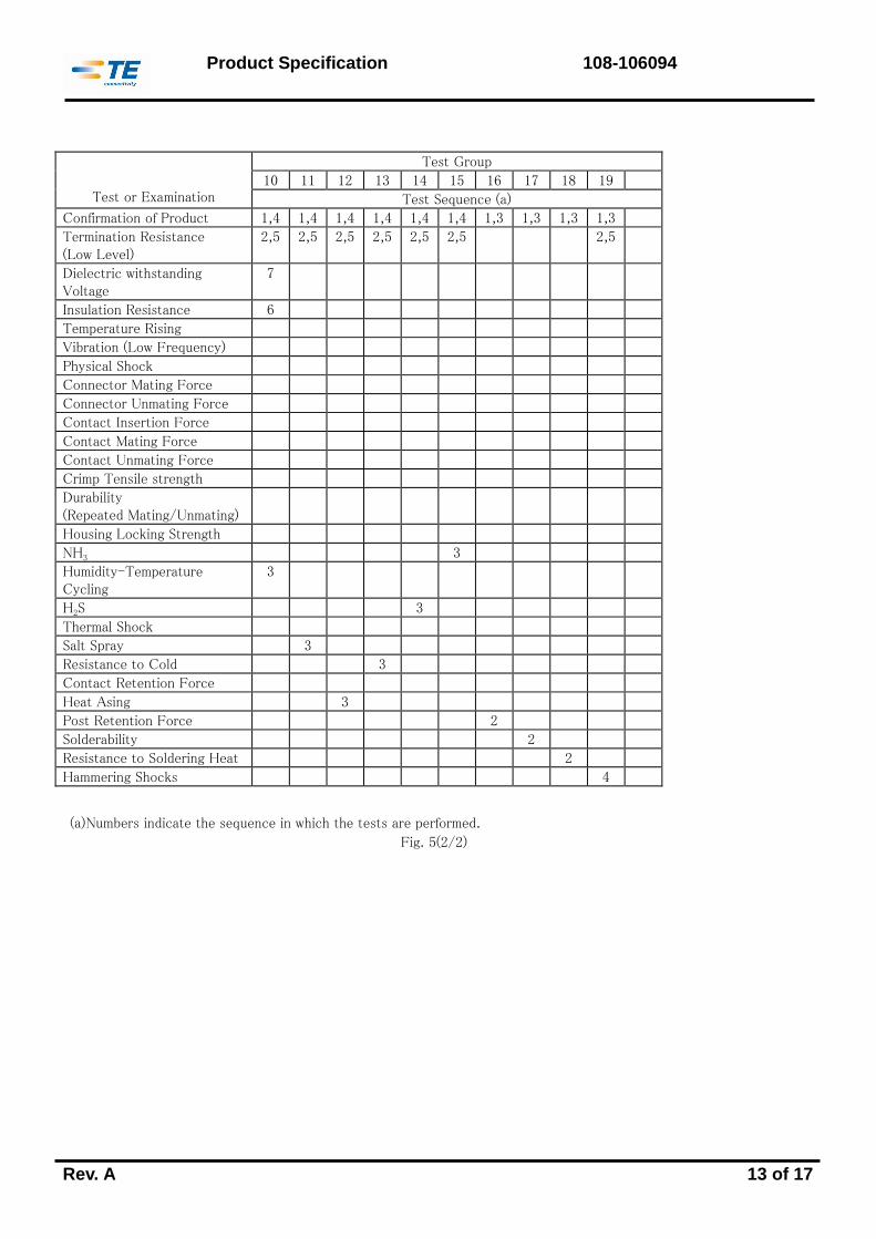
Test or Examination
Test Group
10 11 12 13 14 15 16 17 18 19
Test Sequence (a)
Confirmation of Product 1,4 1,4 1,4 1,4 1,4 1,4 1,3 1,3 1,3 1,3
Termination Resistance (Low Level)
2,5 2,5 2,5 2,5 2,5 2,5 2,5
Dielectric withstanding Voltage
7
Insulation Resistance 6
Temperature Rising
Vibration (Low Frequency)
Physical Shock
Connector Mating Force
Connector Unmating Force
Contact Insertion Force
Contact Mating Force
Contact Unmating Force
Crimp Tensile strength
Durability (Repeated Mating/Unmating)
Housing Locking Strength
NH3 3
Humidity-Temperature Cycling
3
H2S 3
Thermal Shock
Salt Spray 3
Resistance to Cold 3
Contact Retention Force
Heat Asing 3
Post Retention Force 2
Solderability 2
Resistance to Soldering Heat 2
Hammering Shocks 4
(a) Numbers indicate the sequence in which the tests are performed.
Fig. 5(2/2)

Product Specification 108-106094
Rev. A 14 of 17
4. Quality Assurance Provisions :
4.1 Test Conditions :
Unless otherwise specified, all the test shall be performed in any combination of the following test conditions.
Temperature : 15~35℃
Relative Humidity : 45~75 %
Atmospheric Pressure : 86.6~106.6 Kpa
Fig. 6
4.2 Tests :
4.2.1 Test Specimens :
The test specimens to be employed for the tests shall be conforming to the requirements specified in the applicable
product drawings. The crimped contacts shall be prepared in accordance with the requirements of applicable
application Specification, 114-5372, Crimping of Grace Signal Connector 3.3mm Pitch on the wires specified in Fig. 7 of
this specification.
4.2.2 Applicable Wires :
The wires to be used for crimping the samples for performance testing shall be conforming to the requirements specified
in Fig. 7.
Calculated
Cross-sectional
Area(mm2)
AWG
Diameter of a
Conductor (mm)
Number of
Conductors
Insulation Outer
Diameter (mm)
0.22 24 0.16 11 1.4
0.31 22 0.16 17 1.58
0.53 20 0.18 21 1.9
Fig. 7

Product Specification 108-106094
Rev. A 15 of 17
Wire-to-Boad Termination Type :
* Take the resistance of 75 mm wire only away
Fig. 8 Termination Resistance (Low Level) and Temperature Rising Vs. Current Measuring Methods
Fig. 9 Connector Mounting Methods of Low
Frequency Vibration and Physical Shock Tests
TE
Thermocouple
Attached here
Plug housing
Header Assy
75mm
Termination
Resistance
(Low Level)
Power Source

Product Specification 108-106094
Rev. A 16 of 17
Fig. 10 Gage Design for Contact Meting/Unmating Force Tests
Fig. 1
0.7±0.002

Product Specification 108-106094
Rev. A 17 of 17
Part Number Remarks
1971904 -□ TPA
□- 1971905 -□ Plug housing
□-1971906 -□ Header Assembly
1983780 -1 Rec contact
Appendix 1