Product Primary Application Page No. - Spray Nozzles · Spray Headers ... The patent-pending design...
92
����� ������� ����� ������� ����� �������� ����� � ����������
Transcript of Product Primary Application Page No. - Spray Nozzles · Spray Headers ... The patent-pending design...

������������
������������
�������������
����������������

Cover and inside back cover photos courtesy of MACSTEEL®, Republic Engineered Products, Inc. and United States Steel Corporation.
World Headquarters
Wheaton, IL USA
●
Sales Offices
Manufacturing Locations
Hudson, NH USA
Wheaton, IL USA
Belgium
Brazil
China
Germany
India
Italy
Japan
Korea
Legend

������������
������������
�������������
����������������
Table of Contents
Product Primary Application Page No.
CasterJet® Nozzles .............................Cooling/Continuous Casting ................................ 2 26010 Air Atomizing ................................................................................................................ 5
FullJet® Nozzles ..................................Cooling/Casting ..................................................... 6 HHX FullJet .............................................................................................................................. 7 HHCC FullJet ............................................................................................................................ 8 Standard/Square/Wide Angle ............................................................................................ 10 UniJet® ................................................................................................................................... 11 Vaneless ................................................................................................................................. 11Oval ......................................................................................................................................... 11Large capacity DistriboJet® ............................................................................................... 12P45075 ..................................................................................................................................... 12
VeeJet® Nozzles ..................................Lubrication/Cooling/Strip Wash-Off ................ 22 Quick VeeJet, UniJet ............................................................................................................ 23 Dovetail VeeJet ..................................................................................................................... 34 18897 Dovetail ........................................................................................................................ 36 XT VeeJet ............................................................................................................................... 39 Rectangular VeeJet .............................................................................................................. 40
DescaleJet® Nozzles .........................Descaling/Hot Strip Mill .................................... 41 AA214 ...................................................................................................................................... 4726180/26190/218 ..................................................................................................................... 50
Optimizing Spray Applications in Your Mill ................................................................... 43Flowline of Steelmaking ..................................................................................................... 44Areas of Your Mill that May Benefit from Spray System Automation ....................... 46
FlatJet® Nozzles ..................................Strip Wash-Off/Hot Strip Mill ........................... 54 FloodJet® Nozzles ................................................................................................................ 54
WashJet® Nozzles ..............................Strip Wash-Off/Hot Strip Mill ........................... 58
Laminar Flow ........................................Run-Off Table/Hot Strip Mill ............................. 60 Solid stream version ............................................................................................................. 60 Slit type ................................................................................................................................... 60
Spray Headers ......................................Lubrication/Strip Wash-Off/Cold Strip Mill ... 61 Automatic Brush Header ..................................................................................................... 61 Manual Brush Header .......................................................................................................... 61
WindJet® Air Control Nozzles ..........Strip Blow-Off/Cold Strip Mill .......................... 63 WindJet Nozzles ................................................................................................................... 63 Air Knife .................................................................................................................................. 65
Air Atomizing & AutomaticAutoJet® Spray Controllers ..............Spangling/Cold Strip Mill .................................. 66 VAU/VMAU ............................................................................................................................. 67 J-Series Air Atomizing ......................................................................................................... 68
WhirlJet® Spray Nozzles ...................Dust Control/Gas Cooling .................................. 78
SpiralJet® Spray Nozzles ..................Dust Control/Gas Cooling .................................. 79
FloMax® Nozzles and AutoJet® .....Emission Control/Gas Conditioning System ...................Scrubber/Gas Conditioning ............................... 86

2
������������������������������������������������������
Cooling/Continuous Casting
CasterJet Nozzles – Unmatched for Secondary Cooling in the Caster
The key to the superior performance of CasterJet nozzles is a unique process for mixing air and water. This results in:
• Improved surface quality through uniform spray distribution and reduced water buildup under rollers
• Reduced water costs -- More effective heat transfer means less water is required for cooling and large free-passage openings mean lower quality water can be used
• Increased operating versatility -- Variable water flows can accommodate a wide range of steel types and alloys
• Reduced maintenance costs -- Fewer nozzles needed per installation so fewer nozzles need to be maintained; self-aligning spray tips and new detachable expansion tubes speed replacement; and less puddling between support rollers reduces clean up time and extends roller life
• A potential 25% reduction in air consumption on a continuous caster while main-taining the same performance (compared with older designs)

33
������������������������������������������������������
Cooling/Continuous Casting
CasterJet Nozzles – How They Work
CasterJet nozzles use an atomization process based on a unique impingement principle involving three factors:
• A high velocity stream of water forced into an expansion chamber
• A target bolt, against which the water stream is shattered
• An air stream rushing past the target bolt to further break up the water stream
A recent design enhancement in the expansion chamber results in even more effi-cient mixing. CasterJet nozzles now provide more performance with a 25% reduc-tion in air consumption. This means new caster lines may require fewer or smaller compressors. On existing caster lines, some compressors can be turned off. This translates into lower energy costs and longer compressor life.
The nozzle’s target bolt also provides an even greater break-up efficiency than before and are now press-fit into the CasterJet nozzle body.
CasterJet nozzles offer a turndown ratio of 25:1. Flow can be reduced using water pressures as low as 5 psi (.3 bar) without a loss in performance. Wider operating ranges and consistent drop size distribution across the spray pattern allow greater flexibility in line speeds and the ability to run additional grades of steel.
Easy to Maintain
CasterJet extension tubes feature broached connections for detachability with a ferrule for connecting and a locating pin for safety. Because tubes are detachable, a wide range of lengths can be used. And, when breakouts occur, maintenance is easier – simply replace the tube and tip instead of the entire nozzle assembly.
The CasterJet spray tip, with a new snap ring assembly, is even easier to remove for fast and simple changes. The spray tips are self-aligning and the entire nozzle assembly features smooth, clean passages. Nozzle wear is low due to generally low operating pressures.
Specifications:
• Operating range: 2 to 12 gpm (7.6 to 45.4 l/min) at 45 psi air and 100 psi liquid (3 bar air and 7 bar liquid)
• Spray angles: 60° to 135°
• Materials: Stainless steel wear components including spray tip orifices and tar-get bolts. Brass bodies and extensions
• Inlet connection: 3/8” to 1/2”
IMPROVED EXPANSION CHAMBERREDUCES AIR CONSUMPTION
RE-DESIGNED TARGET BOLTIMPROVES BREAK-UP EFFICIENCY

4
������������������������������������������������������
Cooling/Continuous Casting
Water Flow Rate vs. Air Flow Rate at Constant Air Pressure
Performance
Dimensions 50070/50085
Ordering Info
50070/50085 Nozzle Set-Up
3/8NCJ – 3 – 120 – SS1/2NCJ – 8 – 120 – SS
Inlet Capacity Spray Material Conn. Size Angle
50070/50085 Assembly Style
50070 – BRSS + 50080 – 35050085 – BRSS + 50094 – 400
Assembly Style Length
Nozzle Set-up 50070-
Water Flow 7 bar (l/min)
Air Flow 3 bar (l/min)
_-NCJ-2-_-SS 7.6 147
_-NCJ-2.5-_-SS 9.5 162
_-NCJ-3-_-SS 11.4 174
_-NCJ-3.5-_-SS 13.2 242
_-NCJ-3.7-_-SS 15.1 255
_-NCJ-4-_-SS 18.9 284
_-NCJ-5-_-SS 24.6 289
_-NCJ-6.5-_-SS 30.0 441
Nozzle Set-up 50085-
Water Flow 7 bar (l/min)
Air Flow 3 bar (l/min)
_-NCJ-8-_-SS 34.0 517
_-NCJ-9-_-SS 40.0 718
_-NCJ-10-_-SS 45.0 634
_-NCJ-12-_-SS 57.0 634

55
������������������������������������������������������
Cooling/Continuous Casting26010 Air Atomizing
26010 Air Atomizing Nozzles Provide Softer Continuous Cast Cooling
If you’re only running a few grades of steel, our 26010 Air Atomizing nozzle may be a suitable alternative to our CasterJet® nozzles. An air mist style nozzle, the 26010 provides softer, impingement-type cooling – performance typically achieved by hydraulic nozzles. Performance can be visually identified by rings on air cap.
Specifications:
• All brass construction
• Inlet connection: 1/4”
26010
Dimensions
Performance
26010 – 1 – 1/4J
Ordering Info
26010 Air Atomizing Nozzle
Spray ID Nozzle Set-Up Rings Body
Nozzle Assembly No.
Number of I.D. Rings
Spray Performance
Spray Angle (degree)Pressure (bar) Capacity
Air Fluid Air (NI/min) Water (l/min)
26010-0-1/4J NONE 2.8 2.6 85 1.9 90
26010-1-1/4J 1 2.8 2.3 275 3.8 90
26010-2-1/4J 2 2.8 2.4 297 5.7 90
26010-3-1/4J 3 2.8 4.1 176 10.6 90
26010-4-1/4J 4 2.8 2.4 297 5.7 120
26010-5-1/4J 5 2.8 4.1 156 10.6 120

6
������������������������������������������������������
Cooling/Casting
FullJet Nozzles – Uniform Distribution Enhances Steel Quality in Every Area of Your Mill
Hot spots, cracks and defects – all costly but common problems that can lead to waste. One way to avoid quality problems like these is to use our FullJet spray nozzles. These nozzles feature a unique vane design with large flow passages to provide a uniform spray over a wide range of flow rates and pressures. This even and consistent spray coverage results in center-to-edge cooling and defect-free steel.
Our line of FullJet nozzles is extensive. Choose from a wide assortment of styles, sizes, capacities, connections, spray angles, impact areas, materials and more.
Common uses for FullJet nozzles include:
• Uniform cooling in continuous cast slabs, continuous cast billets, finishing
• Fast and uniform quenching
• Thorough liquor flushing
��������������

77
������������������������������������������������������
Cooling/Casting
HHX FullJet Nozzles – Provide Uniform Distribution, Reliable Operation and Simplified Maintenance in Billet Casters
Quality sprays contribute to better steel and increase the efficiency of your caster, and our HHX FullJet nozzles do exactly that – provide uniform cooling to ensure quality problems like diagonal cracks are avoided.
Key benefits and features include:
• A wide range of nozzle sizes allows you to select different spray densities to cus-tomize the spray zone cooling
• The HHX nozzle body features a hex body and allows the use of standard sockets for easy installation and removal
• A staked-in vane design ensures the vane is secure and will not fall out during caster operation
Specifications:
• Capacities range from .50 to 2.2 gpm (1.9 to 8.4 l/min) at 10 psi (.7 bar)
• All brass construction with a staked vane
• Inlet connections: 1/4” and 3/8”
HHX
Dimensions
Performance
1/4 HHX - 5
Ordering Info
Inlet Nozzle Capacity Conn. Type Size
HHX FullJet Spray Nozzle
* At stated pressure in bar.
Nozzle Inlet Conn. NPT or
BSPT (in.)Nozzle No.
Orifice Dia.
Nom.
Max. Free Passage
Dia. Capacity (Liters per minute)* Spray Angle
Degree*
mm mm .5 .7 1.5 2 3 4 5 6 7 10 .5 1.5 6
1/4
1/4HHX-5 1.95 1.3 1.6 1.9 2.7 3.1 3.7 4.2 4.7 5.1 5.5 6.5 60 65 61
1/4HHX-6.5 2.4 1.6 2.1 2.5 3.5 4.0 4.8 5.5 6.1 6.7 7.1 8.4 45 50 46
1/4HHX-8 2.8 1.2 2.6 3.0 4.3 4.9 6.0 6.8 7.5 8.2 8.8 10.4 68 80 76
1/4HHX-10 2.8 1.6 3.3 3.8 5.4 6.2 7.4 8.5 9.4 10.2 11.0 13.0 58 67 61
1/4HHX-12 3.2 1.6 3.9 4.6 6.5 7.4 8.9 10.2 11.3 12.3 13.2 15.5 71 81 72
1/4HHX-14.5 3.6 1.6 4.7 5.5 7.8 9.0 10.8 12.3 13.7 14.8 15.9 18.8 78 89 75
3/8
3/8HHX-15 3.6 2.4 4.9 5.7 8.1 9.3 11.2 12.7 14.1 15.4 16.5 19.4 64 67 61
3/8HHX-18 4.0 2.4 5.9 6.9 9.7 11.1 13.4 15.3 16.9 18.4 19.8 23 77 86 73
3/8HHX-20 4.4 2.8 6.5 7.6 10.8 12.4 14.9 17.0 18.8 20 22 26 76 80 73
3/8HHX-22 4.8 2.8 7.2 8.4 11.9 13.6 16.4 18.7 21 23 24 28 87 90 82

8
������������������������������������������������������
Cooling/Casting
Dimensions
HHCC
HHCC FullJet Nozzles – The Most Stable, Uniform Full Cone Spray Available
Typical full cone nozzles deliver water in a full cone spray. But liquid distribution can vary. Everything gets wet, but some spots get wetter than others. And this can lead to costly defects resulting from uneven cooling. The patent-pending design of our HHCC FullJet delivers a spray that is more uniform across the cone. This results in consistent, controlled cooling that meets even the most stringent demands.
Here’s how the HHCC FullJet helps control temperature of the strand, a critical com-ponent of maximizing uptime with high-speed continuous casting machines:
• New staked vane design yields a more uniform and stable spray over the operat-ing range of 10 to 80 psi (.7 to 5.5 bar). Changes in pressure do not impact the nozzle’s spray angle
• The vanes are precisely matched with each nozzle size to ensure exact perfor-mance
• Obtain the mass water flux you need for every casting application through a wide selection of nozzle sizes. There’s a 25% nominal flow rate increase at every size increment, simplifying layout of flow rates for each segment
Specifications:
• Capacities range from .65 to 3.2 gpm (2.5 to 12.1 l/min) at 10 psi (.7 bar)
• Brass construction with a staked vane
• Inlet connections: 1/4”, 3/8” and 1/2”

99
������������������������������������������������������
Cooling/Casting
Performance
HHCC
1/4 HHCC – 6.5
Ordering Info
Inlet Nozzle Capacity Conn. Type Size
HHCC FullJet Spray Nozzle
��������������
���
���
* At stated pressure in bar.
Nozzle Inlet Conn.
NPT or BSPT (in.)
Nozzle No.
Orifice Dia.
Nom.
Max. Free
Passage Dia.
Capacity (Liters per minute)* Spray Angle
Degree*
mm mm .7 1.5 2 3 3.5 4 5 5.5 6 7 1.5 3 6
1/4
1/4HHCC-6.5 2.1 1.7 2.5 3.4 4.2 4.9 5.3 5.7 6.1 6.4 6.8 7.2 68 68 68
1/4HHCC-8 2.2 1.8 3.0 4.2 4.9 5.7 6.4 6.8 7.6 7.9 8.3 8.7 68 68 68
1/4HHCC-10 2.5 1.9 3.8 5.3 6.4 7.2 8.3 9.1 9.5 10.2 6.6 11.4 74 74 74
1/4HHCC-12.5 2.7 2.2 4.7 6.4 7.9 9.1 10.2 11 11.7 12.5 13.2 14 74 74 74
3/8 3/8HHCC-15 3.3 2.6 5.7 7.9 9.5 11 12.1 13.2 14 15.1 15.9 16.7 74 74 74
1/2
1/2HHCC-20 2.8 2.9 7.6 10.6 12.9 14.4 16.3 17.4 18.9 20.1 21.2 22 74 74 74
1/2HHCC-25 3.0 3.0 9.5 13.2 15.9 18.2 20.1 22 23.5 25 26.5 27.6 74 74 74
1/2HHCC-32 4.3 2.8 12.1 17 20.4 23.1 25.7 28 29.9 31.8 33.7 35.6 74 74 74

10
������������������������������������������������������
Cooling/Casting
Removable cap and vane1/8” to 1/2” NPT or BSPT (M)
FullJet Nozzles Are Ideal for Cooling in Semi-Finishing, Quenching, Liquor Flushing and More
Our FullJet nozzles produce a solid cone-shaped spray pattern consisting of medi-um to large sized drops with a round impact area. The spray pattern is uniform, providing even and thorough center-to-edge coverage to enhance steel quality. A unique vane design with large flow passages is responsible for the uniform coverage.
There’s a FullJet nozzle for almost every cooling application in your mill. The noz-zles are available in a wide variety of configurations, capacities, connections, mate-rials, spray angles and sizes. Many models are available with a choice of impact areas of wide angle, square and oval.
Removable cap and vane1/8” to 1/2” NPT or BSPT (F)
G GG
GGD
Wall mountedRemovable cap and vane
1/8” to 1/2” NPT or BSPT (M)
GD
Wall mountedRemovable cap and vane
1/8” to 1/2” NPT or BSPT (F)
GA
Angle typeRemovable cap and vane
1/8” to 1/2” NPT or BSPT (F)
GGA
Angle typeRemovable cap and vane
1/8” to 1/2” NPT or BSPT (M)
HH
One-piece body1/8” to 1” NPT or BSPT (M)
• HH FullJet nozzles have a one-piece body and non-removable vanes.
• Available in standard spray, wide angle spray, square spray and wide angle square spray.
• G and GG FullJet nozzles feature removable caps and vanes for easy cleaning and inspection. The nozzle body can remain in the header or manifold.
• Available in standard spray, wide angle spray and square spray.
• GA and GGA FullJet nozzles have a right angle design for installation on a pipe extension over the center of a spray zone or in a side-tapped header or manifold. The spray is projected from nozzle at an axis 90° from the axis of the nozzle inlet.
• Available in standard spray and wide angle spray.
• GD and GGD FullJet nozzles feature a wall mount connec-tion for installations where the piping for the nozzle must be installed on the exterior of the room, vessel or pipeline into which the nozzle will spray.
• Available in standard spray.

1111
������������������������������������������������������
Cooling/Casting
H
Removable vane/cast body1-1/4” to 3” NPT or BSPT (F)
H
One piece body/vane3/4” to 1” NPT or BSPT (F)
One-piece spray tipwith vane
• TG UniJet spray tips are part of our UniJet System. Tips can be removed and replaced while the nozzle body remains in posi-tion. Plus, a variety of other UniJet components are available – strainers, valves, connectors and more.
• Available in standard spray, wide angle spray and square spray.
UniJet TG Spray Tip
• H FullJet nozzles have a one-piece body with vane or a removable vane/cast body.
• Available in standard spray, wide angle spray, square spray and wide angle square spray.
Spray tip
T female body or
TT male body
Tip retainer
UniJet Bodies
GANV GGANV
• Vaneless FullJet nozzles feature completely unrestricted internal flow passages with no vane. Spray is projected from the nozzle in a full cone pattern at an axis 90° from the axis of the nozzle inlet and is best used for applica-tions requiring a coarser spray.
GVL GGVL
Removable cap and vane 3/8” NPT or BSPT (M)
• Oval FullJet nozzles have a solid cone-shaped spray with an oval impact area that has a width approximately one-half its length. These nozzles are well suited for inten-sive cooling applications that require a heavy spray to be projected between rollers to the target surface. Oval FullJet nozzles feature removable caps and vanes for easy inspection and cleaning.
Vaneless/removable cap1/4” to 1/2” NPT
or BSPT (F)
Vaneless/removable cap1/4” to 1/2” NPT
or BSPT (M)
Removable cap and vane3/8” NPT or BSPT

12
������������������������������������������������������
Cooling/Casting
2” to 8” NPT or BSPT (F) (80°/95° orifice shown)
2” to 8” NPT or BSPT (M) (50°/65° orifice shown)
DistriboJet
• DistriboJet FullJet large capacity nozzles feature an internal vane that is cast as part of the nozzle. Extra-large flow passages and a large open orifice assure non-clogging operation. Spray angles range from 50° to 95°.
• The operating range is 1 to 60 psi (.07 to 4 bar) with a full cone spray pattern developing at 1 psi (.07 bar). The 50° to 65° nozzles have specially designed grooved orifices for accurate flow rates and spray angle control. The 80° to 95° nozzles have smooth orifices with larger diameters for the same flow rates.
R RR
P45075 FullJet Nozzles
• Ideal for use on risers in billet casting, the P45075 FullJet nozzle features a low profile design. Like other FullJet nozzles, the P45075 provides a full cone pattern with even distribution and uses a secure, staked-in vane design. Plus, the hex body allows use of socket wrench for easy installation and removal.
• BSPP (F) inlet eliminates exposed thread on headers.
1/4” to 3/8” BSPP (F)

1313
������������������������������������������������������
Cooling/Casting
Performance – Standard FullJet Nozzles
Maximum Free Passage Diameter is the maximum diameter as listed of foreign matter that can pass through the nozzle without clogging.
Ordering Info
Inlet Nozzle Material Capacity Conn. Type Code Size
FullJet Spray Nozzle
1/4 G – SS 5
*At the stated pressure in bar.
Nozzle Inlet
Conn. NPT or BSPT (in.)
Nozzle Type Capa-
city Size
Orifice Dia.
Nom. (mm)
Max. Free
Passage Dia.
(mm)
Capacity (Liters per minute)* Spray Angle Degree*
Standard Type Wall Mounted Angle
G H GG HH GD GGD GA GGA .5 .7 1.5 2 3 4 5 6 7 10 .5 1.5 6
1/8
● ● ● ● ● 1 .79 .64 — .38 .54 .62 .74 .85 .94 1.0 1.1 1.3 — 58 53● ● 1.5 1.2 .64 .49 .57 .81 .93 1.1 1.3 1.4 1.5 1.7 1.9 52 65 59● ● ● ● ● ● ● 2 1.2 1.0 .65 .76 1.1 1.2 1.5 1.7 1.9 2.0 2.2 2.6 43 50 46● ● ● ● ● ● ● 3 1.5 1.0 .98 1.1 1.6 1.9 2.2 2.5 2.8 3.1 3.3 3.9 52 65 59● ● ● ● ● ● ● 3.5 1.6 1.3 1.1 1.3 1.9 2.2 2.6 3.0 3.3 3.6 3.9 4.5 43 50 46
● ● 3.9 2.0 1.0 1.3 1.5 2.1 2.4 2.9 3.3 3.7 4.0 4.3 5.1 77 84 79● ● ● ● ● ● ● 5 2.0 1.3 1.6 1.9 2.7 3.1 3.7 4.2 4.7 5.1 5.5 6.5 52 65 59
1/4 ● ● ● ● ● ● ● 6.5 2.4 1.6 2.1 2.5 3.5 4.0 4.8 5.5 6.1 6.7 7.1 8.4 45 50 46● ● ● ● ● ● ● 10 3.2 1.6 3.3 3.8 5.4 6.2 7.4 8.5 9.4 10.2 11.0 13.0 58 67 61
● ● 12.5 3.2 1.6 4.1 4.8 6.8 7.7 9.3 10.6 11.8 12.8 13.7 16.2 69 74 68
3/8 ● ● ● ● ● ● ● 9.5 2.6 2.4 3.1 3.6 5.1 5.9 7.1 8.1 8.9 9.7 10.4 12.3 45 50 46● ● ● ● ● ● ● 15 3.6 2.4 4.9 5.7 8.1 9.3 11.2 12.7 14.1 15.4 16.5 19.4 64 67 61
1/2
● ● ● ● ● ● 16 3.5 3.2 5.2 6.1 8.7 9.9 11.9 13.6 15.1 16.4 17.6 21 48 50 46● ● ● ● ● ● ● 25 4.6 3.2 8.2 9.5 13.5 15.4 18.6 21 24 26 27 32 64 67 61● ● ● ● 32 5.2 3.6 10.4 12.2 17.3 19.8 24 27 30 33 35 41 72 75 68● ● ● ● ● 40 6.2 3.6 13.1 15.2 22 25 30 34 38 41 44 52 88 91 83
● ● 50 6.7 4.0 16.3 19.1 27 31 37 42 47 51 55 65 91 94 86
3/4● ● 2.5 4.9 4.4 9.6 11.2 15.9 18.2 22 25 28 30 32 38 48 50 46● ● 4.0 6.4 4.4 15.4 18.0 26 29 35 40 44 48 52 61 67 70 63● ● 7.0 9.5 5.2 27 31 45 51 61 70 78 84 91 107 89 92 84
1
● ● 7.0 8.3 5.6 27 31 45 51 61 70 78 84 91 107 67 68 62
● ● 8.0 9.5 5.6 31 36 51 58 70 80 89 97 104 122 72 81 82
● ● 10 11.9 5.6 38 45 64 73 88 100 111 121 130 153 78 90 94
● ● 12 11.9 6.4 46 54 77 87 105 120 133 145 155 183 89 92 84
1-1/4 ● 12 10.7 6.4 46 54 77 87 105 120 133 145 155 183 66 70 60
1-1/2● 10 9.5 8.7 38 45 64 73 88 100 111 121 130 153 64 67 58
● 16 12.7 8.7 62 72 102 117 138 157 178 193 206 242 73 76 66
2● 40 21.0 11.1 154 180 255 295 350 400 445 485 520 610 78 80 70
● 50 23.8 14.3 192 225 320 365 440 500 560 610 650 770 83 85 75
● 60 28.6 14.3 230 270 385 440 530 600 670 730 780 920 98 100 86
2-1/2● 60 24.6 14.3 230 270 385 440 530 600 670 730 780 920 76 78 68
● 70 28.6 14.3 270 315 450 510 620 700 780 850 910 1070 79 82 72
● 80 28.6 17.5 310 360 510 590 700 800 890 970 1040 1220 86 88 77
3● 90 30.2 17.5 350 405 580 660 790 900 1000 1090 1170 1380 86 89 77
● 100 32.5 17.5 385 450 640 730 880 1000 1110 1210 1300 1530 92 95 83
● 120 34.9 20.6 465 540 770 880 1060 1200 1340 1450 1560 1840 102 105 89
4
● 160 42.9 19.1 620 720 1020 1170 1410 1610 1780 1930 2080 2450 87 90 70
● 180 47.2 22.2 700 810 1150 1310 1580 1810 2000 2170 2340 2750 92 95 83
● 200 50.8 25.4 770 900 1280 1460 1760 2010 2220 2420 2590 3060 97 100 87
● 210 54.8 25.4 810 950 1340 1530 1850 2110 2330 2540 2720 3210 102 105 91

14
������������������������������������������������������
Cooling/Casting
Maximum Free Passage Diameter is the maximum diameter as listed of foreign matter that can pass through the nozzle without clogging.
Performance – Wide Angle, Square and Extra Wide Angle FullJet Nozzles
Ordering Info
Inlet Nozzle Material Capacity Conn. Type Code Size
FullJet Spray Nozzle
1/4 G – SS 14W
Nozzle Inlet Conn. NPT or
BSPT (in.)
Nozzle Type Capa-city Size
Max. Free Passage
Dia.(mm)
Capacity (Liters per minute)* Spray Angle Degree*
G H GG HH GA GGA 0.3 0.5 1 2 3 4 5 6 0.5 1.5 6
1/8
● ● 1.5W .64 — — .67 .90 1.1 1.3 1.4 1.5 — 120 86
● ● ● 2.8W 1.0 — — 1.2 1.7 2.0 2.3 2.5 2.7 — 120 102
● ● ● ● ● 4.3W 1.0 — — 1.9 2.6 3.1 3.5 3.9 4.2 — 120 102
● ● ● 4.8SQ 1.3 1.2 1.6 2.2 3.0 3.6 4.1 4.5 4.9 48 63 57
● ● 5.6W 1.0 — 1.8 2.5 3.4 4.0 4.6 5.1 5.5 — 120 102
● ● ● 6SQ 1.3 1.5 2.0 2.7 3.7 4.5 5.1 5.6 6.1 60 66 60
● ● ● ● ● 8W 1.3 — 2.6 3.6 4.8 5.8 6.6 7.2 7.8 — 120 103
1/4
● ● 10W 1.3 2.6 3.3 4.5 6.0 7.2 8.2 9.1 9.8 112 120 103
● ● ● 10SQ 1.6 2.6 3.3 4.5 6.2 7.4 8.5 9.4 10.2 62 67 61
● ● 12W 1.3 3.1 3.9 5.3 7.3 8.7 9.8 10.9 11.8 114 120 103
● ● ● 12SQ 1.6 3.1 3.9 5.4 7.4 8.9 10.2 11.3 12.3 70 75 68
● ● ● ● ● 14W 1.6 3.7 4.6 6.2 8.5 10.2 11.5 12.7 13.7 114 120 103
● 14WSQ 1.6 3.7 4.6 6.2 8.5 10.1 11.5 12.7 13.7 99 101 93
14.5SQ 1.6 3.7 4.7 6.5 9.0 10.8 12.3 13.7 14.8 78 82 75
3/8
● ● ● 18SQ 2.4 4.6 5.9 8.1 11.1 13.4 15.3 17.0 18.4 71 75 68
● ● ● ● ● 20W 2.4 5.2 6.6 8.9 12.1 14.5 16.5 18.1 19.6 114 120 104
● 20WSQ 2.4 5.2 6.6 8.9 12.1 14.5 16.5 18.1 19.6 104 110 94
1/2
● ● ● 29SQ 3.2 7.5 9.5 13.0 17.9 22 25 27 30 71 75 68
● ● ● 30W 2.8 7.9 9.9 13.4 18.1 22 25 27 29 114 120 108
● ● ● ● ● 35W 3.2 9.2 11.5 15.6 21 25 29 32 34 114 120 108
● 35WSQ 3.2 9.2 11.5 15.6 21 25 29 32 34 104 110 102
● ● ● 40W 3.2 10.5 13.1 17.8 24 29 33 36 39 114 120 108
● ● ● 45W 3.6 11.8 14.8 20 27 33 37 41 44 114 120 110
● ● ● ● ● 50W 4.0 13.1 16.4 22 30 36 41 45 49 114 120 112
3/4
● ● 6W 4.4 18.4 23 31 42 51 58 64 69 115 120 112
● 50SQ 4.4 12.9 16.3 22 31 37 42 47 51 71 75 68
● ● 71WSQ 4.4 18.4 23 31 42 51 58 64 69 105 110 102
1● ● 11W 5.6 34 42 57 78 93 106 116 126 107 120 117
● ● 130WSQ 5.6 34 42 57 78 93 106 116 126 107 110 107
2
● 47W 11.1 144 181 254 335 400 455 500 540 120 124 119
● 290SQ 11.1 75 95 130 179 215 250 275 300 66 70 64
● 560WSQ 11.1 144 181 245 335 400 455 500 540 110 114 109
2-1/2● 70W 14.3 215 270 365 495 600 680 750 810 120 125 119
● 830WSQ 14.3 215 270 365 495 600 680 750 810 110 115 109
*At the stated pressure in bar.

1515
������������������������������������������������������
Cooling/Casting
Performance – Standard, Square and Wide Angle Spray UniJet Nozzle with TG Tip
Maximum Free Passage Diameter is the maximum diameter as listed of foreign matter that can pass through the nozzle without clogging. Ordering Info
UniJet Spray Nozzle
1/4 T – SS + TG – SS 10
Inlet Nozzle Material Tip Material Capacity Conn. Type Code Type Code Size
Nozzle Body Spray Tip
Nozzle Inlet Conn. NPT or
BSPT (in.)
Nozzle Type Capacity Size
Max. Free Passage
Dia.(mm)
Capacity (Liters per minute)* Spray Angle Degree*
TG TG-W TG-SQ 0.3 0.5 0.7 2 3 4 5 6 0.3 0.7 6
1/8
● 2.8W 1.0 — — 1.1 1.7 2.0 2.3 2.5 2.7 — 120 102
● 4.3W 1.0 — — 1.6 2.6 3.1 3.5 3.9 4.2 — 120 102
● 5.6W 1.0 — 1.8 2.1 3.4 4.0 4.6 5.1 5.5 — 120 102
● 8W 1.3 — 2.6 3.0 4.8 5.8 6.6 7.2 7.8 — 120 103
1/4
● 0.3 .41 — — — .19 .22 .25 .28 .31 — 50 61
● 0.4 .46 — — — .25 .30 .34 .38 .41 — 56 63
● 0.5 .51 — — — .31 .37 .42 .47 .51 — 56 63
● 0.6 .51 — — — .37 .45 .51 .57 .61 — 54 62
● 0.7 .51 — — — .43 .52 .60 .66 .72 — 54 63
● 1 .64 — — — .62 .74 .85 .94 1.0 — 58 53
● 2 1.0 — — .76 1.2 1.5 1.7 1.9 2.0 — 50 46
● 2.8W 1.0 — — 1.1 1.7 2.0 2.3 2.5 2.7 — 120 102
● 3 1.0 — — 1.1 1.9 2.2 2.5 2.8 3.1 — 65 59
● 3.5 1.3 — — 1.3 2.2 2.6 3.0 3.3 3.6 — 50 46
● 4.3W 1.0 — — 1.6 2.6 3.1 3.5 3.9 4.2 — 120 102
● 5 1.3 — — 1.9 3.1 3.7 4.2 4.7 5.1 — 65 59
● 5.6W 1.0 — 1.8 2.1 3.4 4.0 4.6 5.1 5.5 — 120 102
● 6SQ 1.3 1.5 2.0 2.7 3.7 4.3 4.9 5.8 6.3 60 66 60
● 6.5 1.6 2.1 2.5 3.5 4.0 4.8 5.5 6.1 6.7 45 50 46
● 8W 1.3 — 2.6 3.0 4.8 5.8 6.6 7.2 7.8 — 120 103
● 8SQ 1.3 2.1 2.6 3.6 4.9 5.9 6.7 7.4 8.3 70 75 68
● 10 1.6 3.3 3.8 5.4 6.2 7.4 8.5 9.4 10.2 58 67 61
● 10W 1.3 2.6 3.3 3.8 6.0 7.2 8.2 9.1 9.8 112 120 103
● 10SQ 1.6 2.6 3.3 4.5 6.3 7.5 8.5 9.5 10.2 62 66 60
● 12W 1.3 3.1 3.9 4.6 7.3 8.7 9.8 10.9 11.8 114 120 103
● 12SQ 1.6 3.1 3.9 5.4 7.4 8.9 10.2 11.3 12.3 70 75 68
● 14W 1.6 3.7 4.6 5.3 8.5 10.1 11.5 12.7 13.7 114 120 103
3/8 ● 18SQ 2.4 4.6 5.9 8.1 11.1 13.4 15.3 17.0 18.4 71 75 68
*At the stated pressure in bar.

16
������������������������������������������������������
Cooling/Casting
Performance – Oval Spray FullJet Nozzles
Performance – Vaneless FullJet Nozzles
Ordering Info
Maximum Free Passage Diameter is the maximum diameter as listed of foreign matter that can pass through the nozzle without clogging.
Inlet Nozzle Material Capacity Conn. Type Code Size
Oval Spray Nozzle
3/8 G – SS 4.9VL
Vaneless Spray Nozzle
1/4 GANV – SS 10
Inlet Nozzle Material Capacity Conn. Type Code Size
*At the stated pressure in bar.
Nozzle Inlet Conn. NPT or
BSPT (in.)
Capa-city Size
Max. Free Passage Dia. (mm)
Capacity (Liters per minute) * Spray Angle Degree*
1 2 3 4 5 7 101 3 7 10
A B A B A B A B
3/8
4.9VL 1.0 2.2 3.0 3.6 4.2 4.6 5.4 6.3 104 66 90 60 86 52 83 47
6.5VL 1.3 2.9 4.0 4.8 5.5 6.1 7.1 8.4 106 64 95 60 85 50 81 45
8.1VL 1.3 3.6 5.0 6.0 6.9 7.6 8.9 10.5 102 64 100 65 84 50 80 45
9.2VL 1.3 4.1 5.7 6.8 7.8 8.7 10.1 11.9 103 65 100 65 86 51 81 46
Nozzle Inlet Conn. NPT
or BSPT (in.)
Capa-city Size
Orifice Dia.
Nom. (mm)
Max. Free
Passage Dia. (mm)
Capacity (Liters per minute)* Spray Angle Degree*
0.3 0.5 1 1.5 2 3 4 5 6 7 0.5 1.5 6
1/4
5 2.8 2.0 1.3 1.6 2.3 2.8 3.2 3.9 4.6 5.1 5.6 6.0 68 75 82
7 3.2 2.4 1.9 2.3 3.2 3.9 4.5 5.5 6.4 7.1 7.8 8.4 68 75 82
8 4.0 2.8 2.2 2.6 3.6 4.5 5.2 6.3 7.3 8.2 8.9 9.6 75 80 85
10 4.0 3.2 2.7 3.2 4.6 5.6 6.4 7.9 9.1 10.2 11.2 12.1 75 80 85
11 4.0 3.6 3.0 3.5 5.0 6.1 7.1 8.7 10.0 11.2 12.3 13.3 75 80 85
3/8
11 4.4 3.2 3.0 3.5 5.0 6.1 7.1 8.7 10.0 11.2 12.3 13.3 75 85 83
13 4.4 3.6 3.5 4.2 5.9 7.3 8.4 10.3 11.9 13.3 14.5 15.7 75 85 83
16 4.4 4.0 4.3 5.2 7.3 8.9 10.3 12.6 14.6 16.3 17.9 19.3 75 85 83
20 5.6 4.4 5.4 6.4 9.1 11.2 12.9 15.8 18.2 20 22 24 75 85 83
23 5.6 4.8 6.2 7.4 10.5 12.8 14.8 18.2 21 23 26 28 75 85 83
26 6.0 5.2 7.0 8.4 11.9 14.5 16.8 21 24 27 29 31 75 85 83
29 6.0 5.6 7.8 9.3 13.2 16.2 18.7 23 26 30 32 35 75 85 83
33 7.5 6.0 8.9 10.6 15.0 18.4 21 26 30 34 37 40 75 85 83
1/2
32 7.9 5.2 8.0 10.3 14.6 17.9 20 25 29 33 36 39 85 90 95
40 7.9 6.0 10.0 12.9 18.2 22 26 32 36 41 45 48 85 90 95
48 7.9 7.1 12.0 15.5 22 27 31 38 44 49 54 58 85 90 95°
56 9.9 7.5 14.0 18.0 26 31 36 44 51 57 63 68 85 90 95°
64 9.9 8.3 16.0 21 29 36 41 51 58 65 71 77 85 90 95
72 9.9 9.1 18.0 23 33 40 46 57 66 73 80 87 85 90 95
*At the stated pressure in bar.

1717
������������������������������������������������������
Cooling/Casting
P45075 Spray Nozzle
Maximum Free Passage Diameter is the maximum diameter as listed of foreign matter that can pass through the nozzle without clogging.
Performance - DistriboJet Spray Nozzles 50°/65°/80°/95°
Performance – P45075
Ordering Info
DistriboJet Spray Nozzle
2 RR – SS 50 45
Inlet Nozzle Material Spray Capacity Conn. Type Code Angle Size
P45075 – 1/4H – SS – 4 – 65
Nozzle Inlet Nozzle Material Capacity Spray Prefix Conn. Type Code Size Angle
Nozzle Inlet
Conn. NPT or BSPT (in.)
Nozzle Type
Capacity Size
Orifice Dia.
Nom. (mm)
Capacity (Liters per minute)* R RR Spray Angle Degree* Spray Angle Degree*
50 65 80 95 50 65 80 95 1 3 5 7 10 15 20 30 40 60
2
● ● 45 — 122 168 205 255 300 355 425 485 590 670 ● ● 45 — 122 168 205 255 300 355 425 485 590 670 ● ● 45 29 122 168 205 255 300 355 425 485 590 670
● ● 60 — 163 225 270 340 400 470 570 650 780 890 ● ● 60 36.1 163 225 270 340 400 470 570 650 780 890
2-1/2
● ● 70 — 190 260 315 400 465 550 660 760 910 1040 ● ● 70 — 190 260 315 400 465 550 660 760 910 1040 ● ● 70 36.5 190 260 315 400 465 550 660 760 910 1040
● ● 90 — 245 335 405 510 600 710 850 970 1170 1330 ● ● 90 44.8 245 335 405 510 600 710 850 970 1170 1330
3
● ● 110 — 300 410 495 630 730 860 1040 1190 1430 1630 ● ● 110 — 300 410 495 630 730 860 1040 1190 1430 1630 ● ● 110 46.4 300 410 495 630 730 860 1040 1190 1430 1630
● ● 140 — 380 530 630 800 930 1100 1320 1510 1820 2070 ● ● 140 57.2 380 530 630 800 930 1100 1320 1510 1820 2070
*At the stated pressure in bar.
Nozzle Inlet Conn. NPT or
BSPT (in.)Nozzle No.
Orifice Dia. Nom.
(mm)
Max. Free Passage Dia. (mm)
Capacity (Liters per minute)* Spray Angle Degree*
.7 1.4 2 2.8 4 5.5 7 20 80
1/4
P45075-1/4H-4-65 1.9 1.2 1.6 2.2 2.6 3.1 3.6 4.2 4.5 65 65P45075-1/4H-5.5-65 2.1 1.3 2.1 3.0 3.6 4.2 4.9 5.5 6.0 65 65P45075-1/4H-7.5-45 2.5 1.3 2.9 4.1 5.0 5.7 6.8 7.7 8.4 45 45P45075-1/4H-7.5-65 2.5 1.3 2.9 4.1 5.0 5.7 6.8 7.7 8.4 65 65
3/8
P45075-3/8H-3-65 1.5 1.0 1.0 1.5 1.8 2.1 2.3 2.7 3.0 65 65P45075-3/8H-3.5-65 1.5 1.0 1.0 1.5 1.8 2.1 2.3 2.7 3.0 65 65P45075-3/8H-4-65 1.8 1.2 1.6 2.2 2.6 3.1 3.6 4.2 4.5 65 65P45075-3/8H-5-65 2.1 1.6 1.7 2.5 3.0 3.5 4.3 4.9 5.5 65 65P45075-3/8H-5.5-65 2.1 1.3 2.1 3.0 3.6 4.2 4.9 5.5 6.0 65 65P45075-3/8H-7-45 2.1 1.3 2.1 3.0 3.6 4.2 4.9 5.5 6.0 45 45P45075-3/8H-7-65 2.1 1.3 2.1 3.0 3.6 4.2 4.9 5.5 6.0 65 65P45075-3/8H-8.5-65 2.6 1.6 3.2 4.6 5.6 6.4 7.5 8.5 9.3 65 65P45075-3/8H-10-45 2.9 2.8 3.6 5.1 6.1 7.0 8.7 9.4 10.3 45 55P45075-3/8H-10-65 2.8 1.6 3.6 5.1 6.1 7.0 8.7 9.4 10.3 65 65P45075-3/8H-14-60 2.8 1.6 3.6 5.1 6.1 7.0 8.7 9.4 10.3 60 60P45075-3/8H-22-60 4.2 3.0 8.2 11.4 13.2 14.9 17.4 19.5 22 60 55P45075-3/8H-22-90 4.2 3.0 8.2 11.4 13.2 14.9 17.4 19.5 22 90 87P45075-3/8H-7W-120 2.2 1.3 2.7 3.4 3.9 4.3 5.0 5.6 6.2 120 85
*At the stated pressure in bar.

18
������������������������������������������������������
Cooling/Casting
Dimensions – Standard, Wide Angle, Square, Wide Angle Square
Nozzle Type (Conn.) Inlet Conn. (in.)
Length Hex. Net Weight
(in.) (mm) (in.) (mm) (oz.) (kg)
G (F)
1/8 1-7/32 31 9/16 14.3 1 .03
1/4 1-15/32 37.5 11/16 17.5 1-1/2 .04
3/8 1-13/16 46 13/16 20.6 2-1/2 .07
1/2 2-1/4 57 1 25.4 6 .17
GG (M)
1/8 1-9/32 32.5 9/16 14.3 3/4 .02
1/4 1-9/16 39.5 11/16 17.5 1-1/2 .04
3/8 1-27/32 47 13/16 20.6 2-1/2 .07
1/2 2-7/32 56.5 1 25.4 6 .17
H Bar Stock (F)
3/4 2-3/16 55.5 1-1/4 32 7-1/4 .21
1 2-3/4 70 1-1/2 38 13 .37
H Cast (F)
1-1/4 3-7/16 87.5 2-1/16 53 1-1/4 lbs .57
1-1/2 4-1/16 103 2-5/16 59 1-3/4 lbs .80
2 5-7/16 138 3 76 3-3/4 lbs 1.7
2-1/2 6-7/8 175 3-7/16 87 4-3/4 lbs 2.2
3 7-23/32 196 4-1/8 105 6 lbs 2.7
4 9-7/8 243 5-7/16 138 18 lbs 8.2
5 12-1/4 311 6-3/4 oct. 172 oct. 38 lbs 17.3
6 14-3/8 365 8 oct. 203 oct. 53 lbs 24.1
8 18-1/2 470 9-1/2 oct. 241 oct. 92 lbs 41.8
HH (M)
1/8 7/8 9.9 1/2 12.7 dia. 1 .03
1/4 29/32 23 17/32 14.0 dia. 1/2 .01
3/8 1-3/16 30 21/32 17.0 dia. 1 .03
1/2 1-3/8 35 13/16 21.0 dia. 1-1/2 .04
3/4 1-19/32 40.5 1-1/16 27 3-1/2 .10
1 2-3/32 53 1-5/16 33 7 .20
GD(F)
1/8 1-25/64 35.5 9/16 14.3 1 .03
1/4 1-39/64 41 11/16 17.5 1-1/2 .04
3/8 1-13/16 46 13/16 20.6 2-1/2 .07
1/2 2-13/64 56 1 25.4 4-3/4 .13
GGD(M)
1/8 1-29/64 37 9/16 14.3 1 .03
1/4 1-45/64 43.5 11/16 17.5 1-1/2 .04
3/8 1-27/32 47 13/16 20.6 2-1/2 .07
1/2 2-11/64 55 1 25.4 4-1/2 .13
Based on largest/heaviest version of each type.

1919
������������������������������������������������������
Cooling/Casting
Nozzle Type (Conn.)Length Hex. Net Weight
(in.) (mm) (in.) (mm) (oz.) (kg)
T+TG 1-31/32 50 13/16 20.6 2-1/2 .07
TT+TG 1-31/32 50 13/16 20.6 2-1/4 .06
Dimensions – UniJet® Nozzle with TG Tip
Nozzle Type (Conn.) Inlet Conn. (in.)
A B C D L Net Weight
(in.) (mm) (in.) (mm) (in. sq.) (mm sq.) (in.) (mm) (in.) (mm) (oz.) (kg)
�
�
�
�
�
GA (F)
1/8 11/16 17.5 5/8 16 9/16 14.3 31/32 24.5 29/32 23 1-1/2 .04
1/4 7/8 22 25/32 20 11/16 17.5 1-7/32 31 1-5/32 29.5 2 .06
3/8 1 25.5 7/8 22 13/16 20.6 1-7/16 36.5 1-9/32 32.5 3-1/4 .09
1/2 1-17/32 39 1-1/16 27 1 25.4 2-1/32 51.5 1-9/16 40 6-1/4 18
�
�
�
�
�
GGA (M)
1/8 11/16 17.5 21/32 16.5 9/16 14.3 31/32 24.5 15/16 24 1-1/2 .04
1/4 7/8 22 13/16 20.5 11/16 17.5 1-1/4 32 1-5/32 29.5 2 .06
3/8 1 25.5 29/32 23 13/16 20.6 1-7/16 36.5 1-5/16 33.5 3-1/4 .09
1/2 1-17/32 39 1-1/8 28.5 1 25.4 2-1/32 51.5 1-5/8 41.5 6-1/4 .18
Dimensions – Standard, Wide Angle, Square, Wide Angle Square
Based on largest/heaviest version of each type.
Based on largest/heaviest version of each type.

20
������������������������������������������������������
Cooling/Casting
Dimensions – Oval
Nozzle Type (Conn.) Inlet Conn. (in.)
Length Hex. Net Weight
(in.) (mm) (in.) (mm) (oz.) (kg)
GVL 3/8 1-1/2 38 13/16 21 2 .06
Nozzle Type (Conn.) Inlet Conn. (in.)
Length Dia. Net Weight
(in.) (mm) (in.) (mm) (oz.) (kg)
R
2 4-7/16 113 2-15/16 75 3 lbs 1.4
2-1/2 5-15/32 139 3-15/32 88 5-1/2 lbs 2.3
3 6-1/2 165 4-1/8 105 7-1/2 lbs 3.4
4 8-1/8 206 5 127 13-1/2 lbs 6.1
5 10-1/32 255 6-3/8 162 33 lbs 15.0
6 11-13/16 300 7-5/8 194 38-1/2 lbs 17.5
8 15-5/16 389 9-1/2 241 75 lbs 34.1
RR
2 3-1/4 82.5 2-3/8 60 2 lbs .91
2-1/2 4 102 2-7/8 73 5-1/4 lbs 2.4
3 4-7/8 124 3-1/2 89 5-3/4 lbs 2.6
4 6-1/2 165 4-1/2 114 10 lbs 4.5
5 8-1/8 206 5-9/16 141 25 lbs 11.4
6 9-3/4 248 6-5/8 168 29 lbs 13.2
8 13 330 8-5/8 219 56 lbs 25.5
Nozzle Type (Conn.)Inlet
Conn. (in.)
A B C D L Net Weight
(in.) (mm) (in.) (mm) (in. sq.) (mm sq.) (in.) (mm) (in.) (mm) (oz.) (kg)
�
�
� �GANV
1/4 9/16 14.5 7/8 22.5 3/4 19 15/16 24 1-1/4 32 2-3/4 .08
3/8 11/16 17.5 31/32 25 7/8 22 1-1/8 28.5 1-13/32 36 3-3/4 .11
1/2 25/32 19.5 1-5/16 33.5 1 25.5 1-9-32 32.5 1-13/16 46 5-5/8 .16
�
�
�
��
GGANV
1/4 9/16 14.5 7/8 22.5 3/4 19 15/16 24 1-1/4 32 2-1/2 .07
3/8 11/16 17.5 31/32 25 7/8 22 1-1/8 28.5 1-13/32 36 3-1/2 .10
1/2 25/32 19.5 1-3/8 35 1 25.5 1-9-32 32.5 1-7/8 48 5-3/8 .15
Dimensions – Vaneless
Dimensions – DistriboJet® 50°/65°/80°/95°
Based on largest/heaviest version of each type.
Based on largest/heaviest version of each type.
Based on largest/heaviest version of each type.

2121
������������������������������������������������������
Cooling/Casting
Dimensions – P45075
P45075 Inlet Conn. (in.)
A B C Net Weight
(in.) (mm) (in.) (mm) (in. ) (mm) (oz.) (gr.)
�
�
�����
1/4 1-3/32 28 13/16 20.6 3/4 19 1.9 54
3/8 1-3/64 26.5 7/8 22.2 53/64 21 1.9 54
Materials – Standard, Wide Angle, Square, Wide Angle Square, UniJet®
Material Material Code Nozzle Type
G GG H HH GD GGD GA GGA TG
Brass (none) ● ● ● ● ● ● ● ● ●
Mild Steel I ● ● ● ● ● ● ● ●
303 Stainless Steel SS ● ● ● ● ● ● ● ● ●
316 Stainless Steel 316SS ● ● ● ●
Polyvinyl Chloride PVC ● ● ● ●
Cast: Brass (none) ●
Cast: Cast Iron I ●
Cast: 316 Stainless Steel SS ●
Material Material Code Nozzle Type
GANV GGANV G-VL GG-VL R RR P45075
Brass (none) ● ● ● ● ● ● ●
303 Stainless Steel SS ● ● ● ● ●
316 Stainless Steel 316SS ● ●
Cast: Cast Iron I ● ●
Materials – Vaneless, Oval DistriboJet® 50°/65°/80°/95°/P45075
Material options may vary by spray pattern type. Contact us for options.
Based on largest/heaviest version of each type.

22
������������������������������������������������������
Lubrication/Cooling/Strip Wash-Off
VeeJet Flat Spray Nozzles Provide More Surface Contact for Efficient and Uniform Cooling
When you need to remove heat during steel forming, our VeeJet spray nozzles are called for. Providing a flat tapered-edge spray pattern, VeeJets efficiently and uniformly cool the entire width and length of the rolls using overlapping spray pat-terns. The greater surface contact of the sprays helps utilize available water and controls steel expansion and contraction and ultimately contour distortion.
Our VeeJet nozzles offer the added advantage of being compact. This enables posi-tioning a greater number of nozzles closer to the target to maximize heat removal, prevent scouring and extend roll life.
Available in a wide variety of sizes, capacities, spray angles, materials and con-nection types, VeeJet nozzles are often also used in cleaning and rinsing of pickled strip after an acid bath.
���������������������
VeeJet Spray Nozzles – Efficient Heat Removal in Hot Strip and Rolling Mill Applications; Effective Cleaning in Other Areas
Our VeeJet flat spray nozzles produce a uniform distribution of small- to medium-size drops in a high-impact flat spray pattern with spray angles ranging from 15° to 110° at 40 psi (3 bar). Inlet connections range from 1/8” to 1/2”, some with quick-connect spray tips. Most commonly used in roll cooling, VeeJet nozzles are also used in run-out tables, lubrication, strip wash and liquor flushing.
H-VV H-VVL H-U
1/8” to 1/4” NPT or BSPT (M)
Integral strainer1/8” to 1/4” NPT or BSPT (M)
1/8” to 1/2” NPT or BSPT (M)
• H-VVL VeeJet nozzles offer the same flow rates as the H-VV but feature a built-in strainer.
• H-U VeeJet nozzles feature low flow rates of 1 gpm or greater at 40 psi (3.9 l/min at 3 bar).
• H-U nozzles feature spray angles of 15° to 110° at 40 psi (3 bar).
• H-VV VeeJet nozzles feature flow rates below 1 gpm at 40 psi (3.9 l/min at 3 bar).
• H-VV and H-VVL nozzles are avail-able with spray angles of 15° to 110° at 40 psi (3 bar).

2323
������������������������������������������������������
Lubrication/Cooling, Strip Wash-Off
QJA and QLJAfemale bodies or
QJJA and QJJLAmale bodies
Spray tip
Typical spray nozzleassembly for QVVAand QUA spray tips
QVVA
Quick VeeJet nozzle spray tip
• QVVA spray tips offer flow rates below 1 gpm at 40 psi (3.9 l/min at 3 bar).
QUA/QLUA
Quick VeeJet nozzle spray tip
• QUA and QLUA spray tips provide flow rates of 1 gpm or greater at 40 psi (3.9 l/min at 3 bar).
Quick VeeJet Bodies
Spray tip
T Female body or
TT male body
Screen Strainer
Spray Tip
Tip Retainer
UniJet Bodies
• UniJet tips can be removed and replaced while the nozzle body remains in position.
• Spray tip orifices are recessed to protect against damage.
• Tips also feature unob-structed flow passage to minimize clogging.
Quick VeeJet Spray Tips
Quick
• Quick VeeJet flat spray tips offer all the advantages of standard VeeJet nozzles plus these time saving features: quick connection of tip to body that requires a 1/4 turn and automatic spray pattern alignment. Brass versions of the Quick VeeJet nozzles have a Buna-N seal and 303 stainless steel versions are equipped with a VITON® seal.
UniJet TPU Spray Tip

24
������������������������������������������������������
Lubrication/Cooling/Strip Wash-Off
Performance – VeeJet Standard Nozzles
Spray Angle
Degree at 3 bar
Nozzle Type / Inlet Conn. (in.) Capa-city Size
Equiv. Orifice
Dia. (mm.)
Capacity (Liters per minute)* Spray Angle Degree*H-VV H-VVL H-U
1/8 1/4 1/8 1/4 1/8 1/4 3/8 1/2 .03 1 2 3 4 5 6 7 10 20 1.5 3 6
110
● ● ● ● 01 .66 .12 .23 .32 .39 .46 .51 .56 .60 .72 1.0 94 110 121
● ● ● ● 015 .81 .19 .34 .48 .56 .68 .76 .84 .90 1.1 1.5 97 110 121
● ● ● ● 02 .89 .25 .46 .64 .79 .91 1.0 1.1 1.2 1.4 2.0 98 110 120
● ● ● ● 03 1.1 .37 .68 .97 1.2 1.4 1.5 1.7 1.8 2.2 3.1 99 110 120
● ● ● ● 04 1.3 .50 .91 1.3 1.6 1.8 2.0 2.2 2.4 2.9 4.1 100 110 119
● ● ● ● 05 1.4 .62 1.1 1.6 2.0 2.3 2.5 2.8 3.0 3.6 5.1 100 110 118
● ● ● ● 06 1.5 .75 1.4 1.9 2.4 2.7 3.1 3.3 3.6 4.3 6.1 101 110 117
● ● ● ● 08 1.8 1.0 1.8 2.6 3.2 3.6 4.1 4.5 4.8 5.8 8.2 102 110 117
● ● ● ● 10 2.0 1.2 2.3 3.2 3.9 4.6 5.1 5.6 6.0 7.2 10.2 103 110 117
● ● ● ● 15 2.4 1.9 3.4 4.8 5.9 6.8 7.6 8.4 9.0 10.8 15.3 104 110 117
● 20 2.8 2.5 4.6 6.5 7.9 9.1 10.2 11.2 12.1 14.4 20 105 110 117
95
● ● 0050 .46 — — .16 .20 .23 .25 .28 .30 .36 .51 81 95 105
● ● ● ● 01 .66 .12 .23 .32 .39 .46 .51 .56 .60 .72 1.0 81 95 105
● ● ● 015 .81 .19 .34 .48 .59 .68 .76 .84 .90 1.1 1.5 82 95 105
● ● ● ● 02 .89 .25 .46 .64 .79 .91 1.0 1.1 1.2 1.4 2.0 82 95 105
● ● ● ● 03 1.1 .37 .68 .97 1.2 1.4 1.5 1.7 1.8 2.2 3.1 83 95 104
● ● ● ● 04 1.3 .50 .91 1.3 1.6 1.8 2.0 2.2 2.4 2.9 4.1 84 95 103
● ● ● ● 05 1.4 .62 1.1 1.6 2.0 2.3 2.5 2.8 3.0 3.6 5.1 84 95 102
● ● ● ● 06 1.5 .75 1.4 1.9 2.4 2.7 3.1 3.3 3.6 4.3 6.1 86 95 101
● ● ● ● 08 1.8 1.0 1.8 2.6 3.2 3.6 4.1 4.5 4.8 5.8 8.2 87 95 100
● ● ● 10 2.0 1.2 2.3 3.2 3.9 4.6 5.1 5.6 6.0 7.2 10.2 89 95 100
● ● ● 15 2.4 1.9 3.4 4.8 5.9 6.8 7.6 8.4 9.0 10.8 15.3 90 95 100
● ● ● 20 2.8 2.5 4.6 6.5 7.9 9.1 10.2 11.2 12.1 14.4 20 90 95 100
● ● ● 30 3.4 3.7 6.8 9.7 11.8 13.7 15.3 16.7 18.1 22 31 91 95 101
● ● ● 40 3.9 5.0 9.1 12.9 15.8 18.2 20 22 24 29 41 92 95 100
● ● 50 4.4 6.2 11.4 16.1 19.7 23 25 28 30 36 51 93 95 99
● ● 60 4.8 7.5 13.7 19.3 24 27 31 33 36 43 61 93 95 99
● ● ● 70 5.2 8.7 16.0 23 28 32 36 39 42 50 71 93 95 99
● 100 6.2 12.5 23 32 39 46 51 56 60 72 102 93 95 99
● 150 7.5 18.7 34 48 59 68 76 84 90 108 153 93 95 99
*At the stated pressure in bar.

2525
������������������������������������������������������
Lubrication/Cooling/Strip Wash-Off
Performance – VeeJet Standard Nozzles
Spray Angle
Degree at 3 bar
Nozzle Type / Inlet Conn. (in.) Capa-city Size
Equiv. Orifice
Dia. (mm.)
Capacity (Liters per minute)* Spray Angle Degree*H-VV H-VVL H-U
1/8 1/4 1/8 1/4 1/8 1/4 3/8 1/2 .03 1 2 3 4 5 6 7 10 20 1.5 3 6
80
● ● ● ● 0050 .46 — .11 .16 .20 .23 .25 .28 .30 .36 .51 61 80 95
● ● ● ● 0067 .53 — .15 .22 .26 .31 .34 .37 .40 .48 .68 67 80 94
● ● ● ● 01 .66 — .23 .32 .39 .46 .51 .56 .60 .72 1.0 68 80 89
● ● ● ● 015 .81 — .34 .48 .59 .68 .76 .84 .90 1.1 1.5 68 80 89
● ● ● ● 02 .89 .25 .46 .64 .79 .91 1.0 1.1 1.2 1.4 2.0 69 80 88
● ● ● ● 03 1.1 .37 .68 .97 1.2 1.4 1.5 1.7 1.8 2.2 3.1 70 80 87
● ● ● ● 04 1.3 .50 .91 1.3 1.6 1.8 2.0 2.2 2.4 2.9 4.1 71 80 86
● ● ● ● 05 1.4 .62 1.1 1.6 2.0 2.3 2.5 2.8 3.0 3.6 5.1 71 80 86
● ● ● ● 06 1.5 .75 1.4 1.9 2.4 2.7 3.1 3.3 3.6 4.3 6.1 72 80 85
● ● ● ● 08 1.8 1.0 1.8 2.6 3.2 3.6 4.1 4.5 4.8 5.8 8.2 72 80 84
● ● ● ● 10 2.0 1.2 2.3 3.2 3.9 4.6 5.1 5.6 6.0 7.2 10.2 73 80 84
● ● ● 15 2.4 1.9 3.4 4.8 5.9 6.8 7.6 8.4 9.0 10.8 15.3 74 80 83
● ● ● ● 20 2.8 2.5 4.6 6.5 7.9 9.1 10.2 11.2 12.1 14.4 20 74 80 83
● ● ● ● 30 3.4 3.7 6.8 9.7 11.8 13.7 15.3 16.7 18.1 22 31 74 80 83
● ● ● ● 40 3.9 5.0 9.1 12.9 15.8 18.2 20 22 24 29 41 74 80 83
● ● ● 50 4.4 6.2 11.4 16.1 19.7 23 25 28 30 36 51 74 80 83
● ● ● 60 4.8 7.5 13.7 19.3 24 27 31 33 36 43 61 75 80 83
● ● ● 70 5.2 8.7 16.0 23 28 32 36 39 42 50 71 75 80 83
● ● 100 6.2 12.5 23 32 39 46 51 56 60 72 102 75 80 83
● ● 150 7.5 18.7 34 48 59 68 76 84 90 108 153 73 80 84
● 200 8.7 25 46 64 79 91 102 112 121 144 205 74 80 82
73
● ● 0231 .97 .29 .53 .74 .91 1.1 1.2 1.3 1.4 1.7 2.4 56 73 83
● ● ● ● 0308 1.2 .38 .70 .99 1.2 1.4 1.6 1.7 1.9 2.2 3.1 58 73 82
● ● ● 0462 1.4 .58 1.1 1.5 1.8 2.1 2.4 2.6 2.8 3.3 4.7 60 73 80
● ● ● ● 0770 1.8 .96 1.8 2.5 3.0 3.5 3.9 4.3 4.6 5.5 7.8 64 73 77
65
● ● ● ● 01 .66 — .23 .32 .39 .46 .51 .56 .60 .72 1.0 51 65 74
● ● ● ● 015 .81 — .34 .48 .59 .68 .76 .84 .90 1.1 1.5 51 65 74
● ● ● ● 02 .89 .25 .46 .64 .79 .91 1.0 1.1 1.2 1.4 2.0 52 65 73
● ● 025 .99 .31 .57 .81 .99 1.1 1.3 1.4 1.5 1.8 2.5 52 65 73
● ● ● ● 03 1.1 .37 .68 .97 1.2 1.4 1.5 1.7 1.8 2.2 3.1 53 65 72
● ● ● ● 04 1.3 .50 .91 1.3 1.6 1.8 2.0 2.2 2.4 2.9 4.1 53 65 72
● ● ● ● 05 1.4 .62 1.1 1.6 2.0 2.3 2.5 2.8 3.0 3.6 5.1 53 65 72
● ● ● 06 1.5 .75 1.4 1.9 2.4 2.7 3.1 3.3 3.6 4.3 6.1 54 65 72
● ● ● ● 08 1.8 1.0 1.8 2.6 3.2 3.6 4.1 4.5 4.8 5.8 8.2 55 65 71
● ● ● 10 2.0 1.2 2.3 3.2 3.9 4.6 5.1 5.6 6.0 7.2 10.2 56 65 71
● ● ● ● 15 2.4 1.9 3.4 4.8 5.9 6.8 7.6 8.4 9.0 10.8 15.3 56 65 70
● ● ● 20 2.8 2.5 4.6 6.5 7.9 9.1 10.2 11.2 12.1 14.4 20 57 65 70
● ● ● 30 3.4 3.7 6.8 9.7 11.8 13.7 15.3 16.7 18.1 22 31 58 65 69
● ● ● 40 3.9 5.0 9.1 12.9 15.8 18.2 20 22 24 29 41 59 65 68
● ● ● ● 50 4.4 6.2 11.4 16.1 19.7 23 25 28 30 36 51 60 65 68
● ● ● 60 4.8 7.5 13.7 19.3 24 27 31 33 36 43 61 60 65 68
● ● ● 70 5.2 8.7 16.0 23 28 32 36 39 42 50 71 60 65 68
● ● 100 6.2 12.5 23 32 39 46 51 56 60 72 102 58 65 69
● ● 150 7.5 18.7 34 48 59 68 76 84 90 108 153 59 65 68
● 200 8.7 25 46 64 79 91 102 112 121 144 205 60 65 67
*At the stated pressure in bar.

26
������������������������������������������������������
Lubrication/Cooling/Strip Wash-Off
Performance – VeeJet Standard Nozzles
Spray Angle
Degree at 3 bar
Nozzle Type / Inlet Conn. (in.) Capa-city Size
Equiv. Orifice
Dia. (mm.)
Capacity (Liters per minute)* Spray Angle Degree*H-VV H-VVL H-U
1/8 1/4 1/8 1/4 1/8 1/4 3/8 1/2 .03 1 2 3 4 5 6 7 10 20 1.5 3 6
50
● ● ● ● 01 .66 — .23 .32 .39 .46 .51 .56 .60 .72 1.0 37 50 59
● ● ● ● 02 .89 — .46 .64 .79 .91 1.0 1.1 1.2 1.4 2.0 39 50 57
● ● ● ● 03 1.1 .37 .68 .97 1.2 1.4 1.5 1.7 1.8 2.2 3.1 40 50 56
● ● ● ● 04 1.3 .50 .91 1.3 1.6 1.8 2.0 2.2 2.4 2.9 4.1 42 50 56
● ● ● ● 05 1.4 .62 1.1 1.6 2.0 2.3 2.5 2.8 3.0 3.6 5.1 44 50 56
● ● ● ● 06 1.5 .75 1.4 1.9 2.4 2.7 3.1 3.3 3.6 4.3 6.1 45 50 56
● ● ● ● 08 1.8 1.0 1.8 2.6 3.2 3.6 4.1 4.5 4.8 5.8 8.2 45 50 56
● ● ● 10 2.0 1.2 2.3 3.2 3.9 4.6 5.1 5.6 6.0 7.2 10.2 45 50 55
● ● ● 15 2.4 1.9 3.4 4.8 5.9 6.8 7.6 8.4 9.0 10.8 15.3 45 50 55
● ● ● ● 20 2.8 2.5 4.6 6.5 7.9 9.1 10.2 11.2 12.1 14.4 20 45 50 55
● ● ● ● 30 3.4 3.7 6.8 9.7 11.8 13.7 15.3 16.7 18.1 22 31 45 50 55
● ● ● 40 3.9 5.0 9.1 12.9 15.8 18.2 20 22 24 29 41 46 50 54
● ● ● 50 4.4 6.2 11.4 16.1 19.7 23 25 28 30 36 51 46 50 54
● ● 60 4.8 7.5 13.7 19.3 24 27 31 33 36 43 61 46 50 54
● ● ● 70 5.1 8.7 16.0 23 28 32 36 39 42 50 71 46 50 54
● ● 100 6.2 12.5 23 32 39 46 51 56 60 72 102 44 50 52
● 120 6.7 15.0 27 39 47 55 61 67 72 86 122 44 50 53
● ● 150 7.5 18.7 34 48 59 68 76 84 90 108 153 45 50 52
● 200 8.7 25 46 64 79 91 102 112 121 144 205 46 50 52
40
● ● ● ● 01 .66 — — .32 .39 .46 .51 .56 .60 .72 1.0 26 40 52
● ● ● ● 015 .81 — — .48 .59 .68 .76 .84 .90 1.1 1.5 27 40 52
● ● ● ● 02 .89 — .46 .64 .79 .91 1.0 1.1 1.2 1.4 2.0 29 40 51
● ● ● ● 03 1.1 — .68 .97 1.2 1.4 1.5 1.7 1.8 2.2 3.1 30 40 50
● ● ● ● 04 1.3 — .91 1.3 1.6 1.8 2.0 2.2 2.4 2.9 4.1 30 40 50
● ● ● ● 05 1.4 — 1.1 1.6 2.0 2.3 2.5 2.8 3.0 3.6 5.1 31 40 49
● ● ● ● 06 1.5 — 1.4 1.9 2.4 2.7 3.1 3.3 3.6 4.3 6.1 31 40 49
● ● ● ● 08 1.8 1.0 1.8 2.6 3.2 3.6 4.1 4.5 4.8 5.8 8.2 31 40 47
● ● ● 10 2.0 1.2 2.3 3.2 3.9 4.6 5.1 5.6 6.0 7.2 10.2 32 40 45
● ● ● ● 15 2.4 1.9 3.4 4.8 5.9 6.8 7.6 8.4 9.0 10.8 15.3 32 40 45
● ● ● ● 20 2.8 2.5 4.6 6.5 7.9 9.1 10.2 11.2 12.1 14.4 20 32 40 45
● ● ● 30 3.4 3.7 6.8 9.7 11.8 13.7 15.3 16.7 18.1 22 31 33 40 45
● ● ● 40 3.9 5.0 9.1 12.9 15.8 18.2 20 22 24 29 41 34 40 45
● ● ● 50 4.4 6.2 11.4 16.1 19.7 23 25 28 30 36 51 35 40 45
● ● ● 60 4.8 7.5 13.7 19.3 24 27 31 33 36 43 61 35 40 45
● ● ● 70 5.2 8.7 16.0 23 28 32 36 39 42 50 71 35 40 45
● 80 5.5 10.0 18.2 26 32 36 41 45 48 58 82 35 40 44
● ● 100 6.2 12.5 23 32 39 46 51 56 60 72 102 34 40 43
● ● 150 7.5 18.7 34 48 59 68 76 84 90 108 153 35 40 43
● 200 8.7 25 46 64 79 91 102 112 121 144 205 36 40 42
*At the stated pressure in bar.

2727
������������������������������������������������������
Lubrication/Cooling/Strip Wash-Off
Performance – VeeJet Standard Nozzles
Ordering Info
VeeJet Spray Nozzle
H 1/4 VV – SS 110 10
Nozzle Inlet Nozzle Material Spray Capacity Prefix Conn. Type Code Angle Size
Spray Angle
Degree at 3 bar
Nozzle Type / Inlet Conn. (in.) Capa-city Size
Equiv. Orifice
Dia. (mm.)
Capacity (Liters per minute)* Spray Angle Degree*H-VV H-VVL H-U
1/8 1/4 1/8 1/4 1/8 1/4 3/8 1/2 .03 1 2 3 4 5 6 7 10 20 1.5 3 6
25
● ● ● ● 01 .66 — — .32 .39 .46 .51 .56 .60 .72 1.0 14 25 34
● ● ● ● 02 .89 — .46 .64 .79 .91 1.0 1.1 1.2 1.4 2.0 15 25 33
● ● ● ● 03 1.1 — .68 .97 1.2 1.4 1.5 1.7 1.8 2.2 3.1 15 25 33
● ● ● ● 04 1.3 — .91 1.3 1.6 1.8 2.0 2.2 2.4 2.9 4.1 16 25 32
● ● ● ● 05 1.4 — 1.1 1.6 2.0 2.3 2.5 2.8 3.0 3.6 5.1 16 25 32
● ● ● ● 06 1.5 — 1.4 1.9 2.4 2.7 3.1 3.3 3.6 4.3 6.1 17 25 31
● ● ● ● 08 1.8 1.0 1.8 2.6 3.2 3.6 4.1 4.5 4.8 5.8 8.2 17 25 31
● ● 10 2.0 — 2.3 3.2 3.9 4.6 5.1 5.6 6.0 7.2 10.2 18 25 31
● ● ● 15 2.4 — 3.4 4.8 5.9 6.8 7.6 8.4 9.0 10.8 15.3 18 25 31
● ● ● 20 2.8 2.5 4.6 6.5 7.9 9.1 10.2 11.2 12.1 14.4 20 19 25 31
● ● ● 30 3.4 3.7 6.8 9.7 11.8 13.7 15.3 16.7 18.1 22 31 20 25 30
● ● 40 3.9 5.0 9.1 12.9 15.8 18.2 20 22 24 29 41 21 25 29
● ● 50 4.4 6.2 11.4 16.1 19.7 23 25 28 30 36 51 21 25 29
● ● 60 4.8 7.5 13.7 19.3 24 27 31 33 36 43 61 22 25 29
● ● ● 70 5.2 8.7 16.0 23 28 32 36 39 42 50 71 22 25 29
● ● 100 6.2 12.5 23 32 39 46 51 56 60 72 102 23 25 28
● ● 150 7.5 18.7 34 48 59 68 76 84 90 108 153 24 25 28
● 200 8.7 25 46 64 79 91 102 112 121 144 205 24 25 26
15
● ● ● ● 01 .66 — — .32 .39 .46 .51 .56 .60 .72 1.0 — 15 24
● ● 02 .89 — — .64 .79 .91 1.0 1.1 1.2 1.4 2.0 6 15 22
● ● ● ● 03 1.1 — — .97 1.2 1.4 1.5 1.7 1.8 2.2 3.1 6 15 22
● ● ● ● 04 1.3 — — 1.3 1.6 1.8 2.0 2.2 2.4 2.9 4.1 7 15 21
● ● ● ● 05 1.4 — — 1.6 2.0 2.3 2.5 2.8 3.0 3.6 5.1 7 15 21
● ● ● ● 06 1.5 — 1.4 1.9 2.4 2.7 3.1 3.3 3.6 4.3 6.1 8 15 21
● ● ● ● 08 1.8 — 1.8 2.6 3.2 3.6 4.1 4.5 4.8 5.8 8.2 9 15 20
● ● 10 2.0 — 2.3 3.2 3.9 4.6 5.1 5.6 6.0 7.2 10.2 10 15 19
● ● ● 15 2.4 — 3.4 4.8 5.9 6.8 7.6 8.4 9.0 10.8 15.3 10 15 19
● ● ● 20 2.8 — 4.6 6.5 7.9 9.1 10.2 11.2 12.1 14.4 20 10 15 19
● ● ● 30 3.4 — 6.8 9.7 11.8 13.7 15.3 16.7 18.1 22 31 10 15 19
● ● ● 40 3.9 — 9.1 12.9 15.8 18.2 20 22 24 29 41 10 15 18
● ● ● 50 4.4 — 11.4 16.1 19.7 23 25 28 30 36 51 11 15 18
● ● 60 4.8 — 13.7 19.3 24 27 31 33 36 43 61 11 15 18
● ● ● 70 5.2 — 16.0 23 28 32 36 39 42 50 71 11 15 18
● ● 100 6.2 12.5 23 32 39 46 51 56 60 72 102 13 15 17
● 120 6.7 15.0 27 39 47 55 61 67 72 86 122 13 15 17
● 150 7.5 18.7 34 48 59 68 76 84 90 108 153 14 15 17
● 200 8.7 25 46 64 79 91 102 112 121 144 205 14 15 17
*At the stated pressure in bar.

28
������������������������������������������������������
Lubrication/Cooling, Strip Wash-OffPerformance – Quick VeeJet and UniJet Nozzles
Quick
*At the stated pressure in bar.
Spray Angle
at 3 bar
Quick FullJet Tips UniJet Tip
Capa-city Size
Equiv. Orifice Diam. (mm.)
Capacity (Liters per minute)* Spray Angle Degree*
QVVA QUA QLUA TPU 0.3 1 2 3 4 5 6 7 10 20 1.5 3 6
110
● 01 .66 .12 .23 .32 .39 .46 .51 .56 .60 .72 1.0 94 110 121● 015 .81 .19 .34 .48 .59 .68 .76 .84 .90 1.1 1.5 97 110 121● ● 02 .91 .25 .46 .64 .79 .91 1.0 1.1 1.2 1.4 2.0 98 110 120● ● 03 1.1 .37 .68 .97 1.2 1.4 1.5 1.7 1.8 2.2 3.1 99 110 120● ● 04 1.3 .50 .91 1.3 1.6 1.8 2.0 2.2 2.4 2.9 4.1 100 110 119● ● 05 1.4 .62 1.1 1.6 2.0 2.3 2.5 2.8 3.0 3.6 5.1 100 110 118● ● 06 1.5 .75 1.4 1.9 2.4 2.7 3.1 3.3 3.6 4.3 6.1 101 110 117● ● 08 1.8 1.0 1.8 2.6 3.2 3.6 4.1 4.5 4.8 5.8 8.2 102 110 117● ● 10 2.0 1.2 2.3 3.2 3.9 4.6 5.1 5.6 6.0 7.2 10.2 103 110 117● ● 15 2.4 1.9 3.4 4.8 5.9 6.8 7.6 8.4 9.0 10.8 15.3 104 110 117● ● 20 2.8 2.5 4.6 6.5 7.9 9.1 10.2 11.2 12.1 14.4 20 105 110 117
95
● 0050 7.5 18.7 34 48 59 68 76 84 90 108 153 93 95 99● ● 01 .66 .12 .23 .32 .39 .46 .51 .56 .60 .72 1.0 81 95 105● ● 015 .81 .19 .34 .48 .59 .68 .76 .84 .90 1.1 1.5 82 95 105● ● 02 .91 .25 .46 .64 .79 .91 1.0 1.1 1.2 1.4 2.0 82 95 105● ● 03 1.1 .37 .68 .97 1.2 1.4 1.5 1.7 1.8 2.2 3.1 83 95 104● ● 04 1.3 .50 .91 1.3 1.6 1.8 2.0 2.2 2.4 2.9 4.1 84 95 103● ● 05 1.4 .62 1.1 1.6 2.0 2.3 2.5 2.8 3.0 3.6 5.1 84 95 102● ● 06 1.5 .75 1.4 1.9 2.4 2.7 3.1 3.3 3.6 4.3 6.1 86 95 101● ● 08 1.8 1.0 1.8 2.6 3.2 3.6 4.1 4.5 4.8 5.8 8.2 87 95 100
● ● 10 2.0 1.2 2.3 3.2 3.9 4.6 5.1 5.6 6.0 7.2 10.2 89 95 100● ● 15 2.4 1.9 3.4 4.8 5.9 6.8 7.6 8.4 9.0 10.8 15.3 90 95 100● ● 20 2.8 2.5 4.6 6.5 7.9 9.1 10.2 11.2 12.1 14.4 20 90 95 100● ● 30 3.4 3.7 6.8 9.7 11.8 13.7 15.3 16.7 18.1 22 31 91 95 101● ● 40 3.8 5.0 9.1 12.9 15.8 18.2 20 22 24 29 41 92 95 100● ● 50 4.4 6.2 11.4 16.1 19.7 23 25 28 30 36 51 93 95 99● ● 60 4.8 7.5 13.7 19.3 24 27 31 33 36 43 61 93 95 99● ● 70 5.2 8.7 16.0 23 28 32 36 39 42 50 71 93 95 99
● 100 6.2 12.5 23 32 39 46 51 56 60 72 102 93 95 99● 150 7.5 18.7 34 48 59 68 76 84 90 108 153 93 95 99
80
● ● 0050 .46 — .11 .16 .20 .23 .25 .28 .30 .36 .51 61 80 95● ● 0067 .53 — .15 .22 .26 .31 .34 .37 .40 .48 .68 67 80 94● ● 01 .66 — .23 .32 .39 .46 .51 .56 .60 .72 1.0 68 80 89● ● 015 .81 — .34 .48 .59 .68 .76 .84 .90 1.1 1.5 68 80 89● ● 02 .91 .25 .46 .64 .79 .91 1.0 1.1 1.2 1.4 2.0 69 80 88● ● 03 1.1 .37 .68 .97 1.2 1.4 1.5 1.7 1.8 2.2 3.1 70 80 87● ● 04 1.3 .50 .91 1.3 1.6 1.8 2.0 2.2 2.4 2.9 4.1 71 80 86● ● 05 1.4 .62 1.1 1.6 2.0 2.3 2.5 2.8 3.0 3.6 5.1 71 80 86● ● 06 1.5 .75 1.4 1.9 2.4 2.7 3.1 3.3 3.6 4.3 6.1 72 80 85● ● 08 1.8 1.0 1.8 2.6 3.2 3.6 4.1 4.5 4.8 5.8 8.2 72 80 84
● ● 10 2.0 1.2 2.3 3.2 3.9 4.6 5.1 5.6 6.0 7.2 10.2 73 80 84● ● 15 2.4 1.9 3.4 4.8 5.9 6.8 7.6 8.4 9.0 10.8 15.3 74 80 83● ● 20 2.8 2.5 4.6 6.5 7.9 9.1 10.2 11.2 12.1 14.4 20 74 80 83● ● 30 3.4 3.7 6.8 9.7 11.8 13.7 15.3 16.7 18.1 22 31 74 80 83● ● 40 3.9 5.0 9.1 12.9 15.8 18.2 20 22 24 29 41 74 80 83● ● 50 4.4 6.2 11.4 16.1 19.7 23 25 28 30 36 51 74 80 83● ● 60 4.8 7.5 13.7 19.3 24 27 31 33 36 43 61 75 80 83● ● 70 5.2 8.7 16.0 23 28 32 36 39 42 50 71 75 80 83
● 100 6.2 12.5 23 32 39 46 51 56 60 72 102 75 80 83● 150 7.5 18.7 34 48 59 68 76 84 90 108 153 75 80 84● 200 8.7 25 46 64 79 91 102 112 121 144 205 74 80 82

2929
������������������������������������������������������
Lubrication/Cooling, Strip Wash-Off
Performance – Quick VeeJet and UniJet Nozzles
Quick
*At the stated pressure in bar.
Spray Angle
at 3 bar
Quick FullJet Tips UniJet Tip
Capa-city Size
Equiv. Orifice Diam. (mm.)
Capacity (Liters per minute)* Spray Angle Degree*
QVVA QUA QLUA TPU 0.3 1 2 3 4 5 6 7 10 20 1.5 3 6
73
● ● 0231 .96 .29 .53 .74 .91 1.1 1.2 1.3 1.4 1.7 2.4 56 73 83● ● 0308 1.1 .38 .70 .99 1.2 1.4 1.6 1.7 1.9 2.2 3.1 58 73 82● ● 0462 1.4 .58 1.1 1.5 1.8 2.1 2.4 2.6 2.8 3.3 4.7 60 73 80● ● 0770 1.7 .96 1.8 2.5 3.0 3.5 3.9 4.3 4.6 5.5 7.8 64 73 77
65
● ● 01 .66 — .23 .32 .39 .46 .51 .56 .60 .72 1.0 51 65 74● ● 015 .81 — .34 .48 .59 .68 .76 .84 .90 1.1 1.5 51 65 74● ● 02 .91 .25 .46 .64 .79 .91 1.0 1.1 1.2 1.4 2.0 52 65 73
● 025 .99 .31 .57 .81 .99 1.1 1.3 1.4 1.5 1.8 2.5 80 65 73● ● 03 1.1 .37 .68 .97 1.2 1.4 1.5 1.7 1.8 2.2 3.1 53 65 72● ● 04 1.3 .50 .91 1.3 1.6 1.8 2.0 2.2 2.4 2.9 4.1 53 65 72● ● 05 1.4 .62 1.1 1.6 2.0 2.3 2.5 2.8 3.0 3.6 5.1 53 65 72● ● 06 1.5 .75 1.4 1.9 2.4 2.7 3.1 3.3 3.6 4.3 6.1 54 65 72● ● 08 1.8 1.0 1.8 2.6 3.2 3.6 4.1 4.5 4.8 5.8 8.2 55 65 71
● ● 10 2.0 1.2 2.3 3.2 3.9 4.6 5.1 5.6 6.0 7.2 10.2 56 65 71● ● 15 2.4 1.9 3.4 4.8 5.9 6.8 7.6 8.4 9.0 10.8 15.3 56 65 70● ● 20 2.8 2.5 4.6 6.5 7.9 9.1 10.2 11.2 12.1 14.4 20 57 65 70● ● 30 3.4 3.7 6.8 9.7 11.8 13.7 15.3 16.7 18.1 22 31 58 65 69● ● 40 3.9 5.0 9.1 12.9 15.8 18.2 20 22 24 29 41 59 65 68● ● 50 4.4 6.2 11.4 16.1 19.7 23 25 28 30 36 51 60 65 68● ● 60 4.8 7.5 13.7 19.3 24 27 31 33 36 43 61 60 65 68● ● 70 5.2 8.7 16.0 23 28 32 36 39 42 50 71 60 65 68
● 100 6.2 12.5 23 32 39 46 51 56 60 72 102 58 65 68● 150 7.5 18.7 34 48 59 68 76 84 90 108 153 59 65 68● 200 8.7 25 46 64 79 91 102 112 121 144 205 60 65 67
50
● ● 01 .66 — .23 .32 .39 .46 .51 .56 .60 .72 1.0 37 50 59● ● 02 .91 — .46 .64 .79 .91 1.0 1.1 1.2 1.4 2.0 39 50 57● ● 03 1.1 .37 .68 .97 1.2 1.4 1.5 1.7 1.8 2.2 3.1 40 50 56● ● 04 1.3 .50 .91 1.3 1.6 1.8 2.0 2.2 2.4 2.9 4.1 42 50 56● ● 05 1.4 .62 1.1 1.6 2.0 2.3 2.5 2.8 3.0 3.6 5.1 44 50 56● ● 06 1.5 .75 1.4 1.9 2.4 2.7 3.1 3.3 3.6 4.3 6.1 45 50 56● ● 08 1.8 1.0 1.8 2.6 3.2 3.6 4.1 4.5 4.8 5.8 8.2 45 50 55
● ● 10 2.0 1.2 2.3 3.2 3.9 4.6 5.1 5.6 6.0 7.2 10.2 45 50 55● ● 15 2.4 1.9 3.4 4.8 5.9 6.8 7.6 8.4 9.0 10.8 15.3 45 50 55● ● 20 2.8 2.5 4.6 6.5 7.9 9.1 10.2 11.2 12.1 14.4 20 45 50 55● ● 30 3.4 3.7 6.8 9.7 11.8 13.7 15.3 16.7 18.1 22 31 45 50 55● ● 40 3.9 5.0 9.1 12.9 15.8 18.2 20 22 24 29 41 46 50 54● ● 50 4.4 6.2 11.4 16.1 19.7 23 25 28 30 36 51 46 50 54● ● 60 4.8 7.5 13.7 19.3 24 27 31 33 36 43 61 46 50 54● ● 70 5.2 8.7 16.0 23 28 32 36 39 42 50 71 46 50 54
● 100 6.2 12.5 23 32 39 46 51 56 60 72 102 44 50 52● 120 6.7 15.0 27 39 47 55 61 67 72 86 122 44 50 53● 150 7.5 18.7 34 48 59 68 76 84 90 108 153 45 50 52● 200 8.7 25 46 64 79 91 102 112 121 144 205 46 50 52

30
������������������������������������������������������
Lubrication/Cooling, Strip Wash-OffPerformance – Quick VeeJet and UniJet Nozzles
Quick
*At the stated pressure in bar.
Spray Angle
at 3 bar
Quick FullJet Tips UniJet Tip
Capa-city Size
Equiv. Orifice Diam. (mm.)
Capacity (Liters per minute)* Spray Angle Degree*
QVVA QUA QLUA TPU 0.3 1 2 3 4 5 6 7 10 20 1.5 3 6
40
● ● 01 .66 — — .32 .39 .46 .51 .56 .60 .72 1.0 26 40 52● ● 015 .81 — — .48 .59 .68 .76 .84 .90 1.1 1.5 27 40 52● ● 02 .91 — .46 .64 .79 .91 1.0 1.1 1.2 1.4 2.0 29 40 51● ● 03 1.1 — .68 .97 1.2 1.4 1.5 1.7 1.8 2.2 3.1 30 40 50● ● 04 1.3 — .91 1.3 1.6 1.8 2.0 2.2 2.4 2.9 4.1 30 40 50● 05 1.4 — 1.1 1.6 2.0 2.3 2.5 2.8 3.0 3.6 5.1 31 40 49● ● 06 1.5 — 1.4 1.9 2.4 2.7 3.1 3.3 3.6 4.3 6.1 31 40 49● ● 08 1.8 1.0 1.8 2.6 3.2 3.6 4.1 4.5 4.8 5.8 8.2 31 40 47
● ● 10 2.0 1.2 2.3 3.2 3.9 4.6 5.1 5.6 6.0 7.2 10.2 32 40 45● ● 15 2.4 1.9 3.4 4.8 5.9 6.8 7.6 8.4 9.0 10.8 15.3 32 40 45● ● 20 2.8 2.5 4.6 6.5 7.9 9.1 10.2 11.2 12.1 14.4 20 32 40 45● ● 30 3.4 3.7 6.8 9.7 11.8 13.7 15.3 16.7 18.1 22 31 33 40 45● ● 40 3.9 5.0 9.1 12.9 15.8 18.2 20 22 24 29 41 34 40 45● ● 50 4.4 6.2 11.4 16.1 19.7 23 25 28 30 36 51 35 40 45● ● 60 4.8 7.5 13.7 19.3 24 27 31 33 36 43 61 35 40 45● ● 70 5.2 8.7 16.0 23 28 32 36 39 42 50 71 35 40 45● 80 5.5 10.0 18.2 26 32 36 41 45 48 58 82 35 40 44
● 100 6.2 12.5 23 32 39 46 51 56 60 72 102 34 40 43● 150 7.5 18.7 34 48 59 68 76 84 90 108 153 35 40 43● 200 8.7 25 46 64 79 91 102 112 121 144 205 36 40 42
25
● ● 01 .66 — — .32 .39 .46 .51 .56 .60 .72 1.0 14 25 34● ● 02 .91 — .46 .64 .79 .91 1.0 1.1 1.2 1.4 2.0 15 25 33● ● 03 1.1 — .68 .97 1.2 1.4 1.5 1.7 1.8 2.2 3.1 15 25 33● ● 04 1.3 — .91 1.3 1.6 1.8 2.0 2.2 2.4 2.9 4.1 16 25 32● ● 05 1.4 — 1.1 1.6 2.0 2.3 2.5 2.8 3.0 3.6 5.1 16 25 32● ● 06 1.5 — 1.4 1.9 2.4 2.7 3.1 3.3 3.6 4.3 6.1 17 25 31● ● 08 1.8 — 1.8 2.6 3.2 3.6 4.1 4.5 4.8 5.8 8.2 17 25 31
● ● 10 2.0 — 2.3 3.2 3.9 4.6 5.1 5.6 6.0 7.2 10.2 18 25 31● ● 15 2.4 — 3.4 4.8 5.9 6.8 7.6 8.4 9.0 10.8 15.3 18 25 31● ● 20 2.8 2.5 4.6 6.5 7.9 9.1 10.2 11.2 12.1 14.4 20 19 25 31● ● 30 3.4 3.7 6.8 9.7 11.8 13.7 15.3 16.7 18.1 22 31 20 25 30● ● 40 3.9 5.0 9.1 12.9 15.8 18.2 20 22 24 29 41 21 25 29● ● 50 4.4 6.2 11.4 16.1 19.7 23 25 28 30 36 51 21 25 29● ● 60 4.8 7.5 13.7 19.3 24 27 31 33 36 43 61 22 25 29● ● 70 5.2 8.7 16.0 23 28 32 36 39 42 50 71 22 25 29
● 100 6.2 12.5 23 32 39 46 51 56 60 72 102 23 25 28● 150 7.5 18.7 34 48 59 68 76 84 90 108 153 24 25 28● 200 8.7 25 46 64 79 91 102 112 121 144 205 24 25 26

3131
������������������������������������������������������
Lubrication/Cooling, Strip Wash-Off
Performance – Quick VeeJet and UniJet Nozzles
Ordering Info
QuickJet Spray Nozzle
QVVA – SS 110 10
Tip Material Spray Capacity Type Code Angle Size
1/4 QJJA – SS
Inlet Body Material Conn. Type Code
+
Nozzle Body Spray Tip
Quick
*At the stated pressure in bar.
Spray Angle
at 3 bar
Quick FullJet Tips UniJet Tip
Capa-city Size
Equiv. Orifice Diam. (mm.)
Capacity (Liters per minute)* Spray Angle Degree*
QVVA QUA QLUA TPU 0.3 1 2 3 4 5 6 7 10 20 1.5 3 6
15
● ● 01 .66 — — .32 .39 .46 .51 .56 .60 .72 1.0 — 15 24● ● 02 .91 — — .64 .79 .91 1.0 1.1 1.2 1.4 2.0 6 15 22● ● 03 1.1 — — .97 1.2 1.4 1.5 1.7 1.8 2.2 3.1 6 15 22● ● 04 1.3 — — 1.3 1.6 1.8 2.0 2.2 2.4 2.9 4.1 7 15 21● ● 05 1.4 — — 1.6 2.0 2.3 2.5 2.8 3.0 3.6 5.1 7 15 21● ● 06 1.6 — 1.4 1.9 2.4 2.7 3.1 3.3 3.6 4.3 6.1 8 15 21● ● 08 1.8 — 1.8 2.6 3.2 3.6 4.1 4.5 4.8 5.8 8.2 9 15 20
● ● 10 2.0 — 2.3 3.2 3.9 4.6 5.1 5.6 6.0 7.2 10.2 10 15 19● ● 15 2.5 — 3.4 4.8 5.9 6.8 7.6 8.4 9.0 10.8 15.3 10 15 19● ● 20 2.8 — 4.6 6.5 7.9 9.1 10.2 11.2 12.1 14.4 20 10 15 19● ● 30 3.4 — 6.8 9.7 11.8 13.7 15.3 16.7 18.1 22 31 10 15 19● ● 40 3.9 — 9.1 12.9 15.8 18.2 20 22 24 29 41 10 15 18● ● 50 4.4 — 11.4 16.1 19.7 23 25 28 30 36 51 11 15 18● 60 4.8 — 13.7 19.3 24 27 31 33 36 43 61 11 15 18● ● 70 5.2 — 16.0 23 28 32 36 39 42 50 71 11 15 18
● 100 6.2 12.5 23 32 39 46 51 56 60 72 102 13 15 17● 120 6.8 15.0 27 39 47 55 61 67 72 86 122 13 15 17● 150 7.5 18.7 34 48 59 68 76 84 90 108 153 14 15 17● 200 8.7 25 46 64 79 91 102 112 121 144 205 14 15 17

32
������������������������������������������������������
Lubrication/Cooling, Strip Wash-Off
Nozzle Type (Conn.) Inlet Conn. (in.)
Length Hex. Net Weight
(in.) (mm) (in.) (mm) (oz.) (kg)
H-VV (M)
1/8 7/8 22 1/2 12.7 1/2 .014
1/4 29/32 23 9/16 14.3 3/4 .02
H-VVL (M)
1/8 1-13/32 36 1/2 12.7 3/4 .02
1/4 1-1/2 38 9/16 14.3 1 .03
H-U (M)
1/8 7/8 22 1/2 12.7 1/2 .014
1/4 1 25 9/16 14.3 3/4 .02
3/8 1-1/4 32 11/16 17.5 1-1/2 .04
1/2 1-1/2 38 7/8 22.2 2-1/4 .06
Inlet Conn. (in.)
Standard Body
Conn. F Conn. M
QJA QJLA QJJA QJJLA
1/8 ● ●
1/4 ● ●
3/8 ● ● ● ●
1/2 ● ● ● ●
Body Types – Quick VeeJet Nozzles
Dimensions – VeeJet Nozzles
Quick
Based on largest/heaviest version of each type.

3333
������������������������������������������������������
Lubrication/Cooling, Strip Wash-Off
Material Material Code Nozzle Type
H-VV H-VVL H-U QVVA QUA QLUA TPU
Brass (none) ● ● ● ● ● ● ●
Mild Steel I ● ●
303 Stainless Steel SS ● ● ● ● ● ● ●
316 Stainless Steel 316SS ● ● ●
Polyvinyl Chloride PVC ●
Nozzle TypeLength Hex. Net Weight
(in.) (mm) (in.) (mm) (oz.) (kg)
QJA+QVVA 2-5/32 55 1 25.4 2/1/2 .07
QJJA+QVVA 2-1/16 53 1 25.4 2 .06
QJA+QUA 2 51 1 25.4 2-3/4 .08
QJJLA+QUA 1-29/32 49 1 25.4 2-1/4 .06
QJLA+QLUA 2-5/16 59 1-1/8 28.6 4-3/4 .13
QJJLA+QLUA 2-11/32 60 1-1/8 28.6 4-1/4 .12
Dimensions – Quick VeeJet Nozzles
Materials – VeeJet Nozzles
Nozzle TypeLength Hex. Net Weight
(in.) (mm) (in.) (mm) (oz.) (kg)
T+TPU 1-57/64 48 13/16 20.6 2-1/4 .06
TT+TPU 1-57/64 48 13/16 20.6 2 .06
Dimensions – UniJet Nozzle with TPU Tip
Based on largest/heaviest version of each type.
Based on largest/heaviest version of each type.
Quick

34
������������������������������������������������������
Lubrication/Cooling/Strip Wash-Off
Dovetail VeeJet Nozzles – Consistent, Repeatable Sprays Contribute to Improved Steel Quality
The dovetail groove feature of our 1/4” and 3/8” Dovetail VeeJet nozzles is what provides the repeatable pattern positioning without an elastomeric seal. The self-aligning, interchangeable spray tips slide into the groove with the spray pattern offset by 5° ensuring exact alignment every time after nozzle disassembly. The spray tip slides into the body and stays in place, making it easy to slip the cap on and secure the tip.
Specifications:
• Small capacity versions range from .067 to .80 gpm at 40 psi (.26 to 3.03 l/min at 3 bar)
• Large capacity versions range from .80 to 7 gpm at 40 psi (3.03 to 27.63 l/min at 3 bar)
• Brass, 303 or 316 stainless steel material options
• Spray angles of 65°, 80°, 95° and 110°
• 1/4” and 3/8” nozzle bodies are available with male, female or weld connections
Dovetail
Dimensions – 1/4" 50870 Dovetail
Dimensions – 3/8" 49805 Dovetail
Ordering Info
Dovetail VeeJet Spray Nozzle
49805 – 3/8M – SS + 49807 – SS 6504
Assembly Nozzle Body Nozzle Tip Material Spray No. Material No. Code No.
��������������
��������������
��������������
������������
�������������
��������� ���������
����������
�����������
���������
�����������������
���
���������
����� �����
�����
�����
��������������
���������
����������������
��������������
��������������
��������������
�������������
��������������
������������
���������
���������
���
�����������

3535
������������������������������������������������������
Lubrication/Cooling/Strip Wash-Off
Performance – 1/4" & 3/8" Dovetail Nozzles
Dovetail
Spray Nozzle No.Capacity (Liters per minute)* Spray Angle
Degree at 3 bar2 3 4 5.5 7 10
49805-3/8-0501.34 .40 .45 .53 .61 .71 5
50870-1/4-0501
49805-3/8-1501.34 .40 .45 .53 .61 .71 15
50870-1/4-1501
49805-3/8-250067.23 .26 .30 .34 .42 .48 25
50870-1/4-250067
49805-3/8-25015.49 .60 .67 .79 .91 1.07 25
50870-1/4-25015
49805-3/8-65015.49 .60 .67 .79 .91 1.07 65
50870-1/4-65015
49805-3/8-6502.64 .79 .91 1.06 1.20 1.40 65
50870-1/4-6502
49805-3/8-65041.30 1.60 1.80 2.16 2.40 2.90 65
50870-1/4-6504
49805-3/8-65061.90 2.40 2.70 3.22 3.60 4.30 65
50870-1/4-6506
49805-3/8-65082.60 3.20 3.60 4.28 4.80 5.80 65
50870-1/4-6508
49805-3/8-8001.26 .38 .45 .53 .61 .72 80
50870-1/4-8001
49805-3/8-8002.64 .79 .91 1.06 1.20 1.40 80
50870-1/4-8002
49805-3/8-80041.30 1.60 1.80 2.16 2.40 2.90 80
50870-1/4-8004
49805-3/8-80061.90 2.40 2.70 3.22 3.60 4.30 80
50870-1/4-8006
49805-3/8-80082.60 3.20 3.60 4.28 4.80 5.80 80
50870-1/4-8008
49805-3/8-9502.64 .79 .91 1.06 1.20 1.40 95
50870-1/4-9502
49805-3/8-95041.30 1.60 1.80 2.16 2.40 2.90 95
50870-1/4-9504
49805-3/8-95061.90 2.40 2.70 3.22 3.60 4.30 95
50870-1/4-9506
49805-3/8-95082.60 3.20 3.60 4.28 4.80 5.80 95
50870-1/4-9508
49805-3/8-1100067.23 .26 .30 .34 .42 .48 110
50870-1/4-1100067
49805-3/8-11002.64 .79 .91 1.06 1.20 1.40 110
50870-1/4-11002
49805-3/8-110041.30 1.60 1.80 2.16 2.40 2.90 110
50870-1/4-11004
49805-3/8-110061.90 2.40 2.70 3.22 3.60 4.30 110
50870-1/4-11006
49805-3/8-110082.60 3.20 3.60 4.28 4.80 5.80 110
50870-1/4-11008
*At the stated pressure in bar.
Spray Nozzle No.Capacity (Liters per minute)* Spray Angle
Degree at 3 bar2 3 4 5.5 7 10
49805-3/8-405016.11 19.73 22.78 27.90 30.13 36.02 45
50870-1/4-4050
49805-3/8-50309.66 11.83 13.66 16.73 18.07 21.60 50
50870-1/4-5030
49805-3/8-505016.11 19.73 22.78 27.90 30.13 36.02 50
50870-1/4-5050
49805-3/8-507022.56 27.63 31.91 37.42 42.22 50.46 50
50870-1/4-5070
49805-3/8-605016.11 19.73 22.78 27.90 30.13 36.02 60
50870-1/4-6050
49805-3/8-65103.22 3.95 4.56 5.35 6.03 7.21 65
50870-1/4-6510
49805-3/8-65154.82 5.92 6.84 8.02 9.08 10.81 65
50870-1/4-6515
49805-3/8-65206.44 7.89 9.11 11.16 12.05 14.41 65
50870-1/4-6520
49805-3/8-65309.66 11.83 13.66 16.73 18.07 21.60 65
50870-1/4-6530
49805-3/8-654012.88 15.78 18.22 22.31 24.10 28.80 65
50870-1/4-6540
49805-3/8-655016.11 19.73 22.78 27.90 30.13 36.02 65
50870-1/4-6550
49805-3/8-755016.11 19.73 22.78 27.90 30.13 36.02 75
50870-1/4-7550
49805-3/8-80103.22 3.95 4.56 5.35 6.03 7.21 80
50870-1/4-8010
49805-3/8-80154.82 5.92 6.84 8.02 9.08 10.81 80
50870-1/4-8015
49805-3/8-80206.44 7.89 9.11 11.16 12.05 14.41 80
50870-1/4-8020
49805-3/8-80309.66 11.83 13.66 16.73 18.07 21.60 80
50870-1/4-8030
49805-3/8-804012.88 15.78 18.22 22.31 24.10 28.80 80
50870-1/4-8040
49805-3/8-805016.11 19.73 22.78 27.90 30.13 36.02 80
50870-1/4-8050
49805-3/8-95103.22 3.95 4.56 5.35 6.03 7.21 95
50870-1/4-9510
49805-3/8-95154.82 5.92 6.84 8.02 9.08 10.81 95
50870-1/4-9515
49805-3/8-95206.44 7.89 9.11 11.16 12.05 14.41 95
50870-1/4-9520
49805-3/8-95309.66 11.83 13.66 16.73 18.07 21.60 95
50870-1/4-9530
49805-3/8-954012.88 15.78 18.22 22.31 24.10 28.80 95
50870-1/4-9540
49805-3/8-955016.11 19.73 22.78 27.90 30.13 36.02 95
50870-1/4-9550
49805-3/8-1104012.88 15.78 18.22 22.31 24.10 28.80 110
50870-1/4-11040
49805-3/8-1105016.11 19.73 22.78 27.90 30.13 36.02 110
50870-1/4-11050

36
������������������������������������������������������
Lubrication/Cooling, Strip Wash-Off
18897 Dovetail VeeJet Nozzles – Repeatable, Dependable Performance in High Temperature Roll Cooling
Similar to our 1/4” and 3/8” Dovetail VeeJet nozzles, the 18897 Dovetail VeeJet is a self-aligning nozzle ensuring performance remains unaltered after replacement or maintenance. In just a matter of seconds, tips can be changed. Simply loosen the cap, replace the tip and replace the cap to secure the tip.
The spray pattern is offset by 15° from the dovetail axis for trouble-free perfor-mance. Nozzle bodies fitted with metal seals are welded into the header. Since elastomeric seals are not used, 18897 Dovetail VeeJet nozzles are ideal for high temperature applications.
Specifications:
• Capacities range from 2 to 20 gpm at 40 psi (7.6 to 75.7 l/min at 3 bar)
• Weld and standard body connection options
• Brass, 303 stainless steel and hardened stainless steel material options
Ordering Info
18897 Dovetail VeeJet Spray Nozzle
18897 – 5050 SS
Spray Tip Spray Tip Tip Material Prefix Size Code
18897 Dovetail
Dimensions
���������������������������������
����������������������������������
���������
��������
������
����������������������������
���������������������
�����
�����
������
��������������
������
����������
�������������
�������������������������������
���
���

3737
������������������������������������������������������
Lubrication/Cooling, Strip Wash-Off
Performance — 18897 Dovetail Nozzles
18897 Dovetail
*At the stated pressure in bar.
Spray Tip No. Equiv. Orifice
Dia. (mm)
Capacity (Liters per minute)* Spray Angle Degree*
Spray Tip Prefix Spray Tip Size 0.5 1 2 4 6 8 10 3 5
18897-
1520 2.8 3.2 4.6 6.4 9.1 11.2 12.9 14.4 15 19
1525 3.2 4.0 5.7 8.1 11.4 14.0 16.1 18.0 15 19
1530 3.6 4.8 6.8 9.7 13.7 16.7 19.3 22 15 19
1540 4.0 6.4 9.1 12.9 18.2 22 26 29 15 19
1550 4.4 8.1 11.4 16.1 23 28 32 36 15 19
1560 4.8 9.7 13.7 19.3 27 33 39 43 15 19
1580 5.6 12.9 18.2 26 36 45 52 58 15 19
15120 6.8 19.3 27 39 55 67 77 86 15 17
18897-
2520 2.8 3.2 4.6 6.4 9.1 11.2 12.9 14.4 25 32
2525 3.2 4.0 5.7 8.1 11.4 14.0 16.1 18.0 25 32
2530 3.6 4.8 6.8 9.7 13.7 16.7 19.3 22 25 32
2540 4.0 6.4 9.1 12.9 18.2 22 26 29 25 32
2550 4.4 8.1 11.4 16.1 23 28 32 36 25 32
2560 4.8 9.7 13.7 19.3 27 33 39 43 25 33
2580 5.6 12.9 18.2 26 36 45 52 58 25 33
25100 6.4 16.2 23 32 46 56 64 72 25 33
25120 6.8 19.3 27 39 55 67 77 86 25 33
25200 8.7 32 46 64 91 112 129 144 25 33
18897-
4020 2.8 3.2 4.6 6.4 9.1 11.2 12.9 14.4 40 45
4025 3.2 4.0 5.7 8.1 11.4 14.0 16.1 18.0 40 45
4030 3.6 4.8 6.8 9.7 13.7 16.7 19.3 22 40 45
4040 4.0 6.4 9.1 12.9 18.2 22 26 29 40 45
4050 4.4 8.1 11.4 16.1 23 28 32 36 40 43
4060 4.8 9.7 13.7 19.3 27 33 39 43 40 43
4080 5.6 12.9 18.2 26 36 45 52 58 40 43
4090 6.0 14.6 21 29 41 50 58 65 40 43
40100 6.4 16.2 23 32 46 56 64 72 40 43
40120 6.8 19.3 27 39 55 67 77 86 40 43
40200 8.7 32 46 64 91 112 129 144 40 44
18897-
5020 2.8 3.2 4.6 6.4 9.1 11.2 12.9 14.4 50 55
5025 3.2 4.0 5.7 8.1 11.4 14.0 16.1 18.0 50 54
5030 3.6 4.8 6.8 9.7 13.7 16.7 19.3 22 50 54
5040 4.0 6.4 9.1 12.9 18.2 22 26 29 50 53
5050 4.4 8.1 11.4 16.1 23 28 32 36 50 53
5060 4.8 9.7 13.7 19.3 27 33 39 43 50 53
5080 5.6 12.9 18.2 26 36 45 52 58 50 53
50120 6.8 19.3 27 39 55 67 77 86 50 53
50200 8.7 32 46 64 91 112 129 144 50 52

38
������������������������������������������������������
Lubrication/Cooling, Strip Wash-Off
18897 Dovetail
Performance — 18897 Dovetail Nozzles *At the stated pressure in bar.
Spray Tip No. Equiv. Orifice
Dia. (mm)
Capacity (Liters per minute)* Spray Angle Degree*
Spray Tip Prefix Spray Tip Size 0.5 1 2 4 6 8 10 3 5
18897-
6520 2.8 3.2 4.6 6.4 9.1 11.2 12.9 14.4 65 72
6525 3.2 4.0 5.7 8.1 11.4 14.0 16.1 18.0 65 72
6530 3.6 4.8 6.8 9.7 13.7 16.7 19.3 22 65 72
6540 4.0 6.4 9.1 12.9 18.2 22 26 29 65 72
6550 4.4 8.1 11.4 16.1 23 28 32 36 65 73
6560 4.8 9.7 13.7 19.3 27 33 39 43 65 73
6580 5.6 12.9 18.2 26 36 45 52 58 65 74
65100 6.4 16.2 23 32 46 56 64 72 65 72
65120 6.8 19.3 27 39 55 67 77 86 65 69
65200 8.7 32 46 64 91 112 129 144 65 69
18897-
8020 2.8 3.2 4.6 6.4 9.1 11.2 12.9 14.4 80 83
8025 3.2 4.0 5.7 8.1 11.4 14.0 16.1 18.0 80 84
8030 3.6 4.8 6.8 9.7 13.7 16.7 19.3 22 80 84
8040 4.0 6.4 9.1 12.9 18.2 22 26 29 80 85
8050 4.4 8.1 11.4 16.1 23 28 32 36 80 85
8060 4.8 9.7 13.7 19.3 27 33 39 43 80 86
8080 5.6 12.9 18.2 26 36 45 52 58 80 89
80120 6.8 19.3 27 39 55 67 77 86 80 83
80200 8.7 32 46 64 91 112 129 144 80 82
18897-
11020 2.8 3.2 4.6 6.4 9.1 11.2 12.9 14.4 110 117
11025 3.2 4.0 5.7 8.1 11.4 14.0 16.1 18.0 110 117
11030 3.6 4.8 6.8 9.7 13.7 16.7 19.3 22 110 117
11040 4.0 6.4 9.1 12.9 18.2 22 26 29 110 117
11050 4.4 8.1 11.4 16.1 23 28 32 36 110 117
11060 4.8 9.7 13.7 19.3 27 33 39 43 110 116
11080 5.6 12.9 18.2 26 36 45 52 58 110 116
110120 6.8 19.3 27 39 55 67 77 86 110 116
110200 8.7 32 46 64 91 112 129 144 110 116

3939
������������������������������������������������������
Lubrication/Cooling/Strip Wash-Off
Dramatically Increase Cooling Efficiency with our Extra-Thick (XT) VeeJet Nozzles
Using open passages, the XT VeeJet nozzle provides a wider flat footprint – 30” (762 mm) – than other nozzles. This increased surface contact results in better cooling efficiency. Plus, the compact size of the nozzle enables positioning for greater spray overlap. The result? Maximum heat removal, increased production and better steel quality.
The spray of the XT VeeJet nozzle is offset 20° to prevent spray interference. Interchangeable with most spray tips used in many cooling operations, the XT VeeJet nozzles offer an easy way to increase cooling efficiency without major line retooling or expensive equipment upgrades. And, similar to our other dovetail nozzles, the XT VeeJet is self-aligning and features a one-piece construction that eliminates internal obstructions, prevents clogging and simplifies maintenance.
Specifications:
• Capacities range from 2 to 12 gpm at 40 psi (7.6 to 45.4 l/min at 3 bar)
• Spray angle options of 65° or 80°
• Brass or 303 stainless steel construction
• Weld and standard body connection options
XT
����
������������
����
����������������
��������������
�����������������
Performance
Nozzle No. 49784-
Spray Angle Degree
“A” “B”
XT___-65___ 6530
XT___-80___ 80
Spray Angle
Ordering Info
XT VeeJet Spray Nozzle
49784 – XT – SS 65 40
Nozzle Material Spray Capacity No. Code Angle No.
Spray TipNo. 49784-
Capacity (Liters per minute)*
2 3 4 5.5 7 10
XT___-___20 6.44 7.89 9.11 11.16 12.05 14.41
XT___-___30 9.66 11.83 13.66 16.73 18.07 21.60
XT___-___40 12.88 15.78 18.22 22.31 24.10 28.80
XT___-___50 16.11 19.73 22.78 27.90 30.13 36.02
XT___-80120 38.61 47.66 53.68 62.12 68.97 81.01
*At the stated pressure in bar.

40
������������������������������������������������������
Lubrication/Cooling, Strip Wash-Off
Rectangular VeeJet Nozzles Provide Thick Sprays and Uniform Cooling
For other cooling operations that require uniform cooling, our Rectangular VeeJet nozzles provide even distribution of a thick spray pattern. Using a smaller orifice than our XT VeeJet nozzles, Rectangular VeeJets minimize fluttering, maxi-mize cooling efficiency and enhance steel quality.
Specifications:
• Capacities range from 10 to 59 gpm at 40 psi (37.9 to 223 l/min at 3 bar)
• Brass or 303 stainless steel material options
• Weld and standard body connection options
Rectangular
����
��������
�������������������
����
�����������
������������
��� ���
���������������������
Performance
Ordering Info
Rectangular VeeJet Spray Nozzle
25381 - SS - 28 - 90/20
Nozzle Material Capacity Spray No. Code Size Angle
Dimensions
Spray Tip No. Capacity (Liters per minute)* Spray Angle
Degree at 3 bar
2 3 5 7 14 A B
25381-6-90/201.7 2.3 2.8 3.3 4.9
90 20
25381-6-70/20 70 20
25381-8-90/202.2 3.0 3.7 4.5 6.1
90 20
25381-8-70/20 70 20
25381-9-90/202.5 3.4 4.5 6.1 6.6
90 20
25381-9-70/20 70 20
25381-13-90/20
3.5 4.9 6.4 7.0 9.1
90 20
25381-13-70/30 70 30
25381-13-70/20 70 20
25381-14-90/20
4.2 5.7 6.8 7.9 11.0
90 20
25381-14-70/30 70 30
25381-14-70/20 70 20
25381-19-90/205.3 6.8 9.5 10.6 14.8
90 20
25381-19-70/20 70 20
25381-21-90/20
6.1 7.9 10.2 12.11 17.0
90 20
25381-21-70/30 70 30
25381-21-70/20 70 20
*At the stated pressure in bar.
Spray Tip No. Capacity (Liters per minute)* Spray Angle
Degree at 3 bar
2 3 5 7 14 A B
25381-28-90/20
7.2 9.8 13.6 15.9 22.3
90 20
25381-28-70/30 70 30
25381-28-70/20 70 20
25381-35-90/20
9.5 13.2 17.0 19.7 27.3
90 20
25381-35-70/30 70 30
25381-35-70/20 70 20
25381-46-90/20
12.9 17.4 22.3 26.1 34.1
90 20
25381-46-70/30 70 30
25381-46-70/20 70 20
25381-61-90/20
17.0 23.1 29.9 34.1 47.3
90 20
25381-61-70/30 70 30
25381-61-70/20 70 20
25381-100-90/20
27.6 37.9 53.0 58.7 76.1
90 20
25381-100-70/30 70 30
25381-100-70/20 70 20

4141
������������������������������������������������������
Descaling/Hot Strip Mill
DescaleJet Nozzles: High Impact and Long Wear-Life
Descaling is another critical component when ensuring steel quality. High-impact spray nozzles are used to remove the scale that is formed during rolling. Our line of DescaleJet nozzles offers more than 50% greater impact force than conventional nozzles and provides a fine finish. They also offer long wear-life to extend the intervals between maintenance/replacement and make efficient use of water to keep operating costs low.
Choose from our full range of standard DescaleJet nozzles or our AA214 DescaleJet for high-pressure, low-flow, thin slab descaling.
�����������
�����������������
DescaleJet®

42
������������������������������������������������������
Descaling/Hot Strip Mill
Unique Two-Axis Impact Tester Provides More Precise Performance Testing
Decades of experience in spray technology have enabled us to lead the way in development of innovative new products for the steel industry. Our engineers are continually working on new designs to improve performance in a variety of applica-tions. During the development process, new product prototypes are put through rigorous testing in our spray laboratories. For testing our descaling nozzles, we even developed a unique mea-suring device to obtain the performance data we required.
Our impact tester collects data in two axes. The load cell first moves to the outside of the spray pattern. Then it trans-verses through the spray, taking measurements at inter-vals along the way. The load cell keeps going back and forth through the spray until the entire spray area has been covered. When the test is complete, a data matrix is available for further analysis.
In addition to using our impact tester in our own research and development, we use it frequently when working with customers to troubleshoot spray prob-lems or in proof-of-concept testing for specialized requirements.
This display shows a 3-D image of the data taken. The units are in force pounds. Each color shows a range of data and illustrates the amount of data collected.
This graph shows the lateral distribution. Each bar on the graph is one row in the transverse direction through the spray and shows the maximum impact for each row. Note the even coverage produced by our DescaleJet nozzles.
DescaleJet®

AutoJet® Technologies is the turnkey systems divi-sion of Spraying Systems Co. Our systems ensure that you obtain the very best performance possible from your spray nozzles. That can only happen if your entire spray system operates efficiently, so our sys-tems control all components – nozzles, pumps, sen-sors and other hydraulic and pneumatic components.
Your spray system is a small but important part of your steelmaking operation. Nozzle performance can have a tremendous impact on steel quality and oper-ating costs.
That’s why our spray controllers and systems are designed to yield process improvements with fast payback. In fact, automating your spray application can often pay for itself in just a few months by:
• Improving product quality through precise and uni-form cooling, cleaning and coating
• Reducing manual labor by minimizing set-up, maintenance and monitoring of spray system operation
• Improving regulatory compliance and emission control
For maximum flexibility, AutoJet Spray Systems can operate independently or can be integrated with other plant control systems.
43

44

45
Photos courtesy of United States Steel Corporation and MACSTEEL®.

Gas Conditioning: Reduce Gas Temperature and Volume Prior to Baghouse Entry
A major producer of hot-rolled, cold-rolled and coated sheets turned to AutoJet® Technologies for a gas con-ditioning system that would:
• Reliably and effectively reduce gas temperature, humidity and volume to prevent damage to baghouse filters, ensure efficient baghouse operation and maxi-mize uptime
• Lower gas temperature without wetting ducts to ensure maximum air flow and prevent sludge from forming and creating maintenance problems and increased disposal costs
The turnkey solution for this particular application incorporated ten FloMax® FM-10 air atomizing nozzle lances monitored and controlled by a Model 2250 AutoJet Spray Controller using closed loop tempera-ture control. Based on input from multiple temperature sensors, the system automatically adjusts the liquid flow to maintain the desired outlet gas temperature. Independent flow monitoring of each nozzle’s lance water and air supply ensures peak perfor-mance without interruption.
Marking Defects in Steel Quality during Quality Checks
Some mills utilize a quality control system that marks steel defects with color. These systems often use a digital signal to convey that a defect has been identi-fied. AutoJet Spray Systems can be integrated with the quality system to mark the defect with a thin strip of a colored solution to prevent sub-standard product from being shipped.
Dispensing Oil at Varying Flow Rates Using a Zoned Spray Header
If you need to apply different oil products at variable flow rates, a zoned header system may be just what you need to ensure precise application of the proper oil. An AutoJet Spray Controller can monitor and control the spray process, maintaining the proper flow rate as line speed varies and ensuring that various strip widths are accurately coated.
Photos courtesy of United States Steel Corporation.
46

4747
������������������������������������������������������
Descaling/Hot Strip Mill
Lower Costs and Improve Steel Quality in CSP mills with AA214 DescaleJet
A new design coupled with a harder, finer grade of carbide allows our AA214 DescaleJet nozzle to offer better wear resistance and longer intervals between maintenance than ever before. The more robust carbide insert is now pressed directly into the body. Plus, fluid passages have been re-engineered to reduce turbulence, improve nozzle durability and increase impact by producing a thinner spray.
The AA214 DescaleJet nozzle is more compact than standard descaling nozzles so nozzles can be installed closer together allowing for less coverage per nozzle. Less coverage produces greater impact and a more effective, uniform spray is pro-duced. Better surface cleaning is the result.
AA214 DescaleJet nozzles also offer exceptionally low flow rates – 4.8 to 18.1 gpm (18.2 to 68.5 l/min) at 2000 psi (138 bar) and a maximum operating pressure of 5800 psi (400 bar). Lower water consumption means lower costs and a savings that goes right to the bottom line.
Specifications:
• Spray angles: 18°, 25°, 42° and 40°
• Materials: Stainless steel with tungsten carbide orifice insert
• Rigid weld configuration fits any pipe assembly
DescaleJet®

48
������������������������������������������������������
Descaling/Hot Strip Mill
Dimensions – AA214 DescaleJet
�����������������������������
������������������������
���������
��������������
��������������������������������������������
���������
������������������������
��������
��������������
�����������
�����������������������������
�������������������������������������
���������
������������������������
��������������
���������������������������������������
�������������������������
��������������
���������
����������������������
���������
���������������������������
������������������������
�����������������������������
������������������
��������
��������������
�������������������
������������������������
���������������������������������������
�������������
��������������������������������������������
��������������
����������
������������������
����
��������������
����������
DescaleJet®

4949
������������������������������������������������������
Descaling/Hot Strip Mill
Performance — DescaleJet 214
Capacity
Ordering Info
AA214 DescaleJet with Weld Body
AA214 – 1 – L + TC2504E
Nozzle Cap/Strainer Offset Orifice Number 1 = Cap L = Left Insert Number 2 = Strainer R = Right
AA214 DescaleJet with Adapter
AA214 – 2 – R + TC4005E
��������������
������������������������������������������������������������������������������������������������������
��� ������������������
��������
Nozzle Cap/Strainer Offset Spray Number 1 = Cap L = Left Tip 2 = Strainer R = Right
DescaleJet®
FOR ACTUAL INSTALLATION, OVER-LAPPING OF ADJACENT SPRAY PATTERNS IS SUGGESTED.
Spray Height “H” (mm)“W” - Coverage for Various Spray Angle Series (mm)
#25--E #40--E
50 37 52
75 55 75
100 73 101
150 108 150
Tip Sub-Asb. No. 38801- Nozzle Orifice Insert No.
Equiv. Orifice Dia. Capacity (Liters per minute)
mm 200 250 300 350 400
2504E-SSTC TC2504E1.3 13.0 14.5 15.9 17.2 18.4
4004E-SSTC TC4004E
2505E-SSTC TC2505E1.4 16.2 18.1 19.9 21 23
4005E-SSTC TC4005E
2506E-SSTC TC2506E1.6 19.5 22 24 26 28
4006E-SSTC TC4006E
2507E-SSTC TC2507E1.7 23 25 28 30 32
4007E-SSTC TC4007E
2508E-SSTC TC2508E1.8 26 29 32 34 37
4008E-SSTC TC4008E
2509E-SSTC TC2509E1.9 29 33 36 39 41
4009E-SSTC TC4009E
2510E-SSTC TC2510E2.0 32 36 40 43 46
4010E-SSTC TC4010E
2515E-SSTC TC2515E2.5 49 54 60 64 69
4015E-SSTC TC4015E
*At the stated pressure in bar

50
������������������������������������������������������
Descaling/Hot Strip Mill
Dimensions – 26180 DescaleJet
Standard DescaleJet Nozzles: Ideal for Descaling Ingots, Slabs, Bars, Plates and More
Several basic models of self-aligning DescaleJet nozzles are available for use in hot strip mills where spray heights of 6” to 12” (152 mm to 305 mm) are required. Used after the roughing stands, these nozzles deliver a flat spray pattern with up to 50% more impact than conventional nozzles. An internal vane stabilizes the spray and enables higher impact to be achieved.
Basic DescaleJet nozzles feature self-aligning spray tips. A stain-less steel body and spray tip holder provides heavy outer protection from splash-back wear and flying debris. All working parts, including alignment elements, are positioned internally for maximum protec-tion.
Specifications:
• Capacities: 15 to 52 gpm (56.8 to 196.8 l/min) at 2000 psi (138 bar)
• Materials: Stainless steel with hardened stainless steel or tungsten carbide inserts
• Spray angles: 15°, 18°, 25°, 32° and 40°
• 1” inlet connections
����������������
���������������������
�������
�����������������
�����������������
��������������������
��������������������
������������������������������������������������������������������
�����������������
���������������������
�����������������
�����������������
��������������������
������������������������������������������������������������������
��������������������
Ordering Info
26180 DescaleJet Spray Nozzle
26180 – 1 + TC2530E
Nozzle Cap Orifice Number 1 = Cap Insert Number 2 = Strainer
DescaleJet®

5151
������������������������������������������������������
Descaling/Hot Strip Mill
Dimensions – 26190 DescaleJet
Ordering Info
26190 DescaleJet Spray Nozzle
26190 – 1 + TC2530E
Nozzle Cap Orifice Number 1 = Cap Insert Number 2 = Strainer
Dimensions – 218 DescaleJet
Ordering Info
218 DescaleJet Spray Nozzle
AA218C – 1 + TC2530E
Nozzle Cap Orifice Number 1 = Cap Insert Number 2 = Strainer
DescaleJet®

52
������������������������������������������������������
Descaling/Hot Strip Mill
Performance – 26180, 26190, 218 DescaleJet Nozzles
DescaleJet®
Nozzle Orifice Insert No.
Equiv. Orifice Dia.
(mm)
Capacity (Liters per minute)*
40 50 60 80 100 120 140 150 160
TC1510E* 2.0 14.4 16.1 17.6 20 23 25 27 28 29
TC1520E* 2.8 29 32 35 41 46 50 54 56 58
TC1530E 3.5 43 48 53 61 68 75 81 84 86
TC1540E 4.0 58 64 71 82 91 100 108 112 115
TC1550E 4.4 72 81 88 102 114 125 135 140 144
TC1560E 4.8 86 97 106 122 137 150 162 167 173
TC1570E 5.2 101 113 124 143 160 175 189 195 202
TC1808E* 1.8 11.5 12.9 14.1 16.3 18.2 20 22 22.5 23
TC1812E* 2.1 17.3 19.3 21 24 27 30 32 33 35
TC1820E* 2.8 29 32 35 41 46 50 54 56 58
TC1830E 3.5 43 48 53 61 68 75 81 84 86
TC1840E 4.0 58 64 71 82 91 100 108 112 115
TC1850E 4.4 72 81 88 102 114 125 135 140 144
TC1855E* 4.6 79 89 97 112 125 137 148 154 159
TC1860E 4.8 86 97 106 122 137 150 162 167 173
TC2508E* 1.8 11.5 12.9 14.1 16.3 18.2 20 22 22.5 23
TC2510E* 2.0 14.4 16.1 17.6 20 23 25 27 28 29
TC2512E* 2.1 17.3 19.3 21 24 27 30 32 33 35
TC2515E* 2.4 22 24 26 31 34 37 40 42 43
TC2520E* 2.8 29 32 35 41 46 50 54 56 58
TC2525E 3.2 36 40 44 51 57 62 67 70 72
TC2530E 3.5 43 48 53 61 68 75 81 84 86
TC2535E* 3.6 50 56 62 71 80 87 94 98 101
TC2540E 4.0 58 64 71 82 91 100 108 112 115
TC2550E 4.4 72 81 88 102 114 125 135 140 144
TC2555E* 4.6 79 89 97 112 125 137 148 154 159
TC2560E 4.8 86 97 106 122 137 150 162 167 173
TC2570E 5.2 101 113 124 143 160 175 189 195 202
TC3208E* 1.8 11.5 12.9 14.1 16.3 18.2 20 22 22.5 23
TC3210E* 2.0 14.4 16.1 17.6 20 23 25 27 28 29
TC3212E* 2.1 17.3 19.3 21 24 27 30 32 33 35
TC3215E* 2.4 22 24 26 31 34 37 40 42 43
TC3220E* 2.8 29 32 35 41 46 50 54 56 58
TC3230E 3.5 43 48 53 61 68 75 81 84 86
TC3240E 4.0 58 64 71 82 91 100 108 112 115
TC3250E 4.4 72 81 88 102 114 125 135 140 144
TC3255E* 4.6 79 89 97 112 125 137 148 154 159
TC3260E 4.8 86 97 106 122 137 150 162 167 173
TC3270E 5.2 101 113 124 143 160 175 189 195 202
TC4030E 3.5 43 48 53 61 68 75 81 84 86
TC4040E 4.0 58 64 71 82 91 100 108 112 115
TC4050E 4.4 72 81 88 102 114 125 135 140 144
TC4060E 4.8 86 97 106 122 137 150 162 167 173
*At the stated pressure in bar.
*Not used with AA218C, AA218AC, 26180-1, 26180-2, 26190-1 and 26190-2 DescaleJet nozzles.

5353
������������������������������������������������������
Descaling/Hot Strip Mill
Spray Angle — 26180, 26190, 218 DescaleJet Nozzles
DescaleJet®
Spray Height “H” (mm)“W” - Coverage for Various Spray Angle Series (mm)
#15—E #18—E #25—E #32—E #40—E
205 85 90 125 150 180
230 90 100 145 165 195
255 95 110 155 180 215
280 105 120 170 195 235
305 110 130 180 210 255
330 120 140 190 220 265
355 125 150 200 240 285
405 145 170 220 265 315
460 155 195 245 290 345
510 165 215 260 305 370
560 175 235 275 320 380
610 180 260 285 325 385

54
������������������������������������������������������
Strip Wash-Off/Hot Strip Mill
High Impact Cooling and Rinsing Solutions: FlatJet and FloodJet Spray Nozzles
FlatJet and FloodJet spray nozzles are used in a variety of steel mill applications typically in areas where high impact sprays are needed and/or clogging is a con-cern. For example, FlatJet and FloodJet nozzles are often used to blow loose scale across and off the strip. Another common use is in quenching applications where the water source may be filled with contaminants.
FlatJet nozzles use a deflector plane to produce a high impact flat spray pattern with narrow spray angles. These nozzles feature a one-piece design and a large, unobstructed flow passage to minimize clogging.
FloodJet spray nozzles feature a wide-angle flat spray pattern with medium impact. Similar to FlatJet nozzles, they produce a uniform spray distribution of medium-sized drops and have large, unobstructed flow passages to minimize clogging. Suitable for use with liquid or air and steam, the nozzle’s deflector surface provides dependable, accurate control of deflection and spray angle.
FlatJet nozzle specifications
• Capacities: 0.50 to 20 gpm at 40 psi (2.0 to 75.7 l/min at 3 bar)
• Materials: Brass, mild steel, 303 stainless steel, 316 stainless steel
• Spray angles: 50°, 40°, 35°, 25° and 15°
• 1/8” to 3/4” inlet connections
FloodJet nozzle specifications
• Capacities – Liquid: 0.05 to 90 gpm at 40 psi (0.2 to 340.7 l/min at 3 bar)
• Capacities – Air: 0.35 to 25.4 SCFM at 40 psi (10.5 to 760 l/min at 3 bar). Steam: 0.78 to 56.9 lb/hr at 40 psi (0.37 to 27 kg/hr at 3 bar)
• 1/8” to 1” inlet connections
• Materials: Brass, 303 stainless steel, 316 stainless steel and polyvinyl chloride
����������������
����������
������������������
��������������������
��������������

5555
������������������������������������������������������
Strip Wash-Off/Hot Strip Mill
Performance — FlatJet Nozzles
Spray Angle
Degree at 3 bar
Nozzle Inlet Conn. NPT or BSPT (in.)
Capa-city Size
Equiv. Orifice
Dia. (mm)
Capacity (Liters per minute)* Spray Angle Degree* Dimensions
1/8 1/4 3/8 1/2 3/4 1 2 3 4 5 6 7 10 1 3 7A
Length (mm)
B Deflection
Angle Degree
C Bar Size (mm
sq.)
Net Weight
(kg)
50
● 05 1.3 1.2 1.6 2.0 2.3 2.6 2.8 3.1 3.7 33 50 60 31 60 15.9 .03
● 10 1.9 2.3 3.2 3.9 4.6 5.1 5.6 6.0 7.2 34 50 60 31 60 15.9 .03
● ● 25 3.0 5.7 8.1 9.9 11.4 12.7 14.0 15.1 18.0 42 50 59 41.5 42 19.1 .09
● ● 40 3.8 9.1 12.9 15.8 18.2 20 22 24 29 39 50 60 47 45 19.1 .09
● 60 4.6 13.7 19.3 24 27 31 33 36 43 42 50 53 55 37 25.4 .14
● 100 5.9 23 32 39 46 51 56 60 72 43 50 55 72 40 31.8 .33
● 125 6.6 28 40 49 57 64 70 75 90 38 50 59 72 38 31.8 .31
● 160 7.5 36 52 63 73 82 89 96 115 44 50 55 72 37 31.8 .31
● 200 8.4 46 64 79 91 102 112 121 144 46 50 53 72 32 31.8 .31
40
● 40 3.8 9.1 12.9 15.8 18.2 20 22 24 29 31 40 50 60.5 35 22.2 .14
● 50 4.2 11.4 16.1 19.7 23 25 28 30 36 31 40 49 63.5 33 25.4 .20
● 60 4.6 13.7 19.3 24 27 31 33 36 43 32 40 49 72 33 25.4 .23
● 70 5 16.0 23 28 32 36 39 42 50 32 40 49 75.5 29 25.4 .26
● 80 5.3 18.2 26 32 36 41 45 48 58 32 40 48 77 26 25.4 .26
● 90 5.6 21 29 36 41 46 50 54 65 34 40 44 77 28 25.4 .23
● 100 5.9 23 32 39 46 51 56 60 72 35 40 44 86.5 28 25.4 .26
35
● 04 1.2 0.91 1.3 1.6 1.8 2.0 2.2 2.4 2.9 20 35 41 23 40 11.1 .01
● 10 1.9 2.3 3.2 3.9 4.6 5.1 5.6 6.0 7.2 18 35 39 36.5 36 15.9 .06
● ● 20 2.7 4.6 6.4 7.9 9.1 10.2 11.2 12.1 14.4 24 35 40 42 30 19.1 .06
● 25 3 5.7 8.1 9.9 11.4 12.7 14.0 15.1 18.0 24 35 39 49 28 19.1 .09
● 30 3.3 6.8 9.7 11.8 13.7 15.3 16.7 18.1 22 26 35 41 52.5 28 19.1 .09
● 40 3.8 9.1 12.9 15.8 18.2 20 22 24 29 28 35 38 58 26 22.2 .11
● 50 4.2 11.4 16.1 19.7 23 25 28 30 36 31 35 38 63.5 23 22.2 .14
● 60 4.6 13.7 19.3 24 27 31 33 36 43 29 35 39 73 27 25.4 .23
● 80 5.3 18.2 26 32 36 41 45 48 58 26 35 40 81 24 25.4 .26
● 100 5.9 23 32 39 46 51 56 60 72 26 35 40 89 19 25.4 .26
● 160 7.5 36 52 63 73 82 89 96 115 26 35 40 114 23 31.8 .57
● 200 8.4 46 64 79 91 102 112 121 144 25 35 40 122 22 31.8 .57
25 ● 40 3.8 9.1 12.9 15.8 18.2 20 22 24 29 15 25 34 65 25 19.1 .11
15
● 10 1.9 2.3 3.2 3.9 4.6 5.1 5.6 6 7.2 — 15 23 47.5 22 15.9 .06
● 20 2.7 4.6 6.4 7.9 9.1 10.2 11.2 12.1 14.4 — 15 19 54 19 15.9 .06
● 30 3.3 6.8 9.7 11.8 13.7 15.3 16.7 18.1 22 6 15 24 72 25 19.1 .11
● 40 3.8 9.1 12.9 15.8 18.2 20 22 24 29 8 15 21 92 18 22.2 .23
● 50 4.2 11.4 16.1 19.7 23 25 28 30 36 9 15 20 90.5 15 22.2 .17
● 60 4.6 13.7 19.3 24 27 31 33 36 43 10 15 19 125 14 25.4 .34
● 80 5.3 18.2 26 32 36 41 45 48 58 11 15 18 130 14 25.4 .34
● 100 5.9 23 32 39 46 51 56 60 72 11 15 18 137 14 25.4 .40
● 200 8.4 46 64 79 91 102 112 121 144 12 15 18 191 14 31.8 .91
*At the stated pressure in bar.

56
������������������������������������������������������
Strip Wash-Off/Hot Strip Mill
Performance – FloodJet Nozzles
Nozzle Inlet Conn. NPT or BSPT (in.)
Capa-city Size
Equiv. Orifice
Dia. (mm)
Capacity (Liters per minute)* Spray Angle Degree
1/8 1/4 3/8 1/2 3/4 1 0.2 0.3 0.5 0.7 1 1.5 2 3 4 0.5 1.5 4
● .25 .43 — — — — .11 .14 .16 .20 .23 — 83 117
● .50 .58 — — — — .23 .28 .32 .39 .46 — 89 122
● .75 .74 — — — .29 .34 .42 .48 .59 .68 — 106 125
● 1 .84 — — — .38 .46 .56 .64 .79 .91 — 103 128
● 1.5 1.0 — — .48 .57 .68 .84 .97 1.2 1.4 73 103 125
● ● 2 1.2 — — .64 .76 .91 1.1 1.3 1.6 1.8 83 113 129
● ● 2.5 1.3 — .62 .81 .95 1.1 1.4 1.6 2.0 2.3 98 122 133
● ● 3 1.4 — .75 .97 1.1 1.4 1.7 1.9 2.4 2.7 86 112 126
● 4 1.7 — 1.0 1.3 1.5 1.8 2.2 2.6 3.2 3.6 97 123 132
● ● 5 1.9 1.0 1.2 1.6 1.9 2.3 2.8 3.2 3.9 4.6 114 128 142
● ● 7.5 2.3 1.5 1.9 2.4 2.9 3.4 4.2 4.8 5.9 6.8 101 119 134
● ● 10 2.7 2.0 2.5 3.2 3.8 4.6 5.6 6.4 7.9 9.1 115 133 145
● ● 12 2.9 2.4 3.0 3.9 4.6 5.5 6.7 7.7 9.5 10.9 128 139 153
● ● 15 3.3 3.1 3.7 4.8 5.7 6.8 8.4 9.7 11.8 13.7 98 113 123
● ● 18 3.6 3.7 4.5 5.8 6.9 8.2 10.0 11.6 14.2 16.4 106 120 131
● ● 20 3.8 4.1 5.0 6.4 7.6 9.1 11.2 12.9 15.8 18.2 110 122 133
● 22 3.9 4.5 5.5 7.1 8.4 10.0 12.3 14.2 17.4 20 113 125 136
● 24 4.1 4.9 6.0 7.7 9.2 10.9 13.4 15.5 18.9 22 115 131 144
● 27 4.4 5.5 6.7 8.7 10.3 12.3 15.1 17.4 21 25 119 135 148
● 30 4.6 6.1 7.5 9.7 11.4 13.7 16.7 19.3 24 27 100 110 121
● 35 5.0 7.1 8.7 11.3 13.3 16.0 19.5 23 28 32 105 118 128
● ● 40 5.3 8.2 10.0 12.9 15.3 18.2 22 26 32 36 111 126 136
● 45 5.6 9.2 11.2 14.5 17.2 21 25 29 36 41 115 130 140
● 50 5.9 10.2 12.5 16.1 19.1 23 28 32 39 46 117 131 140
● 60 6.5 12.2 15.0 19.3 23 27 33 39 47 55 120 134 142
● 70 7.0 14.3 17.5 23 27 32 39 45 55 64 123 137 146
● 80 7.5 16.3 20 26 31 36 45 52 63 73 127 138 149
● 90 8.1 18.3 22 29 34 41 50 58 71 82 120 133 140
● 100 8.5 20 25 32 38 46 56 64 79 91 123 136 145
● 110 8.9 22 27 35 42 50 61 71 87 100 125 138 148
● 120 9.3 24 30 39 46 55 67 77 95 109 129 143 150
● 140 10.0 29 35 45 53 64 78 90 111 128 118 127 135
● 160 10.7 33 40 52 61 73 89 103 126 146 121 130 137
● 180 11.4 37 45 58 69 82 100 116 142 164 124 133 139
● 210 12.3 43 52 68 80 96 117 135 166 191 128 139 145
● 300 14.8 61 75 97 114 137 167 193 235 275 110 128 135
● 450 18.0 92 112 145 172 205 250 290 355 410 118 132 138
*At the stated pressure in bar.

5757
������������������������������������������������������
Strip Wash-Off/Hot Strip Mill
1/8 K – SS 0.5
Air & Steam Performance — FloodJet Nozzles *At the stated pressure in bar.
FloodJet Spray Nozzle
InletConn.
NozzleType
MaterialCode
CapacitySize
Based on largest/heaviest version of each type.
Dimensions
Ordering Info
FlatJet Spray Nozzle
3/8 P – SS – 50 60
Inlet Nozzle Material Spray Capacity Conn. Type Code Angle Size
Nozzle Type (Conn.) Inlet Conn. (in.) Length (in.) Length (mm) Hex. (in.) Hex. (mm) Net Weight (oz.) Net Weight (kg)
K(M)
1/8 1 25.4 7/16 11.1 .5 .015
1/4 1-7/32 30.9 9/16 14.3 1 .03
3/8 1-3/4 44.5 11/16 17.5 2 .06
1/2 2 51 7/8 22.2 4 .11
3/4 2-9/16 65.1 1-1/2 38.1 14 .40
1 3-5/8 92.1 1-7/8 47.6 32 .91
Nozzle Inlet Conn. NPT or BSPT (in.)
Capacity Size
Equiv. Orfice Dia. (mm)
Capacity – for Air (Nl/min)* Capacity – for Steam (kg per hour)* Coverage at 150 mm Distance from Nozzle (mm)*
0.7 2 4 0.7 1.5 3 3.5 0.7 3.5
1/8, 1/4, 3/8
.50 .58 4.5 8.1 12.0 .16 .23 .37 .41 51 127
.75 .74 6.2 11.5 17.3 .23 .33 .53 .60 64 140
1 .84 9.6 17.4 26 .34 .49 .80 .90 76 152
1.5 1.0 15.3 28 41 .54 .78 1.3 1.5 89 165
2 1.2 19.3 35 53 .68 1.0 1.6 1.8 102 190
2.5 1.3 27 48 74 .95 1.3 2.1 2.5 102 190
3 1.4 31 58 89 1.1 1.7 2.7 3.0 127 203
4 1.7 40 71 113 1.4 2.0 3.1 3.9 127 228
5 1.9 54 96 144 1.9 2.7 4.5 5.0 152 267
7.5 2.3 79 146 220 2.9 4.2 6.8 7.6 152 267
10 2.7 110 200 300 3.9 5.7 9.2 10.4 178 279
15 3.3 181 330 493 6.5 9.3 15.0 17.1 178 305
20 3.8 225 409 615 8.0 11.6 18.8 21 216 368
30 4.6 320 586 881 11.6 16.8 27 30 216 394

58
������������������������������������������������������
Strip Wash-Off/Hot Strip Mill
High Impact Spot Spraying Solutions: WashJet Spray Nozzles
WashJet high-pressure spray nozzles operate at pressures from 300 to 4000 psi (20 to 275 bar) and feature a high impact solid stream (0°) or flat spray pattern with spray angles of 5° to 65°. Ideal for spot cleaning or light descaling of billets, blooms or rounds, WashJet nozzles use an internal guide vane to stabilize liquid turbulence to provide maximum spray integrity and impact.
Milled flats parallel to the plane of the spray pattern provide a visual reference for quick and easy spray alignment. Specialty hardened stainless steel construc-tion provides longer wear-life and flow control accuracy. Or, for maximum erosion resistance, specify WashJet nozzles with tungsten carbide orifice inserts.
Specifications:
• Capacities: .1 to 3 gpm at 40 psi (.39 to 11.8 at 3 bar)
• Material – MEG WashJet nozzles: Specialty hardened stainless steel
• Material – MEG-SSTC WashJet nozzles: Stainless steel with tungsten carbide orifice inserts
• Spray angles: 65°, 50°, 45°, 25°, 15° and 0°
• 1/8” to 1/4” inlet connections
Dimensions
Based on largest/heaviest version of each type.
Ordering Info
WashJet Spray Nozzle
1/4 MEG - 15 04
Inlet Nozzle Spray Capacity Conn. Type Angle Size
Nozzle Type (Conn.) Inlet Conn. (in.) Length (in.) Length (mm)
Hex. (in.)
Hex. (mm)
Flats(in.)
Flats(mm)
Net Weight (oz.)
Net Weight (kg)
MEG (M)
1/8 7/8 22 1/2 12.7 5/16 7.9 .61 .02
1/4
29/32 flat 23 flat
9/16 14.3 13/32 10.3 .76 .02
1-1/64 solid 26 solid

5959
������������������������������������������������������
Strip Wash-Off/Hot Strip Mill
Performance – WashJet Spray Nozzles
Nozzle Type and Spray Angle Degree
Capacity Size
Capacity (Liters per minute)*1/8 MEG 1/4 MEG 1/4 MEG-SSTC
00 5 15 25 40 50 65 00 5 15 25 40 50 65 00 5 15 25 40 50 65 20 25 30 35 40 50 60 70 100 150 200
● ● ● ● 01 1.0 1.2 1.3 1.4 1.5 1.6 1.8 1.9 2.3 2.8 3.2
● 015 1.5 1.7 1.9 2.0 2.2 2.4 2.6 2.9 3.4 4.2 4.8
● ● ● ● ● ● ● ● ● ● ● ● ● ● ● 02 2.0 2.3 2.5 2.7 2.9 3.2 3.5 3.8 4.6 5.6 6.4
● 025 2.6 2.9 3.1 3.4 3.6 4.1 4.4 4.8 5.7 7.0 8.1
● ● ● ● ● ● ● ● ● ● ● ● ● ● ● ● 03 3.1 3.4 3.7 4.0 4.3 4.8 5.3 5.7 6.8 8.4 9.7
● ● ● ● 035 3.6 4.0 4.4 4.7 5.1 5.7 6.2 6.7 8.0 9.8 11.5
● ● ● ● ● ● ● ● ● ● ● ● ● ● ● ● ● ● 04 4.1 4.6 5.0 5.4 5.8 6.4 7.1 7.6 9.1 11.2 12.9
● ● ● ● ● ● ● ● ● ● ● ● 045 4.6 5.1 5.6 6.1 6.5 7.3 7.9 8.6 10.3 12.6 14.5
● ● ● ● ● ● ● ● ● ● ● ● ● ● ● ● ● ● ● 05 5.1 5.7 6.2 6.7 7.2 8.1 8.8 9.5 11.4 14.0 16.1
● ● ● ● ● ● ● ● ● ● ● ● ● ● ● ● 055 5.6 6.3 6.9 7.4 7.9 8.9 9.7 10.5 12.5 15.4 17.7
● ● ● ● ● ● ● ● ● ● ● ● ● ● ● ● ● ● 06 6.1 6.8 7.5 8.1 8.6 9.7 10.6 11.4 13.7 16.7 19.3
● ● ● ● ● ● ● ● ● 065 6.6 7.4 8.1 8.8 9.4 10.5 11.5 12.4 14.8 18.1 21
● ● ● ● ● ● ● ● ● ● ● ● ● ● ● ● ● ● ● 07 7.1 8.0 8.7 9.4 10.1 11.3 12.4 13.3 16.0 19.5 23
● ● ● ● ● ● ● ● 075 7.6 8.5 9.4 10.1 10.8 12.1 13.2 14.3 17.1 21 24
● ● ● ● ● ● ● ● ● ● ● ● ● ● ● ● ● ● 08 8.2 9.1 10.0 10.8 11.5 12.9 14.1 15.3 18.2 22 26
● ● ● ● ● ● ● ● 085 8.7 9.7 10.6 11.5 12.3 13.7 15.0 16.2 19.4 24 27
● ● ● ● ● ● ● ● ● ● ● ● ● ● ● ● ● ● 09 9.2 10.3 11.2 12.1 13.0 14.5 15.9 17.2 21 25 29
● ● ● ● 095 9.7 10.8 11.9 12.8 13.7 15.3 16.8 18.1 22 27 31
● ● ● ● ● ● ● ● ● ● ● ● ● ● ● 10 10.2 11.4 12.5 13.5 14.4 16.1 17.7 19.1 23 28 32
● ● ● ● ● ● 11 11.2 12.5 13.7 14.8 15.9 17.7 19.4 21 25 31 35
● ● ● 115 11.7 13.1 14.4 15.5 16.6 18.5 20 22 26 32 37
● ● ● ● ● ● ● ● ● ● 12 12.2 13.7 15.0 16.2 17.3 19.3 21 23 27 33 39
● ● ● ● ● 125 12.7 14.2 15.6 16.9 18.0 20 22 24 28 35 40
● ● ● ● ● 13 13.3 14.8 16.2 17.5 18.7 21 23 25 30 36 42
● ● ● 14 14.3 16.0 17.5 18.9 20 23 25 27 32 39 45
● ● ● ● ● ● ● ● ● ● ● ● ● ● 15 15.3 17.1 18.7 20 22 24 26 29 34 42 48
● ● ● 16 16.3 18.2 20 22 23 26 28 31 36 45 52
● ● ● ● ● 18 18.3 21 22 24 26 29 32 34 41 50 58
● ● ● ● ● ● ● ● ● 20 20 23 25 27 29 32 35 38 46 56 64
● ● ● ● ● 25 25 28 31 34 36 40 44 48 57 70 81
● ● ● ● ● ● 30 31 34 37 40 43 48 53 57 68 84 97
● ● ● ● 35 36 40 44 47 50 56 62 67 80 98 113
● ● ● ● ● 40 41 46 50 54 58 64 71 76 97 112 129
● ● ● ● 50 51 57 62 67 72 81 88 95 114 140 161
● ● ● ● 60 61 68 75 81 86 97 106 114 137 167 193
● 70 71 80 87 94 101 113 124 133 160 195 225
● 80 82 91 100 108 115 129 141 153 182 225 260
● 90 92 103 112 121 130 145 159 172 205 250 290
● 105 107 120 131 141 151 169 186 200 240 — —
*At the stated pressure in bar.

60
������������������������������������������������������
Need Efficient Cooling on Runout Tables? Choose From These Cost-Effective Solutions
Our Laminar Flow Header with VeeJet® spray nozzles produces a rod-like column of water that has proven superior to conventional U-tube nozzle cooling. And with oper-ating pressures as low as 0.9 psi (0.06 bar), laminar cooling uses water more effec-tively. At these low pressures, less water is used, runout tables can be shortened and cost-savings on piping can result.
A long, smooth approach ensures nozzle inlets are always high in the water manifold. Since the entire header doesn’t have to fill or drain to interrupt the flow pattern, head-er sequencing is much easier and more precise. Also, lag time is greatly reduced.
The flow header also features an internal baffle plate that allows for precise flow dis-tribution across the header without sizing. This simplifies maintenance and replace-ment.
Solid stream VeeJet nozzles are used on the flow header and feature recessed orifices that remain in adjustment to ensure even flow and minimal maintenance time.
Another option is our slit-style laminar flow header. It produces a curtain-like sheet of water. The even distribution of water provided by the header ensures consistent sheet cooling and helps minimize cracking and other defects. The slit-design is clog resis-tant and eliminates the need for maintaining or replacing nozzles. In the event of a shut down, after water has had time to settle, the slit-type laminar flow header can be started up again without the worry of plugged nozzles. This eliminates the checking of nozzles before startup and saves time for mill personnel.
Specifications:
• Types: Top and bottom
• Materials – Headers: Hot rolled steel; Nozzles: brass
• Capacities: 300 to 1800 gpm (1136 to 6813 l/min) at pressure less than 4 psi (0.3 bar)
Run-off Table/Hot Strip Mill Laminar Flow

6161
������������������������������������������������������
Spray Headers are Ideal for Cooling, Cleaning and Rinsing
Our custom-designed spray headers improve product quality, reduce water consumption, eliminate frequent clogging of spray nozzles and minimize production downtime for nozzle maintenance.
Common uses for our spray headers include cooling before the coiler to eliminate cracking and extend roll life, cleaning strip steel before galvanizing, cooling rolls on a reducing mill and high temperature/high pressure rinsing in a sheet steel pickling operation.
Spray headers feature an internal rotating brush assembly that sweeps debris away from the nozzle without shutting the system down. During the cleaning cycle, the brushes scrub the interior wall of the header as well as the nozzle orifices. In a matter of seconds, accumulated debris is removed and discharged through a flush-out valve restoring full liq-uid flow to the system without contaminating the sprayed surface.
There are three styles from which to choose:
• Brushless
• Manual brush type with handwheel operation
• Automatic brush type with motor and timer for completely automated operation
Specifications:
• Capacities: 0.04 to 53.74 gpm (0.15 to 203.4 l/min)
• 1-1/2” to 6” pipe sizes with customer specified lengths
• Material: Stainless steel
• Spray angles: 60°, 30° and 0°
How to order: Contact your local sales engineer with the following information for a no-obligation quotation.
• Pipe size
• Material
• No. of showers
• No. of nozzles per shower
• Nozzle orifice size
• Spray angle
• Operating pressure
• Total flow rate per shower
• Type of liquid being sprayed
• Machine manufacturer and model
• Control unit or control unit plus optional timer
Lubrication/Strip Wash-Off/Cold Strip Mill
Spray Headers

62
������������������������������������������������������
Performance — Spray Headers
Lubrication/Strip Wash-Off/Cold Strip Mill
Spray Headers
Spray Angle Degree at 4 bar Nozzle Size Number Orifice Diameter (mm)
Capacity (Liters per minute)*
1.5 3 7 20 55
0 Solid Stream
00004 .30 .11 .16 .24 .41 .68
00007 .40 .20 .28 .42 .71 1.2
00009 .50 .25 .36 .54 .92 1.5
0001 .60 .36 .51 .78 1.3 2.2
0002 1.0 .64 .91 1.4 2.3 3.9
0003 1.2 .92 1.3 2.0 3.4 5.6
0004 1.5 1.2 1.7 2.6 4.4 7.3
0008 1.9 2.2 3.1 4.8 8.1 13.4
0012 2.4 3.5 4.9 7.5 12.6 21
0020 3.2 5.5 7.8 11.9 20 33
30
3002 1.0 .64 .91 1.4 2.3 3.9
3003 1.2 .92 1.3 2.0 3.4 5.6
3004 1.5 1.2 1.7 2.6 4.4 7.3
3006 1.8 1.7 2.4 3.7 6.2 10.4
3008 2.0 2.2 3.1 4.8 8.1 13.4
3010 2.3 2.8 4.0 6.2 10.5 17.6
3012 2.5 3.5 4.9 7.5 12.6 21
3016 2.8 4.5 6.4 9.8 16.5 28
3020 3.0 5.5 7.8 11.9 20 33
60
6002 1.0 .64 .91 1.4 2.3 3.9
6003 1.2 .92 1.3 2.0 3.4 5.6
6004 1.5 1.2 1.7 2.6 4.4 7.3
6006 1.8 1.7 2.4 3.7 6.2 10.4
6008 2.0 2.2 3.1 4.8 8.1 13.4
6010 2.3 2.8 4.0 6.2 10.5 17.6
6012 2.5 3.5 4.9 7.5 12.6 21
6016 2.8 4.5 6.4 9.8 16.5 28
6020 3.0 5.5 7.8 11.9 20 33
6025 3.5 7.1 10.1 15.5 26 44
6031 4.0 8.8 12.4 18.9 32 53
6040 4.5 11.2 15.9 24.5 41 69
6049 5.0 13.7 19.4 30 50 83
6078 6.0 22 31 47 80 133
6099 7.0 28 39 60 101 167
60124 8.0 35 49 75 126 210
*At the stated pressure in bar.

6363
������������������������������������������������������
For Fast and Effective Blow-Off and Drying, WindJet Nozzles Are Unsurpassed
For cleaning and drying cut sheets, rolls or other surfaces, our WindJet Air Control Nozzles, WindJet Air Knives and Air Cannons are cost-effective solutions.
AA707 and AA727 WindJet nozzles convert a low-pressure volume of compressed air into a targeted, high-velocity, concentrated stream or flat fan of high-impact air. This creates a better pattern than open pipes and/or drilled holes and ensures cost effective, streak-free drying.
AA707 WindJet nozzle specifications:
• 1/4” male inlet connection
• Produces a round spray pattern with minimum noise
• Extended ribs protect the recessed orifices from external damage
• Ribs provide an air escape should the nozzle be placed against a flat surface
• Materials: ABS plastic, aluminum, polyphenylene sulfide (PPS), stainless steel and PVDF
• Aluminum and stainless steel versions feature interchangeable caps thatcontrol air usage
• Aluminum caps are color-coded for easy identification of flow rates
AA727/Y727 WindJet nozzle specifications:
• 1/4” inlet connection
• Produces a flat fan spray pattern
• Air stream is discharged through 16 precision orifices
• Materials: ABS plastic, aluminum, polyphenylene sulfide (PPS) and stainless steel
• Produces a tightly directed flat spray pattern with minimum noise levels
• Extended ribs protect the recessed orifices against external damage
• Ribs also provide an air escape should the nozzle be placed against a flat surface and they accommodate a deep well socket
• A convenient mounting hole on the ABS, PPS and stainless steel versions ensures correct positioning on the header or manifold for fixed applications
Strip Blow-Off/Cold Strip Mill

64
������������������������������������������������������
Performance – WindJet Nozzles
* Model AA707-AL (aluminum) only.
Ordering Info
WindJet Nozzle
Nozzle Inlet Material Capacity Type Conn. Code Size
AA707 — 1/4 — AL — 11
Nozzle Inlet Material Capacity Type Conn. Code Size
AA727 — 1/4 — RY — 15
Dimensions
Strip Blow-Off/Cold Strip Mill
Y727 – AL
Nozzle Material Type Code
Nozzle Type (Conn.)Inlet
Conn. (in.)
A (in.) A(mm)
B (in.)
B(mm)
Net Weight
(oz.)
Net Weight
(kg)
A
B
AA707 (M) 1/4 1-7/8 48 1 25 1.6 .05
AA727 (M) 1/4 3-9/16 91 2 51 2.0 .06
A
B
Y727 (F) 1/4 3-9/16 91 2 51 2.2 .06
Inlet Conn. NPT or
BSPT (in.)Nozzle Type Capacity Size Cap* Color
Capacity (Nl/min)*
0.7 2 4 6
1/4 AA707
11 green 147 266 442 612
15 yellow 181 345 578 810
23 red 294 530 889 1237
1/4 AA727Y727
11 — 142 246 396 549
15 — 193 357 586 816
23 — 280 510 852 1198

6565
������������������������������������������������������
If your application allows nozzle placement close to the target and the ambient environment is clean, our WindJet Air knife is ideal for quick and even drying after washing or rinsing. The WindJet Air knife fea-tures a unique protruding leading edge that extends 1/8” beyond the air slot along the length of the knife. Because of this pronounced edge, the flow of air is directed out of the knife in a straight stream. This leads to a stream that retains its integrity in a more con-trolled manner.
The extended edge also improves the air entrainment around the Air Knife body. The WindJet Air Knife operates on the principles of the Coanda effect and air entrainment to provide a steady, consistent, high-volume stream of air. The longer edge of the Air Knife takes advantage of the Coanda effect, which induces the supplied air to attach itself to the surface of the knife. The integrity of the air stream is maintained further downstream and a condition conducive to the entraining of ambient air is present, increasing the total volume of air.
In addition to producing a uniform, controlled air stream, our leading edge helps application set-up. The extended edge provides a visual guide as to where the air stream is headed. It literally points out the direction of the flow, so you can accurately position the knife for optimum performance.
Specifications:
• Two air slot sizes: 0.04” (1.02 mm) and 0.06” (1.52 mm) for a higher flow rate
• 3” flanged air inlet with threaded mounting insert
• Available in six lengths: 6”, 12”, 18”, 24”, 30” and 36” (154, 305, 457, 610, 762, 914 mm)
• Standard lengths up to 3’ (91.44 cm); custom lengths available
• Materials: Corrosion-resistant anodized aluminum or stainless steel for long life and durability
WindJet Air Knife
Strip Blow-Off/Cold Strip Mill
Our WindJet Air Knives are powered by electric regen-erative blowers. These blowers offer performance comparable to more costly multi-stage or positive displacement blowers and operate trouble-free with minimal maintenance. Be sure to request more infor-mation about our complete WindJet Air knife Drying Packages.
Air CannonThe 55155 Air Cannon delivers a high-velocity air stream into holes and crevices of irregu-larly shaped parts, perfect for beam blanks or extruded sec-tions. The air cannon can also be used for blowing out or cleaning areas needing high air concentration, like in tub-ing applications.
Specifications:
• Materials: Anodized aluminum or 316 stainless steel
• Three orifice sizes – 1/2”, 3/4” or 1” (12.7, 19.1 or 25.4 mm) diameter
• Built-in mounting spacer for easy repositioning
• Available separately or as part of an Air Knife drying package
Dimensions — WindJet Air Knife
Part Number Knife Length (mm)
Air Slot (mm) Material
50750-06-040 154 1.02 Aluminum
50750-06-060 154 1.52 Aluminum
50750-12-040 305 1.02 Aluminum
50750-12-060 305 1.52 Aluminum
50750-18-040 457 1.02 Aluminum
50750-18-060 457 1.52 Aluminum
50750-24-040 610 1.02 Aluminum
50750-24-060 610 1.52 Aluminum
50750-30-040 762 1.02 Aluminum
50750-30-060 762 1.52 Aluminum
50750-36-040 914 1.02 Aluminum
50750-36-060 914 1.52 Aluminum
50700-06-040 154 1.02 Stainless Steel
50700-12-040 305 1.02 Stainless Steel
50700-18-040 457 1.02 Stainless Steel
50700-24-040 610 1.02 Stainless Steel
50700-30-040 762 1.02 Stainless Steel
50700-36-040 914 1.02 Stainless Steel
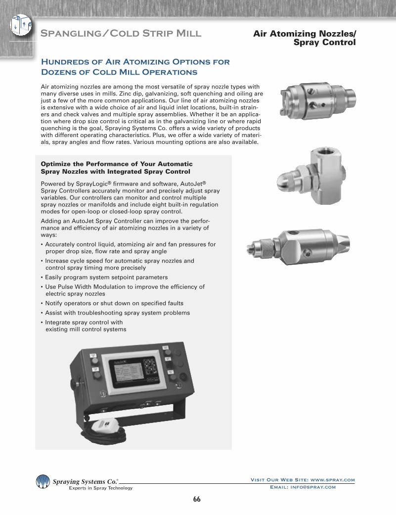
66
������������������������������������������������������
Spangling/Cold Strip Mill
Air atomizing nozzles are among the most versatile of spray nozzle types with many diverse uses in mills. Zinc dip, galvanizing, soft quenching and oiling are just a few of the more common applications. Our line of air atomizing nozzles is extensive with a wide choice of air and liquid inlet locations, built-in strain-ers and check valves and multiple spray assemblies. Whether it be an applica-tion where drop size control is critical as in the galvanizing line or where rapid quenching is the goal, Spraying Systems Co. offers a wide variety of products with different operating characteristics. Plus, we offer a wide variety of materi-als, spray angles and flow rates. Various mounting options are also available.
Optimize the Performance of Your Automatic Spray Nozzles with Integrated Spray Control
Powered by SprayLogic® firmware and software, AutoJet® Spray Controllers accurately monitor and precisely adjust spray variables. Our controllers can monitor and control multiple spray nozzles or manifolds and include eight built-in regulation modes for open-loop or closed-loop spray control.
Adding an AutoJet Spray Controller can improve the perfor-mance and efficiency of air atomizing nozzles in a variety of ways:
• Accurately control liquid, atomizing air and fan pressures for proper drop size, flow rate and spray angle
• Increase cycle speed for automatic spray nozzles and control spray timing more precisely
• Easily program system setpoint parameters
• Use Pulse Width Modulation to improve the efficiency of electric spray nozzles
• Notify operators or shut down on specified faults
• Assist with troubleshooting spray system problems
• Integrate spray control with existing mill control systems
Air Atomizing Nozzles/Spray Control
Hundreds of Air Atomizing Options for Dozens of Cold Mill Operations

6767
������������������������������������������������������
Spangling/Cold Strip Mill
Variable Spray Air Atomizing Options Allow Fine-Tuning of Spray Performance
Our VAU and VMAU Air Atomizing nozzles allow you to adjust the atomizing air, fan air and liquid flow independently. For example, you can reduce the atomizing air to produce a larger drop size. Or, you can adjust the fan air line to regulate the spray pattern and coverage without affecting the drop size or flow rate. Independent con-trol of the liquid flow also allows you to achieve various distribution patterns with the use of just one nozzle. An additional inlet/outlet port allows for liquid recircula-tion that effectively maintains the flow of viscous liquids such as oils.
The VMAU allows for a slightly finer adjustment of the spray for applications requir-ing high precision. It also features a modular design approach for maximum flexibil-ity. Other unique features of the VMAU include:
• O-ring sealed air cap on the fluid tip for positive alignment and sealing
• Patent-pending modular body and threadless fluid tip design
• Available with anti-bearding set-ups
• Use of a baffling system for supplying the atomizing and fan air. This system dis-tributes both the fan and atomizing air equally, providing a more uniform spray pattern.
Current VAU customers can easily change to the VMAU since the centerline distance and mounting thread is the same on both nozzles.
VAU nozzles are available with seven different spray set-ups with flows ranging from 0.74 to 47 gph (2.8 to 179 l/h). For complete performance data, request data sheets 37459-V67B, 37459-V67A, 37459-V67, 37459-V113A, 37459-V113, 37459-128 and 37459-V152.
VMAU nozzles can utilize any of eight different spray set-ups that provide flow rates ranging from 0.74 to 73 gph (2.8 to 276 l/h). The following chart provides liquid capacity data for each of the available set-ups. Refer to the data sheets listed for additional details and spray performance data.
Air Atomizing Nozzles
Ordering Info VMAU Air Atomizing Nozzle
1/4VMAU – 316SS
Model # Material Code
Note: body, actuator and spray set-up must be ordered separately.
SUVM113A – 316SS
Spray Set-up Material Code
Performance – VMAU Nozzles
Spray Set-up NumberLiquid Capacity (Liters per hour)*
Data Sheet Number0.2 1.4
SUVM67A-SS 2.8 7.3 52530-001
SUVM67B-SS 4.2 11.1 52530-002
SUVM67-SS 8.1 21 52530-003
SUVM113A-SS 13.6 35 52530-004
SUVM113-SS 18.4 48 52530-005
SUVM128-SS 40.8 106 52530-006
SUVM152-SS 72 189 52530-007
SUVM189-SS 106 276 52530-008
*At the stated pressure in bar.

68
������������������������������������������������������
Spangling/Cold Strip Mill Air Atomizing Nozzles
Standard Air Atomizing Nozzles
Our J Series of air atomizing nozzles include:
Low-Capacity Series. Our 1/8J and 1/4J models range in capacity from 0.13 to 72 gph (0.49 to 280 l/h).
Medium-Capacity Series. Our 1/2J models range in capacity from 4.1 to 306 gph (15.5 to 1158 l/h).
High-Capacity Series. Our 1J models range in capacity from 24 to 1740 gph (91 to 6586 l/h).
These models are designed to operate at air pressures ranging from 10 to 60 psi (0.7 to 4.0 bar) and can be specified with pressure or siphon/gravity liquid-fed spray set-ups. They are available in an array of body styles and with a variety of options. Material choices include nickel-plated brass, 303 stainless steel, 316 stainless steel along with other machineable materials. All J Series nozzles are available in drip-free versions.
Detailed information on the options and performance of the air atomizing nozzles most commonly used in steel mills can be found in our Industrial Spray Products Catalog or by contacting your local sales representative.
J
• The J basic nozzle assembly features air and liquid inlets in opposite positions with an end plug. 1/8” and 1/4” inlet connections are available.
Standard
• The 1/4JAU features 1/4” NPT (F) air and liquid inlets and 1/8” NPT (F) control valve air inlets.
Single Air Line
• The 6218-1/4JAU features a single air line used both for spray atomization and for operation of the air cylinder. The single air line is regulated at the desired “on/off” cycle time causing simultaneous flow of atomizing air and liquid. The nozzle operates up to 180 cycles per minute and requires a minimum air pressure of 30 psi (2 bar).
1/4 JAUH
• The 1/4JAUH is a compact air actuated automatic spray gun. It can be used with any UniJet® spray tip to provide precise automated control of intermittent spraying.

6969
������������������������������������������������������
Spangling/Cold Strip MillAir Atomizing Nozzles
10535-1/4J, 10536-1/2J, 10537-1J
• The J Series Air Atomizing nozzles mix air and liquid supplied at line pressures up to 125 psi (9 bar) to produce fine atomization. The self-contained air cyl-inder provides controlled “on/off” operation at any desired frequency up to 180 cycles per minute. The J Series features a spray nozzle body assembly that is completely separate from the air cylinder assembly for minimal maintenance and fast, easy cleaning of the nozzle. The TEFLON® packings and gaskets in the nozzle withstand continuous use at temperatures up to 400°F (205°C) and the air cylinder packing is rec-ommended for temperatures up to 150°F (65°C).
Available with 1/4”. 1/2” and 1” inlet connections.
24AUA
• 24AUA Air Atomizing nozzles feature a 1/2” (12.7 mm) diameter mounting hole and locking screw for quick installation and easy positioning on a mounting bar. The shut-off needle and valve seat are available in tungsten carbide or stainless steel. The valve seat is located directly behind the spray tip for drip-free shut off. A rear knob locks the shut-off needle in place to prevent accidental discharge while changing spray tips. The liquid inlet connection is available in the standard down position or one of seven other positions in intervals of 45°.
Cycles/min: 180
Pressure: 4000 psi (280 bar)
Capacity: 0.6 gpm (2.3 l/min)
24AUA-20190• Offering similar features to the standard 24AUA,
this version has an aluminum support body and end cap for a total nozzle weight of 1.25 lbs (0.6 kg). Operating at liquid pressures up to 3000 psi (210 bar), the 24AUA-20190 requires a minimum air pres-sure of 42 psi (3 bar) for the air cylinder.
Cycles/min: 180
Pressure: 3000 psi (210 bar)
Capacity: 0.6 gpm (2.3 l/min)
22AUH
• A 1/2” (12.7 mm) diameter mounting hole and lock-ing screw allows quick installation and positioning of the 22AUH Air Atomizing nozzle on a mounting bar. Constructed of brass with nickel-plated external surfaces, the 22AUH also features a TEFLON® valve seat and packings and stainless steel valve stem. A variety of spray tips are available in flat, hollow cone and full cone spray patterns. The 22AUH is also available with an inlet body and cap assembly of stainless steel.
Cycles/min: 180
Pressure: 600 psi (40 bar)
Capacity: 2 gpm (7.6 l/min)

70
������������������������������������������������������
Spangling/Cold Strip Mill Air Atomizing Nozzles
Performance – Air Atomizing Round Spray Nozzles
Spray Set-up
No.
Spray Set-up
Consists of Fluid and Air
Cap Combin-
ation
Liquid Capacity (liters per hour) and Air Capacity (liters per minute)
Spray DimensionsLiquid Pressure (bar)
0.7 1.5 2 3 4
Air Press. (bar)
l/hr Air (l/min)
Air Press. (bar)
l/hr Air (l/min)
Air Press. (bar)
l/hr Air (l/min)
Air Press. (bar)
l/hr Air (l/min)
Air Press. (bar)
l/hr Air (l/min)
Air (bar)
Liquid (bar)
Spray Angle
Degree A
B (cm)
D (cm)
SU11
Fluid Cap 2050
+ Air Cap 67147
.70 2.5 15.6 1.1 6.4 11.9 1.4 6.4 13.9 2.7 6.2 23 3.5 7.8 28
.85 1.8 19.0 1.4 5.0 15.0 1.7 5.5 16.7 2.8 5.7 25 3.7 7.3 29 .85 .70 13 30 2.7
1.0 1.4 22 1.7 4.1 18.7 2.0 4.5 19.8 3.0 5.2 27 3.9 6.4 33 1.7 1.5 13 33 3.0
— — — 1.8 3.4 20 2.2 3.4 24 3.1 4.7 29 4.2 5.5 38 2.5 2.0 13 36 3.4
— — — 2.0 3.0 23 2.4 3.0 26 3.2 4.3 31 4.5 4.5 43 3.1 3.0 14 39 3.8
— — — 2.1 2.6 25 2.5 2.5 28 3.4 3.9 33 4.6 4.1 45 4.5 4.0 15 44 4.4
— — — 2.2 2.0 27 2.7 2.3 31 3.7 3.0 38 4.8 3.7 47
SU12A
Fluid Cap2050
+Air Cap73160
.70 2.5 18.7 1.4 5.7 27 1.7 6.7 29 2.2 9.2 34 2.8 11.9 39
.85 2.0 22 1.5 5.2 29 1.8 6.4 31 2.5 8.2 39 3.1 11.0 43 .85 .70 12 43 3.7
1.0 1.6 26 1.7 4.8 32 2.0 5.9 34 2.8 7.2 44 3.4 10.1 47 1.5 1.5 13 46 4.0
— — — 1.8 4.3 35 2.1 5.2 37 3.0 6.7 47 3.7 9.2 52 2.4 2.0 13 48 4.3
— — — 2.0 3.9 37 2.2 4.8 40 3.1 6.3 49 3.9 8.4 58 3.0 3.0 13 51 4.6
— — — 2.1 3.4 40 2.4 4.3 43 3.2 5.9 52 4.2 7.6 62 3.9 4.0 15 56 5.2
— — — — — — 2.7 3.6 48 3.4 5.5 55 4.5 6.8 68
SU12
Fluid Cap2850
+Air Cap73160
.85 4.8 21 1.7 8.4 31 2.0 10.7 33 2.7 16.5 37 3.4 20 43
1.1 4.1 27 1.8 7.5 35 2.1 9.8 37 2.8 15.4 38 3.7 18.4 47 1.5 .70 12 48 4.0
1.4 3.4 33 2.0 7.0 37 2.4 8.2 42 3.1 13.6 43 3.9 16.8 50 2.5 1.5 13 51 4.3
1.5 3.1 35 2.2 5.7 44 2.7 6.8 48 3.4 11.8 49 4.2 15.2 55 3.0 2.0 13 53 4.6
1.7 3.0 39 2.5 4.8 49 3.0 5.9 55 3.7 10.4 55 4.5 13.8 60 3.4 3.0 14 56 4.9
1.8 2.9 41 2.8 4.1 54 3.2 5.0 59 3.9 9.1 61 4.8 12.4 65 4.2 4.0 15 60 5.3
2.0 2.8 44 3.1 3.6 59 3.5 4.1 65 4.2 7.9 65 4.9 11.8 68
SU22B
Fluid Cap40100
+Air Cap1401110
1.1 13.0 76 2.2 17.8 116 2.8 20 136 3.4 32 149 4.6 37 193
1.4 8.9 91 2.5 13.1 130 3.1 16.3 149 3.9 25 170 5.3 29 220 1.7 .70 18 66 4.9
1.5 7.2 98 2.8 9.5 143 3.4 11.9 163 4.6 15.9 205 5.6 25 235 2.8 1.5 20 76 6.1
1.7 5.8 105 3.1 7.0 157 3.9 7.0 187 5.3 9.1 240 6.0 21 250 3.9 2.0 20 81 6.7
1.8 4.7 112 3.4 4.9 171 4.2 4.7 205 5.6 6.8 255 6.3 17.4 270 5.3 3.0 21 91 7.9
2.0 3.6 119 3.5 4.2 178 4.6 3.0 220 6.0 5.0 275 6.7 14.0 290 6.0 4.0 21 97 9.1
2.1 2.7 127 — — — — — — 6.3 3.6 290 7.0 11.0 305
SU22
Fluid Cap60100
+Air Cap1401110
.85 31 57 1.4 61 69 2.1 53 96 2.7 80 103 3.8 88 135
1.0 25 66 1.5 54 76 2.4 41 112 3.0 69 117 4.2 73 156 1.0 .70 17 61 4.9
1.1 18.5 75 1.7 48 85 2.7 31 127 3.2 59 130 4.6 61 176 1.8 1.5 18 69 5.8
1.3 12.9 85 1.8 41 93 2.8 26 136 3.5 49 146 4.9 48 196 2.8 2.0 20 76 6.7
— — — 2.0 35 102 3.0 22 144 3.7 44 154 5.3 39 215 3.5 3.0 20 79 7.0
— — — 2.1 30 110 — — — 3.8 37 161 5.6 31 240 4.9 4.0 21 91 8.5
— — — 2.2 25 119 — — — 3.9 35 170 6.0 23 260
SU42
Fluid Cap100150
+Air Cap1891125
1.0 44 86 1.4 125 79 2.0 123 108 2.2 199 88 3.0 250 99
1.1 32 102 1.5 106 91 2.1 108 119 2.5 174 110 3.2 225 120 1.0 .70 19 89 6.1
— — — 1.7 87 105 2.2 95 130 2.8 146 133 3.5 205 141 1.7 1.5 20 99 7.0
— — — 1.8 70 118 2.4 79 143 3.1 121 154 3.8 182 163 2.4 2.0 21 104 7.6
— — — 2.0 55 130 2.5 64 155 3.2 108 166 4.1 159 184 3.1 3.0 21 107 7.9
— — — — — — 2.7 52 166 3.4 95 176 4.6 121 225 3.8 4.0 22 117 9.1
— — — — — — 2.8 42 178 3.5 84 187 4.9 93 255

7171
������������������������������������������������������
Air Atomizing Nozzles Spangling/Cold Strip Mill
Performance – Air Atomizing Wide-Angle Round Spray Nozzles
WIDE ANGLE ROUNDSPRAY PATTERN
Spray Set-up No.
Spray Set-up Consists of Fluid and Air Cap
Combination
Liquid Capacity (liters per hour) and Air Capacity (liters per minute)
Spray DimensionsLiquid Pressure (bar)
0.7 1.5 2 3 4
Air Press. (bar)
l/hr. Air l/min
Air Press. (bar)
l/hr. Air l/min
Air Press. (bar)
l/hr. Air l/min
Air Press. (bar)
l/hr. Air l/min
Air Press. (bar)
l/hr. Air l/min
Air (bar)
Liquid (bar)
A (cm)
B (cm)
C (cm)
D (m)
SU16
Fluid Cap 2050
+ Air Cap
67-6-20-70°
.60 5.3 10.2 1.1 8.1 13.3 1.5 8.1 16.4 2.4 8.9 22 3.1 10.5 24
.70 4.3 12.2 1.3 7.0 15.0 1.8 6.6 21 2.7 8.1 26 3.4 9.7 28 .70 .70 14 18 23 1.5
.85 3.0 14.2 1.4 6.4 17.0 2.1 4.9 25 3.0 6.4 30 3.9 7.8 36 1.4 1.5 15 19 24 1.8
1.0 1.7 17.0 1.5 5.5 19.0 2.4 3.2 29 3.2 4.9 34 4.2 6.1 42 1.8 2.0 16 20 25 2.1
— — — 1.7 4.5 22 — — — 3.4 4.2 37 4.6 4.4 47 3.0 3.0 16 20 26 2.7
— — — 1.8 3.5 24 — — — 3.5 3.4 40 4.9 2.8 54 3.9 4.0 19 23 30 4.0
SU26B
Fluid Cap40100
+Air Cap
140-6-37-70°
.85 7.0 50 1.7 13.2 68 2.0 18.5 68 2.8 25 84 3.7 31 96
1.0 2.1 62 1.8 9.8 79 2.1 15.1 76 3.0 22 92 3.8 28 105 .85 .70 18 24 31 1.8
— — — — — — 2.2 11.7 85 3.1 18.5 101 3.9 26 113 1.7 1.5 19 25 33 2.4
— — — — — — — — — 3.2 15.1 109 4.1 23 122 2.1 2.0 19 25 33 3.2
— — — — — — — — — 3.4 12.1 119 4.2 20 130 3.2 3.0 20 26 34 4.1
— — — — — — — — — 3.5 9.1 130 4.6 13.6 153 4.1 4.0 21 28 37 5.9
— — — — — — — — — 3.7 6.1 142 4.9 6.8 183
SU26
Fluid Cap60100
+Air Cap
140-6-37-70°
.70 24 32 1.4 43 37 2.1 33 66 2.8 52 65 3.7 63 68
.85 13.6 44 1.5 35 49 2.2 26 78 3.0 46 76 3.8 58 79 .85 .70 19 25 36 2.1
1.0 7.6 57 1.7 28 61 2.4 18.9 89 3.1 39 87 3.9 52 101 1.5 1.5 20 27 37 3.2
— — — 1.8 21 71 2.5 11.7 100 3.2 33 99 4.2 41 111 2.4 2.0 20 27 37 4.1
— — — — — — — — — 3.4 26 110 4.6 27 138 3.2 3.0 20 28 38 5.0
— — — — — — — — — 3.5 19.5 122 4.9 15.9 166 3.9 4.0 20 28 39 6.8
— — — — — — — — — 3.7 13.2 133 - - -
SU29
Fluid Cap60100
+Air Cap
140-6-52-70°
1.3 36 85 2.1 57 116 3.1 53 156 4.2 64 197 5.6 74 245
1.5 29 102 2.4 51 130 3.2 50 163 4.9 51 230 6.0 68 260 2.0 .70 20 25 33 5.5
1.8 23 117 2.7 45 143 3.4 47 170 5.6 40 265 6.3 62 280 3.0 1.5 20 27 34 6.4
2.0 19.7 125 3.0 39 157 3.5 45 177 6.0 34 285 6.7 56 295 3.9 2.0 22 28 37 8.2
2.1 16.7 133 3.2 33 170 3.9 38 194 6.3 28 300 7.0 51 315 6.0 3.0 23 29 38 9.1
2.3 14.0 142 3.5 28 185 4.6 25 230 6.7 22 320 - - - 6.3 4.0 24 32 41 10.4
2.4 11.4 149 4.2 13.6 220 4.9 18.5 245 7.0 17.8 335 - - -
SU30
Fluid Cap40100
+Air Cap
120-6-35-60°
1.1 12.3 40 2.2 16.3 62 2.7 21 69 4.2 19.3 100 5.6 22 130
1.3 9.9 45 2.5 12.1 71 3.0 16.3 78 4.6 14.6 113 6.0 17.6 142 1.5 .70 15 19 23 2.7
1.4 7.9 50 2.8 8.9 79 3.2 12.3 86 4.9 10.8 124 6.3 14.0 152 3.0 1.5 16 20 24 4.6
1.5 6.1 54 3.0 7.6 83 3.4 10.7 91 5.3 8.1 135 6.7 11.4 163 3.4 2.0 16 20 24 5.5
1.7 4.9 58 3.1 6.4 87 3.5 9.3 94 5.6 6.2 146 7.0 9.1 174 5.3 3.0 18 22 25 7.3
1.8 3.9 62 3.2 5.5 91 3.9 6.4 105 6.0 4.9 157 — — — 6.3 4.0 19 24 30 9.4
2.0 3.1 67 3.4 4.7 95 4.2 4.7 115 6.3 4.0 167 — — —
SU46
Fluid Cap100150
+Air Cap
189-6-62-70°
1.7 25 156 3.0 39 230 3.4 50 250 4.6 62 320 6.0 93 395
1.8 19.7 167 3.1 33 240 3.5 43 260 4.9 47 345 6.3 77 425 2.0 .70 24 33 46 5.5
2.0 15.1 178 3.2 27 255 3.7 41 275 5.3 36 375 6.7 62 460 3.2 1.5 25 34 47 6.4
2.1 11.4 193 3.4 23 265 3.9 27 300 5.6 26 405 7.0 52 495 3.9 2.0 28 37 51 7.3
2.3 7.6 205 3.5 18.5 280 4.1 23 310 6.0 18.9 435 — — — 5.3 3.0 29 38 53 7.9
— — — 3.7 14.8 290 4.2 18.9 320 6.3 13.6 460 — — — 6.3 4.0 33 42 58 9.8
— — — — — — 4.4 15.9 335 — — — — — —

72
������������������������������������������������������
Spangling/Cold Strip Mill Air Atomizing Nozzles
Performance – Air Atomizing 360˚ Circular Spray Nozzles
Performance – Air Atomizing Deflected Flat Spray Nozzles
Spray Set-up No.
Spray Set-up Consists of Fluid and
Air Cap Combination
Liquid Capacity (liters per hour) and Air Capacity (liters per minute)
Liquid Pressure (bar)
0.7 1.5 2 3 4
Air Press. (bar)
l/hr. Air l/min
Air Press. (bar)
l/hr. Air l/min
Air Press. (bar)
l/hr. Air l/min
Air Press. (bar)
l/hr. Air l/min
Air Press. (bar)
l/hr. Air l/min
SU340C
Fluid Cap 60150
+ Air Cap
189-6-62-160HC
1.4 15.1 69 2.8 19.5 142 3.5 21 185 4.2 48 210 6.0 45 340
1.5 10.6 77 3.0 16.1 153 3.7 17.6 196 4.6 37 240 6.3 37 375
1.7 7.6 84 3.1 13.2 165 3.8 14.8 210 4.9 28 275 6.7 30 405
1.8 5.7 93 3.2 10.6 177 3.9 12.5 220 5.6 15.5 340 7.0 24 440
2.0 4.2 103 3.4 8.3 188 4.2 8.1 245 6.3 7.8 425 — — —
Spray Set-up No.
Spray Set-up Consists of Fluid and Air Cap
Combination
Liquid Capacity (liters per hour) and Air Capacity (liters per minute)
Liquid Pressure (bar)
0.7 1.5 2 3 4
Air Press. (bar)
l/hr. Air l/min
Air Press. (bar)
l/hr. Air l/min
Air Press. (bar)
l/hr. Air l/min
Air Press. (bar)
l/hr. Air l/min
Air Press. (bar)
l/hr. Air l/min
SU240E
Fluid Cap 28150
+ Air Cap
189110-75°
.40 11.0 45 1.1 14.5 79 1.5 15.7 96 2.1 20 114 2.7 26 133
.60 9.5 54 1.3 13.2 86 1.7 14.3 104 2.2 19.2 121 3.2 22 160
.70 7.6 65 1.4 11.8 95 1.8 12.9 112 2.7 15.8 146 3.8 17.7 186
.80 5.7 77 1.5 10.0 103 2.1 9.8 130 3.1 11.8 173 4.4 13.1 230
— — — 1.7 8.7 113 2.2 8.3 142 3.2 10.3 183 4.6 10.2 250

7373
������������������������������������������������������
Air Atomizing Nozzles Spangling/Cold Strip Mill
Performance – Air Atomizing Flat Spray Nozzles
Spray Set-up No.
Spray Set-up Consists of Fluid and
Air Cap Combination
Liquid Capacity (liters per hour) and Air Capacity (liters per minute)
Spray DimensionsLiquid Pressure (bar)
0.7 1.5 2 3 4
Air Press. (bar)
l/hr. Air l/min
Air Press. (bar)
l/hr. Air l/min
Air Press. (bar)
l/hr. Air l/min
Air Press. (bar)
l/hr. Air l/min
Air Press. (bar)
l/hr. Air l/min
Air (bar)
Liquid (bar)
A (cm)
B (cm)
C (cm)
D (m)
SU13A
Fluid Cap 2050
+ Air Cap 73328
.70 5.5 24 1.3 9.1 31 2.0 8.6 42 2.7 11.2 52 3.9 12.0 69
.85 4.7 27 1.5 7.7 36 2.2 7.5 47 3.0 10.1 56 4.6 9.7 81 1.1 .70 25 36 46 2.6
1.0 4.1 31 1.8 6.5 42 2.5 6.2 52 3.2 9.1 62 5.3 7.5 93 2.1 1.5 36 48 66 3.0
1.1 3.5 34 2.1 5.4 47 2.8 5.2 57 3.5 8.1 66 6.0 5.3 104 2.8 2.0 38 53 76 3.2
1.3 3.0 37 2.4 4.3 52 3.1 4.2 63 4.2 5.4 79 6.3 4.3 110 3.5 3.0 47 61 86 3.4
1.4 2.5 40 2.7 3.3 57 3.2 3.7 65 4.6 4.2 85 6.7 3.3 116 6.0 4.0 56 74 94 4.0
1.5 2.0 44 2.8 2.8 60 3.4 3.2 68 4.9 3.1 91 7.0 2.4 122
SU13
Fluid Cap2850
+Air Cap73328
.85 8.2 19.8 1.4 14.4 27 2.1 13.5 36 2.7 19.1 42 4.6 16.1 69
1.0 6.8 23 1.7 11.9 32 2.4 11.4 42 3.0 17.1 46 4.9 13.8 76 1.1 .70 36 46 71 2.1
1.1 5.5 27 2.0 9.5 37 2.7 9.2 47 3.2 15.1 52 5.3 11.5 83 2.1 1.5 43 61 81 2.4
1.3 4.1 30 2.1 8.3 40 3.0 7.1 53 3.5 13.1 57 5.6 9.3 90 3.0 2.0 51 66 89 2.6
1.4 2.9 34 2.2 7.1 43 3.2 5.0 59 4.2 8.1 72 6.0 7.3 97 3.5 3.0 58 76 97 2.7
— — — 2.4 6.1 46 3.4 4.0 63 4.6 5.9 79 6.3 5.6 104 5.6 4.0 58 76 97 3.2
— — — 2.5 5.1 49 3.5 3.3 66 4.9 4.0 86 6.7 4.3 112
SUN13
Fluid Cap2850
+Air Cap73335
1.0 9.0 25 2.0 10.4 41 2.4 11.6 48 3.1 15.6 56 4.2 17.1 73
1.1 7.8 30 2.1 9.3 45 2.5 10.4 51 3.2 14.6 59 4.6 15.0 80 1.4 .70 10 13 17 3.0
1.3 6.6 32 2.2 8.2 48 2.7 9.4 54 3.4 13.7 62 4.9 12.8 87 2.5 1.5 13 15 20 3.7
1.4 5.2 36 2.5 6.1 55 3.0 7.3 61 3.8 10.8 71 5.3 11.0 94 3.2 2.0 13 17 22 4.0
1.7 3.1 44 2.8 4.3 62 3.2 5.5 68 4.2 8.5 82 5.6 9.4 103 3.8 3.0 15 22 28 4.2
2.0 2.0 50 3.1 3.0 69 3.5 4.1 75 4.9 5.2 98 6.3 7.2 119 5.3 4.0 20 25 33 4.8
2.2 1.1 56 3.4 2.0 75 3.8 2.9 81 6.0 2.3 120 7.0 6.1 134
SU14
Fluid Cap2850
+Air Cap73320
1.3 3.9 30 2.1 7.4 40 3.0 6.1 52 3.9 9.4 60 5.3 10.2 78
1.4 3.0 33 2.4 5.3 45 3.1 5.3 54 4.2 7.2 67 5.6 8.3 84 1.5 .70 25 33 46 1.8
1.5 2.3 35 2.5 4.4 47 3.2 4.5 57 4.6 5.3 73 6.0 6.6 89 2.7 1.5 36 51 69 2.0
1.7 1.8 38 2.7 3.7 50 3.4 3.8 59 4.9 3.8 80 6.3 5.1 98 3.2 2.0 58 74 91 2.0
1.8 1.3 41 2.8 3.1 52 3.5 3.2 62 — — — — — — 4.2 3.0 61 74 94 2.1
2.0 .95 44 3.0 2.6 55 3.9 1.8 68 — — — — — — 5.6 4.0 64 76 97 2.3
— — — 3.1 2.1 57 — — — — — — — — —

74
������������������������������������������������������
Spangling/Cold Strip Mill Air Atomizing Nozzles
Performance – Air Atomizing Flat Spray Nozzles
Spray Set-up No.
Spray Set-up Consists of Fluid and
Air Cap Combination
Liquid Capacity (liters per hour) and Air Capacity (liters per minute)
Spray DimensionsLiquid Pressure (bar)
0.7 1.5 2 3 4
Air Press. (bar)
l/hr. Air l/min
Air Press. (bar)
l/hr. Air l/min
Air Press. (bar)
l/hr. Air l/min
Air Press. (bar)
l/hr. Air l/min
Air Press. (bar)
l/hr. Air l/min
Air (bar)
Liquid (bar)
A (cm)
B (cm)
C (cm)
D (m)
SUN23
Fluid Cap60100
+Air Cap125340
1.0 17.0 23 2.0 24 44 2.4 28 51 3.4 38 72 3.9 65 75
1.1 11.0 27 2.1 18.9 50 2.5 23 59 3.5 33 80 4.2 53 89 1.1 .70 10 13 15 2.4
1.3 7.6 33 2.2 14.4 56 2.7 18.9 66 3.7 28 89 4.6 40 108 2.1 1.5 10 13 17 3.0
1.4 3.2 40 2.4 10.6 63 2.8 15.1 74 3.8 23 97 4.9 30 127 2.8 2.0 13 17 22 3.4
— — — 2.5 7.2 71 3.0 11.7 79 3.9 19.7 105 5.3 21 149 3.7 3.0 15 20 28 3.6
— — — — — — — — — 4.2 13.1 120 5.6 13.8 173 4.9 4.0 20 25 35 4.0
— — — — — — — — — 4.6 7.2 138 6.3 3.2 225
SU23B
Fluid Cap40100
+Air Cap125328
1.1 11.2 54 2.1 18.0 79 2.7 19.6 93 3.5 27 112 4.6 33 137
1.3 8.5 60 2.2 15.8 84 2.8 17.3 98 3.7 25 116 4.9 28 149 1.4 .70 15 18 20 3.0
1.4 6.5 65 2.4 13.6 89 3.0 15.2 103 3.8 23 121 5.3 24 161 2.4 1.5 23 28 33 3.2
1.5 5.0 71 2.5 11.6 95 3.1 13.2 109 3.9 21 126 5.6 19.7 174 3.0 2.0 25 33 46 3.4
1.7 3.8 77 — — — 3.2 11.4 114 4.1 18.9 132 6.0 15.7 187 3.7 3.0 30 38 46 3.5
— — — — — — — — — 4.2 17.0 137 6.3 12.4 200 5.3 4.0 33 41 48 4.0
SU23
Fluid Cap60100
+Air Cap125328
.85 27 33 1.8 38 55 2.4 39 67 3.2 58 76 4.6 59 106
1.0 20 38 2.1 28 66 2.7 30 77 3.5 47 87 5.3 40 132 1.1 .70 18 23 30 3.4
1.1 15.9 45 2.2 24 71 3.0 24 87 3.8 38 97 5.6 32 145 2.4 1.5 23 30 41 3.5
1.3 12.5 48 2.4 21 76 3.2 17.8 98 3.9 34 103 6.0 26 158 3.2 2.0 25 33 43 3.7
1.4 10.2 56 2.5 17.8 82 3.4 15.1 103 4.2 27 113 6.3 20 172 3.9 3.0 30 38 48 3.8
1.5 7.6 62 2.7 15.1 87 3.5 12.9 109 4.6 20 126 6.7 15.9 185 6.0 4.0 33 41 51 4.4
— — — — — — 3.7 10.6 114 4.9 14.8 140 7.0 12.7 198
SU43
Fluid Cap100150
+Air Cap189351
1.0 29 90 1.8 56 117 2.1 100 119 3.0 126 140 4.1 140 181
1.1 18.9 108 2.0 40 133 2.2 79 133 3.1 110 151 4.2 125 193 1.0 .70 18 20 25 3.4
— — — — — — 2.4 62 147 3.2 95 163 4.6 89 225 1.8 1.5 25 30 43 3.8
— — — — — — 2.5 48 162 3.4 78 184 4.9 58 265 2.4 2.0 25 30 46 4.3
— — — — — — 2.7 36 177 3.5 62 193 5.3 34 305 3.4 3.0 33 41 53 4.6
— — — — — — — — — 3.7 48 210 5.6 16.7 340 4.9 4.0 36 43 58 5.2
— — — — — — — — — 3.8 37 225 — — —

7575
������������������������������������������������������
Air Atomizing Nozzles Spangling/Cold Strip Mill
Performance – Air Atomizing Flat External Mix Spray Nozzles
Spray Set-up No.
Spray Set-up Consists of Fluid and Air Cap
Combination
Liquid Capacity (liters per hour) and Air Capacity (liters per minute)
Spray DimensionsLiquid Pressure (bar)
0.2 0.3 0.7 1.5 3
Air Press. (bar)
Air l/min l/hr.
Air Press. (bar)
Air l/min l/hr.
Air Press. (bar)
Air l/min l/hr.
Air Press. (bar)
Air l/min l/hr.
Air Press. (bar)
Air l/min l/hr. Air
(bar)Liquid (bar)
A (cm)
B (cm)
C (cm)
D (m)
SUE15B
Fluid Cap 1650
+ Air Cap
67228-45°
.20 25.2 2.8 3.5 26.3 3.5 .70 31.2 5.3 1.4 45.3 7.8 2.8 73.6 11.0 .20 .20 9.0 15.0 23 .90
.35 26.3 2.8 .70 31.2 3.5 1.05 39.6 5.3 1.75 53.8 7.8 3.5 85 11.0 1.05 .20 9.0 15.0 23 1.2
.70 31.2 2.8 1.05 39.6 3.5 1.4 45.3 5.3 2.1 59.5 7.8 4.2 102 11.0 1.4 .35 10.0 15.0 23 1.2
1.05 39.6 2.8 1.4 45.3 3.5 1.75 53.8 5.3 2.8 73.6 7.8 4.9 119 11.0 1.4 1.4 11.5 18.0 25 1.5
1.4 45.3 2.8 1.75 53.8 3.5 2.1 59.4 5.3 3.5 85 7.8 5.3 127.5 11.0 1.75 .70 11.5 15.0 24 1.5
1.75 53.8 2.8 2.1 59.4 3.5 2.8 73.6 5.3 4.2 102 7.8 5.6 139 11.0 2.8 1.4 13.0 18.0 28 1.8
2.1 59.4 2.8 2.8 73.6 3.5 3.5 85 5.3 5.6 139 7.8 6.3 159 11.0 4.9 2.8 15.0 18.0 24 2.4
SUE18B
Fluid Cap1650
+Air Cap
62240-60°
.35 22 2.8 .35 22 3.5 .40 25 5.3 .60 28 7.8 .70 34 11.0 .60 .70 23 30 40 1.8
.40 25 2.8 .40 25 3.5 .60 28 5.3 .70 34 7.8 1.1 45 11.0 .60 1.5 28 35 46 1.8
.50 27.5 2.8 .60 28 3.5 .70 34 5.3 1.1 45 7.8 1.8 62 11.0 1.4 1.5 25 30 41 2.7
.60 28 2.8 .70 34 3.5 .85 40 5.3 1.4 54 7.8 2.5 79 11.0 1.1 2.0 28 35 48 2.6
SUE15A
Fluid Cap2050
+Air Cap
67228-45°
.35 26.3 4.5 .70 31.2 5.5 1.05 39.6 8.3 1.75 53.8 12.2 3.15 82 16.6 .35 .20 7.5 14.0 22 1.0
.70 31.2 4.5 1.05 39.6 5.5 1.4 45.3 8.3 2.1 59.4 12.2 3.5 85 16.6 1.4 .20 9.0 15.0 22 1.7
1.05 39.6 4.5 1.4 45.3 5.5 1.75 53.8 8.3 2.8 73.6 12.2 4.2 102 16.6 1.75 .35 10.0 16.5 23 1.8
1.4 45.3 4.5 1.75 53.8 5.5 2.1 59.4 8.3 3.5 85 12.2 4.9 119 16.6 1.75 1.4 13.0 19.0 29 2.1
1.75 53.8 4.5 2.1 59.4 5.5 2.8 73.6 8.3 4.2 102 12.2 5.25 127 16.6 2.1 .70 13.0 18.0 25 1.8
2.1 59.4 4.5 2.8 73.6 5.5 3.5 85 8.3 4.9 119 12.2 6.3 159 16.6 3.5 1.4 13.0 22 30 2.4
2.8 73.6 4.5 3.5 85 5.5 4.2 102 8.3 6.3 159 12.2 6.7 164 16.6 5.3 2.8 15.0 19.0 25 3.0
SUE18A
Fluid Cap2050
+Air Cap
62240-60°
.35 22 4.5 .35 22 5.5 .60 28 8.3 .70 34 12.2 1.1 45 16.6 1.1 .70 30 38 48 2.1
.60 28 4.5 .70 34 5.5 .70 34 8.3 1.4 54 12.2 1.4 54 16.6 .70 1.5 38 46 58 1.8
.70 34 4.5 1.1 45 5.5 1.4 54 8.3 2.1 71 12.2 2.1 71 16.6 2.5 1.5 33 40 51 3.0
1.1 45 4.5 1.4 54 5.5 2.1 71 8.3 2.5 79 12.2 2.5 79 16.6 1.8 2.0 38 46 58 2.7
SUE15
Fluid Cap2850
+Air Cap
67228-45°
.70 31.2 8.5 1.05 39.6 10.4 1.4 45.3 15.9 2.5 68 23 3.5 85 33 .70 .20 13.0 16.5 25 1.2
1.05 39.6 8.5 1.4 45.3 10.4 1.75 53.8 15.9 2.8 73.6 23 4.2 102 33 1.75 .20 13.0 16.5 25 1.8
1.4 45.3 8.5 1.75 53.8 10.4 2.1 59.4 15.9 3.5 85 23 4.9 119 33 2.1 .35 13.0 18.0 24 1.8
1.75 53.8 8.5 2.1 59.4 10.4 2.8 73.6 15.9 4.2 102 23 5.3 127 33 2.5 1.4 14.0 20 32 1.8
2.1 59.4 8.5 2.8 73.6 10.4 3.5 85.0 15.9 4.9 119 23 5.6 139 33 2.8 .70 14.0 19.0 30 2.3
2.8 73.6 8.5 3.5 85 10.4 4.2 102 15.9 5.6 139 23 6.3 159 33 4.2 1.4 14.0 20 36 3.0
3.5 85 8.5 4.2 102 10.4 4.9 119 15.9 6.3 159 23 7.0 176 33 5.3 2.8 16.5 20 30 4.0
SUE18
Fluid Cap2850
+Air Cap
62240-60°
.40 25 8.5 .40 25 10.4 .40 25 15.9 .70 34 23 1.4 54 33 .60 .70 35 48 63 1.5
.50 27.5 8.5 .60 28 10.4 .60 28 15.9 .85 40 23 1.8 62 33 .70 1.5 38 48 63 1.8
.60 28 8.5 .65 31 10.4 .70 34 15.9 1.1 45 23 2.1 71 33 1.4 1.5 43 53 66 2.4
.70 34 8.5 .70 34 10.4 .85 40 15.9 1.4 54 23 2.5 79 33 1.8 2.0 41 51 69 2.7

76
������������������������������������������������������
Spangling/Cold Strip Mill Air Atomizing Nozzles
Performance – Air Atomizing Flat External Mix Spray Nozzles
Spray Set-up No.
Spray Set-up Consists of Fluid and Air Cap
Combination
Liquid Capacity (liters per hour) and Air Capacity (liters per minute)
Spray DimensionsLiquid Pressure (bar)
0.2 0.3 0.7 1.5 3
Air Press. (bar)
Air l/min l/hr.
Air Press. (bar)
Air l/min l/hr.
Air Press. (bar)
Air l/min l/hr.
Air Press. (bar)
Air l/min l/hr.
Air Press. (bar)
Air l/min l/hr. Air
(bar)Liquid (bar)
A (cm)
B (cm)
C (cm)
D (m)
SUE25B
Fluid Cap 35100
+ Air Cap
134255-45°
.70 85 13.4 1.0 102 16.4 1.4 116 25 2.5 178 37 3.2 212 52 .70 .20 13.0 19.0 25 1.7
1.0 102 13.4 1.4 116 16.4 1.8 139 25 2.8 195 37 3.5 232 52 1.8 .20 13.0 19.0 25 2.7
1.4 116 13.4 1.8 139 16.4 2.1 156 25 3.5 227 37 3.9 255 52 2.1 .35 15.0 19.0 28 3.0
1.8 139 13.4 2.1 156 16.4 2.5 178 25 4.2 266 37 4.2 275 52 2.5 .70 15.0 22 28 3.5
2.1 156 13.4 2.8 195 16.4 2.8 195 25 4.9 312 37 4.9 314 52 2.5 1.4 16.5 23 36 3.7
2.8 195 13.4 3.5 227 16.4 3.5 227 25 5.6 360 37 5.6 360 52 4.2 1.4 16.5 23 37 4.3
3.5 227 13.4 4.2 266 16.4 4.2 266 25 6.3 411 37 6.3 411 52 4.9 2.8 16.5 22 32 4.9
SUE28B
Fluid Cap35100
+Air Cap
122281-60°
.60 91 13.4 .70 102 16.4 1.4 156 25 2.1 210 37 3.2 285 52 2.1 .70 33 40 56 4.3
.70 102 13.4 1.1 130 16.4 2.1 210 25 2.8 260 37 4.2 360 52 2.1 1.5 35 46 58 4.0
1.1 130 13.4 1.8 184 16.4 2.5 235 25 3.5 310 37 5.3 430 52 4.2 1.5 38 48 64 5.2
1.4 156 13.4 2.1 210 16.4 2.8 260 25 4.2 360 37 5.6 455 52 3.9 2.0 41 51 69 4.6
SUE25A
Fluid Cap40100
+Air Cap
134255-45°
.70 85 17.6 1.4 116 22 1.8 139 33 2.8 195 48 3.5 232 68 .70 .35 15.0 19.0 27 2.1
1.0 102 17.6 1.8 139 22 2.1 156 33 3.2 212 48 4.2 275 68 1.8 .70 15.0 19.0 27 3.0
1.4 116 17.6 2.1 156 22 2.5 178 33 3.5 227 48 4.9 314 68 2.5 1.4 15.0 22 33 3.4
1.8 139 17.6 2.5 178 22 2.8 195 33 4.2 266 48 5.3 340 68 2.8 1.4 15.0 22 36 3.8
2.1 156 17.6 2.8 195 22 3.5 227 33 4.9 312 48 5.6 360 68 2.8 1.4 16.5 25 37 4.0
2.8 195 17.6 3.5 227 22 4.2 266 33 5.6 360 48 6.3 411 68 4.2 2.1 16.5 25 37 4.9
3.5 227 17.6 4.2 266 22 4.9 312 33 6.3 411 48 6.6 428 68 5.3 2.8 18.0 23 36 5.8
SUE28A
Fluid Cap40100
+Air Cap
122281-60°
.60 91 17.6 .70 102 22 1.1 130 33 2.5 235 48 3.5 310 68 1.8 .70 35 48 64 3.0
1.1 130 17.6 1.4 156 22 1.8 184 33 3.2 285 48 4.6 380 68 2.5 1.5 38 46 64 3.8
1.4 156 17.6 1.8 184 22 2.5 235 33 3.9 330 48 6.0 475 68 4.2 1.5 30 43 58 4.9
1.8 184 17.6 2.1 210 22 2.8 260 33 4.2 360 48 6.7 525 68 4.2 2.0 33 43 61 5.2
SUE28
Fluid Cap60100
+Air Cap
122281-60°
.70 102 36 1.1 130 45 1.8 184 68 3.2 285 100 5.3 430 141 2.8 .70 46 58 81 4.0
1.1 130 36 1.4 156 45 2.1 210 68 3.5 310 100 6.0 475 141 3.2 1.5 48 58 79 4.3
1.4 156 36 2.1 210 45 2.8 260 68 4.9 405 100 6.7 525 141 5.6 1.5 38 51 66 5.8
1.8 184 36 2.5 235 45 3.2 285 68 5.9 455 100 7.0 550 141 3.9 2.0 48 64 84 4.3
SUE25
Fluid Cap60100
+Air Cap
134255-45°
1.0 102 36 1.8 139 45 2.5 178 68 3.2 212 100 3.9 255 141 1.0 .20 15.0 20 25 2.7
1.4 116 36 2.1 156 45 2.8 195 68 3.5 227 100 4.2 275 141 2.1 .20 15.0 22 29 3.0
1.8 139 36 2.5 178 45 3.2 212 68 3.9 246 100 4.6 297 141 2.8 .35 18.0 24 36 3.5
2.1 156 36 2.8 195 45 3.5 227 68 4.2 266 100 4.9 314 141 3.2 1.4 20 28 39 3.7
2.5 178 36 3.2 212 45 4.2 266 68 4.9 312 100 5.6 360 141 3.5 .70 19.0 27 38 4.0
2.8 195 36 3.5 227 45 4.9 312 68 5.6 360 100 6.3 411 141 4.2 1.4 20 28 39 4.3
3.5 227 36 4.2 266 45 5.6 360 68 6.3 411 100 7.0 453 141 5.6 2.8 18.0 24 38 5.9
SUE45B
Fluid Cap60150
+Air Cap
200278-45°
1.8 235 36 1.8 235 45 2.5 300 68 3.9 410 100 — — — 1.8 .20 15.0 20 29 3.0
2.1 260 36 2.1 260 45 2.8 330 68 4.2 445 100 — — — 2.8 .20 15.0 20 30 3.4
2.5 300 36 2.5 300 45 3.2 355 68 4.6 480 100 — — — 2.8 .30 15.0 20 30 4.0
2.8 330 36 2.8 330 45 3.5 380 68 4.9 529 100 — — — 3.5 .70 17.0 22 32 4.3
3.2 355 36 3.2 355 45 3.9 410 68 5.3 565 100 — — — 3.9 1.5 17.0 22 34 4.6
3.5 380 36 3.5 380 45 4.2 445 68 5.6 600 100 — — — 4.2 1.0 17.0 23 33 4.7
4.2 445 36 4.2 445 45 4.9 520 68 6.3 685 100 — — — 4.9 1.5 17.0 23 34 5.5

7777
������������������������������������������������������
Air Atomizing Nozzles Spangling/Cold Strip Mill
Performance – Air Atomizing Flat External Mix Spray Nozzles
Spray Set-up No.
Spray Set-up Consists of Fluid and Air Cap
Combination
Liquid Capacity (liters per hour) and Air Capacity (liters per minute)
Spray DimensionsLiquid Pressure (bar)
0.2 0.3 0.7 1.5 3
Air Press. (bar)
Air l/min l/hr.
Air Press. (bar)
Air l/min l/hr.
Air Press. (bar)
Air l/min l/hr.
Air Press. (bar)
Air l/min l/hr.
Air Press. (bar)
Air l/min l/hr. Air
(bar)Liquid (bar)
A (cm)
B (cm)
C (cm)
D (m)
SUE45A
Fluid Cap80150
+Air Cap
200278-45°
2.1 260 64 2.8 330 78 3.9 410 119 4.9 520 175 — — — 2.1 .20 17.0 24 34 3.5
2.5 300 64 3.2 355 78 4.2 445 119 5.3 565 175 — — — 3.2 .20 18.0 24 36 4.3
2.8 330 64 3.5 380 78 4.6 480 119 5.6 600 175 — — — 3.9 .30 18.0 25 36 4.9
3.2 355 64 3.9 410 78 4.9 520 119 6.0 640 175 — — — 4.9 .70 18.0 25 36 5.5
3.5 380 64 4.2 445 78 5.3 565 119 6.3 685 175 — — — 4.9 1.5 20 25 38 5.5
4.2 445 64 4.9 520 78 5.6 600 119 — — 175 — — — 5.3 1.0 18.0 25 38 5.8
4.9 520 64 5.6 600 78 6.3 685 119 — — 175 — — — 5.6 1.5 20 25 38 6.1
SUE45
Fluid Cap100150
+Air Cap
200278-45°
2.8 330 102 3.5 380 125 4.6 480 192 5.6 600 280 — — — 2.8 .20 19.0 25 36 4.6
3.2 355 102 3.9 410 125 4.9 520 192 6.0 640 280 — — — 3.9 .20 20 25 37 4.9
3.5 380 102 4.2 445 125 5.3 565 192 6.3 685 280 — — — 4.6 .30 20 25 37 5.2
3.9 410 102 4.6 480 125 5.6 600 192 — — 280 — — — 5.3 .70 22 27 38 5.5
4.2 445 102 4.9 520 125 6.0 640 192 — — 280 — — — 5.6 1.0 22 27 41 5.5
4.6 480 102 5.3 565 125 6.3 685 192 — — 280 — — — 5.6 1.5 22 27 41 5.8
4.9 520 102 5.6 600 125 — — 192 — — 280 — — — 6.0 1.5 22 27 41 6.1

78
������������������������������������������������������
Whether you’re looking for hydraulic spray nozzles for dust control or gas cool-ing, energy-efficient air atomizing nozzles for evaporative cooling or a fully auto-mated system for gas conditioning, you’ll find we have a wide assortment of proven solutions.
WhirlJet and SpiralJet® Nozzles – Ideal for Dust Absorption and Gas Cooling
Standard WhirlJet spray nozzles feature a hollow cone spray pattern with a ring-shaped impact area. They produce a uniform distribution of small- to medium-sized drops over a wide range of flow rates and pressures and are well-suited to pollution control applications in mills that require good atomization of liquids at lower pressures, quick heat transfer or effective airborne drop impingement. WhirlJet nozzles also feature large and unobstructed flow passages, which minimize or elimi-nate clogging.
Specifications:
• Model A and B WhirlJet spray nozzles have removable caps and the original WhirlJet whirlchamber design
• Model AX and BX WhirlJet spray nozzles feature the same uniform spray dis-tribution and two-piece construction as the A and B Series plus a slope-bottom design which reduces the “drilling effect” of the fluid vortex in the whirlcham-ber
• Model C and D WhirlJet spray nozzles feature one-piece cast construction with a precision-machined finish and the original WhirlJet whirlchamber design for uniform spray distribution
• Model CX slope-bottom WhirlJet nozzles feature the same uniform spray per-formance as the C Series, plus the added advantage of the patented, longer-life, slope-bottom design to reduce the “drilling effect” of the liquid vortex in the whirlchamber
• Model CRC two-piece WhirlJet spray nozzles feature a hollow cone spray pat-tern with a ring-shaped impact area. They are available in two spray angle series: narrow angle 45° to 52° and standard angle 60° to 86° with flow rate of 140 gpm at 7 psi (530 l/min at .5 bar)
Dust Control/Gas Cooling
Effective Dust Control and Gas Conditioning Depends on Drop Size… And We Have the Systems, Nozzles and Data You Need

7979
������������������������������������������������������
Dust Control/Gas Cooling
SpiralJet nozzles are also widely used in dust control and gas cooling. Choose from three types: BSJ, HHSJ or HHSJX SpiralJets.
Similar to WhirtlJet® nozzles, BSJ SpiralJet nozzles produce a hollow cone spray pattern. These compact nozzles permit maximum liquid output for a given pipe size and the free passage design minimizes clogging.
BSJ Specifications:
• Spray angles: 50° to an extra wide angle of 180°
• Materials: Brass, 316 stainless steel, PVC or TEFLON®
• Brass nozzles have hex or flats design depending on connection size
• Stainless steel nozzles have hex or flats design depending on capacity size
• PVC and TEFLON® nozzles have rounded design
• Designed with precision impact blade angles that distribute the spray drops for excellent coverage
• Flanged versions available in reaction-bonded silicon carbide
• Custom-sized for your installation and available in several abrasion-resistant materials
HHSJ SpiralJet nozzles produce a full cone spray pattern. Similar to our hollow cone SpiralJet nozzles, the HHSJ nozzles permit maximum liquid output for a given pipe size and feature a clog-resistant free passage design.
HHSJ Specifications:
• 3” and 4” sizes are available in brass and stainless steel
• Brass version is available with hex design. Stainless steel nozzles are available with flats
• TEFLON® and PVC nozzles have a rounded design
HHSJX Specifications:
HHSJX Extra Large Free Passage SpiralJet nozzles minimize the possibility of plug-ging in high-flow pollution control applications. With a simple one-piece design, the inlet orifice is the smallest opening that liquid passes through. The outlet helix orifice is proportionately larger than the inlet opening. This virtually eliminates plugging and allows for maximum liquid output.
• Standard materials: Brass, cast 316 stainless steel, PVC and polypropylene
• Additional materials available upon request: TEFLON®, silicon carbide, Stellite®, Hastelloy® C and ceramic
• Spray Angles: 90° or 120° with full cone spray patterns
• HHSJX nozzle is available in threaded/hex, threaded/round and threaded/flats

80
������������������������������������������������������
Performance — WhirlJet Nozzles
Dust Control/Gas Cooling
Nozzle Inlet
Conn. NPT or BSPT (in.)
Nozzle TypeCapa-
city Size
Inlet Dia. Nom. (mm)
Orifice Dia.
Nom. (mm)
Capacity (Liters per minute)* Spray Angle Degree*
A AX B BX 0.2 0.5 1 1.5 2 3 4 5 6 7 0.5 1.5 6
1/8
● ● ● ● .5 .79 1.2 — .16 .23 .28 .32 .39 .46 .51 .56 .60 — 58 69
● ● ● ● 1 1.6 1.6 — .32 .46 .56 .64 .79 .91 1.0 1.1 1.2 — 64 76
● ● ● ● 2 2.0 2.0 — .64 .91 1.1 1.3 1.6 1.8 2.0 2.2 2.4 52 61 69
● ● ● ● 3 2.4 2.4 — .97 1.4 1.7 1.9 2.4 2.7 3.1 3.3 3.6 52 64 77
● ● ● ● 5 3.2 3.2 1.0 1.6 2.3 2.8 3.2 3.9 4.6 5.1 5.6 6.0 56 67 76
● ● ● ● 8 4.0 4.0 1.6 2.6 3.6 4.5 5.2 6.3 7.3 8.2 8.9 9.6 56 65 70
● ● ● ● 10 4.4 4.4 2.0 3.2 4.6 5.6 6.4 7.9 9.1 10.2 11.2 12.1 55 65 72
1/4
● ● ● ● 1 1.6 1.6 — — .38 .45 .53 .64 .76 .90 1.0 1.2 — 53 67
● ● ● ● 2 2.0 2.0 — — .76 .95 1.0 1.3 1.5 1.8 2.1 2.4 — 62 71
● ● ● ● 3 2.4 2.4 — .79 1.1 1.9 1.6 2.0 2.3 2.8 3.2 3.6 51 65 78
● ● ● ● 5 3.6 3.6 1.0 1.3 1.9 2.3 2.6 3.3 3.8 4.5 5.3 6.1 63 73 79
● ● ● ● 8 4.0 4.0 1.7 2.1 3.0 3.7 4.2 5.3 6.1 7.6 8.7 9.5 61 69 73
● ● ● ● 10 4.8 4.4 2.1 2.7 3.8 4.5 5.3 6.4 7.6 9.5 10.6 12.1 63 70 74
● ● ● ● 15 5.9 5.2 3.1 4.2 5.7 6.8 7.9 9.8 11.4 14 15.9 17.8 63 71 72
3/8
● ● ● ● 5 3.6 3.2 1.0 1.6 2.3 2.8 3.2 3.9 4.6 5.1 5.6 6.0 64 73 79
● ● ● ● 8 4.4 4.0 1.6 2.6 3.6 4.5 5.2 6.3 7.3 8.2 8.9 9.6 62 70 74
● ● ● ● 10 5.2 4.4 2.0 3.2 4.6 5.6 6.4 7.9 9.1 10.2 11.2 12.1 64 72 75
● ● ● ● 15 5.9 5.6 3.1 4.8 6.8 8.4 9.7 11.8 13.7 15.3 16.7 18.1 64 72 74
● ● ● ● 20 7.1 6.4 4.1 6.4 9.1 11.2 12.9 15.8 18.2 20 22 24 63 70 74
● ● ● ● 25 7.5 7.5 5.1 8.1 11.4 14.0 16.1 19.7 23 25 28 30 63 70 74
● ● ● ● 30 8.3 7.9 6.1 9.7 13.7 16.7 19.3 24 27 31 33 36 63 70 74
● ● 15-30.1 5.9 7.9 4.7 7.4 10.5 12.8 14.8 18.2 21 23 26 28 40 50 54
● ● 25-30.1 7.5 7.9 5.7 9.0 12.8 15.6 18 22 26 29 31 34 40 47 51
● ● 50-50.1 8.7 9.5 10.2 16.1 23 28 32 39 46 51 56 60 40 47 50
● ● 50-50.3 8.7 9.5 10.2 16.1 23 28 32 39 46 51 56 60 72 76 78
1/2
● ● ● ● 25 9.5 6.4 5.1 8.1 11.4 14 16.1 19.7 23 25 28 30 63 66 71
● ● ● ● 30 9.5 7.5 6.1 9.7 13.7 16.7 19.3 24 27 31 33 36 67 71 75
● ● ● ● 40 9.5 9.1 8.2 12.9 18.2 22 26 32 36 41 45 48 72 76 78
● ● ● ● 50 9.5 11.1 10.2 16.1 23 28 32 39 46 51 56 60 74 79 82
● ● ● ● 60 9.5 13.1 12.2 19.3 27 33 39 47 55 61 67 72 77 82 86
3/4
● ● ● ● 40 12.7 7.9 8.2 12.9 18.2 22 26 32 36 41 45 48 70 73 74
● ● ● ● 50 12.7 9.5 10.2 16.1 23 28 32 39 46 51 56 60 72 75 77
● ● ● ● 60 12.7 11.1 12.2 19.3 27 33 39 47 55 61 67 72 74 76 79
● ● ● ● 70 12.7 12.7 14.3 23 32 39 45 55 64 71 78 84 76 79 83
● ● ● ● 80 12.7 14.3 16.3 26 36 45 52 63 73 82 89 96 78 82 84
● ● ● ● 90 12.7 14.7 18.3 29 41 50 58 71 82 92 100 109 81 84 84
● ● ● ● 100 12.7 15.9 20 32 46 56 64 79 91 102 112 121 83 86 86
● ● ● ● 110 12.7 17.1 22 35 50 61 71 87 100 112 123 133 85 88 88
● ● ● ● 120 12.7 18.3 24 39 55 67 77 95 109 122 134 145 87 90 90
*At the stated pressure in bar.

8181
������������������������������������������������������
Performance — WhirlJet CX, C, D Nozzles
Dust Control/Gas Cooling
Nozzle Inlet
Conn. NPT or BSPT (in.)
Nozzle TypeCapa-
city Size
Inlet Dia.
Nom. (mm)
Orifice Dia.
Nom. (mm)
Capacity (Liters per minute)* Spray Angle Degree*
CX C D 0.2 0.3 0.5 0.7 1 1.5 2 3 4 5 6 7 0.7 1.5 4
1/2
● 3 11.1 7.5 7.3 9.0 11.6 13.7 16.3 20 23 28 33 37 40 43 60 63 65
● 4 11.1 9.5 9.7 11.9 15.4 18.2 22 27 31 38 44 49 53 58 68 71 73
● 5 11.1 11.5 12.2 14.9 19.3 23 27 33 39 47 54 61 66 72 74 77 80
● 7 11.1 13.5 17.1 21 27 32 38 47 54 66 76 85 93 101 77 80 83
● 3 11.1 7.9 7.3 9.0 11.6 13.7 16.3 20 23 28 33 37 40 43 62 65 67
● 4 11.1 9.9 9.7 11.9 15.4 18.2 22 27 31 38 44 49 53 58 68 71 73
● 5 11.1 11.9 12.2 14.9 19.3 23 27 33 39 47 54 61 66 72 74 77 80
● 7 11.1 13.9 17.1 21 27 32 38 47 54 66 76 85 93 101 77 80 83
3/4
● ● ● 5 15.1 9.9 12.2 14.9 19.3 23 27 33 39 47 54 61 66 72 59 61 63
● ● ● 6 15.1 11.5 14.6 17.9 23 27 33 40 46 57 65 73 80 86 62 64 66
● ● ● 7 15.1 12.7 17.1 21 27 32 38 47 54 66 76 85 93 101 70 71 72
● ● ● 10 15.1 16.7 24 30 39 46 54 67 77 94 109 122 133 144 73 75 77
1
● 7 17.5 11.5 17.1 21 27 32 38 47 54 66 76 85 93 101 64 65 66
● 8 17.5 12.7 19.5 24 31 36 44 53 62 75 87 97 107 115 65 66 67
● 9 17.5 14.3 22 27 35 41 49 60 69 85 98 110 120 130 66 67 69
● 10 17.5 15.5 24 30 39 46 54 67 77 94 109 122 133 144 67 69 71
● 12 17.5 17.1 29 36 46 55 65 80 92 113 131 146 160 173 70 73 75
● 15 17.5 20.6 37 45 58 68 82 100 116 142 163 183 200 215 76 79 81
1-1/4
● 10 21.4 14.3 24 30 39 46 54 67 77 94 109 122 133 144 65 67 67
● 12 21.4 16.3 29 36 46 55 65 80 92 113 131 146 160 173 68 70 71
● 14 21.4 18.3 34 42 54 64 76 93 108 132 153 171 187 200 71 73 75
● 16 21.4 20.2 39 48 62 73 87 107 123 151 174 195 215 230 74 75 77
● 20 21.4 24.2 49 60 77 91 109 133 154 189 220 245 265 290 76 77 79
1-1/2
● 16 27.8 17.5 39 48 62 73 87 107 123 151 174 195 215 230 64 67 69
● 20 27.8 21.8 49 60 77 91 109 133 154 189 220 245 265 290 69 72 74
● 25 27.8 25.8 61 75 96 114 136 167 193 235 270 305 335 360 72 74 76
● 30 27.8 28.6 73 90 116 137 163 200 230 285 325 365 400 430 74 76 78
2
● 30 36.5 23.8 73 90 116 137 163 200 230 285 325 365 400 430 66 67 70
● 35 36.5 27 85 104 135 160 191 235 270 330 380 425 465 500 68 70 73
● 40 36.5 30.2 97 119 154 182 220 265 310 375 435 490 530 580 70 72 75
● 45 36.5 32.9 110 134 173 205 245 300 345 425 490 550 600 650 72 74 78
● 50 36.5 36.1 122 149 193 230 270 335 385 470 540 610 670 720 74 77 82
● 60 36.5 39.7 146 179 230 275 325 400 460 570 650 730 800 860 77 79 84
2-1/2
● 60 47.6 36.1 146 179 230 275 325 400 460 570 650 730 800 860 67 68 71
70 47.6 40.5 171 210 270 320 380 465 540 660 760 850 930 1010 69 71 74
80 47.6 44.1 195 240 310 365 435 535 620 750 870 970 1070 1150 71 73 77
90 47.6 47.6 220 270 345 410 490 600 690 850 980 1100 1200 1300 73 75 80
100 47.6 50.8 245 300 385 455 540 670 770 940 1090 1220 1330 1440 77 79 83
*At the stated pressure in bar.

82
������������������������������������������������������
Dimensions — WhirlJet Nozzles
Materials — WhirlJet Nozzles Ordering Info
WhirlJet Spray Nozzle
1/4 A — SS 10
Inlet Nozzle Material Capacity Conn. Type Code Size
Based on largest/heaviest version of each type.
Material MaterialNozzle
A AX B BX C CX D
Brass (none) ● ● ● ● ●
Mild Steel I ● ● ● ●
303 Stainless Steel SS ● ● ● ●
316 Stainless Steel 316SS ● ● ● ●
Polyvinyl Chloride PVC ● ●
Cast: Iron I ● ● ●
Cast: Brass (none) ● ●
Cast: 316 Stainless Steel SS ● ●
Dust Control/Gas Cooling
Other materials availbale upon request.
Nozzle Type (Conn.)Inlet
Conn. (in.)
A (in.) A(mm) B (in.) B
(mm) C (in.) C(mm) D (in.) D
(mm) L (in.) L(mm)
Net Weight
(oz.)
Net Weight
(kg)
�
�
�
��
A, AX (F)
1/8 11/16 17.5 5/8 16.0 15/32” 12.0 25/32 20 1 25.5 1-1/2 .04
1/4 7/8 22.5 3/4 19.0 17/32” 13.5 29/32 23 1-1/4 32 2-3/4 .08
3/8 1-1/32 26.5 7/8 22.5 11/16” 17.5 1-1/8 28.5 1-15/32 37.5 4-1/4 .12
1/2 1-3/8 35 1-1/8 28.5 27/32” 21.5 1-13/32 36 1-15/16 49.5 8-3/4 .25
3/4 1-9/16 40 1-1/4 32 15/16 24 1-9/16 40 2-3/16 55.5 11 .31
B, BX(M)
1/8 7/8 22.5 5/8 16.0 15/32” 12.0 25/32 20 1-3/16 30.5 1-1/2 .04
1/4 1 25.5 3/4 19.0 17/32 13.5 29/32 23 1-3/8 35 2-1/2 .07
3/8 1-1/8 28.5 7/8 22.5 11/16 17.5 1-1/8 28.5 1-9/16 40 4 .11
1/2 1-3/8 35 1-1/8 28.5 27/32 21.5 1-13/32 36 1-15/16 49.5 7 .20
3/4 1-5/8 41.5 1-1/4 32 15/16 24 1-9/16 40 2-1/4 57.5 10-3/4 .31
C (F)
1/2 1-5/16 33.5 1-5/16 33.5 7/32 5.5 23/32 18.5 1-7/8 48 4-1/2 .13
3/4 1-1/2 38 1-21/32 42 19/64 7.5 29/32 23 2-9/32 58 7 .20
��
��
�CX (F)
1 1-3/4 44.5 1-27/32 47 11/32 9.0 1-1/32 26 2-5/8 66.5 11 .31
1-1/4 2-1/16 50.9 2-3/16 55.6 7/16 11.1 1-1/4 31.7 3-1/16 77.8 20 .57
1-1/2 2-7/16 61.9 2-7/8 73 9/16 14.3 1-21/32 42.1 3-11/16 93.6 28 .79
2 2-15/16 74.6 3-11/16 93.6 23/32 18.2 2-3/32 53.1 4-17/32 115.1 48 1.4
2-1/2 3-1/2 88.9 4-1/2 114.3 15/16 23.8 2-11/16 68.3 5-17/32 140.5 68 1.9
D(M)
1/2 1-3/4 44.5 1-5/16 33.5 1/4 6.5 23/32 18.5 2-5/16 59 5 .14
3/4 2 51 1-21/32 42 5/16 8.0 15/16 24 2-23/32 69 7-1/2 .21

8383
������������������������������������������������������
Performance — SpiralJet BSJ Nozzles
** For all 1/4 and 3/8 connection size SpiralJets, optimum spray angle is achieved at 40 psi (3 bar).*** Maximum operating pressure depends on material, size and application. Call for specific recommendations.
Dimensions Materials
Ordering Info
SpiralJet Spray Nozzle
1/4 BSJ — SS 120 07
Inlet Nozzle Material Spray Capacity Conn. Type Angle Code Size
Material Material Code
Nozzle Type
BSJ
Brass (none) ●
TEFLON TEF ●
Polyvinyl Chloride PVC ●
Cast: 316 Stainless Steel SS ●
Based on largest/heaviest version of each type.
Other materials available upon request.
Dust Control/Gas Cooling
Nozzle TypeInlet
Conn.(in.)
Length (in.)
Length(mm)
Hex. (in.)
Hex(mm)
Net Weight
(oz.)
NetWeight
(kg)
BSJ (M)
1/4 1-7/8 47.6 9/16 14.3 1.0 .03
3/8 1-7/8 47.6 11/16 17.5 1.8 .05
1/2 2-1/2 63.5 7/8 22.2 3.0 .08
3/4 2-3/4 69.8 1-1/16 27 5 .14
1 3-5/8 92.1 1-3/8 34.9 11 .31
1-1/2 4-3/8 111.1 2 50.8 1.7 lbs. .77
2 6-7/8 174.6 2-1/2 63.5 3 lbs. 1.4
3 8 203.2 3-3/4 95.2 7.8 lbs. 3.6
4 9 228.6 4-1/2 114.3 12.3 lbs. 5.6
Nozzle Inlet Conn. NPT or
BSPT (in.)
Spray Angle Degree at 0.7 bar Capacity Size
Orifice Dia. Nom. (mm)
Max. Free Passage Dia. (mm)
Capacity (Liters per minute)*
50 60 90 120 180 0.3 0.7 1.5 3 7 25***
1/4**
● ● ● ● 07 2.4 2.4 1.7 2.6 3.9 5.5 8.4 16
● ● ● ● ● 13 3.2 3.2 3.2 4.9 7.3 10.3 15.7 30
● ● ● ● ● 20 4.0 3.2 5 7.6 11.2 15.8 24 46
3/8**
● ● ● ● ● 30 4.8 3.2 7.5 11.4 16.7 24 36 68
● ● ● ● ● 40 5.6 3.2 9.9 15.1 22 32 48 91
● ● ● ● ● 53 6.4 3.2 13.1 20 30 42 64 121
● ● ● ● ● 82 7.9 3.2 20.3 31 46 65 99 187
1/2● ● ● ● ● 120 9.5 4.8 29.5 45 67 95 145 270
● ● ● ● ● 164 11.1 4.8 40.6 62 92 129 198 370
3/4 ● ● ● ● ● 210 12.7 4.8 56 80 117 166 255 480
1● ● ● ● 340 15.9 6.4 91 130 190 270 410 775
● ● ● ● 470 19.1 6.4 125 179 260 370 565 1070
1-1/2
● ● ● ● 640 22.2 7.9 170 245 355 505 770 1460
● ● ● ● 820 25.4 7.9 219 310 455 645 990 1870
● ● ● ● 960 28.6 7.9 257 365 535 755 1160 2190
2● ● ● ● 1400 34.9 11.1 375 535 780 1105 1690 3190
● ● ● ● 1780 38.1 11.1 477 680 995 1405 2150 4060
3● ● ● 2560 44.5 14.3 685 980 1430 2020 3090 5830
● ● ● 3360 50.8 14.3 901 1280 1880 2650 4050 7660
4 ● ● ● 5250 63.5 15.9 1404 2000 2930 4140 6330 11960
*At the stated pressure in bar.

84
������������������������������������������������������
** For all 1/4 and 3/8 connection size SpiralJets, optimum spray angle is achieved at 40 psi (3 bar)*** Maximum operating pressure depends on material, size and application. Call for specific recommendations.
Performance — SpiralJet HHSJ Nozzles
Dimensions Materials
Ordering Info
SpiralJet HHSJ Spray Nozzle
3/4 HHSJ — SS 120 210
Inlet Nozzle Material Spray Capacity Conn. Type Angle Code Size
Based on largest/heaviest version of each type.
Material Material Code
Nozzle Type
HHSJ
Brass (none) ●
Polyvinyl Chloride PVC ●
TEFLON TEF ●
Cast: 316 Stainless Steel SS ●
Other materials available upon request
Dust Control/Gas Cooling
Nozzle Type (Conn.)Inlet
Conn. (in.)
Length (in.)
Length (mm
Hex. (in.)
Hex (mm)
Net Weight
(oz.)
Net Weight
(kg)
HHSJ (M)
1/4 2-1/8 53.9 9/16 14.3 1 .03
3/8 2-3/8 60.3 11/16 17.5 1-3/4 .05
1/2 3-1/8 79.4 7/8 22.2 3.5 .10
3/4 3-7/16 87.3 1-1/16 27 5.4 .15
1 4-9/16 116 1-3/8 34.9 10.1 .29
1-1/2 6-3/4 171 2 50.8 27 .77
2 6-7/8 175 2-1/2 63.5 35 .99
3 11-7/8 302 3-3/4 95.3 5 lbs. 12 oz 2.6
4 9 229 4-1/2 114.3 10 lbs. 3 oz 4.6
Nozzle Inlet Conn. NPT or
BSPT (in.)
Spray Angle Degree at 0.7 bar Capacity Size
Orifice Dia. Nom. (mm)
Max. Free Passage Dia.
(mm)
Capacity (Liters per minute)*
60 90 120 150 170 0.7 1.5 3 7 25***
1/4**
● ● ● 07 2.4 2.4 2.6 3.9 5.5 8.4 16.0
● ● ● ● ● 13 3.2 3.2 4.9 7.3 10.3 15.7 30
● ● ● ● ● 20 4.0 3.2 7.6 11.2 15.8 24 46
3/8**
● 07 2.4 2.4 2.6 3.9 5.5 8.4 16.0
● 13 3.2 3.2 4.9 7.3 10.3 15.7 30
● 20 4.0 3.2 7.6 11.2 15.8 24 46
● ● ● ● ● 30 4.8 3.2 11.4 16.7 24 36 68
● ● ● ● ● 40 5.6 3.2 15.1 22 32 48 91
● ● ● ● ● 53 6.4 3.2 20 30 42 64 121
● ● ● ● ● 82 7.9 3.2 31 46 65 99 187
1/2
● ● ● ● ● 120 9.5 4.8 45 67 95 145 270
● ● ● ● ● 164 11.1 4.8 62 92 129 198 370
● 210 12.7 4.8 80 117 166 255 480
3/4 ● ● ● ● ● 210 12.7 4.8 80 117 166 255 480
1● ● ● ● ● 340 15.9 6.4 130 190 270 410 775
● ● ● ● ● 470 19.1 6.4 179 260 370 565 1070
1-1/2
● ● ● ● ● 640 22.2 7.9 245 355 505 770 1460
● ● ● ● ● 820 25.4 7.9 310 455 645 990 1870
● ● ● ● ● 960 28.6 7.9 365 535 755 1160 2190
2● ● ● ● ● 1400 34.9 11.1 535 780 1105 1690 3190
● ● ● ● ● 1780 38.1 11.1 680 995 1405 2150 4060
3● ● ● 2560 44.5 14.3 980 1430 2020 3090 5830
● ● ● 3360 50.8 14.3 1280 1880 2650 4050 7660
4 ● ● ● 5250 63.5 15.9 2000 2930 4140 6330 11960
*At the stated pressure in bar.

8585
������������������������������������������������������
** For all 1/4 and 3/8 connection size SpiralJets, optimum spray angle is achieved at 40 psi (3 bar)*** Maximum operating pressure depends on material, size and application. Call for specific recommendations.
Performance — SpiralJet HHSJX Nozzles
Dimensions Materials
Ordering Info
SpiralJet HHSJX Spray Nozzle
3/4 HHSJX — SS 120 210
Inlet Nozzle Material Spray Capacity Conn. Type Angle Code Size
Other materials available upon request.
Dust Control/Gas Cooling
Nozzle Type (Conn.)Inlet
Conn. (in.)
Length (in.)
Length (mm
Hex. (in.)
Hex (mm)
Net Weight
(oz.)
Net Weight
(kg)
HHSJX (M)
3/8 2-3/4 69 7/8 22.2 3 .09
1/2 3-3/8 85 1-1/16 26.9 4.5 .18
3/4 4-5/8 117 1-3/8 34.9 8 .23
1 5-1/8 130 1-3/4 44.5 18 .51
1-1/2 6-3/4 171 2 50.8 30 .85
2 11 279 3 76.2 5 lbs. 8 oz. 2.5
Material Material Code
Nozzle Type
HHSJX
Brass (none) ●
Polypropylene PP ●
Polyvinyl Chloride PVC ●
Cast: 316 Stainless Steel SS ●
Based on largest/heaviest version of each type.
*At the stated pressure in bar.
Nozzle Inlet Conn. NPT or
BSPT (in.)
Spray Angle Degree at 0.7 bar Capacity
SizeOrifice Dia. Nom. (mm)
Max. Free Passage Dia.
(mm)
Capacity (Liters per minute)*
90 120 0.7 1.5 3 7 25***
3/8**
● ● 30 4.8 4.8 11.4 16.7 24 36 68
● ● 40 5.6 5.6 15.1 22 32 48 91
● ● 53 6.4 6.4 20 30 42 64 121
● ● 82 7.9 7.9 31 46 65 99 187
1/2● ● 120 9.5 9.5 45 67 95 145 270
● ● 164 11.1 11.1 62 92 129 198 370
3/4 ● ● 210 12.7 12.7 80 117 166 255 480
1● ● 340 15.9 15.9 130 190 270 410 775
● ● 470 19.1 19.1 179 260 370 565 1070
1-1/2
● ● 640 22.2 22.2 245 355 505 770 1460
● ● 820 25.4 25.4 310 455 645 990 1870
● ● 960 28.6 28.6 365 535 755 1160 2190
2● ● 1400 34.9 34.9 535 780 1105 1690 3190
● ● 1780 38.1 38.1 680 995 1405 2150 4060

86
������������������������������������������������������
Emission Control/Scrubber/Gas Conditioning
Nozzle Type Capacity (gpm) Capacity (l/min)
FM 1 0.5 to 2.5 1.8 to 9.5
FM 5 2.0 to 7.0 7.6 to 26.5
FM 10 4.0 to 13.0 15.0 to 49.2
FM 25 15.0 to 30.0 57.0 to 114
FM 40 14.0 to 52.0 53.0 to 197
FloMax®
Very few air atomizing nozzles are suitable for use in gas conditioning since tight control of drop size and spray coverage is required to cool hot gases and reduce gas volume. And, of those that are suitable, none offer the performance of our FloMax Air Atomizing nozzles. FloMax nozzles use a patented three-stage atomization process to produce very small drops using less air than competitive nozzles.
The competitive advantages of FloMax nozzles extend beyond drop size.
• Higher turndown ratios
• Large flow rates per nozzle so fewer nozzles are required for cooling
• Special materials such as Hastelloy® and Stellite® are available in addition to 316 and 310 stainless steel
• Large free passage allows flexibility in water sources
FloMax nozzles are available in a wide range of flow rates:
FloMax Nozzles Provide Unmatched Efficiency in Evaporative Gas Cooling
Stage One: Primary Fluid Breakup
Air and liquid combine behind the air guide. The pressure drop across the air guide orifice provides primary atomiza-tion of the liquid stream.
Stage Two: Secondary Fluid Breakup
Focused stream impacts the target bolt forcing additional mechanical breakup.Stage Three: Final Mixing
Air cap acts as a final mixing chamber. As liquid crosses multiple orifices, an additional pressure drop provides the final atomization.
34% SmallerDrop size reduces dwell time for complete evaporation.
FloMaxPrincipleof Operation

8787
������������������������������������������������������
Emission Control/ScrubberGas Conditioning
AutoJet Gas Conditioning Systems: A Completely Automated Solution that Results in Even Greater Efficiencies
�������������
Many mills can benefit from a totally automated solution to ensure optimal gas cooling and reduce labor costs and downtime. Our AutoJet® Gas Conditioning System is designed to maximize the performance of FloMax nozzles and provides total automation.
System Overview:
• Our AutoJet Spray Controller, with patent-pending SprayLogic® firmware and software, monitors and automatically adjusts the closed loop system. By regulat-ing liquid and air flow to the nozzles based on data gathered from RTD tempera-ture sensors, the controller offers the highest level of reactivity and accuracy for the system.
• The AutoJet Spray Controller is pre-programmed with parameters and function screens specific to gas conditioning applications, saving time and money during system implementation.
• All system components – nozzles, pumps, sensors and other hydraulic/pneumatic components – are controlled by the AutoJet Spray Controller. If a problem is detected that the controller can’t resolve automatically, operator warnings will be displayed or sounded.
• Multiple lance zones can be configured to allow greater turndown of flow rate under variable system conditions. The AutoJet Spray Controller can precisely control spray performance of multiple FloMax nozzle lances in multiple lance zones.
• Variable Frequency Drive (VFD) pumps provide proportional liquid regulation and significant electricity savings. In addition, energy-efficient proportional air regula-tion reduces air consumption and operating costs.
• The AutoJet Spray Controller is easy to use and is equipped with complete spray “knowledge”. Just provide information about your operation using the menu system and the controller will essentially configure itself.
• The AutoJet Gas Conditioning System can operate independently or can be inte-grated with other plant control systems.

88
������������������������������������������������������
Other Capabilities
Custom Header Fabrication
Our sales engineers work closely with our factory engineers to understand your process and performance requirements so we can assist with header specifica-tions. In addition to having more than 100 years of cumulative experience in spray technology, our engineers have both state-of-the-art and proprietary tools to help with header specification. Computational Fluid Dynamics (CFD) software is used for application simulation and modeling and a proprietary software program is used for heat transfer calculations.
Design and construction to globally recognized standards:
• ASME Boiler and Pressure Vessel Code
• ASME B31.1 Power Piping Code
• ASME B31.3 Process Piping Code
• Welding to ASME B&PV Code Section IX
• Other requirements can be met upon request
Testing in accordance with ANSI and ASTM standards. Destructive and non-destructive examinations:
• Ultrasonic
• Radiographic
• Liquid penetrant
• Hardness testing
• Hydrostatic testing
• Spray and flow testing
• Magnetic particle examination
• Positive material identification
Typical Applications
• Descale lines
• Roll cooling
• Quenching
• Pickle lines
• Oiling/coating
TrademarksHastelloy® is a registered trademark of Haynes InternationalStellite® is a registered trademark of Stoody Deloro Stellite, Inc.Viton® is a registered trademark of DuPont Dow ElastomersTEFLON® is a registered trademark of E.I. DuPont de Nemours and Company


Catalog No. 44AM Printed in the U.S.A. ©Spraying Systems Co. 2005
P.O. Box 7900, Wheaton, IL 60189-7900 USA
Tel: 1.800.95.SPRAY Intl. Tel: 1.630.665.5000 Fax: 1.888.95.SPRAY Intl. Fax: 1.630.260.0842www.spray.com
Other Helpful Resources:
Industrial Spray ProductsCatalog 60Features our complete line of spray nozzles and accessories. U.S. and Metric versions available.
FloMax Air Atomizing NozzlesBulletin 487BFeatures details and performance data on the unmatched energy-efficient FloMax® nozzles and lances.
An Engineer’s Practical Guide to Drop SizeBulletin 459An invaluable technical guide. We’ve taken 60 years of spray drop knowledge and condensed it into a 28-page booklet to teach you the fundamentals of evaluating and interpreting drop size data.
Optimizing System Performance with Precision Spray ControlBulletin AT103BProvides an overview of the benefits of automated spray systems. Included are application examples that show how to reduce overspray, improve product quality, increase throughput and improve regulatory compliance.
Model 2250 AutoJet Spray ControllerBulletin AT105BFeatures the specification information and details of our unique control package that automates and optimizes spray performance.
Optimizing Your Spray SystemTechnical Manual 410Explains how to maximize performance and quality in your spray application.
Easily specify and order your nozzles online at www.spray.com/iSpray
������������
������������
�������������
����������������