Product Overview Solenoid Valves - Airdeni1).pdf · capable of winding wires that are hardly...
60
Product Overview Solenoid Valves 02 PROCESS VALVES 03 PNEUMATICS 04 SENSORS 05 MICROFLUIDICS 06 MASS FLOW CONTROLLERS 07 SOLENOID CONTROL VALVES 01
-
Upload
truongcong -
Category
Documents
-
view
217 -
download
4
Transcript of Product Overview Solenoid Valves - Airdeni1).pdf · capable of winding wires that are hardly...

Product Overview
Solenoid Valves
02
PR
OC
ES
S V
ALV
ES
03
PN
EU
MA
TIC
S
04
SE
NS
OR
S
05
MIC
RO
FL
UID
ICS
06
MA
SS
FL
OW
CO
NT
RO
LL
ER
S
07
SO
LE
NO
ID C
ON
TR
OL
VA
LVE
S
01

Content 3 Introduction
4 Fascination Bürkert
6 Solenoid valves from a single source
8 Sectors / industries
9 Certifi cations and certifi cates
10 Fluid Fascination
12 Circuit symbols
13 Body connections
14 Typical pressure profi le
16 Coil technology
20 Direct Acting Valves
36 Servo Assisted Valves
48 Materials of Construction
50 Selection Chart Solenoid Valves
52 Selection Chart Micro Fluidics
54 System Solutions
58 Service Promise
59 Contacts at Bürkert

3Introduction
Bürkert stands for quality and competence in the sector of fluid technology.
Our products are used wherever fluids and gases need to be measured,
controlled and regulated.
Bürkert has been developing and producing solenoid valves for more than
60 years. In doing so we use recognised technical principles and unique
technologies with a common goal: to fulfil your requirements.
We customise our valves to fit your applications and therefore offer you
the optimal solution for your needs. That is why Bürkert valves can be
found in virtually every industry.
From welding robots to waterworks, from dust removal in mining operations
to cabin pressure control in aircraft – everything is possible with our valves
as a reliable component in your system. Whether you need a single valve,
valve blocks or customised solutions, our entire product line is oriented
toward ensuring controlled handling of liquids and gases.
Our products are therefore designed in accordance with the following
requirements:
– High flexibility due to modular design
– Diverse choice of materials
– High reliability
– Long service life
– Low environmental impact
This overview, as a supplement to our specific product brochures and
detailed data sheets at www.buerkert.de, will facilitate your search for
suitable products.
Our employees will be glad to assist you in selecting the right product.
Solenoid valves – Switching to make things move

4 Fascination Bürkert
Welcome to the Fascinating World of Fluid Control Systems
Measurement and control: When it comes to working with liquids and gases, we are at your side – as a manufacturer of
sophisticated products, as a problem-solver with an eye for the big picture, and as a partner offering you reliable advice.
Since we started in 1946, we have developed into one of the world’s leading suppliers of Fluid Control Systems. At the
same time we have kept our status as a family-owned business with a foundation of strong basic values to highlight the
way we think and act.
EXPERIENCE
There are things which are not inherently yours. You have to gather them bit by bit. You receive them from others.
And you constantly have to acquire them anew. That is what makes them so valuable. Experience is one of those things.
For instance, because of our many years of design and manufacturing experience, we can provide our extensive ser-
vices to you – from consulting, development, and 3D CAD simulating to testing and after-sales service. Whether indi-
vidual product solutions or a pioneering new system for the entire control process: Benefi t from our experience.
COURAGE
Those who only work toward optimizing things that already exist will eventually reach the limits – technically, fi nancial-
ly, or personally. In order to overcome these limits, courage is needed: The courage to be different and trust one’s own
ideas; the courage to venture into the unknown, searching for new ways to develop products that have never existed be-
fore. We have this courage. By pooling and utilizing our competencies across all sectors, you benefi t from our cumula-
tive process solenoid knowledge – whether it is in your latest blockbuster machine or the deepest part of your factory.
CLOSENESS
There are things we simply take for granted. Only when they are gone, do we realize how important these things really
were. This applies in particular to closeness. Without closeness, it is very diffi cult to build relationships and a good
understanding of one another. As an established medium-sized company, we know that. And that is why we are always
there for you. Working with you, we develop the best possible solutions for your projects in all areas of solenoid valves.
Our global presence in 35 locations enables us to press ahead with technical innovations for our customers around
the world.

5
Bürkert Product Program
The brochure contains an over-view of Bürkert miniature valves and micro pumps, which allow for precise and safe handling of small volumes of liquids.
This brochure provides technical background information as well as a detailed product overview for the mass fl ow controller and meter product range.
This brochure presents our sole-noid control valves including their respective features, functions and typical applications.
Bürkert offers a remarkable range of servo assisted and direct acting solenoid valves. Read more about them in this brochure.
Bürkert offers unlimited modu-larity for process control with angle-seat, globe and diaphragm valves in the widest range of confi gurations.
Here you can fi nd our product range of pneumatic valves, valve units and automation systems as well as information on our control cabinet building.
Here you can fi nd our sensors, transmitters and controllers for measuring and controlling fl ow, temperature, pressure, level, pH/ORP and conductivity.
We are one of the few suppliers on the market to cover the complete control loop. Our current product range
extends from solenoid valves through process and analytical valves to pneumatic actuators and sensors.
Produktübersicht
Magnetventile
02
PR
OZ
ES
SV
EN
TIL
E
03
PN
EU
MA
TIK
04
SE
NS
OR
EN
05
MIC
RO
FL
UID
ICS
06
MA
SS
FL
OW
CO
NT
RO
LL
ER
07
PR
OP
OR
TIO
NA
LVE
NT
ILE
01
Produktübersicht
Prozess- und Regelventile
0201
MA
GN
ET
VE
NT
ILE
03
PN
EU
MA
TIK
04
SE
NS
OR
EN
05
MIC
RO
FL
UID
ICS
06
MA
SS
FL
OW
CO
NT
RO
LL
ER
07
PR
OP
OR
TIO
NA
LV
EN
TIL
E

6 Bürkert | Solenoid Valves
Solenoid valves from a single source
Range of manufacture with know-how
We offer you a complete performance spectrum. Everything from choosing the right product to consulting, engineering,
production and commissioning.
Take advantage of our competence in production and development. Our qualifi ed engineers work continuously on the
optimisation of fl uid technology. Our high degree of vertical diversifi cation allows us to respond to special customer
requirements and to produce components quickly and independently.
At the Gerabronn factory.
We wind, mould and inspect our coils ourselves. This independence ensures complete
quality control and traceability of the solenoid valve production. Our coiling machines are
capable of winding wires that are hardly thicker than a human hair. The length of a coil
winding can be as long as 4 km. The materials for the moulding vary corresponding to
the capacity and the required chemical resistance. Every production step is followed
by an automatic function check of all coils.
Our high vertical diversifi cation enables the manufacture of customised coils to match
the capacity and voltage requirements of your valve.
Machining of metals and plastics at the Criesbach factory.
Our in-house machining technologies include:
• Milling
• Turning
Medical and analysis technology require high processing standards. We fulfi l the
different requirements for surface quality and media resistance by using suitable
materials. Complex, customised forms are achieved in our in-house plastic injection
moulding system. The machine park and in-house tool manufacturing department allow
the manufacture of complex geometries. Our vertical diversifi cation reduces production
times and allows us to remain fl exible for your application.
COIL MANUFACTURE
MECHANICAL PRODUCTION
• Forming
• Injection moulding
• Welding

7
Comprehensive inspections and tests ensure the quality of our products.
To fulfi l your requirements we conduct numerous tests prior to starting serial produc-
tion. International standards and directives are checked separately. Our UL lab, for ex-
ample, is accredited as a test facility since 2014 and we have achieved “Category Cer-
tifi cation Status” from CSA.
Once the requirements are fulfi lled and the approvals are granted, valve production can
begin. Our series start-up management provides for a smooth start-up of the production
process. Not only our coils, but also the assembled valves go through a 100 % function
check. Every valve delivered is tested and checked both electrically and mechanically.
Nothing is left to chance.
Special workplaces ensure clean assembly of miniaturised valves.
To guarantee the high quality and functionality of our products, valve assembly for sensitive
applications takes place in a virtually dust-free environment. Filter systems in separate
rooms minimise the particle concentration to ensure proper functioning of sensitive valves.
Some parts not only have to be dust-free, but also free of oils and greases. Special
workplaces and cleaning processes make it possible to fulfi l these hygiene conditions
for our smallest valves.
We can adapt everything to your needs, whether for a single valve or a
special application.
We offer an extensive line of products that can be combined in many different ways.
Together with you, thanks to many years of experience and the necessary know-how,
we will fi nd the right components and the optimal valve solution. Perfect coordination of
all areas is your guarantee for the quality of our products.
In addition to our product line we also offer you comprehensive service to boost the
performance of your processes.
GUARANTEED QUALITY
DUST-FREE ENVIRONMENT
COMPETENT CONSULTING

8 Bürkert | Solenoid Valves
Sectors Example application
Water supply Treatment of drinking water
Waste water treatment Purification / treatment of grey and black water
Machine and plant engineering Cooling, lubrication and dosing
Building services Large heating systems, climate control
Safety engineering Water mains protection and fire extinguishing systems
Compressors Pressure relief and drainage
Fuel supply Transport and tank facilities
Firing systems Oil and gas burner control
Gas chromatography Gas mixture regulation
Blood analysis instruments Control of cleaning processes
Sterilisers Control of steam sterilisation
General process engineering Mixing processes
Textile industry Ironing machines, dyeing and washing systems
Domestic installations Heating and sanitary technology
Biogas plants Gas and heat control
Shipbuilding Control of diesel and auxiliary fuels, separator technology
Rail and motor vehicle construction Emptying and filling, pneumatic door controls
Car washes Water and cleaning agent dosing
Sectors / industries
Bürkert solenoid valves can be found in many different sectors. Several examples are listed here. Your sector is most likely
included. If not, our competent sales representatives will be glad to assist you.

9
Sectors Example application
Water supply Treatment of drinking water
Waste water treatment Purifi cation / treatment of grey and black water
Machine and plant engineering Cooling, lubrication and dosing
Building services Large heating systems, climate control
Safety engineering Water mains protection and fi re extinguishing systems
Compressors Pressure relief and drainage
Fuel supply Transport and tank facilities
Firing systems Oil and gas burner control
Gas chromatography Gas mixture regulation
Blood analysis instruments Control of cleaning processes
Sterilisers Control of steam sterilisation
General process engineering Mixing processes
Textile industry Ironing machines, dyeing and washing systems
Domestic installations Heating and sanitary technology
Biogas plants Gas and heat control
Shipbuilding Control of diesel and auxiliary fuels, separator technology
Rail and motor vehicle construction Emptying and fi lling, pneumatic door controls
Car washes Water and cleaning agent dosing
Certifi cations and certifi cates
Certifi cations Certifi cates
UL ATEX Watermark Oxygen suitability
UR DVGW IEC EX FDA
CSA KTW + W270 3.1 Material certifi cation
FM VDE Biocompatibility
NSF German Lloyd VO (EG) No. 1935/2004
Different certifi cations and certifi cates are available depending on the applications and the regional utilisation of the valves.
The following table gives an overview of the available certifi cations and certifi cates.

10 Bürkert | Solenoid Valves
Direct-acting
Plunger2/2- and 3/2-way(p. 22, 24)
Fluid Fascination
Coilsp. 16 –19
Single coil(p. 17)
Servo-assisted
Double coil(p. 18)
Impulse double coil(p. 18)
TwinPower(p. 19)
Impulse coil(p. 17)
Pivoted armature 2/2- and 3/2-way (p. 26)
Pivoted armature 2/2- and 3/2-way (p. 28)
Rocker2/2- and 3/2-way(p. 30, 32)
Flipper 2/2- and 3/2-way(p. 34)
2/2-way plunger pilot
3/2-way air pilot
3/2-way isolated pilot

11
Diaphragm seal
Piston seal
Diaphragm / piston seal Simple servo-assisted
valve Δp required“Pilot valve media separated” (p. 46)
Simple servo-assisted valve Δp required
“Coupled” zero Δp not required
Simple servo-assisted valve Δp required
“Coupled” zero Δp not required
“Plunger and dia-phragm” (p. 38)
“Coupled; diaphragm” (p. 40)
“Plunger and piston” (p. 42)
“Coupled; piston” (p. 44)
Process actuation (see Product Overview 03)

12 Bürkert | Knowledge
WW Circuit symbol Circuit function
A2/2-way valve; normally closed
AServo-assisted 2/2-way valve; normally closed, pilot channel inside
B2/2-way valve; normally open
BServo-assisted 2/2-way valve; normally open, pilot channel inside
C3/2-way valve; normally closed, outlet A relieved
CServo-assisted 3/2-way valve; outlet A normally relieved,pilot channel inside
D3/2-way valve; outlet B normally pressurized
D3/2-way valve;outlet B normally pressurized, pilot channel inside
E
3/2-way mixer valve;normally pressure port P2connected to outlet A,P1 closed
F3/2-way distributor valve;normally pressure port Pconnected to outlet B
T3/2-way valve;universally usable
WW = Circuit function
Circuit symbols
2 (A)
1 (P)
2 (A)
1 (P)
2 (A)
1 (P)
2(A)
1(P) 3(R)
2(A)
1(P) 3(R)
1210
4(B)
1(P) 3(R)
4(B)
1(P) 3(R)
4 (B)
1 (P)
2(A) 4(B)
1(P)
2(A)
1(P) 3(R)
2(A)
1(P) 3(R)

13
Platics Metals
Solvent weld Thread
SFB* Weld
Push-in-Connection Flange
Hose fitting SFB*
WW Circuit symbol Circuit function
A2/2-way valve; normally closed
AServo-assisted 2/2-way valve; normally closed, pilot channel inside
B2/2-way valve; normally open
BServo-assisted 2/2-way valve; normally open, pilot channel inside
C3/2-way valve; normally closed, outlet A relieved
CServo-assisted 3/2-way valve; outlet A normally relieved,pilot channel inside
D3/2-way valve; outlet B normally pressurized
D3/2-way valve;outlet B normally pressurized, pilot channel inside
E
3/2-way mixer valve;normally pressure port P2connected to outlet A,P1 closed
F3/2-way distributor valve;normally pressure port Pconnected to outlet B
T3/2-way valve;universally usable
WW = Circuit function
We build a vast array of valves for a dispersed and diverse
global process control market. Regional and industry
based requirements are taken care of by our internal
modular simplicity. No matter where you are in the world
and which industry norm you are trying to meet, we have
your connection.
Body Connections
Type Norms available
Threads ISO, NPT, RC
Solvent weld ISO
Welded DIN
Flange DIN, SFB
* Specific flange Bürkert

14 Bürkert | Solenoid Valves
Typical pressure profile for opening and closing processes
Opening and closing of a valve always has a temporary dynamic effect on the pressure conditions within a control system.
The level of the change in pressure amplitude depends to a large degree on these physical parameters: static system
pressure, hydrostatic pressure, pipe diameter, temperature, mass of the medium and the opening and closing response of
the valve. While much is known about the physical facts, the opening and closing response of a valve is a variable that can
hardly be calculated. However, the effects of excessive pressure amplitudes (pressure impacts) within a system can be
serious. Noises and vibrating pipes are the most harmless effect. Pressure impacts can be as high as 36 times the rated
pressure, resulting in damage to measurement hardware, pipes or shut-off valves. The required system availability can
be increased by soft stop valves with a reduced pressure amplitude during closing. Bürkert takes this into account in the
fluidic design of the internal valve construction.
Vacuum impact
A suction impact occurs during fast opening of a valve. Due to mass inertia, there is a delay in the yield force build-up.
The pressure can drop all the way to 0 bar. The suction impact causes fewer noises and hardly affects the system,
since it is never higher than the actual operating or static pressure.
Pressure impact
Fast opening of a valve causes a pressure surge, since the fluid is abruptly stopped. This results in pressure changes.
The pressure rise can be as high as several times the operating pressure, causing excess load on the system. Especially
measuring instruments such as pressure sensors are sensitive to pressure impacts. The optimised geometry of our valves,
which are tested in our labs, ensures soft stop operation to protect your system without restricting the flow rate.
Idle pressure pR
Flow pressure pF
Idle pressure pR
Pressure surge (water hammer) ��
Opening operation Closing operation
Suc
tion
surg
e
Characteristic with no water hammer
Tota
l pre
ssur
e
pres
sure
p
time t


16 Bürkert | Solenoid Valves
Coil technology
Solenoids have been in use for decades as simple, reliable and cost-effective valve actuators. Their function is to move
the armatures or plungers in the valves without contact. Corresponding to the existing mains voltages, they are designed
as DC or AC coils. Coils are also available with a frequency of 50 Hz and 60 Hz. The latter are used in solutions for the
North American market.
Increased performance through electronics
Pulse width modulation (PWM)
In the starting moment the coil needs a high force, since it has to overcome the force of the closing spring and the valve
lift (gap between armature and plunger). The more the gap is reduced by the motion of the armature, the higher the excess
force. This excess force is dissipated into the environment as heat and costs valuable energy. Pulse width modulation is
used to prevent this effect. After a short operating time the coil is supplied only with a pulsed direct current that is just suf-
ficient for the valve to remain in switched state. This saves energy and protects the coil from overheating.
Overexcitation of a coil
The magnetic flux ( phi) and therefore the force of a coil is proportional to the current flowing within the coil. In the
case of overexcitation the coil is temporarily energised beyond its continuous load limit. This causes an extreme increase
in the magnetic field and of the force. The force is then often sufficient to switch twice the nominal pressure or twice the
nominal diameter. Electronics ensure that the temporary overexcitation lasts no longer than 500 ms, to prevent damage to
the coil. The switching cycles are between 6 and 10 switching processes per minute.
Difference between DC and AC coils
DC coil
• No buzzing
• No shading ring required
• Lower starting force than AC coil
• Lower switching pressure
AC coil
• Valve tends to buzz
• Shading ring required
• Higher starting force than DC coil
• High switching frequency causes higher temperature rise
• A mechanically blocked plunger can result in overheating
and failure
DC and AC coils differ based on the frequency influence in the power data and in the response.

17
Single magnetic coils
Construction:
An enamelled copper wire wound on a coil form is the sim-
plest of all coil types. Bürkert coils are always coated with
an insulating mass to ensure high electrical and mechani-
cal protection. Corresponding to the required power (force)
and frequency the coils are wound with wires of different
thickness and the number of turns also varies. The coils are
designed for continuous operation (100 % duty time).
Application:
90 % of all solenoid valves are equipped with single coils.
Special features:
In addition to the conventional enamelled copper wire,
anodised enamelled copper wires are also used for high
temperatures up to 250 °C ambient temperature.
Single pulse coil
Construction:
The construction of the single pulse coil is identical to that
of the single magnetic coil. Pulse coils receive only a short
pulse for piloting, to move the armature into its end posi-
tion. A permanent magnet keeps the armature in its end
position after the coil is switched off. To switch the valve
back again, a renewed pulse is needed, which runs through
the coil in reverse direction, to release the armature from
the permanent magnet. The pilot control must change po-
larity in this design.
Application:
Applications with low electrical power.
Special features:
Low inherent heat, switching of the polarity can also
be achieved with the 2508 LR connector, the coil has
2 connections (+/–).

18 Bürkert | Solenoid Valves
Double coil (e. g. Type 131)
Construction:
This coil makes use of two independent windings with
high and low power, based on the principle of the single
magnetic coil. Electronics integrated in the moulding mass
switch after a short starting moment from the winding
with high power to the winding with low power.
Application:
Direct-acting and fixed coupled valves with a large diame-
ter or high starting power.
Special features:
Low power consumption, built-in converter for AC and
DC operation as standard equipment, low inherent heat,
maximum of 6 to 10 switching cycles per minute.
Construction:
The two pulse coils are wound independently, one above
the other, based on the principle of the single magnetic coil.
In the event of a current pulse, the first coil performs the
movement of the armature and magnetisation of the yoke.
The residual magnetism (remanence) in the magnetic circuit
holds the armature in position when the coil is switched
off. A pulse to the second winding counters the remanence
and the armature is moved to its original position.
Application:
Direct-acting pivoted armature valves.
Special features:
Low power consumption, no polarity switching by the
controller, the coil has three connections (P1/N/P2).
Pulse double coil (e. g. Type 330)
19
TwinPower
Construction:
To generate a higher magnetic force than with single coils,
the TwinPower coil features two parallel windings on the
coil yoke. After a short starting phase integrated elec-
tronics (see also double coil) switch the coils from parallel
to series connection, reducing the power consumption
to 1/4 the starting power.
Application:
Miniature valves with a large diameter in compact
installations.
Special features:
High switching frequency, low inherent coil heat,
LED switch signalling.

20 Bürkert | Solenoid Valves
Direct-acting Valve Anatomy
Coil
The coil forms the drive system of the solenoid valve.
Electrical energy is converted to a controlled magnetic force.
Plunger
The plunger is a precision turned part made of magnetic
steel. It is moved by the magnetic field generated in the coil.
Closing spring
The closing spring presses the plunger onto the valve seat
to close it.
Electrical connection
A broad spectrum of electrical connections is available.
Many magnetic systems are designed for protection
type IP 65.
Plunger guide tube
Precision machined tube made of non-magnetic steel,
in which the plunger is guided.
Shading ring (AC only)
This is needed only for AC coils. The shading ring repre-
sents a coil with one winding, which during zero crossing
of the AC voltage induces sufficient residual magnetism
to keep the plunger from dropping.
Air gap and stopper
The stopper is part of the magnetic circuit and is firmly fas-
tened to the plunger guide tube. The air gap is the distance
between the stopper and the plunger. There should be no
gap when the plunger is attracted, in order to generate an
optimal magnetic force.
Encapsulation
The coil is cast in polyamide or epoxy to protect it against
damage and moisture. The coil temperature and ambient
influences determine the material used for encapsulation.
Diameter
The diameter refers to the inner diameter of the valve seat.
It is relevant for the flow rate calculation.
Process connection
The process connection is used for the fluidic connection
of the valve in the pipe system. Standard DIN and ANSI
connections are available, as well as special versions.
Valve seat
The valve seat is the essential fluidic element. It is manu-
factured with high precision and formed according to the
sealing principle.
Seal
The seat seal is the heart of the fluidic system. It is always
adapted to the valve pressure, media temperature and
chemical resistance.

21
Direct Acting Valve Anatomy Servo-Assisted Valve Anatomy
Solenoid valves are the most frequently used control elements in fl uidics. Their tasks are to shut off, release, dose, dis-
tribute or mix fl uids (liquids and gases). They are confronted with many different requirements in a plethora of applica-
tion environments and must offer:
– fast and safe switching
– high reliability
– long service life
– good medium compatibility of the materials used
– low control power
– compact design
Retaining nut
Electrical connection
Core tube
Closing spring
Seal
Seat
Inlet
Stopper
Encapsulation
Coil
Air gap
Plunger
Orifi ce
Outlet
Process connection
Direction of operation
22 Bürkert | Solenoid Valves
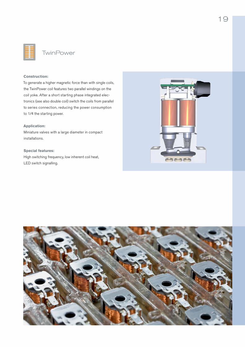
Type 6011 6013 6027
Process connections
Diameter [DN in mm] 1.2 … 2.4 2.0 … 6.0 1.0 … 12.0
Pressure range [bar] 0 … 21 0 … 25 0 … 250
Temperature [°C] -10 … +100 -40 … +180 -40 … +180
2/2-way plunger valve type 6013
Direct-acting 2-way plunger valve
Function:
The main components of this valve type are a coil, a closing spring, a valve body cover and the
valve body with the seat. Without current the path to the outlet is blocked (normally closed), since
the closing spring, supported by the pressure of the medium, presses the plunger onto the valve
seat. If current flows through the coil, the latter generates a starting force, which pulls the plunger
and the seal against the spring force and draws the medium upward. The channel is opened for the
medium.
Application:
This cost-effective valve type is used in universal applications for neutral and clean liquids, gases
and vapours. Versions with special high-quality materials also allow their use in mildly acidic
and alkaline solutions. The direct-acting 2-way plunger valves therefore can be used for diverse
applications, such as shut-off, dosing, filling and ventilation.
Special features:
Due to a spring-damped seat seal, these valve types have a long service life. Especially noteworthy
are the increased switching cycles and service life due to sliding ring bearings. These products are
also suitable for high pressure and temperature ranges.

23
2/2-way plunger valve type 6013
Solenoid coil
Valve body
Valve seat
Electrical connection
De-energised Energised

24 Bürkert | Solenoid Valves
3/2-way plunger valve type 6014
Direct-acting 3-way plunger valve
Function:
The functioning principle of the direct-acting 3-way plunger valve depends on how the fittings
are connected to the fluid system. As opposed to the 2-way plunger valve it has two valve seats
and one return flow. If no electric voltage is present, a normally closed 3/2-way valve allows no
passage from the pressure connection P to connection A (outlet), since a conical spring presses
the plunger onto valve seat 1. At the same time A is directly connected to R (return flow) and valve
seat 2 is opened. If the coil is energised the plunger is pulled in and seals valve seat 2. The path
between A and R is therefore blocked. At the same time valve seat 1 is opened and the channel
between P and A is opened for the medium.
Application:
These valves can be used in diverse applications, such as mixing, distribution, ventilation, dosing,
etc. of neutral gaseous and liquid media. This type is frequently used as a pilot valve for larger
pneumatically actuated valves.
Special features:
Special features of this valve type are the convenient, service-friendly manual override, the energy-
saving pulse design and its suitability for use in explosive areas. In addition there are versions that
are suitable for high-temperature media (hot water, hot air and steam).
Type 6012 6014 0355
Process connections
Diameter [DN in mm] 1.2 … 1.6 1.5 … 2.5 2.0 … 4.0
Pressure range [bar] 0 … 10 0 … 16 0 … 16
Temperature [°C] -10 … +100 -10 … +100 (Polyamid coil)-10 … +120 (Epoxy coil)
-10 … +180

25
3/2-way plunger valve type 6014
Solenoid coil
Valve body
Valve seats
Electrical connection
De-energised Energised
R
PA

26 Bürkert | Solenoid Valves
2/2-way toggle valve type 131
Direct-acting toggle valve
Function:
The valve operates according to the lever principle and can therefore also directly switch large
diameters. It is available both as a 2/2-way and a 3/2-way valve.
The armature acts horizontally on a fixed coupled toggle arm. The sealing cylinder located on the
lower lever is pressed by the horizontal motion onto the valve seats. The plastic encased metal
lever comprises one unit with the gas-tight lead-through. Due to this design the actuator is media
separated from the fluid body.
Application:
Media separation makes this valve especially suitable for use in critical acidic and alkaline solu-
tions or in media that contain particles. Due to the large diameters it is often used as an emptying
and mixing valve.
Special features:
The energy-saving version with power reduction uses the double coil technology with integrated
cast electronics. They are certified worldwide as AC, DC and UC versions and fulfil the voltage
requirements for European rail transport.
These valves are equipped with a locking service-friendly manual override and offer the capability
of potential-free electrical feedback of the switching position.
Type 0131 0131 0131
Process connections
Diameter [DN in mm] 10 … 20 10 … 20 10 … 20
Pressure range [bar] 0 … 3 0 … 3 0 … 1
Temperature [°C] -10 … +130 -10 … +130 -10 … 80

27
2/2-way toggle valve type 131
De-energised Energised
Manual override
Valve body
Toggle
Valve seats
Electronics
Coil
Isolating diaphragm

Pivoted armature valve type 330
28 Bürkert | Solenoid Valves
Direct-acting pivoted armature valve
Function:
This type of valve uses a pivoted armature, a flexible separating diaphragm, two valve seats and
one coil. They can be used both as 3/2-way and 2/2-way versions. Under voltage the pivoted
armature is pulled against the force of the spring and the path between P and A (outlet) is opened.
At the same time the channel between P and B is closed. Without current the pivoted armature
closes valve seat 1 and the medium can flow between connection P and B.
Application:
The use of a separating diaphragm, which separates the media chamber from the magnetic
system, makes it possible to use these valves for the control of corrosive, contaminated and
aggressive fluids as well as for vacuum. These valves are equipped with a lockable manual override
and offer the unique capability of electrical feedback of the switching position, which results in in-
creased safety.
Special features:
Versions for use in explosive areas are available, as well as different materials for media-contacting
components. Decades of engineering experience make it a highly reliable, low-maintenance valve.
Type 0330 0330 0121
Process connections
Diameter [DN in mm] 3.0 … 5.0 2.0 … 4.0 2.0 … 8.0
Pressure range [bar] 0 … 10 0 …16 0 …4
Temperature [°C] -30 … +80 -30 … +90 -30 … +90

29
Pivoted armature valve type 330
Solenoid
Manual override
Valve body
Return spring
Isolating diaphragm
BP
A
Valve seat 2
Pivot
Valve seat 1
Core, pivoted armature
Electrical connection
Distribution valve
De-energised
Distribution valve
Energised
Isolating diaphragm
Optional feedback
Ports in one plane

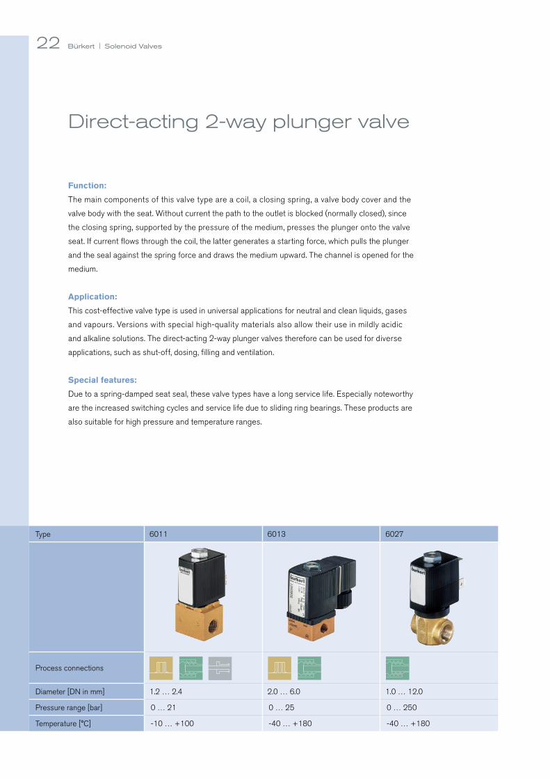
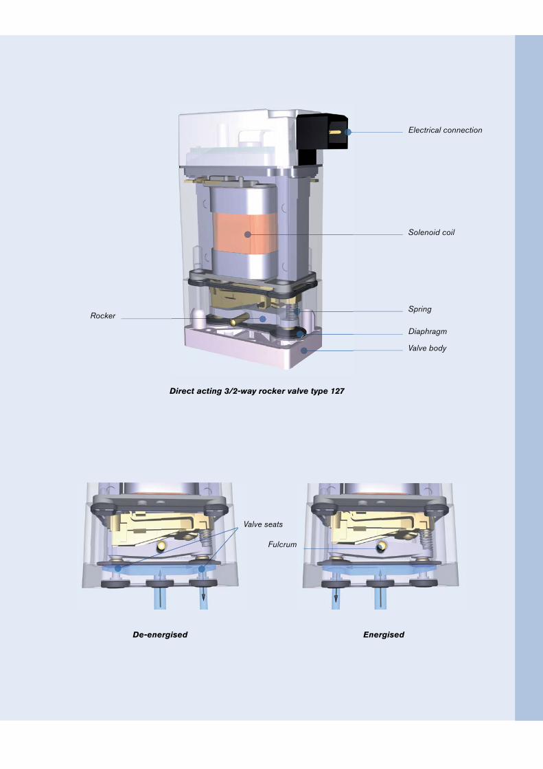
Direct acting 3/2-way rocker valve type 127
30 Bürkert | Solenoid Valves
Direct-acting pivoted rocker valve
Function:
The special feature of direct-acting rocker valves is that all orifices are located on one plane in
the valve body. This functioning principle is suitable both for 2/2-way and for 3/2-way valves.
The valve consists essentially of four main elements: magnetic coil, spring, rocker and two valve
seats. In a 2/2-way valve a spring presses one side of the rocker against one of the two valve seats,
which is sealed in this way. As soon as the coil is energised, supported by an additional spring
it pulls the part of the rocker that was previously pressed against the valve seat. This creates a
“rocking motion” and the valve seat opens. At the same time the other side of the rocker is pressed
against the blind seat. Since it is not completely closed, medium can now flow unhindered through
the valve.
Application:
In the standard version such valves are used for the control of neutral gases and fluids. They can
be used either as single systems or as pilots for pneumatic valves in normal or explosive envi-
ronments. Rocker valves can also be equipped with a separating diaphragm to separate the valve
mechanism from the medium. This makes them suitable also for switching aggressive and high
purity media.
Special features:
The design with an integrated membrane is the basis of the MicroFluidics series, in which minimal
internal volumes and excellent flushability are especially important.
Type 6106 6106 Ex 0127
Process connections
Diameter [DN in mm] 3.0 … 5.0 2.0 … 4.0 2.0 … 8.0
Pressure range [bar] 0 … 10 0 …16 0 …4
Temperature [°C] -30 … +80 -30 … +90 -30 … +90
31
Direct acting 3/2-way rocker valve type 127
Solenoid coil
Valve body
Diaphragm
SpringRocker
Fulcrum
Electrical connection
De-energised Energised
Valve seats

32 Bürkert | Solenoid Valves
Direct-acting TwinPower rocker valve
Function:
TwinPower valves are based on the time-tested rocker technology. The special feature of these
valves is the coil: It is not a conventional coil with a single winding, but rather two coils that are
arranged parallel to each other so that they have more force for switching. The rocker is moved by
a plunger and is stabilised by two springs. The valves are available in 2/2-way and 3/2-way versions.
The plunger is pulled by the innovative TwinPower coil technology, which triggers the movement
of the rocker. In the 2/2-way version this causes the channel to open and the medium can flow
through the valve. The 3/2-way version enables switching between two channels.
Application:
The valves are used for the control of gases and fluids in analytical applications. They are ideal for
switching aggressive and high purity media, since the separating diaphragm ensures a hermetically
sealed coil and only high-quality plastics are used as the sealing and body material.
Special features:
The valves, relative to their size, offer excellent flow rates and outstanding sealing properties
when used with gaseous media.
Type 6624 6626 6628
Process connections
Diameter [DN in mm] 0.8 … 1.6 2.0 … 3.0 2.0 … 3.0
Pressure range [bar] Vac … 5 Vac … 3 Vac … 5
Temperature [°C] -5 … +50 -5 … +50 -5 … +50

33
Direct-acting 3/2-way rocker valve type 6624
De-energised Energised
TwinPower coil
Fluid chamber
Rocker
Electrical connection
Electronics

34
Direct acting 3/2-way flipper valve type 6144
Bürkert | Solenoid Valves
Direct-acting flipper valve
Function:
The functioning principle of this valve type is characterised by a movable flipper element: A flipper
valve uses a technologically advanced, fully encapsulated flexible seal system between two oppos-
ing seats. Minimal friction causes the flipper to move one bearing point beneath the valve seats. The
movement of the permanent magnet causes the switch element to seal one of the two opposing
valve seats and connects the other seat with the working connection.
Application:
These valves are ideal for applications requiring maximum fluidic capacities in extremely com-
pact installations. They are frequently used for repeatable control of neutral gases and liquids.
Flipper valves are also used as pilot valves for pneumatic applications both in normal and ex-
plosive environments.
Special features:
Media separation by means of a diaphragm and the low heat accumulation of the high-performance
coil make it possible to use this type for aggressive and high-purity media. Flipper valves feature
short switching times, low switching noises and minimal wear.
Type 6144 6144 Ex 6650
Process connections
Diameter [DN in mm] 0.6 0.6 0.4 … 0.8
Pressure range [bar] 0 … 10 0 … 7 Vac … 7
Temperature [°C] 0 … +55 0 … +55 +15 … +50

35
Direct acting 3/2-way fl ipper valve type 6144
Solenoid coil
Flipper
Permanent magnet
Isolated chamber
Electrical connection
De-energised Energised
Valve seats

36 Bürkert | Solenoid Valves
Pilot Valve
All of the functional principles explained for direct-acting
valves (plunger, pivoted armature, rocker and flipper valves)
can be used for pilot valves.
Chamber (above diaphragm)
Pressure is equalized in the chamber and is the space into
which the diaphragm or piston recedes to allow flow.
Pilot channels
Allow fluid to move out of the chamber and from the pilot
to downstream to enable the fluid to assist in opening the
main seal.
Equalization hole/channel
Ensures that the inlet pressure and the pressure in the
chamber above the diaphragm or piston are slowly equalised
in order to close the valve.
Above the seat flow
In all pilot-controlled valves the flow takes place above
the valve seat.
Spring
The spring in the chamber supports the media pressure
during closing of the valve. In valves that are exposed to
aggressive chemical fluids the spring is avoided. The media
pressure alone then closes the valve.
Main Orifice
The area on which the media pressure will act and the
gap through which the media will flow when the valve is
energized. Along with the contours of the valve it governs
the pressure drop and the flow rate of the valve.
Process connections
Many fluidic sizes and connections are available to meet
local geographic or industry specific standards.
Seal
A soft material, either a diaphragm or a flat seal attached
to the underside of a solid piston or a plunger which halts
the flow of fluid from one side of the main orifice to the other.
Seat
A raised area at the diameter that concentrates the pres-
sure of the seal. Press-fit seats made of VA are used in
case of potential abrasion or cavitation.
Servo-assisted Valve Anatomy

37
Seat
Main orifi ce
SpringChamber
Equalization
hole / channel
Opening large orifi ces using the direct acting method would require enormous and expensive coils. Therefore servo as-
sisted valves use the power of the fl uid to open the fl ow channel by controlling a small pilot channel to alter the forces
on a larger main seal.
Pilot valve
Pilot channels
Manual override
Main seal
Process connection
Direction of fl ow

38 Bürkert | Solenoid Valves
Servo-assisted: Diaphragm valve with plunger pilot control
Function:
This functioning principle uses a direct-acting plunger valve as the pilot valve and a flexible
diaphragm as the seal for the main seat. As soon as the pilot valve opens, the fluid chamber above
the diaphragm is emptied. The media pressure within the diaphragm raises the diaphragm and
opens the valve so that the medium can flow. If the pilot valve is closed, the media pressure above
the diaphragm builds up again through the small compensation opening and the closing process
is supported additionally by the compression spring. A minimal differential pressure between the
inlet and outlet is necessary for complete opening and closing.
Application:
The main areas of application for this pilot-controlled solenoid diaphragm valve are clean liquid or
gaseous media such as compressed air, water, hydraulic oils, etc. The small pilot valve makes them
less expensive than direct-acting valves for use with higher pressures and larger diameters.
Special features:
Since pilot-controlled valves (also: servo-assisted valves) have only a small pressure equalisation
hole in the diaphragm, they are susceptible to dirt particles and crystallising media, which can clog
the hole. Bürkert valves are designed as soft stop valves. Ex or low power versions are virtually
unproblematic compared with direct-acting valves, since the pilot control valve only has lower
power consumption.
Type 6281 EV 6281 EV
Process connections
Diameter [DN in mm] 13 … 50 13 … 40
Pressure range [bar] 0.2 … 16 0.2 … 16
Temperature [°C] -30 … +120 -30 … +120

39
Servo-assisted diaphragm valve type 6281 EV
Solenoid coil
Pilot valve
Diaphragm
Main valve seat
Pilot valve seat
Main valve
Compression spring
Electrical connection
De-energised Energised

40 Bürkert | Solenoid Valves
Servo-assisted: Coupled diaphragm solenoid valve with plunger pilot control
Function:
This functioning principle uses a direct-acting plunger valve as the pilot valve and a flexible diaphragm
as the main seal. As soon as the pilot valve opens, the fluid chamber above the diaphragm is emptied.
The media pressure within the diaphragm raises the diaphragm and opens the valve so that the
medium can flow. If the pilot valve is closed, the media pressure above the diaphragm builds up
again through the small compensation opening and the closing process is supported additionally
by the compression spring. This valve type can switch without differential pressure, since the
diaphragm holder of the main valve is connected to the armature rigidly or by means of a spring.
The pilot valve alone is capable of partially opening the main valve.
Application:
The main areas of application for pilot-controlled diaphragm solenoid valves are liquid or gaseous
media such as compressed air, water and hydraulic oils in closed circuits in which little or no dif-
ferential pressure is present for opening and closing.
Special features:
Type 290 features a soft-kick function for a longer service life. All of the DC versions feature
energy-saving power reduction. Type 6213 EV uses a spring as a coupling for “diaphragm-friendly”
opening of the main seat in frequent working cycles.
Type 0290 6213 EV 6213 HP00
Process connections
Diameter [DN in mm] 12 … 50 10 … 40 13 … 20
Pressure range [bar] 0 … 16 0 … 10 0 … 10
Temperature [°C] -30 … +120 -30 … + 90 (Polyamid coil)-30 … + 120 (Epoxy coil)
0 … +120 (Epoxy coil)
2/2-way spring coupled servo-assisted solenoid valve type 6213 EV

41
2/2-way spring coupled servo-assisted solenoid valve type 6213 EV
Solenoid coil
Main valve
Pilot valve
Electrical connection
De-energised Energised
Compression spring Diaphragm
Main valve seat
Coupling spring

42 Bürkert | Solenoid Valves
Servo-assisted: Piston valve with plunger pilot control
Function:
This operating method uses a direct acting plunger valve as the pilot valve and the main valve seal
located on the base of a solid piston which moves vertically through a cylindrical chamber. The
fluid chamber above the piston is relieved when the pilot opens. The medium pressure beneath the
piston lifts the piston and opens the valve allowing flow. When the pilot valve is closed, the medium
pressure is allowed to build up again above the piston through the equalizing orifice in the piston
body and closing is aided by the force of the compression spring.
These valves require a minimum pressure differential to exist between the inlet port and the outlet
port and are limited to controlling the same clean media as the non-isolated plunger pilot.
Application:
The main area of application for this servo-assisted solenoid piston valve is the reliable control of
compressed air, neutral gases and steam up to 180 °C with a high number of strokes in diameters
from DN 10 to 65 mm. Piston valves are especially robust for switching of compressible media
such as gas and steam.
2/2-way servo-assisted piston valve type 0406
Type 0406 0404 5404
Process connections
Diameter [DN in mm] 12 … 40 12 … 50 12 … 25
Pressure range [bar] 1 … 12 1 … 12 1 … 50
Temperature [°C] -10 … +180 -10 … +90 -10 … +90

43
2/2-way servo-assisted piston valve type 0406
Solenoid coil
Main valve
Pilot valve
De-energised Energised
Piston Main valve seat

44 Bürkert | Solenoid Valves
Servo-assisted: Fixed coupled piston valve with plunger pilot control
Function:
This functioning principle uses a direct-acting plunger valve as the pilot valve and a fixed coupled
piston as the main seal. In closed state the piston seals the main valve seat. If the valve is energised,
the pilot valve opens the pilot seat. The media pressure and the armature of the pilot valve cause
the piston to move upward and release the main valve seat. If the pilot valve is switched off, this
design provides for slow, impact-free closing of the valve. As opposed to the other pilot-controlled
valve models, these valve types switch also without differential pressure, since the pilot valve alone
opens the main valve seat.
Application:
Fixed coupled valves are used in applications with little or no differential pressure, since the force
of the pilot control valve alone is also sufficient to open the main seat. Neutral gases and steam
are among the primary applications.
Special features:
Special features of the 407 series are a longer service life due to sliding ring bearings and inte-
grated power reduction. Steam versions have a press-fit stainless steel seat. Type 6240 features
a very compact design, stainless steel body and a plastic piston. In addition, the latter valve is also
available in an explosion-protected version.
Type 0407 6240
Process connections
Diameter [DN in mm] 13 … 50 6 and 12
Pressure range [bar] 0 … 10 0 … 40
Temperature [°C] -20 … +180 -40 … +180

45
Servo-assisted piston valve, fi xed coupled, type 407
De-energised Energised
Solenoid coil
Main valve
Fix coupling
Piston

46
Type 5282 0142 0340
Process connections
Diameter [DN in mm] 13 … 65 15 … 50 8 … 40
Pressure range [bar] 0.2 … 10 0.5 … 6 0.5 … 16
Temperature [°C] -30 … +90 0 … +70 0 … +90
Bürkert | Solenoid Valves
Servo-assisted: Diaphragm / piston valve with pivoted armature pilot control
Function:
This unique functioning principle uses a media separated, direct-acting 3/2-way valve as the pi-
lot valve, while the seal of the main valve is a larger flexible diaphragm or a piston. As soon as
the pilot valve opens, the chamber above the piston opens so that the media pressure raises the
diaphragm, therefore allowing the media to flow. If the pilot valve is closed, the channel to the
outlet side is also closed and the media pressure can build up again through the inlet-side pilot
channel. The closing process is additionally supported by the compression spring. A minimal dif-
ferential pressure between the inlet and outlet is needed for complete opening and closing.
Application:
The main area of application for this unusual valve is the reliable switching of mildly contaminated
and aggressive gases and fluids for diameters DN 10 to 65 mm. This type is designed for univer-
sal use. With this valve type there is very little danger of clogging, since the actuator and media
chamber are separated by a diaphragm.
Special features:
In some versions of this valve type the opening and closing speed can be adapted to the applica-
tion and configured for continuous adjustment.

47
Servo-assisted solenoid valve with 3/2-way pilot type 5282
Manual override
Main valve
Speed control
Solenoid coil
Isolating diaphragm
Upstream equalization channel
Electrical connection
De-energised Energised
Compression spring
Diaphragm
Main valve seat
Downstream equalization channel

48 Bürkert | Solenoid Valves
Materials of ConstructionBürkert boasts the most modern fully equipped material test facility in which you will find qualified people who have years
of experience all directed towards you receiving the correct solenoid valves for your application. These tables are an
excerpt from our chemical resistance booklet which is available on the web or from your local Bürkert contact person.
Code Materials of Construction
General chemical resistance
PA Polyamide Resistant to greases, oils, waxes, fuels, weak bases, aliphatic and aromatic hydrocarbons.
EP Epoxy Resistant to nearly all chemicals. Not resistant to low-molecular organic acids in high concentrationsand highly oxidising substances.
1.43051.44011.4581
Stainless steel Resistant to light acids and caustic solutions.
PVC PVC-HT
Polyvinyl chloride, hard
Resistant to most acids and caustic solutions, and saline solutions.
PP PE
Polypropylene Polyethylene
Resistant to many organic solvents, aqueous solutions of acids, bases and salts.
PTFE Polytetrafluore-thylene
Resistant to nearly all chemicals. Not resistant to liquid sodium and fluorides.
PVDF Polyvinylidene fluoride
Not resistant to hot solvents such as ketone, ester and highly alkaline solutions.
Code Materials of Construction
General chemical resistance
PPS Polyphenyl sulfide
Resistant to aqueous mineral acids, bases, aliphatic and aromatic hydrocarbons,many ketones, alcohols, halogenated hydrocarbons, oils, greases, water and hydrolysis.
PEEK Polyetherether-ketone
Resistant to most chemicals.Not resistant to concentrated sulphuric and nitric acid and certain halogenatedhydrocarbons.
PTFE* Polytetrafluore-thylene
Resistant to nearly all chemicals. Not resistant to liquid sodium and fluorides.
EPDM Ethylene propy-len diene rubber
Resistant to ozone and hot water. Not oil and grease resistant.
FKM Fluorocarbon rubber
Resistant to oil and many chemicals, as well as heat.
NBR Nitrite rubber Resistant to oil.
FFKM Perfluorinated elastomers
Resistant to extreme heat, weather and most chemicals.
* only seal material


50
Cat
egor
y
Type
Func
tion
Req
uire
d ∆p
[in
bar
]
Pro
cess
con
nect
ion
Pre
ssur
e ra
nge
[in
bar
] [in
MP
a]
Med
ia t
empe
ratu
re
[in °
C]
Dia
met
er
[DN
in m
m]
Body material Seal material Diaphragm material Media
Spe
cial
fea
ture
s
and
vers
ions
Are
a of
app
licat
ion
Bra
ss
VA
Pla
stic
NB
R
EP
DM
FKM
PTF
E*
FFK
M*
Neu
tral
flui
ds
Con
tam
inat
ed
fluid
s
Agg
ress
ive
fluid
s
Neu
tral
gas
es
Direct-acting plunger valves
6011 2/2 -M5, G1/8,
NPT 1/8, SFB0 … 21 0 … 2.1
-10 … +100 1.2 … 2.4 S S S S S S N N x - - x
6012 3/2 -M5, G1/8 … 1/4,
PIC, NPT 1/8, SFB0 … 10 0 … 1
-10 … +100 1.2 … 2.0 S S S S S S N N x - - x
6013 2/2 -G 1/8 … 3/8,
NPT 1/8 … 3/8, SFB0 … 25 0 … 2.5
-10 … +180 2 … 6 S S N S A S S A x - - x FFKM only as seat seal
6014 3/2 -G 1/8 … 1/4,
NPT 1/8 … 1/4, SFB0 … 16 0 … 1.6
-10 … +120 1.5 … 3.0 S S S S A S A A x - - xPTFE only up to DN 2.0; FFKM
only seat seal and DN 2.0
6027 2/2 -G 1/4 … 1/2,
NPT 1/4 … 1/20 … 30 (100)
0 … 3 (10)-40 … +180 2 … 12 S S N N A S S N x - o x
2610 2/2 -G 1/4 … 1/2,
NPT 1/4 … 1/20 … 10 0 … 1
-200 … +180 6 … 10 S S N N N N S N x - x x Media separated
Direct-acting pivoted armature
valves
03302/2 3/2
- G 1/4, NPT 1/80 … 16 0 … 1.6
-30 … +90 2 … 4 S S N S A S N A x x x x Media separated
03312/2 3/2
- SFB0 … 16 0 … 1.6
-30 … +90 2 … 3 S S N N A S N N x x x x Media separated
01212/2 3/2
- G 1/4, G 3/80 … 4
0 … 0.4-10 … +90 2 … 8 N S S N A S N S x x x x
Up to DN 8, media separated
Direct-acting toggle valves
01312/2 3/2
- G 3/8 … 1/20 … 3
0 … 0.3-30 … +50 10 … 20 S N S N S S N N x x x Media separated
Servo-assisted piston valves
6240 2/2 - G 1/4 … 1/20 … 16 (25/40) 0 … 1.6 (2.5/4)
-40 … +180 6, 12 S S N N A S S N x - o x
5404 2/2 1.0 G 1/2 … 11 … 50 0.1 … 5
-10 … +90 12 … 25 S N N S N A S N x - - x
0404 2/2 1.0G 1/2 … 2 1/2,
NPT 1/4 … 2, DIN flange0 … 3
0 … 0.3-10 … +90 12 … 50 S N N N N N S N x - - x
Flange version in grey cast iron
0406 2/2 1.0G 1/2 … 1, DIN flange
1 … 12 0.1 … 1.2
-10 … +180 13 … 25 S N N N N N S N x - - xFlange version
in grey cast iron
0407 2/2 -G 1/2 … 2, DIN flange
0 … 10 0 … 1
-20 … +180 13 … 50 S N N N N N S N x - - xFlange version in grey cast iron, fixed coupled
0340 3/2 0.5 G 1/4 … 1 1/20.5 … 16
0.05 … 1.60 … +90 8 … 40 S N N S N N N N x - - x Pilot media separated
Servo-assisted diaphragm valves
6213EV 2/2 -
(HP00)G 1/4 … 2,
NPT 3/8 … 10 … 10 0 … 1
-30 … +120 10 … 40 S S N S S S N N x - - x Spring coupled
6281EV 2/2 0.5G 3/8 … 2,
NPT 1/2 … 10.2 … 16
0.02 … 1.6-30 … +120 13 … 50 S S N S S S N N x - - x
0290 2/2 -G 1/2 … 2, NPT 1/2 … 2
1/2, DIN flange0 … 16 0 … 1.6
-30 … +120 12 … 50 S S N S S S N N x - - xFlange version in grey cast iron, fixed coupled
5282 2/2 0.2G 1/2 … 2 1/2,
DIN flange0.2 … 16
0.02 … 1.6-30 … +90 13 … 50 S S S1 S S S N N x x x x
Flange version in grey cast iron, fixed coupled
Solenoid valves at a glance
Bürkert | Solenoid Valves
PIC = Push-in connection | SFB= Specific flange Bürkert

51
Cat
egor
y
Type
Func
tion
Req
uire
d ∆p
[in
bar
]
Pro
cess
con
nect
ion
Pre
ssur
e ra
nge
[in
bar
] [in
MP
a]
Med
ia t
empe
ratu
re
[in °
C]
Dia
met
er
[DN
in m
m]
Body material Seal material Diaphragm material Media
Spe
cial
fea
ture
s
and
vers
ions
Are
a of
app
licat
ion
Bra
ss
VA
Pla
stic
NB
R
EP
DM
FKM
PTF
E*
FFK
M*
Neu
tral
flui
ds
Con
tam
inat
ed
fluid
s
Agg
ress
ive
fluid
s
Neu
tral
gas
es
Direct-acting plunger valves
6011 2/2 -M5, G1/8,
NPT 1/8, SFB0 … 21 0 … 2.1
-10 … +100 1.2 … 2.4 S S S S S S N N x - - x
6012 3/2 -M5, G1/8 … 1/4,
PIC, NPT 1/8, SFB0 … 10 0 … 1
-10 … +100 1.2 … 2.0 S S S S S S N N x - - x
6013 2/2 -G 1/8 … 3/8,
NPT 1/8 … 3/8, SFB0 … 25 0 … 2.5
-10 … +180 2 … 6 S S N S A S S A x - - x FFKM only as seat seal
6014 3/2 -G 1/8 … 1/4,
NPT 1/8 … 1/4, SFB0 … 16 0 … 1.6
-10 … +120 1.5 … 3.0 S S S S A S A A x - - xPTFE only up to DN 2.0; FFKM
only seat seal and DN 2.0
6027 2/2 -G 1/4 … 1/2,
NPT 1/4 … 1/20 … 30 (100)
0 … 3 (10)-40 … +180 2 … 12 S S N N A S S N x - o x
2610 2/2 -G 1/4 … 1/2,
NPT 1/4 … 1/20 … 10 0 … 1
-200 … +180 6 … 10 S S N N N N S N x - x x Media separated
Direct-acting pivoted armature
valves
03302/2 3/2
- G 1/4, NPT 1/80 … 16 0 … 1.6
-30 … +90 2 … 4 S S N S A S N A x x x x Media separated
03312/2 3/2
- SFB0 … 16 0 … 1.6
-30 … +90 2 … 3 S S N N A S N N x x x x Media separated
01212/2 3/2
- G 1/4, G 3/80 … 4
0 … 0.4-10 … +90 2 … 8 N S S N A S N S x x x x
Up to DN 8, media separated
Direct-acting toggle valves
01312/2 3/2
- G 3/8 … 1/20 … 3
0 … 0.3-30 … +50 10 … 20 S N S N S S N N x x x Media separated
Servo-assisted piston valves
6240 2/2 - G 1/4 … 1/20 … 16 (25/40) 0 … 1.6 (2.5/4)
-40 … +180 6, 12 S S N N A S S N x - o x
5404 2/2 1.0 G 1/2 … 11 … 50 0.1 … 5
-10 … +90 12 … 25 S N N S N A S N x - - x
0404 2/2 1.0G 1/2 … 2 1/2,
NPT 1/4 … 2, DIN flange0 … 3
0 … 0.3-10 … +90 12 … 50 S N N N N N S N x - - x
Flange version in grey cast iron
0406 2/2 1.0G 1/2 … 1, DIN flange
1 … 12 0.1 … 1.2
-10 … +180 13 … 25 S N N N N N S N x - - xFlange version
in grey cast iron
0407 2/2 -G 1/2 … 2, DIN flange
0 … 10 0 … 1
-20 … +180 13 … 50 S N N N N N S N x - - xFlange version in grey cast iron, fixed coupled
0340 3/2 0.5 G 1/4 … 1 1/20.5 … 16
0.05 … 1.60 … +90 8 … 40 S N N S N N N N x - - x Pilot media separated
Servo-assisted diaphragm valves
6213EV 2/2 -
(HP00)G 1/4 … 2,
NPT 3/8 … 10 … 10 0 … 1
-30 … +120 10 … 40 S S N S S S N N x - - x Spring coupled
6281EV 2/2 0.5G 3/8 … 2,
NPT 1/2 … 10.2 … 16
0.02 … 1.6-30 … +120 13 … 50 S S N S S S N N x - - x
0290 2/2 -G 1/2 … 2, NPT 1/2 … 2
1/2, DIN flange0 … 16 0 … 1.6
-30 … +120 12 … 50 S S N S S S N N x - - xFlange version in grey cast iron, fixed coupled
5282 2/2 0.2G 1/2 … 2 1/2,
DIN flange0.2 … 16
0.02 … 1.6-30 … +90 13 … 50 S S S1 S S S N N x x x x
Flange version in grey cast iron, fixed coupled
S = Standard | A = On request | N = Not available1 = plastic version: Type 0142
* only as seal material | x = suitable | o = partially suitable | - = not suitable = Gas and /or steam applications | = suitable for water applications
Universal for gases + fluids

52 Bürkert | Solenoid Valves
Cat
egor
y
Type
Func
tion
Req
uire
d ∆p
[in
bar
]
Pro
cess
con
nect
ion
Pre
ssur
e ra
nge
[in
bar
] [in
MP
a]
Med
ia t
empe
ratu
re
[in °
C]
Dia
met
er
[DN
in m
m]
Body material Seal material Diaphragm material Media
Bra
ss
VA
Pla
stic
NB
R
EP
DM
FKM
PTF
E*
FFK
M*
Neu
tral
flui
ds
Con
tam
inat
ed
fluid
s
Agg
ress
ive
fluid
s
Neu
tral
gas
es
Direct-acting rocker valves
0127 3/2 –G 1/8, NPT 1/8,UNF 1/4” - 28
flange
0 … 20 … 0.2
0 … +60 1.5… 1.6 N N S N N S N S N S S N
6104 3/2 – SFB0 … 7
0 … 0.7-10 … +55 0.6 N N S S N S N N N N N S
6106 3/2 – SFB0 … 100 … 1
-10 … +55 0.9 and 1.2 N N S S N S N N N N N S
6126 3/2 – SFB0 … 6
0 … 0.6-10 … +50 0.8 N N S N S S N N S S S N
6128 3/2 – G1/8, SFB0 … 100 … 1
-10 … +70 2.0 and 3.0 N N S S N S N N S S S S
Direct-acting flipper
valves
6124 3/2 – SFB, Hose fitting0 … 3
0 … 0.30 … +55 0.6 N N S N N S N N S S S N
6144 3/2 – SFB0 … 7
0 … 0.7-10 … +55 0.6 N N S S N S N N N N N S
Selection Chart Micro Fluidics
PIC = Push-in connection | SFB= Specific flange Bürkert

53
Cat
egor
y
Type
Func
tion
Req
uire
d ∆p
[in
bar
]
Pro
cess
con
nect
ion
Pre
ssur
e ra
nge
[in
bar
] [in
MP
a]
Med
ia t
empe
ratu
re
[in °
C]
Dia
met
er
[DN
in m
m]
Body material Seal material Diaphragm material Media
Bra
ss
VA
Pla
stic
NB
R
EP
DM
FKM
PTF
E*
FFK
M*
Neu
tral
flui
ds
Con
tam
inat
ed
fluid
s
Agg
ress
ive
fluid
s
Neu
tral
gas
es
Direct-acting rocker valves
0127 3/2 –G 1/8, NPT 1/8,UNF 1/4” - 28
flange
0 … 20 … 0.2
0 … +60 1.5… 1.6 N N S N N S N S N S S N
6104 3/2 – SFB0 … 7
0 … 0.7-10 … +55 0.6 N N S S N S N N N N N S
6106 3/2 – SFB0 … 100 … 1
-10 … +55 0.9 and 1.2 N N S S N S N N N N N S
6126 3/2 – SFB0 … 6
0 … 0.6-10 … +50 0.8 N N S N S S N N S S S N
6128 3/2 – G1/8, SFB0 … 100 … 1
-10 … +70 2.0 and 3.0 N N S S N S N N S S S S
Direct-acting flipper
valves
6124 3/2 – SFB, Hose fitting0 … 3
0 … 0.30 … +55 0.6 N N S N N S N N S S S N
6144 3/2 – SFB0 … 7
0 … 0.7-10 … +55 0.6 N N S S N S N N N N N S
S = Standard | A = On request | N = Not available * only as seal material | x = suitable | o = partially suitable | - = not suitable

54 Bürkert | Solenoid Valves
Added Value Systems
Connect Conceive & Innovate
01 02
As a globally flexible, lean, focused and
innovative company we are the partner
of choice for fluid control systems in
more than 35 countries. Whether you
are in Stuttgart, Singapore, Chicago or
Sydney, everywhere in the world, we
are close to you and therefore know at
first-hand about your specific tasks
and problems.
Following our principle of “one face to the
customer”, you have a competent, re-
liable consultant by your side at all times,
who listens to your needs and presents
a solution in your daily application lan-
guage … crossing conventional bounda-
ries and creating synergies between
industries in pursuit of your ideal solution.
Systemhaus crews in Charlotte (USA),
Suzhou (China), Dresden, Ingelfingen
and Dortmund are continuously in innova-
tion mode. They creatively engineer cost
effective solutions to meet difficult
process challenges for our customers.
Bürkert has a unique perspective
in the process control and instru-
mentation industry as we are the
only single brand which combines
a complete range of valves, in-
struments, pneumatic actuation,
networking and controllers from
a single source.
With our dedicated world-class
engineers and our superlative
manufacturing facilities we can
deliver systems which meet your
exact requirements.
Your reliable Bürkert sales con-
sultant and our system engineers
work in concert to ask the right
questions and provide the right
hardware. Transparent operations,
up to date situation, review proce-
dure, engineering change notices,
portals through SAP and secure
intranet are normal in our projects.
For a world class system experi-
ence, insist on Bürkert people to
be part of your next project.
Your project team starts working for you:
from your reliable sales consultant,
qualified industry specialists to dedicated
system engineers – Bürkert puts the
necessary experts together.
For the entire duration of the project they
work together, combining their experi-
ence and clarifying all the requirements
in close cooperation with you to come
up with a feasible draft of your solution
within the shortest timeframe.
CAD-created animations or simulations,
combined with extended manufacturing,
materials, tool design, construction and
assembly knowledge enable us to pro-
vide a rough but firm production concept
for your system at an early stage.

55System Solutions
Plan & Specify Do & Check Complete
03 04 05
Good communication, coordination and
documentation at all project phases
make sure that we are on the right track,
developing the right solution, to allow
us to quickly move on to prototyping.
Thanks to the latest technology, we are
able to build a prototype made of metal
or plastic or a functional model to test
flow for example within 24 hours.
We provide you with samples; we per-
form tests and, of course, obtain all the
necessary local and global approvals
to make sure the system can go to pro-
duction.
From here we work in concert with one
of our production facilities in Ingelfin-
gen, Gerabronn, Criesbach, Öhringen or
Triembach according to their individual
core manufacturing competencies.
In Phase 3 the project is planned in detail.
A specification sheet and refined solu-
tion concept are developed. This defines
exactly what you expect from the system
and what it must provide to ensure that
all components meet your requirements.
At the end of this phase you are present-
ed with a detailed product definition, a
production specification and precise
commercial conditions and agreements.
Structured project management based
on open communication, effective co-
ordination and thorough documentation
ensures fast and reliable results.
Our work does not end with the perfect
delivery of components and systems. We
offer a comprehensive program to our
global clients interlinking services ranging
from maintenance and service contracts,
operator training and integrated logistics.
Our customer service is available around
the clock, offering support through inter-
net, telephone or our qualified, experi-
enced people at your site.
We aim to provide only the utmost in
customer experience. Something you will
tell your friends about.

56 Bürkert | Solenoid Valves
Systems
The combination of customised fl uidics and the right valve types always offers a compact and cost-optimised
alternative. Here you will fi nd an overview of customised system solutions.
Foam distributor Gas control system
Gas mixer Car wash distributor

57
Vacuum control unit Water mixing unit
Medical insuffl ation control

58 Bürkert | Solenoid Valves
We have made the investment to be close to you both geographically and in your market. We offer
a comprehensive program of interlinking services which include:
Everything from one Partner
We have tens of thousand of process engineering products in our program. We know exactly how
to program them, install them and combine them according to your wishes.
Customer Service around the Clock
We offer support through internet, telephone or people on the ground at your site. We are available
around the clock.
Start-up
We are always available for installation and commissioning as well as for local staff and operator
training.
Global Operations
We are close by in 35 countries in a network which guarantees the full achievement of our enter-
prise to each customer on each continent.
Please be assured that we are always available to help personally, really listening to your require-
ments with your success in mind. We are only content when your specific problem was solved.
Our Service Promise

59
Bürkert – Close to You
China
Hong Kong
India
Japan
Korea
Malaysia
Philippines
Singapore
Taiwan
South Africa
Russia
United
Arab
EmiratesArgentina
Brazil
Canada
USA
Australia
New Zealand
For up-to-date addresses
please visit us at
www.burkert.com.
Austria
Belgium
Czech Republic
Denmark
Finland
France
Germany
Italy
Netherlands
Norway
Poland
Portugal
Spain
Sweden
Switzerland
Turkey
United Kingdom
Credits: © and concept: Christian Bürkert GmbH & Co. KG | Realization: Scanner GmbH | Photography: Münch Lichtbildnerei, Stuttgart; Studio Flamisch, Düsseldorf |
3D-Drawings: 3D Sales Technologies GmbH. All people shown are employees at Bürkert. Thank you for your support (and spirit).

Bürkert Fluid Control SystemsChristian-Bürkert-Straße 13-1774653 IngelfingenGermany
Tel. +49 (0) 7940/10-0Fax +49 (0) 7940/10-91 204
89
44
86
/ V
ersi
on 0
3/2
01
4 P
rint 0
3/2
01
4