Product Manual for Dionex IonPac CS19 Column - Cromlab · Product Manual for Thermo Scientific...
59
Thermo Scientific Dionex IonPac CS19 Columns Product Manual P/N: 065440-02 June 2012 Part of Thermo Fisher Scientific
Transcript of Product Manual for Dionex IonPac CS19 Column - Cromlab · Product Manual for Thermo Scientific...

Thermo Scientific
Dionex IonPac CS19 Columns
Product Manual
P/N: 065440-02 June 2012
Part of Thermo Fisher Scientific

Product Manual for Thermo Scientific Dionex IonPac™ CS19 Column Page 1 of 58
Document No. 065440-02 © 2012 Thermo Fisher Scientific June 2012
Product Manual
for
Thermo Scientific Dionex IonPac™ CS19 Analytical Column 2 x 250 mm, P/N 076028 4 x 250 mm, P/N 076026
Thermo Scientific Dionex IonPac™ CS19 Capillary Column
0.4 x 250 mm P/N 076024
Thermo Scientific Dionex IonPac™ CG19 Guard Column 2 x 50 mm, P/N 076029 4 x 50 mm, P/N 076027
Thermo Scientific Dionex IonPac™ CG19 Capillary Guard Column
0.4 x 50 mm, P/N 076025
© 2012 Thermo Fisher Scientific
Document No. 065440 Revision 02 June 2012

Product Manual for Thermo Scientific Dionex IonPac™ CS19 Column Page 2 of 58
Document No. 065440-02 © 2012 Thermo Fisher Scientific June 2012
TABLE OF CONTENTS
SECTION 1 – INTRODUCTION............................................................................................................ 5
SECTION 2 – ION CHROMATOGRAPHY SYSTEMS...................................................................... 7
SECTION 3 – INSTALLATION ............................................................................................................. 8 3.1. System Requirements ............................................................................................................................................... 8
3.1.1. System Requirements for 0.4 mm Operation ..................................................................................................... 8 3.1.2. System Requirements for 2-mm Operation ....................................................................................................... 8 3.1.3. System Requirements for 4-mm Operation ....................................................................................................... 8 3.1.4. System Void Volume......................................................................................................................................... 8
3.2. Installing the Dionex CR-CTC Trap Column for Use with Dionex EGC MSA Cartridge ........................................ 9 3.3. Installing the Dionex CTC-1 Cation Trap Column for Eluent Step Change or Gradient Operation .............................................................................................................................. 9 3.4. The Injection Loop ..................................................................................................................................................... 9
3.4.1. The 0.4-mm System Injection Loop, 0.4 μL Internal Loop ............................................................................... 9 3.4.2. The 2-mm System Injection Loop, 2 - 15 µL .................................................................................................... 9 3.4.3. The 4-mm System Injection Loop, 10 - 50 µL ................................................................................................ 10
3.5. Sample Concentration .............................................................................................................................................. 10 3.6. Dionex IonPac CG19 Guard/Capillary Guard Column ............................................................................................ 11 3.7. Eluent Storage .......................................................................................................................................................... 11 3.8. Dionex Cation Self-Regenerating Suppressor and
Dionex Cation Capillary Electrolytic Suppressor Requirements ............................................................................. 11 3.9. Dionex Cation Atlas Electrolytic Suppressor Requirements .................................................................................... 11 3.10. Dionex Cation MicroMembrane Suppressor Requirements ..................................................................................... 12 3.11. Using Displacement Chemical Regeneration (DCR) with the
Chemical Suppression Mode .................................................................................................................................... 12 3.12. Using Dionex AutoRegen™ with the Chemical Suppression Mode ......................................................................... 12 3.13. Detector Requirements ............................................................................................................................................. 13 3.14. Installation of the Capillary Column ........................................................................................................................ 13
SECTION 4 – OPERATION ................................................................................................................. 17 4.1. General Operating Conditions .................................................................................................................................. 17 4.2. Dionex IonPac CS19 Operation Precautions ............................................................................................................ 17 4.3. Chemical Purity Requirements ................................................................................................................................. 18
4.3.1. Deionized Water .............................................................................................................................................. 18 4.3.2. Inorganic Chemicals ........................................................................................................................................ 18
4.4. Preparation of Eluent Stock Solution Concentrates.................................................................................................. 19 4.4.1. 1.0 N Methanesulfonic Acid (MSA) Stock Solution ....................................................................................... 19 4.4.2. 0.4 N Dionex Methanesulfonic Acid (MSA) Eluent Concentrate ................................................................... 19 4.4.3. 1.0 N Sulfuric Acid Stock Solution ................................................................................................................. 20 4.4.4. Eluent Preparation ........................................................................................................................................... 20
4.5. Making and Using Eluents that Contain Solvents .................................................................................................... 21

Product Manual for Thermo Scientific Dionex IonPac™ CS19 Column Page 3 of 58
Document No. 065440-02 © 2012 Thermo Fisher Scientific June 2012
SECTION 5 – EXAMPLE APPLICATIONS ...................................................................................... 22 5.1. Isocratic Elution of the Common Six Cations using the Dionex IonPac CS19 (2x250 mm),
with/without Dionex IonPac CG19 (2x50 mm) ....................................................................................................... 22 5.2. Isocratic Elution of the Common Six Cations using the Dionex IonPac CS19 (0.4x250 mm),
with/without Dionex IonPac CG19 (0.4x50 mm) .................................................................................................... 23 5.3. Isocratic Elution of Group I & Group II Cations plus Ammonium using the Dionex IonPac CG19 and the
Dionex IonPac CS19 Columns (2x250 mm) ............................................................................................................ 24 5.4. Separation of Six Common Cations plus Ethylamines using the Dionex IonPac CG19 and the
Dionex IonPac CS19 (2x250 mm) ........................................................................................................................... 25 5.5. Gradient Elution of Six Common Cations plus Methylamines using the
Dionex IonPac CS19 (2x250 mm) ........................................................................................................................... 26 5.6. Separation of Six Common Cations plus Methylamines using the
Dionex IonPac CS19 (4x250 mm) ........................................................................................................................... 27 5.7. Isocratic Elution of the Six Common Cations plus Alkanolamines using the
Dionex IonPac CG19/CS19 (2x250 mm) ................................................................................................................. 28 5.8. Separation of Six Common Cations plus Biogenic Amines using the
Dionex IonPac CS19 (4x250 mm) ........................................................................................................................... 29 5.9. Separation of Six Common Cations plus Biogenic Amines using the
Dionex IonPac CG19/CS19 (2x250 mm) ................................................................................................................. 30 5.10. Fast Separation of Six Common Cations plus Biogenic Amines using the
Dionex IonPac CG19/CS19 (2 x 250 mm) ............................................................................................................... 31 5.11. Separation of Six Common Cations plus Biogenic Amines using the
Dionex IonPac CS19 (0.4x250 mm) ........................................................................................................................ 32 5.12. Separation of Six Common Cations, Methylamines and Imidazoles using the
Dionex IonPac CS19 (2x250mm) ............................................................................................................................ 33 5.13. Separation of Six Common Cations plus Paraquat and Diquat using the
Dionex IonPac CS19 (2x250mm) ............................................................................................................................ 34 5.14. Separation of Six Common Cations plus Paraquat and Diquat using the
Dionex IonPac CS19 (4x250mm) ............................................................................................................................ 35 5.15. Fast Separation of Six Common Cations plus Paraquat and Diquat using the
Dionex IonPac CS19 (4x250mm) ............................................................................................................................ 36

Product Manual for Thermo Scientific Dionex IonPac™ CS19 Column Page 4 of 58
Document No. 065440-02 © 2012 Thermo Fisher Scientific June 2012
SECTION 6 – TROUBLESHOOTING GUIDE .................................................................................. 37 6.1. High Back Pressure ................................................................................................................................ 38
6.1.1. Finding the Source of High System Pressure .................................................................................................. 38 6.1.2. Replacing Column Bed Support Assemblies (2 mm and 4 mm columns only) ............................................... 39
6.2. Preparation of Eluents .............................................................................................................................................. 40 6.3. Contamination .......................................................................................................................................................... 40
6.3.1. Suppressor Contamination ............................................................................................................................... 40 6.3.2. A Contaminated Guard or Analytical/Capillary Column ................................................................................ 41 6.3.3. Sample Loop and/or Tubing Contamination ................................................................................................... 42
6.4. High Background or Noise ....................................................................................................................................... 43 6.5. Suppressor Not Suppressing Properly ...................................................................................................................... 44 6.6. Poor Peak Resolution ............................................................................................................................................... 45
6.6.1. Loss of Peak Efficiency Throughout the Chromatogram ................................................................................ 45 6.6.2. Loss of Resolution Throughout the Chromatogram Due to Shortened Retention Times ................................ 46 6.6.3. Loss of Early Eluting Peak Resolution ............................................................................................................ 46
6.7. Spurious Peaks ......................................................................................................................................................... 47 6.8. Poor Efficiency Using Capillary Columns ............................................................................................................... 48
APPENDIX A - QUALITY ASSURANCE REPORT ......................................................................... 49 Quality Assurance Report - Dionex IonPac CS19 Analytical Column - 4 x 250 mm ........................................................... 50 Quality Assurance Report - Dionex IonPac CS19 Analytical Column - 2 x 250 mm ........................................................... 51 Quality Assurance Report - Dionex IonPac CS19 Capillary Column - 0.4 x 250 mm .......................................................... 52
APPENDIX B - COLUMN CARE ........................................................................................................ 53 B.1 Recommended Operating Pressures ......................................................................................................................... 53 B.2 Column Start-Up ...................................................................................................................................................... 53 B.3 Column Storage ........................................................................................................................................................ 53 B.4 Column Cleanup ....................................................................................................................................................... 54
APPENDIX C – CONFIGURATION ................................................................................................... 57 C.1 Configuration of Ion Chromatography (IC) Systems ............................................................................................... 57 C.2 Tubing Back Pressures ............................................................................................................................................. 58

Product Manual for Thermo Scientific Dionex IonPac™ CS19 Column Page 5 of 58
Document No. 065440-02 © 2012 Thermo Fisher Scientific June 2012
SECTION 1 – INTRODUCTION The Thermo Scientific Dionex IonPac CS19 column is used with suppressed conductivity detection for the analyses of the common inorganic cations (Lithium, Sodium, Ammonium, Potassium, Magnesium, and Calcium) as well as small polar amines. Its selectivity is particularly useful in the analysis of small, hydrophilic amines such as ethanolamines, methylamines, ethylamines and the biogenic amines. The Dionex IonPac CS19 stationary phase has a higher cation exchange capacity than the Dionex IonPac CS17 and the Dionex IonPac CS18 columns. Its supermacroporous polymeric substrate is functionalized with carboxylic acid groups. It is compatible with up to 100% organic solvents (such as acetonitrile and acetone). Isopropyl alcohol (IPA) should be avoided as an eluent component because it will cause very high backpressure in the Dionex IonPac CS19 column. IPA, however, can be used to clean the column at very low flow rates or can be present in the sample matrix. The Dionex IonPac CS19 column can be used without loss of performance up to 40 °C. It can be washed with up to 1 M acid concentration. The Dionex IonPac CS19 column should not be used with basic eluents. The column backpressure increases too much, disrupting the packing. The Dionex IonPac CS19 column can be used with up to 1.5 times its standard flow rate. The Dionex IonPac CS19 Capillary Column (0.4 x 250 mm) is packed with the same material as the equivalent standard bore version (producing the same performance as a 4 mm column) but requires less eluent consumption, thus reduced operating costs. The IonPac CG19 guard column is made with microporous polymeric resin. It has the same functionality as the separator resin, but is of much lower capacity and therefore cannot be used to concentrate samples prior to analysis. All of the CG19 guard columns are packed with the same resin. Read the system manuals. This manual assumes that you are familiar with the installation and operation of the Thermo Scientific Dionex Ion Chromatograph (IC). If you do not understand the operation of the system, take the time to familiarize yourself with the various system components before beginning an analysis. All instrument manuals are available on the Dionex Reference Library CD-ROM supplied with this column. You may need to make a liquid line fitting. The Dionex IonPac CS19 Analytical Column and the Dionex IonPac CG19 Guard Column have 10-32 PEEK end fittings for use with ferrule/bolt liquid line fittings. If you have an Ion Chromatograph with Tefzel® liquid lines having 1/4-28 ThermoFlare fittings, it will be necessary to obtain one or more Tefzel liquid lines with a PEEK bolt and ferrule fitting on one end and a 1/4-28 ThermoFlare fitting on the other end.

Product Manual for Thermo Scientific Dionex IonPac™ CS19 Column Page 6 of 58
Document No. 065440-02 © 2012 Thermo Fisher Scientific June 2012
NOTE!
Table 1 Dionex IonPac CS19/CG19 Packing Specifications
Column Particle
Diameter µm
Substrate Column Capacity µeq/column
Functional Group
Hydrophobicity
Dionex IonPac CS19 Capillary Column 0.4 x 250 mm
5.5 SMP 24 Carboxylic acid Medium
Dionex IonPac CG19 Capillary Guard Column 0.4 x 50 mm
8.0 Microporous 0.5 Carboxylic acid Medium
Dionex IonPac CS19 Analytical Column 2 x 250 mm
5.5 SMP 600 Carboxylic acid Medium
Dionex IonPac CG19 Guard Column 2 x 50 mm
8.0 Microporous 11 Carboxylic acid Medium
Dionex IonPac CS19 Analytical Column 4 x 250 mm
5.5 SMP 2410 Carboxylic acid Medium
Dionex IonPac CG19 Guard Column 4 x 50 mm
8.0 Microporous 46 Carboxylic acid Medium
Table 2 Dionex IonPac CS19/CG19 Operating Parameters
Column Typical Back Pressure
at Standard Flow Rate psi (MPa)
Standard Flow Rate mL/min
Maximum Flow Rate mL/min
Dionex IonPac CS19 0.4 mm Capillary Column
< 1,800 (12.41) 0.010 0.015
Dionex IonPac CG19 0.4 mm Capillary Guard Column
< 200 (1.38) 0.010 0.015
Dionex IonPac CS19 + CG19 0.4 mm Columns
< 2,000 (13.79) 0.010 0.015
Dionex IonPac CS19 2-mm Analytical Column
< 1,800 (12.41) 0.25 0.375
Dionex IonPac CG19 2-mm Guard Column < 200 (1.38) 0.25 0.375
Dionex IonPac CS19 + CG19 2-mm Columns < 2,000 (13.79) 0.25 0.375 Dionex IonPac CS19 4 mm Analytical Column
< 1,800 (12.41) 1.0 1.5
Dionex IonPac CG19 4 mm Guard Column < 200 (1.38) 1.0 1.5
Dionex IonPac CS19 + CG19 4 mm Columns < 2,000 (13.79) 1.0 1.5
For assistance, contact Technical Support for Dionex Products. In the U.S., call 1-800-346-6390. Outside the U.S., call the nearest Thermo Fisher Scientific office.

Product Manual for Thermo Scientific Dionex IonPac™ CS19 Column Page 7 of 58
Document No. 065440-02 © 2012 Thermo Fisher Scientific June 2012
SECTION 2 – ION CHROMATOGRAPHY SYSTEMS The proper configuration of an Ion Chromatography System (ICS) in 2-mm or 4-mm format is based on the ratio of the 2-mm to 4-mm column cross-sectional area (a factor of 1/4). The selected format will affect the type of pump recommended. A gradient pump is designed to blend and pump isocratic, linear, or gradient mixtures of up to four mobile phase components at precisely controlled flow rates. An isocratic pump is for applications not requiring gradient and multi-eluent proportioning capabilities. Both are offered in either standard bore or microbore options.
• For an ICS in 2-mm format, a microbore isocratic pump, standard bore isocratic pump, microbore gradient pump, or standard bore gradient pump is recommended.
• For an ICS in 4-mm format, a standard bore isocratic pump or standard bore gradient pump is recommended. • For an ICS in 0.4-mm format, a Capillary IC system such as the Thermo Scientific Dionex ICS-5000 system is
recommended. See Appendix B, "Configuration" for specific recommended settings and parts including pumps, eluent flow rate, Thermo Scientific Dionex Self-Regenerating Suppressor (Dionex SRS), Thermo Scientific Dionex MicroMembrane Suppressor (Dionex MMS), Thermo Scientific Dionex Capillary Electrolytic Suppressor (Dionex CES), Thermo Scientific Dionex Atlas Electrolytic Suppressor (Dionex AES), injection loop, system void volume, detectors, and tubing back pressure.

Product Manual for Thermo Scientific Dionex IonPac™ CS19 Column Page 8 of 58
Document No. 065440-02 © 2012 Thermo Fisher Scientific June 2012
SECTION 3 – INSTALLATION
3.1. System Requirements 3.1.1. System Requirements for 0.4 mm Operation The Dionex IonPac CS19 0.4-mm Capillary Guard and Capillary Columns are designed to be run on a Capillary Ion Chromatograph equipped with Suppressed Conductivity detection. It is recommended to run the Capillary Column only on the Dionex ICS-5000 Capillary System for best performance. Use only precut 0.4-mm tubing with the Dionex ICS-5000 Capillary System.
3.1.2. System Requirements for 2-mm Operation The Dionex IonPac CS19 2-mm Guard Column and Analytical Column are designed to be run on any Dionex ICS Ion Chromatograph equipped with suppressed conductivity detection.
3.1.3. System Requirements for 4-mm Operation The Dionex IonPac CS19 4-mm Guard and Analytical Columns are designed to be run on any Dionex ICS Ion Chromatograph equipped with suppressed conductivity detection. 3.1.4. System Void Volume When using 2-mm columns, it is particularly important to minimize system void volume. The system void volume should be scaled down to at least 1/4 of the system volume in a standard 4-mm system. For best performance, all of the tubing installed between the injection valve and detector should be 0.005" (P/N 044221) ID PEEK tubing, for a 2-mm system. For a 4-mm system, 0.010" ID PEEK tubing (P/N 042260) is recommended; 0.012" Tefzel tubing may be used, but peak efficiency will be compromised, which may also result in decreased peak resolution. Minimize the lengths of all connecting tubing and the tubing must be cut with a straight edge, NOT slanted. Remove all unnecessary switching valves and couplers. Make sure that a 2-mm Gradient Mixer is used (and not a 4-mm Gradient Mixer) when using 2-mm columns. Any void volumes and eddies will result in analyte dispersion, which produces poor peak efficiencies.

Product Manual for Thermo Scientific Dionex IonPac™ CS19 Column Page 9 of 58
Document No. 065440-02 © 2012 Thermo Fisher Scientific June 2012
3.2. Installing the Dionex CR-CTC Trap Column for Use with Dionex EGC MSA Cartridge For Dionex IonPac CS19 applications using the Thermo Scientific Dionex EGC MSA cartridge, a Thermo Scientific Dionex CR-CTC Continuously Regenerated Cation Trap Column (P/N 066262 or 072079) may be installed at the Dionex EGC eluent outlet to remove trace level cationic contaminants such as ammonium from the carrier deionized water. See the Dionex CR-TC Product Manual (Document No. 031910) for instructions. As an alternative, the Dionex CTC-1 Trap Column (P/N 040192) can be used. The Thermo Scientific Dionex CTC-1 Trap Column will require off-line regeneration.
3.3. Installing the Dionex CTC-1 Cation Trap Column for Eluent Step Change or Gradient Operation
For gradient operation, a Dionex Cation Trap Column (Dionex CTC-1, P/N 040192, for 4-mm Dionex IonPac CS19 or Dionex CTC (2-mm), P/N 043132 for 2-mm Dionex IonPac CS19) is installed between the gradient pump and the injection valve. Remove the high pressure gradient mixer if present. The Dionex CTC is filled with high capacity cation exchange resin which helps to minimize the baseline shift caused by increasing cationic contaminant levels in the eluent as the ionic concentration of the eluent is increased over the course of the gradient analysis. To install the Dionex CTC, complete the following steps:
A. Remove the Gradient Mixer. It is installed between the gradient pump pressure transducer and the injection valve. B. Connect the gradient pump directly to the Dionex CTC. Connect a waste line to the Dionex CTC outlet and
direct the line to a waste container. C. Flush the Dionex CTC. Note that with the guard and analytical columns out of line, there is no need for flow
rate restrictions. For the Dionex CTC (2-mm), use 50 mL of a 10x eluent concentrate of the strongest eluent required by the application at a flow rate of 0.5 mL/min. For the Dionex CTC-1 (4-mm) use 200 mL of a 10x eluent concentrate of the strongest eluent required by the application at a flow rate of 2.0 mL/min.
D. Rinse the Dionex CTC. Use the strongest eluent that will be used during the gradient analysis. E. Reconnect the Dionex CTC. Connect the Dionex CTC to the eluent line that is connected to the injection valve
inlet.
The background conductivity of your system should be less than 0.5 µS when 8 mN sulfuric acid (H2SO4) or methanesulfonic acid (MSA) is being pumped through the chromatographic system with the Dionex CSRS in-line and properly functioning. The baseline shift should be no greater than 0.1 µS during a gradient concentration ramp from 3 to 30 mM methanesulfonic acid (MSA). If the baseline shifts are greater than 0.2 µS after equilibration, the Dionex CTC should be cleaned using steps A - E above.
3.4. The Injection Loop 3.4.1. The 0.4-mm System Injection Loop, 0.4 μL Internal Loop For most applications on a 0.4-mm capillary system, a 0.4 µL injection loop is sufficient. Generally, you should not inject more than 0.5 nanomoles total cation concentration onto the 0.4-mm capillary column. Injecting a larger number of moles of a sample can result in overloading the column which can affect the detection linearity. For low concentrations of analytes, larger injection loops can be used to increase sensitivity. 3.4.2. The 2-mm System Injection Loop, 2 - 15 µL For most applications on a 2-mm analytical system, a 2 - 15 µL injection loop is sufficient. Generally, you should not inject more than 12.5 nanomoles of any one analyte onto a 2-mm analytical column. Injecting larger number of moles of a sample can result in overloading the column which can affect the detection linearity. For low concentrations of analytes, larger injection loops can be used to increase sensitivity. The Dionex IonPac CS19 2-mm requires a microbore system configuration. Install an injection loop one-fourth or less (<15 µL) of the loop volume used with a 4-mm analytical system (Section 2, “Comparison of 2-mm and 4-mm Ion Chromatography Systems”).

Product Manual for Thermo Scientific Dionex IonPac™ CS19 Column Page 10 of 58
Document No. 065440-02 © 2012 Thermo Fisher Scientific June 2012
WARNING!
3.4.3. The 4-mm System Injection Loop, 10 - 50 µL For most applications on a 4-mm analytical system, a 10 - 50 µL injection loop is sufficient. Generally, you should not inject more than 50 nanomoles of any one analyte onto the 4-mm analytical column. Injecting larger number of moles of a sample can result in overloading the column which can affect the detection linearity. For low concentrations of analytes, larger injection loops can be used to increase sensitivity.
3.5. Sample Concentration Trace cation concentrators are used primarily in high purity water analysis. The function of the trace cation concentrator in these applications is to strip ions from a measured volume of a relatively clean aqueous sample matrix. This can be accomplished by replacing the sample loop with the concentrator column, then pumping (and concentrating) large volumes of the sample onto a concentrator column. The sample should be pumped into the concentrator column in the OPPOSITE direction of the eluent flow, otherwise the chromatography will be compromised. This process “concentrates” all cationic analyte species onto the Dionex Trace Cation Concentrator (Dionex TCC-LP1, Dionex TCC-ULP1, Dionex TCC-XLP1) leading to a lowering of detection limits by 2-5 orders of magnitude. The unique advantage of the Dionex Trace Cation Concentrator for the analytical chemist in these applications is the capability of performing routine trace analyses of sample matrix ions at ng/L levels without extensive and laborious sample pretreatment.
Another advantage of the Dionex TCC-LP1, Dionex TCC-ULP1, and Dionex TCC-XLP1 is that because of their low backpressure, samples can be preconcentrated using a hand-held syringe.
The Dionex Low-Pressure Trace Cation Concentrator (Dionex TCC-LP1, P/N 046027) should be used for sample concentration with the Dionex IonPac CS19 4-mm or the CS19 2-mm Analytical Columns. For trace cation concentration with the Dionex IonPac CS19 0.4 mm Column, use the Dionex IonSwift MCC-100 Concentrator Column (0.5 x 80 mm, P/N 075462).
The Dionex IonPac CG19 Guard Column should not be used as a concentrator column, as it has very low cation exchange capacity.
For more detailed information on sample concentration techniques for high sensitivity work and a detailed discussion of cation concentration techniques refer to:
• Section 3, “Operation,” of the Thermo Scientific Dionex Trace Cation Concentrator Low Pressure (Dionex TCC-LP1), Dionex Ultra Low Pressure (Dionex TCC-ULP1) and Dionex Extremely Low Pressure (Dionex TCC-XLP1) Column Product Manual (Document No. 034973),
• Section 3, “Operation” of the Thermo Scientific Dionex Monolith Anion Concentrator Column (Dionex IonSwift MCC-100 / Dionex IonSwift MCC-200) Column Manual (Document No. 065411).
The Dionex Trace Cation Concentrator (Dionex TCC-2, P/N 043103) should not be used for sample concentration with the Dionex IonPac CS19 column. The Dionex TCC-2 column packing is a strong cation exchange resin functionalized with sulfonic acid. The recommended Dionex IonPac CS19 eluents will not properly elute ions concentrated on this column.

Product Manual for Thermo Scientific Dionex IonPac™ CS19 Column Page 11 of 58
Document No. 065440-02 © 2012 Thermo Fisher Scientific June 2012
3.6. Dionex IonPac CG19 Guard/Capillary Guard Column A Dionex IonPac CG19 Guard/Capillary Guard Column is normally used with the Dionex IonPac CS19 Analytical/Capillary Column. The Dionex IonPac CG19 has a microporous polymeric substrate and is a very low capacity cation exchange column, adding only about 0.5 minutes to the elution time. It should not be used as a concentrator column. A guard column is placed prior to the analytical/capillary column to prevent sample contaminants from eluting onto the analytical/capillary column. Cleaning or replacing a guard column is more economical than replacing an analytical/capillary column. For maximum life of the analytical/capillary column, the guard column should be changed or replaced as part of a regular maintenance schedule or at the first sign of performance deterioration. Use the test chromatogram that is shipped with the analytical/capillary column or the initial application run as a performance benchmark. 3.7. Eluent Storage Dionex IonPac CS19 columns are designed to be used with acid eluent systems. Storage under a helium atmosphere ensures contamination free operation and proper pump performance (nitrogen can be used if eluents do not contain solvents). The recommended column storage solution is 8mM MSA. Eluent storage bottles made of glass should be avoided as sodium contamination will occur.
3.8. Dionex Cation Self-Regenerating Suppressor and Dionex Cation Capillary Electrolytic Suppressor Requirements
A Dionex Cation Self-Regenerating Suppressor (Dionex CSRS 300, 2-mm or 4-mm respectively) should be used for 2-mm and 4-mm applications that require suppressed conductivity detection. A Dionex Cation Capillary Electrolytic Suppressor (Dionex CCES 300) should be used for the 0.4 mm capillary applications that require suppressed conductivity. They are compatible with solvent containing eluents and aqueous ionic eluents of all concentrations with which the systems and columns are compatible. Aqueous ionic eluents can be used in all Dionex CSRS 300 and Dionex CCES 300 modes of operation.
Solvent containing eluents must be used in the Chemical Suppression Mode using either the Dionex CSRS 300 or Dionex Cation MicroMembrane Suppressor (Dionex CMMS 300). (If the Dionex CSRS 300 is used with solvents, be sure to use TBAOH as regenerant and with no current applied to the Dionex CSRS 300 suppressor).
When the oven is operated at > 40 °C, the suppressor should be placed outside the oven. For Dionex IonPac CS19 0.4-mm Capillary Column, use the Dionex CCES 300 (0.4-mm, P/N 072053). For Dionex IonPac CS19 4-mm Analytical Column, use the Dionex CSRS 300 (4-mm, P/N 064556). For Dionex IonPac CS19 2-mm Analytical Column, use the Dionex CSRS 300 (2-mm, P/N 064557).
For detailed information on the operation of the Dionex Cation Self-Regenerating Suppressor, see Document No. 031139, “Product Manual for the Thermo Scientific Dionex Cation Self-Regenerating Suppressor 300, the Dionex CSRS 300 (4-mm) and the Dionex CSRS 300 (2-mm).” For detailed information on the operation of the Dionex Cation Capillary Electrolytic Suppressor, see Document No. 065386, the “Product Manual for the Thermo Scientific Dionex Cation Capillary Electrolytic Suppressor” (Dionex CCES).
3.9. Dionex Cation Atlas Electrolytic Suppressor Requirements A Dionex Cation Atlas Electrolytic Suppressor, CAES (P/N 056118), may be substituted for the Dionex CSRS 300 for applications up to 25 µeq/min. For detailed information on the operation of the Dionex Cation Atlas Electrolytic Suppressor, see Document No. 031770, the “Product Manual for the Thermo Scientific Dionex Cation Atlas Electrolytic Suppressor.”
CAUTION!

Product Manual for Thermo Scientific Dionex IonPac™ CS19 Column Page 12 of 58
Document No. 065440-02 © 2012 Thermo Fisher Scientific June 2012
3.10. Dionex Cation MicroMembrane Suppressor Requirements A Dionex Cation Self-Regenerating Suppressor, Dionex CSRS 300, should be used for applications that require suppressed conductivity detection. It is compatible with all solvents <40% in the AutoSuppression External Water Mode (see Section 3.7, “Dionex Cation Self-Regenerating Suppressor Requirements”). A Dionex Cation MicroMembrane Suppressor, Dionex CMMS, may be substituted for the Dionex CSRS 300 when solvents >40% are present in the eluent. Use a Dionex CMMS 300 4-mm (P/N 064560) with the Dionex IonPac CS19 4-mm column. Use a Dionex CMMS 300 2-mm (P/N 064561) with the Dionex IonPac CS19 2-mm column. For detailed information on the operation of the Dionex Cation MicroMembrane Suppressor, see Document No. 034359, the “Product Manual for the Thermo Scientific Dionex Cation MicroMembrane Suppressor 300 (Dionex CMMS 300).” This suppressor can only be used in the Chemical Suppression Mode.
3.11. Using Displacement Chemical Regeneration (DCR) with the Chemical Suppression Mode The Displacement Chemical Regeneration (DCR) Mode is recommended for chemical suppression of organic solvent-containing-eluents using tetrabutylammonium hydroxide (TBAOH) and the Dionex Cation MicroMembrane Suppressor (Dionex CMMS 300). See the DCR kit manual, Document P/N 031664, for details.
3.12. Using Dionex AutoRegen™ with the Chemical Suppression Mode A Thermo Scientific Dionex AutoRegen Accessory (P/N 039594) is recommended with eluents that contain organic solvents other than acetonitrile. It should be used with the Dionex CMMS 300. The Dionex AutoRegen Accessory saves regenerant preparation time and reduces regenerant consumption and waste.
Acetonitrile is not compatible with the Thermo Scientific Dionex AutoRegen Cation Regenerant Cartridge. The acetonitrile diffuses into the TBAOH regenerant, concentrates during recirculation and eventually hydrolyzes to acetate and ammonia, depleting the capacity of the Dionex AutoRegen Cation Regenerant Cartridge. If acetonitrile is used with suppressed conductivity, a pressurized vessel rather than the AutoRegen must be used.
When using the Dionex AutoRegen System, the regenerant passes over the hydroxide form anion exchange resin in the Dionex AutoRegen Cation Regenerant Cartridge where specific anionic contaminants (such as chloride ions) are continuously removed from the regenerant (TBAOH) to restore the salt form of the regenerant to the base form. If solvents are used in the eluent, ionic contaminants from the solvent component of the eluent which are not removed by the Dionex AutoRegen Regenerant Cartridge slowly accumulate in the regenerant. This results in slowly increasing background conductivity. The rate at which the background conductivity increases versus the required analysis sensitivity will determine how often the regenerant must be changed. It is not necessary to change the Dionex AutoRegen Regenerant Cartridge until it is completely expended. Use Thermo Scientific Dionex Cation Regenerant Solution (Dionex TBAOH, 0.1 M tetrabutylammonium hydroxide, P/N 039602). This ensures maximum system performance. If you are using the Dionex AutoRegen Accessory (P/N 039594) equipped with a Dionex AutoRegen Cation Regenerant Cartridge (P/N 039563), prepare 0.5 to 1.0 liter of the regenerant. If you plan to use a pressurized vessel, prepare several liters.
CAUTION!
Product Manual for Thermo Scientific Dionex IonPac™ CS19 Column Page 13 of 58
Document No. 065440-02 © 2012 Thermo Fisher Scientific June 2012
Equilibrate the Dionex AutoRegen Cation Regenerant Cartridge to new regenerant. When replacing the recycled regenerant, the first 200 mL of the regenerant should be pumped to waste before recycling of the regenerant is started. Utilizing the Dionex AutoRegen in this manner will allow the use of high regenerant flow rates with the minimum of consumption and waste.
Increase the regenerant flow rate for gradient analysis. To minimize the baseline shift when performing an analysis that requires a sulfuric acid or methanesulfonic acid step or linear gradient, a high regenerant flow rate (10–15 mL/min) is required.
3.13. Detector Requirements See Section 2, “Ion Chromatography Systems” for 2-mm, 4-mm and 0.4-mm system detector, cell and thermal stabilizer requirements.
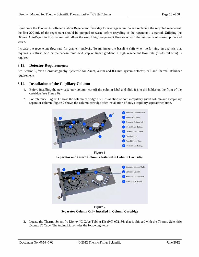
3.14. Installation of the Capillary Column 1. Before installing the new separator column, cut off the column label and slide it into the holder on the front of the
cartridge (see Figure 6).
2. For reference, Figure 1 shows the column cartridge after installation of both a capillary guard column and a capillary separator column. Figure 2 shows the column cartridge after installation of only a capillary separator column.
Figure 1
Separator and Guard Columns Installed in Column Cartridge
Figure 2
Separator Column Only Installed in Column Cartridge
3. Locate the Thermo Scientific Dionex IC Cube Tubing Kit (P/N 072186) that is shipped with the Thermo Scientific Dionex IC Cube. The tubing kit includes the following items:
Separator Column Outlet
Separator Column
Separator Column Inlet
Precision Cut Tubing
Guard Column Outlet
Guard Column
Guard Column Inlet
Precision Cut Tubing
1
2
3
4
5
6
7
8
1
2
34
5
6
7
8
Separator Column Outlet
Separator Column
Separator Column Inlet
Precision Cut Tubing
1
2
3
4
1
2
3 4

Product Manual for Thermo Scientific Dionex IonPac™ CS19 Column Page 14 of 58
Document No. 065440-02 © 2012 Thermo Fisher Scientific June 2012
Table 3 Contents of the Dionex IC Cube Tubing Kit (P/N 072186)
Part Number
Part Length / Quantity
Used To Connect…
072188 Precision cut 0.062-mm (0.0025-in) ID PEEK tubing, blue
65 mm (2.56 in)
50 mm guard column outlet to 250 mm separator column inlet
072189 Precision cut 0.062-mm (0.0025-in) ID PEEK tubing, blue, labeled VALVE PORT 3
115 mm (4.53 in)
Guard column inlet to injection valve
074603 Precision cut 0.062-mm (0.0025-in) ID PEEK tubing, blue
75 mm (2.93 in)
35 mm guard column outlet to 150 mm separator column inlet
072187 Precision cut 0.062-mm (0.0025-in) ID PEEK tubing, blue, labeled VALVE PORT 3
210 mm (8.27 in)
Separator column inlet to injection valve (if a guard column is not present)
042690 0.25-mm (0.010-in) ID PEEK tubing, black
610 mm (24 in)
EG degas cartridge REGEN OUT to waste (if an EG is not present)
072949 Fitting bolt, 10-32 hex double-cone (smaller), black
3 Connect precision cut 0.062-mm (0.0025-in) ID PEEK tubing
043275 Fitting bolt, 10-32 double-cone (larger), black
1 Connect 0.25-mm (0.010-in) ID PEEK tubing (black)
043276 Ferrule fitting, 10-32 double-cone, tan
4 Use with both sizes of fitting bolts

Product Manual for Thermo Scientific Dionex IonPac™ CS19 Column Page 15 of 58
Document No. 065440-02 © 2012 Thermo Fisher Scientific June 2012
4. Refer to the following figures for the precision cut tubing required for your configuration:
Figure 3
Tubing Connections for 250-mm Separator Column and 50-mm Guard Column
Figure 4
Tubing Connections for Separator Column Only
5. Lift up the lid of the column cartridge to open it.
6. Remove the fitting plug from the outlet fitting on the separator column. Orient the fitting with a flat side up (see Figure 5) and push the fitting into the opening at the front of the column cartridge until it stops.
Figure 5
Column Outlet Fitting Installed in Column Cartridge
250 mm Separator Column
65 mm (2.56 in)Precision Cut Tubing(P/N 072188)
50 mm Guard Column
115 mm (4.53 in)Precision Cut Tubing(P/N 072189)
1
2
3
41
2
3
4
Separator Column
210 mm (4.5 in)Precision Cut Tubing(P/N 072187)(use with any lengthseperator column)
1
2
1
2

Product Manual for Thermo Scientific Dionex IonPac™ CS19 Column Page 16 of 58
Document No. 065440-02 © 2012 Thermo Fisher Scientific June 2012
NOTE!
7. Coil the separator column tubing inside the cartridge as shown in Figure 1 or Figure 2. Secure the column tubing and the inlet fitting in the clips on the column cartridge.
8. Secure the inlet and outlet fittings on the guard column (if used) in the column clips on the lid of the column cartridge.
9. Route the guard column inlet tubing (if used) or the separator column inlet tubing through the clip on the top edge of the column cartridge lid.
10. Close the lid (you should hear a click) and route the tubing into the slot on the front of the column cartridge (see Figure 6).
If the columns are installed correctly, the cartridge lid snaps closed easily. If the lid does not close easily, do not force it. Open the lid and verify that the columns and tubing are installed correctly and secured in the clips.
Figure 6
Column Cartridge Closed
Separator Column Outlet
Column Inlet Tubing
1
2
1
2

Product Manual for Thermo Scientific Dionex IonPac™ CS19 Column Page 17 of 58
Document No. 065440-02 © 2012 Thermo Fisher Scientific June 2012
SECTION 4 – OPERATION
4.1. General Operating Conditions
Column: 0.4-mm: Dionex IonPac CS19 0.4-mm Capillary Column + Dionex IonPac CG19 0.4-mm Capillary Guard Column
2-mm: Dionex IonPac CS19 2-mm Analytical Column + Dionex IonPac CG19 2-mm Guard Column 4-mm: Dionex IonPac CS19 4-mm Analytical Column + Dionex IonPac CG19 4-mm Guard Column
Sample Volume: 0.4-mm: 0.4 μL Loop 2-mm: 5 µL Loop + 0.8 µL Injection valve dead volume 4-mm: 25 μL Loop + 0.8 μL Injection valve dead volume Eluent: 8 mM Methanesulfonic acid (MSA) Eluent Flow Rate: 0.4-mm: 0.010 mL/min 2-mm: 0.25 mL/min 4-mm: 1.0 mL/min Temperature: 30 °C Dionex SRS Suppressor: Dionex Cation Self-Regenerating Suppressor, Dionex CSRS 300 (2-mm or 4-mm) Dionex Cation Capillary Electrolytic Suppressor, Dionex CCES 300 (0.4-mm) AutoSuppression Recycle Mode or Dionex AES Suppressor: Dionex Cation Atlas Electrolytic Suppressor, Dionex CAES (for 2-mm or 4-mm
only) or Dionex MMS Suppressor: Dionex Cation MicroMembrane Suppressor, Dionex CMMS 300 (for 2-mm or
4-mm only) Dionex MMS Regenerant: TBAOH Dionex CMMS Mode: Dionex Displacement Chemical Regeneration (Dionex DCR) Expected Background Conductivity: < 0.3 µS in the suppressed mode Storage Solution: Eluent
4.2. Dionex IonPac CS19 Operation Precautions
Operate below 3,000 psi (20.68 MPa). Filter and Degas Eluents. Filter Samples. Eluent pH between 0 and 7. Sample pH between 0 and 14. 0.015 mL/min maximum flow rate for 0.4-mm columns. 0.375 mL/min maximum flow rate for 2-mm columns. 1.5 mL/min maximum flow rate for 4-mm columns. Max column oven temperature is < 40 °C
CAUTION!

Product Manual for Thermo Scientific Dionex IonPac™ CS19 Column Page 18 of 58
Document No. 065440-02 © 2012 Thermo Fisher Scientific June 2012
NOTE!
4.3. Chemical Purity Requirements Obtaining reliable, consistent, and accurate results requires eluents that are free of ionic impurities. Chemicals, solvents and deionized water used to prepare eluents must be of the highest purity available. Low trace impurities and low particle levels in eluents also help to protect your ion exchange columns and system components. Thermo Fisher Scientific cannot guarantee proper column performance when the quality of the chemicals, solvents and water used to prepare eluents has been compromised.
4.3.1. Deionized Water The deionized water used to prepare eluents should be Type I Reagent Grade Water with a specific resistance of 18.2 megohm-cm. The deionized water should be free of ionized impurities, organics, microorganisms and particulate matter larger than 0.2 µm. Filter water with a 0.2 µm filter. Bottled HPLC-Grade Water (with the exception of Burdick & Jackson) should not be used since most bottled water contains an unacceptable level of ionic impurities.
4.3.2. Inorganic Chemicals Reagent Grade inorganic chemicals should always be used to prepare ionic eluents. Whenever possible, inorganic chemicals that meet or surpass the latest American Chemical Society standard for purity should be used. These inorganic chemicals will detail the purity by having an actual lot analysis on each label. The following chemicals will perform reliably:
A. Use Fluka or Aldrich Methanesulfonic Acid (MSA) (>99% pure) or Thermo Scientific Dionex Methanesulfonic Acid Concentrate (0.4 M) P/N 057562 or Thermo Scientific Dionex Methanesulfonic Acid (15.4 M) P/N 033478.
B. Use Dionex Cation Regenerant Solution, tetrabutylammonium hydroxide (Dionex TBAOH), P/N 039602, to ensure maximum system performance when operating with a Dionex CMMS 300, or a Dionex CSRS 300 in the Chemical Suppression Mode. For the Dionex DCR Mode, use Dionex TBAOH (P/N 057561).
C. Use deionized water with a specific resistance of 18.2 megohm-cm to make all standards and eluents.
4.3.3. Solvents Solvents can be added to the ionic eluents used with Dionex IonPac CS19 columns to modify the analytes retention in the column, to improve sample solubility, or to clear the column from hydrophobic contaminants. The solvents used must be free of ionic impurities. However, since most manufacturers of solvents do not test for ionic impurities, it is important that the highest grade of solvents available be used. Currently, several manufacturers make ultrahigh purity solvents that are compatible for HPLC and spectrophotometric applications. These ultrahigh purity solvents will usually ensure that your chromatography is not affected by ionic impurities in the solvent. Currently at Thermo Fisher Scientific, we have obtained consistent results using Optima® Solvents by Fisher Scientific. When using a solvent in an ionic eluent, column back pressures will depend on the solvent used, concentration of the solvent, the ionic strength of the eluent, the column, the temperature, and the flow rate used. It is recommended to first add 5% solvent to the eluent and rinse the column with it at half the standard flow rate for 15 minutes. The column back pressure will vary as the composition of water-solvent mixture varies. The practical back pressure limit for the Dionex IonPac CS19 columns is 3,000 psi (20.68 MPa). The Dionex IonPac CS19 is compatible with the HPLC solvents listed in Table 4, “HPLC Solvents for Use with the Dionex IonPac CS19 Columns.” Solvents and water should be premixed in concentrations which allow proper mixing by the pump and to minimize outgassing. Ensure that all of the inorganic chemicals are soluble in the highest solvent concentration to be used during the analysis.
At a characteristic concentration range of organic solvent in the eluent, the column back pressure may more than double. If this is the case, you should decrease the eluent flow rate to allow use of the eluent containing solvent in this concentration range.

Product Manual for Thermo Scientific Dionex IonPac™ CS19 Column Page 19 of 58
Document No. 065440-02 © 2012 Thermo Fisher Scientific June 2012
WARNING!
Table 4 HPLC Solvents for Use with Dionex IonPac CS19 Columns
Solvent Maximum Operating Concentration Acetonitrile 100% Acetone 100% Alcohol 0%
Do NOT use alcohols as an eluent on the Dionex IonPac CS19 column. The Dionex IonPac CS19 Column is compatible with 100% IPA (isopropyl alcohol), but due to the very high backpressure generated in the column at even a very slow flow rate (such as 0.05 mL/minute for the 2x250 mm format), IPA should not be used as an eluent. It is not practical to have it as an eluent component, but IPA could be used for column clean up at very low flow rates or can be present in the sample matrix.
4.4. Preparation of Eluent Stock Solution Concentrates Sulfuric acid (H2SO4) is very corrosive. Methanesulfonic acid (MSA) is also a corrosive and a strong irritant.
Avoid breathing the vapors. Always use these reagents in a fume hood. Wear gloves and goggles.
4.4.1. 1.0 N Methanesulfonic Acid (MSA) Stock Solution A. 1.0 N methanesulfonic acid stock solution can be prepared as follows: B. Weigh out 96.10 g of methanesulfonic acid (MSA, > 99%, P/N 033478). C. Carefully add this amount to a 1-liter volumetric flask containing about 500 mL of deionized water. D. Dilute to the mark and mix thoroughly.
4.4.2. 0.4 N Dionex Methanesulfonic Acid (MSA) Eluent Concentrate 0.4 N Dionex Methanesulfonic Acid Eluent Concentrate (P/N 057562 or package of 4, P/N 057568) is available from Thermo Scientific.
CAUTION!

Product Manual for Thermo Scientific Dionex IonPac™ CS19 Column Page 20 of 58
Document No. 065440-02 © 2012 Thermo Fisher Scientific June 2012
4.4.3. 1.0 N Sulfuric Acid Stock Solution This solution will be used in the preparation of each of the eluents in Section 5, “Example Applications”, when it is designed to replace MSA eluents with sulfuric acid eluents. Calculate the amount (in grams) of concentrated sulfuric acid (H2SO4) that you need to add to a 1 liter volumetric flask by using the % H2SO4 composition stated on the label of the particular bottle of H2SO4 you are using. For example, if the H2SO4 concentration is 98%, you need to weigh out 50.04 grams of concentrated H2SO4. Carefully add this amount of H2SO4 to a 1- liter volumetric flask containing about 500 mL of deionized water with a specific resistance of 18.2 megohm-cm. Dilute to the 1 liter mark and mix thoroughly. In other words: 1M H2SO4 = 2.0 N H2SO4 FW of H2SO4 = 98.08 g H2SO4 concentration = 98% Therefore, to prepare 1 L of a 1 N H2SO4 solution, weigh out: 1 liter x 98.08 g x 1 mole x 1 mole x 100 g = 50.04 g 1 mole 2 Eq 1 liter 98 g
4.4.4. Eluent Preparation Eluent: X mN Sulfuric Acid (H2SO4) or Methanesulfonic acid (MSA) Using the table below, pipet x.0 mL of the 1.0 N H2SO4 or 1.0 N MSA eluent concentrate (see Section 5.1, “Preparation of Eluent Stock Solution Concentrates”) into a 1-L volumetric flask. Dilute to 1-L using deionized water with a specific resistance of 18.2 megohm-cm. Degas the eluent.
Table 5 mN Eluents from Stock Solutions
MSA/H2SO4
mN
#mL 4 4.0
10 10.0 16 16.0 18 18.0 20 20.0 22 22.0 24 24.0 30 30.0 40 40.0
100 100.0

Product Manual for Thermo Scientific Dionex IonPac™ CS19 Column Page 21 of 58
Document No. 065440-02 © 2012 Thermo Fisher Scientific June 2012
NOTE!
4.5. Making and Using Eluents that Contain Solvents
When purging or degassing eluents containing solvents, do not purge or degas the eluent excessively since it is possible that a volatile solvent can be "boiled" off from the solution. Always degas and store all eluents in plastic eluent bottles pressurized with helium. Only helium can be used to purge and degas ionic eluents containing solvents, since nitrogen is soluble in solvent containing eluents.
When mixing solvents with water remember to mix solvent with water on a volume to volume basis. If a procedure requires an eluent of 20% acetonitrile, prepare the eluent by adding 200 mL of acetonitrile to an eluent reservoir. Then add 100 mL of deionized water at a time to the acetonitrile in the reservoir and fill it up to the 1 liter mark. Using this procedure to mix solvents with water will ensure that a consistent true volume/volume eluent is obtained. Premixing water with solvent will minimize the possibility of outgassing. Avoid creating high viscosity pressure fronts that may disrupt the column packing when the eluent solvent component is added or changed. To do this, equilibrate the column at half its standard flow rate for approximately 10 minutes with an eluent containing only 5% of the current solvent type. Exchange this eluent for an eluent with 5% of the new solvent type and then equilibrate the column and allow the system to stabilize (approximately 10 minutes). Next run a 15-minute gradient from 5% of the new solvent type to the highest percentage that will be used during the new analysis protocol. Properly equilibrate the column when changing to a solvent-free eluent system after using eluents containing solvent. First equilibrate the column with 1 to 5 percent of the current solvent for approximately 5 minutes. Next run a 10-minute gradient from the eluent with 1 to 5 percent of the current solvent to the new solvent free aqueous eluent. The Dionex Cation Self-Regenerating Cation Suppressor (Dionex CSRS 300) must be operated in the AutoSuppression External Water Mode when using eluents containing solvents. The Chemical Suppression Mode is recommended for long term trouble free operation.
Acetonitrile is not compatible with the Dionex Cation Regenerant Cartridge when using a Dionex AutoRegen Accessory Unit. The acetonitrile diffuses into the TBAOH regenerant, concentrates during recirculation and eventually hydrolyzes to acetate and ammonia, depleting the capacity of the Dionex AutoRegen Cation Regenerant Cartridge. If acetonitrile is used with suppressed conductivity, a pressurized vessel rather than the Dionex AutoRegen must be used. CAUTION
!

Product Manual for Thermo Scientific Dionex IonPac™ CS19 Column Page 22 of 58
Document No. 065440-02 © 2012 Thermo Fisher Scientific June 2012
SECTION 5 – EXAMPLE APPLICATIONS
5.1. Isocratic Elution of the Common Six Cations using the Dionex IonPac CS19 (2x250 mm), with/without Dionex IonPac CG19 (2x50 mm)
The chromatograms below show suppressed conductivity detection and separation of the common cations plus ammonium ion using the Dionex IonPac CS19 column with and without a Dionex IonPac CG19 guard column. As can be seen, the Dionex IonPac CG19 guard column has much lower capacity per gram of resin than the Dionex IonPac CS19 separator, and adds only about 0.5 minutes to the total retention time when it is used. It is purposely made of lower cation exchange capacity so that its pressure contribution is small (should be less than 200 psi). Column: see chromatograms Eluent Source: Dionex EGC II MSA cartridge Eluent: 8 mM MSA Flow Rate: 0.25 mL/min Injection volume: 5 µL Temperature: 30 ºC Detection: Suppressed Conductivity, Dionex CSRS 300, AutoSuppression, recycle mode
Figure 7 Isocratic Elution of the Common Six Cations using the Dionex IonPac CS19,
with/without Dionex IonPac CG19 (2-mm)
12 3
4 5 6
6543
21
Dionex IonPac CS19 2x250 mm
Dionex IonPac CG19 2x50 mm
Dionex IonPac CS19 2x250 mm
0 3 6 9 12 15
0
3
µS
Minutes
0 3 6 9 12 150
2.5
µS
Minutes
Peaks mg/L 1. Lithium 0.25 2. Sodium 1.00 3. Ammonium 1.25 4. Potassium 2.5 5. Magnesium 1.25 6. Calcium 2.5 NOTE: Concentrations are only approximate.

Product Manual for Thermo Scientific Dionex IonPac™ CS19 Column Page 23 of 58
Document No. 065440-02 © 2012 Thermo Fisher Scientific June 2012
5.2. Isocratic Elution of the Common Six Cations using the Dionex IonPac CS19 (0.4x250 mm), with/without Dionex IonPac CG19 (0.4x50 mm)
Column: See chromatograms Eluent Source: Dionex EGC II MSA cartridge Eluent: 8 mM MSA Flow Rate: 0.010 mL/min Injection volume: 400 nL Temperature: 30ºC Detection: Suppressed Conductivity, Dionex CCES 300, AutoSuppression, recycle mode
Figure 8 Isocratic Elution of the Common Six Cations using the Dionex IonPac CS19 (0.4x250 mm),
with/without Dionex IonPac CG19 (0.4x50 mm
0 3 6 9 12 15
0
3
µS
Minutes
CG19 0.4x50 mmCS19 0.4x250 mm
1
2 3
4
5
6
CS19 0.4x250 mm
1
2 3
4
56
0 3 6 9 12 15
0
3
µS
Minutes
Peaks mg/L 1. Lithium 0.125 2. Sodium 0.50 3. Ammonium 0.625 4. Potassium 1.25 5. Magnesium 0.625 6. Calcium 1.25 NOTE: Concentrations are only approximate.

Product Manual for Thermo Scientific Dionex IonPac™ CS19 Column Page 24 of 58
Document No. 065440-02 © 2012 Thermo Fisher Scientific June 2012
5.3. Isocratic Elution of Group I & Group II Cations plus Ammonium using the Dionex IonPac CG19 and the Dionex IonPac CS19 Columns (2x250 mm)
This chromatogram was run isocratically with 7 mM methanesulfonic acid concentration; the monovalent cations elute first followed by divalent cations. Columns: Dionex IonPac CG19/CS19 (2 mm) Eluent Source: Dionex EGC II MSA cartridge Eluent: 7 mM MSA Flow Rate: 0.25 mL/min Injection volume: 5 µL Temperature: 30 ºC Detection: Suppressed Conductivity, Dionex CSRS 300, AutoSuppression, recycle mode
Figure 9 Isocratic Elution of Group I and Group II Cations Plus Ammonium
with Dionex IonPac CG19/CS19 (2-mm)
0 4 8 12 16 20 24 28
0
1.20
µS
Minutes
2
1
3
4
5
6
7
8
9
10
Peaks mg/L 1. Lithium 0.15 2. Sodium 0.60 3. Ammonium 0.75 4. Potassium 1.5 5. Rubidium 1.2 6. Cesium 1.4 7. Magnesium 0.75 8. Calcium 1.5 9. Strontium 1.4 10. Barium 1.4 NOTE: Concentrations are only approximate. The peaks between # 5 and # 6, and between peak # 7 and # 8 are unknown.

Product Manual for Thermo Scientific Dionex IonPac™ CS19 Column Page 25 of 58
Document No. 065440-02 © 2012 Thermo Fisher Scientific June 2012
5.4. Separation of Six Common Cations plus Ethylamines using the Dionex IonPac CG19 and the Dionex IonPac CS19 (2x250 mm)
The example below shows the separation of common cations from ethylamine, diethylamine and triethylamine using the Dionex IonPac CS19 column. These amines can be separated from the common six cations using an isocratic eluent and slightly elevated temperature. Columns: Dionex IonPac CG19/CS19 (2 mm) Eluent Source: Dionex EGC II MSA cartridge Eluent: 4 mM MSA Flow Rate: 0.25 mL/min Injection volume: 5 µL Temperature: 30 ºC Detection: Suppressed Conductivity Dionex CSRS 300 AutoSuppression, recycle mode
Figure 10 Separation of Six Common Cations plus Ethylamines
using the Dionex IonPac CG19/CS19 (2-mm)
0.0 6 12 18 24 30
0
3
µS
Minutes
2
1
3
4
5
6
78
9
Peaks mg/L 1. Lithium 0.125 2. Sodium 0.5 3. Ammonium 0.62 4. Ethylamine 0.7 5. Potassium 1.25 6. Diethylamine 0.7 7. Magnesium 0.62 8. Triethylamine 7.0 9. Calcium 1.25 NOTE: Concentrations are only approximate.

Product Manual for Thermo Scientific Dionex IonPac™ CS19 Column Page 26 of 58
Document No. 065440-02 © 2012 Thermo Fisher Scientific June 2012
5.5. Gradient Elution of Six Common Cations plus Methylamines using the Dionex IonPac CS19 (2x250 mm)
Using the “standard eluent conditions”, the six common cations can be separated from methylamine and trimethylamine, however potassium and dimethylamine coelute. To resolve potassium from dimethylamine, the column temperature needs to be increased to 40°C. The effect of temperature on potassium is higher than on dimethylamine, causing the potassium to elute earlier and be resolved from the dimethylamine. Thus, it is possible to resolve the common six cations from methyl-, dimethyl- and trimethylamine on the Dionex IonPac CS19 using a gradient eluent at 40 °C. Column: Dionex IonPac CS19 (2x250 mm) Eluent Source: Dionex EGC II MSA cartridge Eluent: Isocratic 1.7 mM MSA from 0 to 12 minutes, gradient to 11 mM MSA from 12 to 16 minutes, isocratic to 25 minutes, back to 1.7 mM MSA at 25.1 minutes. Flow Rate: 0.25 mL/min Injection volume: 5 µL Temperature: 40 ºC Detection: Suppressed Conductivity, Dionex CSRS 300, AutoSuppression, recycle mode
Figure 11 Gradient Elution of Six Common Cations plus Methylamines
using the Dionex IonPac CS19 (2-mm)
0 6 12 18 24 30
0
1.40
µS
Minutes
1 2
3
4
5
67
8
9
Peaks m/L 1. Lithium 0.1 2. Sodium 0.4 3. Ammonium 0.5 4. Methylamine 0.5 5. Potassium 1.0 6. Dimethylamine 0.4 7. Trimethylamine 1.5 8. Magnesium 0.5 9. Calcium 1.0 NOTE: Concentrations are only approximate.

Product Manual for Thermo Scientific Dionex IonPac™ CS19 Column Page 27 of 58
Document No. 065440-02 © 2012 Thermo Fisher Scientific June 2012
5.6. Separation of Six Common Cations plus Methylamines using the Dionex IonPac CS19 (4x250 mm)
This examples shows the separation of six common cations plus methylamines using the Dionex IonPac CS19 4mm column. Using the “standard eluent conditions”, the six common cations can be separated from methylamine and trimethylamine, however potassium and dimethylamine coelute. To resolve potassium from dimethylamine, the column temperature needs to be increased to 40 °C. The effect of temperature on potassium is higher than on dimethylamine, causing the potassium to elute earlier and be resolved from the dimethylamine. Thus, it is possible to resolve the common six cations from methyl-, dimethyl- and trimethylamine on the Dionex IonPac CS19 using a gradient eluent at 40 °C. Columns: Dionex CS19 (4x250 mm) Eluent: Isocratic 1.7 mM MSA, gradient to 11 mM MSA from 12 to 16 minutes, isocratic to 25 minutes, back to 1.7 mM MSA at 25.1 minutes. Eluent Source: Dionex EGC II MSA cartridge Injection volume: 25 µL Flow Rate: 1.0 mL/min Temperature: 40°C Detection: Suppressed Conductivity, Dionex CSRS 300, AutoSuppression, recycle mode
Figure 12 Separation of Six Common Cations plus Methylamines
using the Dionex IonPac CS19 (4x250 mm)
1 23
4
5
67
89
0 4 8 12 16 20 24 28
0
2.5
µS
Minutes
Peaks m/L 1. Lithium 0.1 2. Sodium 0.4 3. Ammonium 0.5 4. Methylamine 0.5 5. Potassium 1.0 6. Dimethylamine 0.4 7. Trimethylamine 1.5 8. Magnesium 0.5 9. Calcium 1.0 NOTE: Concentrations are only approximate.

Product Manual for Thermo Scientific Dionex IonPac™ CS19 Column Page 28 of 58
Document No. 065440-02 © 2012 Thermo Fisher Scientific June 2012
5.7. Isocratic Elution of the Six Common Cations plus Alkanolamines using the Dionex IonPac CG19/CS19 (2x250 mm)
The chromatogram below shows the separation of the common cations plus alkanolamines using suppressed conductivity. These amines can be found together in the chemical and power industries, as impurities or as decomposition products of larger amines. Monoethanolamine is one of the most important corrosion inhibitors utilized on the Power Industry and generally needs to be quantified together with very low levels of sodium and high or low levels of ammonium ion. The Dionex IonPac CS19 column also offers good selectivity for diethanolamine and triethanolamine as well as the common cations. Using an isocratic eluent containing 4 mM MSA will resolve these ions. Column: Dionex IonPac CG19/CS19 (2 mm) Eluent Source: Dionex EGC II MSA cartridge Eluent: 4 mM MSA Flow Rate: 0.25 mL/min Injection volume: 5 µL Temperature: 30 ºC Detection: Suppressed Conductivity, Dionex CSRS 300, AutoSuppression, recycle mode
Figure 13 Isocratic Elution of the Six Common Cations plus Ethanolamines
using the Dionex IonPac CG19/CS19 (2-mm)
0 5 10 15 20 25 30 35 40
0
2.0
µS
Minutes
1
2
3 4
56
78 9
Peaks mg/L 1. Lithium 0.125 2. Sodium 0.5 3. Ammonium 0.62 4. Ethanolamine 5.0 5. Diethanolmine 10.0 6. Potassium 1.25 7. Triethanolamine 45.0 8. Magnesium 0.62 9. Calcium 1.25 NOTE: Concentrations are only approximate. The peaks between peak # 7 and # 8 are unknown.

Product Manual for Thermo Scientific Dionex IonPac™ CS19 Column Page 29 of 58
Document No. 065440-02 © 2012 Thermo Fisher Scientific June 2012
5.8. Separation of Six Common Cations plus Biogenic Amines using the Dionex IonPac CS19 (4x250 mm)
This example shows the separation of six common cations plus biogenic amines using the Dionex IonPac CS19 4 mm column. An organic-solvent-free eluent is used to elute the polyvalents spermidine and spermine from this column, with the help of a higher acidic eluent concentration. Notice the flat baseline in-spite of the eluent gradient conditions. Columns: Dionex IonPac CS19 (4x250 mm) Eluent: 8 mM MSA isocratic to 7 min, gradient to 40 mM MSA at 13 minutes, gradient to 60 mM MSA at 20 minutes, back to 8 mM MSA at 20.1 minutes Eluent Source: Dionex EGC II MSA cartridge Injection volume: 25 µL Flow Rate: 1.20 mL/min Temperature: 30 °C Detection: Suppressed Conductivity, Dionex CSRS 300, AutoSuppression, recycle mode
Figure 14 Separation of Six Common Cations plus Biogenic Amines
using the Dionex IonPac CS19 (4x250 mm)
0 4 8 12 16 20 24
0
6
Minutes
µS
21
435
6
8
7
10
9
11 12
Peaks 1. Lithium 2. Sodium 3. Ammonium 4. Potassium 5. Magnesium 6. Calcium 7. Putrescine 8. Cadaverine 9. Histamine 10. Agmatine 11. Spermine 12. Spermidine

Product Manual for Thermo Scientific Dionex IonPac™ CS19 Column Page 30 of 58
Document No. 065440-02 © 2012 Thermo Fisher Scientific June 2012
5.9. Separation of Six Common Cations plus Biogenic Amines using the Dionex IonPac CG19/CS19 (2x250 mm)
The amines shown here separated on the Dionex IonPac CS19 are of interest in the Food Industry. For example, histamine is formed by bacterial decomposition of histidine, and is important to determine its content in wine. The freshness of seafood and meat products is determined by the amounts of biogenic amines present. An organic-solvent-free eluent is used to elute the polyvalents spermidine and spermine from this column, with the help of a higher acidic eluent concentration. Notice the flat baseline in-spite of the eluent gradient conditions. Columns: Dionex IonPac CG19/CS19 (2 mm) Eluent Source: Dionex EGC II MSA cartridge Eluent: 8 mM MSA isocratic to 7 min, gradient to 40 mM MSA at 13 minutes, gradient to 60 mM MSA at 20 minutes, back to 8 mM MSA at 20.1 minutes Flow Rate: 0.30 mL/min Injection volume: 5 µL Temperature: 30 ºC Detection: Suppressed Conductivity. Dionex CSRS 300, AutoSuppression, recycle mode
Figure 15 Separation of Six Common Cations plus Biogenic Amines
using the Dionex IonPac CG19/CS19 (2-mm)
0 4 8 12 16 20 24
0
14
µS
Minutes
123 4 5 6
7
8
9
10
11 12
Peaks mg/L 1. Lithium 0.1 2. Sodium 0.4 3. Ammonium 0.5 4. Potassium 1.0 5. Magnesium 0.5 6. Calcium 1.0 7. Putrescine 15 8. Cadaverine 9 9. Histamine 13 10. Agmatine 20 11. Spermine 3 12. Spermidine 6 NOTE: Concentrations are only approximate

Product Manual for Thermo Scientific Dionex IonPac™ CS19 Column Page 31 of 58
Document No. 065440-02 © 2012 Thermo Fisher Scientific June 2012
5.10. Fast Separation of Six Common Cations plus Biogenic Amines using the Dionex IonPac CG19/CS19 (2 x 250 mm)
Elution of the biogenic amines can be faster by using higher eluent concentrations and a faster flow rate. See chromatogram below. Column: Dionex IonPac CG19/CS19 (2 mm) Eluent Source: Dionex EGC II MSA cartridge Eluent: 9 mM MSA gradient to 70 mM MSA in 10 minutes, Isocratic to 11 minutes, back to 9 mM MSA at 11.1 minutes Flow Rate: 0.35 mL/min Injection volume: 5 µL Temperature: 30ºC Detection: Suppressed Conductivity, Dionex CSRS 300, AutoSuppression, recycle mode
Figure 16 Fast Separation of Six Common Cations plus Biogenic Amines
using the Dionex IonPac CG19/CS19 (2 x 250 mm)
0 2 4 6 8 10 12
0
14
µS
Minutes
1 23 4 5 6
7
8
9
10
1112
Peaks mg/L 1. Lithium 0.1 2. Sodium 0.4 3. Ammonium 0.5 4. Potassium 1.0 5. Magnesium 0.5 6. Calcium 1.0 7. Putrescine 15 8. Cadaverine 9 9. Histamine 13 10. Agmatine 20 11. Spermine 3 12. Spermidine 6 NOTE: Concentrations are only approximate.

Product Manual for Thermo Scientific Dionex IonPac™ CS19 Column Page 32 of 58
Document No. 065440-02 © 2012 Thermo Fisher Scientific June 2012
5.11. Separation of Six Common Cations plus Biogenic Amines using the Dionex IonPac CS19 (0.4x250 mm)
This example shows the separation of six cations plus biogenic amines using the Dionex IonPac CS19 capillary column. Columns: Dionex IonPac CS19 (0.4x250 mm) Eluent: 8 mM MSA isocratic to 7 min, gradient to 40 mM MSA at 13 minutes, gradient to 60 mM MSA at 25 minutes, back to 8 mM MSA at 25.1 minutes Eluent Source: Dionex EGC II MSA cartridge Injection volume: 400 nL Flow Rate: 12 µL/min Temperature: 30°C Detection: Suppressed Conductivity, Dionex CSRS 300 AutoSuppression, recycle mode
Figure 17 Separation of Six Common Cations plus Biogenic Amines
using the Dionex IonPac CS19 (0.4x250 mm)
0 4 8 12 16 20 25
0
9
µS
Minutes
45 6
7
9
10
11
8
122 31
Peaks 1. Lithium 2. Sodium 3. Ammonium 4. Potassium 5. Magnesium 6. Calcium 7. Putrescine 8. Cadaverine 9. Histamine 10. Agmatine 11. Spermine 12. Spermidine

Product Manual for Thermo Scientific Dionex IonPac™ CS19 Column Page 33 of 58
Document No. 065440-02 © 2012 Thermo Fisher Scientific June 2012
5.12. Separation of Six Common Cations, Methylamines and Imidazoles using the Dionex IonPac CS19 (2x250mm)
The caramel color in foodstuffs such as colas is the byproduct of a pressurized treatment that combines sugar with ammonia, leaving behind 2- and 4- methylimidazoles. California has already added 4-methylimidazole to its list of chemicals known to cause cancer. The chromatogram below shows the separation of common cations, methylamines, and imidazoles using the Dionex IonPac CS19 with a gradient eluent and elevated temperature. Column: Dionex IonPac CS19 (2 mm) Eluent Source: Dionex EGC II MSA cartridge Eluent: Isocratic 1.7 mM MSA, gradient to 7 mM MSA From 9 to 13 minutes, isocratic to 25 minutes, back to 1.7 mM MSA at 25.1 minutes. Flow Rate: 0.25 mL/min Injection volume: 5 µL Temperature: 40ºC Detection: Suppressed Conductivity, Dionex CSRS 300 AutoSuppression, recycle mode
Figure 18 Separation of Six Common Cations plus Ethylamines
using the Dionex IonPac CS19 Column
1
2
3
4
5
6 7
8
9
1011
0 6 12 18 24 30
0
1.0
µS
Minutes
Peaks mg/L 1. Lithium 0.03 2. Sodium 23.9 3. Ammonium 0.17 4. Methylamine 0.17 5. Potassium 0.33 6. Dimethylamine 0.13 7. Trimethylamine 0.5 8. 2-methyl imidazole 6.7 9. 4-methyl imidazole 5.3 10. Magnesium 0.17 11. Calcium 0.33 NOTE: Concentrations are only approximate

Product Manual for Thermo Scientific Dionex IonPac™ CS19 Column Page 34 of 58
Document No. 065440-02 © 2012 Thermo Fisher Scientific June 2012
5.13. Separation of Six Common Cations plus Paraquat and Diquat using the Dionex IonPac CS19 (2x250mm)
Paraquat and Diquat are non-selective cationic contact herbicides, commonly used in commercial weed killer formulations for domestic weed control. Paraquat, an analog of Diquat, is a pesticide of high toxicity to humans. The chromatogram below shows the separation of the six common cations from paraquat and diquat using the Dionex IonPac CS19 with gradient elution. Columns: Dionex IonPac CS19 (2x250 mm) Eluent Source: Dionex EGC II MSA cartridge Eluent: Isocratic 8 mM MSA, gradient to 45 mM MSA from 5 to15 minutes, isocratic to 35 minutes, back to 8 mM MSA at 35.1 minutes Flow Rate: 0.25 mL/min Injection volume: 5 µL Temperature: 30ºC Detection: Suppressed Conductivity, Dionex CSRS 300, AutoSuppression, recycle mode
Figure 19 Separation of Six Common Cations plus Paraquat and Diquat
using the Dionex IonPac CS19 (2-mm)
0 10 20 30 40
0
1.2
µS
Minutes
1
2
3
4
5
6
7
8
Peaks mg/L 1. Lithium 0.1 2. Sodium 0.4 3. Ammonium 0.5 4. Potassium 1.0 5. Magnesium 0.5 6. Calcium 1.0 7. Diquat 10.0 8. Paraquat 5.0 NOTE: Concentrations are only approximate

Product Manual for Thermo Scientific Dionex IonPac™ CS19 Column Page 35 of 58
Document No. 065440-02 © 2012 Thermo Fisher Scientific June 2012
5.14. Separation of Six Common Cations plus Paraquat and Diquat using the Dionex IonPac CS19 (4x250mm)
Paraquat and Diquat are non-selective cationic contact herbicides, commonly used in commercial weed killer formulations for domestic weed control. Paraquat, an analog of Diquat, is a pesticide of high toxicity to humans. The chromatogram below shows the separation of the six common cations from paraquat and diquat using the Dionex IonPac CS19 4 mm column with gradient elution. Columns: Dionex IonPac CS19 (4x250 mm) Eluent: Isocratic 8 mM MSA, gradient to 45 mM MSA from 5 to15 minutes, isocratic to 35 minutes, back to 8 mM MSA at 35.1 minutes. Eluent Source: Dionex EGC II MSA cartridge Injection volume: 25 µL Flow Rate: 1.0 mL/min Temperature: 30 °C Detection: Suppressed Conductivity, Dionex CSRS 300, AutoSuppression, recycle mode
Figure 20 Separation of Six Common Cations plus Paraquat and Diquat
using the Dionex IonPac CS19 (4-mm)
0 5 10 15 20 25 30 35 40
0
3
µS
Minutes
23
4
5
6
78
1
Peaks mg/L 1. Lithium 0.1 2. Sodium 0.4 3. Ammonium 0.5 4. Potassium 1.0 5. Magnesium 0.5 6. Calcium 1.0 7. Diquat 10.0 8. Paraquat 5.0 NOTE: Concentrations are only approximate.

Product Manual for Thermo Scientific Dionex IonPac™ CS19 Column Page 36 of 58
Document No. 065440-02 © 2012 Thermo Fisher Scientific June 2012
5.15. Fast Separation of Six Common Cations plus Paraquat and Diquat using the Dionex IonPac CS19 (4x250mm)
Elution of the six cations, paraquat and diquat can be faster by using higher eluent concentrations and a faster flow rate as shown in the chromatogram below. Columns: Dionex IonPac CS19 (4x250 mm) Eluent: Isocratic 8 mM MSA, gradient to 45 mM MSA from 4 to 7 minutes, gradient to 65 mM MSA at 11 minutes, Isocratic to 15 minutes, back to 8 mM MSA at 15.1 minutes. 8 mM MSA at 35.1 minutes. Eluent Source: Dionex EGC II MSA cartridge Injection volume: 25 µL Flow Rate: 1.3 mL/min Temperature: 30 °C Detection: Suppressed Conductivity, Dionex CSRS 300, AutoSuppression, recycle mode
Figure 21 Fast Separation of Six Common Cations plus Paraquat and Diquat
using the Dionex IonPac CS19 (4-mm)
34
5
6
7
8
21
0 5 10 15 20
0
4
µS
Minutes
Peaks mg/L 1. Lithium 0.1 2. Sodium 0.4 3. Ammonium 0.5 4. Potassium 1.0 5. Magnesium 0.5 6. Calcium 1.0 7. Diquat 10.0 8. Paraquat 5.0 NOTE: Concentrations are only approximate.

Product Manual for Thermo Scientific Dionex IonPac™ CS19 Column Page 37 of 58
Document No. 065440-02 © 2012 Thermo Fisher Scientific June 2012
SECTION 6 – TROUBLESHOOTING GUIDE The purpose of the Troubleshooting Guide is to help you solve operating problems that may arise while using Dionex IonPac CS19 columns. For more information on problems that originate with the Ion Chromatograph (IC) or suppressor, refer to the Troubleshooting Guide in the appropriate operator’s manual. If you cannot solve the problem on your own, contact technical support for Dionex Products. In the U.S., call 1-800-346-6390. Outside the U.S., call the nearest Thermo Fisher Scientific office.
Table 6 CS19/CG19 Troubleshooting Summary
Observation Cause Action Reference Section High Back Pressure Unknown component Isolate blockage 6.1.1 Plugged column bed supports Replace bed supports 6.1.2 Plugged system hardware Unplug, Replace Component manual High Background Conductivity and/or High Noise
Improper Suppressor Operation
CSRS, CCES or CAES Not Suppressing Check current 6.5, Component manual
Check REGEN OUT flow 6.5 D, Component manual Check for leaks 6.5 B, Component manual CMMS not suppressing Check regenerant 6.5 D, Component manual Check AutoRegen cartridge 6.5 F, Component manual Air bubble trapped in CSRS or CAES Remove bubble by loosening
fittings 6.4
Contamination Bad eluents Remake eluents 6.2, 6.4, 6.7 A Contaminated column Clean column 6.3.2, Appendix B Contaminated suppressor Clean suppressor 6.3.1, Component manual Hardware Operation Proportioning valve Service valve Component manual Poor Peak Resolution Poor Efficiency Large system void volumes Replumb system 6.6.1 A, Component manual Sluggish injection valve Service valve 6.6.3 B, Component manual Contaminated or deformed bed support Replace bed support 6.1.2 Column headspace Replace column 6.6.1 B Column overloading Reduce sample size 3.4 Low sample pH Reduce sample size, Dilute
Sample, Use OnGuard II A 3.4
Fronting Peaks Low sample pH Reduce sample size, Dilute Sample, Use OnGuard II A
3.4
Column overload Reduce sample size 3.4 Contaminated or deformed bed support Replace bed support 6.1.2 Column headspace Replace column 6.6.1 B Tailing Peaks Contaminated suppressor Clean suppressor 6.3.1, Component Manual Column overloading
Sluggish injection valve Contaminated sample loop
Reduce sample size Service valve Replace loop
3.4 6.6.3 B, Component Manual
Short Retention Times Flow rate too fast Recalibrate pump 6.6.2 A, Component Manual First peaks elute too fast Equilibrate to first eluent 6.6.3 A Bad eluents Remake eluents 6.6.2 B Column contamination Clean column 6.6.2 C Spurious Peaks Eluent contamination
Column contamination Remake eluents Clean Column
6.7 A, 6.2, 6.4 6.3.2 , 6.7 B
Sluggish injection valve Service valve 6.7 C, Component Manual Poor Qualifications of Divalents
Sample loop contamination Suppressor Contamination
Flush, replace Clean Suppressor
6.3.3 6.3.1 , Component Manual

Product Manual for Thermo Scientific Dionex IonPac™ CS19 Column Page 38 of 58
Document No. 065440-02 © 2012 Thermo Fisher Scientific June 2012
6.1. High Back Pressure 6.1.1. Finding the Source of High System Pressure Total system pressure for the Dionex IonPac CG19 Guard/Capillary Guard Column plus the CS19 Analytical/Capillary Column when using the test chromatogram conditions should be below 2,000 psi. If the system pressure is approximately 100 psi higher than this, it is advisable to determine the cause of the high system pressure. The system should be operated with a High-Pressure In-Line Filter (P/N 044105) which is positioned between the Gradient Pump pressure transducer and the injection valve.
A. Make sure that the pump is set to the correct eluent flow rate. Higher than recommended eluent flow rates will cause higher pressure. Measure the pump flow rate if necessary with a stop watch and graduated cylinder.
B. Determine which part of the system is causing the high pressure. High pressure could be due to a plugged tubing or tubing with collapsed walls, an injection valve with a clogged port, a column with particulates clogging the bed support, a clogged High-Pressure In-Line Filter, suppressor or the detector cell.
To determine which part of the chromatographic system is causing the problem, disconnect the pump eluent line from the injection valve and turn the pump on. Watch the pressure; it should not exceed 50 psi (0.34 MPa). Continue adding system components (injection valve, column(s), suppressor and detector) one by one, while monitoring the system pressure. The pressure should increase up to a maximum when the Guard/Capillary Guard and Analytical/Capillary columns are connected (see Table 2, “Typical Dionex IonPac CS19/CG19 Operating Back Pressures”).
The Dionex Cation Self-Regenerating Suppressor 300 may add up to 100 psi (0.69 MPa) of back pressure. No other components should add more than 100 psi (0.69 MPa) of pressure. Refer to the appropriate manual for cleanup or replacement of the problem component.
C. Make sure your system does not have extra tubing to increase the back pressure (as needed for the eluent generator to work properly), left over from a previous set up.

Product Manual for Thermo Scientific Dionex IonPac™ CS19 Column Page 39 of 58
Document No. 065440-02 © 2012 Thermo Fisher Scientific June 2012
NOTE!
6.1.2. Replacing Column Bed Support Assemblies (2 mm and 4 mm columns only) If the column inlet bed support is determined to be the cause of the high back pressure, it should be replaced. If the bed support is contaminated and/or deformed, it may be the cause of poor efficiency and/or poor peak shape. To change the inlet bed support assembly, refer to the following instructions, using one of the two spare inlet bed support assemblies included in the Ship Kit.
A. Disconnect the column from the system.
B. Carefully unscrew the inlet (top) column fitting. Use two open-end wrenches.
C. Remove the bed support. Turn the end fitting over and tap it against a benchtop or other hard, flat surface to remove the bed support and seal assembly. If the bed support must be pried out of the end fitting, use a sharp pointed object such as a pair of tweezers, but be careful that you do not scratch the walls of the end fitting. Discard the old bed support assembly.
D. Place a new bed support assembly into the end fitting. Make sure that the end of the column tube is clean and free of any particulate matter so that it will properly seal against the bed support assembly. Use the end of the column to carefully start the bed support assembly into the end fitting.
If the column tube end is not clean when inserted into the end fitting, particulate matter may obstruct a proper seal between the end of the column tube and the bed support assembly. If this is the case, additional tightening may not seal the column but instead damage the column tube or the end fitting.
Dionex IonPac CS19 Dionex IonPac CS19 Dionex IonPac CS19 4-mm Columns 2-mm Columns 0.4-mm Columns Part (P/N) (P/N) (P/N)
Analytical or Capillary Column 076026 076028 076024 Guard Column 076027 076029 076025 Bed Support Assembly 042955 044689 N/A End Fitting 052809 043278 N/A
E. Screw the end fitting back onto the column. Tighten it fingertight, then an additional 1/4 turn (25 in x lb). Tighten further only if leaks are observed.
F. Reconnect the column to the system and resume operation.
Replace the outlet bed support ONLY if high pressure persists after replacement of the inlet fitting.
CAUTION!

Product Manual for Thermo Scientific Dionex IonPac™ CS19 Column Page 40 of 58
Document No. 065440-02 © 2012 Thermo Fisher Scientific June 2012
6.2. Preparation of Eluents A. Make sure that the eluents and regenerant are made correctly.
B. Make sure that the eluents are made from chemicals with the recommended purity.
C. Make sure that the deionized water used to prepare the reagents has a specific resistance of 18.2 megohm-cm.
6.3. Contamination 6.3.1. Suppressor Contamination A contaminated suppressor could be a cause for high background conductivity due to inadequate eluent suppression, as well as a cause for poor divalent peak efficiencies and high divalent peak asymmetries (i.e. tailing peaks). If tailing peaks are observed, test and clean the suppressor.
A. Testing if the suppressor has been contaminated and is the source of poor divalent peaks chromatography: 1. Modify the QAR test chromatogram stated conditions for the particular format CS19 column so that the
suppressor current applied is half of what is stated in the QAR. 2. Without much delay, inject the QAR standard of the six common cations. 3. As soon as the six common cations have eluted, repeat the injection under these new conditions. Save the data.
If you leave the suppressor too long with this reduced current, the background conductivity will start increasing as the lower current is insufficient to regenerate the suppressor.
4. Increase the suppressor current to what is stated in the QAR test chromatogram. 5. Inject the QAR standard of the six common cations. 6. If the peak efficiencies and asymmetries for magnesium and calcium are worse in step 5 than in step 3, this is an
indication that the source is a contaminated suppressor.
B. Cleaning the suppressor: 1. Remove the suspected suppressor from the system. 2. With a piece of tubing, connect the Eluent In port of the suppressor to its Regen OUT port. 3. Connect the Regen In port to a waste line. 4. Connect the Eluent OUT port to a pump with 0.5 M LiOH eluent. If possible, use a different pump than the
analytical pump you are using for the cation columns. 5. For 30 minutes, pump 0.5 M LiOH eluent at twice the “standard” flow rate for the suppressor (0.5 mL/minute
for a 2-mm CSRS, 2 mL/min for a 4-mm CSRS). The contaminants may have been eluted from the suppressor at this point.
6. For another 30 minutes, proceed to rinse the suppressor with DI water, at the same (double) flow rate. 7. The suppressor is now ready to be re-installed and used.

Product Manual for Thermo Scientific Dionex IonPac™ CS19 Column Page 41 of 58
Document No. 065440-02 © 2012 Thermo Fisher Scientific June 2012
6.3.2. A Contaminated Guard or Analytical/Capillary Column Determine if the column is contaminated. Column contamination can lead to a loss of column capacity since all of the cation exchange sites will no longer be available for the sample ions. Polyvalent cations may be concentrating on the column over a series of runs. Remove the Dionex IonPac CG19 Guard and Dionex IonPac CS19 Analytical or Capillary Columns from the system. If the background conductivity decreases, the column(s) is (are) the cause of the high background conductivity. Clean or replace the Dionex IonPac CG19 at the first sign of column performance degradation (compared to the original test chromatogram) to eliminate downtime. Clean the column(s) as instructed in, “Column Cleanup” (See Appendix B, “Column Care”). To make sure that contaminated hardware is not causing the high background, use deionized water with a specific resistance of 18.2 megohm-cm as eluent. The background should be less than 1 µS. If it is not, check the detector/conductivity cell calibration by injecting deionized water directly into it. See the appropriate manual for details.
A. Check for a contaminated Gradient Mixer. Gradient Mixers in the Gradient Pump Module should be flushed thoroughly to remove any contaminant. Chloride containing eluents should not be pumped through the Dionex CSRS 300.
B. Use chemicals and deionized water of the proper purity. Be especially careful to make sure that the recommended chemicals are used. The deionized water should have a specific resistance of 18.2 megohm-cm.
C. The system should be as metal-free as possible. Gripper tubing fittings used in older systems are a potential source for metal contamination of the column. The new Dionex ThermoFlare or PEEK ferrule fittings are preferred. Inspect the eluent pumps periodically for any signs of leakage.
D. Glass eluent reservoirs can be a source of sodium contamination in the eluent. Two-liter polyethylene eluent reservoirs (P/N 039163) are preferred.
E. For EG operation, use a Dionex CR-CTC Trap Column. Install a Dionex CR-CTC Cation Trap Column (P/N 060478) if using an Eluent Generator with Dionex EGC MSA cartridge.
F. Install a Dionex IonPac Cation Trap Column (Dionex CTC-1, P/N 040192). It should be positioned between the pump and the injection valve. It is highly recommended for all cation gradient applications. The Dionex CTC-1 strips the eluent of cation contaminants that will bind strongly to the analytical column resulting in the loss of column capacity and potentially interfering with the desired cation analyses. The Dionex CTC-1 minimizes baseline changes when performing gradient analyses. The Dionex CTC (2-mm), P/N 043132, should be used in 2-mm and 3-mm systems.

Product Manual for Thermo Scientific Dionex IonPac™ CS19 Column Page 42 of 58
Document No. 065440-02 © 2012 Thermo Fisher Scientific June 2012
6.3.3. Sample Loop and/or Tubing Contamination Eluents made with deionized water that is contaminated with bacteria and samples such as humic acids and soil extracts can potentially contaminate eluent lines and sample loops. Weak cation exchange sites are created on (or attached to) the tubing. This can happen to either Tefzel or PEEK tubing. Thus, the sample loop itself can act as a concentrator and depending on the pH of the sample or the standard and the way it is introduced, inaccurate readings for divalent analytes on weak cation exchange resins may be observed.
A. Weak Cation Exchangers Carboxylated resins (used in the Thermo Scientific Dionex IonPac CS12, CS12A, CS14, CS15, CS16, CS17, CS18 and CS19) are weak acid cation exchangers. These resins have high selectivity for hydronium ion and are used with weak acid eluents. When the sample pH is high (pH 5), the weak cation exchange sites on the contaminated tubing are ionized and divalent cations are preferentially retained. When the sample pH is low (< pH 4), these sites are protonated by the sample and rendered inactive, so that the divalent quantification is not affected.
B. Testing for Loop Contamination when Using Carboxylated Cation Exchange Columns
A simple test can be performed (when using a column such as the Dionex IonPac CS19 which contains a carboxylated resin) with methanesulfonic acid or sulfuric acid to see if the sample loop has been contaminated:
1. Prepare a standard containing 0.5 ppm of calcium and add a small amount of 0.2 mM sodium hydroxide so that the final pH of the standard is between 6.5 and 7.5.
2. With the sample loop in the load position, flush the loop with just enough standard to rinse and fill the loop (e.g. if the loop is 25 µL, flush it with no more than 100 µL).
3. Run the standard and record the peak area.
4. Repeat steps 2 and 3, but this time flush the loop with about 5 mL of standard.
5. If after repeating steps 2 through 4, the peak area for calcium recorded in 4 is significantly larger than that in 3, then the sample loop is contaminated and acting as a concentrator.
6. Replace the sample loop with new tubing and repeat this test.
7. If there is still a quantification problem, check other components of the system (tubing, injection valve, detector cell) or call your Dionex Products representative.
If you have a divalent quantification problem in your system but you neither have the time nor replacement parts, you can still get accurate results for divalent cations if any one of the following applies:
1. Your application involves high levels of divalent cations e.g. > 5 ppm calcium; the “concentration error” is small percentage-wise.
2. The pH of your samples and standards is < 4.
3. A constant volume of sample (and standard), only slightly larger than the sample loop, is flushed through the loop at a constant sampling flow rate.

Product Manual for Thermo Scientific Dionex IonPac™ CS19 Column Page 43 of 58
Document No. 065440-02 © 2012 Thermo Fisher Scientific June 2012
6.4. High Background or Noise In a properly working system, the background conductivity using the operating conditions described in Section 4, “Operation,” should be < 0.3 µS with a Dionex suppressor. If the background is low but the system is noisy, an air bubble may be trapped in the suppressor. With the system running, disconnect the ELUENT OUT line from the suppressor and apply pressure to the open port with your gloved finger to dislodge a suspected bubble. Reconnect the line. Do not take too long to do this, as the current is still being applied to the Dionex suppressor and the eluent flow is needed to produce regenerant.
A. Check the conductivity flow cell for bubbles. See the conductivity detector manual for details.
A system with a high background (> 1 µS) will probably also have high noise, resulting in increased detection limits.
B. Make sure that the eluents and regenerant are prepared correctly (see Section 6.2, “Eluent Preparation”).
C. Determine if the columns or system are contaminated (see Section 6.3, “Contamination”).
D. Determine if the Suppressor is the cause of the high background and/or noise. If the above items have been checked and the problem still persists, the suppression system is causing the problem. See Section 6.5, “Suppressor Not Suppressing Properly.”
Typical background conductivity levels, in a properly working system, are shown below:
ELUENT EXPECTED BACKGROUND CONDUCTIVITY
22 mN H2SO4 or 20 mN Methanesulfonic acid < 1 µS 50 mN H2SO4 or Methanesulfonic acid < 2 µS

Product Manual for Thermo Scientific Dionex IonPac™ CS19 Column Page 44 of 58
Document No. 065440-02 © 2012 Thermo Fisher Scientific June 2012
6.5. Suppressor Not Suppressing Properly If the Dionex Cation Self-Regenerating Suppressor, Dionex Cation Capillary Electrolytic Suppressor, Dionex Cation Atlas Electrolytic Suppressor, or the Dionex Cation MicroMembrane Suppressor is causing the problem, refer to the Thermo Scientific Dionex Cation Self-Regenerating Suppressor Product Manual (Document No. 031139), the Thermo Scientific Dionex Cation Atlas Electrolytic Suppressor Product Manual (Document No. 031770), the Thermo Scientific Dionex Cation MicroMembrane Suppressor Product Manual (Document No. 034359), or the Thermo Scientific Dionex Cation Capillary Electrolytic Suppressor Product Manual (Document No. 065386) for detailed troubleshooting assistance.
A. Check that the Dionex CSRS 300 is not in an alarm state.
B. Check for Dionex CSRS 300 leaks.
C. Make sure that the correct back pressure tubing is properly installed after the Dionex CSRS 300.
D. Check the regenerant flow rate at the REGEN OUT port of the Dionex CSRS. Turn the power to the Dionex CSRS off. Measure the regenerant flow rate. If it is being used in the recycle mode, it should be the same flow rate as the eluent (typically 1 mL/min for 4-mm operation or 0.25 mL/min for 2-mm operation or 0.010 mL/min for 0.4-mm operation). If the Dionex CSRS is used in the AutoSuppression External Water Mode, the regenerant flow rate should be 3-5 mL/min (4mm) or 1-2 mL/min (2 mm).
E. Check the eluent flow rate. See if the eluent flow rate is equivalent to the flow rate specified by the analytical protocol. Measure the eluent flow rate after the column using a stopwatch and graduated cylinder. Refer to the Thermo Scientific Dionex Cation Self-Regenerating Suppressor Product Manual (Document No. 031139) or to the Thermo Scientific Dionex Cation MicroMembrane Suppressor Product Manual (Document No. 034359), or the Thermo Scientific Dionex Cation Capillary Electrolytic Suppressor Product Manual (Document No. 065386) for assistance in determining if the eluent is within suppressible limits.
F. If you are using a Dionex AutoRegen Accessory with the Dionex CSRS (in the Chemical Suppression Mode) or the Dionex CMMS, prepare fresh regenerant solution. Test both the suppressor and the Dionex AutoRegen Regenerant Cartridge for contamination.
1. If the background conductivity is high after preparing fresh regenerant and bypassing the Dionex AutoRegen Regenerant Cartridge, you probably need to clean or replace your Dionex CSRS or Dionex CMMS.
2. If the background conductivity is low when freshly prepared regenerant is run through the Dionex CSRS or Dionex CMMS without a Dionex AutoRegen Accessory in-line, test the Dionex AutoRegen Regenerant Cartridge to see if it is expended. Connect the freshly prepared regenerant to the Dionex AutoRegen Regenerant Cartridge. Pump approximately 200 mL of regenerant through the Dionex AutoRegen Regenerant Cartridge to waste before recycling the regenerant back to the regenerant reservoir. If the background conductivity is high after placing the Dionex AutoRegen Accessory in-line, you probably need to replace the Dionex AutoRegen Regenerant Cartridge. Refer to the “Thermo Scientific Dionex AutoRegen Regenerant Cartridge Refill Product Manual” (Document No. 032852) for assistance.

Product Manual for Thermo Scientific Dionex IonPac™ CS19 Column Page 45 of 58
Document No. 065440-02 © 2012 Thermo Fisher Scientific June 2012
NOTE!
Do not recycle the regenerant through the Dionex Cation Regenerant Cartridge if the eluent contains acetonitrile.
G. Non-linear response or loss of sensitivity
Indications of carbonate contamination are:
1. A higher ammonium peak than should be expected.
2. Dips on either side of an analyte peak's base.
Non-linear response or loss of sensitivity may occur when the suppressor is contaminated with carbonate. This contamination is possibly from dissolved carbon dioxide in the DI water. Degassing will help minimize the presence of carbon dioxide in acidic eluents or in DI water. Note, when pressurizing eluent reservoirs on the system use inert gases such as nitrogen (aqueous applications) or helium.
When the Dionex CSRS suppressor is contaminated with carbonate the following treatment is recommended.
1. Push 5 mL of 2 M NaOH (freshly prepared) through the ELUENT IN port and divert a line from the ELUENT
OUT port to waste.
2. Push 10 mL of 2 M NaOH (freshly prepared) through the REGEN IN port and divert a line out from the REGEN OUT port to waste.
3. Allow the suppressor to equilibrate for 20 minutes.
4. Repeat steps 1 and 2 with degassed DI water and reinstall the unit on the system.
5. If problem persists repeat steps 1–4.
6.6. Poor Peak Resolution Poor peak resolution can be due any or all of the following factors. 6.6.1. Loss of Peak Efficiency Throughout the Chromatogram
A. Extra-column effects can result in sample band dispersion, causing loss of peak efficiencies. Make sure you are using PEEK tubing with an i.d. of no greater than 0.010" for 4-mm systems or 0.005" for 2-mm systems to make all eluent liquid line connections between the injection valve and the detector cell inlet. Cut the tubing lengths as short as possible. Check for leaks. Use only precut capillary tubing for capillary systems.
B. Check to see if headspace has developed in the guard or analytical column. This is usually due to improper use of the column such as submitting it to high pressures. Remove the column’s top end fitting (see Section 6.1.2, “Replacing Column Bed Support Assemblies”). If the resin does not fill the column body all the way to the top, it means that the resin bed has collapsed, creating a headspace. The column must be replaced.

Product Manual for Thermo Scientific Dionex IonPac™ CS19 Column Page 46 of 58
Document No. 065440-02 © 2012 Thermo Fisher Scientific June 2012
6.6.2. Loss of Resolution Throughout the Chromatogram Due to Shortened Retention Times Even with adequate system and column efficiency, resolution of peaks will be compromised if analytes elute too fast.
A. Check the flow rate. See if the eluent flow rate is equivalent to the flow rate specified by the analytical protocol. Measure the eluent flow rate after the column using a stopwatch and graduated cylinder.
B. Check to see if the eluent compositions and concentrations are correct. An eluent that is too concentrated will cause the peaks to elute faster. Prepare fresh eluent. If you are using a gradient pump to proportion the eluent, components from two or three different eluent reservoirs, the resulting eluent composition may not be accurate enough for the application. Use one reservoir containing the correct eluent composition to see if this is the problem. This may be a problem when one of the proportioned eluents is less than 5%.
C. Column contamination can lead to a loss of column capacity. This is because all of the cation exchange sites will no longer be available for the sample ions. For example, polyvalent cations from the sample or metals may concentrate on the column. Refer to, “Column Cleanup” (see Appendix B, “Column Care”), for recommended column cleanup procedures.
Possible sources of column contamination are impurities in chemicals and in the deionized water used for eluents or components of the sample matrix. Be especially careful to make sure that the recommended chemicals are used. The deionized water should have a specific resistance of 18.2 megohm-cm.
D. Diluting the eluent will improve peak resolution, but will also increase the analytes’ retention times. If a 10% dilution of the eluent is not sufficient to obtain the desired peak resolution, or if the resulting increase in retention times is unacceptable, clean the column (see Appendix B, “Column Cleanup” in “Column Care”).
After cleaning the column, reinstall it in the system and let it equilibrate with eluent for about 30 minutes. No water wash is necessary. The column is equilibrated when consecutive injections of the standard give reproducible retention times. The original column capacity should be restored by this treatment, since the contaminants should be eluted from the column. If you need assistance in solving resolution problems, contact Technical Support for Dionex Products. In the U.S., call 1-800-346-6390. Outside the U.S., call the nearest Thermo Fisher Scientific Office.
6.6.3. Loss of Early Eluting Peak Resolution Lack of equilibration to the initial eluent or improperly swept out of void volumes are usually the cause of poor resolution or efficiency of peaks eluting near the system void volume compared to the later eluting peaks.
A. Be sure that the column is equilibrated to the initial eluent. Typically, gradient applications require approximately 10 minutes to equilibrate to the initial eluent. The minimum equilibration time can be determined by making successive runs with increasing equilibration times. The column is equilibrated to the initial eluent when additional equilibration time does not increase the runtime of the first eluting peaks.
B. Sluggish operation of the injection valve may be the problem. Check the air pressure and make sure there are no gas leaks or partially plugged port faces. Refer to the valve manual for instructions.
C. Improperly swept out volumes anywhere in the system prior to the guard and analytical columns may be the problem. Swap components, one at a time, in the system prior to the analytical column and test for front-end resolution after every system change.

Product Manual for Thermo Scientific Dionex IonPac™ CS19 Column Page 47 of 58
Document No. 065440-02 © 2012 Thermo Fisher Scientific June 2012
6.7. Spurious Peaks A. Eluents made with chemicals lacking the required purity will contaminate columns rapidly. Remake all stock
solutions and eluents using chemicals that meet the chemical requirements specified in Section 4.3, “Chemical Purity Requirements.” Clean the column as indicated in “Column Cleanup” (see Appendix B, “Column Care”).
B. Spurious peaks may be due to column contamination. If the samples contain an appreciable level of polyvalent cations, polyvalent cations may contaminate the column. As a result, the retention times for the analytes will decrease, and spurious, inefficient peaks can show up at unexpected times. This problem may be solved by increasing the time between analyses or by adding a regeneration step between successive runs to elute polyvalent cationic contaminants off the column before the next sample injection takes place.
C. An injection valve that needs service may produce baseline upsets. This baseline upset can show up as one or multiple peaks of varying size(s) and shape(s). Typically this will occur when the particular valve needs to be cleaned or torqued (see the system manual). Small baseline disturbances at the beginning or at the end of the chromatogram can be overlooked as long as they do not interfere with the quantification of the peaks of interest.

Product Manual for Thermo Scientific Dionex IonPac™ CS19 Column Page 48 of 58
Document No. 065440-02 © 2012 Thermo Fisher Scientific June 2012
6.8. Poor Efficiency Using Capillary Columns Incorrectly installed fittings on capillary tubing can increase void volumes, causing chromatograms with tailing peaks.
Figure 22
Tailing Peaks Caused by Incorrectly Installed Capillary Tubing Fittings
When connecting a capillary tube fitting, make sure that the ferrule and fitting bolt are at least 2 mm (0.1 in) from the end of the tubing before you insert the tubing into the port. Do not place the ferrule and fitting bolt flush with the end of the tubing. Figure 23 illustrates the correct and incorrect placement of the ferrule and fitting bolt on the tubing.
Figure 23
Correct and Incorrect Ferrule and Fitting Bolt Placement for Capillary Tubing Connections
Correct Incorrect2 mm

Product Manual for Thermo Scientific Dionex IonPac™ CS19 Column Page 49 of 58
Document No. 065440-02 © 2012 Thermo Fisher Scientific June 2012
APPENDIX A - QUALITY ASSURANCE REPORT Quality Assurance Report - Dionex IonPac CS19 Analytical Column - 4 x 250 mm Quality Assurance Report - Dionex IonPac CS19 Analytical Column - 2 x 250 mm Quality Assurance Report - Dionex IonPac CS19 Capillary Column - 0.4 x 250 mm

Product Manual for Thermo Scientific Dionex IonPac™ CS19 Column Page 50 of 58
Document No. 065440-02 © 2012 Thermo Fisher Scientific June 2012
Quality Assurance Report - Dionex IonPac CS19 Analytical Column - 4 x 250 mm

Product Manual for Thermo Scientific Dionex IonPac™ CS19 Column Page 51 of 58
Document No. 065440-02 © 2012 Thermo Fisher Scientific June 2012
Quality Assurance Report - Dionex IonPac CS19 Analytical Column - 2 x 250 mm

Product Manual for Thermo Scientific Dionex IonPac™ CS19 Column Page 52 of 58
Document No. 065440-02 © 2012 Thermo Fisher Scientific June 2012
Quality Assurance Report - Dionex IonPac CS19 Capillary Column - 0.4 x 250 mm

Product Manual for Thermo Scientific Dionex IonPac™ CS19 Column Page 53 of 58
Document No. 065440-02 © 2012 Thermo Fisher Scientific June 2012
APPENDIX B - COLUMN CARE
B.1 Recommended Operating Pressures Operating a column above its recommended pressure limit can cause irreversible loss of column performance. The maximum recommended operating pressure for the Dionex IonPac CS19 Analytical, Capillary or Guard Column is 3,000 psi (20.68 MPa).
Do not use alcohols in the eluent. This can significantly increased column back pressures. Do not use the CS19 column with basic eluents.
B.2 Column Start-Up The column is shipped with eluent as the storage solution. This eluent is the same one shown in the test chromatogram. If you plan to use an eluent other than the test eluent, first equilibrate the column with the desired eluent for 30 to 60 minutes. The column is equilibrated when two consecutive injections of the standard produce the same retention times.
B.3 Column Storage The column’s storage solution should be the eluent used for the particular application. If the column will not be used for one week or more, prepare it for long term storage by flushing the column for a few minutes with the eluent. Cap both ends securely, using the plugs supplied with the column.
CAUTION!

Product Manual for Thermo Scientific Dionex IonPac™ CS19 Column Page 54 of 58
Document No. 065440-02 © 2012 Thermo Fisher Scientific June 2012
B.4 Column Cleanup The following column cleanup protocols have been divided into two general isocratic protocols:
A. Acid soluble contaminants B. Hydrophobic cations and organic contaminants.
Always ensure that the cleanup protocol used does not switch between eluents which may create high pressure eluent interface zones in the column. High pressure zones can disrupt the uniformity of the packing of the column bed and irreversibly damage the performance of the column. High pressure zones in the column can be created by pumping successive eluents through the column that are not miscible, that have eluent components in one eluent that will precipitate out in the other eluent or by using an acid eluent followed by a base eluent with may create a neutralization pressure band. The precipitation of the salts in solvents during column rinses can result in very high pressure zones. High viscosity mixing zones can be created between two eluents having solvents with a very high energy of mixing.
When in doubt, always use low eluent flow rate (half of standard flow rate for the particular format), and include short column steps to reduce the solvent content of the eluent to < 5% levels and the ionic strength of the eluent to < 50 mM levels to avoid creating high pressure zones in the column that may disrupt the uniformity of the column packing. This intermediate low concentration step will prevent precipitation or high viscosity zones. Avoid creating high pressure zones in the column that may disrupt the uniformity of the column packing.

Product Manual for Thermo Scientific Dionex IonPac™ CS19 Column Page 55 of 58
Document No. 065440-02 © 2012 Thermo Fisher Scientific June 2012
NOTE!
I. Column Cleanup Procedure for Polyvalent Cations and Acid-Soluble Contaminants or Transition Metals
A. Prepare 500 mL of 1 M HCl for the cleanup solution. Alternatively prepare 500 mM oxalic acid to remove transition metals such as iron or aluminum contamination.
Nitric acid should not be used instead of hydrochloric acid since nitric acid will not effectively remove iron contaminants. Do not clean the column with alcohols or with basic eluents.
B. Disconnect the Suppressor from the Dionex IonPac CS19 Analytical or Capillary Column. If your system is
configured with both a guard column and an analytical/capillary column, place the guard behind the analytical/capillary column in the eluent flow path. Double check that the eluent flows in the direction designated on each of the column labels.
When cleaning an analytical or capillary column and a guard in series, ensure that the guard column is placed after the analytical/capillary column in the eluent flow path. Contaminants that have accumulated on the guard column can be eluted onto the analytical or capillary column and irreversibly damage it. If in doubt, clean each column separately.
DO NOT pump hydrochloric acid through the Dionex CSRS 300 or the CCES 300 suppressor.
C. Set the pump flow rate to 1.0 mL/min for a Dionex IonPac CS19 4-mm Analytical or Guard Column and to 0.25 mL/min for a Dionex IonPac CS19 2-mm Analytical or Guard Column. Set the pump flow rate to 0.010 mL/min for a Dionex IonPac CS19 Capillary or Capillary Guard Column.
D. Rinse the column for 15 minutes with eluent (8 mM MSA) before pumping the chosen cleanup solution over the column.
E. Pump the cleanup solution (1 M HCl or 500 mM oxalic acid) through the column for 60 minutes.
F. Rinse and equilibrate the column(s) with 8 mM MSA eluent for at least 15 minutes before resuming normal operation (send effluent to waste).
G. Reconnect the Suppressor to the Dionex IonPac CS19 Analytical or Capillary Column and place the guard column in line between the injection valve and the analytical or capillary column if your system was originally configured with a guard column.
H. Equilibrate the system with eluent before resuming normal operation.
CAUTION!
CAUTION!

Product Manual for Thermo Scientific Dionex IonPac™ CS19 Column Page 56 of 58
Document No. 065440-02 © 2012 Thermo Fisher Scientific June 2012
II. Hydrophobic Cations and Organic Contaminants
A. Disconnect the analytical/capillary column from the injection valve and the suppressor. Disconnect the Gradient Mixer or the Dionex Cation Trap Column (Dionex CTC-1 or Dionex CR-CTC) from the pump. Connect the Dionex IonPac CS19 Analytical/Capillary Column directly to the pump. Direct the effluent from the analytical/capillary column directly to a waste container.
B. Set the flow rate to 1 mL/min for a Dionex IonPac CS19 4-mm Analytical or Guard Column and to 0.25 mL/min for a Dionex IonPac CS19 2-mm Analytical or Guard Column. Set the pump flow rate to 0.010 mL/min for a Dionex IonPac CS19 Capillary or Capillary Guard Column.
C. Use the following gradient program to remove hydrophobic cations and organic contaminants. Eluent 1: 100 mM HCl Eluent 2: 90% Acetonitrile in deionized water Time (min) % E1 % E2 0.0 100 0 20.0 0 100 25.0 0 100 45.0 100 0 55.0 100 0
D. Rinse the column for 15 minutes with 10 mM HCl before pumping eluent over the column.
E. Rinse and equilibrate the column(s) with 8 mM MSA eluent for at least 30 minutes before resuming normal operation.
F. Reconnect the Dionex IonPac CS19. Connect the Analytical/Capillary Column outlet to the Suppressor and the inlet to either the Dionex IonPac CG19 Guard Column or the Pump Module.
G. Equilibrate the column with eluent before resuming normal operation.

Product Manual for Thermo Scientific Dionex IonPac™ CS19 Column Page 57 of 58
Document No. 065440-02 © 2012 Thermo Fisher Scientific June 2012
APPENDIX C – CONFIGURATION
C.1 Configuration of Ion Chromatography (IC) Systems
Table 7 Configuration of Ion Chromatography Systems
Condition 2-mm System Operation Summary
4-mm System Operation Summary
0.4-mm System Operation Summary
Eluent Flow Rate Typically 0.25 mL/min Typically 1.0 mL/min Typically 0.010 mL/min Dionex Cation Self-Regenerating Suppressor
Dionex CSRS 300 2-mm (P/N 053949)
Dionex CSRS 300 4-mm (P/N 053948)
Dionex CCES 300 (P/N 072053)
Dionex Cation Atlas Electrolytic Suppressor
Dionex CAES (P/N 065118) (max. 25 mM MSA)
Dionex CAES (P/N 065118) (max. 25 mM MSA)
N/A
Dionex Cation MicroMembrane Suppressor 300
Dionex CMMS 300 2-mm (P/N 056753)
Dionex CMMS 300 4-mm (P/N 056752)
N/A
Regenerant Flow Rate Typically 50-100% of 4-mm System, 2.5 – 4 mL/min
Typically 10-15 mL/min N/A
Injection Loop 5-25 µL 10-50 µL 0.4 µL System Void Volume Eliminate switching valves,
couplers and the Dionex GM-3 Gradient Mixer. Use only the Dionex Microbore GM-4 (2-mm) Mixer (P/N 049135).
Minimize dead volumes. Switching valves, couplers can be used. Use the Dionex GM-2, Dionex GM-3, Dionex GM-4 or recommended gradient mixers.
Use only on an IC System equipped for capillary analysis.
Pumps Use the Dionex DP/SP3000/DP/SP5000/GS50/ GP50/GP40/IP20/IP25 in Microbore Configuration with a Dionex Microbore GM-4 (2-mm) Gradient Mixer.
Use the Dionex DP/SP3000/DPSP5000/ GP40/GP50/IP20/IP25 in Standard-Bore Configuration.
Use only a pump designed for capillary flow rates such as the Dionex ICS-5000 capillary pump.
Chromatographic Module A thermally controlled column oven such as the Dionex LC25,LC30,ICS-1500, 1600, 2000, 2100, 3000, 5000 DC
A thermally controlled column oven such as the Dionex LC25,LC30,ICS-1500, 1600, 2000, 2100, 3000, 5000 DC
A thermally controlled column compartment such as the Dionex ICS-5000 DC or Dionex IC-Cube.
Detectors DionexCD20, CD25, CD25A, ED40, ED50 or ED50A Dionex Conductivity Cell with DS3 P/N 044130 or Dionex Conductivity Cell with Dionex P/N 061830 Dionex AD20/AD25 Cell (6-mm, 7.5 µL, P/N 046423) Ensure 30-40 psi back pressure.
Dionex CD20, CD25, CD25A, ED40, ED50 or ED50A Dionex Conductivity Cell with DS3 P/N 044130 or Dionex Conductivity Cell with Dionex P/N 061830 Dionex AD20/AD25 Cell (10-mm, 9 µL, P/N 049393) Ensure 30-40 psi back pressure.
Use only a conductivity detector designed for capillary flow rates such as the Dionex ICS-5000 Capillary CD.

Product Manual for Thermo Scientific Dionex IonPac™ CS19 Column Page 58 of 58
Document No. 065440-02 © 2012 Thermo Fisher Scientific June 2012
C.2 Tubing Back Pressures
Table 8 Tubing Back Pressures for Suppressed IC
Color Dionex
P/N I.D. inch
I.D. cm
Volume mL/ft
Back pressure Psi/ft. at 1 mL/min
Back pressure Psi/ft. at 0.25 mL/min
Back pressure Psi/cm at 1 mL/min
Green 044777 0.030 0.076 0.137 0.086 0.021 0.003 Orange 042855 0.020 0.051 0.061 0.435 0.109 0.015 Blue 049714 0.013 0.033 0.026 2.437 0.609 0.081 Black 042690 0.010 0.025 0.015 6.960 1.740 0.232 Red 044221 0.005 0.013 0.004 111.360 27.840 3.712 Yellow 049715 0.003 0.008 0.001 859.259 214.815 28.642 Light Blue 071870 0.0025 0.006 0.009 1766.0 441.0 58.0