Product Manual · Equipment Group and Category II 2G, Ex d ia IIC, equipment protection level Gb,...
130
Product Manual The Essential Guide for Safety Teams and Instrument Operators Edition: 12 December 13, 2019 Part Number: 17156830-1
Transcript of Product Manual · Equipment Group and Category II 2G, Ex d ia IIC, equipment protection level Gb,...

Product
Manual The Essential Guide for
Safety Teams and
Instrument Operators
Edition: 12
December 13, 2019
Part Number: 17156830-1

Industrial Scientific Corporation, Pittsburgh, PA USA
Industrial Scientific Co., Ltd. Shanghai, China
© 2015, 2016, 2017, 2018, 2019 Industrial Scientific Corporation
All rights reserved. Published 2019.
Revision 11
www.indsci.com/ventispro
i
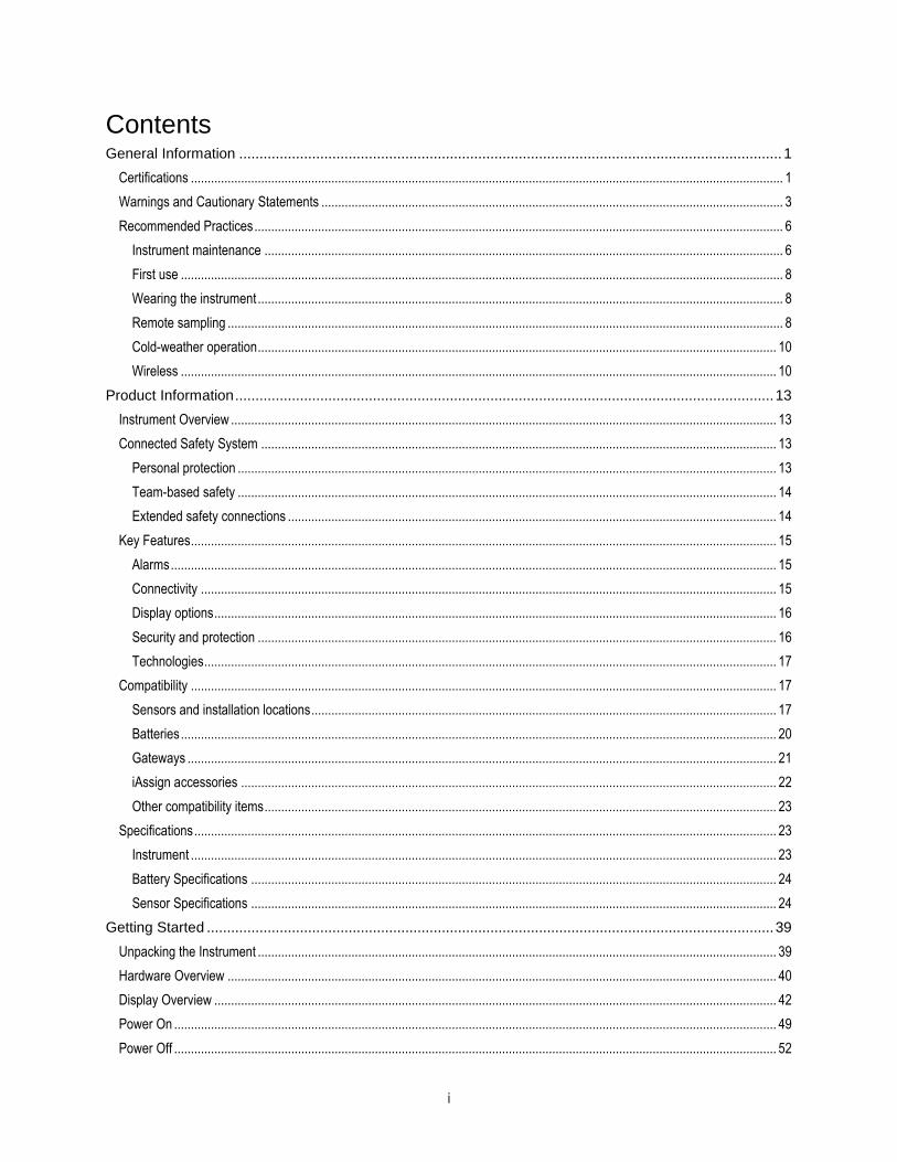
Contents General Information ...................................................................................................................................... 1
Certifications ................................................................................................................................................................................. 1
Warnings and Cautionary Statements .......................................................................................................................................... 3
Recommended Practices .............................................................................................................................................................. 6
Instrument maintenance ........................................................................................................................................................... 6
First use .................................................................................................................................................................................... 8
Wearing the instrument ............................................................................................................................................................. 8
Remote sampling ...................................................................................................................................................................... 8
Cold-weather operation ........................................................................................................................................................... 10
Wireless .................................................................................................................................................................................. 10
Product Information ..................................................................................................................................... 13
Instrument Overview ................................................................................................................................................................... 13
Connected Safety System .......................................................................................................................................................... 13
Personal protection ................................................................................................................................................................. 13
Team-based safety ................................................................................................................................................................. 14
Extended safety connections .................................................................................................................................................. 14
Key Features ............................................................................................................................................................................... 15
Alarms ..................................................................................................................................................................................... 15
Connectivity ............................................................................................................................................................................ 15
Display options ........................................................................................................................................................................ 16
Security and protection ........................................................................................................................................................... 16
Technologies ........................................................................................................................................................................... 17
Compatibility ............................................................................................................................................................................... 17
Sensors and installation locations ........................................................................................................................................... 17
Batteries .................................................................................................................................................................................. 20
Gateways ................................................................................................................................................................................ 21
iAssign accessories ................................................................................................................................................................ 22
Other compatibility items ......................................................................................................................................................... 23
Specifications .............................................................................................................................................................................. 23
Instrument ............................................................................................................................................................................... 23
Battery Specifications ............................................................................................................................................................. 24
Sensor Specifications ............................................................................................................................................................. 24
Getting Started ............................................................................................................................................ 39
Unpacking the Instrument ........................................................................................................................................................... 39
Hardware Overview .................................................................................................................................................................... 40
Display Overview ........................................................................................................................................................................ 42
Power On .................................................................................................................................................................................... 49
Power Off .................................................................................................................................................................................... 52

ii
Settings ....................................................................................................................................................... 53
Guidelines ................................................................................................................................................................................... 53
Accessing Settings ...................................................................................................................................................................... 53
Settings Menus ........................................................................................................................................................................... 54
Examples for Working in Settings ............................................................................................................................................... 54
Reviewing and Editing Settings .................................................................................................................................................. 56
Maintenance menu ................................................................................................................................................................. 57
Start-up menu ......................................................................................................................................................................... 60
Operation menu ...................................................................................................................................................................... 61
Alarm menu ............................................................................................................................................................................. 63
Sensor menu ........................................................................................................................................................................... 65
Admin menu ............................................................................................................................................................................ 67
Wireless menu ........................................................................................................................................................................ 69
Operation..................................................................................................................................................... 73
The Instrument Buttons ............................................................................................................................................................... 73
The Instrument Display ............................................................................................................................................................... 74
Operating the Instrument ............................................................................................................................................................ 75
Wearing the Instrument ............................................................................................................................................................... 78
Using Upgrade Cards ................................................................................................................................................................. 78
iAssign Data ................................................................................................................................................................................ 78
Using LENS Wireless .................................................................................................................................................................. 79
LENS instrument basics .......................................................................................................................................................... 79
Joining a LENS group ............................................................................................................................................................. 80
Leaving a LENS group ............................................................................................................................................................ 81
Peer gas readings ................................................................................................................................................................... 82
Live Monitoring ............................................................................................................................................................................ 82
RGX Gateway ......................................................................................................................................................................... 83
Smart-device gateway ............................................................................................................................................................ 83
Man-down Functionality .............................................................................................................................................................. 83
Alarms and Warnings At-a-glance .............................................................................................................................................. 83
Alarms ..................................................................................................................................................................................... 83
Warnings ................................................................................................................................................................................. 85
Alarms, Warnings, and Notifications ........................................................................................................... 87
Overview ..................................................................................................................................................................................... 87
Alarms ......................................................................................................................................................................................... 87
Warnings ..................................................................................................................................................................................... 91
Indicators .................................................................................................................................................................................... 94
Failures and Errors ..................................................................................................................................................................... 94
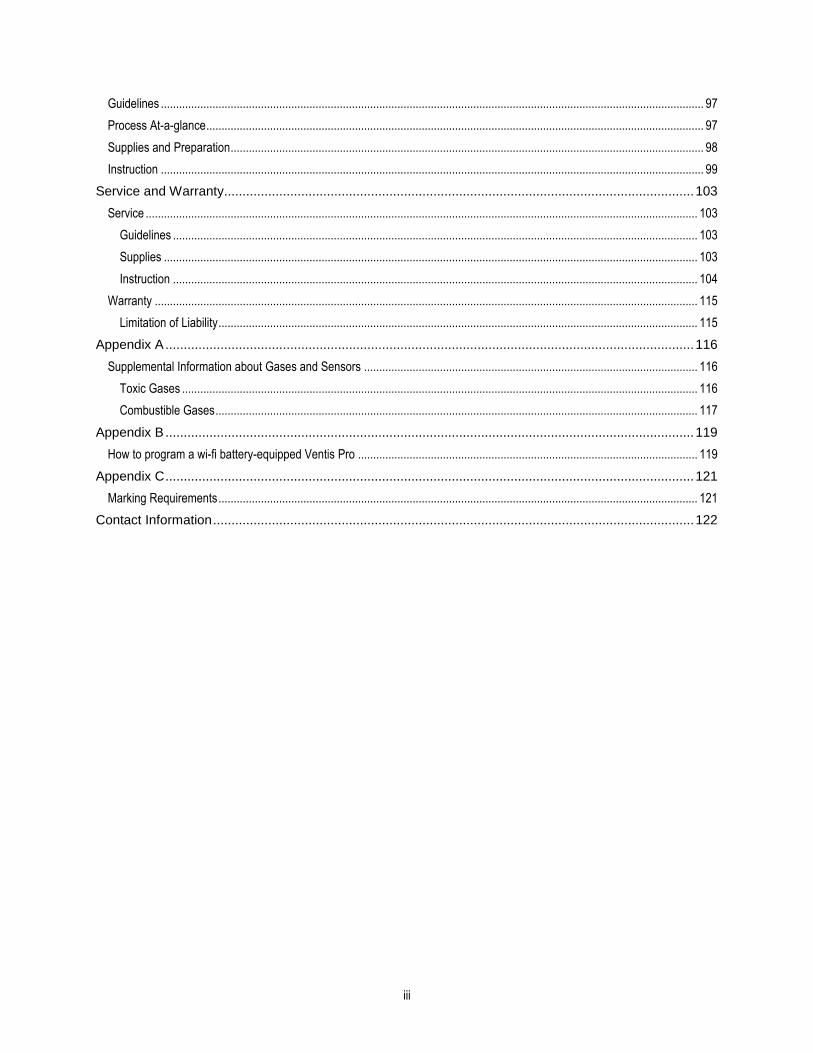
Maintenance ................................................................................................................................................ 97
iii
Guidelines ................................................................................................................................................................................... 97
Process At-a-glance .................................................................................................................................................................... 97
Supplies and Preparation ............................................................................................................................................................ 98
Instruction ................................................................................................................................................................................... 99
Service and Warranty ................................................................................................................................ 103
Service ...................................................................................................................................................................................... 103
Guidelines ............................................................................................................................................................................. 103
Supplies ................................................................................................................................................................................ 103
Instruction ............................................................................................................................................................................. 104
Warranty ................................................................................................................................................................................... 115
Limitation of Liability .............................................................................................................................................................. 115
Appendix A ................................................................................................................................................ 116
Supplemental Information about Gases and Sensors .............................................................................................................. 116
Toxic Gases .......................................................................................................................................................................... 116
Combustible Gases ............................................................................................................................................................... 117
Appendix B ................................................................................................................................................ 119
How to program a wi-fi battery-equipped Ventis Pro ................................................................................................................ 119
Appendix C ................................................................................................................................................ 121
Marking Requirements .............................................................................................................................................................. 121
Contact Information ................................................................................................................................... 122

iv
Tables and Figures Table 1.1 Hazardous-area certifications ........................................................................................................................................... 1
Table 1.2 Wireless certifications ....................................................................................................................................................... 3
Table 1.3 Warnings and cautionary statements ................................................................................................................................ 3
Table 1.4 Recommended frequencies for instrument maintenance ................................................................................................. 8
Table 1.5 Minimum sample time for common sample-line lengths .................................................................................................. 9
Table 1.6 Range guidelines for wireless connections ..................................................................................................................... 10
Figure 2.1 Industrial Scientific connected safety system ................................................................................................................ 14
Figure 2.2.A Sensor compatibility and installation locations for the Ventis Pro4 ............................................................................ 18
Figure 2.2.B Sensor compatibility and installation locations for the Ventis Pro5 ............................................................................ 19
Table 2.1 Sensor compatibility and installation locations................................................................................................................ 19
Table 2.2 Battery compatibility ........................................................................................................................................................ 21
Table 2.3 Ventis Pro–gateway firmware and settings requirements ............................................................................................... 22
Table 2.4. iAssign accessories compatibility ................................................................................................................................... 22
Table 2.5 Instrument and pump specifications ............................................................................................................................... 23
Table 2.6 Battery specifications ...................................................................................................................................................... 24
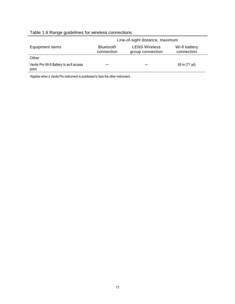
Table 2.7 Sensor specifications ...................................................................................................................................................... 25
Table 3.1 Package contents ........................................................................................................................................................... 39
Figure 3.1.A Hardware overview diffusion instrument .................................................................................................................... 40
Figure 3.1.B Hardware overview aspirated instrument ................................................................................................................... 41
Figure 3.2.A Reading the display during operation ......................................................................................................................... 44
Figure 3.2.B Reading the display during an event (warning or alarm) ............................................................................................ 45
Figure 3.2.C Reading the display during maintenance ................................................................................................................... 46
Figure 3.2.D Reading the display while working in settings ............................................................................................................ 47
Figure 3.3 Power on ........................................................................................................................................................................ 52
Figure 3.4 Power off ........................................................................................................................................................................ 52
Table 4.1 Settings menus ............................................................................................................................................................... 54
Figure 4.1.A Example for editing a single-item setting .................................................................................................................... 55
Figure 4.1.B Example for editing a multi-item setting ..................................................................................................................... 56
Figure 4.2.A Navigating and using maintenance options................................................................................................................ 59
Figure 4.2.B Navigating and editing start-up settings .................................................................................................................... 60
Figure 4.2.C Navigating and editing operation settings ................................................................................................................. 62
Figure 4.2.D Navigating and editing alarm settings ....................................................................................................................... 64
Figure 4.2.E Navigating and editing sensor settings...................................................................................................................... 66
Figure 4.2.F Navigating and editing admin settings ....................................................................................................................... 69
Figure 4.2.G Navigating and editing wireless settings .................................................................................................................... 72
Figure 5.1 Using the buttons during operation ................................................................................................................................ 74
Figure 5.2 Home ............................................................................................................................................................................. 75
Figure 5.3 Operation instruction ...................................................................................................................................................... 77
Figure 5.4 Using iAssign tags ......................................................................................................................................................... 79
Figure 5.5 LENS group peer-instrument locations .......................................................................................................................... 80

v
Figure 5.6 Join a LENS group via pairing ....................................................................................................................................... 81
Figure 5.7 Leave a LENS group ..................................................................................................................................................... 81
Figure 5.8 Access peer gas readings ............................................................................................................................................. 82
Table 5.1 Live-monitoring connection status .................................................................................................................................. 82
Table 6.1 Alarm events (list) ........................................................................................................................................................... 88
Figure 6.1 Alarm events (display screens) ...................................................................................................................................... 91
Table 6.2 Warnings (list) ................................................................................................................................................................. 92
Figure 6.2 Warnings (display screens) ........................................................................................................................................... 93
Table 6.3 Failures and errors .......................................................................................................................................................... 94
Table 6.4 Critical errors ................................................................................................................................................................... 95
Figure 7.1 Maintenance supplies and preparation .......................................................................................................................... 98
Table 7.1 Calibration failure: possible causes and recommendations .......................................................................................... 102
Figure 8.1 Instrument diagram ..................................................................................................................................................... 104
Figure 8.2 Pump module diagram ................................................................................................................................................. 105
Table 8.1 Instrument and pump module parts list ......................................................................................................................... 106
Figure 8.3 Service Tasks .............................................................................................................................................................. 114
Table A.1 Cross-sensitivity guidelines (%) ................................................................................................................................... 116
Table A.2 LEL correlation factors for the sensors 17155304-K, -L, and -M ................................................................................. 117
Table A.3 LEL correlation factorsa for the sensor 17155304-U ................................................................................................... 118


1 General Information
Certifications
Warnings and Cautionary Statements
Recommended Practices
Certifications Certifications for the Ventis® Pro4 Multi-Gas Monitor and Ventis® Pro5 Multi-Gas Monitor, at the time of this document's publication, are listed below in Tables 1.1 and 1.2. To determine the hazardous-area classifications for which an instrument is certified, refer to its label or the instrument order.
Table 1.1 Hazardous-area certifications
Certifying Body (CB)
Area Classifications Approved Temperature Range
ANZEx Ex ia I Ma / Ex ia IIC T4 Ga -40 °C to +50 °C (-40 °F to +122 °F)
Ex d ia I Mb / Ex d ia IIC T4 Gb with IR Sensor -20 °C to +50 °C (-4 °F to +122 °F)
ATEXa Equipment Group and Category II 1G, Ex ia IIC, equipment protection level Ga, Temperature Class T4
Equipment Group and Category II 2G, Ex d ia IIC, equipment protection level Gb, Temperature Class T4, with IR sensor
Equipment Group and Category I M1, Ex ia I, equipment protection level Ma, Temperature Class T4
Equipment Group and Category I M1, Ex d ia I, equipment protection level Ma, Temperature Class T4, with IR sensor
-40 °C to +50 °C (-40 °F to +122 °F)
CSAb Class I, Division 1, Groups A, B, C, and D, Temperature Class T4
Class I, Zone 1, Ex d ia IIC, Temperature Class T4
-40 °C to +50 °C (-40 °F to +122 °F)
C22.2 No. 152 applies to %LEL reading for the sensor Part Number 17155304-K only
-20 °C to +50 °C (-4 °F to +122 °F)
IECExa Class I, Zone 0, Ex ia IIC, equipment protection level Ga, Temperature Class T4
-40 °C to +50 °C (-40 °F to +122 °F)

2
Table 1.1 Hazardous-area certifications
Certifying Body (CB)
Area Classifications Approved Temperature Range
Class I, Zone 1, Ex d ia IIC, equipment protection level Gb, Temperature Class T4, with IR sensor
INMETRO Class I, Zone 0, Ex ia IIC, equipment protection level Ga, Temperature Class T4
Class I, Zone 1, Ex d ia IIC, equipment protection level Gb, Temperature Class T4, with IR sensor
-40 °C to +50 °C (-40 °F to +122 °F)
MSHAC Permissible for Underground Mines -40 °C to +50 °C
(-40 °F to +122 °F)
UL Class I, Division 1, Groups A, B, C, and D, Temperature Class T4
Class II, Division 1, Groups E, F, and G, Temperature Class T4
Class I, Zone 0, AEx ia IIC, Temperature Class T4
Class I, Zone 1, AEx d ia II C, Temperature Class T4, with IR sensor
-40 °C to +50 °C (-40 °F to +122 °F)
aMarking requirements are reproduced in Appendix B.
bThe following apply to instruments that are to be used in compliance with the CSA certification: Ventis Pro4 and Ventis Pro5 instruments are CSA certified according to the Canadian Electrical Code for use in Class I, Division 1 and Class I, Zone 1 Hazardous Locations within an ambient temperature range of Tamb: -40 °C to +50 °C.
• CSA has assessed only the %LEL combustible gas detection portion of this instrument (the sensor part number 17155304-K only) for
performance according to CSA Standard C22.2 No. 152. Within an ambient temperature range of Tamb: 0 °C to +50 °C, the accuracy is
±3%. Within an ambient temperature range of Tamb: -20°C up to 0°C, the accuracy is ±5%. This is applicable only when the monitor has
been calibrated to 50% LEL CH4.
CAUTION: CSA C22.2 No. 152 requires before each day’s usage, sensitivity must be tested on a known concentration of pentane or
methane equivalent to 25% or 50% of full scale concentration. Accuracy must be within -0% to +20% of actual concentration. Accuracy
may be corrected by referring to the zero and calibration section of the Product Manual.
ATTENTION: CSA C22.2 N°152 exige que la sensibilité de l’instrument soit testée avant l’utilisation quotidienne de l’instrument sur une
concentration connue de pentane ou de méthane équivalente à 25 % ou 50 % de la concentration totale. L'exactitude doit être entre -0 %
et +20 % de la concentration réelle. L’exactitude peut être corrigée en se référant à la partie concernant la mise à zéro et l’étalonnage
dans le Manuel du produit. CMSHA requires the monitor be calibrated according to the procedures in the Product Manual only. MSHA also requires the monitor display
methane in the percent-by-volume mode (0-5%) for compliance determinations required by 30 CFR Part 75, subpart D.
In addition to the certifications listed below, refer to the Industrial Scientific websites for the most up-to-date information about wireless product certifications.

3
Table 1.2 Wireless certifications
Agency or authority
Identification number or registration number
Country or region
ANRT MR 15824 ANRT 2018 Morocco
CNC C-20626 and C-20709 Argentina
FCC PHH-BLEPAN1740, U90-SM200, PHH-VPX USA
IC 216Q-1740, 7084A-SM200, 20727-VPX Canada
NCC CCAJ18LP0C30T2 and CCAJ18LP0C31T2 Taiwan
NTC sn 549 and sn 550 Thailand
TRCa TRC/LPD/2018/159 Jordan
aVentis Pro 5 only
Warnings and Cautionary Statements
Read and understand this Product Manual before operating or servicing the instrument. Failure to perform certain procedures or note certain conditions—provided below and throughout the manual—may impair the performance of the product, cause unsafe conditions, or both.
Table 1.3 Warnings and cautionary statements
If it appears that the instrument is not working correctly, immediately contact Industrial Scientific.
Only qualified personnel should operate, maintain, and service the instrument.
Substitution of components may impair intrinsic safety, which may cause an unsafe condition.
Substituer des composants peut compromettre la sécurité intrinsèque, ce qui peut résulter en une situation dangereuse.
Do not use in oxygen-enriched atmospheres. If the atmosphere becomes oxygen enriched, it may cause inaccurate readings.
Oxygen-deficient atmospheres may cause inaccurate readings.
A rapid increase in a gas reading that is followed by a declining or erratic reading may indicate an over-range condition, which may be hazardous.
Sudden changes in atmospheric pressure may cause temporary fluctuations in gas readings.
Temperatures below -20 °C (-4 °F) are likely to cause decreased functionality in the instrument's display screen and man-down feature.
Sudden changes in ambient-air temperature will cause a form of sensor drift in the Carbon Monoxide/Hydrogen Sulfide (CO/H2S) sensor (part number 17155306-J) that will produce temporary variations in the sensor's readings:

4
Table 1.3 Warnings and cautionary statements
• If the temperature suddenly increases, the CO reading will temporarily decrease and the H2S reading may temporarily increase.
• If the temperature suddenly decreases, the CO reading will temporarily increase and the H2S reading may temporarily decrease.
The readings will stabilize when the sensor has acclimated to the change in temperature. For example, if the ambient-air temperatures changes from a "room temperature" of 20 °C (68 °F) to an outdoor temperature of 0 °C (32 °F), the stabilization time is approximately 15 minutes; with smaller or larger changes in temperature, stabilization time will be shorter or longer, respectively.
Note: If the sensor is to be zeroed after a sudden change in ambient-air temperature, allow the sensor and its readings to stabilize before zeroing.
The Long-life O2 sensors (part number 17155304-Y and 17155306-Y) are biased sensor, requiring continuous power to operate to specification. Continuous power is provided by a charged battery, regardless if the instrument is powered on. If no power is provided to the sensor, it will experience sensor drift and generate erroneous readings.
If an instrument containing a biased sensor experiences a state of no charge, sensor drift will likely occur. If so, Industrial Scientific recommends that the instrument be installed on a compatible charger or docking station. If installed on a docking station, the instrument may fail calibration, but can remain docked to charge. After charging*, undock the instrument; then, redock the instrument or zero it manually. If the instrument does not pass zero, repeat the zero.
*If the sensor has been in a no-power state for seven days, it may require a charge period of up to three hours. Charge time will vary based on how long the sensor has been in a no-power state.
Do not use the Ventis Slide-on Pump (VSP) when sampling for these target gases: Chlorine (CL2), Chlorine Dioxide (CLO2), Hydrogen Chloride (HCL), and volatile organic compounds (VOC), or when a sensor for any of these gases is installed and the target gas is unknown; use only the Ventis Pro Pump Module. The use of the VSP with these gases will result in inaccurate gas readings due to their susceptibility to absorption.
To avoid potentially inaccurate readings for some applications—monitoring for gases other than O2, CO, CO2, H2S, and combustible gases [LEL/CH4]—only use a leather case as a carrying case. Do not power on, operate, or power off the instrument while it is in a leather case.
Silicone and other known contaminants may damage the instrument’s combustible gas sensors, which can cause inaccurate gas readings.
To support accurate readings, keep clean and unobstructed all filters, sensor ports, water barriers, and pump inlet.
Obstruction of sensor openings—due to dust, dirt, water, or another cause—can inhibit the unit’s ability to measure gas concentrations accurately. To support accurate readings, keep sensor openings clean, dry, and properly exposed to the ambient air.
Obstructed, contaminated, or damaged sensor water barriers (or their gaskets) can inhibit the unit’s ability to measure gas concentrations accurately. To support accurate readings, replace the sensor water barriers and gaskets as needed (see “Service” for instructions).
WARNING – When attached, the Alarm Silencer accessory suspends gas detection and man-down alarms. The instrument will NOT alert the user to hazards associated with these alarms when this accessory is in use.
WARNING – Explosion hazard. Only replace batteries in nonhazardous locations.
Charge the instrument’s battery only in nonhazardous locations. Chargez la batterie de l’instrument uniquement dans des lieux sans danger.

5
Table 1.3 Warnings and cautionary statements
Charge the instrument's battery using only compatible accessories from Industrial Scientific, including the chargers listed below.
Part Number Description
18108191 Ventis Single-Unit Charger
18108209 Ventis Single-Unit Charger/Datalink
18108651 Ventis Single-Unit Automotive Charger,12VDC
18108652 Ventis Single-Unit Truck-Mount Charger, 12VDC, with Cigarette Adapter
18108653 Ventis Single-Unit Truck-Mount Charger, 12VDC, Hard Wired
Perform all instrument service tasks and maintenance procedures in nonhazardous locations only. This includes the removal, replacement, or adjustment of any part on or inside the instrument or its pump.
Exécutez toutes les procédures de service les tâches de service sur l’instrument uniquement dans des lieux sans danger. Ceci comprend la dépose d’une pièce positionnée sur l’instrument ou à l’intérieur de celui-ci, ou bien la rechange ou le réglage d’une telle pièce.
Battery contacts are exposed on batteries when they are removed from the instrument. Do not touch the battery contacts and do not stack batteries on top of each other.
Do not use solvents or cleaning solutions on the instrument or its components.
The radios in the Industrial Scientific Ventis Pro 4 and Ventis Pro 5 Portable Multi Gas monitors have been assessed to and found to be below limits as defined in FCC; Innovation, Science and Economic Development Canada; and European Council recommendation 1995/519/EC requirements for human exposure to electromagnetic fields.
This equipment has been tested and found to comply with the limits for a Class B digital device, pursuant to part 15 of the FCC Rules. These limits are designed to provide reasonable protection against harmful interference in a residential installation. This equipment generates, uses and can radiate radio frequency energy and, if not installed and used in accordance with the instructions, may cause harmful interference to radio communications. However, there is no guarantee that interference will not occur in a particular installation. If this equipment does cause harmful interference to radio or television reception, which can be determined by turning the equipment off and on, the user is encouraged to try to correct the interference by one or more of the following measures:
• Reorient or relocate the receiving antenna.
• Increase the separation between the equipment and receiver.
• Connect the equipment into an outlet on a circuit different from that to which the receiver is connected.
• Consult the dealer or an experienced radio/TV technician for help.
Changes or modification made that are not expressly approved by the manufacturer could void the user’s authority to operate the equipment.
This device complies with Industry Canada license-exempt RSS standard(s). Operation is subject to the following two conditions: (1) this device may not cause interference, and (2) this device must accept any interference, including interference that may cause undesired operation of the device.
Le présent appareil est conforme aux CNR d'Industrie Canada applicables aux appareils radio exempts de licence. L'exploitation est autorisée aux deux conditions suivantes : (1) l'appareil ne doit pas produire de brouillage, et (2) l'utilisateur de l'appareil doit accepter tout brouillage radioélectrique subi, même si le brouillage est susceptible d'en compromettre le fonctionnement.
This equipment may not cause interference with duly authorized systems and is not entitled to protection from harmful interference.

6
Table 1.3 Warnings and cautionary statements
The Ventis Pro 4 and Ventis Pro 5 Portable Multi Gas Monitors contain radio communication modules that generate radio frequency energy. They frequencies and output powers are listed below:
Maximum Transmit Power
NFC 13.56 MHz -43.2 dBm (0.000048 mW)
Bluetooth Low Energy 2402 to 2480 MHz 0 dBm (1 mW)
LENS Wireless 2405 to 2480 MHz 3 dBm (2 mW)
Wi-fi (if equipped) 2412 to 2472 MHz 19.1 dBi (81.3 mW) at low Tx duty cycle
Industrial Scientific recommends persons with a pacemaker or implantable cardio defibrillator (ICD) should maintain a minimum separation distance of 15 cm (6 ") between the pacemaker or ICD and a wireless-enabled instrument. Please consult your physician or pacemaker or ICD manufacturer for additional guidance and recommendations.
MSHA Conditions of Safe Use
The diffusion versions of the Ventis Pro 4 and Pro 5 are approved for use with either the rechargeable P/N 17134453-X2, or P/N 17148313-2 (extended) 3.7 volt, lithium-ion batteries only.
The batteries are not user-replaceable.
The aspirated version of the Ventis Pro 4 and Pro 5 is approved for use with the P/N 17148313-2 extended battery only.
To be charged on the surface or underground in accordance with 30 CFR 75.340 (the applicable regulations pertaining to battery-charging stations) and MSHA Program Information Bulletin PIB P11-12.
Charge monitors with an Industrial Scientific Corporation charger designed for use with this monitor.
Calibrate according to the procedures in the Product Manual, Document No. 17156830-1.
The monitor must display methane in the percent-by-volume mode (0-5%) for compliance determinations required by 30 CFR Part 75, Subpart D.
The respective minimum distances that shall be maintained between the Ventis Pro 4 or Pro 5 monitors and any blasting circuits, explosives and detonators for MSHA and the PA Department of Environmental Protection are:
MSHA - 6 inches (15.2 cm)
PA DEP - 30 inches (76 cm)
Recommended Practices
Instrument maintenance
The procedures defined below help to maintain instrument functionality and support operator safety.
Industrial Scientific minimum-frequency recommendations for these procedures are summarized below in Table 1.4. These recommendations are provided to help support worker safety and are based on field data, safe work procedures, industry best practices, and regulatory standards. Industrial Scientific is not responsible for determining a company’s safety practices or establishing its safety policies, which may be
7
affected by the directives and recommendations of regulatory groups, environmental conditions, operating conditions, instrument use patterns and exposure to gas, and other factors.
Settings
Settings control how an instrument will perform. They are used to help ensure the instrument is in compliance with company safety policy and applicable regulations, laws, and guidelines as issued by regulatory agencies and government or industry groups.
Utilities
Maintenance procedures are known as "utilities". Utilities are primarily used to test the instrument or its components for functionality or performance. Each utility is defined below.
Self-test
The self-test is used to test the functionality of the instrument’s memory operations, battery, display screen, and each alarm signal type (audible, visual, and vibration).
Bump Test (or "functional test")
Bump testing is a functional test in which an instrument's installed sensors are to be briefly exposed to (or “bumped” by) calibration gases in concentrations that are greater than the sensors’ low-alarm setpoints. This will cause the instrument to go into low alarm and will indicate which sensors pass or fail this basic test for response to gas.
Zero
Zeroing adjusts the sensors’ “baseline” readings, which become the points of comparison for subsequent gas readings. It is a prerequisite for calibration. During zeroing, the installed sensors are to be exposed to an air sample from a zero-grade-air cylinder or ambient air that is known to be clean air. If there are gases in the air sample that are below the lowest alarm level, the instrument will read them as zero; its task is to read the air sample as clean air. The user's task is to ensure the air is clean.
Calibration
Regular calibrations promote the accurate measurement of gas concentration values. During calibration, an instrument’s installed sensors are to be exposed to their set concentrations of calibration gases. Based on the sensors’ responses, the instrument will self-adjust to compensate for declining sensor sensitivity, which naturally occurs as the installed sensors are used or “consumed”.
Note: During calibration, the span reserve percentage value for each sensor is displayed. An indicator of a sensor's remaining life, when the value is less than 50%, the sensor will no longer pass calibration
Docking
When docked, instruments that are supported by iNet® Control or DSSAC (Docking Station Software Admin Console) will be maintained for all scheduled bump tests and calibrations, synchronized for any changes to settings, and upgraded for improvements from Industrial Scientific.
Other Maintenance
The time-weighted average (TWA), short-term exposure limit (STEL), and peak readings can each be "cleared". When any summary reading is cleared, its value is reset to zero and its time-related setting is also reset to zero.

8
Table 1.4 Recommended frequencies for instrument maintenance
Procedure Recommended minimum frequency
Settings Before first use, when an installed sensor is replaced, and as needed.
Calibrationa Before first use and monthly thereafter.
Bump testb Before first use and prior to each day’s use thereafter.
Self-testc As needed.
aBetween regular calibration procedures, Industrial Scientific also recommends that calibration be performed immediately following each of these incidences: the unit falls, is dropped, or experiences another significant impact; is exposed to water; fails a bump test; or has been exposed to an over-range (positive or negative) gas concentration. Calibration is also recommended after the installation of a new (or replacement) sensor.
bIf conditions do not permit daily bump testing, the procedure may be done less frequently based on instrument use, potential exposure to gas, and environmental conditions as determined by company policy and local regulatory standards.
bWhen redundant sensors are operating on DualSense® technology, bump testing these sensors may be done less frequently based on company safety policy.
cThe instrument performs a self-test during power on. For an instrument that is set for always-on, the instrument will automatically perform a self-test every 24 hours. The self-test can also be completed on demand by the instrument user.
Note: The use of calibration gases not provided by Industrial Scientific may void product warranties and limit potential liability claims.
First use
To prepare the Ventis Pro Series instrument for first use, qualified personnel should ensure the following are completed:
• Charge the battery at an ambient temperature of less than 40 °C (104 °F).
• Review instrument settings and adjust them as needed.
• Calibrate the instrument.
• Complete a bump test.
Wearing the instrument
Based on the U.S. Department of Labor's Occupational Safety and Health Administration (OSHA) definition of the breathing zone, it is recommended that the instrument be worn within a 25.4 cm (10") radius of the nose and mouth. Refer to OSHA and to other agencies or groups as needed for additional information.
Remote sampling
WARNING: Do not use the Ventis Slide-on Pump (VSP) when sampling for these target gases: Chlorine (CL2), Chlorine Dioxide (CLO2), Hydrogen Chloride (HCL), and volatile organic compounds (VOC), or when a sensor for any of these gases is installed and the target gas is unknown; use only the Ventis Pro Pump Module. The use of the VSP with these gases will result in inaccurate gas readings due to their susceptibility to absorption.
When sampling with a motorized pump and sampling line, Industrial Scientific recommends the following:
• Never operate a pump without an internal filter installed.
• Choose the tubing type based on the target gases. If the target gases are known, use Teflon-lined tubing when sampling for these gases: chlorine (Cl2), chlorine dioxide (ClO2), hydrogen chloride (HCl), and volatile organic compounds (VOCs). For other known target gases, urethane tubing or Teflon-lined tubing may be used. When the target gases are unknown, use Teflon-lined tubing.

9
• Know the length of the sample line as it is a factor in determining sampling time. Sample-line length is defined as the distance from the dust filter–water stop opening to the point where the line connects to the pump's inlet. Ensure sample-line length does not exceed the pump's maximum draw.
• A sample line may consist of tubing, a probe, or a probe and tubing.
• Use a dust filter-water stop (external filter) on the sample line, installed at the line's end, in addition to the internal filter within the pump inlet barrel.
• When replacing pump filters*:
o Replace external and internal filters at the same time.
o Power-off the instrument prior to changing the filters.
o Inspect the pump inlet cap and barrel; remove any dirt, debris, or liquid by blowing air through the cap or wiping gently with a clean, lint-free cloth.
*See also -
Pump cap and internal filter replacement.
Dust filter-water stop
• Before and after each air sample, perform a test of the full sampling line.
o Use your thumb to block the end of the sampling line at the water-stop opening. This should cause a pump-fault alarm.
o Unblock the water-stop opening. After the alarm cycle completes, the pump should resume normal operation.
Note: If a pump fault does not occur, check and correct for cracks or other damage, debris, and proper installation in these areas: the sampling line and its connections, the pump's inlet cap and inlet barrel, and the dust filter-water stop items at the end of the sampling line and inside the pump inlet barrel.
• Based on sample-line length, calculate the minimum time recommended for the air sample to reach the instrument's sensors. As shown below, use a base time of 2 minutes, and add 2 seconds for each 30 cm (1 ') of line length. Watch the display screen for gas readings and, if present, allow them to stabilize to determine the reading.
Table 1.5 Minimum sample time for common sample-line lengths
Sample-line length Base time
(minutes)
+ Sample-line-length
factor
= Minimum sample time
(mm:ss)
3.05 m (10 ') 2 min + (10 ' x 2 s) = 02:20
6.10 m (20 ') 2 min + (20 ' x 2 s) = 02:40
9.14 m (30 ') 2 min + (30 ' x 2 s) = 03:00
12.10 m (40 ') 2 min + (40 ' x 2 s) = 03:20
15.24 m (50 ') 2 min + (50 ' x 2 s) = 03:40
18.29 m (60 ') 2 min + (60 ' x 2 s) = 04:00
21.34 m (70 ') 2 min + (70 ' x 2 s) = 04:20
24.38 m (80 ') 2 min + (80 ' x 2 s) = 04:40
27.43 m (90 ') 2 min + (90 ' x 2 s) = 05:00
30.48 m (100 ') 2 min + (100 ' x 2 s) = 05:20

10
Cold-weather operation
Use caution when operating the instrument in temperatures below -20 °C (-4 °F), which can diminish display-screen legibility and man-down functionality. To help support functionality and available battery power, the following practices are recommended.
• Do not operate the instrument in temperatures that are not within the temperature ranges of the installed sensors (see "Table 2.7, Sensor specifications").
• Use a compatible, fully charged extended range battery.
• Before using the instrument in the cold-weather environment, power it on in a warm-up environment (approximately 20 °C [68 °F]).
• Alternately operate the instrument in the cold-weather and warm-up environments.
• Do not operate the instrument unmanned.
Wireless
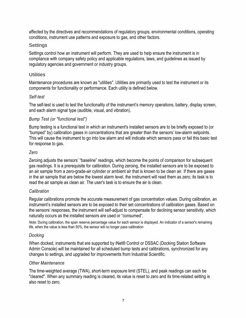
Ventis Pro instruments and installed Ventis Pro Wi-fi Batteries can have wireless operations enabled for a variety of features and functions. During instrument operation, unintended interference can weaken wireless signals. These in-field practices can sometimes enhance signal strength.
• Adjust your position relative to nearby buildings or their walls, floors, and ceilings, and other structures such as a vehicle or machinery.
• GPS is supported by outdoor, open-sky positioning.
Ventis Pro instruments are equipped with a radio that is used in the wireless connection of equipment items, within a LENS™ Wireless group, which permits the sharing of data (e.g., alarms) among instruments. LENS also supports the exchange of instrument data with iNet®, via a compatible gateway, such as the RGX™ Gateway, to support iNet Now live-monitoring features*. The Ventis Pro Wi-fi Battery supports live monitoring of the instrument to which it is installed, transmitting instrument alarms and other data to iNet. Use the range guidelines supplied below to maintain each connection type.
Note: The intended wireless performance is supported through docking station operations, which provide regular instrument and wi-fi battery firmware updates along with maintenance tasks.
*Available when the iNet Now service and all instruments to be monitored have been activated for live monitoring.
Table 1.6 Range guidelines for wireless connections
Line-of-sight distance, maximum
Equipment items Bluetooth connection
LENS Wireless group connection
Wi-fi battery connection
Instrument to instrument
Ventis Pro to Ventis Pro ─ 100 m (109 yd)a ─
Ventis Pro to Radius® BZ1 ─ 100 m (109 yd)a ─
Instrument to gateway
Ventis Pro to RGX Gateway ─ 100 m (109 yd) ─
Ventis Pro to smart-device gateway 30 m (32 yd) ─ ─
11
Table 1.6 Range guidelines for wireless connections
Line-of-sight distance, maximum
Equipment items Bluetooth connection
LENS Wireless group connection
Wi-fi battery connection
Other
Ventis Pro Wi-fi Battery to wi-fi access point
─ ─ 65 m (71 yd)
aApplies when a Ventis Pro instrument is positioned to face the other instrument.


2 Product Information
Instrument Overview
Connected Safety System
Key Features
Compatibility
Specifications
Instrument Overview
Ventis® Pro portable gas monitors provide personal protection to workers by monitoring for oxygen and a variety of toxic gases and combustible gases. The Ventis Pro5 can monitor up to five gases and has 23 compatible sensors, 14 of which are also compatible with the Ventis Pro4.
The instrument takes gas readings every second and records readings-related data every ten seconds. Data are stored in the instrument data log, which has these characteristics:
• Capacity for approximately three months of readings for a unit that is on 10 hours a day and has four installed, operational sensors.
• Data storage for up to 60 alarms, 30 error events, and 250 manual calibrations and bump tests.
• You can download the log using compatible accessories that are supported by iNet® Control, DSSAC, or Accessory Software from Industrial Scientific.
Ventis Pro Series instruments use a multisensory alarm-warning-indicator system comprising audible, visual, and vibration signals.
The instrument's display-screen language can be set to one of several available language options.
Connected Safety System
Personal protection
The Ventis Pro can operate as a gas-detection instrument for the personal protection of individual workers. To achieve this goal the instrument:
• Alerts the worker to actual and potential gas hazards.
• Activates a man-down alarm when it senses it is no longer being operated by its user.
• Includes a panic button.
• Optionally provides instructional messages for a variety of specific hazards.

14
Team-based safety
As part of a LENS (Linked Equipment Network for Safety) Wireless group, the Ventis Pro can also operate as a “peer” equipment item. Peer instruments share with one another gas readings, alarms, and other instrument events. This sharing allows workers and their supervisors to learn of nearby hazardous conditions and team members who may be in distress.
Extended safety connections
Beyond the individual worker and in-field, team-based safety, live monitoring of instruments via iNet Now provides remote visibility to in-field conditions and potentially hazardous events. Compatible gateways, such as the RGX, and instruments with enabled wireless batteries can communicate event information to iNet. These features enhance the safety team's preparedness for hazardous and unforeseen events and facilitate cooperation among first responders within your company and from local authorities.
As depicted below, the Industrial Scientific connected safety, live-monitoring system enhances the safety team's quick responses and preparedness for hazardous events.
Compatible gateway
iNet
Instrument data RGX Gateway iNet Now users (live monitoring
and subscription-based alerts)
Compatible wireless battery
Instrument
data
Figure 2.1 Industrial Scientific connected safety system

15
Key Features
Alarms
Gas and other alarms
The instrument will alert the user to the following types of alarm events: gas present, STEL, TWA, man-down, panic, and restricted area proximity using three different signal options and up to four distinct audio patterns. These alarms help ensure worker and team-based safety.
Gas alert
This optional feature notifies the instrument operator of the presence of gas in concentrations that may be approaching the instrument’s alarm setpoints. This alert can prompt workers to check the display screen for gas readings or an instructional message for a specific gas.
Latch alarm
This feature keeps an alarm on after the alarm-causing condition no longer exists. This sustains alarm signals, which encourages the worker to check the display screen for gas readings or an instructional message.
Man-down
The man-down feature allows the instrument to sense when it has not moved for a set interval. A man-down alarm may indicate the worker is unable to move or press the panic button, or that the instrument has become separated from its operator.
Panic button
Pressing the panic button turns on the instrument’s high-level alarm. This panic alarm can signal LENS teammates and others who are nearby that the worker or someone else is in distress, or that there is some concern about in-field circumstances.
Unique alarm action messages
A unique message (e.g., "EVACUATE") can be set for each installed sensor for these events: gas present (alert, low alarm, and high alarm), STEL, and TWA. You can also set a nonalarm, general message that displays during start-up.
Note: Some messages require iNet, DSSAC (Docking Station Software Admin Console), or Accessory Software.
Connectivity
Communications
Powerful communications features complement the gas detection capabilities of Industrial Scientific instruments:
• Communications among peer instruments via LENS wireless.
• Relay of instrument events to iNet via gateways and wireless-enabled instruments.
• iNet Now live monitoring and alerts keep the safety team and others informed about gas-detection and worker events.

16
iNet Now
A cloud-based app that monitors instrument events transmitted to iNet from gateways and instruments with enabled wireless batteries. iNet Now users can view a map that shows when workers are in trouble. With live monitoring, safety teams can follow, and as needed, react to these events. iNet Now alerts provide an additional connected safety channel.
LENS Wireless
LENS Wireless from Industrial Scientific allows gas-detection instruments and other peer equipment items to communicate with one another and form LENS groups. LENS peers can connect to named or ad hoc LENS groups by scanning for nearby groups and joining automatically, via pairing, or via assignment to a named LENS group.
Note: LENS group connection methods are mutually exclusive, enabling one disables all others.
Wireless batteries and GPS
When installed, the Ventis Pro Wi-fi Battery battery can transmit the instrument’s GPS position along with alarm events and some instrument updates to iNet, but not LENS group peer data.
Display options
Full screen alarms
This optional setting displays easy-to-read alarm details in large type.
Gas-information displays
These optional displays provide the worker with setpoints for gas events and calibration gas concentrations. This information can be set to display during start-up, operation, both, or neither.
Quick-status
This feature allows users to view specific information when the instrument is powered-off: installed sensors, available battery power, and instrument serial number.
Security and protection
Always-on
When enabled with a security code, this option prevents the instrument from being powered off during operation.
Damage resistance
These hardware features help protect the instrument and reduce damage to it:
• Raised ridges shield the sensor ports from dirt and damage when an instrument falls or is dropped.
• The display screen is recessed to protect it from scratches and other damage.
• Rails help reduce wear when the instrument is docked.

17
Technologies
DualSense Technology
DualSense® Technology uses two installed, paired sensors of the same type. The instrument processes both sensors’ data but displays only a single gas reading. Data are logged for each paired sensor and the derived DualSense "virtual" one. Each sensor operates independently and will operate as a single sensor if its redundant mate fails. This technology reduces the chance of instrument failure due to sensor failure.
iAssign
iAssign® Tags can write and iAssign Beacons can broadcast data to Ventis Pro instruments. You can program a tag with identifiers connected to a user and then write those identifiers to an instrument. Those identifiers become associated with the instrument’s gas readings, alarms, and other events.
Use iAssign Tags to:
• Tag instruments with user, site, and access level identifiers.
• Update a wi-fi battery’s network credentials for instruments so equipped.
Use iAssign Beacons to:
• Update an instrument’s site assignment.
• Keep users away from restricted areas with instrument proximity alarms.
• Temporarily disable functions such as man-down.
Compatibility
Sensors and installation locations
Each instrument’s compatible sensors can be installed in one or more specific locations as depicted in Figures 2.2.A and 2.2.B for Ventis Pro4 and Ventis Pro5, respectively. Table 2.1 provides the same information but in list format. In addition to the location restrictions for each sensor, these installation restrictions also apply:
Only install one infrared sensor.
If an infrared sensor is installed in location 1, do not install any of these sensors in location 2:
• Hydrogen Sulfide H2S (17155304-2)
• Oxygen, O2 (17155304-3)
• Oxygen, Long-life O2 (17155304-Y)
Do not install the Carbon Monoxide/Hydrogen Sulfide, CO/H2S, sensor (17155304-J) when any of these sensors is installed.
• Carbon Dioxide/LEL (Propane) IR (CO2/LEL) (17155304-U)
• Carbon Dioxide/Methane CO2/CH4 (17155304-V)
• Methane IR, CH4 (17155304-N)
For more information about each sensor, including its technology (e.g., infrared), see Table 2.7 Sensor Specifications.

18
Locations 1 or 2
Carbon Dioxide (CO2); 17155304-Q
Hydrogen Sulfide (H2S); 17155304-2
Oxygen (O2); 17155304-3a
Oxygen, Long-life (O2); 17155304-Ya and b
Location 2 only
Hydrocarbon IR (Propane); 17155304-P
LEL (Pentane); 17155304-K
LEL (Methane); 17155304-L
Methane, 0-5% vol; 17155304-M
Locations 3 or 4
Carbon Monoxide (CO); 17155306-1 a
Carbon Monoxide with low Hydrogen cross-sensitivity (CO/H2 Low); 17155306-G
Hydrogen Cyanide (HCN); 17155306-B
Hydrogen Sulfide (H2S); 17155306-2a
Nitrogen Dioxide (NO2); 17155306-4
Oxygen, Long-life (O2); 17155306-Yb
Sulfur Dioxide (SO2); 17155306-5 a
Figure 2.2.A Sensor compatibility and installation locations for the Ventis Pro4
aDualSense capable.
bBiased sensor.

19
Locations 1 or 2
Carbon Dioxide (CO2); 17155304-Q
Carbon Monoxide/Hydrogen Sulfide (CO/H2S); 17155304-J
Hydrogen Sulfide (H2S); 17155304-2
Oxygen (O2); 17155304-3a
Oxygen, Long-life (O2); 17155304-Y a and b*
Location 2 only
Carbon Dioxide/LEL (Propane), IR (CO2/LEL); 17155304-U
Carbon Dioxide/Methane (CO2/CH4); 17155304-V
Hydrocarbon IR (Propane); 17155304-P
LEL (Pentane); 17155304-K
LEL (Methane); 17155304-L
Methane, 0-5% vol; 17155304-M
Methane IR, (CH4); 17155304-N
Locations 3 or 4
Ammonia (NH3); 17155306-6
Carbon Monoxide (CO); 17155306-1a
Carbon Monoxide/Hydrogen Sulfide (CO/H2S); 17155306-Ja
Carbon Monoxide with low Hydrogen cross-sensitivity (CO/H2 Low); 17155306-G
Chlorine (Cl2); 17155306-7c
Hydrogen Cyanide (HCN); 17155306-B
Hydrogen Sulfide (H2S); 17155306-2a
Nitrogen Dioxide (NO2); 17155306-4
Oxygen, Long-life (O2); 17155306-Yb
Phosphine (PH3); 17155306-9
Sulfur Dioxide (SO2); 17155306-5a
Figure 2.2.B Sensor compatibility and installation locations for the Ventis Pro5
aDualSense capable.
bBiased sensor.
c WARNING: Do not use the Ventis Slide-on Pump (VSP) when sampling for these target gases: Chlorine (CL2), Chlorine Dioxide (CLO2), Hydrogen Chloride (HCL), and volatile organic compounds (VOC), or when a sensor for any of these gases is installed and the target gas is unknown; use only the Ventis Pro Pump Module. The use of the VSP with these gases will result in inaccurate gas readings due to their susceptibility to absorption.
Table 2.1 Sensor compatibility and installation locations
Ventis Pro4
Ventis Pro5
Installation locations
Part number
Sensor
Ammonia (NH3) No Yes 3 or 4 17155306-6
Carbon Dioxide (CO2) Yes Yes 1 or 2 17155304-Q
Carbon Dioxide/LEL (Propane), IR (CO2/LEL)
No Yes 2 17155304-U
Carbon Dioxide/Methane (CO2/CH4) No Yes 2 17155304-V

20
Table 2.1 Sensor compatibility and installation locations
Ventis Pro4
Ventis Pro5
Installation locations
Part number
Carbon Monoxide (CO)a Yes Yes 3 or 4 17155306-1
Carbon Monoxide/Hydrogen Sulfide (CO/H2S)
No Yes 1 or 2 17155304-J
Carbon Monoxide/Hydrogen Sulfide (CO/H2S)a
No Yes 3 or 4 17155306-J
Carbon Monoxide with low Hydrogen cross-sensitivity (CO/H2 Low)
Yes Yes 3 or 4 17155306-G
Chlorine (Cl2)c No Yes 3 or 4 17155306-7
Hydrocarbon IR (Propane) Yes Yes 2 17155304-P
Hydrogen Cyanide (HCN) Yes Yes 3 or 4 17155306-B
Hydrogen Sulfide (H2S) Yes Yes 1 or 2 17155304-2
Hydrogen Sulfide (H2S) a Yes Yes 3 or 4 17155306-2
LEL (Methane) Yes Yes 2 17155304-L
LEL (Pentane) Yes Yes 2 17155304-K
Methane, IR, (CH4) No Yes 2 17155304-N
Methane, 0-5% vol Yes Yes 2 17155304-M
Nitrogen Dioxide (NO2) Yes Yes 3 or 4 17155306-4
Oxygen (O2) a Yes Yes 1 or 2 17155304-3
Oxygen, Long-life (O2)a and b Yes Yes 1 or 2 17155304-Y
Oxygen, Long-life (O2)b Yes Yes 3 or 4 17155306-Y
Phosphine (PH3) No Yes 3 or 4 17155306-9
Sulfur Dioxide (SO2)a Yes Yes 3 or 4 17155306-5
aDualSense capable.
bBiased sensor.
c WARNING: Do not use the Ventis Slide-on Pump (VSP) when sampling for these target gases: Chlorine (CL2), Chlorine Dioxide (CLO2), Hydrogen Chloride (HCL), and volatile organic compounds (VOC), or when a sensor for any of these gases is installed and the target gas is unknown; use only the Ventis Pro Pump Module. The use of the VSP with these gases will result in inaccurate gas readings due to their susceptibility to absorption.
Batteries
The diffusion instrument is compatible with several rechargeable lithium-ion batteries, including a wi-fi equipped battery. The aspirated instrument is compatible only with the extended run-time battery. As indicated below, the label on each battery includes a controlled part number; corresponding orderable part numbers are supplied in Table 8.2, Battery parts list.

21
Table 2.2 Battery compatibility
Ventis Pro Series
Diffusion Aspirated
Rechargeable Lithium-ion batteries (part number*)
Ventis Pro Wi-fi Battery (17159022-XY*) Yes No
Ventis Standard Battery (17134453-XY*) Yes No
Ventis Slim Extended Battery (17157350-XY*) Yes No
Ventis Extended Run-time Battery (17148313-Y*) Yes Yes
*X indicates color and Y indicates approvals. For more information, see Table 8.2, Battery parts list.
For workers whose instruments will be equipped with wi-fi batteries, use the iAssign app to program iAssign tags with the customer-supplied values listed below. See Appendix B for instructions on How to program a wi-fi battery-equipped Ventis Pro.
• The wi-fi network type, network name, and password.
• The connection type (static or DHCP).
• For a static connection, you will need these values: Network Mask, IP Address, Gateway, and DNS Server.
DO NOT USE THE WI-FI ENABLED BATTERY PACK WITHIN CLOSE LOCATION TO BLAST DETONATOR CIRCUITS. The Wi-fi enabled battery has not been assessed for usage near blasting circuits.
Gateways
Ventis Pro Series instruments are compatible with the RGX™ Gateway and smart-device gateway app from Industrial Scientific. Each gateway serves to communicate between the enabled instruments and iNet─this supports live monitoring of the equipment items through iNet Now.
To use live monitoring, the iNet Now service must first be activated. Once the service is activated, each instrument to be monitored must be activated for live monitoring, which can be done through iNet using its iNet Now settings.
Instrument firmware and settings required to support live-monitoring are summarized below for each compatible gateway. Use each gateway in accordance with its product manual or startup guide as noted below.

22
Table 2.3 Ventis Pro–gateway firmware and settings requirements
Gateway (user document part number)
RGX Gateway
(Product Manual 17158071)
Smart-device gateway
(Startup Guide 88100582)
Instrument requirements
Ventis Pro firmware version V3.0 or higher V2.3 or higher
Ventis Pro settings
Wireless menu
LENS Wireless iNet Now and Local Optional
LENS Wireless, LENS Groupa Group X Optional
Encryption (recommended) Default or custom Default or custom
Maintenance menu
Bluetooth Not required iNet Now or iNet Now and Local
NFC (near-field communications) On Not required
aUse settings to assign a Ventis Pro instrument to a named group or allow it to join LENS groups using Scan mode or pairing (manual). When set to Scan or Manual, the instrument can join an unnamed, ad hoc group or a named group (i.e., Group X).
iAssign accessories
Ventis Pro instruments are compatible with iAssign accessories as described in the table below.
Using a smart device and the iAssign app, an iAssign tag can be programmed with identifiers that can be transferred to the instrument when the tag is tapped to the instrument. The following apply.
• A tag can contain user name, site name, or both.
• When an access level is entered for the user, it can be read by the iAssign Beacon. An instrument proximity alarm will occur if the access level of its current user-name assignment is less than that of an in-range Beacon.
• iAssign tags can also be programmed to contain data to update the network credentials for an installed wi-fi battery.
Table 2.4. iAssign accessories compatibility
Item Properties Assignment optionsa
Standard tag A lightweight, adhesive tag suitable for attachment to a badge or other clean, flat surface.
User name, user access level, and site name; network credentials for a wi-fi battery
Waterproof tag A lightweight, adhesive tag with a waterproof coating that can be attached to a badge or other clean, flat surface.
User name, user access level, and site name; network credentials for a wi-fi battery

23
Table 2.4. iAssign accessories compatibility
Item Properties Assignment optionsa
Keychain tag Suitable for use as a key chain. User name, user access level, and site name; network credentials for a wi-fi battery
All-weather outdoor tag
A durable plastic tag with a center screw hole; suitable for permanent installation indoors or outdoors.
User name, user access level, and site name; network credentials for a wi-fi battery
iAssign Beacon Suitable for permanent installation indoors or outdoors, or for general use.
Site and access code
Alarm Silencerb
Snaps over the front of the instrument to suspend man-down and gas detection alarms. Only use based on company safety policy, for example, when a worker is visiting a nonhazardous location (e.g., cafeteria).
None. Uses a factory-programmed, locked tag.
aTo learn more about iAssign tags, Beacons, and assignable identifiers, see the iAssign Start-up Guide (P/N 17159342)
bWARNING – When attached, the Alarm Silencer accessory suspends gas detection and man-down safety alarms. The instrument will NOT alert the user to hazards associated with these alarms when this accessory is in use.
When using the iAssign app to program user and site names, follow the app's on-screen instruction to "write" a tag. When using the app's "write bulk" option, follow the on-screen formatting instructions.
Other compatibility items
Ventis Pro instruments are compatible with DSX Docking Stations, which are supported by the software applications iNet or DSSAC.
These accessories can also be used with Ventis Pro instruments: Ventis Charger-Datalink, a variety of Ventis chargers, and the V-Cal calibration stations.
Specifications
Instrument
The Ventis Pro Series’ instrument specifications are provided below.
Table 2.5 Instrument and pump specifications
Item Description
Display Monochrome LCD with automatic backlight
User interface buttons Three (power button, enter button, and panic button)
Case materials Polycarbonate with static-dissipative protective rubber overmold
Alarm signals Visual (two red and two blue lights); audible (95 dB at a distance of 10 cm [3.94 "], typicala); and vibration
Dimensions 104 x 58 x 36 mm (4.09 x 2.28 x 1.42 ")
Weight 200 g (7.05 oz.), typicalb

24
Table 2.5 Instrument and pump specifications
Item Description
Ingress protection IP68 at 1.5 m (4.9 ′) for one hour
Pump With 0.3175 cm (0.125 ") inside diameter sample tubing, sustains a continuous sample draw for up to 30.48 m (100 ').
Temperature rangec and d -40°C to + 50 °C (-40 °F to + 122 °F)
Humidity ranged 15−95 % relative humidity (RH) noncondensing for continuous operation
aMay vary based on in-field conditions.
bMay vary based on installed components.
cTemperatures below -20 °C (-4 °F), can diminish display-screen legibility and man-down functionality. See also "Cold-weather Operation"
(Chapter 1, "Recommended Practices") and Table 1.1, "Certifications".
dSensor temperature and humidity ranges may differ from those of the instrument (see "Table 2. 7, Sensor specifications").
Battery Specifications
Table 2.6 provides battery specifications, which include run time, charge time, and charging temperature requirements. Each battery label includes its controlled part number as indicated below; corresponding orderable part numbers are supplied in Table 8.2, Battery parts list.
Table 2.6 Battery specifications
Rechargeable Lithium-ion batteries
Run time Charge timec Ambient temperature required for charging
Ventis Pro Wi-fi Battery (17159022-XYd and e) 16 hoursa up to 7.5 hours 0−40 °C (32−104 °F)
Ventis Standard Battery (17134453-XYd) 12 hoursb up to 4 hours 0−40 °C (32−104 °F)
Ventis Slim Extended Battery (17157350-XYd) 18 hoursb up to 7.5 hours 0−40 °C (32−104 °F)
Ventis Extended Run-time Battery (17148313-Yd) 23 hoursb up to 7.5 hours 0−40 °C (32−104 °F)
aApproximate run time when the following statements are true. The battery is new and fully charged. The instrument is operating at room temperature (25 °C [77 °F]) with all alarm signal types enabled and a message interval of 60 seconds. NFC and Bluethooth are enabled. The instrument is in a LENS Group with up to five peer equipment items.
bApproximate run time for a diffusion unit when the following statements are true. The battery is new and fully charged. The instrument is operating at room temperature (25 °C [77 °F]) and is in a LENS Group with up to 24 peer equipment items.
cWhen a lithium-ion battery becomes deeply discharged and the instrument is docked, it can take up to an hour for the instrument display to indicate that the battery is charging.
dX indicates color and Y indicates approvals.
eNot approved for use in MSHA-certified instruments.
Note: Each battery can withstand 300 charge cycles over its lifetime.
Sensor Specifications
Table 2.7 provides specifications for each sensor, which include properties, installation locations, operating conditions, and performance data. For information about restrictions that apply to the instrument’s installed-sensor configuration, see Compatibility, Sensors (e.g., only one infrared sensor can be installed).
If approval-related restrictions apply to a sensor, they are noted in the table’s footnotes.
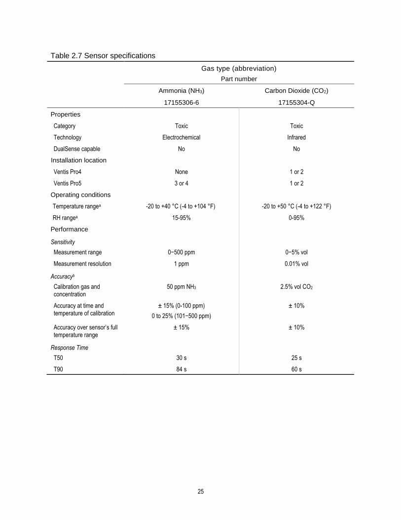
25
Table 2.7 Sensor specifications
Gas type (abbreviation)
Part number
Ammonia (NH3) Carbon Dioxide (CO2)
17155306-6 17155304-Q
Properties
Category Toxic Toxic
Technology Electrochemical Infrared
DualSense capable No No
Installation location
Ventis Pro4 None 1 or 2
Ventis Pro5 3 or 4 1 or 2
Operating conditions
Temperature rangea -20 to +40 °C (-4 to +104 °F) -20 to +50 °C (-4 to +122 °F)
RH rangea 15-95% 0-95%
Performance
Sensitivity
Measurement range 0−500 ppm 0−5% vol
Measurement resolution 1 ppm 0.01% vol
Accuracyb
Calibration gas and concentration
50 ppm NH3 2.5% vol CO2
Accuracy at time and temperature of calibration
± 15% (0-100 ppm)
0 to 25% (101−500 ppm)
± 10%
Accuracy over sensor’s full temperature range
± 15% ± 10%
Response Time
T50 30 s 25 s
T90 84 s 60 s

26
Table 2.7 Sensor specifications
Gas type (abbreviation)
Part number
Carbon Dioxide/LEL (Propane), IR
(CO2/LEL)
17155304-Uc
Properties
Category Toxic/Combustible
Technology Infrared
DualSense capable No
Installation location
Ventis Pro4 None
Ventis Pro5 2
Operating conditions
Temperature rangea -20 to +50 °C (-4 to +122 °F)
RH rangea 0-95%
Performance CO2 LEL
Sensitivity
Measurement range 0-5% vol 0-100% LEL
Measurement resolution 0.01% vol 0.01% LEL
Accuracyb
Calibration gas and concentration
2.5% vol CO2 25% LEL (Propane)
Accuracy at time and temperature of calibration
+10% or 0.1% +5%
Accuracy over sensor’s full temperature range
+15% +15%
Response Time
T50 17 s 17 s
T90 32 s 35 s

27
Table 2.7 Sensor specifications
Gas type (abbreviation)
Part number
Carbon Dioxide/Methane (CO2/CH4)
17155304-Vc and e
Properties
Category Toxic and Combustible
Technology Infrared
DualSense capable No
Installation location
Ventis Pro4 None
Ventis Pro5 2
Operating conditions
Temperature rangea -20 to +50 °C (-4 to +122 °F)
RH rangea 0-95%
Performance CO2 CH4
Sensitivity
Measurement range 0−5% vol 0−5% vol 5.01-100% vol
Measurement resolution 0.01% vol 0.01% vol 0.1% vol
Accuracyb
Calibration gas and concentration
2.5% vol CO2 2.5% vol 99% vol
Accuracy at time and temperature of calibration
± 10% ± 10% ± 10%
Accuracy over sensor’s full temperature range
± 15% ± 15% __
Response Time
T50 17 s 15 s 15 s
T90 32 s 30 s 30 s

28
Table 2.7 Sensor specifications
Gas type (abbreviation)
Part number
Carbon Monoxide (CO) Carbon Monoxide and Hydrogen Sulfide
(CO/H2S)
Carbon Monoxide and Hydrogen Sulfide
(CO/H2S)
17155306-1 17155306-J 17155304-J
Properties
Category Toxic Toxic Toxic
Technology Electrochemical Electrochemical Electrochemical
DualSense capable Yes Yes No
Installation location
Ventis Pro4 3 or 4 None None
Ventis Pro5 3 or 4 3 or 4 1 or 2
Operating conditions
Temperature rangea -40 to +50 °C (-40 to +122 °F)
-20 to +50 °C (-4 to +122 °F) -20 to +50 °C (-4 to +122 °F)
RH rangea 15-95% 15-95% 15-95%
Performance CO H2S CO H2S
Sensitivity
Measurement range 0-2000 ppm 0-1500 ppm 0−500 ppm 0-1500 ppm 0−500 ppm
Measurement resolution 1 ppm 1 ppm 0.1 ppm 1 ppm 0.1 ppm
Accuracyb
Calibration gas and concentration
100 ppm CO 100 ppm CO 25 ppm H2S 100 ppm CO 25 ppm H2S
Accuracy at time and temperature of calibration
± 5% ± 7%
± 10 %
± 5%
0 to 7%
Accuracy over sensor’s full temperature range
± 10% ± 5% ± 10% ± 5% ± 10%
Response Time
T50 10 s 15 s 10 s 15 s 10 s
T90 20 s 35 s 20 s 35 s 20 s

29
Table 2.7 Sensor specifications
Gas type (abbreviation)
Part number
Carbon Monoxide with low Hydrogen cross-sensitivity (CO/H2 Low)
17155306-G
Properties
Category Toxic
Technology Electrochemical
DualSense capable No
Installation location
Ventis Pro4 3 or 4
Ventis Pro5 3 or 4
Operating conditions
Temperature rangea -20 to +50 °C (-4 to +122 °F)
RH rangea 15-95%
Performance
Sensitivity
Measurement range 0−1000 ppm
Measurement resolution 1 ppm
Accuracyb
Calibration gas and concentration 100 ppm CO
Accuracy at time and temperature of calibration ± 5% (0-300 ppm)
± 15% (301-1000 ppm)
Accuracy over sensor’s full temperature range ± 15%
Response Time
T50 8 s
T90 12 s

30
Table 2.7 Sensor specifications
Gas type (abbreviation)
Part number
Chlorine (Cl2)
17155306-7f
Properties
Category Toxic
Technology Electrochemical
DualSense capable No
Installation location
Ventis Pro4 None
Ventis Pro5 3 or 4
Operating conditions
Temperature rangea -20 to +50 °C (-4 to +122 °F)
RH rangea 15–90%
Performance
Sensitivity
Measurement range 0–50 ppm
Measurement resolution 0.1 ppm
Accuracyb
Calibration gas and concentration 10 ppm Cl2
Accuracy at time and temperature of calibration ± 10% of reading or 0.3 ppm, whichever is greater (0–10.0 ppm)
± 20% (10.1–50.0 ppm)
Accuracy over sensor’s full temperature range ± 15%
Response Time
T50 6 s
T90 35 s

31
Table 2.7 Sensor specifications
Gas type (abbreviation)
Part number
Hydrocarbon, IR (Propane)
17155304-Pc
Properties
Category Combustible
Technology Infrared
DualSense capable No
Installation location
Ventis Pro4 2
Ventis Pro5 2
Operating conditions
Temperature rangea -20 to +50 °C (-4 to +122 °F)
RH rangea 0–95%
Performance
Sensitivity
Measurement range 0–100% LEL
Measurement resolution 1% LEL
Accuracyb
Calibration gas and concentration 25% LEL Propane
Accuracy at time and temperature of calibration
± 5% (0–25% LEL)
± 10% (26–50% LEL)
± 17% (51–100% LEL)
Accuracy over sensor’s full temperature range
± 17%
Response Time
T50 20 s
T90 45 s

32
Table 2.7 Sensor specifications
Gas type (abbreviation)
Part number
Hydrogen Cyanide (HCN)
17155306-B
Properties
Category Toxic
Technology Electrochemical
DualSense capable No
Installation location
Ventis Pro4 3 or 4
Ventis Pro5 3 or 4
Operating conditions
Temperature rangea -30 to +40 °C (-22 to +104 °F)
RH rangea 15-95%
Performance
Sensitivity
Measurement range 0−30 ppm
Measurement resolution 0.1 ppm
Accuracyb
Calibration gas and concentration 10 ppm HCN
Accuracy at time and temperature of calibration 0 to10%
Accuracy over sensor’s full temperature range ± 15%
Response Time
T50 18 s
T90 65 s

33
Table 2.7 Sensor specifications
Gas type (abbreviation)
Part number
Hydrogen Sulfide (H2S) Hydrogen Sulfide (H2S)
17155304-2 17155306-2
Properties
Category Toxic Toxic
Technology Electrochemical Electrochemical
DualSense capable No Yes
Installation location
Ventis Pro4 1 or 2 3 or 4
Ventis Pro5 1 or 2 3 or 4
Operating conditions
Temperature rangea -40 to +50 °C (-40 to +122°F) -40 to +50 °C (-40 to +122°F)
RH rangea 15-95% 15-95%
Performance
Sensitivity
Measurement range 0−500 ppm 0−500 ppm
Measurement resolution 0.1 ppm 0.1 ppm
Accuracyb
Calibration gas and concentration
25 ppm 25 ppm
Accuracy at time and temperature of calibration
± 5% (0-400 ppm)
± 7% (401-500 ppm)
± 7%
Accuracy over sensor’s full temperature range
± 15% ± 15%
Response Time
T50 10 s 10 s
T90 25 s 25 s

34
Table 2.7 Sensor specifications
Gas type (abbreviation)
Part number
LEL (Methane) LEL (Pentane)
17155304-L 17155304-K
Properties
Category Combustible Combustible
Technology Catalytic bead Catalytic bead
DualSense capable No No
Installation location
Ventis Pro4 2 2
Ventis Pro5 2 2
Operating conditions
Temperature rangea -20 to +55 °C (-4 to +131 °F) -20 to +55 °C (-4 to +131 °F)
15-95% RH rangea 15-95%
Performance
Sensitivity
Measurement range 0−100% LEL 0−100% LEL
Measurement resolution 1% LEL 1 % LEL
Accuracyb
Calibration gas and concentration
50% LEL methane 25% LEL pentane
Accuracy at time and temperature of calibration
± 3% LEL (0-50% LEL)
± 5% LEL (51-100% LEL)
± 5% LEL
Accuracy over sensor’s full temperature range
± 15% ± 15%
Response Time
T50 7 s 10 s
T90 10 s 16 s

35
Table 2.7 Sensor specifications
Gas type (abbreviation)
Part number
Methane, IR (CH4) Methane, 0-5% vol
17155304-Nc 17155304-M
Properties
Category Combustible Combustible
Technology Infrared Catalytic bead
DualSense capable No No
Installation location
Ventis Pro4 None 2
Ventis Pro5 2 2
Operating conditions
Temperature rangea -20 to +50 °C (-4 to +122 °F) -20 to +55 °C (-4 to +131 °F)
RH rangea 0−95% 15-95%
Performance
Sensitivity
Measurement range 0−5% vol 5.1-100% vol 0-5% vol
Measurement resolution .01% vol 0.1% vol 0.01% vol
Accuracyb
Calibration gas and concentration
2.5% vol methane 99% vol methaned 2.5% vol
Accuracy at time and temperature of calibration
± 5% ± 15%
± 10%
Accuracy over sensor’s full temperature range
± 10% ± 10% ± 15%
Response Time
T50 15s 15s 7 s
T90 25s 25s 10 s
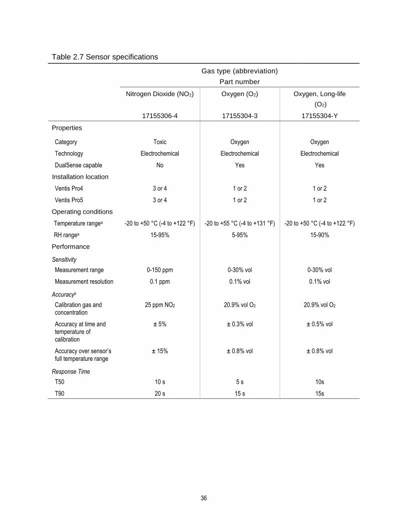
36
Table 2.7 Sensor specifications
Gas type (abbreviation)
Part number
Nitrogen Dioxide (NO2) Oxygen (O2) Oxygen, Long-life
(O2)
17155306-4 17155304-3 17155304-Y
Properties
Category Toxic Oxygen Oxygen
Technology Electrochemical Electrochemical Electrochemical
DualSense capable No Yes Yes
Installation location
Ventis Pro4 3 or 4 1 or 2 1 or 2
Ventis Pro5 3 or 4 1 or 2 1 or 2
Operating conditions
Temperature rangea -20 to +50 °C (-4 to +122 °F) -20 to +55 °C (-4 to +131 °F) -20 to +50 °C (-4 to +122 °F)
RH rangea 15-95% 5-95% 15-90%
Performance
Sensitivity
Measurement range 0-150 ppm 0-30% vol 0-30% vol
Measurement resolution 0.1 ppm 0.1% vol 0.1% vol
Accuracyb
Calibration gas and concentration
25 ppm NO2 20.9% vol O2 20.9% vol O2
Accuracy at time and temperature of calibration
± 5%
± 0.3% vol
± 0.5% vol
Accuracy over sensor’s full temperature range
± 15% ± 0.8% vol ± 0.8% vol
Response Time
T50 10 s 5 s 10s
T90 20 s 15 s 15s

37
Table 2.7 Sensor specifications
Gas type (abbreviation)
Part number
Oxygen, Long-life (O2)
17155306-Ye
Properties
Category Oxygen
Technology Electrochemical
DualSense capable No
Installation location
Ventis Pro4 3 or 4
Ventis Pro5 3 or 4
Operating conditions
Temperature rangea -20 to +50 °C (-4 to +122 °F)
RH rangea 15–90%
Performance
Sensitivity
Measurement range 0–30% vol
Measurement resolution 0.1% vol
Accuracyb
Calibration gas and concentration 20.9% vol O2
Accuracy at time and temperature of calibration ± 0.8% vol (0.0–5.0% vol)
± 0.5% vol (5.1–30.0% vol)
Accuracy over sensor’s full temperature range ±0.8% vol
Response Time
T50 10 s
T90 15 s

38
Table 2.7 Sensor specifications
Gas type (abbreviation)
Part number
Phosphine (PH3) Sulfur Dioxide (SO2)
17155306-9 17155306-5
Properties
Category Toxic Toxic
Technology Electrochemical Electrochemical
DualSense capable No Yes
Installation location
Ventis Pro4 3 or 4 3 or 4
Ventis Pro5 3 or 4 3 or 4
Operating conditions
Temperature rangea -20 to +50 °C (-4 to +122 °F) -20 to +50 °C (-4 to +122 °F)
RH rangea 15-90% 15-90%
Performance
Sensitivity
Measurement range 0-10 ppm 0-150 ppm
Measurement resolution 0.01 ppm 0.1 ppm
Accuracyb
Calibration gas and concentration 1 ppm PH3 10 ppm SO2
Accuracy at time and temperature of calibration
± 5% ± 5% (0-20 ppm)
0 to 11% (21-150 ppm)
Accuracy over sensor’s full temperature range
± 15% ± 10%
Response Time
T50 10s 10 s
T90 20s 25 s
aDuring continuous operation.
bApply when the instrument is calibrated using the stated calibration gas and concentration; unless otherwise stated, accuracy is equal to the stated percentage or one unit of resolution, whichever is greater. c The following sensors are not CSA-assessed for combustible gas detection: part numbers 17155304-N, 17155304-P, 17155304-U, and 17155304-V; however, these sensors are CSA-assessed: 17155304-K, 17155304-L, and 17155304-M. dRequires manual calibration. eNot approved for use in MSHA-certified instruments. f WARNING: Do not use the Ventis Slide-on Pump (VSP) when sampling for these target gases: Chlorine (CL2), Chlorine Dioxide (CLO2), Hydrogen Chloride (HCL), and volatile organic compounds (VOC), or when a sensor for any of these gases is installed and the target gas is unknown; use only the Ventis Pro Pump Module. The use of the VSP with these gases will result in inaccurate gas readings due to their susceptibility to absorption.
“—” indicates no available data.

3 Getting Started
Unpacking the Instrument
Hardware Overview
Display Overview
Power On
Power Off
Unpacking the Instrument
The items that are shipped with the instrument are listed below in Table 3.1. Each item should be accounted for during the unpacking process. If any item is missing or appears to have been damaged, contact Industrial Scientific (see back cover) or an authorized distributor of Industrial Scientific products.
Table 3.1 Package contents
Quantity Item Notes
1 as ordered Ventis® Pro Series instrument Ventis Pro4 or Ventis Pro5.
1 as ordered Battery (factory installed) One of four available rechargeable lithium-ion batteries.
1 Suspender clip (factory installed) —
1 Final Inspection & Test Report Includes informationa about the instrument and its installed sensors and factory calibration.
1 Quick Start —
As ordered Ventis Charger The universal power cord has four available plugs, one each for use with US, UK, EU, and AUS receptacles.
1 Calibration cup —
1 Calibration tubing 60.96 cm (2 ') of urethane tubing; 4.762 mm (3/16 ″) ID.
aAt the time of shipment.
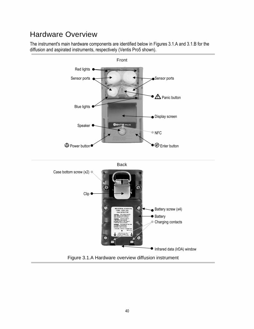
40
Hardware Overview The instrument's main hardware components are identified below in Figures 3.1.A and 3.1.B for the diffusion and aspirated instruments, respectively (Ventis Pro5 shown).
Front
Red lights
Sensor ports Sensor ports
Panic button
Blue lights
Display screen
Speaker
NFC
Power button Enter button
Back
Case bottom screw (x2)
Clip
Battery screw (x4)
Battery
Charging contacts
Infrared data (IrDA) window
Figure 3.1.A Hardware overview diffusion instrument

41
Front
Inlet
Cap
Pump door hinge Barrel (houses water barrier)
Pump door screw
Pump door
Panic button
Red lights
Blue lights
Speaker Display screen
NFC
Power button Enter button
Infrared data (IrDA) window
Back
Pump case (lower portion houses battery)
Pump case screw (x4)
Figure 3.1.B Hardware overview aspirated instrument

42
Display Overview The instrument’s easy-to-read display screen has three main horizontal segments. From top to bottom, they are:
• Status bar
• Gas readings area
• Navigation bar
The instrument uses these areas to display symbols, numbers, abbreviations, and text in combinations that allow it to clearly communicate with its user: the instrument operator in the field or team members who are responsible for maintaining the instrument.
See Figures 3.2.A through 3.2.D to become familiar with the display screen layout and content items the user can expect to see at these times:
• During operation
• In the event of a warning or alarm
• During maintenance
• While working in settings
Status bar
During operation, the display screen’s status bar communicates basic information to the instrument operator: instrument and battery status (shown), ambient-air temperature, and the time of day. When the instrument is in a LENS group, the number of equipment items is shown along with the group's signal quality. Cloud symbols are used to indicate the instrument's iNet connection status.
Instrument status symbol
The status bar checkmark indicates the instrument is operational.
Wi-fi status
A wi-fi battery is installed and connected to a network (strongest signal quality shown here with three bars).
A wi-fi battery is installed, but its wireless and GPS features are not operational.
LENS Wireless status
5 and
Indicates the LENS Wireless group peer count and the group's signal quality network (strongest signal quality shown here with four bars).
LENS Wireless is not operational.
LENS Wireless is set to "off" and LENS Wireless features are not available.

43
iNet Now status
no cloud The instrument’s firmware version, settings, or LENS Wireless status make it unavailable for live monitoring by users of iNet Now.
or
The instrument is wirelessly connected to iNet; it is available for live monitoring by users of iNet Now.
The instrument is not wirelessly connected to iNet; it is unavailable for live monitoring by users of iNet Now.
The instrument is wirelessly connected to iNet via a smart-device gateway; while it is available for live monitoring by users of iNet Now, the instrument-to-smart device wireless connection is weak.
Other symbols
The instrument’s man-down feature is not operational.
Name User name assigned to peer instrument readings.
Pump installed.
The battery’s level of charge is between 67and 100%.
The battery’s level of charge is between 34 and 66%.
The battery’s level of charge is less than or equal to 33%.
The battery’s level of charge is approaching a critically low level.
11:34a The time of day (12-hour format shown).
76 F The ambient-air temperature reading (Fahrenheit shown).
Gas readings area
In addition to the display of current gas readings, this area communicates status information about the installed sensors.
Gas reading
Gas, unit of measure, and current reading.
Other symbols
The Alarm Silencer accessory is attached, man-down and gas detection alarm signals are suspended.
The indicated sensor is in a general state of failure.
The indicated sensor failed zeroing.
CAL The indicated sensor failed calibration.

44
BUMP The indicated sensor failed bump testing.
ERR The indicated sensor is installed in the wrong location.
Navigation Bar
During operation, there may be information screens or maintenance utilities available to the instrument operator. If so, the bottom area of the display screen will feature the navigation bar. The action displayed on the left is controlled by the button underneath it, the
power button ; the action on the right is
controlled by the enter button .
Instructional symbols and text
Start the option (bump test utility shown above).
Skip the option and go to the next display screen.
Clear values.
Figure 3.2.A Reading the display during operation
Clear

45
Status bar
Gas readings area
Full-screen alarm format
Peer alarm
In the event of an instrument warning or alarm, the gas readings area communicates the event type, details about the alarm, and gas readings for all sensors.
Peer events use symbols that are similar to instrument-event symbols. When shown in the status bar, they are generally white on a black background; when shown in the gas readings area, the word "peer" will display.
Event symbols (gas-related)
and Gas present, over-range alarm
and Gas present, high-alarm
and Gas present, low-alarm
Gas present, alert (warning)
Short-term exposure limit (STEL) alarm
Time-weighted average (TWA) alarm
Alarm is latched
Other symbols (nongas-related, full-screen symbol)
Critical low battery
Indicates the in-alarm instrument is a Ventis Pro Series monitor.
Indicates the in-alarm peer instrument is a Radius BZ1 Area Monitor.
; Panic alarm; peer panic alarm
; Man-down alarm; peer man-down alarm
Peer Name A peer equipment item has lost its wireless connection to the LENS group.
Group Lost The instrument is no longer wirelessly connected to any LENS group equipment item.
No Peers All equipment items have left the group.
System error (408 shown)
Figure 3.2.B Reading the display during an event (warning or alarm)

46
Status bar
The display screen’s status bar indicates which maintenance procedure is in progress (bump test utility shown here).
Utility symbols
Bump test utility
Zero utility
Calibration utility
Process in progress
Gas readings area
The gas readings area communicates information about the process and results for any maintenance procedures (bump test utility shown here).
Other symbols
Calibration gas type, unit of measure, and concentration
Results
Passed
Failed
Navigation Bar
The navigation bar provides instruction. The action displayed on the left is controlled by the button underneath it, the power button ; the action on the right is controlled by the enter button .
Instructional symbols
Cancel the utility (bump test shown here).
Start the utility.
Apply the calibration gas.
Figure 3.2.C Reading the display during maintenance

47
Status bar
When working in settings, the status bar may indicate the setting name (H2S settings shown here).
Multi-item setting
Single-item setting
Editing area
The editing area displays the settings' values. The highlight bar indicates which setting is being edited (gas-alert value shown here).
Navigation bar
The navigation bar provides instruction for navigating settings. The action displayed on the left is controlled by the button underneath it, the power button ; the action on the right is controlled by the enter button .
Status bar symbol
Settings.
Other symbols
Current setting.
Go to the next setting.
Edit the setting.
Edit the setting.
Scroll an options list.
Exit.
X.Y "X" indicates the display screen's menu number; "Y" indicates its setting number.
Figure 3.2.D Reading the display while working in settings
In addition to the items described above, the Ventis Pro Series’ display will also feature, when relevant, the gas names, units of measure, and other symbols shown below.
Gas names
CH4 CH4 (Methane)
CO Carbon Monoxide
CO2 CO2 (Carbon Dioxide)
H2S H2S (Hydrogen Sulfide)
HCN Hydrogen Cyanide
Edit
ON

48
LEL Combustible gases
NH3 NH3 (Ammonia)
NO2 NO2 (Nitrogen Dioxide)
O2 O2 (Oxygen)
SO2 SO2 (Sulfur dioxide)
Units of measure
ppm Parts per million.
mg/m3 Milligrams per cubic meter.
% LEL The lower explosive limit (LEL) is the minimum concentration of a gas, which, if given an ignition source, is capable of producing a flash of fire.
% vol Percent by volume refers to a defined amount of the gas in 100 parts of air. For example, normal air contains 21% vol oxygen, or 21 parts oxygen in every 100 parts of air.
Other symbols
The Alarm Silencer accessory is attached, man-down and gas detection alarm signals are suspended.
Present when GPS coordinates are being received via satellite; otherwise, the coordinates indicate the last-received GPS location.
Yes.
No.
Maintenance due (calibration shown).
The down arrow indicates the number of days since the maintenance procedure was last completed. The up arrow indicates the number of days until the maintenance procedure is next due. or
Peak readings.
Used with peer messages to indicate the peer instrument is a Radius BZ1.
Used to identify an instrument's assigned (or available) user name. Also used with peer messages to indicate the peer instrument is a Ventis Pro Series instrument.
Used to identify an instrument's assigned site name.
Return the instrument to Industrial Scientific.
Security code is required.
Data exchange or synchronization may be in progress.
Indicates that the sensor is operating on DualSense technology.
A sensor that was operating on DualSense has failed.
A sensor operating on DualSense is due for maintenance (sensor 1 shown here).

49
Power On If a pump is installed, complete the following pump preparation steps before powering on the instrument.
If the use of the integrated pump is desired, but has not been installed, see Figure 8.3 Service Tasks for pump installation instruction.
— —
Attach one end of the sample tubing to the pump inlet's nipple (left); attach the other end to a compatible water stop (right).
At each end, push on the tubing to ensure the connecting part is fully inserted into the tubing (approximately .635 cm [.25 "]). To test for a firm connection, gently pull on the tubing.
To power on the instrument, press and hold the power button for approximately three seconds, until the blue lights flash. The instrument will perform a self-test; its operator should observe the instrument and its display screen to verify the unit is operating as expected (see Figure 3.3 below).
Immediately following the self-test is the start-up sequence, which will provide information and may prompt the worker to prepare the instrument for use. Preparation and utility options included in the start-up sequence may vary from those shown below depending on instrument settings and functionality.
At the end of the power-on process, the home screen will display.
Self-test
Light test Display test Audible and vibration test Sample error message
The blue lights will flash followed by the red lights. Verify that all lights are functional.
Observe the display screen to verify that all pixels are functional.
The instrument will vibrate and then emit a loud beep. Verify that both signal types are functional.
If the instrument fails any part of its self-test, an error message will display. If the instrument or its operator detect problems, contact Industrial Scientific for assistance.
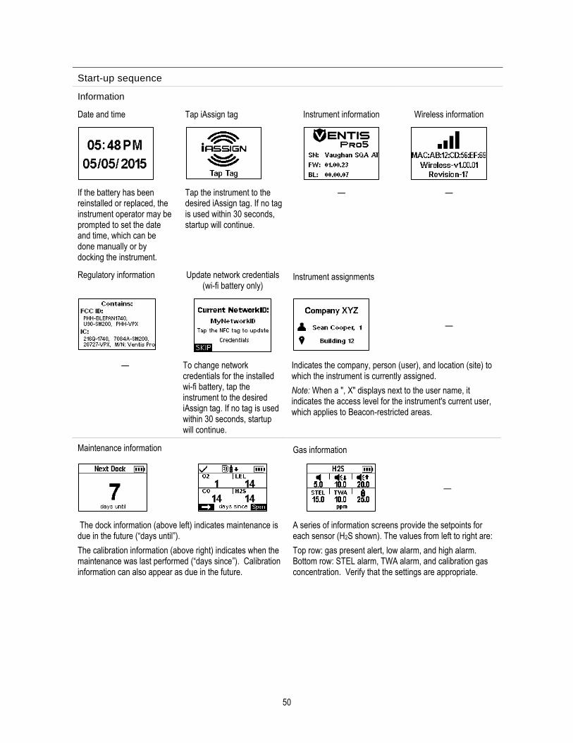
50
Start-up sequence
Information
Date and time Tap iAssign tag Instrument information Wireless information
If the battery has been reinstalled or replaced, the instrument operator may be prompted to set the date and time, which can be done manually or by docking the instrument.
Tap the instrument to the desired iAssign tag. If no tag is used within 30 seconds, startup will continue.
— —
Regulatory information Update network credentials (wi-fi battery only)
Instrument assignments
—
— To change network credentials for the installed wi-fi battery, tap the instrument to the desired iAssign tag. If no tag is used within 30 seconds, startup will continue.
Indicates the company, person (user), and location (site) to which the instrument is currently assigned.
Note: When a ", X" displays next to the user name, it indicates the access level for the instrument's current user, which applies to Beacon-restricted areas.
Maintenance information Gas information
—
The dock information (above left) indicates maintenance is due in the future (“days until”).
The calibration information (above right) indicates when the maintenance was last performed (“days since”). Calibration information can also appear as due in the future.
A series of information screens provide the setpoints for each sensor (H2S shown). The values from left to right are:
Top row: gas present alert, low alarm, and high alarm. Bottom row: STEL alarm, TWA alarm, and calibration gas concentration. Verify that the settings are appropriate.

51
Preparation and utilities
Start-up message Compliance check
(German-language instruments only)
Read and understand
the message.
If a pump has been installed, the instrument will prompt its operator to complete the following pump test.
Acknowl-edge
message.
Answer "no". Answer "yes".
Pump test
Block inlet Wait
—
When prompted, use your thumb to block the end of the sampling line, the water-stop opening.
While the test is in progress, the display screen will ask the instrument operator to wait. Next, the test results will be displayed as "Passed" or "Failed".
Test results: Passed Test results: Failed*
Unblock the water-stop opening.
Restart the pump: Press .
It may take several seconds for the pump to restart.
Unblock the water-stop opening.
—
Power off the instrument.
*Note: A failed pump test may indicate a problem somewhere in the sampling line. Check and correct for cracks or other damage, debris, and improper installation in these areas: all sampling line connections and the pump's inlet cap, inlet barrel, and dust filter.
Zero utility Bump test utility
—
Skip the utility: wait 15
seconds.
Skip the utility: wait
15 seconds.
Start the utility.
Start the utility.

52
Home
Wi-fi status LENS Wireless (peer count and group signal quality)
No fault status symbol
Home (five-gas instrument)
iNet Now status
Battery status (shown), temperature, and time
Gas name
Home (four-gas instrument)
Unit of measure
Current gas reading
Figure 3.3 Power on
Power Off
If the instrument is set to remain on, power off may require the entry of the unit’s security code.
Home Countdown Enter security code
— —
Start power-off countdown.
Hold for the full five-second countdown.
Enter the diplayed value.
Edit the displayed value.
Figure 3.4 Power off
Quick-status information
When the instrument is powered off, the installed sensors, available battery power, and instrument serial number can be viewed without powering on the
instrument: simultaneously press and hold and for two seconds.

4 Settings
Guidelines
Accessing Settings
Settings Menus
Examples for Working in Settings
Reviewing and Editing Settings
Guidelines
Settings that can be adjusted manually through the instrument are described in this Product Manual. These and other settings can also be adjusted through compatible Industrial Scientific docking stations and accessories supported by iNet Control, DSSAC, and Accessory Software; any changes made manually to the instrument will be overridden when the instrument is docked.
Only qualified personnel should access and adjust instrument settings; this person is referred to below as the "safety specialist". To help guard against unintended access by nonqualified personnel, settings can be security-code protected.
Accessing Settings Settings can be accessed while the instrument is powering on—during the start-up sequence—by simultaneously pressing then releasing and . If the security-code screen is activated, settings are protected and the instrument's security code must be entered. If the entered value matches the instrument's security code, the first settings menu (1.0 Maintenance) will display; otherwise, access to settings will be denied and the instrument will resume start-up.
— —
Press Press Press Press
Enter the displayed
value.
Edit the value.
Next menu Start maintenance

54
Settings Menus A menu system is used to organize instrument settings by topic. This allows the safety specialist to first choose the menu (topic) of interest, such as alarms, then review and optionally "edit" (adjust) each available setting within that menu. Table 4.1 summarizes the settings that are available in each menu.
Table 4.1 Settings menus
Menu number and topic Settings summary
1.0 Maintenance A primary purpose of the maintenance menu is to provide the safety specialist with access to maintenance procedures (utilities). Menu options also include NFC and Bluetooth settings, which are needed for an instrument that will use iAssign® accessories or will send instrument data to the iNet Now Sync App, respectively.
2.0 Start-up These settings allow the safety specialist to permit or prohibit all-user access, from the startup sequence, to various functions and assignments. Access is set separately for each item.
3.0 Operation The operation menu allows the safety specialist to permit or prohibit—during instrument operation—all-user access to utilities and maintenance status information. Access is set separately for each item. From here, the specialist can also permit or prohibit the use of iAssign tags during instrument operation.
4.0 Alarm Alarm settings allow the safety specialist to set the values for each gas event that will cause the instrument to alarm.
The specialist can also permit or prohibit instrument power off during alarms and make other choices about alarm- and warning-related instrument behavior.
5.0 Sensor Sensor settings allow the safety specialist to view basic information about the installed sensors and control settings related to calibration and bump test utilities.
6.0 Admin
(Administration)
Admin settings allow the safety specialist to control important aspects about how the instrument communicates with its operator. For example, a security code can be set to help restrict all-user access to settings.
The safety specialist can also set the display-screen language, maintenance-related warnings, and other items.
7.0 Wireless Wireless settings allow the safety specialist to turn on or off LENS Wireless and to choose settings for LENS' group-related warnings and data encryption.
The specialist can also make choices about the instrument’s iNet related and wi-fi battery settings.
Examples for Working in Settings Two examples are provided below to illustrate how to navigate in and adjust settings.
Each example includes a goal, a target setting that is to be changed; the navigation path that leads to the target setting; and instruction to change the target setting.
Example 1 features a single-item setting—a setting that has a value of “on” or “off”.
Example 2 features a multi-item setting where the value for each of several items can be changed—one item at a time.
Example 1. Editing a single-item setting
Goal: Latch the instrument's alarms

55
• From the 1.0 Maintenance menu, navigation leads to the 4.0 Alarm menu where the alarm-latch setting resides. Along the way, the navigation bypasses menus 1.0, 2.0, and 3.0.
• From the 4.0 Alarm menu, navigation leads to the setting, “Alarm Latch”. Along the way, other alarm settings are bypassed and their values remain unchanged.
• At the alarm-latch setting, the value is changed from “off” to “on”.
Press
Go to the next menu
Press
Go to the next menu.
Press
Go to the next menu.
Press
Go to the first setting option within the alarm menu.
—
Press
Bypass the Audio Alarm setting.
Press
Bypass the Vibrating Alarm setting.
Press
Edit the setting: change the Alarm Latch value from "off"
to "on".
Press
Go to the next setting.
Figure 4.1.A Example for editing a single-item setting
Example 2. Editing a multi-item setting
Goal: Change the high-alarm setpoint for H2S.
• Follow the navigation from Example 1 above.
• The navigation shown below then bypasses setpoints for the O2, LEL, and CO sensors; their values remain unchanged.
• The H2S event setpoint screen is a five-item setting. The navigation bypasses the first two settings, the gas-alert and low-alarm setpoints; their values remain unchanged.
• The H2S high-alarm setpoint is then highlighted for editing. Its value is changed from 20.0 ppm to 19.0 ppm.
Edit

56
Press
Bypass the settings for O2.
Press
Bypass the settings for LEL.
Press
Bypass the settings for CO.
Press
Highlight the first setpoint for H2S (gas alert).
—
Press
Bypass the gas-alert setting.
Press
Bypass the low-alarm setting.
Press
Edit the value for the high-alarm setpoint.
Press the button until the desired value of 19.0 is
displayed.
Press
Save the new high-alarm setpoint value; go to the next H2S setting.
— —
Press
Bypass the STEL alarm setting.
Press
Bypass the TWA alarm setting.
Figure 4.1.B Example for editing a multi-item setting
Reviewing and Editing Settings The rest of this chapter describes in detail the settings and options available within each menu. Instruction is provided for navigating each menu and adjusting its settings.
When navigating and editing settings, the instrument will wait approximately 60 seconds between button presses; when no button is pressed, it will exit settings and re-enter start-up. To return to settings from start-up, simultaneously press and hold, then release and .

57
Maintenance menu
The maintenance menu options related to these topics:
• Utilities and instrument information
• User-site assignments, iAssign, and iNet Now
Utilities and instrument information
Perform any of these utilities:
• Zero the installed sensors.
• Calibrate the instrument.
• Bump test the installed sensors.
• View and optionally reset to zero each summary reading (peak, TWA, or STEL reading). When any summary reading is reset to zero, its time-related setting is also reset to zero.
Locate this basic instrument information:
• View the model, serial number, firmware version, and boot loader version.
• View regulatory and wireless information.
• Learn when the instrument is next due for docking or calibration or when it was last calibrated.
User-site assignments
View the instrument's user and site assignments, and optionally change those assignments from the list of available values. If the desired user or site is not listed, use iNet Control or an iAssign accessory to complete the assignment.
Note: When a user or site assignment is made to the instrument using iNet Control, DSSAC, or Accessory Software, the instrument classifies the entered user or site as a recurring assignment. When an assignment is made to the instrument using an iAssign accessory, the instrument treats it as a temporary assignment.
NFC
When set to on, NFC (near field communication) permits the instrument to do the following.
• Use “pairing” to join any LENS group, an unnamed, ad hoc formed group or a named group.
• Accept data from iAssign accessories. If the iAssign Beacon is in use, see also "Bluetooth" (below).
• Suspend gas detection and the man-down alarms when the Alarm Silencer accessory is attached.
Use the "Clear iAssign" setting to control how iAssign data are to be cleared from the instrument. Choose from these options:
• Select "Overwrite" to allow iAssign accessories to overwrite the instrument's user, site, and access-level data. This setting is suitable for applications where workers are to use iAssign accessories in the field to change the instrument's current assignments.
• Select "Restart" or "Charging" to allow the instrument's user, site, and access-level data to be cleared only when the instrument experiences a restart or charging event, respectively.
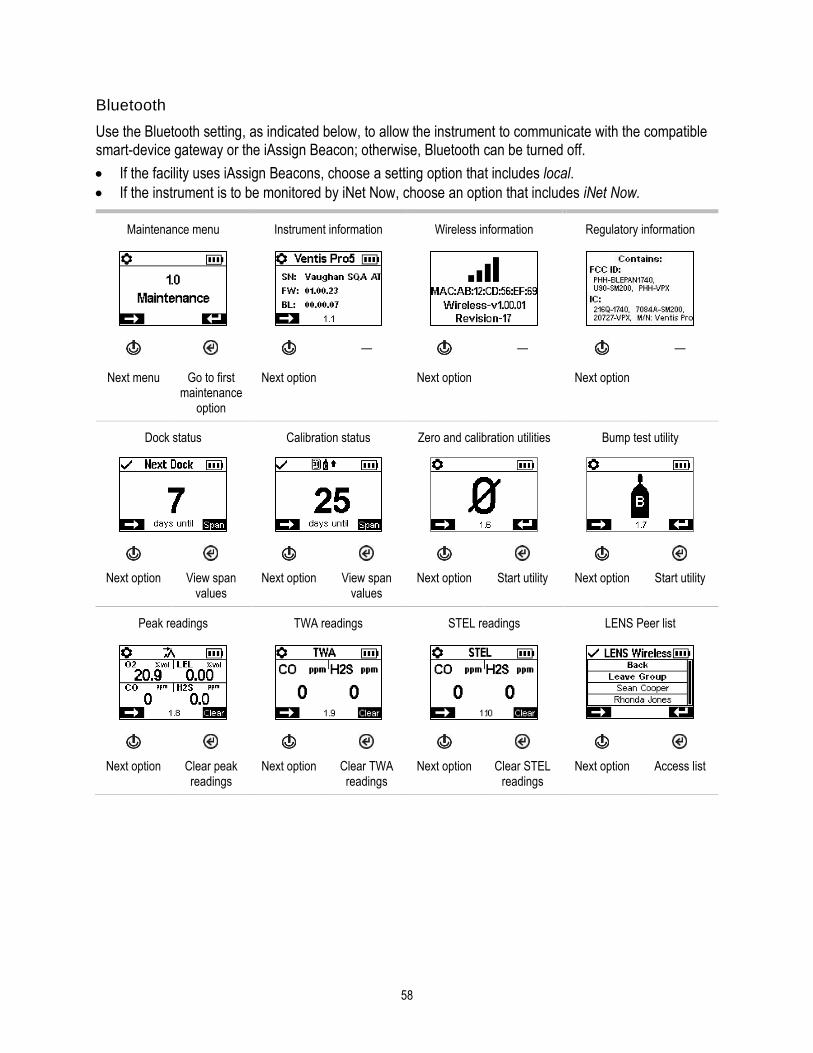
58
Bluetooth
Use the Bluetooth setting, as indicated below, to allow the instrument to communicate with the compatible smart-device gateway or the iAssign Beacon; otherwise, Bluetooth can be turned off.
• If the facility uses iAssign Beacons, choose a setting option that includes local.
• If the instrument is to be monitored by iNet Now, choose an option that includes iNet Now.
Maintenance menu Instrument information Wireless information Regulatory information
— — —
Next menu Go to first maintenance
option
Next option Next option Next option
Dock status Calibration status Zero and calibration utilities Bump test utility
Next option View span values
Next option View span values
Next option Start utility Next option Start utility
Peak readings TWA readings STEL readings LENS Peer list
Next option Clear peak readings
Next option Clear TWA readings
Next option Clear STEL readings
Next option Access list

59
Near-field communications (NFC; required for iAssign tags
and Alarm Silencer accessory)
Bluetooth If the facility uses iAssign Beacons,
choose an option that includes "local". If the instrument is to be monitored by iNet Now, via a smart-device gateway, choose an option that includes "iNet
Now".
User assignment User assignment options (current user highlighted)
Next option Turn on or off
Next option Choose connection
type
Next option Edit current user
Scroll user list
Set user
Site assignment Site assignment options (current site highlighted)
User-site assignment reset End of menu
Next option Choose connection
type
Scroll site list
Set site Next option Set functionality
Revisit maintenance
options
Access menus or
exit settings
Figure 4.2.A Navigating and using maintenance options

60
Start-up menu
Control how the instrument will interact with its operator during start-up.
Prompt or don't prompt for the use of an iAssign tag for user-site data.
Prompt or don't prompt for the use of an iAssign tag to update network credentials for an instrument that is equipped with a wi-fi battery.
Permit or prohibit all-user access to each item listed below.
Maintenance utilities:
o Zero the installed sensors. o Bump test the installed sensors.
Maintenance status message:
o No message. o The number of days until the next dock is due. o The number of days until the next calibration is due. o The number of days since calibration was last performed.
Start-up menu Zero on start-up Bump test on start-up Maintenance status on start-up
Next menu Go to first start-up setting
Next setting Set access Next setting Set access Next setting Set access and format
Prompt for iAssign tag use on start-up
Prompt for wi-fi network credentials on start-up
End of menu
—
Next setting Turn on or off
Next setting Turn on or off
Revisit start-up settings
Access menus or
exit settings
Figure 4.2.B Navigating and editing start-up settings
61
Operation menu
Control how the instrument will behave during operation.
Permit or prohibit all-user access, during operation, to each of the items listed below.
Utilities:
o Zero the installed sensors. o Calibrate the instrument. o Bump test the installed sensors. o View and optionally clear each summary reading (peak, TWA, or STEL). Note: When an instrument
operator clears any summary reading, the value is reset to zero and its time-related setting is also reset to zero. Note: If a CO2 sensor is installed, it will be zeroed along with any other installed sensors only if the "Zero CO2" setting is on.
Information:
o The instrument's current assignments for user, site, or both o A maintenance message about scheduled docking or calibration activities o The gas information for all installed sensors: the values for the gas alert and alarm setpoints, and
the calibration gas and concentration
Set this functionality
• Permit or prohibit all-user access to the instrument's LENS Wireless peer list.
• Permit or prohibit the use of iAssign accessories during operation.
• Permit all-user power off or set the instrument for "always-on" operation*.
• Set the instrument to display the ambient air temperature in Celsius or Fahrenheit.
*Always-on functionality also requires a valid security code setting (see the settings menu 6.0 Admin).

62
Operation menu Wireless peer list Instrument assignment information
Maintenance status
Next menu Go to first operation
setting
Next setting Set all-user access
Next setting Set all-user access
Next setting Set all-user access and
format
Zero and calibrate Zero CO2 Bump test Clear peak readings
Next setting Set all-user access
Next setting Include sensor for
zero
Next setting Set all-user access
Next setting Set all-user access
Clear TWA and STEL readings
Gas settings information iAssign functionality Temperature display
Next setting Set all-user access
Next setting Set all-user access
Next setting Set all-user functionality
Next setting Set unit of measure
Always-on functionality End of menu
— —
Next setting Set functionality
Revisit operation settings
Access menus or exit settings
Figure 4.2.C Navigating and editing operation settings

63
Alarm menu
Control how the instrument will behave during alarms and some warnings.
Set for each sensor, the concentration of gas that will cause each possible gas event listed below.
• gas present, alert
• gas present, low alarm
• gas present, high alarm
• TWA
• STEL
Note: The navigation will start with the first setpoint for the first sensor; then the second setpoint for that same sensor, and so on through the last setpoint for the sensor. The navigation will then go through the same pattern for the next sensor.
Set the TWA time interval for toxic sensor readings.
Permit or prohibit instrument power off during alarms.
Set the on-off functionality for the man-down feature; set the amount of time that will lapse between the man-down warning and its alarm.
Set the on-off functionality for the proximity alarm. When set to on, the instrument proximity alarm is activated when the instrument enters an iAssign Beacon restricted-access area where the access-level setting of the Beacon is higher than that of the instrument's current user assignment. User access-level settings can be edited using the iAssign app or through iNet. When edited through the iAssign app, the change is immediate upon tapping the adjusted iAssign tag to the instrument. iNet changes take effect after an instrument is next docked.
Set the on-off functionality for each option listed below.
• audible alarm
• vibrating alarm
• full-screen alarms
• gas-present alert
• alarm latch
• alarms while docked
Alarm menu Audible alarm Vibrating alarm Alarm latch
Next menu Go to first alarm setting
Next setting Turn on or off
Next setting Turn on or off
Next setting Turn on or off
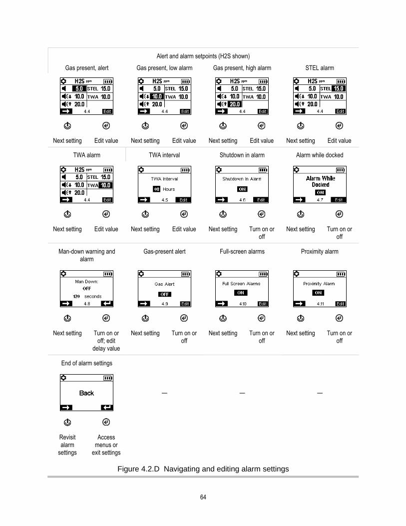
64
Alert and alarm setpoints (H2S shown)
Gas present, alert Gas present, low alarm Gas present, high alarm STEL alarm
Next setting Edit value Next setting Edit value Next setting Edit value Next setting Edit value
TWA alarm TWA interval Shutdown in alarm Alarm while docked
Next setting Edit value Next setting Edit value Next setting Turn on or off
Next setting Turn on or off
Man-down warning and alarm
Gas-present alert Full-screen alarms Proximity alarm
Next setting Turn on or off; edit
delay value
Next setting Turn on or off
Next setting Turn on or off
Next setting Turn on or off
End of alarm settings
— — —
Revisit alarm
settings
Access menus or
exit settings
Figure 4.2.D Navigating and editing alarm settings

65
Sensor menu
Depending on the installed sensors, display screens may vary.
Control settings related to calibration and bump testing:
• Choose the "quick" or "standard" process for calibration and bump testing.
Quick process. This process allows for only one application of gas. It is well suited for installed sensor combinations that use a calibration gas cylinder of the "blended" type—one that contains the gas types and concentrations required for all installed sensors. Standard process. This process allows for more than one application of gas. It provides time—between sensors—for the change of cylinders. It is well suited for installed sensor combinations that require more than one calibration gas cylinder.
• Set calibration gas concentrations for each sensor and the correlation factor for an LEL sensor.
View the location of each installed sensor and its span reserve percentages. Note: An indicator of a sensor's remaining life, the span reserve percentage will decline over time; when its value is less than 50%, the sensor will no longer pass calibration.
Each sensor has a deadband value, which allows it to measure the low-level presence (or lack) of a gas, but display a reading of zero. For example, if the deadband value for a CO sensor is 3 ppm, any positive CO measurement up to and including +3 ppm will produce a display-screen reading of 0 ppm. Likewise, a negative CO measurement down to and including -3 ppm will produce a reading of 0 ppm.
To allow the instrument to display as zero any gas measurements within the deadband, set the deadband to on. To allow the instrument to display the sensor’s actual reading when the detected level of gas is within the deadband, set the deadband to off.

66
Sensor menu Installed sensor locations Span reserve percentage values
Bump test and calibration process type
— —
Next menu Go to first sensor setting
Next setting Next setting Next setting Set for quick or standard
Calibration values for LEL sensor
LEL correlation factor Calibration gas concentrations (non-LEL sensors and dual-range IR sensor)
Next setting Set calibration gas values
Next setting Edit value Next setting Edit value Next setting Edit value
Toxic gas unit of measure (available for select
language configurations)
Deadband End of menu
—
Next setting Set unit of measure
Next setting Turn on or off
Revisit sensor settings
Access menus or
exit settings
Figure 4.2.E Navigating and editing sensor settings

67
Admin menu
Control the ways in which an instrument will interact with its user and set time-based values that are related to the data-log entries and bump testing.
To help protect access to settings, set the instrument's security code value to any three-digit number from 001 to 999. A value of 000 will leave settings unprotected and potentially accessible all instrument users.
A security code of 001-999 is also required for the use of always-on functionality; if set to 000, an always-on unit can be powered off without a security code.
Sensors pass a bump test when they sense the specified percentage of calibration gas (or "pass limit") within the specified response-time setting. Set the bump test criteria for these two values:
• a pass limit value from 50 to 99%
• a response-time value from 30 to 120 seconds
Note: For calibration gas recommendations, see "Table 2.7, Sensor specifications".
Turn on or off each of these warnings: scheduled bump test due, scheduled calibration due, and scheduled dock (or "synch") due. For each warning that is set for on, set these two values:
• a warning type of audible only, visual only, or both audible and visual
• the maintenance interval (set in one-day increments for dock and calibration and half-day increments for bump test)
The confidence indicator emits a signal every 90 seconds to indicate to the user and others who are nearby that the instrument is powered on. If the indicator is set for on, choose a signal type of audible only, visual only, or both audible and visual.
Set the LENS Warning to off or to on. When set to on, the instrument will warn its operator that it is not part of LENS group.
Set the iAssign warning to off or to on for user only, site only, or user and site. When set to on, the instrument will warn its operator of missing assignments.
Set the iAssign update to on or off. When set to on, the instrument notifies its user when iAssign user-site settings are changed.
Set the instrument's display language.
To support data-log integrity, set the date and time; these values are associated with gas-readings and event data that are saved to the data log.

68
Admin menu Security code Confidence indicator Scheduled maintenance warnings
Next menu Go to first admin setting
Next setting Edit value Next setting Turn off warning or set warning
type
Next setting Turn off warnings or set warning
types
Maintenance intervals Bump test criteria Display-screen language Current date
Next setting Set interval (days)
Next setting Edit percentage
and time
Next setting Choose display-screen
language
Next setting Edit values
Current time iAssign warning iAssign update tone LENS warning
Next setting Edit values Next setting Turn off warning or set warning
type
Next setting Turn on or off
Next setting Turn on or off

69
End of menu
Revisit sensor settings
Access menus or
exit settings
Figure 4.2.F Navigating and editing admin settings
Wireless menu
Control how the instrument will operate with respect to LENS Wireless functionality and iNet communications.
Set the LENS Wireless mode.
• If the instrument will not use LENS Wireless, choose off.
• If the instrument will use LENS Wireless, but will not be monitored by iNet Now, choose Local.
• If the instrument will use LENS Wireless and will be monitored by iNet Now*, choose the combined option, iNet Now and local.
*Requires activation of the iNet Now service, plus instrument activation (using iNet) for live monitoring.
Use the LENS Group setting, which controls how the instrument can join these groups, as described below. The options are Scan, Manual, or a named group such as Group A.
• Choose the setting value of "Scan" to allow the instrument to scan for and automatically join a LENS group. The instrument will scan for LENS groups within range, selecting the best group to join based on network strength and number of LENS peers in the group. The instrument will continue to scan until it detects and joins an available LENS group with a vacancy..
Note: In Scan mode, with LENS Wireless set to iNet Now and local, the instrument will scan until a group containing a Gateway is found and a connection to iNet (via a LENS group) is established.
• If the worker is expected to join and leave LENS groups as needed, choose the setting value of "Manual". This allows the instrument to use NFC pairing to manually join a group, so ensure the NFC setting is on (see Maintenance settings menu) when selecting this value.
Note: A setting value of scan or manual will permit the instrument to join any LENS group─an unnamed, ad hoc formed group or a named group (e.g., Group X).
• If the instrument does not need to join and leave different LENS groups, you can assign it to a named group, such as "Group A”. When set to a named group, an instrument cannot join any other LENS group without changing the setting to Scan, Manual, or a different named group.
Note: The named group setting value options are “A” through “J”.

70
Determine how the instrument interacts with its user about LENS peer alarms and warnings.
• Set the instrument's peer alarm off or set its signal type to audible only, visual only, or both audible and visual. When set to off, peer alarms will be indicated only on the display screen.
• Set the instrument's peer-lost and no-peer warnings to on or off. When set to off, the instrument will not in any manner warn or notify its operator of these occurrences.
Control wi-fi battery operation.
Set the wi-fi on or off.
• Use a setting of off to allow the battery to power the instrument, but to disallow its wireless functionality. When off, GPS is disabled.
• Use a setting of on to allow the battery to power the instrument and to allow wireless communication with iNet. When on, GPS coordinates and instrument data are immediately transmitted to iNet when any of these alarms and errors occur.
Alarms o Gas present, low alarm o Gas present, high alarm o Gas present, over-range (positive and negative) o TWA o STEL o Man-down o Panic o Proximity o Critical error Set the “message interval”, the interval at which the wi-fi battery will collectively transmit data about these occurrences. The interval value range is from 15 to 300 seconds.
Process status o Zero failure o Calibration failure o Bump test failure
Updates o User name o Site name
Determine how the instrument notifies its user of a lost iNet connection. Set the iNet Now connection-lost warning signal to visual or visual and audible.
When set to on, the sync-while-charging option applies only when the Ventis Pro is being monitored by an in-range smart-device, not the RGX. For example, a lone worker may be equipped with a truck-mounted charger and a smart device. The instrument will be permitted to sync with iNet when the instrument is placed in the charger and the in-range smart device is running the iNet Now Sync app.
Use the LENS Wireless peer time-out setting as follows.
• If the worker needs to briefly see peer readings, choose the 30-second value.
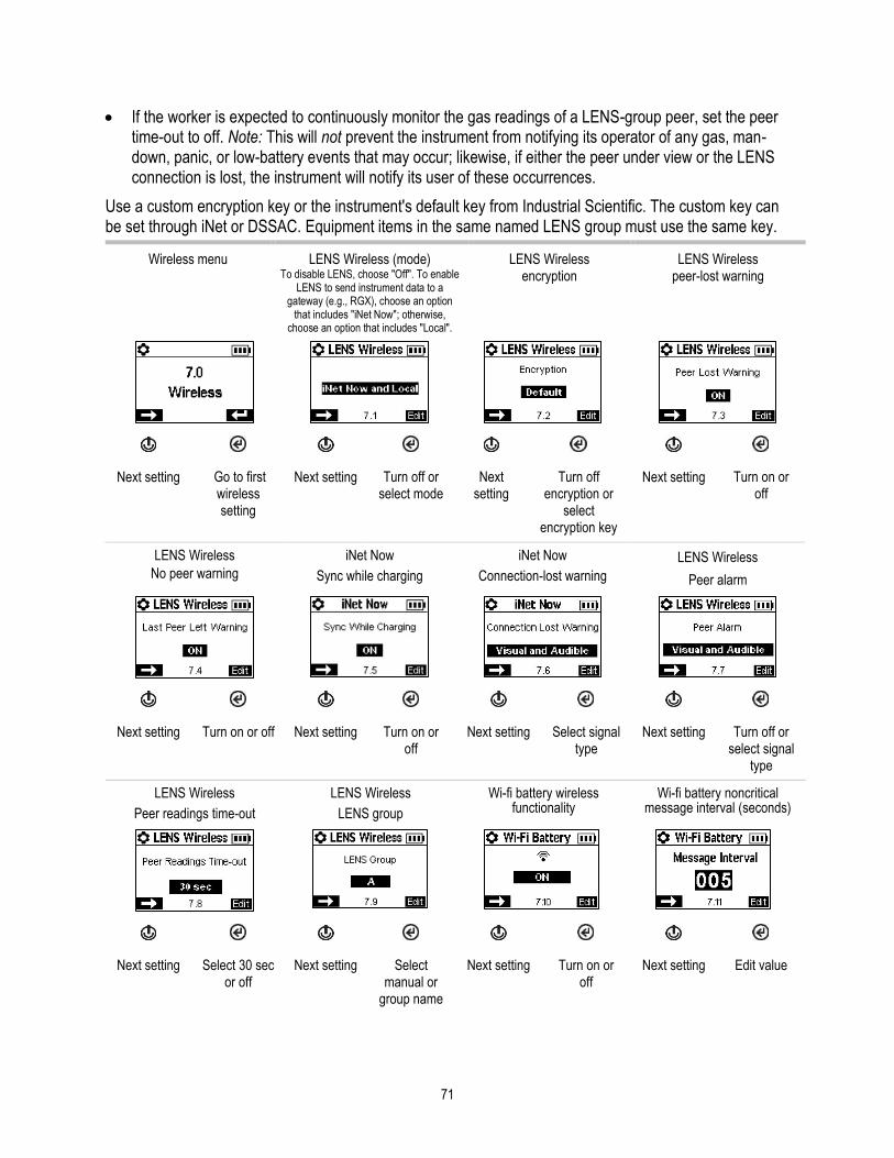
71
• If the worker is expected to continuously monitor the gas readings of a LENS-group peer, set the peer time-out to off. Note: This will not prevent the instrument from notifying its operator of any gas, man-down, panic, or low-battery events that may occur; likewise, if either the peer under view or the LENS connection is lost, the instrument will notify its user of these occurrences.
Use a custom encryption key or the instrument's default key from Industrial Scientific. The custom key can be set through iNet or DSSAC. Equipment items in the same named LENS group must use the same key.
Wireless menu LENS Wireless (mode) To disable LENS, choose "Off". To enable
LENS to send instrument data to a gateway (e.g., RGX), choose an option
that includes "iNet Now"; otherwise, choose an option that includes "Local".
LENS Wireless encryption
LENS Wireless peer-lost warning
Next setting Go to first wireless setting
Next setting Turn off or select mode
Next setting
Turn off encryption or
select encryption key
Next setting Turn on or off
LENS Wireless
No peer warning
iNet Now
Sync while charging
iNet Now
Connection-lost warning
LENS Wireless
Peer alarm
Next setting Turn on or off Next setting Turn on or off
Next setting Select signal type
Next setting Turn off or select signal
type
LENS Wireless
Peer readings time-out
LENS Wireless
LENS group
Wi-fi battery wireless functionality
Wi-fi battery noncritical message interval (seconds)
Next setting Select 30 sec or off
Next setting Select manual or
group name
Next setting Turn on or off
Next setting Edit value

72
End of menu End of settings
Revisit wireless settings
Revisit settings
Exit settings
Figure 4.2.G Navigating and editing wireless settings

5 Operation
The Instrument Buttons
The Instrument Display
Operating the Instrument
Wearing the Instrument
Using Upgrade Cards
User-Site Assignments
Using LENS Wireless
Live Monitoring
Alarms and Warnings At-a-glance
The Instrument Buttons Ventis Pro Series® instruments have three buttons, the power button, the enter button, and the panic button. During operation, the buttons are used as described below in Figure 5.1.

74
Panic
Press and hold to turn on (or off) the instrument’s panic alarm.
The panic alarm can help alert others nearby of distress. For example, the instrument operator has tripped, fallen, been otherwise injured, another person has been injured, or there is some concern about in-field circumstances.
Power
Press to view information and access utilities.
Press and hold to power on or off the instrument.
Enter
Press and hold to reset a latched alarm.
Press to start a utility.
+
To complete an instrument self-test, simultaneously press and hold, then release both buttons.
Figure 5.1 Using the buttons during operation
The Instrument Display After a unit has been powered on—its self-test and start-up sequence successfully completed—the gas readings should display. This display screen is referred to as “Home”, which will generally look like the samples shown below for a five-gas instrument (enlarged for detail) and a four-gas instrument. During operation, the home screen will display unless the instrument is using the display to provide information about an alarm, warning, indicator, or status item, or the instrument operator has accessed another option.

75
Wi-fi status LENS Wireless (peer count and group signal quality)
No fault status symbol
Home (five-gas instrument)
iNet Now status
Battery status (shown), temperature, and time
Gas name
Unit of measure
Current gas reading
Home (four-gas instrument)
Figure 5.2 Home
Operating the Instrument
From the home screen, a series of display screens may be accessible depending on the unit’s settings, and may include any or all of the options listed below.
The LENS™ Wireless peer list provides access to the following.
• The list of equipment items* in the group.
• The gas readings for any peer instrument.
• The RGX™ Gateway information screen.
• The option to leave the group.
*If a peer instrument is not assigned to a user name, its serial number or MAC address will be shown in the peer list.
The wi-fi battery display screen provides access to the following.
• The name of the connected wi-fi network.
• The option to update the wi-fi battery’s network credentials using an iAssign tag.
• GPS coordinates. The GPS lock symbol ( ) is present when the coordinates are being received via satellite; otherwise, the coordinates indicate the last-received GPS location.
• Battery firmware version number.
Other available information may include the following.
• Number of days until the instrument is due to be docked.
• Number of days until the instrument is due for calibration or the number of days since its last calibration.
• Gas-settings information (alert and alarm setpoints and calibration gas concentrations for the installed sensors).
• Assignment information (the company, user, and site assigned to the instrument).

76
Utilities give the instrument operator opportunities to complete maintenance procedures, which may include the following.
• Zero the installed sensors and optionally calibrate the instrument.
• Bump test the installed sensors.
• View and optionally clear the peak readings.
• View and optionally clear the TWA readings.
• View and optionally clear the STEL readings.
Note: When a reading is cleared, its value is reset to zero and its time-related setting is also reset to zero.
Figure 5.3 (below) describes and illustrates how to access information and utilities. Available options will vary based on instrument settings. The sample display screens shown here feature a mix of 3-, 4-, and 5-gas formats.
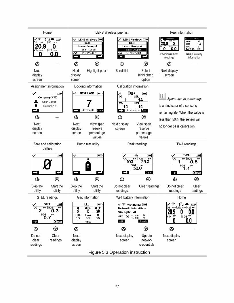
77
Home LENS Wireless peer list Peer information
Peer instrument
readings
RGX Gateway
information
— —
Next display screen
Next display screen
Highlight peer Scroll list Select highlighted
option
Next display screen
Assignment information Docking information Calibration information
Span reserve percentage
is an indicator of a sensor's
remaining life. When the value is
less than 50%, the sensor will
no longer pass calibration.
—
Next display screen
Next display screen
View span reserve
percentage values
Next display screen
View span reserve
percentage values
Zero and calibration utilities
Bump test utility Peak readings TWA readings
Skip the utility
Start the utility
Skip the utility
Start the utility
Do not clear readings
Clear readings Do not clear readings
Clear readings
STEL readings Gas information Wi-fi battery information Home
— —
Do not clear
readings
Clear readings
Next display screen
Next display screen
Update network
credentials
Next display screen
Figure 5.3 Operation instruction

78
Wearing the Instrument The instrument may be worn with its factory-installed clip, which is solely intended for attachment to a garment.
As shown below, the clip should be securely fastened and attached in a manner that ensures the instrument's sensor ports are fully exposed to the air. No part of the instrument should be covered by any garment, part of a garment, or other item that would restrict the flow of air to the sensors or impair the operator's access to the audible, visual, or vibration alarms.
Suspender clip
—
Lift the clip cover.
Position the garment between the clip's upper and lower teeth.
Press down on the clip cover to secure the clip in place.
Using Upgrade Cards
Upgrade cards can be used to add the instrument functionality needed for LENS Wireless. Simply touch the card to the front of the instrument. Then, follow the on-screen instructions and look for one of these results.
The upgrade was successful. Power off the instrument, then power it on. The feature-related symbol should now appear on the display screen; otherwise, see a supervisor.
The upgrade was not successful because the card's upgrades have all been used. Retry the upgrade with another card.
The instrument is equipped with the functionality. The instrument's related settings should be reviewed to ensure they are correct (e.g., LENS is set to "on").
iAssign Data iAssign® tags can be used to change the instrument’s user-site assignments. Each tag can contain a user name, site name, or both. It can also contain an "access level" value, which is associated with the user name. The access level is used to activate an instrument proximity alarm when the instrument enters an area where an iAssign Beacon is broadcasting an access level higher than that of the instrument’s current user assignment.
Note: An instrument’s settings may or may not permit the use of iAssign technology.
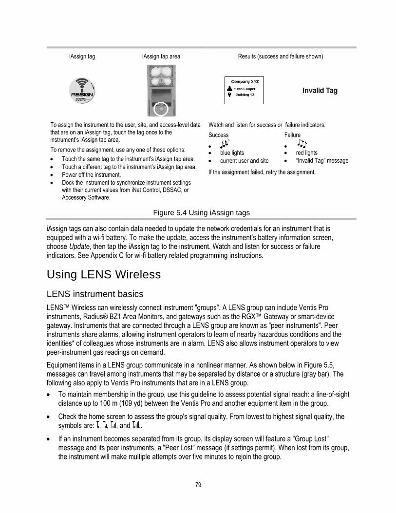
79
iAssign tag iAssign tap area Results (success and failure shown)
To assign the instrument to the user, site, and access-level data that are on an iAssign tag, touch the tag once to the instrument’s iAssign tap area.
To remove the assignment, use any one of these options:
• Touch the same tag to the instrument’s iAssign tap area.
• Touch a different tag to the instrument’s iAssign tap area.
• Power off the instrument.
• Dock the instrument to synchronize instrument settings with their current values from iNet Control, DSSAC, or Accessory Software.
Watch and listen for success or failure indicators.
Success
• • blue lights
• current user and site
Failure
• • red lights
• “Invalid Tag” message
If the assignment failed, retry the assignment.
Figure 5.4 Using iAssign tags
iAssign tags can also contain data needed to update the network credentials for an instrument that is equipped with a wi-fi battery. To make the update, access the instrument’s battery information screen, choose Update, then tap the iAssign tag to the instrument. Watch and listen for success or failure indicators. See Appendix C for wi-fi battery related programming instructions.
Using LENS Wireless
LENS instrument basics
LENS™ Wireless can wirelessly connect instrument "groups". A LENS group can include Ventis Pro instruments, Radius® BZ1 Area Monitors, and gateways such as the RGX™ Gateway or smart-device gateway. Instruments that are connected through a LENS group are known as "peer instruments". Peer instruments share alarms, allowing instrument operators to learn of nearby hazardous conditions and the identities* of colleagues whose instruments are in alarm. LENS also allows instrument operators to view peer-instrument gas readings on demand.
Equipment items in a LENS group communicate in a nonlinear manner. As shown below in Figure 5.5, messages can travel among instruments that may be separated by distance or a structure (gray bar). The following also apply to Ventis Pro instruments that are in a LENS group.
• To maintain membership in the group, use this guideline to assess potential signal reach: a line-of-sight distance up to 100 m (109 yd) between the Ventis Pro and another equipment item in the group.
• Check the home screen to assess the group's signal quality. From lowest to highest signal quality, the symbols are: , , , and ..
• If an instrument becomes separated from its group, its display screen will feature a "Group Lost" message and its peer instruments, a "Peer Lost" message (if settings permit). When lost from its group, the instrument will make multiple attempts over five minutes to rejoin the group.

80
• LENS peer-alarm signals can be turned off by pressing ; details will remain visible on the display screen.
Figure 5.5 LENS group peer-instrument locations
*Requires valid current user assignment; otherwise, the peer instrument's serial number or MAC address will display.
Joining a LENS group
When enabled for LENS Wireless, a Ventis Pro's group membership capabilities are determined by its LENS group setting of “Scan,” "Manual," or a named group (e.g., "Group A").
• With the scan setting, the instrument scans for and can join in-range LENS groups with a vacancy.
• With a manual setting, the instrument can join and leave any LENS group as needed (see Figure 5.6).
• With a named group setting, the instrument can leave its group; however, it can join another LENS group only when its LENS group setting is changed to scan, manual, or to another named group.
When an instrument in a LENS group is set to manual, and tries to join a different group, the instrument will prompt its user to confirm the change; otherwise, it will simply signal and inform its user of the joining-attempt result and indicate any required actions.
Start
Ventis Pro to Ventis Pro Ventis Pro to Radius BZ1 Ventis Pro to RGX Gateway
—
To join together Ventis Pro Series instruments, hold two instruments together—speaker to speaker—for approximately five seconds or until the instrument emits an ascending tone to indicate success.
To join a Ventis Pro Series instrument to a Radius BZ1 instrument, choose the "Join new peer" option on the Radius; this is accessible from the Wireless menu's Wireless Peer options.
Then, point the Ventis Pro IrDA window at Radius IrDA window. Hold the Ventis Pro very close to the Radius for approximately five seconds or until the Ventis Pro emits an ascending tone to indicate success.
To join a Ventis Pro Series instrument to an RGX Gateway, tap the RGX power button three times; its indicator light will flash red. Hold the Ventis Pro speaker against the RGX Gateway logo for five seconds or until the instrument emits an ascending tone to indicate success. Tap the RGX power button three times; its indicator light will change to reflect the gateway’s current state.

81
Joining in progress Leave group confirmation Home
—
The joining process requires up to 30 seconds. During that time, the Ventis Pro will periodically display its gas readings.
If the Ventis Pro is in an existing group, it will require confirmation from its user to leave that group. This allows the instrument to join the new group.
Once connected, the instrument's home screen will indicate the number of peers and group signal quality.
Figure 5.6 Join a LENS group via pairing
Leaving a LENS group
There are three ways for an instrument to intentionally leave a group without activating group-related warnings.
• The operator accesses the instrument's LENS Wireless peer list and chooses the "Leave Group" option. As shown below, if the instrument is in a named group such as Group A, the group name is indicated onscreen.
• The instrument's LENS group membership is changed, either by manually joining another group or through settings.
• The instrument LENS group setting is scan.
• The instrument is docked or powered off.
Home LENS Wireless peer list Confirmation
— —
Next display screen
Highlight menu item
Highlight Leave Goup
Enter Leave Group
Leave existing group
Stay in existing group
Figure 5.7 Leave a LENS group

82
Peer gas readings
Figure 5.8 describes how to access the gas readings of a peer instrument. The duration of the peer reading depends on the instrument setting; it may be set to time out after 30 seconds or to persist.
Home LENS Wireless peer list Peer readings
— —
Next display screen
Highlight menu item
Highlight peer name
View peer gas readings
Peer list
Figure 5.8 Access peer gas readings
Live Monitoring
iNet Now, a service of Industrial Scientific, is part of a wireless system that enables the live monitoring of gas-detection instruments. Instrument data travels wirelessly to iNet. From iNet, the safety team, using iNet Now, can learn on a live basis of in-field conditions including gas events and operator events like man-down and panic alarms.
Live monitoring requires* the following.
• Activation of the iNet Now service.
• Activation of the instrument (through iNet) for live monitoring.
• The Ventis Pro has a wireless connection to a compatible gateway, or the Ventis Pro is equipped with a wi-fi battery, or both.
*Instrument settings and connection guidelines also apply as described in this “Product Manual”.
When present on the Ventis Pro display screen, cloud and wi-fi battery symbols indicate the instrument’s live-monitoring status.
Table 5.1 Live-monitoring connection status
Cloud path Connected Not connected
Gateway only or *
Wi-fi battery only
Gateway and wi-fi battery or and —
*A connection is indicated using the solid cloud when the instrument is being monitored only by a gateway and using the cloud with bars when monitored only by a smart device. When the instrument is being monitored by both a gateway and smart-device, the solid cloud is used to indicate a connection.
Each of the compatible gateways has some unique aspects to its functionality as described below.

83
RGX Gateway
• For instrument data to reach the RGX Gateway, the Ventis Pro and the RGX must be members of the same LENS group, such as Group A, or an unnamed, ad hoc formed group.
• Counting gas-detection instruments and RGX units, the LENS group can include up to 25 equipment items. For example, if two RGX units are used to monitor Group A, the group can accommodate 23 gas-detection instruments.
Smart-device gateway
• The Ventis Pro will continually broadcast data for upload to in-range smart-devices that are running the iNet Now Sync App. The app will transmit, to iNet, data it has received from the instrument.
• The smart-device app will monitor an in-range Ventis Pro instrument regardless of the instrument's LENS group status.
• If the Ventis Pro is in a LENS group, group membership should be limited to six gas-detection instruments. Note: Unlike the RGX, the smart-device is not counted as a LENS group equipment item.
Man-down Functionality An instrument’s man-down functionality can be temporarily disabled. This can occur when the instrument’s site name is updated by an iAssign Beacon that is broadcasting a special site name. For example, a company cafeteria may have a Beacon set to this signal to temporarily prevent instruments at rest from causing man-down warnings or alarms.
The Ventis Pro display screen will feature a symbol ( ) to indicate the man-down feature is not operational. To restore functionality, simultaneously press the power and enter buttons ( and ); otherwise, the functionality will self-restore after 60 minutes or when the instrument’s site name is updated, whichever comes first.
Attaching the Alarm Silencer accessory also suspends man-down. displays on-screen when this accessory is attached. When neither symbol ( , ) is displayed, man-down is enabled.
Alarms and Warnings At-a-glance
Alarms
Alarms notify the instrument operator of danger.
The Ventis Pro Series instruments have alarms of four intensities, high, low, peer high, and peer low. Alarms are persistent. They turn off when the alarm-causing event is no longer detected, unless they are
latched. A latched alarm can be turned off by pressing . LENS peer-alarm signals can be turned off by
pressing ; details will remain visible on the display screen.
When all alarm signals* are on:
• The high alarm is bright red in color; it uses two different sounds and a vibration. It is fast-paced.
• The low alarm is similar to the high alarm but includes blue as well as bright red light. It is medium-paced.
• Peer alarms are similar to the low alarm but are slower in pace.
*Signals (visual, audible, and vibration) vary based on instrument settings.
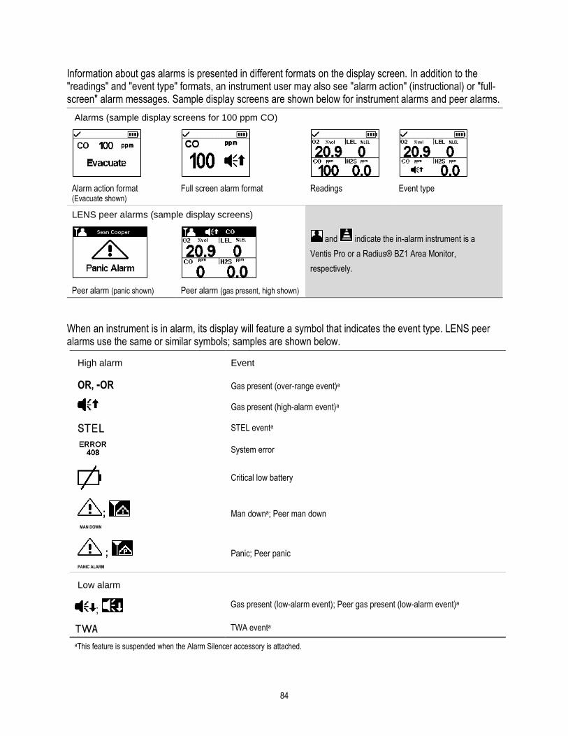
84
Information about gas alarms is presented in different formats on the display screen. In addition to the "readings" and "event type" formats, an instrument user may also see "alarm action" (instructional) or "full-screen" alarm messages. Sample display screens are shown below for instrument alarms and peer alarms.
Alarms (sample display screens for 100 ppm CO)
Alarm action format (Evacuate shown)
Full screen alarm format Readings Event type
LENS peer alarms (sample display screens)
and indicate the in-alarm instrument is a
Ventis Pro or a Radius® BZ1 Area Monitor,
respectively.
Peer alarm (panic shown) Peer alarm (gas present, high shown)
When an instrument is in alarm, its display will feature a symbol that indicates the event type. LENS peer alarms use the same or similar symbols; samples are shown below.
High alarm Event
OR, -OR Gas present (over-range event)a
Gas present (high-alarm event)a
STEL eventa
System error
Critical low battery
; MAN DOWN
Man downa; Peer man down
; PANIC ALARM
Panic; Peer panic
Low alarm
; Gas present (low-alarm event); Peer gas present (low-alarm event)a
TWA eventa
aThis feature is suspended when the Alarm Silencer accessory is attached.

85
Warnings
Warnings notify the instrument operator of a condition that needs attention.
Warnings turn on and off repeatedly. The more urgent the warning, the shorter the time between on-off occurrences: a warning that repeats every two seconds is more urgent than a warning that repeats every thirty seconds. Warnings persist until the issue is resolved; however, the signals for the iNet Now connection-lost and gas-alert warnings can be temporarily turned off by pressing ( ).
When all signals* are on, a warning appears as a short burst of red and blue light mixed with sound and vibration.
*Signals (visual, audible, and vibration) vary based on instrument settings.
Sample display screens are shown below for instrument warnings and peer warnings.
Warnings (sample display screens)
Instrument warnings
Man-down warninga Gas-present alerta Instrument issue Maintenance required Low battery
120-second pre-alarm countdown.
H2S gas-present alert. LEL sensor failure. Bump test due for CO and H2S.
Other Warnings
iAssign warning LENS Wireless warnings
Group lost Peer lost No peers
iNet Now connection lost
aThis feature is suspended when the Alarm Silencer accessory is attached.


6 Alarms, Warnings, and Notifications
Overview
Alarms
Warnings
Indicators
Failures and Errors
Overview
This chapter provides in-depth information about alarms, warnings, and notifications; portions of this text appear in abbreviated form elsewhere within this product manual.
Alarms notify the instrument operator of danger.
Warnings notify of a condition that needs attention.
Indicators notify of a status (e.g., Alarm Silencer accessory installed).
Take seriously all alarms, warnings, and indicators, and respond to each according to company policy.
Alarms
Alarms notify instrument operators of danger. Alarm intensity is based on the event type and its source. Ventis Pro instrument have alarms of four intensities; from highest to lowest they are:
• High alarm
• Low alarm
• Peer high alarm (LENS Wireless)
• Peer low alarm (LENS Wireless)
When all signals* are on, the following apply:
• The high alarm features only red light and is fast-paced.
• The low alarm is similar to the high alarm, but includes blue as well as red light. It is medium-paced.
• Peer alarms are similar to the low alarm, but are slower in pace.
*Signals (visual, audible, and vibration) vary based on instrument settings.
Alarms are persistent: they turn off when the alarm-causing event is no longer detected; however, if the instrument’s alarm latch setting is on, an alarm will remain on until the user presses to turn it off. A peer alarm can be acknowledged by pressing , which turns off alarm signals, but preserves details on the

88
display; if two or more peer alarms are active, they will all be acknowledged with a single press of the enter button .
When the instrument has more than one active alarm (or active peer alarm), the display will cycle through messages for each event; however, when the instrument is in alarm, it will not display peer alarms.
Instrument alarm events are distinguished from one another through the use of symbols (see Table 6.1) that appear on the display screen. Peer events use the same or similar symbols within peer-alarm messages.
Table 6.1 Alarm events (list)
Alarm symbol Alarm level
Alarm event Description
Instrument events
OR, -OR High Gas presenta (over-range)
The detected gas concentration is outside the sensor’s measuring range.
High Gas presenta (high-alarm)
The detected gas concentration exceeds the high-alarm setpoint.
High STELa The cumulative measure of a detected gas exceeds the STEL setpoint.
High Man downa The instrument has been stationary for the set period of time. To turn off the alarm, press and hold .
High Panic
The user has pressed the instrument’s panic button and held it long enough (approximately 3 seconds) to turn on the panic alarm. To turn off the alarm, press and hold .
High System The instrument is in failure (error code 408 shown here) and
is not operational.
High Critical low battery The instrument has shut down and is not operational.
Access Denied
High Proximity The instrument has entered an iAssign® Beacon-restricted area where the Beacon's access level is higher than that of the current user's access level.
Low Gas presenta
(low-alarm) The detected gas concentration exceeds the low-alarm setpoint.
Low TWAa The cumulative measure of detected gas exceeds the TWA
setpoint.
aThis feature is suspended when the Alarm Silencer accessory is attached.
LENS peer events
Peer high Peer gas present (high-alarm)
Peer high Peer STEL
Peer high Peer man down
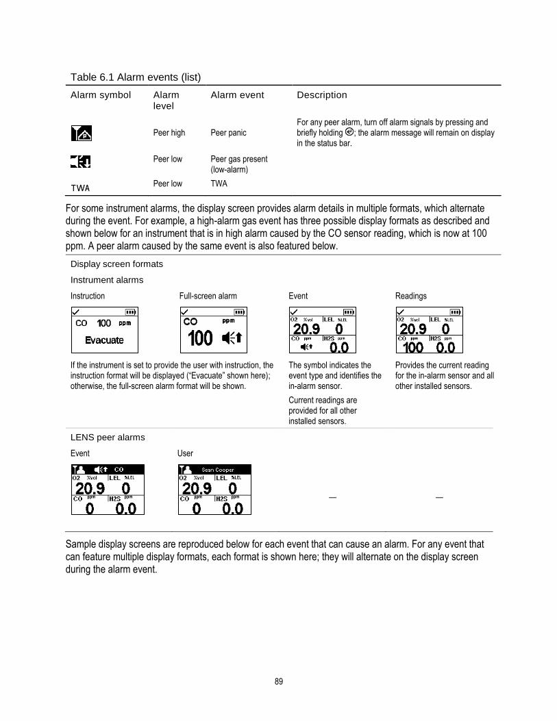
89
Table 6.1 Alarm events (list)
Alarm symbol Alarm level
Alarm event Description
Peer high Peer panic
For any peer alarm, turn off alarm signals by pressing and briefly holding ; the alarm message will remain on display in the status bar.
Peer low Peer gas present
(low-alarm)
Peer low TWA
For some instrument alarms, the display screen provides alarm details in multiple formats, which alternate during the event. For example, a high-alarm gas event has three possible display formats as described and shown below for an instrument that is in high alarm caused by the CO sensor reading, which is now at 100 ppm. A peer alarm caused by the same event is also featured below.
Display screen formats
Instrument alarms
Instruction Full-screen alarm Event Readings
If the instrument is set to provide the user with instruction, the instruction format will be displayed (“Evacuate” shown here); otherwise, the full-screen alarm format will be shown.
The symbol indicates the event type and identifies the in-alarm sensor.
Current readings are provided for all other installed sensors.
Provides the current reading for the in-alarm sensor and all other installed sensors.
LENS peer alarms
Event User
— —
Sample display screens are reproduced below for each event that can cause an alarm. For any event that can feature multiple display formats, each format is shown here; they will alternate on the display screen during the alarm event.

90
Alarm level: High
Gas present, over-range alarma
—
Gas present, high alarma
STEL alarma
—
Critical low battery alarm
System alarm Man-down alarma Panic alarm
Alarm level: Low
Gas present, low alarma
TWA alarma
—
aThis feature is suspended when the Alarm Silencer accessory is attached.

91
Alarm level: LENS peer high
Peer gas present, high alarm
Peer STEL Peer panic alarm Peer man down
Alarm level: LENS peer low
Peer gas present, low alarm
Peer TWA
— —
Figure 6.1 Alarm events (display screens)
Warnings Warnings turn on and off repeatedly. The more urgent the warning, the shorter the time between on-off occurrences: a warning that repeats every two seconds is more urgent than a warning that repeats every thirty seconds.
Warnings persist until the event is resolved; however, the iNet Now connection-lost warning and the gas-alert warning signal can be temporarily turned off by pressing the enter button . In some cases, an unresolved warning will cause an alarm. For example, if the man-down warning turns on and the instrument operator does not turn it off, the instrument and its signals will change from warning status to alarm status. Similarly, a low-battery warning that is not resolved will change to alarm status indicating a critical low-battery condition.
When all signal* settings are on, warnings appear as a short burst of blue and red light mixed with sound and a vibration.
As with alarm events, warnings are distinguished from one another on the instrument display (see Table 6.2 below).
For LENS-group peer instruments, when an instrument can no longer connect with any instrument in its group, it is said to be "lost"—not within range of any peer-instrument. These warnings will occur:
• The instrument will activate its "group lost" warning to indicate to its operator that he or she is no longer connected to the group. It will continually attempt to rejoin the group for five minutes.
• The peer instruments will activate the "peer lost" warning, which will identify the name** of the lost peer, the instrument user who has lost his or her connection to the group.
*Signals (visual, audible, and vibration) vary based on instrument settings.
**Requires valid user assignment.

92
Table 6.2 Warnings (list)
Symbol Warning Description
MAN DOWN
Man-downa The instrument has not moved for the set period of time. To turn off the warning, move the instrument.
Gas alerta A detected gas concentration may be approaching alarm levels.
To turn off the warning, press and hold .
LEL-Low O2 LEL and O2 sensors are installed and the concentration of O2 is
insufficient for LEL sensor functionality.
F Sensor failure One or more sensors is not working.
Instrument maintenance required (bump test shown)
The instrument is in need of some form of maintenance (calibration, bump test, etc.).
Low battery The instrument’s battery is low; replace or charge the battery.
blinking iNet Now connection lost The instrument's data is either not reaching the gateway or the
gateway-to-iNet data upload is not occurring, so instrument data are not available to the users and message recipients of iNet Now. The instrument's iNet Now connection-lost warning turns on. Press to acknowledge the warning and temporarily turn off the warning signals.
not blinking iNet Now connection lost warning acknowledged
The instrument's iNet Now connection-lost warning was user acknowledged; however, the connection remains lost. Instrument data are not available to the users and message recipients of iNet Now.
Peer Name Peer lost A peer instrument has become disconnected from the LENS
group without using the "Leave Group" option.
Group Lost Group lost The user has not used the "Leave Group" option, but has
become disconnected from the LENS group; the instrument may be out of range from all other instruments in the group.
;
NO PEERS NO PEERS
No peers All equipment items have left the group
aThis feature is suspended when the Alarm Silencer accessory is attached.
Display-screen reproductions are shown below for each condition that can cause a warning. For any warning that features multiple display formats, each format is shown; they will alternate on the display screen during the event.

93
Man-down warninga
(120 second countdown to alarm shown here)
Gas alerta
(5.0 ppm H2S shown here)
Sensor failure warning
(LEL shown here)
Maintenance required warnings Low battery warning
(Calibration due for CO and H2s)
(Dock overdue; manual calibration required for CH4 High)
Other Warnings
LENS Wireless warnings
iAssign warning Group lost Peer lost No peers
NO PEERS
iNet Now connection lost
— — — —
Figure 6.2 Warnings (display screens)
aThis feature is suspended when the Alarm Silencer accessory is attached.

94
Indicators Most indicators turn on once, then off; only the confidence indicator persists, repeating every 90 seconds. If all signal* settings are on, indicators will look and sound like this:
Indicator Status Color Sound
iAssign update, calibration, or bump test Success Blue
iAssign update, calibration, or bump test Failure Red
Alarm Silencer accessory Installed Blue
Confidence indicator Instrument on Blue Beep
*Signals (visual, audible, and vibration) vary based on instrument settings.
Failures and Errors Some failures and errors are easily resolved by qualified personnel (see Table 6.3 below). For other errors or failures, contact Industrial Scientific for assistance.
Table 6.3 Failures and errors
The sample display screen (left) indicates a sensor failure. The position of the “F” means it is the LEL sensor that is in failure. As noted below, different abbreviations or symbols are used to indicate other failures and errors.
Symbols Cause Recommended actions
F only The sensor is in a general state of failure and is not operational.
Power off the instrument, then power it back on. If the failure persists, check the sensor for proper installation.
ERR The sensor is installed in the wrong location.
Install the sensor in its correct location.
The sensor failed the zero process.
Repeat the zero process.
BUMP and F The sensor failed bump testing.
Calibrate the instrument, then complete a bump test.
CAL and F The sensor failed calibration.
Calibration results indicate the sensor’s span reserve percentages. When that value is less than 50%, the sensor will not pass calibration and is due for replacement. If the span reserve percentage indicates the sensor is greater than 50% check for the following possible causes for the failure.
• Ensure the calibration cup is compatible with the instrument and is correctly and securely placed on the instrument.
• Check the tubing for splits, blockages, or damage.
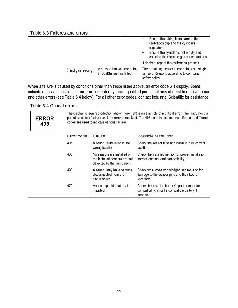
95
Table 6.3 Failures and errors
• Ensure the tubing is secured to the calibration cup and the cylinder's regulator.
• Ensure the cylinder is not empty and contains the required gas concentrations.
If desired, repeat the calibration process.
! and gas reading A sensor that was operating in DualSense has failed.
The remaining sensor is operating as a single sensor. Respond according to company safety policy.
When a failure is caused by conditions other than those listed above, an error code will display. Some indicate a possible installation error or compatibility issue; qualified personnel may attempt to resolve these and other errors (see Table 6.4 below). For all other error codes, contact Industrial Scientific for assistance.
Table 6.4 Critical errors
The display screen reproduction shown here (left) is an example of a critical error. The instrument is put into a state of failure until the error is resolved. The 408 code indicates a specific issue; different codes are used to indicate various failures.
Error code Cause Possible resolution
406 A sensor is installed in the wrong location.
Check the sensor type and install it in its correct location.
408
No sensors are installed or the installed sensors are not detected by the instrument.
Check the installed sensor for proper installation, correct location, and compatibility.
490
A sensor may have become disconnected from the circuit board.
Check for a loose or dislodged sensor, and for damage to the sensor pins and their board receptors.
470
An incompatible battery is installed.
Check the installed battery’s part number for compatibility; install a compatible battery if needed.


7 Maintenance
Guidelines
Process At-a-glance
Supplies and Preparation
Instruction
Guidelines This chapter provides instruction for manually completing these utilities: bump testing, zeroing, and calibration. These procedures can also be completed using compatible Industrial Scientific docking stations and accessories that are supported by iNet, DSSAC, or Accessory Software. Elsewhere in this product manual (Chapter 1), are the definitions and recommended practices for each procedure.
Use these guidelines to prepare for manually completing a zero, calibration, or bump test.
• Work in an area known to be nonhazardous.
• Use certified Industrial Scientific calibration gas.
• Choose calibration gas cylinders that are suitable for the installed sensors and their calibration gas settings, and for the instrument's process-type setting ("quick" vs. "standard").
When instruments are set to the "quick" process type, one application of gas is permitted. This setting is usually the choice for applications in which one calibration gas cylinder contains all the required gases.
When set to the "standard" process type, it is often because more than one gas cylinder is required to calibrate or bump test all the installed sensor types. For example, a cylinder that contains more than one gas may be suitable for three of the installed sensors while the fourth sensor may require a gas that is not contained in that cylinder. During the standard process, the instrument will prompt its user for the application of each gas and, between gases, will allow time for a change of cylinders.
Process At-a-glance
Whether bump testing or calibrating manually, the basic steps are:
• Gather the needed supplies.
• Prepare the gas cylinder for use.
• Access the utility on the instrument.
• Connect the calibration cup to the instrument.
• Turn on the gas cylinder.
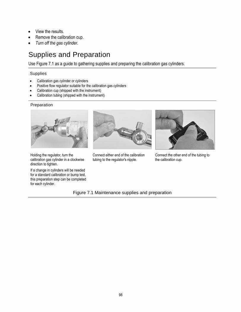
98
• View the results.
• Remove the calibration cup.
• Turn off the gas cylinder.
Supplies and Preparation Use Figure 7.1 as a guide to gathering supplies and preparing the calibration gas cylinders.
Supplies
• Calibration gas cylinder or cylinders
• Positive flow regulator suitable for the calibration gas cylinders
• Calibration cup (shipped with the instrument)
• Calibration tubing (shipped with the instrument)
Preparation
Holding the regulator, turn the calibration gas cylinder in a clockwise direction to tighten.
If a change in cylinders will be needed for a standard calibration or bump test, this preparation step can be completed for each cylinder.
Connect either end of the calibration tubing to the regulator's nipple.
Connect the other end of the tubing to the calibration cup.
Figure 7.1 Maintenance supplies and preparation
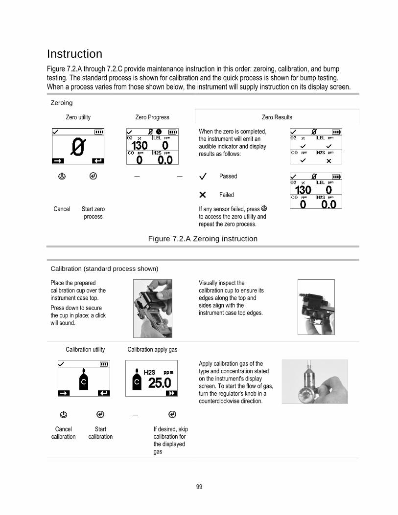
99
Instruction Figure 7.2.A through 7.2.C provide maintenance instruction in this order: zeroing, calibration, and bump testing. The standard process is shown for calibration and the quick process is shown for bump testing. When a process varies from those shown below, the instrument will supply instruction on its display screen.
Zeroing
Zero utility Zero Progress Zero Results
When the zero is completed, the instrument will emit an audible indicator and display results as follows:
— — Passed
Failed
Cancel Start zero process
If any sensor failed, press to access the zero utility and repeat the zero process.
Figure 7.2.A Zeroing instruction
Calibration (standard process shown)
Place the prepared calibration cup over the instrument case top.
Press down to secure the cup in place; a click will sound.
Visually inspect the calibration cup to ensure its edges along the top and sides align with the instrument case top edges.
Calibration utility Calibration apply gas
Apply calibration gas of the type and concentration stated on the instrument's display screen. To start the flow of gas, turn the regulator's knob in a counterclockwise direction.
—
Cancel calibration
Start calibration
If desired, skip calibration for the displayed gas

100
Calibration progress Calibration results
When the calibration is completed, the instrument will display a calibration results of passed or failed, along with the sensor's span reserve percentage.
— Passed The span reserve percentage is an indicator of the sensor's remaining life. When that value is less than 50%, the sensor will no longer pass calibration.
Cancel calibration
Failed
After the first sensor is calibrated and the results displayed, the instrument will activate the calibration process for the next gas
type starting with the "Apply gas" request. The instrument will wait a few minutes to receive the requested calibration gas. This is
the opportunity to change cylinders if needed, then continue the calibration process (in the same manner as descirbed above for
H2S) until all calibration gases have been applied.
After the installed sensors have been calibrated (or skipped), the instrument's display screen will state the calibration results for
all installed sensors.
All-sensor calibration results End
Passed
Failed
►► Skipped
─ Not relevant to the procedure.
Remove the calibration cup: lift up from the cup's tabs.
Stop the flow of gas: turn the regulator knob in a clockwise direction and tighten.
Use Table 7.1 as a guide to help determine the probable cause for calibration failure and find recommendations for resolution.
Figure 7.2.B Calibration instruction

101
Bump testing (quick process shown)
Place the prepared calibration cup over the instrument case top.
Press down to secure the cup in place; a click will sound.
Visually inspect the calibration cup to ensure its edges along the top and sides align with the instrument case top edges.
Bump test utility Apply gas Bump test progress
Apply calibration gases of the type and concentration stated on the instrument's display screen: turn the cylinder's regulator knob in a counterclockwise direction.
—
Cancel bump test
Start bump test
Cancel bump test
All-sensor bump test results End
After the bump test is completed, summary results are shown.
If any sensors fail the bump test, the calibration required warning will turn on. Complete a calibration for any failed sensor, then repeat the bump test.
Remove the calibration cup: lift up from the cup's tabs.
Stop the flow of gas: turn the regulator knob in a clockwise direction and tighten.
Passed
Failed
►► Skipped
─ Not relevant to the procedure
Figure 7.2.C Bump testing instruction

102
Table 7.1 Calibration failure: possible causes and recommendations
Possible causes for calibration failure
Recommendations
The sensor's span reserve percentage is less than 50%.
The sensor is due for replacement.
The gas cylinder did not contain the calibration gas in the concentration needed.
Repeat the calibration with a suitable gas cylinder.
When all sensors fail, this may indicate the calibration gas did not reach the sensors.
Check for the following.
• Ensure the calibration cup is compatible with the instrument.
• Ensure the calibration cup is correctly and securely placed on the instrument.
• Check the tubing for splits, blockages, or damage.
• Ensure the tubing is secured to the calibration cup and the cylinder's regulator.
• Ensure the cylinder is not empty and contains the required gas concentrations.
• Be sure the cylinder is turned on when the apply-gas screen displays and remains on until the calibration is completed.
Repeat the calibration.

8 Service and Warranty
Service
Warranty
Service
Guidelines
Service tasks that can be completed by Industrial Scientific customers are described in this Product Manual. Table 8.1 indicates which parts and components are customer replaceable. All other service tasks should be performed only by Industrial Scientific or an authorized service center.
• Service tasks should be performed only by qualified personnel.
• Use only approved Industrial Scientific parts and accessories.
• Perform service tasks in a nonhazardous location.
• Work on a nonconductive surface in a well-lit area.
• Wear grounding straps to prevent electrostatic discharge (ESD), which can cause damage to the instrument's electronics.
• Be sure to turn off the instrument before (1) servicing the unit or (2) replacing the battery.
• Before removing the instrument’s battery, dock the instrument to synchronize it with iNet Control, Accessory Software, or DSSAC.
Use care when working with the adhesive-backed filters and gaskets.
• Be careful not to pierce or tear these items.
• When using tweezers, apply gentle pressure.
• Once the adhesive touches a surface, any attempt to remove or reposition the item may cause it damage.
Use care when working with sensors and water barriers.
• Do not touch the sensors' membranes as this can contaminate the items.
• Do not separate the sensor from its membrane.
• Do not damage or tear the membranes or water barriers.
Supplies ✓ T10 torx screwdriver ✓ Needle-nose tweezers (for barrier and filter replacement)

104
Instruction
Figures 8.1 and 8.2 provide disassembled views of the instrument and its pump module, respectively, identifying their parts and components. Use Table 8.1 to determine which items are customer replaceable and identify their part names and part numbers.
Figure 8.1 Instrument diagram

105
Figure 8.2 Pump module diagram

106
Table 8.1 Instrument and pump module parts list
Diagram number
Part name Customer replaceable
Part number Notes
Instrument
1 Dust barrier kit Yes 18109613 Includes ten speaker dust barriers.
2 (includes 1 and 3)
Case top assembly Yes 17156049-XY Assembly includes case top, speaker dust barrier, and sensor water barriers.
X indicates case-cover color, where 0 = Black and 1 = Orange.
Y indicates name plate, where 1 = Ventis Pro4 and 2 = Ventis Pro5.
3 Sensor water barrier kit Yes 18109436 Includes one water barrier for each sensor port.
4, 4a, and 5 See "Table 2.7 Sensor specifications" for details about sensor compatibility and permitted installation locations.
Ammonia (NH3) Yes 17155306-6 Ventis Pro5 only.
Carbon Dioxide/LEL (Propane), IR (CO2/LEL)
Yes 17155304-U Ventis Pro5 only.
Carbon Dioxide/Methane (CO2/CH4)
Yes 17155304-V Ventis Pro5 only.
Carbon Monoxide (CO) Yes 17155306-1
Carbon Monoxide/Hydrogen Sulfide (CO/H2S)
Yes 17155304-J Ventis Pro5 only.
Carbon Monoxide/Hydrogen Sulfide (CO/H2S)
Yes 17155306-J Ventis Pro5 only.
Carbon Monoxide with low Hydrogen cross-sensitivity (CO/H2 Low)
Yes 17155306-G —
Chlorine (Cl2) Yes 17155306-7 Ventis Pro5 only.
Hydrocarbon, IR (Propane)
Yes 17155304-P —
Hydrogen Cyanide (HCN)
Yes 17155306-B —
Hydrogen Sulfide (H2S) Yes 17155306-2 —
Hydrogen Sulfide (H2S) Yes 17155304-2 —
LEL (Methane) Yes 17155304-L —
LEL (Pentane) Yes 17155304-K —
Methane, 0-5% vol. Yes 17155304-M —
Methane, IR, (CH4) Yes 17155304-N —

107
Table 8.1 Instrument and pump module parts list
Diagram number
Part name Customer replaceable
Part number Notes
Nitrogen Dioxide (NO2) Yes 17155306-4 —
Oxygen (O2) Yes 17155304-3 —
Oxygen, Long-life (O2) Yes 17155304-Y —
Oxygen, Long-life (O2) Yes 17155306-Y —
Phosphine (PH3) Yes 17155306-9 —
Sulfur Dioxide (SO2) Yes 17155306-5 —
6 LCD assembly No* — —
7 Audible alarm speaker No* — —
8 Vibration alarm motor Yes 17120080 —
9 Case bottom No* — Screw torque: .39 newton m (55 ounce-force inch)
Rechargeable Lithium-ion batteries
19 Ventis Pro Wi-fi Battery Yes
See Table 8.2 Screw torque: 0.39 newton m (55 ounce-force inch)
10 Ventis Standard Battery Yes
11 Ventis Slim Extended Battery
Yes
12 Ventis Extended Run-time Battery
Yes
13 Battery cover (for use with Ventis Extended Run-time battery)
Yes
14 Suspender clip Yes 17120528 —
15 Screw with locking washer
Yes 17158205 Torque: .88 newton m (125 ounce-force inch)
16 Suspender clip spacer Yes 17152506 Use with deep-dimension batteries (e.g., wi-fi battery)
17 Locking washer Yes 17153137 —
18 Screw (for use with suspender clip spacer)
Yes 17158281 Torque: .88 newton m (125 ounce-force inch)
Pump
1P - 6P Pump module Yes VPP-ABCD A indicates battery, where 0 = no battery and 2 = extended range rechargeable lithium-ion battery
B indicates color, where 0 = black and 1 = orange
C indicates approvals, where 1=UL and CSA, 2 = ATEX and IECEx, 3 = MSHA, and 9=INMETRO

108
Table 8.1 Instrument and pump module parts list
Diagram number
Part name Customer replaceable
Part number Notes
D indicates language, where 1 = English, 2 = French, 3 = Spanish, 4 = German, C=Chinese, and -7 = Brazilian Portuguese
Pump module parts
1P Ventis Extended Run-time Battery
Yes See Table 8.2 Screw torque: 0.39 newton m (55 ounce-force inch)
2P (includes 3P)
Door assembly Yes 17156945-X
X indicates color, where 0 = black and 1 = orange.
3P Gaskets No* — —
4P Internal filter
Yes 17058157 —
5P Inlet cap Yes 17129909 —
*For items that are not customer replaceable, contact Industrial Scientific or an authorized service center.
Battery parts
The base part number that appears on the label of a Ventis battery item uses an eight-digit numeric format (XXXXXXXX). The corresponding orderable part numbers use the four-letter base reference "VTSB", which is followed by a three-character suffix. The first suffix character is a number that designates the battery type; the second and third are used to indicate color and approval options, respectively. For example, as shown below in Table 8.2, a rechargeable slim extended lithium-ion battery kit that is black and has a UL approval would have an orderable part number of VTSB-401 and its label would state a part number of 17157350-01.
Table 8.2 Battery parts list
Diagram number
Rechargeable Lithium-ion batteries
Part numbers Optionsa (X and Y)
Label Orderable kit
19 Ventis Pro Wi-fi Battery 17159022-XY VTSB-AXY
X indicates color: 0 for black; 1 for
orange (battery cover only)
Y indicates approvals: 1 for UL,
CSA, ATEX, and IECEx; 2 for MSHA; 3 for China EX; 4 for ANZEx; and 5
for INMETRO
10 Ventis Standard Battery 17134453-XY VTSB-1XY
11 Ventis Slim Extended Battery
17157350-XY VTSB-4XY
12 and 13 Ventis Extended Run-time Battery (includes battery and cover)
17148313-Y (battery)
17151184-XY (cover)
VTSB-2XY (kit)b
aColor and approval options may vary for each battery item. For more information, contact Industrial Scientific or an authorized distributor of its products.
bThe battery and cover may be ordered separately using these part numbers 17148313-Y (battery) 17151184-XY (cover).

109
Power off the instrument before disassembling it or performing any service task.
Pump installation
Unscrew and remove the belt clip. Store the clip, screw, and washer for future use.
Unscrew, lift, and remove the battery from the diffusion instrument; store it for future use.
Loosen the pump door screw. Slide the pump door down; lift it to open.
Install a compatible extended range battery—label side up—into the lower receptacle of the pump case.
Place the instrument in the pump case; tighten the four torx screws on the back of the pump.
Lower the pump door. Slide it into its fully closed, clicked-shut position.
Tighten the pump door screw.
Pump door replacement
—
Loosen the pump door screw.
Slide the pump door down; lift it to open.
The door is hinged to the pump module with two pegs that slide into grooves. Angle the door so that one peg moves to the bottom of its groove and the other moves the top of its groove. Lift the door to remove it.
Install the new door in the same manner the door was removed.
— —
Lower the pump door. Slide it into its fully closed, clicked-shut position. Tighten the pump door screw.

110
Pump cap and internal filter replacement
Important – Power off the instrument prior to performing this service task.
To unscrew and remove the pump cap, turn it in a counterclockwise direction.
Remove the internal filter from the inlet barrel.
Tip: If the filter does not drop out when you remove the cap, gently tap the side of the instrument.
Insert the replacement filter in the filter cap (filter P/N 17058157 shown).
Invert the instrument. Place the new internal filter in the inlet barrel of the instrument.
Inspect the inlet barrel and sealing O-ring in the instrument and filter cap. Ensure that inlet barrel is clean and that both O-rings are in place and free of damage.
Inspect the filter cap inlet and inlet barrel for dirt, debris or liquid. Remove any dirt, debris, or liquid by blowing air through the cap or wiping gently with a clean, lint-free cloth.
Note: Never operate the pump without the internal filter.
Secure the pump cap to the inlet barrel: turn the cap in a clockwise direction to tighten.
WARNING: Explosion hazard. Only replace batteries in nonhazardous locations.
Battery replacement
Using a torx screwdriver, loosen all four screws from the battery (left) or the battery cover (right).
Lift the battery (left) or battery cover and battery (right) away from the instrument.
Note: If the instrument is without a battery for more than 40 minutes, the instrument date and time settings will be deleted. The next time the instrument is powered on, it will prompt its operator to set the date and time to support data-log integrity; this can be done manually or by docking the instrument.
To install a two-item battery, first place the battery in the battery cover. When placed correctly, the battery's label will show.
Next, align the battery cover with the instrument.
To install a single-part battery, align it with the instrument.
Using a torx screwdriver, tighten each of the four screws to secure the battery (shown) or battery cover to the instrument.
Refer to Table 8.1 for torque value.

111
Clip replacement
Clip only (use with standard and slim extended batteries)
—
Lift the clip's cover. To remove the clip, use a torx screwdriver to access the clip's screw. Turn counterclockwise to loosen the screw.
Remove the screw, washer, and clip; set aside or store for future use.
To attach the clip, put the washer onto the screw and place the screw in the clip's middle hole.
Turn the screw clockwise to tighten; refer to Table 8.1 for torque value.
Clip with spacer (use with deep-dimension batteries)
—
To remove the clip, use a torx screwdriver to access the clip's screw. Turn counterclockwise to loosen the screw.
Remove the washer, screw, clip, and spacer; set aside or store for future use.
To attach the clip and spacer, cover the case bottom's platform with the spacer.
Put the washer onto the screw and place the screw in the clip's middle hole.
Guide the screw into the spacer's hole and into the instrument case bottom.
Turn clockwise to tighten; refer to Table 8.1 for torque value.
Speaker dust barrier replacement
Using a finger or needle-nose tweezers, peel off the dust barrier and discard.
Place the barrier sheet on the work surface.
Scrape lightly across the paper to the barrier's edge. Gently lift to expose a portion of its adhesive back. Peel the barrier from the sheet.
Guide the new barrier—adhesive side down—onto the case top.
Press and hold to support adhesion.
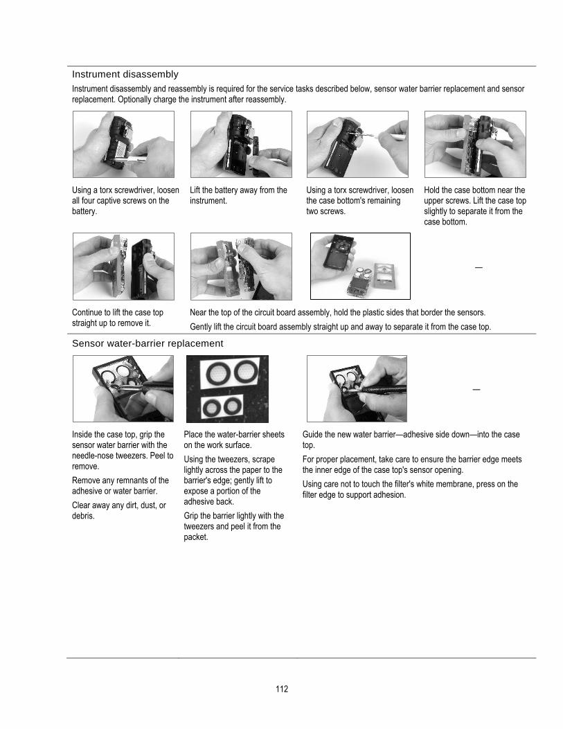
112
Instrument disassembly
Instrument disassembly and reassembly is required for the service tasks described below, sensor water barrier replacement and sensor replacement. Optionally charge the instrument after reassembly.
Using a torx screwdriver, loosen all four captive screws on the battery.
Lift the battery away from the instrument.
Using a torx screwdriver, loosen the case bottom's remaining two screws.
Hold the case bottom near the upper screws. Lift the case top slightly to separate it from the case bottom.
—
Continue to lift the case top straight up to remove it.
Near the top of the circuit board assembly, hold the plastic sides that border the sensors.
Gently lift the circuit board assembly straight up and away to separate it from the case top.
Sensor water-barrier replacement
—
Inside the case top, grip the sensor water barrier with the needle-nose tweezers. Peel to remove.
Remove any remnants of the adhesive or water barrier.
Clear away any dirt, dust, or debris.
Place the water-barrier sheets on the work surface.
Using the tweezers, scrape lightly across the paper to the barrier's edge; gently lift to expose a portion of the adhesive back.
Grip the barrier lightly with the tweezers and peel it from the packet.
Guide the new water barrier—adhesive side down—into the case top.
For proper placement, take care to ensure the barrier edge meets the inner edge of the case top's sensor opening.
Using care not to touch the filter's white membrane, press on the filter edge to support adhesion.
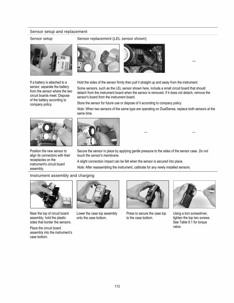
113
Sensor setup and replacement
Sensor setup Sensor replacement (LEL sensor shown)
—
If a battery is attached to a sensor, separate the battery from the sensor where the two circuit boards meet. Dispose of the battery according to company policy.
Hold the sides of the sensor firmly then pull it straight up and away from the instrument.
Some sensors, such as the LEL sensor shown here, include a small circuit board that should detach from the instrument board when the sensor is removed. If it does not detach, remove the sensor's board from the instrument board.
Store the sensor for future use or dispose of it according to company policy.
Note: When two sensors of the same type are operating on DualSense, replace both sensors at the same time.
— —
Position the new sensor to align its connectors with their receptacles on the instrument's circuit board assembly.
Secure the sensor in place by applying gentle pressure to the sides of the sensor case. Do not touch the sensor's membrane.
A slight connection impact can be felt when the sensor is secured into place.
Note: After reassembling the instrument, calibrate for any newly installed sensors.
Instrument assembly and charging
Near the top of circuit board assembly, hold the plastic sides that border the sensors.
Place the circuit board assembly into the instrument’s case bottom.
Lower the case top assembly onto the case bottom.
Press to secure the case top to the case bottom.
Using a torx screwdriver, tighten the top two screws. See Table 8.1 for torque value.

114
Charging
Rear insert position
Forward insert position
Place the battery against the case bottom.
Using a torx screwdriver, tighten the screws. See Table 8.1 for torque value.
If the charger includes an insert, adjust the insert to ensure the battery contacts touch the charging contacts. Once the insert is placed into the desired position, a firm push down will secure it in place.
To prevent loss of the insert, keep it in the cradle in its most-used position.
Insert position: forward
Insert side: 1
Lithium-ion battery Slim extended lithium-ion battery
Extended range lithium-ion battery (aspirated shown).
Also use this position for any diffusion instrument—deep-dimension battery combination.
Insert position: forward
Insert side: 1
Insert position: forward
Insert side: 2
Insert position: rear
Insert side: 1
NOTE: Do NOT touch the charger's battery contacts as contaminants and damage will inhibit charging.
Figure 8.3 Service Tasks

115
Warranty Industrial Scientific Corporation’s Ventis® Pro Series portable gas monitors are warranted to be free from defects in material and workmanship under normal and proper use and service for as long as the instrument is supported by Industrial Scientific (excludes sensors, batteries, filters, and pumps). O2, LEL, CO (excluding COSH or CO/H2 Low), and H2S sensors are warranted for three years from date of shipment. All other sensors, pumps, filters and battery packs are warranted for two years from date of shipment, except where otherwise stated in writing in the literature accompanying the product.
Limitation of Liability
THE WARRANTY SET FORTH ABOVE IS STRICTLY LIMITED TO ITS TERMS AND IS IN LIEU OF ALL OTHER WARRANTIES, GUARANTEES, EXPRESS OR IMPLIED, ARISING BY OPERATION OF LAW, COURSE OF DEALING, USAGE OF TRADE OR OTHERWISE. INDUSTRIAL SCIENTIFIC MAKES NO OTHER WARRANTIES, EITHER EXPRESSED OR IMPLIED, INCLUDING BUT NOT LIMITED TO THE WARRANTIES OF MERCHANTABILITY OR FITNESS FOR PARTICULAR PURPOSE.
SHOULD THE PRODUCT FAIL TO CONFORM TO THE ABOVE WARRANTY, BUYER’S ONLY REMEDY AND INDUSTRIAL SCIENTIFIC’S ONLY OBLIGATION SHALL BE, AT INDUSTRIAL SCIENTIFIC’S SOLE OPTION, REPLACEMENT OR REPAIR OF SUCH NON-CONFORMING GOODS OR REFUND OF THE ORIGINAL PURCHASE PRICE OF THE NONCONFORMING GOODS.
IN NO EVENT WILL INDUSTRIAL SCIENTIFIC BE LIABLE FOR ANY OTHER SPECIAL, INCIDENTAL, CONSEQUENTIAL, PUNITIVE OR OTHER SIMILAR DAMAGES, INCLUDING LOSS OF PROFIT OR LOSS OF USE, ARISING OUT OF THE SALE, MANUFACTURE OR USE OF ANY PRODUCTS SOLD HEREUNDER WHETHER SUCH CLAIM IS PLEADED IN CONTRACT OR IN TORT, INCLUDING STRICT LIABILITY IN TORT AND WHETHER INDUSTRIAL SCIENTIFIC HAS BEEN ADVISED OF THE POTENTIAL FOR SUCH DAMAGES. Industrial Scientific’s total liability hereunder from any cause whatsoever (except liability from personal injury caused by Industrial Scientific’s negligence), whether arising under contract, warranty, tort (including negligence), strict liability, products liability or any other theory of liability, will be limited to the lesser of Buyer’s actual damages or the price paid to Industrial Scientific for the Products that are the subject of Buyer’s claim. All claims against Industrial Scientific must be brought within one year after the cause of action arises, and Buyer expressly waives any longer statute of limitations.
It shall be an express condition to Industrial Scientific’s warranty that all products be carefully inspected for damage by Buyer upon receipt, be properly calibrated for Buyer’s particular use, and be used, repaired, and maintained in strict accordance with the instructions set forth in Industrial Scientific’s product literature. Repair or maintenance by non-qualified personnel will invalidate the warranty, as will the use of non-approved consumables or spare parts. As with any other sophisticated product, it is essential and a condition of Industrial Scientific’s warranty that all personnel using the products be fully acquainted with their use, capabilities and limitations as set forth in the applicable product literature.
Buyer acknowledges that it alone has determined the intended purpose and suitability of the goods purchased. It is expressly agreed by the parties that any technical or other advice given by Industrial Scientific with respect to the use of the goods or services is given without charge and at Buyer’s risk; therefore, Industrial Scientific assumes no obligations or liability for the advice given or results obtained.

Appendix A
Supplemental Information about Gases and Sensors
Toxic Gases
A sensor is designed to detect for and measure the presence of a particular gas, the "target gas"; however, it may also respond to other gases. When this is the case, the sensor is said to have "cross-sensitivity" to another gas, which will interfere with the target-gas readings. Table A.1 provides insight to the levels of cross sensitivity that can exist and whether a nontarget gas will have the effect of adding to or subtracting from the target-gas readings.
For example, a site is being monitored for H2S; the air also contains NO2. According to table A.1, the H2S sensor will respond to NO2, so the H2S readings will account for both gases. Because the NO2 cross-sensitivity value is negative (-25%), its presence will subtract from the H2S readings, which will generate an H2S reading that is lower than the actual concentration of H2S contained in the air sample.
When a cross-sensitivity value is positive, the opposite will happen. When a gas has a positive cross-sensitivity value, it will add to a sensor's target gas reading, which will generate a reading that is higher than the actual concentration of the target gas contained in the air sample.
Table A.1 Cross-sensitivity guidelines (%)
Sensor
Target Gas CO CO/H2 Low H2S SO2 NO2 HCN NH3
CO 100 100 1 1 0 0 0
H2S 5 5 100 1 -40 10 25
SO2 0 5 5 100 0 — -40
NO2 -5 5 -25 -165 100 -70 -10
Cl2 -10 0 -20 -25 10 -20 -50
ClO2 — — — — — — —
HCN 15 — — 50 1 100 5
HCl 3 — — 5 0 0 0
PH3 — — — — — 425 —
NO 25 40 -0.2 1 5 -5 0
H2 22 3 0.08 0.5 0 0 0
NH3 0 0 0 0 0 0 100
The values supplied above are estimates. They generally apply only to new sensors used for monitoring gases in these environmental conditions: 20 °C (68 °F), 50% RH, and 1 atm. Values are subject to change.
“—” indicates no available data.

117
Combustible Gases
Tables A.2 and A.3 provide the LEL for select combustible gases as they apply to specific sensors. These tables also provide correlation factors that can help determine the percentage LEL when the actual gas differs from the gas that was used to calibrate the instrument.
For example, if the instrument reads 10% LEL in a pentane atmosphere, and was calibrated to methane, the actual percentage LEL is determined as follows:
1. Locate the table cell where the sample gas (pentane) intersects with the calibration gas (methane).
2. Multiply the cell's value (2.02) by the unit's LEL reading (10%) to calculate the actual concentration of 20.2% LEL.
Table A.2 LEL correlation factors for the sensors 17155304-K, -L, and -M
Sample gas
LEL
(% vol)
Calibration gas
Butane Hexane Hy-drogen
Methane Pentane Propane
Acetone 2.5% 1.00 0.70 1.70 1.70 0.90 1.10
Acetylene 2.5% 0.70 0.60 1.30 1.30 0.70 0.80
Benzene 1.2% 1.10 0.80 1.90 1.90 1.00 1.20
Butane 1.9% 1.00 0.58 1.78 1.67 0.83 1.03
Ethane 3.0% 0.80 0.60 1.30 1.30 0.70 0.80
Ethanol 3.3% 0.89 0.52 1.59 1.49 0.74 0.92
Ethylene 2.7% 0.80 0.60 1.40 1.30 0.70 0.90
Hexane 1.1% 1.71 1.00 3.04 2.86 1.42 1.77
Hydrogen 4.0% 0.56 0.33 1.00 0.94 0.47 0.58
Isopropanol 2.0% 1.10 0.90 2.00 1.90 1.00 1.20
Methane 5.0% 0.60 0.35 1.06 1.00 0.50 0.62
Methanol 6.0% 0.60 0.50 1.10 1.10 0.60 0.70
Nonane 0.8% 2.22 1.30 3.95 3.71 1.84 2.29
Pentane 1.4% 1.21 0.71 2.15 2.02 1.00 1.25
Propane 2.1% 0.97 0.57 1.72 1.62 0.80 1.00
Styrene 0.9% 1.30 1.00 2.20 2.20 1.10 1.40
Toluene 1.1% 1.53 0.89 2.71 2.55 1.26 1.57
Xylene 1.1% 1.50 1.10 2.60 2.50 1.30 1.60
JP-4 — — — — — 1.20 —
JP-5 — — — — — 0.90 —
JP-8 — — — — — 1.50 —

118
Table A.3 LEL correlation factorsa for the sensor 17155304-U
Calibration gas
Sample gas
LEL
(% vol)
Propane
Acetone 2.5 3.28
Butane 1.9 0.97
Chloromethane 8.1 0.966
Cyclopentane 1.1 1.62
Dichloroethane 5.4 8.57
Ethane 3.0 1.01
Ethanol 3.5 1.65
Ethyl Acetate 2.0 1.69
Ethylene 2.7 3.43
Ethylene Oxide 3.0 0.845
Hexane 1.1 0.8
Isopropanol 2.0 1.43
Methane 5.0 3
Methanol 6.0 2.22
Methyl ethyl ketone 1.4 1.87
Pentane 1.4 0.89
Propylene 2.4 1.69
Toluene 1.1 1.18
Xylene 1.1 1.51
aThese factors only apply to gas concentrations expressed in % volume terms and up to 2.5%vol. These factors may vary from sensor to sensor with tolerance of ± 25% deviation.
Note: LEL correlation-factor accuracy may change without notice and is impacted by exposure to sensor inhibitors or poisons, sensor aging, the gas-detection applications and environment, and other factors. Calibrate instruments using the intended target gas when feasible and validate correlation factors as needed.

119
Appendix B
How to program a wi-fi battery-equipped Ventis Pro
1. On your cell phone, download the iAssign® App from Google Play.
2. Open the app; go to “Tag Management” and select “Write Tag”.
3. Go to the Wi-fi Battery tab to program the iAssign tag with your network ID, password, and security type.
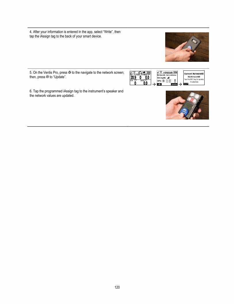
120
4. After your information is entered in the app, select “Write”, then tap the iAssign tag to the back of your smart device.
5. On the Ventis Pro, press to the navigate to the network screen; then, press to “Update”.
→ →
6. Tap the programmed iAssign tag to the instrument’s speaker and the network values are updated.

121
Appendix C
Marking Requirements ATEX Markings Industrial Scientific Corp. 15205 USA VENTIS Pro SERIES DEMKO 15 ATEX 1571 Ex da ia IIC T4 Ga Ex db ia IIC T4 Gb with IR sensor installed Ex da ia I Ma Ex db ia I Ma with IR sensor installed -40°C 1 Ta 1 +50°C -20°C 1 Ta 1 +50°C with IR sensor installed IP 64 Aspirated Configuration Use only replaceable battery pack P/N 17148313-1. Do Not Recharge or Replace battery in Hazardous Locations. Charging contact parameters: Um = 6.2V [Serial Number] [Month/Year of Production] Diffusion Configuration Use only replaceable battery pack P/N 17148313-1, 17157350-X1, 17159022-X1, or 17134453-X1 Do Not Recharge or Replace battery in Hazardous Locations. Charging contact parameters: Um = 6.2V [Serial Number] [Month/Year of Production]
IECEx Markings Industrial Scientific Corp. 15205 USA VENTIS PRO SERIES IECEx UL15.0114 Ex da ia IIC T4 Ga Ex db ia IIC T4 Gb with IR sensor installed -40°C 1 Ta 1 +50°C -20°C 1 Ta 1 +50°C with IR sensor installed -20°C 1 Ta 1 +50°C IP 64 Aspirated Configuration Use only replaceable battery pack P/N 17148313-1. Do Not Recharge or Replace battery in Hazardous Locations. Charging contact parameters: Um = 6.2V [Serial Number] [Month/Year of Production] Diffusion Configuration Use only replaceable battery pack P/N 17148313-1, 17157350-X1, 17159022-X1, or 17134453-X1 Do Not Recharge or Replace battery in Hazardous Locations. Charging contact parameters: Um = 6.2V [Serial Number] [Month/Year of Production]

Contact Information
Industrial Scientific Corporation 1 Life Way Pittsburgh, PA 15205-7500 USA Web: www.indsci.com Phone: +1 412-788-4353 or 1-800-DETECTS (338-3287) E-mail: [email protected] Fax: +1 412-788-8353
Industrial Scientific France S.A.S. 11D Rue Willy Brandt 62002 Arras Cedex, France Web: www.indsci.com Téléphone : +33 (0)1 57 32 92 61 E-mail: [email protected] Fax: +33 (0)1 57 32 92 67
英思科传感仪器(上海)有限公司
地址:中国上海市浦东金桥出口加工区桂桥路290号
邮编:201206
电话:+86 21 5899 3279
传真:+86 21 5899 3280
E-mail:[email protected]
网址: www.indsci.com
服务热线:+86 400 820 2515 To locate a nearby distributor of our products or an Industrial Scientific service center or business office, visit us at www.indsci.com. Rendez-vous sur notre site Web www.indsci.com, si vous voulez trouver un distributeur de nos produits près de chez vous, ou, si vous recherchez un centre de service ou un bureau Industrial Scientific. Besuchen Sie uns unter www.indsci.com, um einen Vertriebshändler unserer Produkte oder ein Servicecenter bzw. eine Niederlassung von Industrial Scientific zu finden. Para buscar un distribuidor local de nuestros productos o un centro de servicio u oficina comercial de Industrial Scientific, visite www.indsci.com.
如需查找就近的产品经销商或 Industrial Scientific 服务中心或业
务办事处,请访问我们的网站 www.indsci.com。