Product Manual - Chart Industries · 2020. 3. 26. · Product Manual - VS/HS Storage Systems 1...
38
Part Number 14084612, Rev. D © 2015 Chart Inc. Product Manual VS and HS Storage Systems For Models: • VS-525/900/1500 • VS-3000/6000 • VS-9000/11000/13000/15000 • HS-1500 • HS-3000/6000 • HS-9000/11000/13000/15000 Designed and Built by: Chart Inc. 407 7th Street NW New Prague, MN 56071 USA (800) 400-4683
Transcript of Product Manual - Chart Industries · 2020. 3. 26. · Product Manual - VS/HS Storage Systems 1...

Part Number 14084612, Rev. D© 2015 Chart Inc.
Product ManualVS and HS Storage Systems
For Models:• VS-525/900/1500• VS-3000/6000• VS-9000/11000/13000/15000
• HS-1500• HS-3000/6000• HS-9000/11000/13000/15000
Designed and Built by:
Chart Inc.407 7th Street NW New Prague, MN 56071 USA (800) 400-4683


iiiProduct Manual - VS/HS Storage Systems
ContentsRevision Log iv
Preface . . . . . . . . . . . . . . . . . . . . . . . . . . . . . . . . . . . . . . . . . . . . . . . . . . . . .1General 1
VS/HS-Series Product Advantages 1Product Manual 1Terms 2Acronyms / Abbreviations 2
Safety . . . . . . . . . . . . . . . . . . . . . . . . . . . . . . . . . . . . . . . . . . . . . . . . . . . . .3General 3Safety Bulletin 3Oxygen Deficient Atmospheres 3Oxygen Cleaning 4Oxygen Enriched Atmospheres 4Nitrogen and Argon 5
Introduction . . . . . . . . . . . . . . . . . . . . . . . . . . . . . . . . . . . . . . . . . . . . . . . . . .7General 7Features 7Physical Description 7Safety Devices 8Operational Systems 8Filling General 8Pressure Transfer Filling 8Pump Transfer 9Gas Withdrawal 9Pressure Building & Economizer 10Liquid Withdrawal 10Liquid Withdrawal (for pumping) 11
Installation . . . . . . . . . . . . . . . . . . . . . . . . . . . . . . . . . . . . . . . . . . . . . . . . . . 13General 13Handling Instructions 13Rigging Details 13Unloading 13Cargo Container 13Inspection 14Receiving Checkpoints 14Vacuum Test Procedure 14Site Considerations 14Site Preparation 15Site Protection 15Other Site Considerations 15Removing and Transporting Tank 15
Disconnecting the System 15Transporting 15
VS-Series Weights Table 17HS-Series Weights Table 17Liquid Level Gauge Valve Procedures 18
Liquid Level Gauge with a Needle Valve for Equalization 18Liquid Level Gauge with a 5-Way Equalization Valve 18Liquid Level Gauge with a 4-Way Equalization Valve 19

iv Table of Contents Product Manual - VS/HS Storage Systems
Operations . . . . . . . . . . . . . . . . . . . . . . . . . . . . . . . . . . . . . . . . . . . . . . . . . . 21Purging and Fill Considerations 21Tank Purging Procedure 21Initial (Warm Tank) Filling Procedure 22Preparing The Station For Operation 22Tank Pressure Control 22
Increasing Tank Pressure 23Decreasing Tank Pressure 23
Refilling 23Tank Refilling Procedure 23Gas Withdrawal Procedure 24Liquid Withdrawal 24Liquid Withdrawal Procedure 24
Maintenance . . . . . . . . . . . . . . . . . . . . . . . . . . . . . . . . . . . . . . . . . . . . . . . . . 25General 25Compatibility and Cleaning 25Periodic Inspection 25
Periodic Inspection Intervals 25Brazing 25Maintenance Checks and Adjustments 25
Vacuum Integrity Check 25Normal Evaporation Rate (NER) Test 26Pressure and Liquid Level Gauge Checks and Adjustments 26
Troubleshooting 26Repair 28Valve Repair 28Tank Burst Disc (PSE-1) Repair 28Tank Safety Relief Valve (PSV-1) 28Testing After Repair 28Returning Defective Components 29
Specifications . . . . . . . . . . . . . . . . . . . . . . . . . . . . . . . . . . . . . . . . . . . . . . . . 31Component Function Table 32Liquid Level Charts 34O&D Drawings (unit specific) 34P&ID Drawings (unit specific) 34
Revision LogRevision Level Date Description
A 07/13/2011 Add section 7.1.5 and remove section 7.10.B 05/07/2014 Update and reformatC 11/25/2014 Add note to Pressure Building section of IntroductionD 11/23/2015 Add Valve Procedure information to Installation section.

1Product Manual - VS/HS Storage Systems
GeneralChart’s VS & HS-Series Storage Systems, are offered in a wide range of sizes for applications requiring MAWP of 175 and 250 psig (12 and 17 bar) as standard.
Our proprietary composite insulation system gives you the competitive edge with high thermal performance, extended hold times resulting in low life-cycle costs. In addition, the light weight design reduces installation costs.
The VS & HS-Series Storage Systems are backed by an industry leading five-year vacuum warranty. They have piping modules designed for ease-of-access to all operational control valves with stainless steel interconnecting piping for improved durability. Combination pressure building /economizer regulator for each pressure adjustment and extended bonnet bronze control valves for ease of operation.
VS/HS-Series Product Advantages
• Sizes, pressures and configurations to meet most applications
• Leg design provides better access to anchor bolts
• Plumbing built in accordance with ASME B31.3 code and leak tested at 1.1 times the MAWP
• Long-life Hentzen urethane paint system
• Chart’s innovative modular piping system provides an Industry Standard Piping Configuration
– Reduces your life-cycle by reducing the number of external piping joints, minimizing the risk of external piping leaks and the cost to repair
– Simple by design yet robust and able to support a broad range of customer applications
• High performance safety system with dual relief valves and rupture disks supplied as a standard
• New, innovative vertical fin pressure building system improves performance, while reducing frost and ice build-up to further reduce your maintenance costs
• Interchangeable gauge systems with digital telemetry capable gauge and flexible stainless steel interconnection lines
Product ManualThe VS/HS Storage System Product Manual is designed to be used in conjunction with all vertical and horizontal cryogenic storage tanks provided by Chart. This manual contains information regarding the safe operation and handling of liquid nitrogen, argon, and oxygen with the tank. It should be thoroughly read and understood by anyone that operates the equipment. This manual is intended to provide the user with all the necessary information needed to install, operate and maintain a VS/HS Storage System. If there are any questions regarding the operation of the tank, contact Chart’s Technical Service division at 1-800-400-4683.
The schematics, piping illustrations, and parts lists on the drawings show a reference number for each component used on the tank. The reference numbers may refer to the same functional component between the various models. The reference numbers will be used throughout this manual to draw specific attention to a component while describing its function, operation, or repair.
The safety requirements for operating the tank and handling or transporting extremely cold liquid products are shown in the Safety section. Use this safety section as a “Safety Check-List” each time the equipment is being used.
The Introduction section discusses the general features of the tank and the theory of operation.
In the Installation section there are illustrations for how to uncrate and install the tank.
For information on how to operate the tank refer to the Operations section.
The Maintenance and Specifications sections describe the specific tank models covered by this manual. They contain general information, technical specifications, plumbing schematics, and parts list. They should be reviewed first and referred to as the rest of the manual is read.
Preface

2 Preface Product Manual - VS/HS Storage Systems
TermsThroughout this manual safety precautions will be designated as follows:
Warning! Description of a condition that can result in personal injury or death.
Caution! Description of a condition that can result in equipment or component damage.
Note: A statement that contains information that is important enough to emphasize or repeat.
Acronyms / AbbreviationsThe following acronyms / abbreviations may be used throughout this manual:
ASME American Society of Mechanical Engineers
BAR Pressure (Metric)
CGA Compressed Gas Association
DOT Department of Transportation
Kg/cm2 Kilogram-force per square centimeter
MAWP Maximum Allowable Working Pressure
NER Normal Evaporation Rate
NFPA National Fire Protection Association
Nm3/hr Normal Cubic Meter per hour
PB Pressure Builder
PN Part Number
PSF Pounds per Square Foot
PSI Pounds per Square Inch
PSIG Pounds per Square Inch (Gauge)
SCF Standard Cubic Feet
SCM Standard Cubic Meters

3Product Manual - VS/HS Storage Systems
GeneralThe VS/HS storage tank consists of an inner pressure vessel encased within an outer carbon steel vacuum shell. The container operates under low-to-medium pressure, but is protected from over pressurization by use of a rupture disc and a safety relief valve Safety relief devices are used to protect the pressure vessel and vacuum casing, sized and selected in accordance with ASME and other standards to include a dual relief valve and rupture disc system to protect the pressure vessel, and a reverse buckling rupture disc or lift plate to protect the vacuum casing (outer vessel). The tanks are designed and engineered for safe, reliable operations, and will provide many years of trouble-free operation. Strict compliance with proper safety and handling practices is necessary when using a tank. We recommend that all our customers re-emphasize safety and safe handling practices to all their employees and customers. While every possible safety feature has been designed into the units and safe operations are anticipated, it is essential that every user of the tanks carefully read all warnings and cautions listed in this safety section and contained in the manual itself. Also read the information provided in the safety bulletins for oxygen and inert gases. Periodic review of this safety summary is recommended
Safety BulletinPortions of the following information have been extracted from Safety Bulletin SB-2 from the Compressed Gas Association, Inc. Additional information on oxygen, nitrogen, argon, and cryogenics is available from the CGA.
Cryogenic containers, stationary or portable, are from time to time subjected to assorted environmental conditions of an unforeseen nature. This safety bulletin is intended to call attention to the fact that whenever a cryogenic container is involved in any incident whereby the container or its safety devices are damaged, good safety practices must be followed. The same holds true whenever the integrity or function of a container is suspected of abnormal operation.
Good safety practices dictate the contents of a damaged or suspect container be carefully emptied as soon as possible. Under no circumstances should a damaged container be left with product in it for an extended period of time. Further, a damaged or suspect container should not be refilled unless the unit has been repaired and re-certified.
Incidents which require that such practices be followed include: highway accidents, immersion of a container in water, exposure to extreme heat or fire, and exposure to most adverse weather conditions (earthquake, tornadoes, etc.).
As a rule of thumb, whenever a container is suspected of abnormal operation, or has sustained actual damage, good safety practices must be followed.
In the event of known or suspected container vacuum problems (even if an extraordinary circumstance such as those noted above has not occurred), do not continue to use the unit. Continued use of a cryogenic container that has a vacuum problem can lead to embrittlement and cracking. Further, the carbon steel jacket could possibly rupture if the unit is exposed to inordinate stress conditions caused by an internal liquid leak.
Prior to reusing a damaged container, the unit must be tested, evaluated, and repaired as necessary. It is highly recommended that any damaged container be returned to Chart for repair and re-certification.
The remainder of this safety bulletin addresses those adverse environments that may be encountered when a cryogenic container has been severely damaged. These are oxygen deficient atmospheres, oxygen enriched atmospheres, and exposure to inert gases.
Caution! Before locating oxygen equipment, become familiar with the NFPA standard No. 55 “Compressed Gases and Cryogenic Fluids Code” and with all local safety codes.
Oxygen Deficient AtmospheresWarning! Nitrogen and argon vapors in air
may dilute the concentration of oxygen necessary to support or sustain life. Exposure to such an oxygen deficient atmosphere can lead to unconsciousness and serious injury, including death.
The normal oxygen content of air is approximately 21%. Depletion of oxygen content in air, either by combustion or by displacement with inert gas, is a potential hazard and users should exercise suitable precautions.
One aspect of this possible hazard is the response of humans when exposed to an atmosphere containing only 8-12%
Safety

4 Safety Product Manual - VS/HS Storage Systems
oxygen. In this environment, unconsciousness can be immediate with virtually no warning.
When the oxygen content of air is reduced to about 15-16%, the flame of ordinary combustible materials, including those commonly used as fuel for heat or light, may be extinguished. Somewhat below this concentration, an individual breathing the air is mentally incapable of diagnosing the situation because the onset of symptoms such as sleepiness, fatigue, lassitude, loss of coordination, errors in judgment and confusion can be masked by a state of “euphoria,” leaving the victim with a false sense of security and well being.
Human exposure to atmosphere containing 12% or less oxygen leads to rapid unconsciousness. Unconsciousness can occur so rapidly that the user is rendered essentially helpless. This can occur if the condition is reached by an immediate change of environment, or through the gradual depletion of oxygen
Most individuals working in or around oxygen deficient atmospheres rely on the “buddy system” for protection - obviously the “buddy” is equally susceptible to asphyxiation if he or she enters the area to assist the unconscious partner unless equipped with a portable air supply. Best protection is obtained by equipping all individuals with a portable supply of respirable air. Life lines are acceptable only if the area is essentially free of obstructions and individuals can assist one another without constraint.
If an oxygen deficient atmosphere is suspected or known to exist:
1 Use the “buddy system.” Use more than one “buddy” if necessary to move a fellow worker in an emergency.
2 Both the worker and “buddy” should be equipped with self-contained or airline breathing equipment.
Oxygen CleaningWhen replacing components, only use parts which are considered compatible with liquid oxygen and have been properly cleaned for oxygen service (Refer to CGA Bulletin G-4.1 “Equipment Cleaned for Oxygen Service”). Do not use regulators, fittings, or hoses which were previously used in a compressed air environment on these tanks. Only oxygen compatible sealants or Teflon tape should be used on threaded fittings. All new piping joints should be leak tested with an oxygen compatible leak-test solution.
Oxygen Enriched AtmospheresAn oxygen-enriched atmosphere occurs whenever the normal oxygen content of air is allowed to rise above 23%. While oxygen is nonflammable, ignition of combustible materials can occur more readily in an oxygen-rich atmosphere than in air; and combustion proceeds at a faster rate although no more heat is released.
It is important to locate an oxygen system in a well ventilated location since oxygen-rich atmospheres may collect temporarily in confined areas during the functioning of a safety relief device or leakage from the system.
Oxygen system components, including but not limited to, containers, valves, valve seats, lubricants, fittings, gaskets and interconnecting equipment including hoses, shall have adequate compatibility with oxygen under the conditions of temperature and pressure to which the components may be exposed in the containment and use of oxygen. Easily ignitable materials shall be avoided unless they are parts of equipment or systems that are approved, listed, or proven suitable by tests or by past experience.
Compatibility involves both combustibility and ease of ignition. Materials that burn in air may burn violently in pure oxygen at normal pressure, and explosively in pressurized oxygen. In addition, many materials that do not burn in air may do so in pure oxygen, particularly when under pressure. Metals for containers and piping must be carefully selected, depending on service conditions. The various steels are acceptable for many applications, but some service conditions may call for other materials (usually copper or its alloy) because of their greater resistance to ignition and lower rate of combustion.
Similarly, materials that can be ignited in air have lower ignition energies in oxygen. Many such materials may be ignited by friction at a valve seat or stem packing, or by adiabatic compression produced when oxygen at high pressure is rapidly introduced into a system initially at low pressure.
Warning! If clothing should be splashed with liquid oxygen it will become highly flammable and easily ignited while concentrated oxygen remains. Such clothing must be aired out immediately, removing the clothing if possible, and should not be considered safe for at least 30 minutes.

5SafetyProduct Manual - VS/HS Storage Systems
Nitrogen and ArgonNitrogen and argon (inert gases) are simple asphyxiates. Neither gas will support or sustain life and can produce immediate hazardous conditions through the displacement of oxygen. Under high pressure these gases may produce narcosis even though an adequate oxygen supply sufficient for life is present.
Nitrogen and argon vapors in air dilute the concentration of oxygen necessary to support or sustain life. Inhalation of high concentrations of these gases can cause anoxia, resulting in dizziness, nausea, vomiting, or unconsciousness and possibly death. Individuals should be prohibited from entering areas where the oxygen content is below 19% unless equipped with a self-contained breathing apparatus. Unconsciousness and death may occur with virtually no warning if the oxygen concentration is below approximately 8%. Contact with cold nitrogen or argon gas or liquid can cause cryogenic (extreme low temperature) burns and freeze body tissue
Persons suffering from lack of oxygen should be immediately moved to areas with normal atmospheres. SELF-CONTAINED BREATHING APPARATUS MAY BE REQUIRED TO PREVENT ASPHYXIATION OF RESCUE WORKERS. Assisted respiration and supplemental oxygen should be given if the victim is not breathing. If cryogenic liquid or cold boil-off gas contacts worker’s skin or eyes, the affected tissue should be flooded or soaked with tepid water (105-115ºF or 41-46ºC). DO NOT USE HOT WATER. Cryogenic burns that result in blistering or deeper tissue freezing should be examined promptly by a physician.

7Product Manual - VS/HS Storage Systems
GeneralThe VS/HS storage tanks are compact and self-contained cryogenic systems designed for the economical storage of liquid nitrogen, oxygen, or argon with the ability to provide it to the application as either liquid or gas.
The Chart model designation for a particular tank can be found on the tank data plate and its associated paper work. The model designation is broken down as Model (VS), Capacity (3000), Inner Material (S), Insulation Type (C), MAWP (175).
Note: Refer to the Maintenance and Specifications sections of this manual to see the specific model specification, charts, schematics, and parts covered by the contents of this manual.
FeaturesThe tanks are designed to provide a convenient, reliable and economical method for the storage and delivery of liquid oxygen, nitrogen and argon. Important features of these containers include:
• Long-term hold time due to highly efficient multi-layer insulation systems
• A pressure building system that can be used to increase working pressure during high withdrawal operations.
• An economizer system that lowers tank pressure during normal operations to prevent the loss of product through the relief valve.
• A top and bottom fill line that allows the tank to be refilled from a liquid supply unit by either pumping or pressure transfer.
• Simple and convenient piping controls to reduce the number of fittings and components. The control valves are modular units. The fill module has top, bottom and pressure control isolation valves. The pressure control regulator acts as the pressure builder and economizer with a built-in isolation valve. The vent module has a dual safety valve and manual vent valve
• Auxiliary liquid and gas use
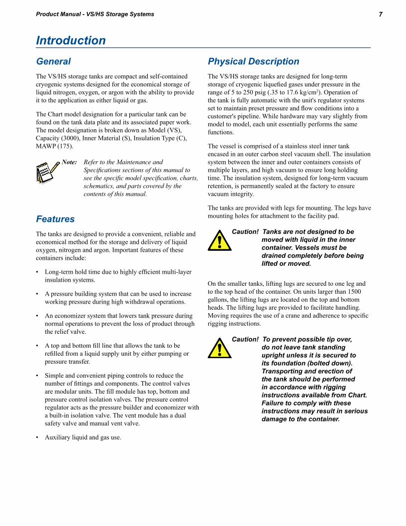
Physical DescriptionThe VS/HS storage tanks are designed for long-term storage of cryogenic liquefied gases under pressure in the range of 5 to 250 psig (.35 to 17.6 kg/cm2). Operation of the tank is fully automatic with the unit's regulator systems set to maintain preset pressure and flow conditions into a customer's pipeline. While hardware may vary slightly from model to model, each unit essentially performs the same functions
The vessel is comprised of a stainless steel inner tank encased in an outer carbon steel vacuum shell. The insulation system between the inner and outer containers consists of multiple layers, and high vacuum to ensure long holding time. The insulation system, designed for long-term vacuum retention, is permanently sealed at the factory to ensure vacuum integrity
The tanks are provided with legs for mounting. The legs have mounting holes for attachment to the facility pad.
Caution! Tanks are not designed to be moved with liquid in the inner container. Vessels must be drained completely before being lifted or moved.
On the smaller tanks, lifting lugs are secured to one leg and to the top head of the container. On units larger than 1500 gallons, the lifting lugs are located on the top and bottom heads. The lifting lugs are provided to facilitate handling. Moving requires the use of a crane and adherence to specific rigging instructions
Caution! To prevent possible tip over, do not leave tank standing upright unless it is secured to its foundation (bolted down). Transporting and erection of the tank should be performed in accordance with rigging instructions available from Chart. Failure to comply with these instructions may result in serious damage to the container.
Introduction

8 Introduction Product Manual - VS/HS Storage Systems
Safety DevicesThe vessels are protected from over-pressurization with a tank pressure relief device. The normal relief device pressure setting is at the operating pressure of the inner vessel. Other relief valve pressure settings are available as long as they are not greater than the operating pressure of the inner vessel.
Each container is further protected from over-pressurization by a secondary rupture disc assembly. This bursting disc will rupture to completely relieve inner tank pressure in the event the tank relief valve fails and pressure exceeds the rupture disc setting
Caution! The vacuum space is protected from over-pressurization by use of a tank annular space lift plate assembly.
Note: Safety devices meet all of the requirements of CGA Pamphlet S-1.2 Safety Relief Device Standards, Part 2, Cargo and Portable Tanks for Compressed Gases.
Operational SystemsThe tank has the ability to be filled with a cryogenic product, build pressure inside the vessel, and deliver either liquid or gas for a specific application.
The following section will discuss the theory behind these operations. The illustrations show a vertically configured tank.
All operations are done with the control valves located on the underside of the tank. The valves are labeled for easy identification.
The schematic, illustrations, and component function table in the Specifications section show how the plumbing circuitry operates for the specific model of tank. It is important that the operators be familiar with the plumbing control valves.
Filling GeneralThe following recommendations should be used to optimize tank filling:
1 Keep the transfer lines as short as possible. Long non-insulated transfer lines will result in higher fill losses and longer fill times.
2 Anytime liquid can be entrapped in a line between two valves, the line must be equipped with a safety relief device
3 Conduct the filling operation in as short a time as possible.
The vessel should be visually inspected before every fill for possible damage, cleanliness, and suitability for its intended gas service. If damage is detected (i.e., serious dents, loose fittings, etc) repair the unit as soon as possible.
All tanks are shipped with NF grade gaseous nitrogen to prevent moisture from entering the tank. For this reason the tank should be thoroughly purged with the applicable gas prior to filling.
When filling the unit with cryogenic liquid, the transfer may be made with a centrifugal pump or through a pressure transfer operation.
Pressure Transfer FillingLiquid will always flow from a vessel of higher pressure to one with low pressure. This method is commonly used to fill a small tank by connecting a transfer line between the delivery source and the top fill valve (HCV-2) of the tank.
Liquid may be transferred into the tank so that venting is not necessary. The top fill valve (HCV-2) on the tank has a spray header that will splash the incoming cold liquid onto the somewhat warmer gas in the tank. The cold liquid will actually collapse the vessel pressure while being sprayed into the warmer gas. The bottom fill valve allows liquid to be transferred into the tank at a fast rate. The tank pressure can be maintained at a constant pressure level (PI-1) by opening the bottom fill valve (HCV-1) completely and throttling open the top fill valve to lower and maintain a constant pressure. The full trycock valve (HCV-4) spits liquid when the vessel becomes full

9IntroductionProduct Manual - VS/HS Storage Systems
If the pressure in the receiving tank is higher than the transport, blow down of the pressure in the receiving tank may be required via HCV-12
Since there are many variables in pressure transfer deliveries, it is also possible to connect a transfer line between the delivery source and the bottom fill valve (HCV-1) of the tank. The transfer takes place as the vent valve (HVC-12) of the tank is opened. This allows gas to escape and lowers the pressure in the receiving tank. The full trycock valve (HCV-4) spits liquid when the vessel becomes full.
Note: PB inlet (HCV-3) and PB outlet ((HCV-11) must remain fully open during fill operation.
Pump TransferThe pump transfer method is the most commonly used to fill the tank. Top and bottom filling lowers the product losses associated with filling. Liquid may be pumped into the tank so that venting is not necessary. The top fill valve (HCV-2) has a spray header that will splash the incoming cold liquid onto the somewhat warmer gas in the tank. The cold liquid will actually collapse the vessel pressure while being sprayed into the warmer gas. The bottom fill valve allows liquid to be pumped into the tank at a fast rate. The tank pressure can be maintained at a constant pressure level (PI-1) by opening the bottom fill valve (HCV-1) completely and throttling open the top fill valve to lower and maintain a constant pressure. The full trycock valve (HCV-4) spits liquid when the vessel becomes full
Gas WithdrawalWhen a tank is used for gas withdrawal, the normal operating pressure range is controlled by the pressure settings of both the pressure building and economizer function of the pressure control valve (PCV-1). The economizer regulator is set approximately 7-8 psi (1.0 kg/cm2) higher than the pressure building portion of the pressure control valve (PCV-1).
When the supply of gaseous product is the primary operation of the tank, external vaporizers and an additional regulator must be added after the gas use valve (HCV-13) to step down the pressure to the gas application. This regulator (PCV-5) is found in the final line option provided by Chart.

10 Introduction Product Manual - VS/HS Storage Systems
Pressure Building & Economizer
When the operating pressure of the tank is above the economizer setting, the regulator will open and the gas that is being supplied to the application will be pulled out of the vapor space in the top of the tank (A). It will travel through the pressure control valve (PCV-1) and then back into the tank where it connects to the gas use line (K) before it reaches the final line valve (HCV-13). The action of removing gas from the tank reduces the tank's pressure.
When the operating pressure is reduced to the economizer setting, the pressure control valve (PCV-1) will close. Gas is still required by the application and will pull liquid up the dip tube (D) and into the gas use line (see Figure D). It will then go through an external vaporizer that turns the liquid into gas and warms it before it is delivered to the final line regulator. The pressure decay will be much slower since a small amount of liquid can be vaporized into a large amount of gas
When the pressure falls below the pressure building setting, the pressure control valve (PCV-1) will open for pressure building. This will allow liquid from the bottom of the tank to run into the pressure builder vaporizer (PB-1). The liquid will turn into gas and be delivered back into the top vapor space of the tank (A). The result of this operation is a rise in pressure in the tank.
Note: Upon tank installation, the nuts mounting the PB Coil (PBC-1) to the respective brackets must be loosened 1/2 - 3/4 turns to allow for expansion and contraction.
Liquid WithdrawalIf the tank is to be placed in permanent liquid withdrawal service, it is recommended that the liquid withdrawal line be connected to vacuum jacketed piping. The piping will efficiently bring the liquid to the application with the least amount of pressure rise.
Normal liquid withdrawal operations are performed at lower pressure (approx. 22 psig)(1.5 kg/cm2) to reduce flash-off losses and splashing. For this reason, the pressure building valve is customarily closed during liquid withdrawals. Transfer of liquid at higher pressure can lead to excessive splashing of the cryogenic liquid which could result in burns to the operator and/or nearby personnel. All personnel should be fully instructed in the cautions associated with handling cryogenic fluids and the proper clothing and protective gear to be used
Warning! Accidental contact of liquid gases with skin or eyes may cause a freezing injury similar to a burn. Handle liquid so that it will not splash or spill. Protect your eyes and cover skin where the possibility of contact with liquid, cold pipes and cold equipment, or cold gas exist. Safety goggles or a face shield should be worn. Clean, insulated gloves that can easily be removed and long sleeves are recommended for arm protection. Cuffless trousers should be worn over the shoes to shed spilled liquid.
If a higher operating pressure is desired (other than that available through normal heat leak) the pressure building valve may be opened for a short time until the preferred pressure has been obtained. If automatic pressure building for liquid service is necessary, a low pressure spring may be installed to replace the existing spring in the pressure building regulator supplied with the unit. Liquid withdrawal applications can be attached to either the C-1 or C-3 connection

11IntroductionProduct Manual - VS/HS Storage Systems
Liquid Withdrawal (for pumping)The tank has a set of capped ports for pump connections. The auxiliary liquid line (C-1) can be used to feed liquid into a cryogenic pump. The auxiliary vapor line (C-2) can be used as a pump vapor return line that aides pump cool-down. Consult the pump manufacturers for recommended connections to these auxiliary pump connectors.


13Product Manual - VS/HS Storage Systems
GeneralThis section deals with receiving and uncrating the VS/HS storage tank. It explains how to connect to the tank and unload it from the truck or shipping container. It provides the owner with a list of inspections that should be done before receiving the tank and discusses general considerations for the tank’s final location.
Handling InstructionsInstallation of a tank at the storage site requires the use of a lift crane. For tank models through 1500, a crane with one hoist may be used. For models 3000 and larger, it is recommended that two cranes be used.
Note: If the pad is not completed when the tank arrives, arrangements should be made to have the unit taken from the truck and stored in a protected area.
Rigging DetailsThe illustrations in Figures F and G show proper methods for handling and erecting the tank.
Unloading1 Connect to the lifting lug on the top of the tank and on
the leg as shown in the rigging illustration.
2 Disconnect any chains, straps, or shipping braces that may have been used to hold the tank to the truck bed.
3 Lift the tank only a few inches and check to make sure there are no additional connections between the tank and the trailer.
4 Remove the tank from the trailer and place it on the pad or designated hold area while the pad is being constructed
Cargo ContainerThe tank is held in a 20’ or 40’ container on a roller system which is at the front end of the tank.
The following procedure should be followed for removal of the tank:
1 Remove banding from vessel
2 Connect chains to forklift and vessel.
3 Use forklift to slide vessel out of container. Lift back end of tank and remove with two front shipping legs resting on rollers
Note: If two vessels are in shipping container, two steel blocks must be removed from the two front shipping legs of the rear vessel. Blocks are bolted to shipping container floor.
Installation

14 Installation Product Manual - VS/HS Storage Systems
Tanks shipped in convertible top cargo containers can be unloaded as follows:
1 Remove the convertible top and end rail from the cargo container
2 Connect chains to tank.
3 With the tank lifted only a few inches off the cargo container’s floor, slide the tank horizontally out of the end of the cargo container.
4 Lift the tank and place it on the pad or the designated hold area while the pad is being constructed.
InspectionA receiving inspection is one of the most important operations in the life of the tank, and should be done thoroughly and conscientiously. Any indications of damage should be immediately reported to the freight company and Chart.
Receiving Checkpoints1 Check braces, skids, wooden chocks, and other supports
shipped with the tank. Damage or deformation would indicate the possibility of mishandling during shipment.
2 Examine welded or brazed joints on plumbing for cracks or deformation. Areas to check in particular are near valves and fittings.
3 Check the area where pipes exit from the tank for cracks or breaks.
4 Check the relief valves and burst discs for dirt damage.
5 Check the pressure in the vessel with the pressure gauge (PI-1). If pressure is “0” then extra precautions against contamination and impurities must be taken.
6 Examine the 5g impactograph located on the inside of one of the tank legs attached to the vessel head. If it has sprung, damage may have occurred during shipment. Notify your company’s tank specialist and/or Chart.
7 Check the tank vacuum level using the vacuum test procedure.
Vacuum Test ProcedureCaution! Unauthorized changing of the
vacuum probe (TC-1) will void vessel warranty.
1 The standard Chart probe (VR-1) is the Hastings DV-6R probe. Select a compatible instrument to match this type of probe.
2 Remove the rubber cap on the probe outlet to expose the contacts
Note: The probe housing need not be removed for this step.
3 Plug the instrument to the probe and calibrate the instrument
4 Open the vacuum probe isolation valve. Wait for five minutes and take and record a vacuum reading.
Note: The valve handle protrudes through the protective housing and can be turned without opening the housing.
5 Close the isolation valve and take a second reading. Monitor the rate of vacuum pressure rise in the vacuum probe with the isolation valve closed. If the vacuum continues to rise at a constant rate, it is possible that the probe assembly is leaking. Consult the factory.
6 Verify that the isolation valve (HCV-5) is closed.
7 Replace rubber cap on probe.
8 Review the vacuum reading you recorded.
a If the first vacuum reading is above 20 microns, consult factory
b If your last vacuum reading shows a steady increase from the first, consult the factory.
Site ConsiderationsIf the tank is to be installed at the user’s site, the following should be considered prior to the installation.
Prime considerations in choosing a site for the vessel are soil stability of the location, accessibility for servicing, and proximity to the liquid dispensing point.
Firm soil conditions are desirable to protect against settling of the facility and possible station damage. The foundation site must also be located such that drainage away from the foundation is ensured
Since the vessel will be filled from a truck, it must be readily accessible. Generally, a location adjacent to a parking lot is most suitable. Since many liquid delivery hoses are 14 ft (427 cm) long, the tank should be situated no more than 10 ft (305 cm) from the closest possible access.

15InstallationProduct Manual - VS/HS Storage Systems
If the tank is to be located out-of-doors, the site selected should be such that the container and associated equipment (if any) will not be beneath or exposed by the failure of electric power lines, flammable or combustible liquid lines, or flammable gas lines.
Should the tank be located indoors, the building must be of noncombustible construction, be adequately vented and be used exclusively for gas storage
Site PreparationSite preparation considerations include selecting the proper foundation. However, before the foundation is laid it may be necessary to clear the site of all organic material and topsoil. Concrete pads are the most common foundations on which cryogenic containers are installed. They provide a highly stable, permanent location for the unit, as well as any other on-site support equipment that may be required (i.e., reserve cylinders, vaporizers, etc.) The construction of a firm base or foundation for the concrete pad is also important. A bed consisting of gravel or crushed stone may be required for the foundation to rest on
Consultation with a local qualified engineer is suggested to recommend a pad design that meets local and state requirements for soil and climactic conditions, as well as seismic load requirements
Site ProtectionIn many situations, storage tanks are vulnerable to damage. This may be due to tampering by unauthorized personnel, other equipment moving in the area, or a combination of these. Depending on the exposure, protection should be provided by either a fence or pylons.
Other Site ConsiderationsInstallation of a Chart tank should be supervised by personnel familiar with their construction and intended use.
Following installation, all field erected piping and tank connection points should be tested at maximum operating pressure to check for leaks.
When oxygen is the stored product, the site must be permanently placarded to indicate the following, or an equivalent type warning:
OXYGENNO SMOKING
NO OPEN FLAMES
Each oxygen system installed should be inspected annually. Weeds and long dry grasses must be cut back within 15’ (457 cm) of any bulk oxygen storage container.
Removing and Transporting Tank
Disconnecting the System
When removing the tank from an existing application it is very important that all of the liquid is withdrawn from the vessel before the tank is removed.
Warning! Tanks are not designed to be transported with any liquid in them. Bulk storage tanks are not approved by the DOT for over the road transport of any product. Failure to remove the liquid from the bulk storage tank prior to transport may result in permanent damage to the tank and personal injury.
The tank should be left with 10 to 20 psig of gas pressure and all of the valves shut off. This will keep moisture out of the cold vessel where it could freeze and block piping. All of the safety relief valves and burst discs should be loosely covered with plastic bags and taped so that dirt will not damage the component but in the event of over pressurization the relief valve will still function. Other plumbing components should be protected as needed.
Transporting
The following are guidelines for securing a tank for shipping:
1 Lay the vessel on corrugated cardboard or plastic to prevent damage to the finish.
2 The tank should be oriented with the plumbed head pointing backward. The plumbing is less likely to be damaged during shipping in this orientation.
3 Place supports or saddles on the head-shell seam, never in the middle of the head.
4 Using appropriately sized log chain, tie the vessel to the bed of the trailer at the lifting lugs on the top of the vessel and at any lug clearly marked “Tie Down Only”.
Figure 1 on the next page shows a side view of an acceptable chain configuration for a conventional Chart vertical vessel.

16
5 If no lugs exist on the bottom portion of a vertical tank, tie the vessel to the bed of the trailer at the mounting holes on the leg pad. Attach chains to the vessel as close to the head as possible. If possible, avoid attaching chains to the outer part of the leg.
6 A minimum of six chains should be used to secure any vessel. The chains should be situated such that the tank cannot slide or roll in any direction
7 Straps can cause damage to the tank finish. Avoid using straps to secure the vessel.
8 Under no circumstances should a chain, strap or other tie-down equipment that may damage the tank finish, come in direct contact with the outer shell of the vessel. Use corrugated cardboard or a similar material to protect the tank in areas where contact may occur.
9 All pressure relief devices including rupture discs and relief valves must be adequately protected from road grit using pipe caps or duct tape.
10 Protruding assemblies may require separate bracing.
Figures 2 and 3 show frontal and rear views corresponding to the side view.
Figures 4 and 5 show side and end views of a horizontal tank with tie down lugs on the saddle supports. The chain configuration shown is acceptable for this type of vessel. If a tank is not equipped with tie down lugs on the saddle supports, use the holes in the saddle supports as tie down points. Use a chain configuration similar to the figure below.
Installation Product Manual - VS/HS Storage Systems

17InstallationProduct Manual - VS/HS Storage Systems
The tables below show approximate empty weights of standard sized Chart vessels. These weights should be used to determine the size and number of chains used to secure a vessel during shipping.
Chart accepts no responsibility for damage occurring to vessels during shipping. These guidelines are general. Use caution and judgement when making decisions on securing vessels in specific situations.
VS-Series Weights TableModel VS-525 VS-900 VS-1500 VS-3000
RatingPSIG 250 400 500 250 400 500 250 400 500 175 250 400 500
barg 17.24 27.58 34.47 17.24 27.58 34.47 17.24 27.58 34.47 12.07 17.24 27.58 34.47
Weightlbs 3,300 4,000 4,500 4,400 5,100 5,800 6,200 7,600 8,700 11,100 12,800 15,100 15,100
kg 1,500 1,814 2,041 2,000 2,313 2,631 2,818 3,447 3,946 4,990 5,806 6,849 6,849
Model VS-6000 VS-9000 VS-11000 VS-13000 VS-15000
RatingPSIG 175 250 400 500 175 250 400 175 250 400 175 250 400 175 250 400
barg 12.07 17.24 27.58 34.47 12.07 17.24 27.58 12.07 17.24 27.58 12.07 17.24 27.58 12.07 17.24 27.58
Weightlbs 19,900 21,500 27,000 27,100 29,400 32,300 38,900 35,200 38,700 46,700 41,700 45,700 55,100 48,000 52,600 63,400
kg 9,026 9,752 12,247 12,292 13,364 14,682 17,645 16,000 17,591 21,183 18,955 20,773 24,993 21,818 23,909 28,758
HS-Series Weights TableModel HS-1500 HS-3000 HS-6000 HS-9000 HS-11000 HS-13000 HS-15000
RatingPSIG 250 175 250 175 250 175 250 175 250 175 250 175 250
barg 17.24 12.07 17.24 12.07 17.24 12.07 17.24 12.07 17.24 12.07 17.24 12.07 17.24
Weightlbs 6,800 10,900 11,900 20,400 22,000 29,400 32,300 35,300 38,800 41,400 45,400 47,700 52,300
kg 3,084 4,944 5,398 9,253 9,979 13,336 14,651 16,012 17,599 18,779 20,593 21,636 23,723

18 Installation Product Manual - VS/HS Storage Systems
Liquid Level Gauge Valve ProceduresThe purpose of this section is to explain how to operate the equalization and isolation valves on liquid level gauges during installation and service. This section will cover three different types of equalization valves as the procedures can vary between each type.
Liquid Level Gauge with a Needle Valve for Equalization
A needle valve is the most common equalization valve that includes a contents gauge. It is most easily identified by the need to rotate it multiple times to get it to open.
Installing the Gauge
1 Close liquid phase isolation valve.
2 Close gas phase isolation valve.
3 Open equalization valve.
4 Remove current gauge
5 Open equalization valve on new gauge.
6 Spin the new gauge onto the 3/4” MPT fitting on the tank.
7 Tighten the liquid phase line (larger fitting if bulk tank, 11/16” wrench).
8 Tighten the gas phase line (smaller fitting if bulk tank, 5/8” wrench).
9 Open gas phase isolation valve.
10 Close equalization valve
11 Open liquid phase isolation valve.
The reason for this procedure is to pressurize both phase lines before isolating the high and low sides of the gauge. This method will allow both phase lines to pressurize without liquid running up the liquid phase line. If all three valves are open at the same time, liquid could move up the liquid phase line. This is seen by frost appearing on the liquid phase line which could freeze and damage the gauge.
Checking Zero on Gauge
1 Close liquid phase isolation valve.
2 Close gas phase isolation valve.
3 Open equalization valve.
4 Check zero for gauge.
5 Set the gauge zero if needed (follow zeroing instruction in the gauge manual).
6 Open gas phase isolation valve.
7 Close equalization valve
8 Open liquid phase isolation valve.
The reason for this procedure is to pressurize both phase lines before isolating the high and low sides of the gauge. This method will allow both phase lines to pressurize without liquid running up the liquid phase line. If all three valves are open at the same time liquid could move up the liquid phase line. This is seen by frost appearing on the liquid phase line which could freeze and damage the gauge.
Removing the Gauge from the Tank
1 Close liquid phase isolation valve.
2 Close gas phase isolation valve.
3 Open equalization valve.
4 Disconnect phase lines from the gauge.
5 Remove the gauge from the tank by spinning it off the 3/4” MPT fitting mounted to the tank.
Liquid Level Gauge with a 5-Way Equalization Valve
A 5-way valve is the most common equalization valve that comes on a Chart Tank-Tel® Liquid Level Gauge. This valve is most easily identified by the fact that it has a phase line sticking straight out of the back of the valve body and it only needs to be rotated 90°

19InstallationProduct Manual - VS/HS Storage Systems
Installing the Gauge
1 Close liquid phase isolation valve (if present).
2 Close gas phase isolation valve (if present).
3 Open equalization valve.
4 Remove current gauge
5 Open equalization valve on new gauge (the handle should be pointing to the “EQUALIZATION/SERVICE” position).
6 Spin the new gauge onto the 3/4” MPT fitting on the tank.
7 Tighten the liquid phase line (larger fitting if bulk tank, 11/16” wrench).
8 Tighten the gas phase line (smaller fitting if bulk tank, 5/8” wrench).
9 Open gas phase isolation valve (if present).
10 Open liquid phase isolation valve (if present).
11 Close the equalization valve on the gauge (the handle should be pointing to the “NORMAL OPERATION” position).
The 5-way valve is used to protect the gauge by applying pressure to both sides of the gauge evenly when it is actuated. Most gauges can be damaged if a high differential pressure is applied to one side of the gauge. The 5-way valve isolated the phase lines from the gauge. Once both lines are pressurized the 5-way valve should be actuated to apply pressure to the sensor.
Checking Zero on Gauge
1 Open equalization valve on new gauge (the handle should be pointing to the “EQUALIZATION/SERVICE” position).
2 Check zero for gauge.
3 Set the gauge zero if needed (follow zeroing instruction in the gauge manual).
4 Close the equalization valve on the gauge (the handle should be pointing to the “NORMAL OPERATION” position).
The 5-way valve both equalizes and isolates the gauge in one operation; it basically does the operation of three individual isolation valve in one operation. With the 5-way valve there is no need to open or close the isolation valves on the tank.
Removing the Gauge from the Tank
1 Close liquid phase isolation valve (if present).
2 Close gas phase isolation valve (if present).
3 Open equalization valve on new gauge (the handle should be pointing to the “EQUALIZATION/SERVICE” position).
4 Disconnect phase lines from the gauge.
5 Remove the gauge from the tank by spinning it off the 3/4” MPT fitting mounted to the tank.
Liquid Level Gauge with a 4-Way Equalization Valve
A 4-way valve is the most common equalization valve that comes on a Chart Perma-Cyl® MicroBulk Storage System. It is most easily differentiated from the 5-way by the face that it does NOT have a phase line sticking straight out of the back of the valve body.
Installing the Gauge
1 Close liquid phase isolation valve (if present).
2 Close gas phase isolation valve (if present).
3 Open equalization valve.
4 Remove current gauge
5 Open equalization valve on new gauge (the handle should be pointing to the “EQUALIZATION/SERVICE” position).
6 Tighten the liquid phase line.
7 Tighten the gas phase line.
8 Open gas phase isolation valve (if present).
9 Open liquid phase isolation valve (if present).
10 Close the equalization valve on the gauge (the handle should be pointing to the “NORMAL OPERATION” position).
20 Installation Product Manual - VS/HS Storage Systems
The 4-way valve is used to protect the gauge by applying pressure to both sides of the gauge evenly when it is actuated. Most gauges can be damaged if a high differential pressure is applied to one side of the gauge. The major difference between the 4-way and the 5-way is that the 4-way does not isolate the phase lines on the tank, it connects them. This creates a PB effect and allows liquid to come up the liquid phase line. For this reason DO NOT leave the 4-way valve in the equalization position for an extended period of time. Additionally, since the valve does not isolate the phase lines, you will need to allow the phase lines to stabilize again after putting the gauge back into service. Basically the liquid which has come up the liquid phase line needs to boil back down.
Checking Zero on Gauge
1 Open equalization valve on new gauge (the handle should be pointing to the “EQUALIZATION/SERVICE” position).
2 Check zero for gauge.
3 Set the gauge zero if needed (follow zeroing instruction in the gauge manual).
4 Close the equalization valve on the gauge (the handle should be pointing to the “NORMAL OPERATION” position).
The major difference between the 4-way and the 5-way is that the 4-way does not isolate the phase lines on the tank, it connects them. This creates a PB effect and allows liquid to come up the liquid phase line. For this reason DO NOT leave the 4-way valve in the equalization position for an extended period of time. Additionally, since the valve does not isolate the phase lines, you will need to allow the phase lines to stabilize again after putting the gauge back into service. Basically the liquid which has come up the liquid phase line needs to boil back down.
Removing the Gauge from the Tank
1 Close the liquid phase isolation valve (if present).
2 Close gas phase isolation valve (if present).
3 Open equalization valve on new gauge (the handle should be pointing to the “EQUALIZATION/SERVICE” position.
4 Disconnect phase lines from the gauge.
5 Remove the gauge from the tank.

21Product Manual - VS/HS Storage Systems
This section provides the preparation, initial fill, gas use, liquid delivery, and refilling procedures for the vessel described in this manual. Before performing any of the procedures contained in this section, become familiar with the location and function of the controls and indicators.
Purging and Fill ConsiderationsThe initial fill is usually performed on a warm vessel, one that has not been in use for an extended period. The warm container must be purged to ensure product purity.
When preparing the tank for filling or when changing service, the following items should be considered:
1 The vessel should be inspected for possible damage or unsuitability for intended use If damage is detected (e.g. serious dents, loose fittings, etc.) remove the unit from service and perform repairs as soon as possible.
2 The vessel may be filled by pumping or pressure transfer. If vessel pressure is at least 50 psi (3.5 kg/cm2) less than the maximum allowable pressure of the supply unit, liquid may be transferred by pressure transfer. If the normal working pressure of the station is equal to or greater than the maximum allowable pressure of the supply unit, liquid must be pumped into the tank.
3 To remove the moisture or foreign matter from the tank or tank lines, the vessel must be purged. Use a small amount of new product for purging when changing service and a small amount of the same product if the purge is to ensure purity or remove contaminants.
4 When changing service, the approved CGA (or other keyed) fitting will have to be installed for connection FC-1
Tank Purging ProcedureCaution! The maximum purge pressure
should be equal to 50% of the maximum operating pressure of the tank or 30 psig (2.1 kg/cm2), whichever is less. The maximum purge pressure must be determined before starting the purge operation to prevent drawing atmospheric contaminants back into the tank. A positive pressure of at least 5 psig (0.4 kg/cm2) must always be maintained in the tank.
Operations1 Attach the source of liquid purge product to the fill
connection (FC-1).
2 Close all valves except the pressure building inlet and outlet valves (HCV-3, HCV-11) and liquid phase (high and gas phase (low) valves (HCV-8, HCV-10).
Note: The pressure regulator is normally set to build pressure to 120 psig (8.4 kg/cm2).When this pressure is used as the purge pressure, DO NOT adjust the regulator adjusting screw. When a solenoid valve is used to control the pressure building circuit, it must be energized.
3 Open hose drain valve (HCV-7), and allow the liquid source connection to vent through hose. Vent until a slight frosting appears on hose. Close (HCV-7).
4 Open the bottom fill valve (HCV-1) enough to allow liquid to flow slowly into the tank through the bottom fill line. The gradual flow enables the liquid to vaporize in the line and pressure buildup coil (PB-1), and to slowly build up pressure in the inner tank.
5 Shut off the liquid supply source when the pressure in the tank reaches the maximum purge pressure as indicated on tank pressure gauge (PI-1).
6 Open the drain valve (HCV-7) slowly to avoid splashing of the liquid. Drain all liquid from the tank. The appearance of gas (vapor) at the drain indicates that all liquid has been drained.
7 Close the drain valve (HCV-7) and bottom fill valve (HCV-1).
8 When all liquid is drained, open the equalization valve (HCV-9), to prevent damage to the gauge before closing valves (HCV-8, HCV-10).
9 Loosen the unions on either side of the liquid level gauge (LI-1). Both the high and low gauge valves should be opened wide and the gas streams visually checked for signs of moisture. Provided no moisture is observed after blowing the lines for approximately two minutes, both valves should be closed. If moisture is observed in the gas stream, the gas should be discharged until it is clear of all moisture
Note: A careful check for moisture in the phase lines will ensure trouble free operation of the liquid level gauge. Due to their small diameter, gauge lines are easily plugged by ice.

22 Product Manual - VS/HS Storage SystemsOperations
10 Open the vapor vent valve (HCV-12) and full trycock valve (HCV-4). The top fill valve (HCV-2) will have to be vented by opening hose drain valve (HCV-7).
11 Repeat purge procedure steps 2 through 6 and 10 at least three times until product purity has been obtained.
12 Reconnect the liquid level gauge (LI-1), open the liquid level control valves (HCV-8, HCV-10), then close the equalization valve (HCV-9).
13 After purging the tank, but before filling, verify that the following valves are open or closed as indicated:
Valve PositionTop Fill Valve HCV-2 ClosedBottom Fill Valve HCV-1 ClosedVent Valve HCV-12 ClosedFull Trycock Valve HCV-4 ClosedEqualization Valve HCV-9 ClosedGas Use Valve HCV-13 ClosedPressure Building Inlet Valve HCV-3 ClosedPressure Building Outlet Valve HCV-11 ClosedEconomizer Isolation Valve HCV-17 ClosedLiquid Phase (high) Valve HCV-8 OpenGas Phase (low) Valve HCV-10 Open
Initial (Warm Tank) Filling Procedure1 Purge tank to assure product purity.
2 Verify that the supply unit contains the proper product to be transferred
3 Verify that all valves except liquid phase-high (HCV-8) and liquid phase-low (HCV-10) are closed.
4 Connect the supply unit transfer hose to tank fill connection (FC-1).
Note: Cool down the transfer hose prior to filling by opening hose drain valve (HCV-7) and the supply unit discharge valve for approximately three minutes. Close drain valve (HCV-7).
5 Open top fill valve (HCV-2) slowly.
6 If a PRESSURE TRANSFER is to be made, allow pressure to build up in the liquid supply unit until it is at least 50 psi (3.5 kg/cm2) higher than tank pressure. Open the discharge valve on the supply unit to begin flow.
(or)
If a PUMP TRANSFER is to be made, make the required connections to the pump. Open the supply unit transport discharge valve slowly. Maintain pump discharge pressure from 50 psi (3.5 kg/cm2) to 100 psi (7.0 kg/cm2) higher than the tank pressure.
7 Monitor tank pressure (Pl-1) during filling. If pressure rises above supply pressure, or near relief valve pressure (PSV-1 A&B), the tank may have to be vented through (HCV-12). Should pressure continue to rise, the fill may have to be interrupted to allow pressure to drop.
8 Monitor liquid level contents gauge (LI-1). When the gauge indicates approximately three-quarters full, open full trycock valve (HCV-4).
9 When liquid spurts from full trycock valve (HCV-4), immediately stop fill at the supply source and close full trycock valve (HCV-4).
10 Close top fill valve (HCV-2).
11 Drain residual liquid in the fill hose via drain valve (HCV-7).
12 Relieve fill hose pressure by loosening the hose at fill connection (FC-1), then disconnect the hose. It is recommended that the fill hose be allowed to defrost.
13 Open valves (HCV-3, HCV-11, HCV-13 and HCV-17) as required to place the unit into service.
Preparing The Station For OperationPreparing the tank for operation consists of adjusting the pressure control valves for automatic operation and then opening the valves to circuits so that liquid will automatically be vaporized to supply the gas requirements of the customer.
Tank Pressure ControlThe tank operation pressure, both pressure building and economizer, is controlled by the pressure control valve (PCV-1). All adjustments to the tank operating pressure can be made on the tank without having to remove components.

23OperationsProduct Manual - VS/HS Storage Systems
Increasing Tank Pressure
The manual operating pressure can be increased by:
1 Note the existing tank pressure (PI-1).
2 Adjust the pressure control valve (PCV-1) by turning the adjustment screw clockwise.
Note: 1/4 turn clockwise equals approximately 10 psig of pressure rise.
3 Confirm new pressure setting (PI-1) after allowing tank pressure to rise for 30 minutes.
4 Repeat steps 2 and 3 as needed.
Decreasing Tank Pressure
The manual operating pressure can be decreased by:
1 Vent the tank to 10 psig lower than the new desired setting by opening HCV-12. Close HCV-12 when lower pressure is reached.
2 Adjust the pressure control valve (PCV-1) by turning the adjustment screw counter clockwise.
Note: 1/4 turn counter clockwise will reduce the pressure by 10 psig.
3 Confirm the new pressure setting (PI-1) after allowing tank pressure to equalize for 30 minutes.
4 Repeat steps 1, 2 and 3 as needed.
RefillingA vessel that is in service must be refilled using top and bottom fill valves (HCV-2 and HCV-1). Bottom filling causes an increase in tank pressure since the warm vapor above the liquid will be compressed. Proper filling procedures will ensure that there is no interruption of service or supply. Generally it is not necessary to vent the vessel down prior to filling.
Tank Refilling ProcedureNote: Filling a cryogenic vessel through the
bottom tends to raise pressure in the vessel as gases in vapor space are compressed. Filling through the top tends to lower pressure as gases in head space are cooled down and re-liquefied.
1 Verify that the content of the supply unit is the proper product to be transferred.
2 Verify that the bottom and top fill valves are closed (HCV-1, HCV-2).
3 Verify minimum required operating pressure in vessel.
4 Verify that all other valves are in normal operating positions (HCV-3, HCV-11, HCV-8, HCV-10, HCV-13 and HCV-17 are open).
Note: If tank is not in operation, HCV-3, HCV-11, HCV-13, and HCV-17 are closed.
5 Connect the supply unit transfer hose to tank fill connection (FC-1).
Note: Cool and purge the transfer hose prior to filling by opening hose drain valve (HCV-7) and the supply unit discharge valve for approximately three minutes or until hose begins to frost. Close drain valve (HCV-7).
6 Open top fill valve (HCV-2) completely.
7 If a PRESSURE TRANSFER is to be made, allow pressure to build up in the liquid supply unit until it is at least 50 psi (3.5 kg/cm2) higher than tank pressure. Open the discharge valve on the supply unit to begin flow.
(or)
If a PUMP TRANSFER is to be made, make the required connections to the pump. Open the supply unit transport discharge valve slowly. Close pump circulating valve slowly, so as not to lose pump prime. Maintain pump discharge pressure from 50 psi (3.5 kg/cm2) to 100 psi (7.0 kg/cm2) higher than tank pressure.
8 Monitor pressure in vessel as indicated by (PI-1). If pressure begins to drop to near the minimum operating pressure, begin to open bottom fill valve (HCV-1), and throttle top fill valve (HCV-2), until pressure stabilizes.
9 Monitor liquid level contents gauge (LI-1). When the gauge indicates approximately three-quarters full, open full trycock valve (HCV-4).
10 When liquid spurts from full trycock valve (HCV-4), stop fill at the supply source and close full trycock valve (HCV-4).
11 Close tank fill valves (HCV-1, HCV-2).
12 Drain residual liquid in the fill hose via drain valve (HCV-7).

24 Operations Product Manual - VS/HS Storage Systems
13 Relieve fill hose pressure by loosening the hose at the fill connection (FC-1), and then disconnect the hose.
Gas Withdrawal Procedure1 Connect the customer line to the tank gas use
connection (HCV-13).
2 Verify that all valves except liquid phase (high) (HCV-8) and gas phase (low) (HCV-10) are closed.
3 Open gas use valve (HCV-13), pressure building inlet valve (HCV-3), and pressure building outlet valve (HCV-11) to start gas flow. At this time, the final line pressure gauge will be indicating pressure in the customer line and the system will automatically deliver gas until stopped, or until vessel is empty.
Note: In the event tank pressure exceeds the economizer setting of the pressure control valve (PCV-1) after a long shutdown, the regulator will automatically begin to divert vapor from the vapor space into the vaporizer until set pressure of (PCV-1) is reached.
4 Once the required amount of product has been delivered (or to close the tank down for an extended period of time), stop gas flow by closing gas use valve (HCV-13). The operation of a Chart unit is completely automatic; valves need to be opened and closed only during filling and during major maintenance.
5 Normal operating valve positions for a tank are as follows:
Valve PositionTop Fill Valve HCV-2 ClosedBottom Fill Valve HCV-1 ClosedVent Valve HCV-12 ClosedFull Trycock Valve HCV-4 ClosedEqualization Valve HCV-9 ClosedDrain Valve HCV-7 ClosedGas Use Valve HCV-13 OpenPressure Building Inlet Valve HCV-3 OpenPressure Building Outlet Valve HCV-11 OpenEconomizer Isolation Valve HCV-17 OpenLiquid Phase (high) Valve HCV-8 OpenGas Phase (low) Valve HCV-10 Open
Liquid WithdrawalLiquid product may be drawn at low pressure from the tank via liquid withdrawal connection (C-1 or C-3).
Note: If a tank does not have a liquid draw valve at the connection (C-3), consult the factory for valve installation instructions.
Liquid Withdrawal Procedure1 Connect customer line and liquid draw valve to liquid
withdrawal connection (C-1 or C-3).
2 Verify that all valves except liquid phase high valve (HCV-8) and gas phase low valve (HCV-10) are closed.
3 Observe pressure control valve (PCV-1) setting as indicated on the station pressure gauge (PI-1). If station pressure is too high, open manual valve (HCV-12) to relieve excessive gas. It is possible that regulator springs will require changing for lower operational pressure.
4 Open draw valve slowly to begin flow.
5 Once the desired amount of liquid has been delivered, close the liquid draw valve.

25Product Manual - VS/HS Storage Systems
GeneralThis section contains maintenance information, including troubleshooting and repair procedures. Service and/or repairs are not difficult because parts are easily accessible and replaceable. Before performing any of the procedures in this section be sure you are familiar with the location and function of controls and indicators discussed in other sections. It is recommended that the Safety Summary and Product Safety Bulletins be reviewed and understood fully.
Maintenance required usually becomes apparent during inspection of units before a fill routine, observations during and after a fill, and from improper performance of components. Proper and immediate action to correct any damage or malfunction is advised
Persons making repairs to piping, valves, and gauges must be familiar with cleanliness requirements for components used in nitrogen, oxygen, or argon service.
Compatibility and CleaningIt is essential to always keep the vessel clean and free of grease and oil. This is particularly important for units used in oxygen service. It is equally important for tanks used in nitrogen and argon service since the temperature of liquid nitrogen or argon is below the liquefaction temperature of air; thus making it possible to condense liquid air on the piping and vaporizer surfaces.
When replacing components, use only parts that are considered compatible with liquid oxygen and have been properly cleaned for oxygen service (refer to CGA Bulletin G-4.1 “Equipment Cleaned for Oxygen Service”). Do not use regulators, fittings, or hoses that were previously used in a compressed air environment. Only oxygen compatible sealants or Teflon tape should be used on threaded fittings. All new joints should be leak tested with oxygen compatible leak test solution. When de-greasing parts use a suitable solvent for cleaning metallic parts.
Caution! Before conducting maintenance or replacing parts on the tank release the pressure in a safe manner. Replacement of certain parts may also require that the tank contents be completely emptied.
Maintenance
Periodic InspectionIn order to maintain a cryogenic vessel in good operating condition, certain system components should be inspected on a periodic basis. If the tank is being operated in areas having extreme hot or cold climates, inspection intervals should be shortened.
Periodic Inspection Intervals
Item IntervalValves and fittings for leaks and other malfunctions Quarterly
Indicating gauges for malfunction AnnuallyRelief valves to verify proper settings 2 yearsTank burst disc (PSE-1) 2 years*
*Requires replacement; refer to the information on tank burst disc replacement in this section.
BrazingBefore performing any brazing work, always exhaust oxygen from oxygen lines and purge thoroughly with nitrogen gas.
Maintenance Checks and AdjustmentsThe following paragraphs provide instructions for performing the various tank checks and adjustments. Only perform the procedure(s) if the unit is suspect of faulty operation.
Vacuum Integrity Check
Since all storage tanks are vacuum insulated, any deterioration or loss of vacuum will be apparent by cold spots, frost, or condensation on the outside of the tank or evidenced by abnormally rapid pressure build-up. Unless one of these conditions is evidenced, the vacuum level should not be suspect.
In the event one of the above conditions exists, remove the unit from service as soon as possible and contact the factory for advice on vessel vacuum testing

26 Product Manual - VS/HS Storage SystemsMaintenance
Normal Evaporation Rate (NER) Test
Testing may be performed to verify that the container evaporation rate is within normal limits. To perform this test, a totalizing gas flow meter and a standard stop watch are required. Use the following procedure to perform the evaporation rate test.
Note: To perform this test accurately, the container must be allowed to cool down for four days prior to testing. During this cool-down period, do not withdraw liquid from the container. Also, during the cool-down period, keep the tank vent valve (HCV-12) open.
1 Verify that the container is filled to at least 2/3 capacity.
2 Using a suitable rubber hose with appropriate adapter fittings, connect the totalizing gas flow meter to the vent line of the tank under test.
3 When the large sweep needle begins to turn, indicating flow through the meter, check all hose connections for leaks by using a leak-test solution (i.e. soapy water).
4 To begin the test, start the stop watch and then record the beginning meter reading.
5 After 30 minutes, record the meter reading and stop watch time.
6 Compare the difference between the start and end values obtained
7 If the test value is greater than the tabulated value shown on the tank specification chart (see Specification section), contact the factory for further instructions.
Pressure and Liquid Level Gauge Checks and Adjustments
Since an instrument specialist is normally required for making gauge repairs, it is advised that a defective gauge be replaced with a new unit and the defective one returned to your local Chart distributor or to the factory for repairs. However, before replacing a gauge there are a number of checks that can be performed.
The major cause of gauge malfunction is a leakage in the gauge line. Therefore as a first check, make certain that the gauge lines are leak tight. Other gauge checks include:
1 Checking the gauge lines for obstructions.
2 Checking for a leak at the low pressure valve (HCV-8) and at the high pressure valve (HCV-10).
3 Verifying that the liquid level gauge is properly zeroed. The liquid level gauge is a differential pressure gauge used to indicate the amount of liquid in the tank. This gauge may occasionally require adjustment. To check and/or adjust the zero setting of this gauge, close the low pressure and high pressure valves (HCV-8 & HCV-10). With these valves closed, open the equalization valve (HCV-9). The gauge pointer should indicate zero. If the gauge pointer does not indicate zero, adjust the gauge until the zero setting is reached. After adjustment, close the equalizer valve (V-10) and slowly open the gauge valves (HCV-8 & HCV-10).
If these checks and adjustments fail to correct the problem, remove and replace the gauge. When returning the defective gauge to Chart for repair, indicate the nature of the difficulty experienced with the gauge in your letter of transmittal.
Caution! Before removing or adjusting either the tank pressure gauge or the liquid level gauge, make sure that the low pressure liquid level gauge valve (HCV-8) and the high pressure liquid level gauge valve (HCV-10) are closed.
TroubleshootingThe following table is arranged in a Trouble/Probable Cause/Diagnosis/Remedy format. The probable causes for specific problems are listed in descending order of significance. That is, check out the first cause listed before proceeding to the next. Repair procedures required, as listed in the remedy column, may be found in the Repair portion of this section. Perform all procedures in order listed and exactly as stated (Refer to drawings as required to locate system components identified in the troubleshooting guide.)

27MaintenanceProduct Manual - VS/HS Storage Systems
Trouble Possible Cause RemedyExcessive tank pressure Economizer regulator not functioning Valve (HCV-17) is closed. (Open it)
Regulator (PCV-1) is stuck closed. (Replace it)
Pressure building regulator is not functioning. (PB coil is frosted and pressure is above operating pressure.)
Regulator (PCV-1) is adjusted too high (Readjust it)Regulator (PCV-1) is not closing completely. (Replace it)
Tank was just filled with higher pressure (warm) liquid.
Vent pressure (HCV-12) to restabilize at a lower pressure.
Excessive shutdown time or low withdrawal rate.
NER is greater than use rate. Vent tank properly to desired operating pressure.
Tank pressure gauge (PI-1) in error. Confirm tank pressure with calibrated test gauge. If wrong, replace defective gauge.
Inadequate vacuum. Refer to “vacuum loss” in troubleshooting column.
Failure to maintain tank pressure Pressure building regulator is not functioning. (PB coil is not frosted and pressure is below operating pressure.)
Isolation valves (HCV-3 & HCV-11) are closed. (Open them)Regulator (PCV-1) is adjusted too low. (Readjust it)Regulator (PCV-1) is not opening properly. (Replace it)
Relief valve (PSV-1) leaking or frozen open.
Replace defective valve.
Tank burst disc (PSE-1) ruptured. Replace burst disc.Piping leak. Soap test and repair.Low liquid level. Refill tank.Excessive withdrawal rate. Consult factory (Chart).
Vacuum loss Lift plate is off or hanging loose. Inner vessel or piping leak. Remove all product from the container and return to Chart.
Sweat or frost appears on outer vessel. Perform an NER test on the container. If unsatisfactory, return the tank to Chart.
Erratic or erroneous contents gauge readings.
Leaking gauge lines Soap test and repair leak.Gauge needle is stuck. Tap gauge. If this fails to correct the
problem, inspect the needle and bend slightly, if necessary.
Needle is not zero adjusted. Refer to Gauge Adjustment.Gauge damaged or faulty. Replace gauge.
Leaking safety relief valve (PSV-1) Dirt or ice under disc. Reseat or replace valve as required.Valve improperly seated.Damaged seat or disc. Replace valve.
Ruptured tank bursting disc (PSE-1) Excessive tank pressure. Replace disc.Atmospheric corrosion and/or fatigue. Replace disc.Interior corrosion. Replace disc after blowing out line.Defective disc. Replace disc.

28 Maintenance Product Manual - VS/HS Storage Systems
RepairReplacement, rather than repair, of damaged components with Chart approved parts is recommended. However, when repair of damaged components is required, follow the instructions below.
Caution! The tank should always be allowed to return to ambient temperature before repair work is performed. Vent or drain the vessel as necessary before replacing any component(s) exposed to pressure or to cryogenic liquid.
When disassembly of a tank assembly is required, removed parts should be coded to facilitate reassembly. Reassembly of components should always be performed in the reverse manner in which they are disassembled. Parts removed during disassembly should be protected from damage, thoroughly cleaned, and stored in protective polyethylene bags if not immediately reinstalled Clean all metal parts with a good industrial cleaning solvent. All rubber components should be washed in a soap and warm water solution. Air dry all cleaned parts using an oil-free, clean, low-pressure air source. Before reassembly, make sure that all parts are thoroughly cleaned and have been degreased. Cleaning will prevent valves and regulators from freezing while in service and prevent contamination of the liquid product.
When removing components from a vessel remember to always plug pipe openings as soon as they are exposed. Plastic pipe plugs of a clean plastic film may be used for this purpose.
Valve RepairWhen a defective valve is suspected, remove and repair the assembly as described in this manual. If a valve is leaking through the packing, tighten the packing nut first to see if the leakage will stop before removing the valve.
Note: Unless valve component parts are available in inventory, a defective valve should be replaced with a new assembly.
1 Release pressure in the vessel by opening vent valve (HCV-12).
2 Remove the bonnet from the defective valve.
3 Remove the valve seat assembly.
4 Disassemble the valve and inspect all piece parts.
5 Clean all metallic parts in a suitable chlorinated solvent and all rubber & Teflon parts in a warm water and soap solution followed by a thorough warm water rinse.
6 Air dry all components using a clean low pressure air source
7 Replace all worn, deformed or damaged parts.
8 Repack the valve. Either preformed or twisted Teflon filament packing can be used. When using twisted Teflon filament packing, untwist Teflon and use only a single strand. Pack Teflon tightly; otherwise, moisture can get into the valve and freeze when the valve is cold.
9 Reassemble the valve. Make sure that mating surfaces are clean and properly seated. If the repaired valve is not to be reinstalled immediately, seal it in a polyethylene bag for storage. Apply a label to the bag such as “CLEAN VALVE. DO NOT OPEN BAG UNLESS UNIT IS TO BE INSTALLED.”
Tank Burst Disc (PSE-1) RepairThe tank burst disc is a safety relief device that will rupture completely to relieve inner tank pressure in the event tank relief valve (PSV-1) fails and pressure exceeds the valve’s setting. The tank burst disc should be replaced at least every two years.
1 Open vent valve (HCV-12) to vent pressure from the inner tank vapor space.
2 Remove tank burst disc (PSE-1) from the container.
3 Install the new burst disc, making sure that mating surfaces are clean and properly seated. Use a Teflon tape or oxygen compatible thread sealant to prevent leaking.
Tank Safety Relief Valve (PSV-1)The safety relief valve will open and release gas to protect the tank from over-pressurization. The relief valve cannot be repaired; it needs to be replaced when it shows signs of leaking or malfunctioning.
Testing After RepairAfter making repairs requiring disassembly or part replacement, leak test all valves and piping joints that were taken apart and reconnected. Do not return the vessel to service until all leaks have been corrected or retested.

29MaintenanceProduct Manual - VS/HS Storage Systems
Returning Defective ComponentsIf a defective component or assembly is to be returned to the factory for repair, carefully package the unit for shipment in a durable container enclosed in an outer carton to prevent further damage. In your letter of transmittal, state the nature of the problem, checks already made, repairs attempted, etc. This information will enable most repair work to be performed faster and more economically.


31Product Manual - VS/HS Storage Systems
SpecificationsThe following tables contains the specific engineering specifications for the models covered by this manual.
ModelGross Capacity Net Capacity MAWP Diameter Height Weight* NER %/day Flow Capacity**
Gal Liters Gal Liters psig bar in mm in mm lbs. kg in O2 SCFH nm3/hr
VS-525 570 2,158 510 1,931
250 17.24
66 1,676 105 2,667
3,300 1,500
.55
9,000 237
400 27.58 4,000 1,814 5,200 137
500 34.47 4,500 2,041 3,100 82
VS-900 940 3,558 850 3,218
250 17.24
66 1,676 136 3,454
4,400 2,000
.45
9,000 237
400 27.58 5,100 2,313 5,200 137
500 34.47 5,800 2,631 3,100 82
VS-1500 1,640 6,208 1,580 5,981
250 17.24
66 1,676 196 4,978
6,200 2,818
.35
9,000 237
400 27.58 7,600 3,447 5,900 155
500 34.47 8,700 3,946 3,600 97
VS-3000 3,150 11,924 3,030 11,470
175 12.07
86 2,184 228 5,791
11,100 4,990
.25
18,000 473250 17.24 12,800 5,806
400 27.58 15,100 6,849 6,400 168
500 34.47 15,100 6,849 3,800 100
VS-6000 6,010 22,750 5,770 21,842
175 12.07
86 2,184 383 9,728
19,900 9,026
.15
18,000 473250 17.24 21,500 9,752
400 27.58 27,000 12,247 7,900 208
500 34.47 27,100 12,292 4,700 124
VS-9000 9,360 35,431 8,990 34,031
175 12.07
114 2,900 348 8,840
29,400 13,364
.1042,000 1,104
250 17.24 32,300 14,682
400 27.58 38,900 17,645 7,500 197
VS-11000 11,410 43,192 10,960 41,488
175 12.07
114 2,900 407 10,338
35,200 16,000
.1042,000 1,104
250 17.24 38,700 17,591
400 27.58 46,700 21,183 8,100 213
VS-13000 13,470 50,989 13,060 49,437
175 12.07
114 2,900 466 11,837
41,700 18,955
.1042,000 1,104
250 17.24 45,700 20,773
400 27.58 55,100 24,993 8,600 226
VS-15000 15,520 58,750 15,060 57,008
175 12.07
114 2,900 525 13,335
48,000 21,818
.1042,000 1,104
250 17.24 52,600 23,909
400 27.58 63,400 28,758 14,400 378
*Weights are for ASME designs **Flow capacity rating down to a 20% contents level with a maximum fall of in tank operating pressure of 15 psig (bar).
ModelGross Capacity Net Capacity MAWP Diameter Height Length* Weight** NER %/day
Gal Liters Gal Liters psig bar in mm in mm in mm lbs kg in O2
HS-1500 1,640 6,208 1,580 5,981 250 17.24 68 1,727 80 2,032 201 5,105 6,800 3,084 .56
HS-3000 3,150 11,924 3,030 11,470175 12.07
86 2,184 95 2,413 233 5,91310,900 4,944
.32250 17.24 11,900 5,398
HS-6000 6,010 22,750 5,770 21,842175 12.07
86 2,184 95 2,413 386 9,80520,400 9,253
.22250 17.24 22,000 9,979
HS-9000 9,360 35,431 8,990 34,031175 12.07
114 2,900 126 3,206 348 8,84029,400 13,336
.15250 17.24 32,300 14,651
HS-11000 11,410 43,192 10,960 41,488175 12.07
114 2,900 126 3,206 408 10,36435,300 16,012
.15250 17.24 38,800 17,599
HS-13000 13,470 50,989 13,060 49,437175 12.07
114 2,900 126 3,206 467 11,86241,400 18,779
.15250 17.24 45,400 20,593
HS-15000 15,520 58,750 15,060 57,008175 12.07
114 2,900 126 3,206 528 13,41247,700 21,636
.15250 17.24 52,300 23,723
*Length includes plumbing **Weights are for ASME design

32 Product Manual - VS/HS Storage SystemsSpecifications
Component Function TableRef. No. Description FunctionC-1 Connection, Aux Liquid Liquid outlet for pump inlet or other liquid applications
C-2 Connection, Aux Vapor Vapor return from pump
C-3 Connection, Secondary Aux Liquid Liquid outlet
C-4 Connection, Secondary Aux Vapor Vapor outlet
CV-1 Check Valve, Fill Keeps liquid in the tank if fill valve is open
CV-3 Check Valve, Economizer Prevents back pressure from the gas use line
FC-1 Connection Fill Connection for filling liquid into the tank
HCV-1 Valve, Bottom Fill Controls liquid flow into the bottom of the tank
HCV-2 Valve, Top Fill Controls liquid flow into the top of the tank
HCV-3 Valve, PB Inlet Isolates the PB system for repairs
HCV-4 Valve, Full Trycock Vents gas from the tank which changes to liquid when tank becomes full
HCV-5 Valve, Vacuum Gauge Tube Valve to isolate vacuum gauge
HCV-7 Valve, Fill Line Drain Allows pressure to be discharged from fill hose
HCV-8 Valve, Ll-1 Vapor Phase Low phase line to liquid level gauge. Isolates the gauge for repair
HCV-9 Valve, Ll-1 Equalization Equalizes pressure across the gauge to set the zero
HCV-10 Valve, Ll-1 Liquid Phase High pressure line from the tank to liquid level gauge. Isolates the gauge for repair
HCV-11 Valve, PB Outlet Isolates the PB system for repairs
HCV-12 Valve, Vapor Vent Manually vents gas from the tank to reduce pressure
HCV-13 Valve, Vaporizer Inlet Isolates gas supplied to customer’s equipment
HCV-15 Valve, Safety Relief Selector Diverter valve to isolate safety relief valves for repair
HCV-17 Valve, Economizer Isolation valve for economizer regulator repair
Ll-1 Level Indicator, Inner Vessel Differential pressure gauge for reading liquid level in the tank
PBC-1 Pressure Building Coil Inner Vessel Ambient air vaporizer to build pressure in tank
PCV-1 Pressure Control/Econo Valve, Inner Vessel Pressure control regulator to maintain tank operating pressure
Pl-1 Pressure Indicator, Inner Vessel Indicates the inner vessel pressure
PSE-1A Pressure Safety Element, Inner Vessel Inner vessel rupture disc to protect the tank from over-pressurization
PSE-1B Pressure Safety Element, Inner Vessel Inner vessel rupture disc to protect the tank from over-pressurization
PSV-1A Pressure Safety Valve, Inner Vessel Relief valve to protect the inner vessel from over-pressurization
PSV-1B Pressure Safety Valve, Inner Vessel Relief valve to protect the inner vessel from over-pressurization
S-1 Strainer, Pressure Building
S-2 Strainer, Fill
TSV-2 Thermal Safety Valve, Fill
TSV-3 Thermal Safety Valve, Economizer
TSV-4 Thermal Safety Valve, PB Circuit
VP-1 Vacuum Port
VR-1 Vacuum Readout, Outer Vessel Connection to read vacuum level in tank
Optional ValvesHCV-18 Valve, Liquid Withdrawal (From C-1)
HCV-19 Valve, Vapor Return (From C-2)
HCV-21 Valve, Sec Aux Liquid (From C-3)
HCV-22 Valve, Sec Aux Vapor (From C-4)
C-8 Connection, Customer Houseline Gas use connection
CV-2 Check Valve, Houseline Keeps vapor from customer line from returning to tank
HCV-16A Valve, Test Used to pressure test relief valve or gas sample port

33SpecificationsProduct Manual - VS/HS Storage Systems
Ref. No. Description FunctionHCV-16B Valve, Test Used to pressure test relief valve or gas sample port
HCV-20 Valve, Economizer Vent
HCV-30 Valve, Inlet Houseline
HCV-31 Valve, Bypass Houseline
HCV-32 Valve, Outlet Houseline
PCV-3 Pressure Control Valve, Econo Vent
PCV-5 Pressure Control Valve, Houseline
Pl-2 Pressure Indicator, Houseline
TSV-8 Thermal Safety Valve, Houseline
VAP Vaporizer, Product Withdrawal

34 Specifications Product Manual - VS/HS Storage Systems
Liquid Level ChartsLiquid level charts follow this section in the paper version of this manual and are also available on Chart’s website (http://literature.chart-ind.com/) click on Bulk Storage and then Software Programs. If reading this manual on-line Click here for instructions on downloading the application.
O&D Drawings (unit specific)Model Drawing PNVS-525 C-14190861VS-900 C-14190861VS-1500 C-14190861VS-3000 C-14190870VS-6000 C-14190870VS-9000 C-14190888VS-11000 C-14190888VS-13000 C-14190888VS-15000 C-14190888
HS-1500 C-14190896HS-3000 C-14190909HS-6000 C-14190909HS-9000 C-14190917HS-11000 C-14190917HS-13000 C-14190917HS-15000 C-14191917
P&ID Drawings (unit specific)Model Drawing PN
VS-525/900/1500 - 250 psi C-14177000VS-525/900/1500 - 250 psi DSS C-14178547
VS-525/900/1500 - 400 psi C-14373721VS-525/900/1500 - 500 psi C-14373730
VS-3000/6000 - 175 & 250 psi C-14172903VS-3000/6000 - 250 psi DSS C-14172891
VS-3000/6000 - 400 psi C-14375233VS-3000/6000 - 500 psi C-14375241
VS-9000/11000/13000/15000175 & 250 psi C-14172882
VS-9000/11000/13000/15000400 psi C-14376172
HS-1500 C-14229981HS-3000/6000 C-14265528
HS-9000/11000/13000/15000 C-14401147