Product Manual ABB i-bus KNX USB Interface USB/S 1 · This manual describes the function of the USB...
16
Product Manual ABB i-bus ® KNX USB Interface USB/S 1.1 Intelligent Installation Systems
Transcript of Product Manual ABB i-bus KNX USB Interface USB/S 1 · This manual describes the function of the USB...
Product Manual ABB i-bus® KNX USB Interface USB/S 1.1 Intelligent Installation Systems

This manual describes the function of the USB Interface USB/S 1.1. Subject to changes and errors excepted. Exclusion of liability: Despite checking that the contents of this document match the hardware and software, deviations cannot be completely excluded. We therefore cannot accept any liability for this. Any necessary corrections will be incorporated in new versions of the manual. Please inform us of any suggested improvements.
ABB i-bus KNX Contents
USB/S 1.1 | 2CDC 502 042 D0202 i
Contents Page
1 General ................................................................................................. 3 1.1 Using the product manual ............................................................................................................. 3
2 Device technology ............................................................................... 5 2.1 USB Interface USB/S 1.1, MDRC ................................................................................................. 5 2.1.1 Technical data .............................................................................................................................. 5 2.1.2 Circuit diagram ............................................................................................................................. 7 2.1.3 Dimension drawing ....................................................................................................................... 8
3 Commissioning .................................................................................... 9 3.1 USB Interface /1 ........................................................................................................................... 9 3.1.1 Commissioning requirements ....................................................................................................... 9 3.1.2 Application description .................................................................................................................. 9 3.1.3 Display .......................................................................................................................................... 9
A Appendix ............................................................................................ 11 A.1 Ordering information ................................................................................................................... 11

ABB i-bus KNX General
USB/S 1.1 | 2CDC 502 042 D0202 3
1 General
The USB interface is used for connecting a PC via USB for programming and diagnostics with ETS3 and higher. LED display for connection and data transfer.
1.1 Using the product manual
This manual provides you with detailed technical information relating to the function, installation and programming of the ABB i-bus® KNX USB Interface USB/S 1.1.
The manual is divided into the following sections:
Chapter 1 General
Chapter 2 Device technology
Chapter 3 Commissioning
Chapter A Appendix

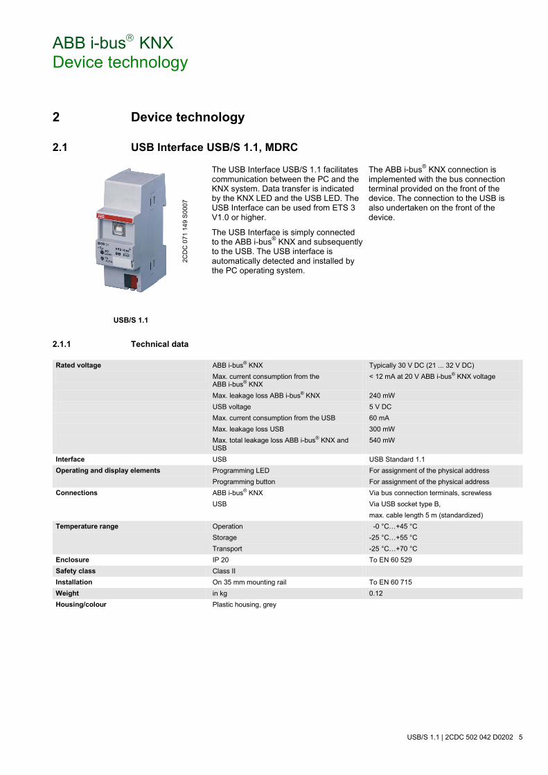
ABB i-bus KNX Device technology
USB/S 1.1 | 2CDC 502 042 D0202 5
2 Device technology
2.1 USB Interface USB/S 1.1, MDRC
USB/S 1.1
The USB Interface USB/S 1.1 facilitates communication between the PC and the KNX system. Data transfer is indicated by the KNX LED and the USB LED. The USB Interface can be used from ETS 3 V1.0 or higher.
The USB Interface is simply connected to the ABB i-bus® KNX and subsequently to the USB. The USB interface is automatically detected and installed by the PC operating system.
The ABB i-bus® KNX connection is implemented with the bus connection terminal provided on the front of the device. The connection to the USB is also undertaken on the front of the device.
2.1.1 Technical data
Rated voltage ABB i-bus® KNX Typically 30 V DC (21 ... 32 V DC) Max. current consumption from the
ABB i-bus® KNX < 12 mA at 20 V ABB i-bus® KNX voltage
Max. leakage loss ABB i-bus® KNX 240 mW USB voltage 5 V DC Max. current consumption from the USB 60 mA Max. leakage loss USB 300 mW Max. total leakage loss ABB i-bus® KNX and
USB 540 mW
Interface USB USB Standard 1.1 Operating and display elements Programming LED For assignment of the physical address Programming button For assignment of the physical address Connections ABB i-bus® KNX Via bus connection terminals, screwless USB Via USB socket type B,
max. cable length 5 m (standardized) Temperature range Operation
Storage Transport
-0 °C…+45 °C -25 °C…+55 °C -25 °C…+70 °C
Enclosure IP 20 To EN 60 529 Safety class Class II Installation On 35 mm mounting rail To EN 60 715 Weight in kg 0.12 Housing/colour Plastic housing, grey
2CD
C 0
71 1
49 S
0007
ABB i-bus KNX Device technology
6 2CDC 502 042 D0202 | USB/S 1.1
Design Modular installation device (MDRC) Modular installation device, Pro M Dimensions 90 x 36 x 64.5 (H x W x D) Mounting width in space units
(modules at 18 mm) 2
Mounting depth in mm 64.5 Installation On 35 mm mounting rail To EN 60 715 Mounting position As required Approvals KNX Certification CE mark In accordance with the EMC guideline and low
voltage guideline
Device type Application program Maximum number of
communication objects Maximum number of group addresses
Maximum number of associations
USB Interface /1 0 0 0
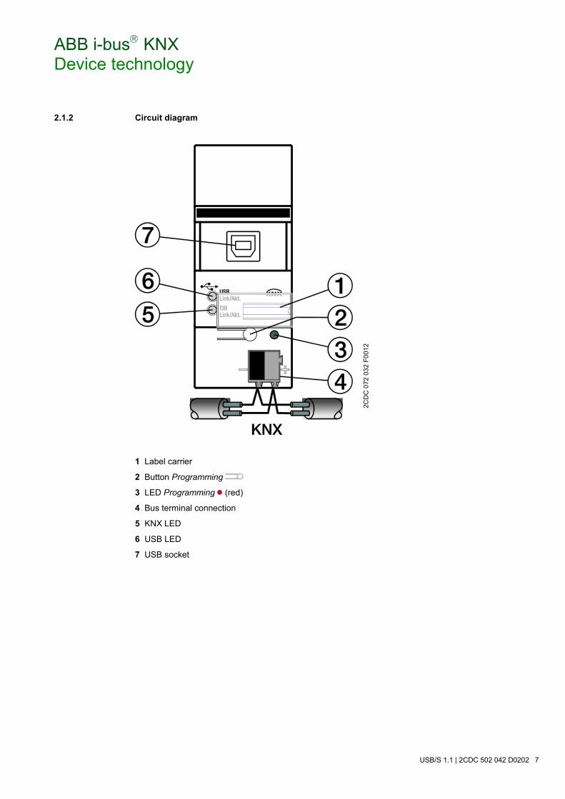
ABB i-bus KNX Device technology
USB/S 1.1 | 2CDC 502 042 D0202 7
2.1.2 Circuit diagram
1 Label carrier
2 Button Programming
3 LED Programming (red)
4 Bus terminal connection
5 KNX LED
6 USB LED
7 USB socket
2CD
C 0
72 0
32 F
0012
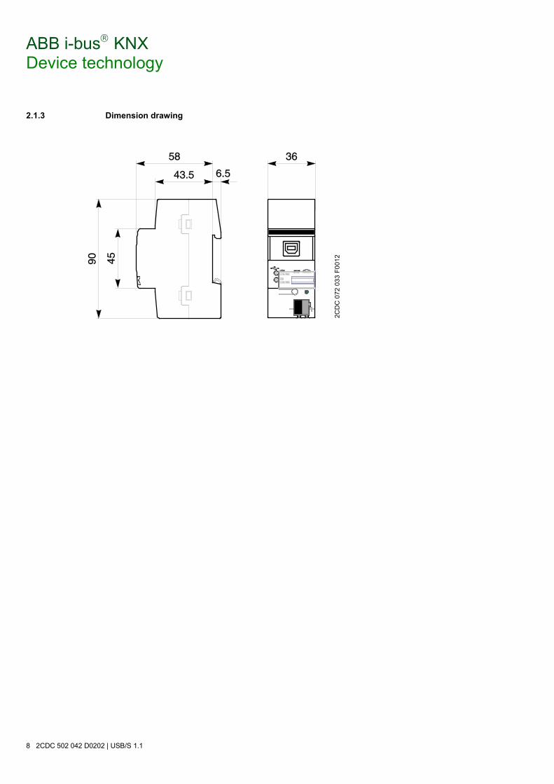
ABB i-bus KNX Device technology
8 2CDC 502 042 D0202 | USB/S 1.1
2.1.3 Dimension drawing
2C
DC
072
033
F00
12
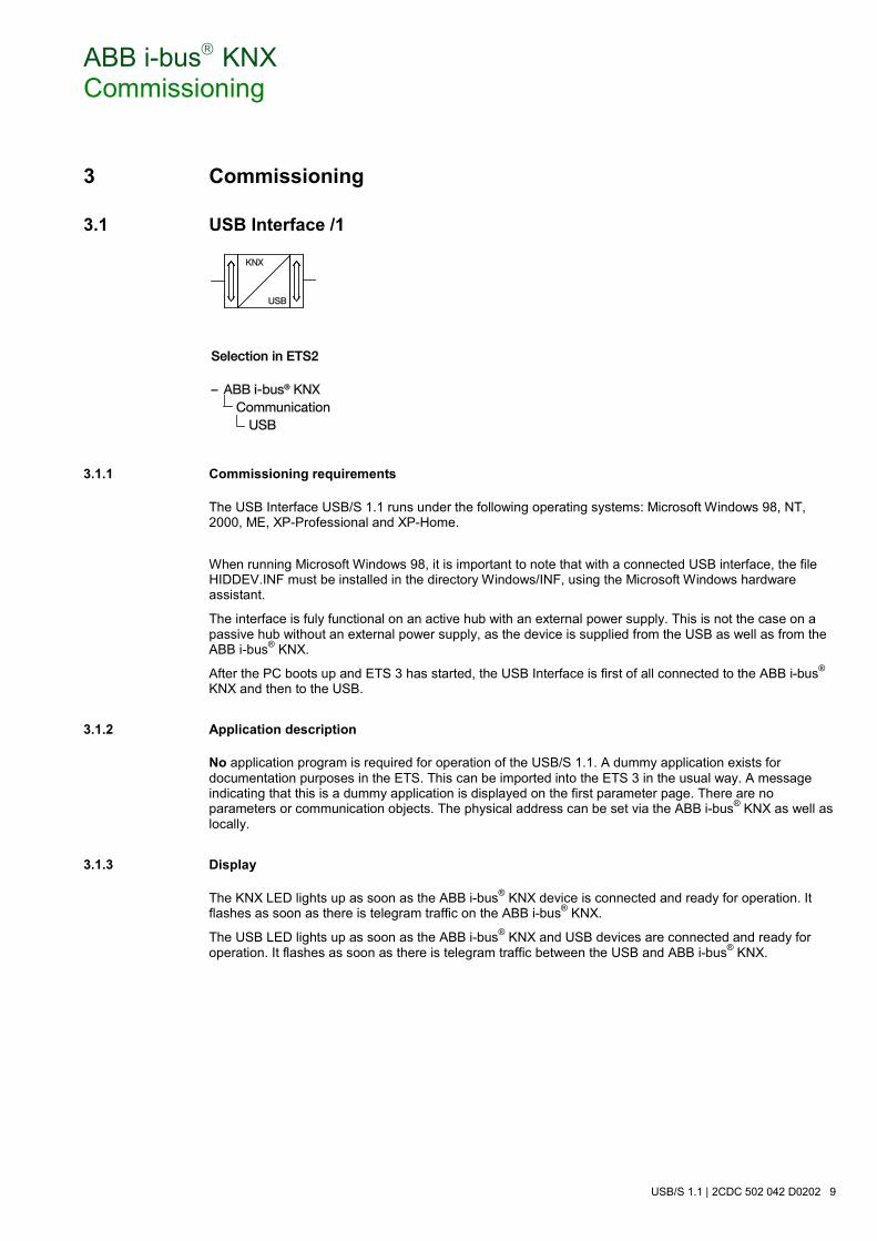
ABB i-bus KNX Commissioning
USB/S 1.1 | 2CDC 502 042 D0202 9
3 Commissioning
3.1 USB Interface /1
3.1.1 Commissioning requirements
The USB Interface USB/S 1.1 runs under the following operating systems: Microsoft Windows 98, NT, 2000, ME, XP-Professional and XP-Home.
When running Microsoft Windows 98, it is important to note that with a connected USB interface, the file HIDDEV.INF must be installed in the directory Windows/INF, using the Microsoft Windows hardware assistant.
The interface is fuly functional on an active hub with an external power supply. This is not the case on a passive hub without an external power supply, as the device is supplied from the USB as well as from the ABB i-bus® KNX.
After the PC boots up and ETS 3 has started, the USB Interface is first of all connected to the ABB i-bus® KNX and then to the USB.
3.1.2 Application description
No application program is required for operation of the USB/S 1.1. A dummy application exists for documentation purposes in the ETS. This can be imported into the ETS 3 in the usual way. A message indicating that this is a dummy application is displayed on the first parameter page. There are no parameters or communication objects. The physical address can be set via the ABB i-bus® KNX as well as locally.
3.1.3 Display
The KNX LED lights up as soon as the ABB i-bus® KNX device is connected and ready for operation. It flashes as soon as there is telegram traffic on the ABB i-bus® KNX.
The USB LED lights up as soon as the ABB i-bus® KNX and USB devices are connected and ready for operation. It flashes as soon as there is telegram traffic between the USB and ABB i-bus® KNX.

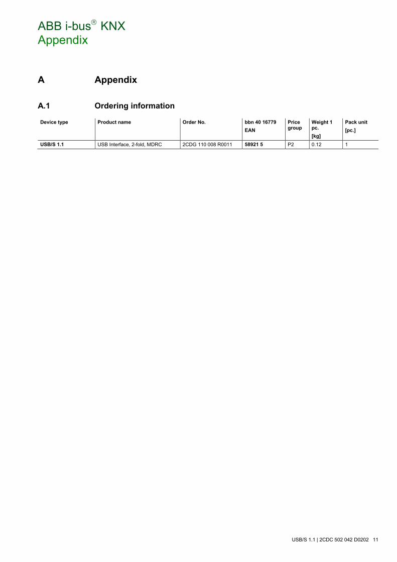
ABB i-bus KNX Appendix
USB/S 1.1 | 2CDC 502 042 D0202 11
A Appendix
A.1 Ordering information
Device type Product name Order No. bbn 40 16779 EAN
Price group
Weight 1 pc. [kg]
Pack unit [pc.]
USB/S 1.1 USB Interface, 2-fold, MDRC 2CDG 110 008 R0011 58921 5 P2 0.12 1

ABB i-bus KNX Appendix
12 2CDC 502 042 D0202 | USB/S 1.1
Notes

ABB STOTZ-KONTAKT GmbH Eppelheimer Straße 82 69123 Heidelberg, Germany Phone: +49 (0)6221 701 607 (Marketing) Fax: +49 (0)6221 701 724 E-mail: [email protected] Further information and local contacts: www.abb.com/knx
Note: We reserve the right to make technical changes to the products as well as amendments to the content of this document at any time without advance notice. The agreed properties are definitive for any orders placed. ABB AG shall not be liable for any consequences arising from errors or incomplete information in this document. We reserve the rights to this document and all the items and illustrations contained therein. Reproduction, transfer to third parties or processing of the content – including sections thereof – is not permitted without prior expressed written permission from ABB AG. Copyright© 2012 ABB All rights reserved
P
ublic
atio
n N
umbe
r 2C
DC
502
042
D02
02 (1
0.12
)
Contact