Product line up for electrochemical research...Motor 12 V, ironless core, low inertial DC servo...
32
Product line up for electrochemical research Electrochemistry General Catalog Counter Electrodes Working Electrodes Reference Electrodes Voltammetry Cells Flow Cells Others Spectroelectrochemistry Instrumentation C3 PROZESS- und ANALYSENTECHNIK GmbH
Transcript of Product line up for electrochemical research...Motor 12 V, ironless core, low inertial DC servo...

Product line up for electrochemical research
Electrochemistry General Catalog
Co
unter Ele
ctro
de
sW
orking
Elec
trod
es
Refe
renc
e Ele
ctro
de
sVo
ltam
me
try Ce
llsFlo
w C
ells
Othe
rsSp
ec
troe
lec
troc
hem
istryInstrum
enta
tion
C3 PROZESS- undANALYSENTECHNIK GmbH

Information
Please confirm the newest information at ALS website www.als-japan.com
ALS website has a "Technical note" and a "Movie library" section, where you can find useful information and introduction movies of our products.The instrument, set-up and application movies will help you choosing the accessories.We are c on t i nuos l y producing and releasing new movies, approaching the demands of the users.
frontpage --> Support --> Electrode data
Instrumentation
Electrodes
Technical notes and Movie library
Inspection data sheet download service
Product manual download service
ALS working and reference electrodes are tested and inspected before shipment, and the data can be reviewed on our web website.In the instruction manual of products where the check data is available, you will find the website direction.
ALS product manuals are available for download on the web.
frontpage --> Technical note
frontpage --> Support --> Instrument Manual
frontpage --> Support --> Products Manual
ALS support product manual
Manual download linkhttps://www.als-japan.com/support-product-manual.html
Manual download link
ALS Instruments instruction manualhttps://www.als-japan.com/support-instrument-manual.html
https://www.als-japan.com/dl/Inspection data sheet link
ALS technical notes and moviehttps://www.als-japan.com/technical-note.html

2
6
11
12
17
20
23
Others 28
● Product appearance and specifications may change without notice. ● The product color could be different from the printed photos. ● The dimensions mentioned in the catalog are not guaranteed to match the dimensions of the actual products.
Instrumentation
Working Electrodes
Counter Electrodes
Reference Electrodes
Voltammetry Cells
••••••••••••••••••••••••
•••••••••••••••••••
••••••••••••••••••••
•••••••••••••••••
•••••••••••••••••••••
••••••••••••••••••••••••••••••••••
••••••••••••••••••••••••••••••••••••••••
12345678
Index
1Please confirm the newest information at ALS website www.als-japan.com
Counter Electrodes
Working Electrodes
Reference Electrodes
Voltamm
etry Cells
Flow C
ellsO
thersSpectroelectrochem
istryInstrum
entation
Spectroelectrochemistry •••••••••••
Flow Cells

RRDE-3A Rotating Ring Disk Electrode Apparatus
Instrumentation
2Please confirm the newest information at ALS website www.als-japan.com
Co
unte
r Ele
ctr
od
es
Wo
rkin
g E
lec
tro
de
sRe
fere
nce
Ele
ctr
od
es
Volta
mm
etr
y C
ells
Flo
w C
ells
Oth
ers
Spe
ctr
oe
lec
tro
che
mis
try
Inst
rum
ent
atio
n 1 InstrumentationRRDE-3A Rotating Ring Disk Electrode Apparatus
Catalog No. Description012623 RRDE-3A Rotating Ring Disk Electrode Apparatus Ver.1.2
SpecificationRotational range 100 to 8,000 rpm
Rotation stability Error: < 2% at < 2,000 rpm < 1% at > 2,000 rpm
Ring/Disk insulation resistance > 10 M ohm
Electrode to lead pin contact resistance 5 ohm
Rotator shaft Stainless steel
Motor 12 V, ironless core, low inertial DC servo
Power 100 - 240 VAC, 50/60 Hz
Remote control1 Volt corresponds to 1,000 rpm Motor ON/OFF TTL or relay input to back panel
Connection Purge TTL or relay input to back panel connection
Operating temperature 10 to 50 deg C
Relative humidity ≤ 80%
Size 190 x (Base: 230, Body: 120) x 400 mm
Weight 6 kg
Accessories Qty(013580) Sample vial for alkaline solution (100mL) 1
013271 RRDE-3A Teflon cap V.2 1
012064 Spin coating adapter 1
012065 Male connector for gas purge (PP) 1
013392 TYGON tubing, OD1/4" x ID1/8" 1
012642 RRDE-3A Sillicon sheet 100 x 180 mm 1
012976 O-ring for RRDE-3A shaft assembly 3
012975 O-ring for RRDE-3A Bearing assembly 3
Power supply cable 1
Instruction manual 1
Catalog No. Description013580 Sample vial for alkaline solution (100mL) (10 pcs)
013581 Sample vial for alkaline solution (200mL) (8 pcs)
012632 Sample vial (100mL)
012177 Sample holder dia 9 mm (2 pcs)
012167 RE-1B Reference electrode (Ag/AgCl)
012171 RE-7 Non Aqueous reference electrode (Ag/Ag+)
012961 Platinum counter electrode 23 cm
012962 Gold counter electrode 23 cm
012963 Nickel counter electrode 23 cm
013343 O-ring for RRDE-3A Teflon cap V.2
012829 O-ring for RRDE-3A shaft assembly (10 pcs)
012641 O-ring for RRDE-3A Bearing assembly (10 pcs)
Detection of intermediate products by hydrodynamic voltammetry
Feature
�������������� ������� ����������� ���te and ������ controlled rotation speed and gas purge�������������������������������������������������������������������������������
ALS support RRDE
Support Movie linkhttps://www.als-japan.com/support-rrde.html
Manual download link
ALS Instruments instruction manualhttps://www.als-japan.com/support-instrument-manual.html
NEW
NEW
RRDA-3A is an accurate rotator system for hydrodynamic modulation rotating ring disk voltammmetry. The rotation speed is precisely controlled by PLL(phase-locked loop). Electrodes are small and rapidly interchangeable. The unit also provides an adjustable valve system for inert gas purging inside the cell vial.
Co
unter Ele
ctro
de
sW
orking
Elec
trod
es
Refe
renc
e Ele
ctro
de
sVo
ltam
me
try Ce
llsFlo
w C
ells
Othe
rsSp
ec
troe
lec
troc
hem
istry
Electrodes and accessories
Instrumentation
3Please confirm the newest information at ALS website www.als-japan.com
Instrume
ntatio
n
012613 012616 012615
012614011169
011170011171
Electrodes and accessories
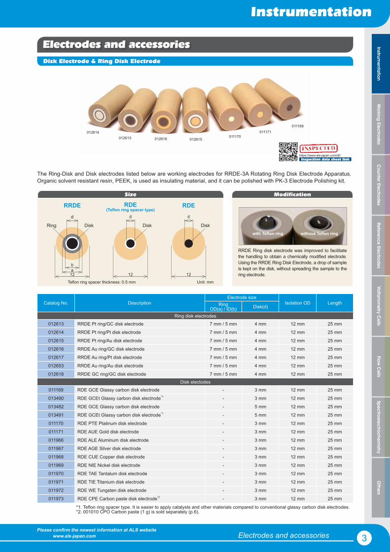
The Ring-Disk and Disk electrodes listed below are working electrodes for RRDE-3A Rotating Ring Disk Electrode Apparatus. Organic solvent resistant resin, PEEK, is used as insulating material, and it can be polished with PK-3 Electrode Polishing kit.
Catalog No. DescriptionElectrode size
Isolation OD LengthRingOD(a) / ID(b) Disk(d)
Ring disk electrodes012613 RRDE Pt ring/GC disk electrode 7 mm / 5 mm 4 mm 12 mm 25 mm
012614 RRDE Pt ring/Pt disk electrode 7 mm / 5 mm 4 mm 12 mm 25 mm
012615 RRDE Pt ring/Au disk electrode 7 mm / 5 mm 4 mm 12 mm 25 mm
012616 RRDE Au ring/GC disk electrode 7 mm / 5 mm 4 mm 12 mm 25 mm
012617 RRDE Au ring/Pt disk electrode 7 mm / 5 mm 4 mm 12 mm 25 mm
012653 RRDE Au ring/Au disk electrode 7 mm / 5 mm 4 mm 12 mm 25 mm
012618 RRDE GC ring/GC disk electrode 7 mm / 5 mm 4 mm 12 mm 25 mmDisk electodes
011169 RDE GCE Glassy carbon disk electrode - 3 mm 12 mm 25 mm
013490 RDE GCEt Glassy carbon disk electrode*1 - 3 mm 12 mm 25 mm
013482 RDE GCE Glassy carbon disk electrode - 5 mm 12 mm 25 mm
013491 RDE GCEt Glassy carbon disk electrode*1 - 5 mm 12 mm 25 mm
011170 RDE PTE Platinum disk electrode - 3 mm 12 mm 25 mm
011171 RDE AUE Gold disk electrode - 3 mm 12 mm 25 mm
011966 RDE ALE Aluminum disk electrode - 3 mm 12 mm 25 mm
011967 RDE AGE Silver disk electrode - 3 mm 12 mm 25 mm
011968 RDE CUE Copper disk electrode - 3 mm 12 mm 25 mm
011969 RDE NIE Nickel disk electrode - 3 mm 12 mm 25 mm
011970 RDE TAE Tantalum disk electrode - 3 mm 12 mm 25 mm
011971 RDE TIE Titanium disk electrode - 3 mm 12 mm 25 mm
011972 RDE WE Tungsten disk electrode - 3 mm 12 mm 25 mm
011973 RDE CPE Carbon paste disk electrode*2 - 3 mm 12 mm 25 mm
*1. Teflon ring spacer type. It is easier to apply catalysts and other materials compared to conventional glassy carbon disk electrodes.*2. 001010 CPO Carbon paste (1 g) is sold separately (p.6).
Modification
RRDE Ring disk electrode was improved to facilitate the handling to obtain a chemically modified electrode. Using the RRDE Ring Disk Electrode, a drop of sample is kept on the disk, without spreading the sample to the ring electrode.
without Teflon ringwith Teflon ring
Disk Electrode & Ring Disk Electrode
https://www.als-japan.com/dl/Inspection data sheet link
Size
ba
12
d
Ring Disk
RRDE
Unit: mm
d
12
Disk
RDE(Teflon ring spacer type)
d
12
Disk
RDE
Teflon ring spacer thickness: 0.5 mm

Electrodes and accessories
Instrumentation
4Please confirm the newest information at ALS website www.als-japan.com
Cou
nter
Ele
ctro
des
Wor
king
Ele
ctro
des
Ref
eren
ce E
lect
rode
sVo
ltam
met
ry C
ells
Flow
Cel
lsO
ther
sSp
ectro
elec
troch
emis
tryIn
stru
men
tatio
n
DRE Disk Replaceable Electrode
The Disk Replaceable Electrode (DRE) has a removable disk electrode. The replacement of the disk electrode is possible from both sides, front side and rear side. It enables a selection according to the condition required for your research purpose.In
sert
Catalog No. Description013340 DRE-DCP Disk electrode polishing and exchanging tool kit
Contents Qty
DRE-BLK Base block 1
DRE-STP Stopper 1
DRE-DRS Disk remove tool 1
DRE-SPS Spacer push tool 1
DRE-DPS Disk push tool 1
DRE-EPH Electrode polishing holder 1
DRE-DCP Disk electrode polishing and exchanging tool kit
Catalog No. Description013336 DRE-PGK Pt ring/GC disk replaceable electrode kit
Contents Qty
013337 DRE-PTR Pt ring assembly 1
013339 DRE-SPC Teflon spacer 3
013338 DRE-GCD GC disk 1
Optional items Qty
013366 DRE-AUD Au disk 1
013367 DRE-PTD Pt disk 1
DRE Disk Replaceable Electrode (RRDE)
013337013339
013338
013339
Catalog No. Description013362 DRE-GCK GC disk replaceable electrode kit
013364 DRE-AUK Au disk replaceable electrode kit
013365 DRE-PTK Pt disk replaceable electrode kit
Contents common for the kits Qty
013361 DRE-DAS Disk assembly 1
013339 DRE-SPC Teflon spacer 3
Optional items Qty
013338 DRE-GCD GC disk 1
013366 DRE-AUD Au disk 1
013367 DRE-PTD Pt disk 1
DRE Disk Replaceable Electrode (RDE)
01333
013338
013361
Feature
Assessment of the disk electrode using the same ring electrode, 1. ������������������������������������������������������!Removable disk and ring assembly enables the ����"����� of 2. the electrode surface and the polishing process, separately.Disposable disks can be used.3.
ALS support product manual
Manual download linkhttps://www.als-japan.com/support-product-manual.html https://www.als-japan.com/dl/
Inspection data sheet link
ININNNININININININIININIININIININININSPSPSPSPSPPPSPSPSPSPSPSPSPPPSPSPSPSPSPSPSPSS ECECECECECECECECECECECECEECCECEECECECCE TETETETTETETETETETETETTETTETTETETETTEEET DDDDDDDDDDDDDDDDDDDDDDD

Counter Electrodes
Working Electrodes
Reference Electrodes
Voltamm
etry Cells
Flow C
ellsO
thersSpectroelectrochem
istry
Electrodes and accessories
Instrumentation
5Please confirm the newest information at ALS website www.als-japan.com
Instrumentation
Handling procedure for the DRE
The DRE-STP Stopper is screwed into the DRE-PTR Pt ring assembly. It is used for the adjustment of the height, after the DRE-SPC Teflon spacer and DRE-GCD GC disk are attached. The “A” side of the DRE-BLK Base block is used for the DRE-SPC Teflon spacer attachment, and “B” side is for the DRE-GCD GC disk attachment.
After attaching the DRE-SPC Teflon spacer into the DRE-PTR Pt ring assembly on the "A" side and adjusting the height, move theDRE-PTR Pt ring assembly to the "B" side, to fit the DRE-GCD GC disk from the front side, as shown above.Put the DRE-GCD GC disk from the front side (Fig. 1) and adjust it with DRE-DPS Disk push tool (Fig. 2).Take out from the DRE-BLK Base block and adjust the height with DRE-STP Stopper and DRE-DRS Disk remove tool, until it is flush with the surrounding surface (Fig. 3).
RRDE Disk replaceable electrode assessment test
The illustration in the section above shows the fitting of the DRE-GCD Glassy carbon disk from the front side, however for the performance test of the electrode, both ways, front side and rear side were done.
Typical test parameters are:
Working electrode : DRE-RRDE Pt ring GC disk electrodeReference electrode: Ag/AgClCounter electrode : Platinum wireTest solution : 2 mM potassium ferricyanide/1 M KNO3
Initial voltage : + 600 mVFinal voltage : - 200 mVScan Rate (Volt) : 10 mV/SRotation Rate : 100 to 3,000 rpmSensitivity : 10-5 A/V2nd potential : + 600 mV
Fitting from the front side: Fitting from the rear side:
3.00E-04
2.50E-04
2.00E-04
1.50E-04
1.00E-04
5.00E-05
0.00E+00
-5.00E-05
-1.00E-04
-1.50E-04
Cur
rent
(A)
0.6 0.5 0.4 0.3 0.2 0.1 0 -0.1 -0.2Potential (V)
Front_Side_Assembling_Method
Disk Potential Rang : From 0.6V to -0.2VScan Speed : 0.01V/sRing Potential : 0.6V
100 rpm200 rpm400 rpm700 rpm1000 rpm1500 rpm2000 rpm2500 rpm3000 rpm
2.00E-04
1.50E-04
1.00E-04
5.00E-05
0.00E+00
-5.00E-05
-1.00E-04
Cur
rent
(A)
0.6 0.5 0.4 0.3 0.2 0.1 0 -0.1 -0.2Potential (V)
Rear_Side_Assembling_Method
Disk Potential Rang : From 0.6V to -0.2VScan Speed : 0.01V/sRing Potential : 0.6V
100 rpm200 rpm400 rpm700 rpm1000 rpm1500 rpm
Fig.1 Fig.2 Fig.3
GC Disk Disk push tool
Stopper
GC Disk
Base Block
Pt ring assembly+
Teflon spacer
ALS support RRDE
Support Movie linkhttp://www.als-japan.com/support-rrde.html

General Working Electrodes for Voltammetry
Working Electrodes
6Please confirm the newest information at ALS website www.als-japan.com
Cou
nter
Ele
ctro
des
Wor
king
Ele
ctro
des
Ref
eren
ce E
lect
rode
sVo
ltam
met
ry C
ells
Flow
Cel
lsO
ther
sSp
ectro
elec
troch
emis
tryIn
stru
men
tatio
n
Standardtype
Small type Gauze type
6 315
55
15 55
Micro type
4
70
35
2325
10
6
Brass roddia. 1.6
*1. O-ring, one is attached to the electrode.
*2. For OD: 10 mm working electrode, the SVC-2 is recommended.
15110
6
Long type
Units: mm
General Working Electrodes for Voltammetry
2 Working Electrodes
CPO Carbon Paste Oil
Carbon Paste Oil (CPO) is prepared by mixing uniform-sized graphite powder and paraffin oil. This product is applied to Carbon Paste Electrodes to have:
1) simple enzyme electrodes2) chemically modified electrodes
Catalog No. Description001010 CPO Carbon paste oil base (1 g)
1) Mix and homogenize the compound to be analyzed in the CPO 2) Fill tightly into the electrode hole with a small spatula 3) Remove the excess CPO and polish the surface of the electrode with circular movement on a clean paper
001010
O-ring*1
It can not be used in organic solvents. Keep the container closed to avoid contamination.
Purpose
Standard type:
Long type:Small type:Micro type:Gauze type:
The most common electrode. It could be used in SVC-2, SVC-3 and VC-4 voltammetry cells*2
PEEK body of 110 mmOD: 3 mm, for measurement of the small sample volumes #����������������������������������������$���������%�����Used for bulk electrolysis and as a counter electrode
How to prepare carbon paste electrode:
Spare O-rings are available separately, 002247 O-ring for CV electrode (10 pcs), 011054 O-ring for Micro electrode(10pcs).
General Working Electrodes for Voltammetry
Working Electrodes
7Please confirm the newest information at ALS website www.als-japan.com
Counter Electrodes
Working Electrodes
Reference Electrodes
Voltamm
etry Cells
Flow C
ellsO
thersSpectroelectrochem
istryInstrum
entation
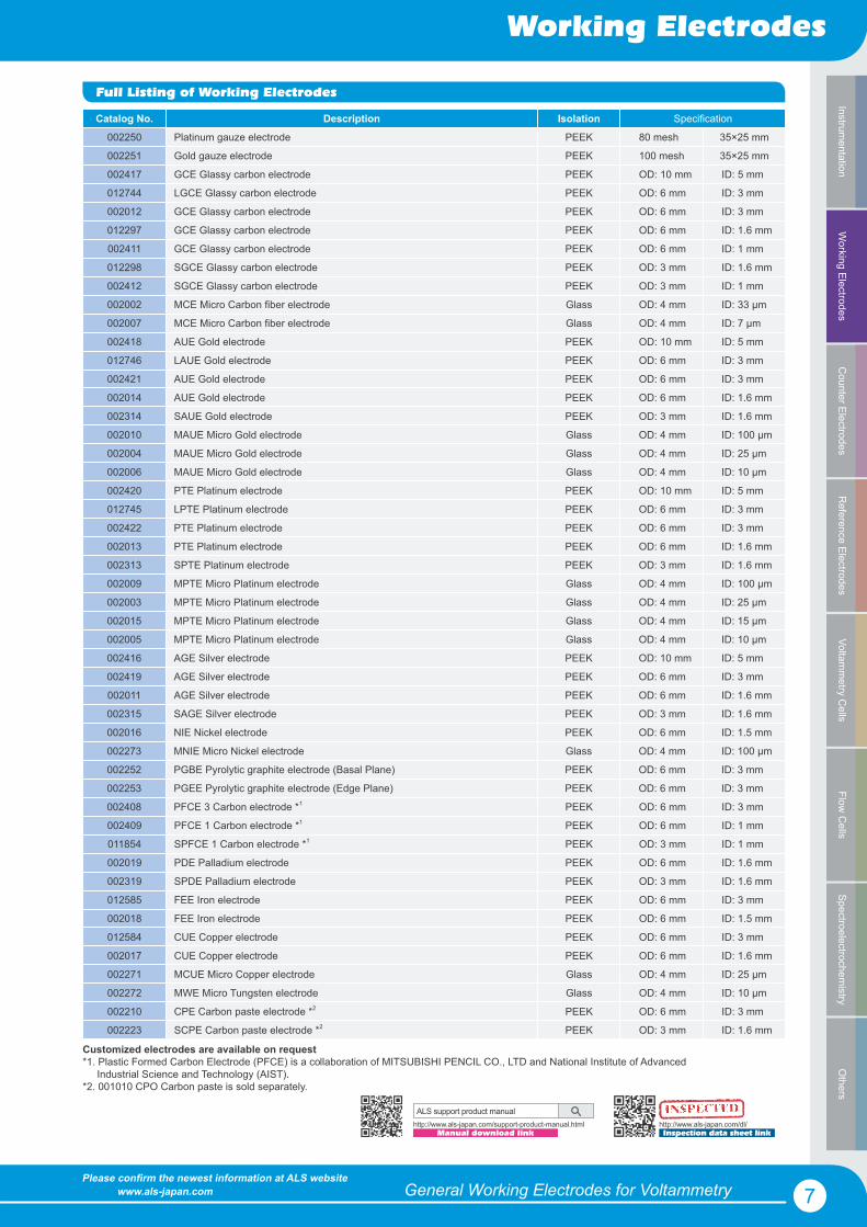
Full Listing of Working Electrodes
Customized electrodes are available on request *1. Plastic Formed Carbon Electrode (PFCE) is a collaboration of MITSUBISHI PENCIL CO., LTD and National Institute of Advanced Industrial Science and Technology (AIST).*2. 001010 CPO Carbon paste is sold separately.
Catalog No. Description Isolation Specification
002250 Platinum gauze electrode PEEK 80 mesh 35×25 mm
002251 Gold gauze electrode PEEK 100 mesh 35×25 mm
002417 GCE Glassy carbon electrode PEEK OD: 10 mm ID: 5 mm
012744 LGCE Glassy carbon electrode PEEK OD: 6 mm ID: 3 mm
002012 GCE Glassy carbon electrode PEEK OD: 6 mm ID: 3 mm
012297 GCE Glassy carbon electrode PEEK OD: 6 mm ID: 1.6 mm
002411 GCE Glassy carbon electrode PEEK OD: 6 mm ID: 1 mm
012298 SGCE Glassy carbon electrode PEEK OD: 3 mm ID: 1.6 mm
002412 SGCE Glassy carbon electrode PEEK OD: 3 mm ID: 1 mm
002002 MCE Micro Carbon fiber electrode Glass OD: 4 mm ID: 33 μm
002007 MCE Micro Carbon fiber electrode Glass OD: 4 mm ID: 7 μm
002418 AUE Gold electrode PEEK OD: 10 mm ID: 5 mm
012746 LAUE Gold electrode PEEK OD: 6 mm ID: 3 mm
002421 AUE Gold electrode PEEK OD: 6 mm ID: 3 mm
002014 AUE Gold electrode PEEK OD: 6 mm ID: 1.6 mm
002314 SAUE Gold electrode PEEK OD: 3 mm ID: 1.6 mm
002010 MAUE Micro Gold electrode Glass OD: 4 mm ID: 100 μm
002004 MAUE Micro Gold electrode Glass OD: 4 mm ID: 25 μm
002006 MAUE Micro Gold electrode Glass OD: 4 mm ID: 10 μm
002420 PTE Platinum electrode PEEK OD: 10 mm ID: 5 mm
012745 LPTE Platinum electrode PEEK OD: 6 mm ID: 3 mm
002422 PTE Platinum electrode PEEK OD: 6 mm ID: 3 mm
002013 PTE Platinum electrode PEEK OD: 6 mm ID: 1.6 mm
002313 SPTE Platinum electrode PEEK OD: 3 mm ID: 1.6 mm
002009 MPTE Micro Platinum electrode Glass OD: 4 mm ID: 100 μm
002003 MPTE Micro Platinum electrode Glass OD: 4 mm ID: 25 μm
002015 MPTE Micro Platinum electrode Glass OD: 4 mm ID: 15 μm
002005 MPTE Micro Platinum electrode Glass OD: 4 mm ID: 10 μm
002416 AGE Silver electrode PEEK OD: 10 mm ID: 5 mm
002419 AGE Silver electrode PEEK OD: 6 mm ID: 3 mm
002011 AGE Silver electrode PEEK OD: 6 mm ID: 1.6 mm
002315 SAGE Silver electrode PEEK OD: 3 mm ID: 1.6 mm
002016 NIE Nickel electrode PEEK OD: 6 mm ID: 1.5 mm
002273 MNIE Micro Nickel electrode Glass OD: 4 mm ID: 100 μm
002252 PGBE Pyrolytic graphite electrode (Basal Plane) PEEK OD: 6 mm ID: 3 mm
002253 PGEE Pyrolytic graphite electrode (Edge Plane) PEEK OD: 6 mm ID: 3 mm
002408 PFCE 3 Carbon electrode *1 PEEK OD: 6 mm ID: 3 mm
002409 PFCE 1 Carbon electrode *1 PEEK OD: 6 mm ID: 1 mm
011854 SPFCE 1 Carbon electrode *1 PEEK OD: 3 mm ID: 1 mm
002019 PDE Palladium electrode PEEK OD: 6 mm ID: 1.6 mm
002319 SPDE Palladium electrode PEEK OD: 3 mm ID: 1.6 mm
012585 FEE Iron electrode PEEK OD: 6 mm ID: 3 mm
002018 FEE Iron electrode PEEK OD: 6 mm ID: 1.5 mm
012584 CUE Copper electrode PEEK OD: 6 mm ID: 3 mm
002017 CUE Copper electrode PEEK OD: 6 mm ID: 1.6 mm
002271 MCUE Micro Copper electrode Glass OD: 4 mm ID: 25 μm
002272 MWE Micro Tungsten electrode Glass OD: 4 mm ID: 10 μm
002210 CPE Carbon paste electrode *2 PEEK OD: 6 mm ID: 3 mm
002223 SCPE Carbon paste electrode *2 PEEK OD: 3 mm ID: 1.6 mm
ALS support product manual
Manual download linkhttp://www.als-japan.com/support-product-manual.html http://www.als-japan.com/dl/
Inspection data sheet link
ININNNINININNININIINININIININININNININSPSPSPSPSPSPSPSPSPSPSPSPSPSPSSPSSPSPPPSSS ECECECECCECECECECEECECECECECECECCECECECECECEECECCTETETETETETETTTETETETEETETETETETETTETTET DDDDDDDDDDDDDDDDDDDD
Working Electrodes
8Please confirm the newest information at ALS website www.als-japan.com
Cou
nter
Ele
ctro
des
Wor
king
Ele
ctro
des
Ref
eren
ce E
lect
rode
sVo
ltam
met
ry C
ells
Flow
Cel
lsO
ther
sSp
ectro
elec
troch
emis
tryIn
stru
men
tatio
n Lithography / Glass substrate ElectrodesRing-Disk electrode
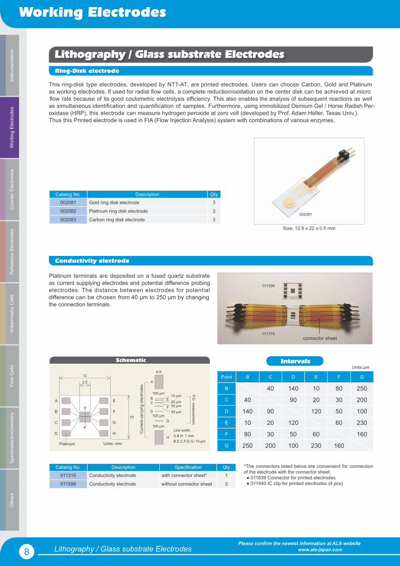
This ring-disk type electrodes, developed by NTT-AT, are printed electrodes. Users can choose Carbon, Gold and Platinum as working electrodes. If used for radial flow cells, a complete reduction/oxidation on the center disk can be achieved at micro flow rate because of its good coulometric electrolysis efficiency. This also enables the analysis of subsequent reactions as well as simultaneous identification and quantification of samples. Furthermore, using immobilized Osmium Gel / Horse Radish Per- oxidase (HRP), this electrode can measure hydrogen peroxide at zero volt (developed by Prof. Adam Heller, Texas Univ.). Thus this Printed electrode is used in FIA (Flow Injection Analysis) system with combinations of various enzymes.
Catalog No. Description Qty002081 Gold ring disk electrode 3
002082 Platinum ring disk electrode 3
002083 Carbon ring disk electrode 3
Conductivity electrode
Platinum terminals are deposited on a fused quartz substrate as current supplying electrodes and potential difference probing electrodes. The distance between electrodes for potential difference can be chosen from 40 μm to 250 μm by changing the connection terminals.
connector sheet011316
011598
Point B C D E F G
B 40 140 10 80 250
C 40 90 20 30 200
D 140 90 120 50 100
E 10 20 120 60 230
F 80 30 50 60 160
G 250 200 100 230 160
Catalog No. Description Specification Qty011316 Conductivity electrode with connector sheet* 1
011598 Conductivity electrode without connector sheet 3
Units:: μm
*The connectors listed below are convenient for connection of the electrode with the connector sheet. ● 011839 Connector for printed electrodes ● 011840 IC clip for printed electrodes (4 pcs)
Size: 12.5 x 22 x 0.5 mm
002081
IntervalsSchematic
12
2.5
A
G
F
E
D
C
B
H
a
a'
Platinum
10
a-a'
A
D
CB
G
F
E
H
100 μm
100 μm
10 μm20 μm 30 μm
100 μm50 μm
Units: mm
Line width: A & H: 1 mmB,E,C,F,D,G: 10 μm
Cur
rent
-car
ryin
g el
ectro
des
P.D. m
easurement
Lithography / Glass substrate Electrodes

Working Electrodes
9Please confirm the newest information at ALS website www.als-japan.com
Counter Electrodes
Working Electrodes
Reference Electrodes
Voltamm
etry Cells
Flow C
ellsO
thersSpectroelectrochem
istryInstrum
entation
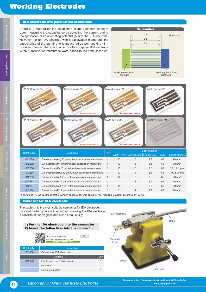
IDA electrodes
Interdigitated Array electrodes (IDA) are electrodes developed for electrochemical measurements to be performed with avery small quantity of the sample. IDA electrodes can be used for the detection and reaction analysis of compounds. The IDAelectrode itself is a microelectrode pattern fabricated by using lithography technology. The electrode array consists of 65 pairs,each one of the pairs works as an oxidation and a reduction electrode. .
IDA-Au 10 μm
IDA-Pt 10 μm
IDA-C 10 μm
IDA-ITO 10 μm
IDA-Au 3 μm
IDA-Pt 3 μm
IDA-Au 2 μm
IDA-Pt 2 μm
Working electrode #1
Reference electrode
Counter electrode
Passivation membrane
Working electrode #2
12
20
2
Quartz plate, t = 0.5 mm
Unit: mm
Catalog No. Description QtySpecification
Width (μm) Interval (μm) Length (mm) pairs Film thickness
012125 IDA electrode (Au) 10 μm 1 10 5 2 65 90 nm*
012126 IDA electrode (Pt) 10 μm 1 10 5 2 65 90 nm*
012127 IDA electrode (C) 10 μm 1 10 5 2 65 1.2 ± 0.1 μm
012128 IDA electrode (ITO) 10 μm 1 10 5 2 65 100 ± 20 nm
012129 IDA electrode (Au) 3 μm 1 3 3 2 65 90 nm*
012130 IDA electrode (Pt) 3 μm 1 3 3 2 65 90 nm*
012257 IDA electrode (Au) 2 μm 1 2 2 2 65 90 nm*
012258 IDA electrode (Pt) 2 μm 1 2 2 2 65 90 nm*
011066 Cable kit for IDA electrode 1
011464 Ag/AgCl Ink for reference electrode (2.0 mL) 1
HIGH SENSITIVITY
HIGH SENSITIVITY
EXTRA SENSITIVITY
EXTRA SENSITIVITY
Features
��#��������������&����������������������������������������������������'�����������������������������������������(���#���)��������������
Applications
������������������������������������������������������+���������5���������������������������������"���������������������������������������������
* For Au and Pt, the thickness of the titanium adhesive layer is about 10 nm, resulting in a total thickness of 100 nm.
6����������5�7���������������������
ALS support product manual
Manual download linkhttps://www.als-japan.com/support-product-manual.html
Working Electrodes
10Please confirm the newest information at ALS website www.als-japan.com
Cou
nter
Ele
ctro
des
Wor
king
Ele
ctro
des
Ref
eren
ce E
lect
rode
sVo
ltam
met
ry C
ells
Flow
Cel
lsO
ther
sSp
ectro
elec
troch
emis
tryIn
stru
men
tatio
n
Lithography / Glass substrate Electrodes
IDA-Au 2 μm w/o PM
IDA-Pt 3 μm w/o PM
IDA-C 10 μm w/o PM
IDA-Pt 2 μm w/o PM
IDA-Au 10 μm w/o PM
IDA-ITO 10 μm w/o PMIDA-Pt 10 μm w/o PM
IDA-Au 3 μm w/o PM
HIGH SENSITIVITY EXTRA SENSITIVITY
IDA electrode w/o passivation membrane
There is a method for the calculation of the dielectric constantupon measuring the capacitance by detecting the current duringthe application of an alternating potential (AC) to the IDA electrode.However, for an IDA electrode with a passivation membrane, thecapacitance of the membrane is measured as well, making it im-possible to obtain the exact value. For this purpose, IDA electrodewithout passivation membrane were added to the product line-up.
Catalog No. Description QtySpecifications
Width (μm) Interval (μm) Length (mm) pairs Film thickness
012259 IDA electrode (Au) 10 μm without passivation membrane 1 10 5 2.5 65 90 nm*
012262 IDA electrode (Pt) 10 μm without passivation membrane 1 10 5 2.5 65 90 nm*
012266 IDA electrode (C) 10 μm without passivation membrane 1 10 5 2.5 65 1.2 ± 0.1 μm
012265 IDA electrode (ITO) 10 μm without passivation membrane 1 10 5 2.5 65 100 ± 20 nm
012260 IDA electrode (Au) 3 μm without passivation membrane 1 3 3 2.5 65 90 nm*
012263 IDA electrode (Pt) 3 μm without passivation membrane 1 3 3 2.5 65 90 nm*
012261 IDA electrode (Au) 2 μm without passivation membrane 1 2 2 2.5 65 90 nm*
012264 IDA electrode (Pt) 2 μm without passivation membrane 1 2 2 2.5 65 90 nm*
Cable kit for IDA electrode
Catalog No. Description011066 Cable kit for IDA electrode
Contents Qty
012970 Electrode Fixer (Teflon plate) 1
Mini vice 1
Connecting cable 1
The cable kit is the most suitable connector for IDA electrode.Be careful when you are inserting or removing the IDA electrode, it consists of quartz glass and it can break easily.
1) Put the IDA electrode into the connector2) Inser������������xer into the connector
IDA electrode
ElectrodeFixer
mini vice
Cable
011066
Schematics
2.6
2.4
2.5
Working electrode 1(Anode)
Working electrode 2(Cathode)
Units: mm
HIGH SENSITIVITY EXTRA SENSITIVITY
* For Au and Pt, the thickness of the titanium adhesive layer is about 10 nm, resulting in a total thickness of 100 nm.
ALS IDA cable kit movie
Support Movie linkhttps://www.als-japan.com/1681.html

11Please confirm the newest information at ALS website www.als-japan.com
Counter Electrodes
Working Electrodes
Reference Electrodes
Voltamm
etry Cells
Flow C
ellsO
thersSpectroelectrochem
istryInstrum
entationCounter Electrodes
Counter Electrodes
Four different shapes of counter electrodes are available. Select the counter electrode suitable for your experimental conditions. Custom-made counter electrodes are available on request.
Catalog No. Description Purpose002222 Platinum counter electrode 5.7 cm SVC-2, VC-4, Plate Material Evaluating cell
002233 Platinum counter electrode 5 cm SVC-3
012961 Platinum counter electrode 23 cm RRDE, Bulk electrolysis, SVC-3
012962 Gold counter electrode 23 cm RRDE, Bulk electrolysis, SVC-3
012963 Nickel counter electrode 23 cm RRDE, Bulk electrolysis, SVC-3
012198 Counter electrode for Flow cell stainless steel pipe, for Flow cell (LC, EQCM, SEC-2F)
3 Counter Electrodes
002222
002233
012961 012962 012963
012198
30 mm
4 mm
15 mm
50 mm
57 mm
For a system using a three-electrode potentiostat, current is measured while a requested potential is adjusted betweenworking electrode and reference electrode. The passage of current through an electrical circuit requires an electron transferprocess between working electrode and counter electrode. The main function of the counter electrode is to provide alocation for the second electron transfer reaction. The surface area is an important parameter of a counter electrode. Itshould be large enough to support the current generated for the working electrode. For example, the surface area of aPlatinum electrode 5 cm in length is sufficient for using it for steady-state cyclic voltammetry experiments. However, forperforming high current measurements such as bulk electrolysis, a counter electrode of a larger area is required, suchas Catalog No.012961 with the length of Platinum of 23 cm. This electrode can also be used for experiments with arotating ring disk setup.
The cell shape is important as well. For electrolysis, the counter electrode is placed in a separate chamber isolated fromthe working electrode to avoid contamination of the product with reaction products generated on the counter electrode. Forelectrochemical measurements like cyclic voltammetry, the effects of contamination can be ignored because of the shortmeasurement time. Therefore, the counter electrode usually is not isolated. In some cases, the separation of the counterelectrode in a chamber increases the resistance between counter electrode and reference electrode, due to the sinteredglass frit. However, in the case of bulk electrolysis, because of long measurement times, the agitation and the separationof the working electrode and counter electrode using a chamber is necessary, to prevent the transfer of substancesbetween two electrodes.
The role of Counter electrodes
Technical note
Working Electrodes
Working Electrodes
Reference Electrodes
Reference Electrodes
12Please confirm the newest information at ALS website www.als-japan.com
Cou
nter
Ele
ctro
des
Wor
king
Ele
ctro
des
Ref
eren
ce E
lect
rode
sVo
ltam
met
ry C
ells
Flow
Cel
lsO
ther
sSp
ectro
elec
troch
emis
tryIn
stru
men
tatio
n
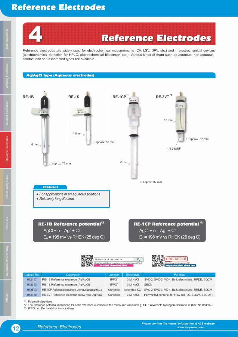
Reference ElectrodesReference electrodes are widely used for electrochemical measurements (CV, LSV, DPV, etc.) and in electrochemical devices (electrochemical detection for HPLC, electrochemical biosensor, etc.). Various kinds of them such as aqueous, non-aqueous, calomel and self-assembled types are available.
Ag/AgCl type (Aqueous electrodes)
Catalog No. Description Junction Electrolyte Purpose012167 RE-1B Reference electrode (Ag/AgCl) IPPG 3 M NaCl SVC-2, SVC-3, VC-4, Bulk electrolysis, RRDE, EQCM
013393 RE-1S Reference electrode (Ag/AgCl) IPPG 3 M NaCl SECM
013503 RE-1CP Reference electrode (Ag/AgCl/Saturated KCl) Ceramics saturated KCl SVC-2, SVC-3, VC-4, Bulk electrolysis, RRDE, EQCM
013488 RE-3VT Reference electrode screw type (Ag/AgCl) Ceramics 3 M NaCl Polymethyl pentene, for Flow cell (LC, EQCM, SEC-2F)
RE-1B RE-1S RE-1CP RE-3VT
6 mm
4.5 mm
6 mm
10 mm
1/4 28UNF
4 Reference Electrodes
L: approx. 78 mm
L: approx. 52 mm
L: approx. 92 mm
L: approx. 52 mm
RE-1CP Reference potential AgCl + e = Ag+ + Cl-
E0 = 198 mV vs RHEK (25 deg C)
RE-1B Reference potential AgCl + e = Ag+ + Cl-
E0 = 195 mV vs RHEK (25 deg C)
Features
� For applications in an aqueous solutions� Relatively long life time
*1*1
*1. Polymethyl pentene*2. The reference potential mentioned for each reference electrode is the measured value using RHEK reversible hydrogen electrode kit (Cat. No.013597).*3. IPPG: Ion Permeability Porous Glass
*3
*3
*2*2
*3
*3
*2*2
*3
*3
*2*2
*3
*3
*2*2
ALS support product manual
Manual download linkhttps://www.als-japan.com/support-product-manual.html https://www.als-japan.com/dl/
Inspection data sheet link
INNINININININININININININIINININININSPSPPSPSPSPSPSPSPSPSPSPPPSPSPSSPSPPSPPSPSPSSPECECECECECECECECECECECECECEECECECECEECECECCECTETETETTETETETETETETETTTETETTETETTTEEEEDDDDDDDDDDDDDDDDDDDDDDDDD

Reference Electrodes
Reference Electrodes
13Please confirm the newest information at ALS website www.als-japan.com
Counter Electrodes
Working Electrodes
Reference Electrodes
Voltamm
etry Cells
Flow C
ellsO
thersSpectroelectrochem
istryInstrum
entation
Ag/Ag+ type (Non Aqueous electrodes)
Catalog No. Description Junction Electrolyte Purpose012171 RE-7 Non Aqueous reference electrode (Ag/Ag+) IPPG ACN/TBAP SVC-2, SVC-3, VC-4, Bulk electrolysis, RRDE, EQCM
013394 RE-7S Non Aqueous reference electrode (Ag/Ag+) IPPG ACN/TBAP SECM
013489 RE-7VT Non Aqueous reference electrode (Ag/Ag+) Ceramics ACN/TBAP Polymethyl pentene, for Flow cell (LC, EQCM, SEC-2F)
RE-7 RE-7S
RE-7VT
RE-7 Electrolyte solution (3 mL)
RE-7 Electrolyte solution (3 mL) RE-7 Electrolyte solution (3 mL)
If the sample is dissolved in an organic solvent, a supporting conducting electrolyte must be added.In order to select a supporting electrolyte, it is necessary to consider the following:
1. Solubility in the organic solvent used 2. Wide potential window 3. No reaction with the organic solvent
Typical supporting electrolytes: TEAP: Tetraethylammonium perchlorate TBAPF : Tetrabutylammonium hexafluorophosphate
Supporting electrolyte
1/4 28UNF
L: approx. 81 mm
L: approx. 52 mm
L: approx. 62 mm
Technical note
6 mm
4.5 mm
ALS support product manual
Manual download linkhttps://www.als-japan.com/support-product-manual.html
Features
� For applications in organic solvent based samples� Internal solution can be exchanged
*1
*3. ACN: acetonitrile TBAP: tetrabutylammonium perchlorate
*2. IPPG: Ion Permeability Porous Glass*1. Polymethyl pentene
*2 *3
*2 *3
*3
6

Reference Electrodes
Reference Electrodes
14Please confirm the newest information at ALS website www.als-japan.com
Cou
nter
Ele
ctro
des
Wor
king
Ele
ctro
des
Ref
eren
ce E
lect
rode
sVo
ltam
met
ry C
ells
Flow
Cel
lsO
ther
sSp
ectro
elec
troch
emis
tryIn
stru
men
tatio
n
RE-2CP
6 mm
RE-2BP
6 mm
Catalog No. Description Junction Electrolyte Purpose013458 RE-2BP Calomel reference electrode Ceramics saturated KCl Standard reference electrode
013459 RE-2CP Reference electrode Ceramics saturated K2SO4 Reference electrode free from chloride ion
013592 RE-61AP Reference electrode Ceramics - Reference electrode for alkaline solution
RE-2BP Reference potential Hg2Cl2 + 2e = 2Hg + 2Cl-
E0 = 241 mV vs RHEK (25 deg C)
RE-2CP Reference potential Hg2SO4 + 2e = 2Hg + SO4
2-
E0 = 657 mV vs RHEK (25 deg C)
RE-61AP
RE-61AP Reference potential HgO + H2O + 2e = Hg + 2OH-
E0 = 118 mV vs RHEK (25 deg C)
6 mm
L: approx. 92 mm
L: approx. 92 mm
L: approx. 92 mm
Hg type electrodes
It is made of Hg/HgO instead of calomel paste, and 1 M sodium hydroxide is used as an electrolyte solution. It is used under high pH environment as a reference electrode.
It is recommended, if you want to avoide a contamination with chloride ions from chloride type reference electrodes.
ALS support product manual
Manual download linkhttps://www.als-japan.com/support-product-manual.html
https://www.als-japan.com/dl/Inspection data sheet link
INININININNINNINIININIINININNNINNNSPSPSPSPSPSPSPSPSPSSPSPSPSPSPPSPPPECECECCECECECECECECECECECECECECECECEECCECECECCTETETETETETETTTETETTETETETETETETETETETTTEDDDDDDDDDDDDDDDDDDDDDDD
Features
� Internal solution can be exchanged
RE-2BP Reference electrode
RE-2CP Reference electrode
It is used for the reference potential meaurements.
RE-61AP Reference electrode
*1*1
*2 *2
*1
*2
*1. Polymethyl pentene*2. The reference potential mentioned for each reference electrode is the measured value using RHEK reversible hydrogen electrode kit (Cat. No.013597).
Reference Electrodes
Reference Electrodes
15Please confirm the newest information at ALS website www.als-japan.com
Counter Electrodes
Working Electrodes
Reference Electrodes
Voltamm
etry Cells
Flow C
ellsO
thersSpectroelectrochem
istryInstrum
entation
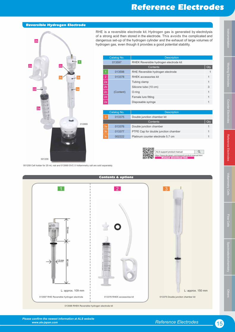
Reversible Hydrogen Electrode
RHE is a reversible electrode kit. Hydrogen gas is generated by electrolysis of a strong acid then stored in the electrode. This avoids the complicated and dangerous set-up of the hydrogen cylinder and the exhaust of large volumes of hydrogen gas, even though it provides a good potential stability.
Catalog No. Description013597 RHEK Reversible hydrogen electrode kit
Contents Qty1 013598 RHE Reversible hydrogen electrode 1
2 013378 RHEK accessories kit 1
2a
(Content)
Tubing clamp 1
2b Silicone tube (10 cm) 3
2c O-ring 1
2d Female lure fitting 1
2e Disposable syringe 1
Catalog No. Description3 013375 Double junction chamber kit
Contents Qty3a 013376 Double junction chamber 1
3b 013377 PTFE Cap for double junction chamber 1
3c 002222 Platinum counter electrode 5.7 cm 1
12a
2b
2d
2e
3a
3b3c
001209 Cell holder for 20 mL vial and 012669 SVC-3 Voltammetry cell are sold separately.
2c
001209
012669
Contents & options
1 2 3
013598 RHEK Reversible hydrogen electrode kit
013375 Double junction chamber kit013597 RHE Reversible hydrogen electrode 013378 RHEK accessories kit
L: approx. 150 mmL: approx. 109 mm
ALS support product manual
Manual download linkhttps://www.als-japan.com/support-product-manual.html

Reference Electrodes
Reference Electrodes
16Please confirm the newest information at ALS website www.als-japan.com
Cou
nter
Ele
ctro
des
Wor
king
Ele
ctro
des
Ref
eren
ce E
lect
rode
sVo
ltam
met
ry C
ells
Flow
Cel
lsO
ther
sSp
ectro
elec
troch
emis
tryIn
stru
men
tatio
n
If a purchased or self-assembled reference electrode is left in direct contact with air, the solution inside will evaporate and dry up gradually. In order to maintain the performance and life time of a reference electrode, it is recom-mended to store the electrode in a sealed preservative bottle with a solution similar to the reference electrode internal solution.
For example: 3 M NaCl for the preservation of the RE-1B Reference electrode.
012108
Sample Holder & Accessories
6 mm
012176
9 mm
012177
● 6 mm diameter holders can be used for RE-7 series reference electrodes● 9 mm diameter can be used in SVC-2 voltammetry cell ● Both can be used as a salt bridge, in which a reference electrode is installed in order to prevent contamination.
These products allow to perform electrochemical measurement with only 200μL sample volume. An IPPG* tip is attached to the end of a glass tube, so ionscan transmit freely. The sample holders are multi-purpose accessories.
Catalog No. Description011464 Ag/AgCl Ink for reference electrode (2.0 mL)
Specification
Surface resistance 0.2 Ω/sq/25.4 μm
Viscosity 50,000 ±10,000 CP @21.1 deg C
Flash point 82 deg C011464
Reference electrodes can be easily prepared by coating Ag/AgCl ink on the metal (Ag, Pt, Au, etc.) surface. The requirment is to deposit the Ag/ AgCl ink and wait for dry. The reference electrode prepared by Ag/AgCl ink is quite useful for IDA electrode measurements.
Catalog No. Description012796 Repair kit for Sample holder*
012796
*IPPG (Ion Permeability Porous Glass) is a porous glass with 40-200 Å diameter of pores. Chemically stable, operational as high as 800 °C. It can be cut with a sharp knife.
Reminder:Yellowish discoloration indicates contamination. This is caused by the absorption of organics into the pores from the air.
* Contents: Heat shrink Teflon tubing, 150 mm IPPG Rod, dia 3.2 x 4.0 mm, 10 pcs
L: approx. 68 mm L: approx. 68 mm
Preservative vial
Ag/AgCl Ink for Reference electrode
Catalog No. Description012176 Sample holder dia 6.0 mm (2 pcs)
012306 Sample holder dia 6.0 mm (22 pcs)
012177 Sample holder dia 9.0 mm (2 pcs)
012307 Sample holder dia 9.0 mm (22 pcs)
Catalog No. Description012108 RE-PV Preservative vial for reference electrode
Contents Qty011987 Teflon cap for RE-PV 1
------ Screw vial 10 mL 1Optional item
012549 RE-7 Electrolyte solution (10 mL)
Voltammetry Cells
Voltammetry Cells
17Please confirm the newest information at ALS website www.als-japan.com
Counter Electrodes
Working Electrodes
Reference Electrodes
Voltamm
etry Cells
Flow C
ellsO
thersSpectroelectrochem
istryInstrum
entation
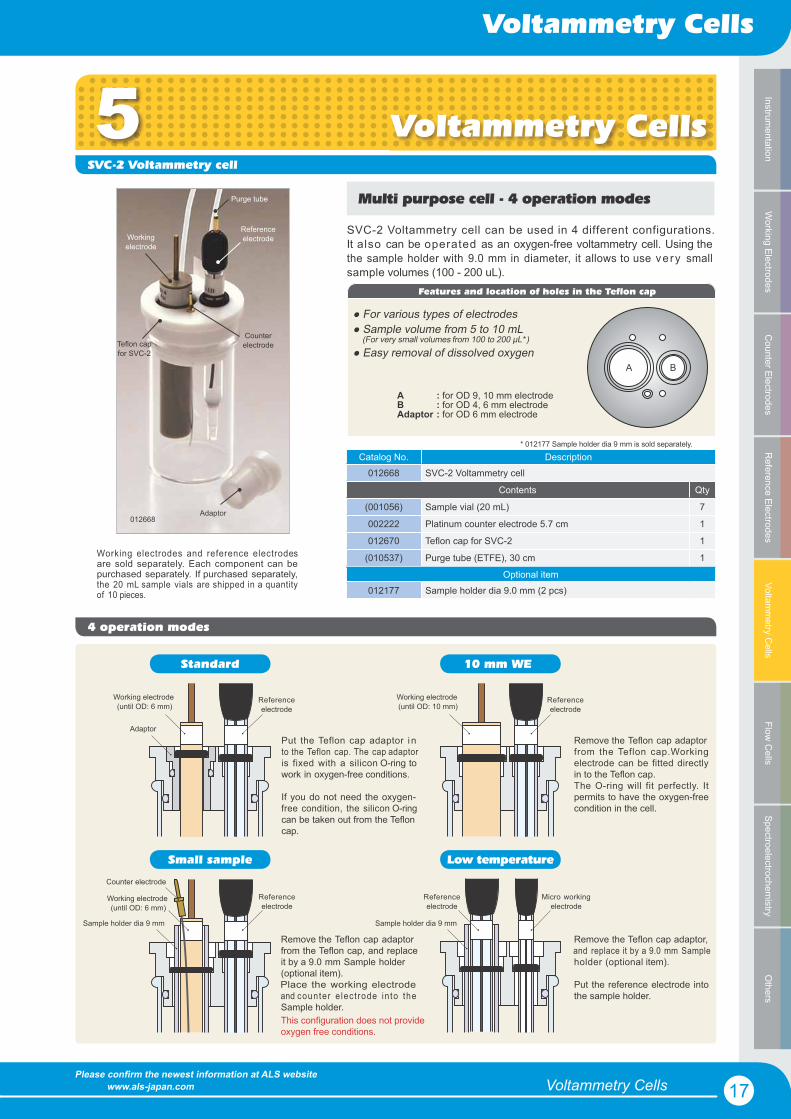
5SVC-2 Voltammetry cell
Catalog No. Description012668 SVC-2 Voltammetry cell
Contents Qty
(001056) Sample vial (20 mL) 7
002222 Platinum counter electrode 5.7 cm 1
012670 Teflon cap for SVC-2 1
(010537) Purge tube (ETFE), 30 cm 1Working electrodes and reference electrodes are sold separately. Each component can be purchased separately. If purchased separately, the 20 mL sample vials are shipped in a quantityof 10 pieces.
Multi purpose cell - 4 operation modes
Reference electrodeWorking
electrode
Counter electrode
Purge tube
012668
Teflon cap for SVC-2
Adaptor
Voltammetry Cells
Standard
Adaptor
Working electrode (until OD: 6 mm)
Reference electrode
Counter electrode
Sample holder dia 9 mm
Put the Teflon cap adaptor i n to the Teflon cap. The cap adaptor is fixed with a silicon O-ring to work in oxygen-free conditions.
If you do not need the oxygen-free condition, the silicon O-ringcan be taken out from the Teflon cap.
Remove the Teflon cap adaptor from the Teflon cap, and replace it by a 9.0 mm Sample holder (optional item).Place the working electrodeand counter e lect rode in to theSample holder.
Reference electrode
Working electrode (until OD: 6 mm)
This configuration does not provide oxygen free conditions.
Small sample
Micro working electrode
Remove the Teflon cap adaptor from the Teflon cap.Working electrode can be fitted directly in to the Teflon cap.The O-ring will fit perfectly. It permits to have the oxygen-free condition in the cell.
Remove the Teflon cap adaptor, and replace it by a 9.0 mm Sample holder (optional item).
Put the reference electrode into the sample holder.
Working electrode (until OD: 10 mm)
Reference electrode
Reference electrode
Sample holder dia 9 mm
10 mm WE
Low temperature
4 operation modes
SVC-2 Voltammetry cell can be used in 4 different configurations.It also can be operated as an oxygen-free voltammetry cell. Using thethe sample holder with 9.0 mm in diameter, it allows to use ve ry smallsample volumes (100 - 200 uL).
A B
Features and location of holes in the Teflon cap
ABAdaptor
: for OD 9, 10 mm electrode: for OD 4, 6 mm electrode: for OD 6 mm electrode
● For various types of electrodes● Sample volume from 5 to 10 mL (For very small volumes from 100 to 200 μL*)● Easy removal of dissolved oxygen
* 012177 Sample holder dia 9 mm is sold separately.
Optional item012177 Sample holder dia 9.0 mm (2 pcs)

Voltammetry Cells
Voltammetry Cells
18Please confirm the newest information at ALS website www.als-japan.com
Cou
nter
Ele
ctro
des
Wor
king
Ele
ctro
des
Ref
eren
ce E
lect
rode
sVo
ltam
met
ry C
ells
Flow
Cel
lsO
ther
sSp
ectro
elec
troch
emis
tryIn
stru
men
tatio
n
SVC-3 Voltammetry cell
A
B
A
Reference electrode is sold separately.
001197
Bulk Electrolysis cellPlate Material Evaluating cell
VC-4 Voltammetry cell
Catalog No. Description
012669 SVC-3 Voltammetry cell
Contents Qty
(001056) Sample vial (20 mL) 7
002233 Platinum counter electrode 5 cm 1
012671 Teflon cap for SVC-3 1
(010537) Purge tube (ETFE), 30 cm 1
Optional items
012961 Platinum counter electrode 23 cm
012963 Nickel counter electrode 23 cm
Catalog No. Description
001197 Bulk electrolysis cell
Contents Qty
012632 Sample vial (100 mL) 1
012961 Platinum counter electrode 23 cm 1
012551 Teflon cap (for bulk) 1
010530 Porous carbon electrode 1
001198 Lid for counter electrode 1
001196 Chamber for counter electrode 1
001236 O-ring for counter electrode 1
009131 Port plug 1
000178 Stirrer bar 1
(010537) Purge tube (ETFE), 30 cm 1
Catalog No. Description
011224 VC-4 Voltammetry cell
Contents Qty
(011504) Sample vial (5 mL) 7
002222 Platinum counter electrode 5.7 cm 1
011226 Teflon cap for VC-4 1
011227 Cell holder for 5 mL vial 1
(010537) Purge tube (ETFE), 30 cm 1
Catalog No. Description
011951 Plate Material Evaluating Cell
Contents Qty
Teflon Cell [Body] 1
Teflon Cell [Base] 1
Teflon cap 1
O-ring (Viton) 1
Screw 20 mm 2
002222 Platinum counter electrode 5.7 cm 1
(010537) Purge tube (ETFE), 30 cm 1
● Sample volume from 5 to 10 mL● For various types of electrodes● Easy removal of dissolved oxygen
● Sample volume from 1 to 3 mL● Including specific cell holder● Uses standard electrodes (6 mm)
This quite handy cell was developed in order to evaluate plate materials such as metal, semi-conducting materials, etc. For evaluation, a sample plate is sandwiched between the cell blocks.Reference electrode is
sold separately.
011951
012669 011224
This product is utilized for bulk electrolysis. The Carbon work- electrode is a reticulated form that prov ides suff ic ient surfacearea to attain the r equ i r ed ratefor electrolysis. A Water-jacketed cell and platinum mesh electrodes are available as optional items.
AB
: for OD 6 mm electrode: for OD 4, 6 mm electrode
A A
A : for OD 6 mm electrode
Optional items012022 O-ring for Plate Material Evaluating Cell, 10 pcs, Viton
012023 O-ring for Plate Material Evaluating Cell, 10 pcs, silicone
Optional items013580 Sample vial for alkaline solution (100 mL) (10 pcs)
012652 Water-Jacketed glass cell (100 mL)
002250 Platinum gauze electrode 80mesh
002251 Gold gauze electrode 100mesh
NEW

Voltammetry Cells
Voltammetry Cells
19Please confirm the newest information at ALS website www.als-japan.com
Counter Electrodes
Working Electrodes
Reference Electrodes
Voltamm
etry Cells
Flow C
ellsO
thersSpectroelectrochem
istryInstrum
entation
Catalog No. Description Vol (mL) OD (mm) ID (mm) Height (mm) Qty Purpose011504 Sample vial*1 5 18 15.6 30 10 VC-4
001056 Sample vial*1 20 28 25.6 50 10 SVC-2, SVC-3
012632 Sample vial*1 100 50 46.4 72 1 RRDE-3A, Bulk Electrolysis Cell
013580 Sample vial for alkaline solution*2 100 51.5 46.5 72 10 RRDE-3A, Bulk Electrolysis Cell
013581 Sample vial for alkaline solution*2 200 67 62 72 8 RRDE-3A, Bulk Electrolysis Cell
012672 Water-Jacketed glass cell 5 40 15.6 40 1 VC-4
001051 Water-Jacketed glass cell 20 55 25.6 50 1 SVC-2, SVC-3
012652 Water-Jacketed glass cell 100 70 46.4 80 1 RRDE-3A, Bulk Electrolysis Cell
013582 RRDE-3A Teflon cap (for 200 mL) 1 For 013581
001209 Cell holder for 20 mL vial 1 SVC-2, SVC-3
Cell Vials011504 001056 012632 012672
012652001051 001209
NEW
NEW
NEW
013580 013581 013582
*1 Hard glass for scientific research *2 Polymethyl pentene
● The tolerance of the dimensions is approximately ± 0.5 mm. ● The inner diameter (ID) is the size at the top.

Electrochemical Flow Cells
Flow Cells
20Please confirm the newest information at ALS website www.als-japan.com
Co
unte
r Ele
ctr
od
es
Wo
rkin
g E
lec
tro
de
sRe
fere
nce
Ele
ctr
od
es
Volta
mm
etr
y C
ells
Flo
w C
ells
Oth
ers
Spe
ctr
oe
lec
tro
che
mis
try
Inst
rum
ent
atio
n
001016009908
001002
Electrochemical Flow CellsOur working electrodes for flow cells are mounted in blocks of PEEK. This resin protects the electrodes from external noise and allows researchers to utilize them regardless the content of mobile phase of HPLC due to their hardness and organic solventresistance. Glassy carbon electrodes are usually chosen for the redox reaction studies in liquid chromatography. Platinum,Gold, Carbon paste, and Nickel electrodes are utilized for special purposes.
Catalog No. Description Size Purpose001000 Glassy carbon electrode (Dual 3 mm) 25 × 25 mm general redox measurements
001002 Gold electrode (Dual 3 mm) 25 × 25 mm measurement of thiol-related compounds
001012 Platinum electrode (Dual 3 mm) 25 × 25 mm measurement of hydrogen peroxide & oxidized substances
001008 Silver electrode (Dual 3 mm) 25 × 25 mm measurement of cyano-sulfide
001009 Nickel electrode (Dual 3 mm) 25 × 25 mm amino acids measurement by chemically modified electrode
001004 Carbon paste electrode (Dual 3 mm) 25 × 25 mm modified electrode measurement using carbon paste
001006 Glassy carbon / Gold electrode 25 × 25 mm others
012583 Glassy carbon / Platinum electrode 25 × 25 mm others
012124 Glassy carbon electrode (Single 3 mm) 25 × 25 mm general redox measurements
001016 Glassy carbon electrode (Single 6 mm) 25 × 25 mm general redox measurements
000999 PFCE Carbon electrode (Single 3 mm) 25 × 25 mm general redox measurements
011155 Gold electrode (Single 3 mm) 25 × 25 mm measurement of thiol-related compounds
009908 Platinum electrode (Single 3 mm) 25 × 25 mm measurement of hydrogen peroxide and oxidized substances
010251 Carbon paste electrode (Single 3 mm) 25 × 25 mm modified electrode measurement using carbon paste
The dual glassy carbon electrode is considered to be the standard working electrode for the cross flow cell. It is composed of two 3 mm glassy carbon electrodes placed in series. It can berotated 90 degrees and be used in parallel mode. The selectivity improves if a dual series electrode is used. In the parallel mode,identification of substances, from the different applied voltage response ratios, is possible.For the dual electrode, the electrode surface area doubles by using the jumper connector, and high sensitivity analysis becomes possible. As working electrode materials, Platinum, Gold and other materials are available.
Structure of the working electrodesingle/radial flow
dual, series/cross flow
dual, parallel/cross flow
i
i
i
E
E
E
T
T
T
E1
E1
E2
E1
E2002245 Jumper connector for dual electrodes
6 Flow Cells
Dua
lSi
ngle
Woriking electrodes for Flow cell
Features
� Excellent chemical resistance� Easy maintenance of the working electrode� Working electrode can be polished with PK-3 Polishing kit

Electrochemical Flow Cells
Flow Cells
21Please confirm the newest information at ALS website www.als-japan.com
Co
unter Ele
ctro
de
sW
orking
Elec
trod
es
Refe
renc
e Ele
ctro
de
sVo
ltam
me
try Ce
llsFlo
w C
ells
Othe
rsSp
ec
troe
lec
troc
hem
istryInstrum
enta
tion
Cross Flow Cell
Radial Flow Cell
Catalog No. Description012798 Cross Flow cell
Catalog No. Description012799 Radial Flow cell
The Cross Flow Cell is capable to measure concentrations down to 10 -15 mol/L using flow rates of 1 mL - 100 μL/min.
Rad ia l F low Ce l l i s deve loped fo r m ic robo re chromatography. Its detecting efficiency will improve when flow rates are 10 μL/min or lower. This flow cell consistsof thin layer electrodes and a symmetric design.
The wall-jet of analyte hits the surface of electrode,spreads in thin layer from the center to the perimeter ofthe electrode, resulting in enhanced sensitvity of themeasurement.
* Working electrode, Reference electrode and Gaskets are sold separately.
RE-3VT Reference electrodeCounter electrode
Working electrode
Gasket
RE-3VT Reference electrode
Counter electrode
Working electrode
Gasket
Schematic diagram of Cross flow cell
INLET OUTLET
gasket detector
Schematic diagram of Radial flow cell
gasket detector
INLETOUTLET
OUTLETflow channel
Optional items
* Working electrode, Reference electrode and Gaskets are sold separately.
Features
�����������������������#86��������9��;���<����������������������)������������������
Catalog No. Description013488 RE-3VT Reference electrode screw type (Ag/AgCl)
013489 RE-7VT Non Aqueous reference electrode screw type (Ag/Ag+)
001046 TG-2M Teflon Gasket (Cross Flow) / 12 μm (4 pcs)
001047 TG-5M Teflon Gasket (Cross Flow) / 25 μm (4 pcs)
001048 TG-6M Teflon Gasket (Cross Flow) / 50 μm (4 pcs)
012801 TG-8M Teflon Gasket (Cross Flow) / 100 μm (4 pcs)
001146 TG-2MR Teflon Gasket (Radial Flow) / 12 μm (4 pcs)
001147 TG-5MR Teflon Gasket (Radial Flow) / 25 μm (4 pcs)
001148 TG-6MR Teflon Gasket (Radial Flow) / 50 μm (4 pcs)
012802 TG-8MR Teflon Gasket (Radial Flow) / 100 μm (4 pcs)
002245 Jumper connector for dual electrodes
012912 0.04" Single lead connector (2 pcs)

QCM Flow Cells
QCM Flow Cells
22Please confirm the newest information at ALS website www.als-japan.com
Co
unte
r Ele
ctr
od
es
Wo
rkin
g E
lec
tro
de
sRe
fere
nce
Ele
ctr
od
es
Volta
mm
etr
y C
ells
Flo
w C
ells
Oth
ers
Spe
ctr
oe
lec
tro
che
mis
try
Inst
rum
ent
atio
n
The quartz crystal microbalance (QCM) technique, or coupling electrochemistry and crystal oscillation (eQCM), are very useful to de-termine compounds such as metal proteins, metal ions and thiol-conjugated oligonucleotides. The resonance frequency of the quartzcrystal changes when material attaches to the electrode’s surface. Using these cells allows sub-micro quantitative analysis usingthis unique behavior. For the best performance, use a degassed sample, to avoid bubbles and prevent temperature changes. TheQCM Flow cell can be used in two ways; by turning the blocks, it is possible to change from static mode to flow measurements.
QCM Flow cell mode EQCM mode
Flow cell; Batch cell; Cap; Flow cell holder; Pt counter electrode; Dynaseal PEEK; Fixing screws; Silicon O-ring; Teflon tube
Contents of QCM Flow cell
Inlet
Outlet
Quartz crystal
Reference electrode
Counter electrode
EQCM Flow Cells
The two blocks of the EQCM Flow cell are made from Polymethyl pentene.It gives a high resistivity for chemical compounds.As well as the QCM cell, this cell can be used in two ways. By turning the blocks over, it is possible to change from flow mode to static measurements.
Flow cell; Batch cell; Cap; Flow cell holder; Pt counter electrode; Stainless tube (Counter electrode for flow cell); Dynaseal PEEK; Fixing screws; Silicon O-ring; Teflon tube
Contents of EQCM Flow cell
OutletIntlet
ReferenceelectrodeCounter electrode
Quartz crystal
Combination of QCM and electrochemical measurements in an unique flow cell.
13.7 mm
5.1 mm
010226
Frequency: 7.995 MHz
Quartz crystal
QCM Flow Cells
ALS support product manual
Manual download linkhttps://www.als-japan.com/support-product-manual.html
ALS support product manual
Manual download linkhttps://www.als-japan.com/support-product-manual.html
Catalog No. Description013486 QCMT Flow cell kit
Optional items010226 Quartz crystal Au (5 pcs)
013447 Quartz crystal Pt (3 pcs)
012772 Blank Crystal with holder (5 pcs)
012167 RE-1B Reference electrode (Ag/AgCl)
012171 RE-7 Non Aqueous reference electrode (Ag/Ag+)
Catalog No. Description013487 EQCMT Flow cell kit
Optional items010226 Quartz crystal Au (5 pcs)
013447 Quartz crystal Pt (3 pcs)
012772 Blank Crystal with holder (5 pcs)
013488 RE-3VT Reference electrode screw type (Ag/AgCl)
013489 RE-7VT Non Aqueous reference electrode screw type (Ag/Ag+)

Spectroelectrochemical Batch System
Spectroelectrochemistry
23Please confirm the newest information at ALS website www.als-japan.com
Co
unter Ele
ctro
de
sW
orking
Elec
trod
es
Refe
renc
e Ele
ctro
de
sVo
ltam
me
try Ce
llsFlo
w C
ells
Othe
rsSp
ec
troe
lec
troc
hem
istryInstrum
enta
tion
7 Spectroelectrochemistry
SEC-C Thin Layer Quartz Glass Spectroelectrochemical cell Kit
Spectrometer
Applications
�� ���)�����������������������������������������������=��������� >������������������������������������������5��'������������������������������������������������������������������������ >�������������������������������������������8��������?�������������@���$���������%�������������������
Features
��T;�������������������������������������HJ!N�����X!J���Y��������������������;���Z!J�������������������������T;��������������;��[��������������H>�����8Y�������������������������������������
Set up
ALS Spectroelectrochemical setup
Setup introduction linkhttps://www.als-japan.com/1239.html
SEC-C Thin Layer Quartz Glass Spectroelectrochemical cell kit uses Platinum or Gold mesh electrodes as working electrodes. We offer 0.5 and 1.0 mm optical path length cells. Depending on the spectrometer used, the activity area for the cell is up toc6 mm in diameter with a center at 15 mm above of the bottom. The RE-1B or RE-7 are recommended to be used as reference electrodes.
SEC-C Thin Layer Quartz Glass Spectroelectrochemical cell kit
Spectroelectrochemical Batch System
7The aim of Spectroelectrochemistry (SEC) is the investigation of electrochemical reaction mechanisms and the interface betweenbetween electrolyte solution and electrode. Remarkable progress in this field and related technologies enable SEC to beapplied in wide areas. Nowadays, the relation between absorbance and potential for reversible or quasi-reversible systemsis theoretically elucidated. On this basis it is possible to the analyze electrochemical characteristics of a system, which would bedifficult based on a voltammogram only. A typical example is the redox enzyme cytochrome c and methylene blue.
Potentiostat Light Source

Spectroelectrochemical Batch System
Spectroelectrochemistry
24Please confirm the newest information at ALS website www.als-japan.com
Co
unte
r Ele
ctr
od
es
Wo
rkin
g E
lec
tro
de
sRe
fere
nce
Ele
ctr
od
es
Volta
mm
etr
y C
ells
Flo
w C
ells
Oth
ers
Spe
ctr
oe
lec
tro
che
mis
try
Inst
rum
ent
atio
n
Optical path length 1.0 mm cell
Catalog No. Description013510 SEC-C Thin Layer Quartz Glass Spectroelectrochemical cell Kit (Pt)
013511 SEC-C Thin Layer Quartz Glass Spectroelectrochemical cell Kit (Au)
Contents Qty
012906 SEC-C Pt counter electrode 1
013512 SEC-C Thin Layer Quartz Glass cell 1
011501 SEC-C Teflon cap 1
(010537) Purge tube (ETFE) 10 cm 1
Working Electrodes Qty
011498 SEC-C Pt Gauze working electrode for 013510 1
012017 SEC-C Au Gauze working electrode for 013511 1
Optional items
012167 RE-1B Reference electrode (Ag/AgCl)
012171 RE-7 Non Aqueous reference electrode (Ag/Ag+)
Types of working electrodes
Optical transmissionposition
12.5
6.512
Units: mm
1.0
12.5
5.512
Units: mm
0.5
* The lead wire of the mesh working electrode is covered with a PTFE shrinkage tube.
Optical path length 0.5 mm cell
Catalog No. Description012813 SEC-C05 Thin Layer Quartz Glass Spectroelectrochemical cell Kit (Pt)
012814 SEC-C05 Thin Layer Quartz Glass Spectroelectrochemical cell Kit (Au)
Contents Qty
012609 SEC-C05 Pt counter electrode 1
012815 SEC-C05 Thin Layer Quartz Glass cell 1
011501 SEC-C Teflon cap 1
(010537) Purge tube (ETFE) 10 cm 1
Working Electrodes Qty
012606 SEC-C05 Pt Gauze working electrode for 012813 1
012607 SEC-C05 Au Gauze working electrode for 012814 1
Optional items
012167 RE-1B Reference electrode (Ag/AgCl)
012171 RE-7 Non Aqueous reference electrode (Ag/Ag+)
012606012607
5
The optical path length 1.0 mm is most suitable for basic spectro- electrochemical measurements. Theoretically, it is possible to get the samesame result as with 0.5 mm cell using a sample with half of the concentration.
The optical path length 0.5 mm has a faster equilibration time than the 1.0 mm cell. The shorter time until stability is reached, makes it pos-sible to achive stable results for measurements in the high volatile organicsolvents and allows the detection of the unstable electrolysis products.
011498012017
6
Optical path length 1.0 mm cell
Optical path length 0.5 mm cell
* There is a specific working electrode for 0.5 mm optical path length. The working electrode for 1.0 mm optical path length can not be used in 0.5 mm optical path length quartz cell.
Types of working electrodes
Optical transmissionposition
* The lead wire of the mesh working electrode is covered with a PTFE shrinkage tube.
Schematic
Schematic
ALS support product manual
Manual download linkhttps://www.als-japan.com/support-product-manual.html
ALS support product manual
Manual download linkhttps://www.als-japan.com/support-product-manual.html

Spectroelectrochemical Batch System
Spectroelectrochemistry
25Please confirm the newest information at ALS website www.als-japan.com
Co
unter Ele
ctro
de
sW
orking
Elec
trod
es
Refe
renc
e Ele
ctro
de
sVo
ltam
me
try Ce
llsFlo
w C
ells
Othe
rsSp
ec
troe
lec
troc
hem
istryInstrum
enta
tion
Optical path length Merit Demerit
0.5 mm High electrolytic speed Difficult maintenance
1.0 mm Easy maintenance Slow electrolytic speed
UV-visible absorption spectrum and absorption changes during redox reaction can be obtained by using optically transparent Gold or Platinum mesh electrodes (OTE). Cyclic voltammetry and absorbance of the 2 mM potassium ferricyanide, as reference of the absorbance, performed in a SEC-C Thin Layer Quartz Glass Spectroelectrochemical cell are shown below (Figure 2-1, 2-2).
Simultaneous measurements of the cyclic voltammetry and absorbance as well as a constant potential electrolysis measurement were performed. The electrolysis, oxidation (Figure 3-1) and reduction (Figure 3-2), of the potassium ferrocyanide solution are shown below.
Fig.3-2. Absorbance changes for the reduction of the potassium ferricyanide.
Fig.3-1. Absorbance changes for the oxidation of the potassium ferrocyanide.
Fig.2-1. Cyclic voltammetry for 2 mM potassium ferricyanide. Fig.2-2. Absorption spectra of the electrolytic balance for 2 mM potassium ferricyanide electrolyzed at different potential.
Measurement example using cuvette type spectroelectrochemical cells
The comparison of 0.5 and 1.0 mm optical path length cells, sometimes shows a difference between theoretical and experimental values. This may be caused by theexperimental conditions and other reasons.
Comparison of 0.5 mm and 1.0 mm optical path length cells
A 2 mM potassium ferrocyanide (K4[Fe(CN)6]) was subject to an electrolysis reaction at 0.6 V until its equilibrium, and 1 M KNO3 solution was used as a reference. The oxidation reaction wasmonitored by the comparison of the absorbance change as a function of time at wavelengthsof 300 and 420 nm.
Fig.1-1. Absorbance for electrolysis performed with 0.5 mm optical path length cell
Fig.1-2. Absorbance for electrolysis performed with1.0 mm optical path length cell
The electrolysis time for the 0.5 mm optical path length cell is theoretically half of the one for the 1.0 mm cell. The opposite is true for the concentration, the same result for the 1.0 mm cell is possible for half of the concentration compared with the 0.5 mm cell. You can select the optical path length and the working electrode appropriate for your research purpose.
0.10 V0.15 V0.20 V0.25 V0.30 V0.40 V
300 nm
420 nm
0.3
0.25
0.2
0.15
0.1
0.05
0100 200 300 400 500 6000
Abso
rban
ce
Time [sec]
300 nm
420 nm
0.3
0.25
0.2
0.15
0.1
0.05
0100 200 300 400 500 6000
Abso
rban
ce
Time [sec]

Spectroelectrochemical Flow System
Spectroelectrochemistry
26Please confirm the newest information at ALS website www.als-japan.com
Co
unte
r Ele
ctr
od
es
Wo
rkin
g E
lec
tro
de
sRe
fere
nce
Ele
ctr
od
es
Volta
mm
etr
y C
ells
Flo
w C
ells
Oth
ers
Spe
ctr
oe
lec
tro
che
mis
try
Inst
rum
ent
atio
n
Optional items
Catalog No. Description012667 SEC-2F 400um Optical Fiber SR (25 cm)
012685 SEC-2F 400um Optical Fiber SR (2 m)
012234 UV/VIS Collimating Lens, 200-2000 nm
Catalog No. Description Thickness012661 SEC-2F S500 Silicone Gasket (4 pcs) 500 μm
012664 SEC-2F T500 Teflon Gasket (4 pcs) 500 μm
012665 SEC-2F T250 Teflon Gasket (4 pcs) 250 μm
012666 SEC-2F T100 Teflon Gasket (4 pcs) 100 μm
Catalog No. Description013488 RE-3VT Reference electrode screw type (Ag/AgCl)
013489 RE-7VT Non Aqueous reference electrode screw type (Ag/Ag+)
Spectroelectrochemical Flow SystemSEC-2F Spectroelectrochemical flow cell
Catalog No. Description012660 SEC-2F Spectroelectrochemical flow cell
Light source
Spectrometer
SEC-2F
Optical fiber
Computer
Inlet
Outlet
Reference electrodeSilicone gasket 500 μm
Working electrode
Counter electrode
Collimating Lens
1) Gasket 3) Reference electrode
4) Optical fiber2) The full list of the working electrodes are shown in the next page.
Features
��\���)�����������������������V���������;��[���������������������������������������������������������"���ype spectrometers
Using different gaskets, the spectroelectrochemical flow cell can be set up to different optical path lengths. We offer, as optional items,Silicon and Teflon gaskets with a 100, 250 and 500 μm of thickness. Flow injection analysis or stopped flow analysis is possible with this thin layer cell.
The SEC-2F can be connected to a variety of the optical fiber type spectrometer by using a collimating lens.
ALS Spectroelectrochemical setup
Setup introduction linkhttps://www.als-japan.com/1239.html
ALS SEC movie
Support Movie linkhttps://www.als-japan.com/support-sec.html
Potentiostat
Depending on your research topic you can select the working and reference electrodes. As working electrodes, we offer: ITO, Platinum, Gold, or Carbon grid electrodes. As reference electrodes: RE-3VT Reference electrode screw type (Ag/AgCl) and RE-7VT Non Aqueous reference electrode screw type (Ag/Ag+).
Diagram of the Spectroelectrochemical flow cellSet-Up

Spectroelectrochemical Electrodes
Spectroelectrochemistry
27Please confirm the newest information at ALS website www.als-japan.com
Co
unter Ele
ctro
de
sW
orking
Elec
trod
es
Refe
renc
e Ele
ctro
de
sVo
ltam
me
try Ce
llsFlo
w C
ells
Othe
rsSp
ec
troe
lec
troc
hem
istryInstrum
enta
tion
Comparison of the absorbance for different gasket thicknesses
The absorbance, at 420 nm, of the electrolysis of the potassium ferrocyanide as a function of time, was measured using gas-kets with 100, 250 and 500 μm thickness. Using the 100 μm gasket, the equilibrium was achieved in 40 seconds (Figure 4-1). The 250 μm gasket was used for the monitoring of the electrolysis spectrum of the vitamin B12 derivative complex (Figure 4-2).
Fig.4-1. Changes of the equilibrium time in different gasket thickness.
500 μm
250 μm
100 μm
Fig.4-2. Electrolysis spectrum change of Vitamin B12 derivative complex.
Grid Electrodes
ITO Optically transparent electrodes
ITO (Indium Tin Oxide) electrodes are very often used for spectroelectrochemical measurements. ITO electrodes transmit light in the visible range, but do not transmit light in ultraviolet range. The thickness of the ITO layer is 100 ± 10 nm, and the resis- tivity is 15 ± 1.5 Ω/sq*1.
013432
012656
27 mm
8 mm
27 mm
8 mm
Catalog No. Description Qty012655 SEC-2F Pt grid electrode for flow cell 1
012656 SEC-2F Au grid electrode for flow cell 1
012657 SEC-2F Carbon grid electrode for flow cell 1
Grid electrodes are produced by deposition of Platinum, Gold or Carbon onto quartz glass. The dimensions of the glass are 8 x 27 mm, with 1 mm thickness, and the grid lines are 100 μm in width with a distance of 150 μm between lines.
Schematic diagram of the grid
150 100
150100
Units: μm
*1. Manufacturer guarantee value. *2. Custom-made ITO electrodes are available on request.
Spectroelectrochemical Electrodes
The light transmittance was measured using ITO electrode and Gridelectrodes (Au, Pt and Carbon) on a quartz glass as reference. The ITOelectrode poorly transmits light in ultraviolet range. The transmittance isabout 10% at 280 nm of the wavelength. For wavelength above 400 nmthe transmittance is higher than 80%. Compared to quartz glass, the lighttransmission for grid electrode is about 30%, however it can be used inan ultraviolet range.
0.3
0.25
0.2
0.15
0.1
0.05
0
Abso
rban
ce
0.35
0.4
250 300 350 400 450
Wavelength [nm]
800500 550 600 650 700 750
269.5 sec
239.5 sec
209.5 sec
179.5 sec
149.5 sec
119.5 sec
69.5 sec
59.5 sec
29.5 sec
0.5 sec
ITO electrode
Grid electrode
Catalog No. Description013432 ITO11 electrode 8 x 27 x 1.1 mm (10 pcs)
013435 ITO05 electrode 8 x 27 x 0.5 mm (10 pcs)Others*2
013433 ITO11 electrode 10 x 10 x 1.1 mm (10 pcs)
013434 ITO11 electrode 10 x 20 x 1.1 mm (10 pcs)
013436 ITO05 electrode 10 x 10 x 0.5 mm (10 pcs)
013437 ITO05 electrode 10 x 20 x 0.5 mm (10 pcs)
Reference data:The light transmittance is 50 – 55% for SEC-C Platinum mesh electrode.

PK-3 Electrode Polishing kit
Others
28Please confirm the newest information at ALS website www.als-japan.com
Co
unte
r Ele
ctr
od
es
Wo
rkin
g E
lec
tro
de
sRe
fere
nce
Ele
ctr
od
es
Volta
mm
etr
y C
ells
Flo
w C
ells
Oth
ers
Spe
ctr
oe
lec
tro
che
mis
try
Inst
rum
ent
atio
n
PK-3 Electrode Polishing Kit
Instructions to polish the working electrode surface with PK-3
Prepare the glass plate, and put a few drops of polishing diamond on diamond polishing pad.
Hold the CV electrode at right angle to the pad. Polish in a circular motion, for 30 seconds to 2 minutes. Rinse the electrode surface with distilled water.
The purpose of polishing is to remove redox reaction products accumulated on the working electrode surface. The polishing maintains the working electrodes for CV/Flow cells and keeps them in a good condition.
With repeated electrochemical redox reaction experiments, adhesion of experimental products on the electrode surface can take place and the electron transfer rate is attenuated gradually. If electron transfer speed becomes slow, the difference bet- ween peak potentials for oxidation and reduction will broaden.
After refreshing the electrode surface by polishing, the electron transfer rate will increase again. As a result, the peak potential difference reduces and returns to an ideal CV.
* When emery paper is used for polishing, use distillated water only. Polishing alumina and diamond cannot the used for Pyrolytic graphite electrode (PGE) and Plastic formed carbon electrode (PFCE).
8 Others
Polishing refreshes working electrodes response
after polish
before polish
Glassy Carbon electrode
STEP 1 STEP 2 STEP 3
Catalog No. Description013223 PK-3 Electrode Polishing kit
Contents Qty Purpose012620 0.05 μm polishing alumina (20 mL) 1 For final polishing
012621 1 μm polishing diamond (10 mL) 1 For intermediate polishing
(012600) Alumina polishing pad 10 For final polishing
(012601) Diamond polishing pad 10 For intermediate polishing
013222 Replacement glass plate for PK-3 1 Glass plate to stick the polish padOptional items Purpose
013234 6 μm polishing diamond (10 mL) For rough polishing
012600 Alumina polishing pad (20 pcs) For final polishing
012601 Diamond polishing pad (20 pcs) For intermediate polishing
012610 Coarse polishing pad (20 pcs) For rough polishing
012611 Emery paper UF800* (20 pcs) For PG and PFCE electrode polishing
ALS PK-3 movie
Support Movie linkhttps://www.als-japan.com/1634.html

Glassy Carbon
Others
29Please confirm the newest information at ALS website www.als-japan.com
Co
unter Ele
ctro
de
sW
orking
Elec
trod
es
Refe
renc
e Ele
ctro
de
sVo
ltam
me
try Ce
llsFlo
w C
ells
Othe
rsSp
ec
troe
lec
troc
hem
istryInstrum
enta
tion
Glassy Carbon
We supply a broard range of Glassy Carbon products. Special shapes such as pipes, pot shape etc. or custom sizing are available on request.
Glassy Carbon has a quite unique structure. This material con-tains a random combination of basal planes and edge planes. The schematic at the right shows a model illustration introducedby G. M. Jenkins and K. Kawamura. GC is an outstanding material, which can be used for the electrodes in analytical chemistry, for electrochemical measurements, detection of high- speed liquid chromatography, biosensors and others.
La: Intraplanar Microcrystaline Size, Lc: Interplanar Microcrystaline SizeG.M. Jenkins and K. Kawamura: Nature 231,175 (1971).
Characteristics of Glassy Carbon
Rod type: diameter, from 1 to 10 mm; length up to 800 mmPlate type: up to 300 x 300 mm; thickness of 0.3, 0.5, and 1 to 6 mmFilm type: up to 100 x 100 mm; thickness of 60, 100, 140 and 180 μmFurthermore, drilling, cutting, and mirror polishing is possible.
Size range available for customized product
Physical probertyShape Other than Film FilmDensity 1.42 g/cm3 1.54 g/cm3
Ash content < 100 ppm
Upper Temparature Limit in vacuum 3000 deg C 1000 deg C
Porosity 0 %
Gas Transmission Rate 10-9cm2/s 10-11cm2/s
Hardness 230 HV1 340 HV1
Bending Strength 260 N/mm2 210 N/mm2
Compressive Strength 480 N/mm2 580 N/mm2
Young's Modulus 35 kN/mm2
Thermal Expansion Coefficient (20 - 200 deg C) 2.6×10⁻⁶ 1/K 3.5×10⁻⁶ 1/K
Heat Conducting (30 deg C) 6.3 W/(m•K) 4.3 W/(m•K)
Electrical resistivity 45 μΩ•m 50 μΩ•m
Features
��#���)���������=�ellen��������as ���� as a�3,000 ��� C �� v����m ��#������������������������������������������]����������������������'������������"�������������5�s��������7���������������������������������������9��������������������������������������6�;���������=���������#�����������������������������������������������������7������)�������������]����������������5������������������
Catalog No. Description SizeRod type
010761 R-1 Glassy carbon rod dia 1 x 100 mm
010762 R-2 Glassy carbon rod dia 2 x 100 mm
010763 R-3 Glassy carbon rod dia 3 x 100 mmPlate type
012825 P-1 Glassy carbon plate 10 x 10 x 1 mm
012086 P-1 Glassy carbon plate 25 x 25 x 1 mm
012087 P-2 Glassy carbon plate 25 x 25 x 2 mm
012088 P-3 Glassy carbon plate 25 x 25 x 3 mmFilm type
012089 F-100 Glassy carbon film 25 x 25 x 0.1 mmPowder type (Spherical)
012090 S-12 Glassy carbon powder 0.4 - 12 μm, 10 g
012091 S-20 Glassy carbon powder 10 - 20 μm, 10 g

Rev. June/2017For All ElectrochemistsPresented by ALS Co., Ltd. & BAS Inc.
www.als-japan.com
Local distributor:
https://www.als-japan.com/
Manufacturered by:
ALS Co., LtdExclusive distributor:
BAS Inc.1-28-12, Mukojima, Sumida-ku, Tokyo 131-0033, JAPANAdress:
Phone: +81-3-3624-0367 Fax: +81-3-3624-0940URL:Email: [email protected]
ALS Co., Ltd is a member of BAS Inc.
BAS Inc. is close to "TOKYO SKYTREE".BAS Inc. is close to "TOKYO SKYTREE".
Peter-Henlein-Str. 20D-85540 Haar b. MünchenTelefon 089/45 60 06 70Telefax 089/45 60 06 [email protected]
C3 PROZESS- UNDANALYSENTECHNIK GmbH