
Product Lifecycle Management
15
Product Lifecycle Management Activity Modelling – Engineering Design David Coombes 09MMP300
-
Upload
david-coombes -
Category
Documents
-
view
235 -
download
0
description
PLM - Coursework
Transcript of Product Lifecycle Management
Product Lifecycle Management
Activity Modelling – Engineering Design
David Coombes
09MMP300
P r o d u c t L i f e c y c l e M a n a g e m e n t D e s i g n A c t i v i t y
2 | P a g e D a v i d C o o m b e s – A 9 1 1 6 5 2
Contents Section A ................................................................................................................................................. 4
1. Identify the viewpoint from which the model is being composed. ............................................ 4
2. Produce 3 activity diagrams ........................................................................................................ 5
3. Describe the key activities in the model ..................................................................................... 8
A0 – Design and Manufacture of a CNC component ...................................................................... 8
A1 – Design of a CNC component ................................................................................................... 8
A2 – Manufacture of a CNC component ......................................................................................... 8
A11 – Produce Project Brief ............................................................................................................ 9
A12 – Initial Research ...................................................................................................................... 9
A13 – Produce P.D.S ........................................................................................................................ 9
A14 – Initial Designs ........................................................................................................................ 9
A15 – Validate Designs .................................................................................................................. 10
A16 – Final Design ......................................................................................................................... 10
4. Provide one page of example information flow descriptions ................................................... 10
Customer ....................................................................................................................................... 10
Customer Requirements ............................................................................................................... 10
Design Knowledge ......................................................................................................................... 10
Drawing Standards ........................................................................................................................ 10
Final Drawings ............................................................................................................................... 10
Finished Component ..................................................................................................................... 10
Machine ........................................................................................................................................ 10
Operator ........................................................................................................................................ 11
P.D.S .............................................................................................................................................. 11
Part Program ................................................................................................................................. 11
Patents .......................................................................................................................................... 11
Process Limitations ....................................................................................................................... 11
Time Limit...................................................................................................................................... 11
Tooling........................................................................................................................................... 11
Workpiece ..................................................................................................................................... 11
5. Highlight any significant issues with the model ........................................................................ 11
Section B ............................................................................................................................................... 12
Value ................................................................................................................................................. 12
Advantages ........................................................................................................................................ 12

P r o d u c t L i f e c y c l e M a n a g e m e n t D e s i g n A c t i v i t y
3 | P a g e D a v i d C o o m b e s – A 9 1 1 6 5 2
Limitations ........................................................................................................................................ 12
Section C ............................................................................................................................................... 13
IDEF3 ................................................................................................................................................. 13
UML ................................................................................................................................................... 13
EXPRESS ............................................................................................................................................. 14
Bibliography .......................................................................................................................................... 15

P r o d u c t L i f e c y c l e M a n a g e m e n t D e s i g n A c t i v i t y
4 | P a g e D a v i d C o o m b e s – A 9 1 1 6 5 2
Section A – Build and IDEF0 model to include;
1. Identify the viewpoint from which the model is being composed.
Every IDEF0 model needs a purpose and viewpoint statement. Accompanying the A0 node comes
the reasoning and the perspective, which help to guide and constrain the creation of the model. The
purpose part of the statement embodies the reason why the model was created. Each model will
have a purpose; this determines the structure of the model and ascertains the communication goal
for the model. The viewpoint indicates the perspective in which the information can be seen. This
information can take a different meaning if a different perspective taken to view the model, this
indicates a need for a different, single model for every viewpoint required to be assessed.
For the following diagrams;
The purpose of the model is to assess the design and manufacture stages within the development of
a CNC component. This is taken from the viewpoint of the design team involved with the
development of the CNC component in question.
P r o d u c t L i f e c y c l e M a n a g e m e n t D e s i g n A c t i v i t y
5 | P a g e D a v i d C o o m b e s – A 9 1 1 6 5 2
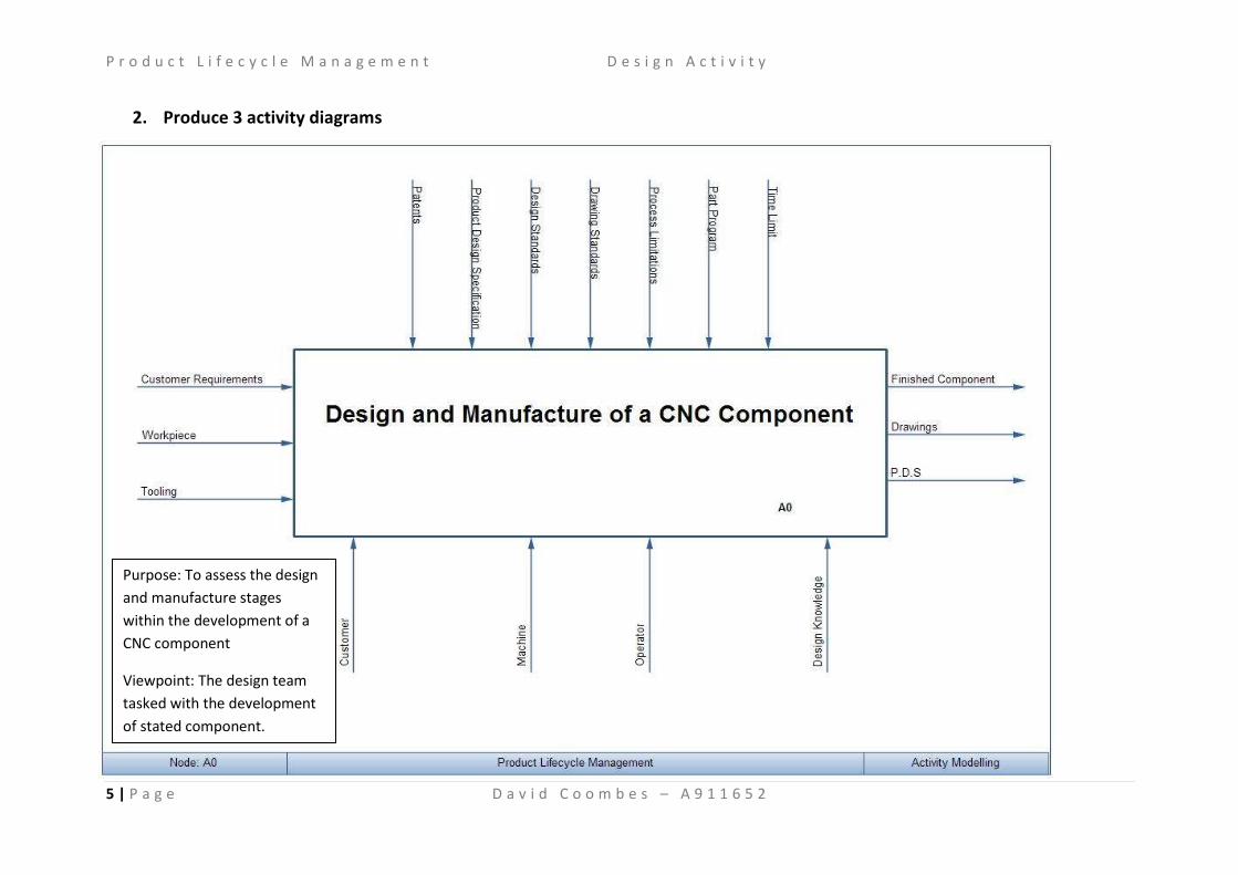
2. Produce 3 activity diagrams
Purpose: To assess the design
and manufacture stages
within the development of a
CNC component
Viewpoint: The design team
tasked with the development
of stated component.
P r o d u c t L i f e c y c l e M a n a g e m e n t D e s i g n A c t i v i t y
6 | P a g e D a v i d C o o m b e s – A 9 1 1 6 5 2
P r o d u c t L i f e c y c l e M a n a g e m e n t D e s i g n A c t i v i t y
7 | P a g e D a v i d C o o m b e s – A 9 1 1 6 5 2
P r o d u c t L i f e c y c l e M a n a g e m e n t D e s i g n A c t i v i t y
8 | P a g e D a v i d C o o m b e s – A 9 1 1 6 5 2
3. Describe the key activities in the model Accompanying each activity is a description that gives details to the processes required to complete
the activity. This is potentially expanded further by the completion of a decomposition of the
activity.
A0 – Design and Manufacture of a CNC component
This activity encompasses all activities concerned with the design and manufacture of any consumer
required CNC component. This includes all design and manufacturing issues, ranging from evolving a
project brief to completing the manufacture of the product. The inputs related to the design aspect
are from external sources. This reduces the control that the organisation has. In contrary, the
outputs are intended for the use of the enterprise or the customer only. There are no other external
sources that can complicate the outputs from this activity. The activity is expanded in A1.
The main input related directly to design is one that comes from the customer. This is the
information given by the customer, specifying details about the final product. Other inputs involve
the manufacturing side of the activity. Workpiece consists of the blank material that is manufactured
into a completed component. The manufacturing process will directly transform this input into the
output of a completed component.
Controls within the design come mainly in the form of standards and restrictions in the way the
design is completed. The part program is the main control within manufacturing and governs the
way in which the part is produced.
The customer themselves, can be seen as mechanism, where are their requirements are an input.
This is the means by which the activity is performed. The machine and the operator undertaken the
manufacturing task and design knowledge is important when performing most design activities.
Alongside the output of the completed component are results from the design of the component. A
completed PDS can be seen as an output along with finalised drawings. These documents can be
used to aid a similar project.
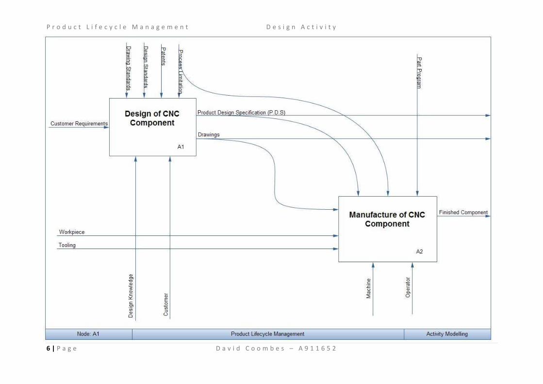
A1 – Design of a CNC component
This design activity embraces all aspects related to designing a new component. This includes the
identification of needs and combines them into a marketable product. This potentially marketable
product is further developed and eventually put into manufacture. This activity is expanded in A11
The only input comes from an external source, customer requirements, and initiates the whole
process. The controls are manly rules and regulations associated with design of any product. Design
knowledge is the most important mechanism and influences design significantly. The output from
the design process; drawing and a completed PDS, are both a final output but also information
needed to complete the manufacturing stage.
A2 – Manufacture of a CNC component
The second design activity within the first decomposition relates to all aspects considered when
manufacturing a component. This defines the process of making the product, turning the stock
material into a usable product. This includes; all equipment essential, skills required, resources
needed and the quality assurances necessary for a successfully manufactured product.
P r o d u c t L i f e c y c l e M a n a g e m e n t D e s i g n A c t i v i t y
9 | P a g e D a v i d C o o m b e s – A 9 1 1 6 5 2
Both of the outputs from the design stage are included within the manufacture of the product. The
completed PDS is used as controlling action throughout the manufacturing stage. Whereas the
drawings produced from the design stage can be used as a direct input from the design stage. The
part programme which controls the activity is shown. The machine and operator are the resources
used when producing the part, therefore are shown as mechanisms and the output of a finished
component is indicated.
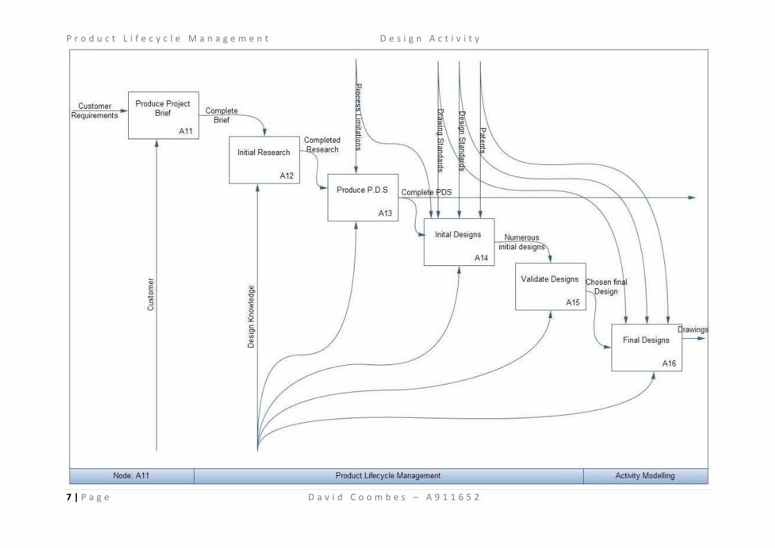
A11 – Produce Project Brief
The first stage within any design process is to complete a project brief; this will be comprised using
information received from the customer requirements. This product brief will give brief details to
the needs of the product and what should be achieved once the product is finally produced. It
should be possible to determine all areas of research from the product brief.
A12 – Initial Research
This is where all information is gathered relating to any aspect of the final product. This will consist
of researching into existing products, the usage of the product in service and information regarding
to the materials and processes used. This will provide all the information required to complete the
design process successfully.
The completed project brief will control the activity, giving a lead to all areas that need researching.
Design knowledge will assist the research progress. The inherent knowledge of materials and
processes will reduce the time taken throughout the research phase.
A13 – Produce P.D.S
Product design specification is vital to any design process, is constrains the designs that follow. It
ensures that all designs meet the product need, without being un-marketable and un-producible.
The PDS can continue to be edited throughout the design stages, some designs may throw up
ambiguities within the specification.
The completed research will act as the input of the production of the product design specification.
This research will aid the characterization of numerous items including; price, size, weight,
functionality, production methods, quality assurance and many others. Process limitations will
control the production of the specification; it will constrain the design at subsequent stages also.
Again design knowledge will be the means by which the PDS is created.
A14 – Initial Designs
By using the PDS an input initial designs will be developed. This process will consist of a
brainstorming of all ideas. This almost exhausted list will be developed and the final design chosen
from the catalogue of initial ideas.
Design knowledge, including creativity will again be the mechanism within this activity. There will be
numerous controls, helping the limit and channel the designs. Initially any patents, hopefully
uncovered within the research phase, will need to be considered. These patents cannot be
encroached on. Following this, design and drawing standards will need to be adhered to. These
standards ensure the uniformity of products information throughout the design stage. This will
enable people from outside of the design process to understand the drawing.
P r o d u c t L i f e c y c l e M a n a g e m e n t D e s i g n A c t i v i t y
10 | P a g e D a v i d C o o m b e s – A 9 1 1 6 5 2
A15 – Validate Designs
From the hopefully large list of initial designs, a process is needed to reduce these down, in order to
produce a final design. This final design will be developed within the validation and again afterwards.
This selection process can be completed by numerous methods, one of which is a design matrix. This
assesses each individual design related to part of the specification, the design scored on each of
these items and the best score indicates which the best design is.
The design knowledge and opinions on the quality of the designs are the main other information
needed to complete this activity.
A16 – Final Design
Once the final design has been the selected, the activity is to develop it and to produce technical
drawings and all the information required to manufacture the component.
The input will be the information gained whilst validating the designs in the previous stage. As with
the generation of initial ideas the controls and mechanisms will be identical. Restrictions such as
standards for drawings and existing patents will need to be adhered to. The design knowledge of the
restrictions stated will aid the development of this activity and the production of the require output.
4. Provide one page of example information flow descriptions
Customer
Mechanism – This is the source of the information which initiates the whole design process. This is
also the source, if any more information is required and aids the project brief activity mainly.
Customer Requirements
Input – The information gained from the customer which initiates the whole process and is the
reason for completing the task. Indicates the needs of the user.
Design Knowledge
Mechanism – This is the knowledge from the designer that may aid the process. This includes;
knowledge of the manufacturing process, the drawing standards and initial knowledge of the
component.
Drawing Standards
Control – Conforming to BS 8888 will ensure the drawings can be understood by other people
outside the organisation.
Final Drawings
Output –The final drawings will be a physical output of the design process, these will be used
throughout the manufacturing stage but will still be a physical output once the process is complete.
Finished Component
Output – The needs of the customer should be satisfied within the final component. All acts within
the process are targeted at producing the final component.
Machine
Mechanism – The means by which the final product will be produced.
P r o d u c t L i f e c y c l e M a n a g e m e n t D e s i g n A c t i v i t y
11 | P a g e D a v i d C o o m b e s – A 9 1 1 6 5 2
Operator
Mechanism – The operator will run the machine and ensure the machine is working, and can
complete the manufacturing process.
P.D.S
Output – The product design specification is the result of all the research within the design stage.
This will be a physical output, in the form of a document. It will also act as a guide for a lot of the
designs.
Part Program
Control – This will control the machine, and ensure the part produced is what is required.
Patents
Control – If there are any existing products in the market, there are potential patents in force,
prohibiting certain designs from being sent to market.
Process Limitations
Control – Every manufacturing process will have certain limitations, these can be avoided by
considering the process within the design stage.
Time Limit
Control – The customer will require the component within a certain time limit. This will control the
amount of time spent at each stage throughout the process.
Tooling
Input – The tooling within the machine will do the actual production. These are expendable items
which will get used up within the manufacturing process.
Workpiece
Input – This blank of material will eventually become the finished component.
5. Highlight any significant issues with the model
There are many issues within IDEF0 modelling. Some of which can be overcome, others have been
overcome using different methods of activity modelling.
Within the diagram above, the research and PDS activity will be continuous processes. The model
indicates that once these have been completed they are forgotten and never considered again. This
is not the case. The research will continue throughout the design process, especially when
innovative designs are put forward. The PDS can be altered, flaws within the PDS can be highlighted
at the design stage, and the PDS will need altering then.
Design knowledge is also a very broad area, and to be combined under one mechanism results in it
influencing numerous activities within the design process. This mechanism could easily be
decomposed into a number of different aspects. The consequence of this would be that more
mechanisms would be included but they would individually influence fewer activities, thus resulting
in less confusing within the model.
P r o d u c t L i f e c y c l e M a n a g e m e n t D e s i g n A c t i v i t y
12 | P a g e D a v i d C o o m b e s – A 9 1 1 6 5 2
Section B – From the results, comment briefly on the value of the model produced. Explaining
both the advantages and the limitations of the IDEF0 approach
Value
There are numerous values associated with any IDEF0 model. One of the main uses of the model is
to help organise the analysis of a system. Within the example model above the design and
manufacture of a CNC component individual activities can be seen significantly easier and the
organised nature means the analysis of the process is more straightforward to complete. Along with
this, good communication between all aspects of the process is encouraged. This heightened level of
communication produces a process which ultimately runs smoother and more effectively.
Advantages
One of the first main advantages is that it is a well documented technique. This leads way to a highly
standardised way of working, and way of producing the model. This in turn can reduce confusion
and mean it is easier for people from outside the process to understand the activities and the flow.
The formal method of categorizing the inputs, outputs, mechanisms and controls supports this ease
of understanding. To compliment the broad use of the IDEF0 modelling technique, there are a
number of tools that can be used to aid the production of a diagram.
The process is a simple one, and a user can be taught how to create a model in a very short space of
time. This ease of learning makes this type of modelling very popular and increases the areas of use.
IDEF0 modelling also provides a controlled manner in how the information is broken down, this
means that any one of the design process, the activities can be scrutinised and any anomalies can be
rectified easily. These more detailed views, can give a better insight into the design process and also
into the product of itself.
Changes within an organisation are regularly needed; these changes occasionally need to link with
changes in the process flow. By viewing the activities and the organisation separately it is easier to
visualise the changes that potentially could take place.
Limitations
One problem with the IDEF0 model is its inclination to represent the activities in a sequence even if
the processes activities are not necessarily completed in a sequence. With the activity boxes flowing
from top left to bottom right, it is simple to see the diagram as a sequence. If an output from one
activity is seen as an input to the next, this sequence assumption can be easily made.
Problems can arise within the modelling when it comes to considering multiple activities at any one
time. It is difficult to describe more than one activity at any one time; this again leads to the
sequential view.
Another issue can come in decision making within the model, this is to decide what aspects are a
considered an activity within the diagram or as part of the decomposed model afterwards. This is an
opinion and is decided by the creator of the model. Certain aspects of the model can be grouped
under a single heading; this would mean that a further decomposed model would be required. If this
decomposition only consists of two activities there could be possibility to combine these activities
P r o d u c t L i f e c y c l e M a n a g e m e n t D e s i g n A c t i v i t y
13 | P a g e D a v i d C o o m b e s – A 9 1 1 6 5 2
into the model above. This is an opinion of the models creator, and could be interpreted a different
way by someone else looking at the model.
Difficulties can arise within the IDEF0 models due to the concise nature of the flows and activity
boxes. This means ambiguities within the meaning of some of these statements can cause confusion
within the meanings. This is overcome by the list of information flow descriptions. This provides
excessive work but reduces the confusion within the understanding of the model.
Section C – Identify and discuss the value of other competitive or complementary methods which
might be used when configuring a PLM system to support an engineering design department or any
other business activity concerned with product lifecycle.
There are numerous ways of activity modelling available that can complement the IDEF0 technique,
but equally as numerous are the quantity of methods that are seen as competition to the IDEF0
approach. These include;
IDEF3
IDEF3 is a progression from IDEF0 and deals with some of the problems encountered when using
IDEF0. Rather than IDEF0 having activities modelled, with; inputs, outputs, controls and mechanisms,
IDEF3 concentrates around the processes. The sequences of activities are comprised by three main
aspects; process-centred diagrams, object-centred diagrams and elaboration forms. The IDEF3
model can be utilised to model numerous processes. This includes modelling a current business
system or process, modelling a proposed system or process and developing a model of the process
or system from different viewpoints. There are two different views developed within IDEF3
modelling. The first is Process Flow Description (PFD); this describes the how the process works.
Secondly there is The Object State Transition Description (OSTD), which portrays the alterations an
object makes during the process. To fully describe a system, these two descriptions are used
together. These individually describe a different part of the whole process. Many of the advantages
seen within IDEF0 are also continued through into IDEF3. These include; the high level of
documentation, simplistic model and controlled manner in how the information is broken down.
Alongside these advantages, others can be seen that are not common with IDEF0. Firstly it allows an
easy mechanism for capturing process information. This is slightly different to that of IDEF0, where
IDEF0 provides a good tool for process design, IDEF3 concentrates on the process information.
Depending on the requirements of the model, as selection process between to two will need to take
place. IDEF3 provides an excellent chronological view upon the whole process. This allows easy
definition of all relationships and indicates easily if a proposed process is realistic. IDEF3 finds it
difficult to handle unexpected circumstances. Especially when models are created for existing
processes, the model cannot adjust when unforeseen events are introduced into the workflow.
Further to this, IDEF3 finds it difficult to identify problems which are hidden within multiple tasks,
due to the behaviour of each object creating the workflow.
UML
Unified Modelling Language (UML) is a general purpose modelling language created by the object
management group. The Unified Modelling Language (UML) is used to define, envisage, adjust,
construct and document the substance of an object-oriented software intensive system under
development. UML can be applied to all processes and throughout the development lifecycle. The
P r o d u c t L i f e c y c l e M a n a g e m e n t D e s i g n A c t i v i t y
14 | P a g e D a v i d C o o m b e s – A 9 1 1 6 5 2
modelling language can also be applied to numerous technologies. There have been methods to
improve the language, this has happened in the form of revisions to the language, with UML 2 being
the most updated revision. By using this object orientated approach, it is easier to model the way
real world entities behave. It also uses a modular approach, producing objects that can be
constructed independently to other objects. There is a need to define between the UML model and
the set of diagrams of a system. UML diagrams represent two different views of a system model.
These are static and dynamic. The static diagrams highlight the physical objects and the attributes
within a system, whereas dynamic diagrams show behaviours and calibrations amongst objects
within the system. One of the advantages of UML is the ability is for it to model just about any type
of application, running on any type and combination of hardware, operating system, programming
language, and network, in UML. This gives an incredibly large number of areas in which this
modelling technique can be applied. Another advantage is that the model is produced in a natural
way and Transactional, Real-time, and Fault-Tolerant systems can be modelled in a specific way.
Finally the effectiveness to model large, complex, activities makes it a very suitable for a number of
applications. One of the issues that face creators of a UML documents is that there is no specific
standardised file format. This results in individual vendors providing a program which produces
models that are not interchangeable between different software. Even though it is effective at
producing large and complex models, these models are not easy to complete. There is a very high
level of understanding needed to create a large complex model.
EXPRESS
EXPRESS modelling language is a data modelling language for product data. EXPRESS is formalized in
the ISO Standard for the Exchange of Product model STEP (ISO 10303), and standardized as ISO
10303-11. It is used to model entity types. This model can be defined in 2 ways, textually and
graphically. Textually can be seen as the most important; with inputs coming in the form of an ASCII
file. Graphical representation is more user-friendly and easier to understand. One of the advantages
that EXPRESS modelling has is the standards attached to it. This standardised form means that a
single method of producing models is adhered to by all, reducing the confusion when interpreting
other models. Also by using EXPRESS-G the model can be represented in a more understanding way,
making the model ultimately easier to use. The problem with EXPRESS-G notation is that it struggles
to formally specify complex constraints.
P r o d u c t L i f e c y c l e M a n a g e m e n t D e s i g n A c t i v i t y
15 | P a g e D a v i d C o o m b e s – A 9 1 1 6 5 2
Bibliography Dorador, J. M., & Young, R. I. (2000). Application of IDEF0, IDEF3 and UML methodologies in the
creation of information models. International Journal of Computer Integrated Manufacturing , 430-
445.
Feldmann, C. G. (1998). The practical guide to business process reengineering using IDEF0. New York,
NY, USA : Dorset House Publishing Co., Inc. .
Kappes, S. (1997). Putting your IDEF0 model to work. Business Process Management Journal , 151-
161.
Rumbaugh, J., Jacobson, I., & Booch, G. (2004). Unified Modeling Language Reference Manual, The
(2nd Edition). Pearson Higher Education .
Rumbaugh, J., Jacobson, I., & Booch, G. (2005). Unified Modeling Language User Guide, The (2nd
Edition). Addison-Wesley Professional .
Schenck, D. A., & Wilson, P. R. (1994). Information modeling: the EXPRESS way. New York: Oxford
University Press.
Whitman, L., Huff, B., & Presley, A. (1997). Structured models and dynamic systems analysis: the
integration of the IDEF0/IDEF3 modeling methods and discrete event simulation. Winter Simulation
Conference (pp. 518 - 524 ). Atlanta, Georgia, United States : IEEE Computer Society .