
PRODUCT INSTRUCTIONS - robs-mw.com · RMW-0302-Manual_Straddle_Carrier-EN-v0.3.doc Page 1 of 34...
34
RMW-0302-Manual_Straddle_Carrier-EN-v0.3.doc Page 1 of 34 PRODUCT INSTRUCTIONS Thanks for purchasing this product from RMW. In this manual you find all the information you need to assemble and paint the model. PRODUCT DESCRIPTION Container straddle carrier Product No: 0302 A straddle carrier is a non-road going vehicle for use in port terminals and intermodal yards used for stacking and moving ISO standard containers. Straddles pick and carry containers while straddling their load and connecting to the top lifting points via a container spreader. These machines have the ability to stack containers up to 4 high. These are capable of relatively low speeds (up to 30 km/h or 18.6 mph) with a laden container. The workers that use this machinery sit at the very top seated facing the middle as they can see behind them and in front of them. Straddle carriers can lift up to 60 t (59 long tons; 66 short tons) which equals up to 2 full containers. (Wikipedia) Scale: 1:87 / H0 This kit contains all 3D printed parts to make a straddle carrier. Not included: - Cabin glazing (make from transparent plastic sheet) - Cable (use thin black/grey yarn, approximately X meters needed) For the cabin glazing sizing and decals and cable routing, refer to the downloadable decals sheet as mentioned to the right. Driver and container as seen in the model photos are not included. Type: kit assembly & painting required Example information: e.g. http://www.kalmarglobal.com/equipment/straddle-carriers/ More information can be found via Google (images): www.google.com.my/search?q=straddle+carrier Material: semi transparent plastic (Shapeways ‘Frosted (Ultra) Detail’) Decals: refer to file “RMW 0302 container straddler decals v0.1 1_87” which can be downloaded from our website. Available in PDF or PNG file format. Print yourself. Danger! Small parts included Example photos: Model v1.5
Transcript of PRODUCT INSTRUCTIONS - robs-mw.com · RMW-0302-Manual_Straddle_Carrier-EN-v0.3.doc Page 1 of 34...

RMW-0302-Manual_Straddle_Carrier-EN-v0.3.doc Page 1 of 34
PRODUCT INSTRUCTIONS Thanks for purchasing this product from RMW.
In this manual you find all the information you need to assemble and paint the model.
PRODUCT DESCRIPTION
Container straddle carrier Product No:
0302
A straddle carrier is a non-road going vehicle for use in port terminals and intermodal yards used for
stacking and moving ISO standard containers. Straddles pick and carry containers while straddling their
load and connecting to the top lifting points via a container spreader. These machines have the ability
to stack containers up to 4 high. These are capable of relatively low speeds (up to 30 km/h or
18.6 mph) with a laden container. The workers that use this machinery sit at the very top seated facing
the middle as they can see behind them and in front of them. Straddle carriers can lift up to 60 t (59
long tons; 66 short tons) which equals up to 2 full containers. (Wikipedia)
Scale: 1:87 /
H0
This kit contains all 3D printed parts to make a straddle carrier.
Not included:
- Cabin glazing (make from transparent plastic sheet)
- Cable (use thin black/grey yarn, approximately X meters needed)
For the cabin glazing sizing and decals and cable routing, refer to the downloadable decals sheet as
mentioned to the right.
Driver and container as seen in the model photos are not included.
Type: kit
assembly &
painting
required
Example information:
e.g. http://www.kalmarglobal.com/equipment/straddle-carriers/
More information can be found via Google (images):
www.google.com.my/search?q=straddle+carrier
Material:
semi
transparent
plastic
(Shapeways
‘Frosted
(Ultra)
Detail’)
Decals: refer to file “RMW 0302 container straddler decals v0.1 1_87” which can be downloaded from
our website. Available in PDF or PNG file format. Print yourself.
Danger!
Small parts
included
Example photos: Model v1.5

RMW-0302-Manual_Straddle_Carrier-EN-v0.3.doc Page 2 of 34

RMW-0302-Manual_Straddle_Carrier-EN-v0.3.doc Page 3 of 34
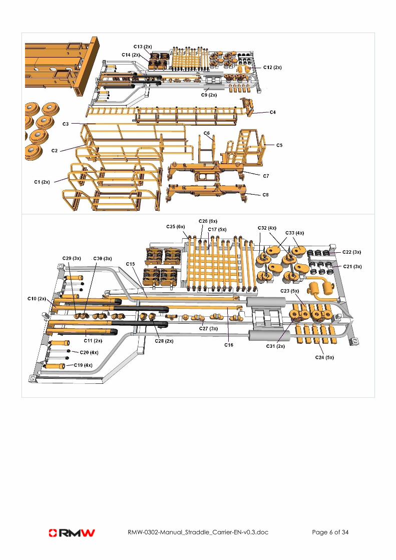
PRODUCT COMPONENTS LIST
This product consists of: 123 parts; Base color is any color (e.g. yellow, red)
No Description Paint advise
A -
A1 Frame Base color
A2 Frame (note the difference as circled) Base color
B -
B1 Cabin White
B2 Cabin roof White
B3 Chair assembly Black
B4 Railing (4x) Base color
B5 Spreader, beam, yoke beam (2x) Base color
B6 Underside Frame (2x) Base color
B7 Pedestal (2x) Base color
B8 Spreader, mid frame Base color
B9 Cylinder movement support tool any
B10 Cylinder shaft (2x) Base color
B11 Wheel rim (8x) Base color
B12 Hubcap (8x) Base color
B13 Wheel (8x) Black
B14 Wheel suspension, powered (2x) Base color
B15 Wheel suspension, powered (2x) Base color
B16 Wheel suspension (2x) Base color
B17 Wheel suspension (2x) Base color
B18 Cylinders (2x) Silver + Base color
C -
C1 Railing (2x) Base color
C2 Railing Base color
C3 Railing Base color
C4 Ladder Base color
C5 Railing + ladder Base color
C6 Railing Base color
C7 Spreader Base color
C8 Spreader Base color
C9 Exhaust pipes (2x) Grey
C10 Cable boom (extended) (2x) Base color + black
C11 Cable beam (2x) Base color + black
C12 Filter (2x) Base color
C13 Cog-wheels (2x) Base color
C14 Cog-wheels (2x) Base color
C15 Cable boom Base color
C16 Cable boom Base color
C17 Drive train pipes (5x, of which 1x spare part) Base color

RMW-0302-Manual_Straddle_Carrier-EN-v0.3.doc Page 4 of 34
C18 Cable end connectors (2x) – integrated in part D Base color
C19 Cylinder shaft (4x, of which 2x spare parts) Base color
C20 Cylinder (4x, of which 2x spare parts) Silver
C21 Gear wheel (3x, of which 1x spare part) Grey
C22 Gear wheel (4x, of which 2x spare part) Grey
C23 Cover plate small (5x, of which 1x spare part) Base color
C24 Cover plate big (5x, of which 1x spare part) Base color
C25 Drive train connectors long (6x, of which 2x spare
parts) Base color
C26 Drive train connectors short (6x, of which 2x spare
parts) Base color
C27 Drive train connector (3x, of which 1x spare part) Base color
C28 Drive train connector (2x) Base color
C29 Drive train connector (3x, of which 1x spare part) Base color
C30 Drive train connector (3x, of which 1x spare part) Base color
C31 Drive train connector (2x) Base color
C32 Drive train connector (4x) Base color
C33 Drive train connector (4x) Base color
D Frame Base color
PRODUCT PHOTO:
Driver not
included;
product
shown in
dioarama

RMW-0302-Manual_Straddle_Carrier-EN-v0.3.doc Page 5 of 34
Note orientation within red circles for parts B14-B17 !
RMW-0302-Manual_Straddle_Carrier-EN-v0.3.doc Page 6 of 34

RMW-0302-Manual_Straddle_Carrier-EN-v0.3.doc Page 7 of 34
Note that part
A2 has an
opening for
the cabin
attachment
GENERIC INSTRUCTIONS
Cleaning:
If you have an ultrasonic cleaner (like from Conrad or Harborfreight), use that one with cold or luke-warm
water to which you have added some dish-washing liquid to clean the parts for 3 minutes.
Alternative, clean the parts by hand in water with dish-washing liquid.
You can use a soft toothbrush.
For ultrasonic cleaners, refer e.g. to:
http://www.conrad.de/ce/de/overview/0601120/Ultraschallreiniger
http://www.harborfreight.com/catalogsearch/result?q=ultrasonic+cleaner
Separating parts:
To separate/cut off all parts from the sprue, you either use a hobby-knife or a small scissors.
If you remove the complete sprue from the parts, you might find it more difficult to hold them for painting; so
leaving a piece of the sprue to each part might be beneficial (only remove the remaining sprue piece after
painting); however, you will not be able to do a test assembly if you leave a piece of the sprue to the part.
Painting:
Ordinary paint as found in car shop accessories can be used. Hobby acrylic paint should also be fine.
First (spray) paint a white base layer. Then multiple layers of your preferred color. After assembly and
finishing (decals), use a clear lacquer layer of paint to seal.
For White Strong and Flexible plastic material, you will have to use quite a few layers of paint, as the material
is porous, so will absorb a lot of paint.
Glue-ing:
Only use ‘super-glue’ (cyancrylat)
Storage:
Dust-free at room temperature, protect from UV radiation
Working order:
First clean the product carefully. Remove remaining oil, grease and wax.
Separate parts from the sprue before or after painting. Followed by the assembly and finishing.
Safety guidelines:
During cleaning, painting and assembly of the product, use gloves to protect your hands and goggles to
protect your eyes. The product might contain oily grease and wax like support material.
If in contact with your skin, clean your skin with abundant water and soap.
Before eating or drinking, always clean your hands thoroughly if you have touched the product.

RMW-0302-Manual_Straddle_Carrier-EN-v0.3.doc Page 8 of 34
ADDITIONAL INFORMATION
-
ASSEMBLY AND PAINTING INSTRUCTIONS
Follow the generic instructions on cleaning and separating parts
1
Clean the parts while still attached to the sprue.
Make sure to especially clean also the inside of the listed parts to remove all inside grease:
- cylinders C19 and B10
- spreader parts B5 and B8
- frame parts A1 and A2 and D
Part B3 (chair assembly): remove all wax between the floor bars
Split parts A1 and A2 (remove the sprue completely).
Spray paint all parts in white primer.
Cut off part groups with a hobby knife or small scissors for separate painting:
- White: cabin parts (B1 & B2)
- Black: all wheels & chair (B3 and B13); optionally paint the inner rim of the wheel in your base
color (see blue arrow in first diagram of step 3)
- Grey: exhausts (C9), bottom attachment of shaft (B14, B15, B16, B17), gear wheels (C21, C22
including parts in C13, C14)
- Silver: cylinder shaft (C20, B18)
Spray paint all remaining parts in your base color of choice.
! Only after painting and thorough drying continue.
Cut of the needed parts when needed, and touch up the sprue connecting side.

RMW-0302-Manual_Straddle_Carrier-EN-v0.3.doc Page 9 of 34
2
Assembly
Follow the order as stipulated below:
1. Wheel assembly
2. Frame
3. Cylinders & gear wheels
4. Spreader
5. Cabin (with glazing)
6. Wheel & Steering assembly
7. Decals I
8. Cable routing
9. Railing (apply grid decals before assembly!)
10. Decals II
3
Wheel assembly
Lay B11 flat on table, with the smaller part up
Press B13 width the widest part down onto it (note blue arrow)
Press B11 slightly more into B13, aligning the inside (see red circle)
Rotate B11+B13 assembly
Repeat 8x
Push B11+B13 assembly onto the axles on B14, B15, B16, B17
Remove the sprue attachment from B12 (see red arrow)
Rotate the cap and push it onto the axle (apply a tiny amount of super glue to the inside first, see blue
arrow)
Make sure the wheel can rotate properly!
Repeat 8x

RMW-0302-Manual_Straddle_Carrier-EN-v0.3.doc Page 10 of 34
4
Frame
Push 4 parts C23 onto A1 & A2 and 4 parts C24 on D

RMW-0302-Manual_Straddle_Carrier-EN-v0.3.doc Page 11 of 34
5
Cylinders & gear wheels
Glue B18 to C14 (2x)
! Install B10 from below into part D (do NOT glue)
Note that the opening in B10 should be pointing downward (see red circle)

RMW-0302-Manual_Straddle_Carrier-EN-v0.3.doc Page 12 of 34
Push C21 into place on part D (from above) –front side
Push C22 into place on part D (from above)-back side (=exhaust side)
Install B18 into B10 and position into part D (do NOT glue)

RMW-0302-Manual_Straddle_Carrier-EN-v0.3.doc Page 13 of 34
Test if C13 fits in D
!
Attach part D to A1 and A2 (you might want to apply some glue at the connectors) – align properly
vertical
Make sure that the railing of A1 and A2 is facing to the inside of the model, and the cabin attachment
opening is at the correct side.
Refer to the blue circles
All parts to be glued in place onto A1 and A2:
Install the exhausts C9 (2x)
Install filters C12 (2x)
Install B6 (2x)

RMW-0302-Manual_Straddle_Carrier-EN-v0.3.doc Page 14 of 34
6
Spreader
Make sure that both parts B5 can slide freely in B8
Make sure that both parts B5 can slide through parts C7 and C8

RMW-0302-Manual_Straddle_Carrier-EN-v0.3.doc Page 15 of 34
Install C7 and C8 on B8 (you might want to apply some glue)
Slide B5 into B8 (do NOT glue)
Note that the hooks are pointing correctly upwards
Make sure this assembly can move vertically between A1 and A2 (some light friction is good) without
glueing (cables will be attached later to hold the spreader in place)
Note that C7 is at the back

RMW-0302-Manual_Straddle_Carrier-EN-v0.3.doc Page 16 of 34
7
Cabin (with glazing)
Cut out the glazing from clear plastic sheet; use the sizes as on the decal sheet as guide
Install parts ‘a’ to the insides of part B1
Install part ‘b’ to the floor of the cabin (from inside) to B1
Install the front and rear windows ‘c’ to the inside: the smallest part goes to B2, the other two to B1
Install the seat B3 into B1 -> make sure the seat is facing the correct direction (see figure, entrance door
is at right hand side of driver) (Insert a driver figure –not included- if required now!)
Glue B2 on top of B1
8
Wheel & Steering assembly
Do NOT use glue unless stated!
Insert the assemblies of B14, B15, B16 and B17 into part A1 and A2 from the bottom.

RMW-0302-Manual_Straddle_Carrier-EN-v0.3.doc Page 17 of 34
Fragile
Push the 4 caps C33 on top of the wheel assemblies (some glue might be required)
Make sure parts C33 are pointing slightly inwards (towards the center of the model), and all wheel
assemblies can freely rotate
Fragile Push the 4 caps C32 on top of the wheel assemblies (some glue might be required)
Take note of the positioning of the parts C32
RMW-0302-Manual_Straddle_Carrier-EN-v0.3.doc Page 18 of 34
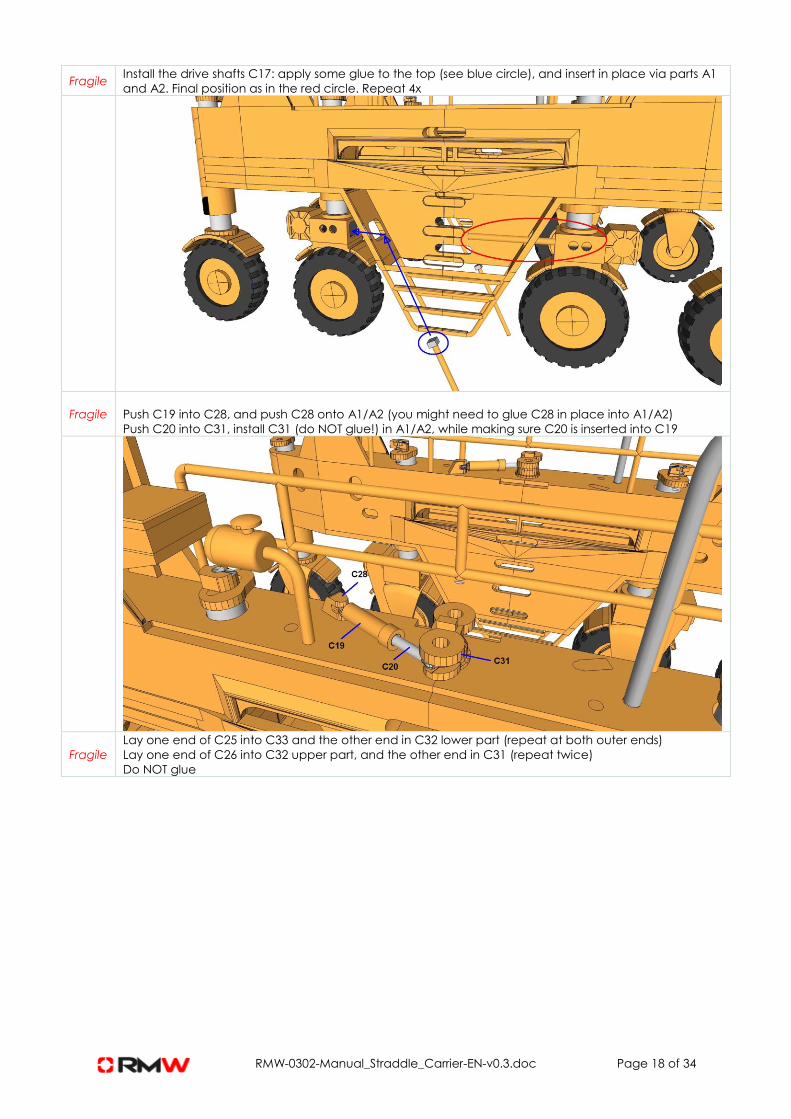
Fragile Install the drive shafts C17: apply some glue to the top (see blue circle), and insert in place via parts A1
and A2. Final position as in the red circle. Repeat 4x
Fragile
Push C19 into C28, and push C28 onto A1/A2 (you might need to glue C28 in place into A1/A2)
Push C20 into C31, install C31 (do NOT glue!) in A1/A2, while making sure C20 is inserted into C19
Fragile
Lay one end of C25 into C33 and the other end in C32 lower part (repeat at both outer ends)
Lay one end of C26 into C32 upper part, and the other end in C31 (repeat twice)
Do NOT glue

RMW-0302-Manual_Straddle_Carrier-EN-v0.3.doc Page 19 of 34
Fragile
Install (use glue) C27 on top of C31
Install (use glue) C29 and C30 on top of C32 -> note which number is at which side on A1/A2!
Make sure the shafts C25/C26 can freely move, but not fall out

RMW-0302-Manual_Straddle_Carrier-EN-v0.3.doc Page 20 of 34
Fragile The result should be that you can slightly turn the wheels, do this careful!

RMW-0302-Manual_Straddle_Carrier-EN-v0.3.doc Page 21 of 34
9
Cable routing
For each side/cylinder, both 2xA (outer) and 2xB (inner) side need to be routed. I.e. in total 8 cables.
Push B18+C14 piston assembly as much as possible into cylinder B10
Place C7+B8+C8 (the spreader) on ‘ground level’, in between the wheels.
Position C13 in in the middle of C14 and C22 while applying the cabling (as easier).
Cut 8 cables of thin (black) yarn, each 40 to 45 cm in length.
Glue one cable end to start (part C8) for cabling schema A, repeat 4x
Glue one cable end to start (part C7) for cabling schema B, repeat 4x
After the all cabling is applied, but before the cable ends are glued in place to part C18, position all
parts in the right starting positions:
1) move C13 near C22 (see pictures later) and glue in place
2) move C7+B8+C8 (the spreader) up as much as possible, while maintaining piston assembly
B18+C14 in positon; do this by pulling the cabling at the same time at the loose end (not yet
glued to C18)
‘Test run’ the cabling, still not glued in place to part C18, but just fixate it temporarily, and try if you can
lower the spreader sufficiently down - vertical displacement-, to place a container on the ground level.
Do this by moving the piston assembly B18+C14 towards part C22.
If you are satisfied with the result, cut the cables to length, and glue the cable ends to part C18 (8x).
Part C18 connects both cable ends of routing ‘A’ (outer connectors) and routing ‘B’ (inner
connectors).
If you are not satisfied, tweak the cabling by pulling the loose cable ends and pushing the spreader up
until the minimum height you want to maintain (e.g. pick up a container from a truck), then fixate the
cable ends temporarily, and by moving the piston assembly inwards in the cylinder B10, double check if
the height you can reach is sufficient enough for your purposes. If satisfied, glue the cable ends in
place to C18.
The original cabling schema is as below.
Note that this schema might cause a lot of friction (depending on the yarn thickness used), and certain
areas (shown in red) of schema A are quite difficult.
end end
start
start
A B
C7C8
C13 C13
C14 C14
C18 C18
C21 C22
A A
B B
A A
B B
Original cabling routing schemas: Side views
Original cabling routing schemas: Top view
Section in red is difficult

RMW-0302-Manual_Straddle_Carrier-EN-v0.3.doc Page 22 of 34
An alternative cabling schema is shown also below.
This will cause less friction, as less cable is used/1 loop less, but as a result the available cable length in
the system is more limited, thus reducing the vertical displacement of the spreader. You will however
be able to pick up a container from a truck, and place on top of another container.
If you choose for this alternative, follow all steps as mentioned above and below, except the loop
which is not included in this alternative. Don’t forget to do a test run of the cabling before fixing in
place!
Alternative cabling routing schemas: Side views
end end
start
start
A B
C7C8
C13 C13
C14 C14
C18 C18
C21 C22
Same as aboveLess 1 looping
(section in red above)

RMW-0302-Manual_Straddle_Carrier-EN-v0.3.doc Page 23 of 34
12a
12b
Note that C13 is pulled up from its’ final position during cabling!

RMW-0302-Manual_Straddle_Carrier-EN-v0.3.doc Page 24 of 34
12c
12d
B routing:

RMW-0302-Manual_Straddle_Carrier-EN-v0.3.doc Page 25 of 34
12e1
12e2
12e3
RMW-0302-Manual_Straddle_Carrier-EN-v0.3.doc Page 26 of 34
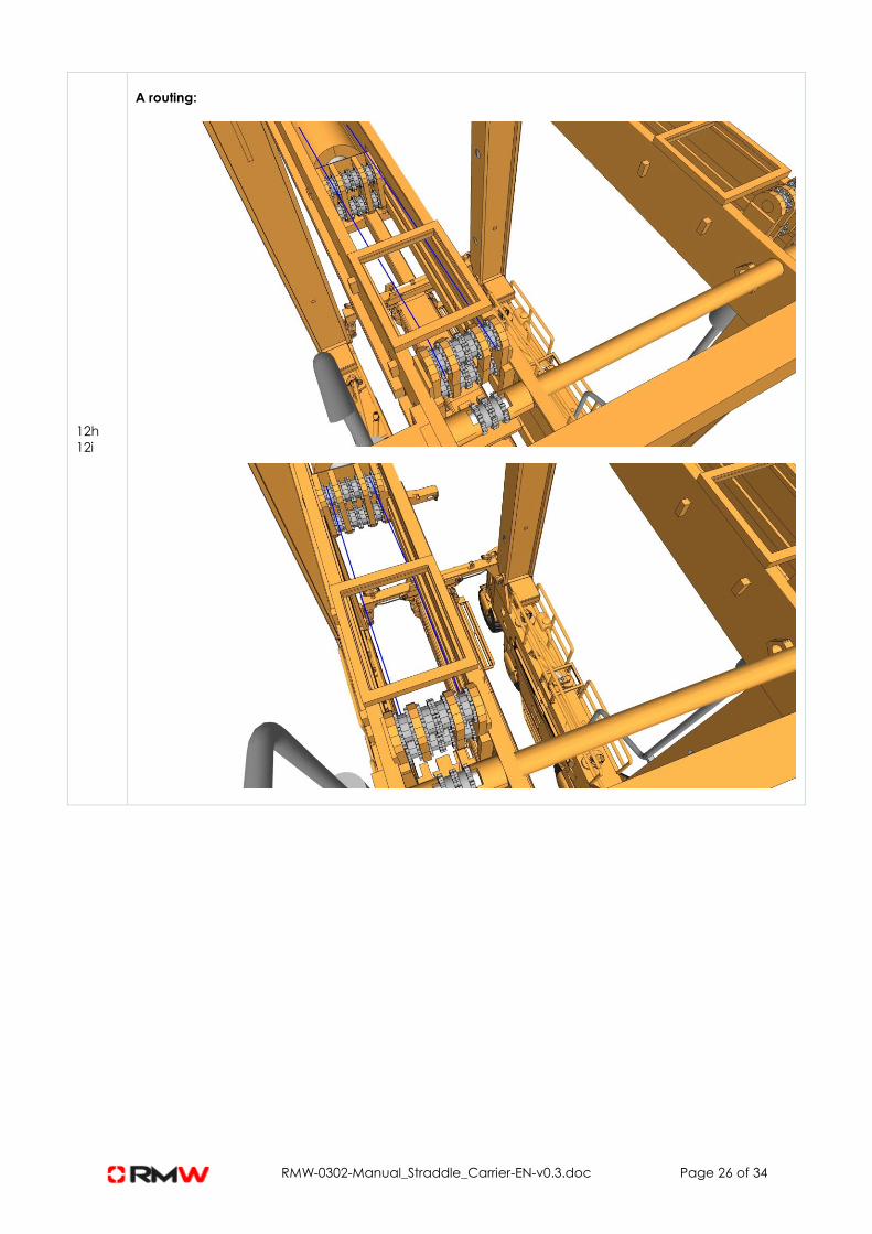
12h
12i
A routing:

RMW-0302-Manual_Straddle_Carrier-EN-v0.3.doc Page 27 of 34
12j
12-i4
12-i5
When done, move C13 down in place. (glue optionally)
(in diagrams below not all cables are shown!)

RMW-0302-Manual_Straddle_Carrier-EN-v0.3.doc Page 28 of 34
12-k
12-l
12-m

RMW-0302-Manual_Straddle_Carrier-EN-v0.3.doc Page 29 of 34
To move the cylinders back and forth, and thus the spreader up and down, use tool B9
(slide in from below)
10
Decals I
Print out all grill decals and cut.
Cut from clear plastic sheets the same size as the decals.
Try fit these plastic sheets in place first, cut to fit if required, before applying the decals on these sheets.
Install plastic sheet + decal 4 onto part C3
Install plastic sheet + decal 5 onto part C2
Install plastic sheet + decal 6 onto part C1 middle section (2x)
Install plastic sheet + decal 7 onto part C6
Install plastic sheet + decal 8 onto part D (4x)
Install plastic sheet + decal 9 onto part B7 (2x)
Install plastic sheet + decal 10 onto part C4
Install plastic sheet + decal 11 onto part C5
Install plastic sheet + decal 12 onto C1 (optional, as very small)
11
Railing
All glue in place:
Install part C1 onto A1/A2 (2x)
Install part C2 onto A1
Install part C3 onto A2
Install part C5 (with the small ladder) onto A2
Install part C6 onto A2

RMW-0302-Manual_Straddle_Carrier-EN-v0.3.doc Page 30 of 34
Install B7 onto A1/A2 (2x)
Install (glue) part C4 (ladder) onto A1
Install (glue) B4 (railing) onto A1 and A2 (4x)
12
Finalisation
Install (glue) cabin on C5
The cable booms C10 and C11 are not to be glued, but used interchangeable, based on if 20” or 40”
containers are hoisted.
The cable guider C15 and C16 should not be glued, and only installed after the cabling to
spreaderbeam B8 is in place. C15 fits into C7.

RMW-0302-Manual_Straddle_Carrier-EN-v0.3.doc Page 31 of 34
13
Decals II
You may wish to apply some warning lining to the wheel shafts, front and back. (decals 1, 2 or 3)

RMW-0302-Manual_Straddle_Carrier-EN-v0.3.doc Page 32 of 34
Apply final touch paint –up. Result:
14 Spray paint all parts with clean lacquer (protective layer).
Note
Containers of Herpa brand will fit; use some ‘bluetag’ temporary sticking paste to fix them
ADDITIONAL INFORMATION
PRODUCT PAINTING EXAMPLES

RMW-0302-Manual_Straddle_Carrier-EN-v0.3.doc Page 33 of 34
Example
with
colors
Applied
in
diorama
setting
Refer to our website for more product photos
For any questions/suggestions or additional information, contact us at
Customer Service Department, email us: [email protected]
Website: robs-mw.com Facebook: facebook.com/robsmw
Subscribe to our newsletter and/or product updates!
DISCLAIMER

RMW-0302-Manual_Straddle_Carrier-EN-v0.3.doc Page 34 of 34
Not included is paint, glue, tools.
Decals –if applicable for this product - should be self-printed on suitable material.
This product is only suitable for the experienced scale modeler (adults, 14 years up). Small parts included!
Warning:
Please note that the 3D printing materials we use for manufacturing the products make the products suitable
only for decorative purposes and they are not suited for any other purpose. The products are not suited to
be used as toys, to be given to children. The products should not come in contact with electricity or food &
drinks and should be kept away from heat.
Due to the new technologies used to fabricate these products, different procedures might need to be used
to achieve similar results as for products produced with conventional technologies.
Photographs and drawings can show pre-production samples.
Subject to alterations in assortment, printing, shape and colors.
Technical details information about the example provided ‘as-is’