Product description EM powerLED PRO DIM - …€¦ · 9 DALI functionality ... EM powerLED PRO DIM...
78
ø4,5 41 82 175 34 183 34 209 ø4,5 33 82 175,5 175 34 183 2 34 209 175 34 183 ø4,5 41 82 34 209 175,5 175 34 183 ø4,5 33 82 34 209 LED Driver Product description EM powerLED PRO DIM
Transcript of Product description EM powerLED PRO DIM - …€¦ · 9 DALI functionality ... EM powerLED PRO DIM...

ø4,5
41 82
175
34
183
34
209
ø4,5
3382
175,5
175
34
183
82
34
209
175
34
183
ø4,5
41 82
34
209
175,5
175
34
183
ø4,5
3382
34
209
LED Driver
Product descriptionEM powerLED PRO DIM

Product manual EM powerLED PRO DIM | 01-2018 | 1.1 | en
Table of Contents
c 2 / 78
Table of contentsValidity . . . . . . . . . . . . . . . . . . . . . . . . . . . . . . . . . . . . . . . . . . . . . . . . . . . . . . . . . . . . . . . . . . . . . . . . . . . 4Safety instructions . . . . . . . . . . . . . . . . . . . . . . . . . . . . . . . . . . . . . . . . . . . . . . . . . . . . . . . . . . . . . . . . . 5
Intended use . . . . . . . . . . . . . . . . . . . . . . . . . . . . . . . . . . . . . . . . . . . . . . . . . . . . . . . . . . . . . . . . . . . . . . . . . . . . . 5
Dangers associated with the operation of the system . . . . . . . . . . . . . . . . . . . . . . . . . . . . . . . . . . . . . . . . . . . . . . 5
Environment . . . . . . . . . . . . . . . . . . . . . . . . . . . . . . . . . . . . . . . . . . . . . . . . . . . . . . . . . . . . . . . . . . . . . . . . . . . . . . 5
Additional instructions . . . . . . . . . . . . . . . . . . . . . . . . . . . . . . . . . . . . . . . . . . . . . . . . . . . . . . . . . . . . . . . . . . . . . . 6
Introduction . . . . . . . . . . . . . . . . . . . . . . . . . . . . . . . . . . . . . . . . . . . . . . . . . . . . . . . . . . . . . . . . . . . . . . . 7
About the device . . . . . . . . . . . . . . . . . . . . . . . . . . . . . . . . . . . . . . . . . . . . . . . . . . . . . . . . . . . . . . . . . . . . . . . . . . 7
Testing of emergency systems . . . . . . . . . . . . . . . . . . . . . . . . . . . . . . . . . . . . . . . . . . . . . . . . . . . . . . . . . . . . . . . 7
Portfolio of products . . . . . . . . . . . . . . . . . . . . . . . . . . . . . . . . . . . . . . . . . . . . . . . . . . . . . . . . . . . . . . . . 8
Housing variants . . . . . . . . . . . . . . . . . . . . . . . . . . . . . . . . . . . . . . . . . . . . . . . . . . . . . . . . . . . . . . . . . . . . . . . . . . 8
Output voltage range . . . . . . . . . . . . . . . . . . . . . . . . . . . . . . . . . . . . . . . . . . . . . . . . . . . . . . . . . . . . . . . . . . . . . . . 9
DALI functionality . . . . . . . . . . . . . . . . . . . . . . . . . . . . . . . . . . . . . . . . . . . . . . . . . . . . . . . . . . . . . . . . . 10
DALI standard . . . . . . . . . . . . . . . . . . . . . . . . . . . . . . . . . . . . . . . . . . . . . . . . . . . . . . . . . . . . . . . . . . . . . . . . . . . 10
DALI in Action . . . . . . . . . . . . . . . . . . . . . . . . . . . . . . . . . . . . . . . . . . . . . . . . . . . . . . . . . . . . . . . . . . . . . . . . . . . 10
Commissioning . . . . . . . . . . . . . . . . . . . . . . . . . . . . . . . . . . . . . . . . . . . . . . . . . . . . . . . . . . . . . . . . . . . . . . . . . . 11
Functions in mains operation . . . . . . . . . . . . . . . . . . . . . . . . . . . . . . . . . . . . . . . . . . . . . . . . . . . . . . . . 12
DSI . . . . . . . . . . . . . . . . . . . . . . . . . . . . . . . . . . . . . . . . . . . . . . . . . . . . . . . . . . . . . . . . . . . . . . . . . . . . . . . . . . . . 14
switchDIM . . . . . . . . . . . . . . . . . . . . . . . . . . . . . . . . . . . . . . . . . . . . . . . . . . . . . . . . . . . . . . . . . . . . . . . . . . . . . . . 15
corridorFUNCTION V2 . . . . . . . . . . . . . . . . . . . . . . . . . . . . . . . . . . . . . . . . . . . . . . . . . . . . . . . . . . . . . . . . . . . . . 19
Dimming technology . . . . . . . . . . . . . . . . . . . . . . . . . . . . . . . . . . . . . . . . . . . . . . . . . . . . . . . . . . . . . . . . . . . . . . 24
Adjustable output current . . . . . . . . . . . . . . . . . . . . . . . . . . . . . . . . . . . . . . . . . . . . . . . . . . . . . . . . . . . . . . . . . . . 25
Constant Light Output and Over the Lifetime . . . . . . . . . . . . . . . . . . . . . . . . . . . . . . . . . . . . . . . . . . . . . . . . . . . . 26
Intelligent Temperature Guard . . . . . . . . . . . . . . . . . . . . . . . . . . . . . . . . . . . . . . . . . . . . . . . . . . . . . . . . . . . . . . . 29
Power-up fading . . . . . . . . . . . . . . . . . . . . . . . . . . . . . . . . . . . . . . . . . . . . . . . . . . . . . . . . . . . . . . . . . . . . . . . . . . 31
ready2mains . . . . . . . . . . . . . . . . . . . . . . . . . . . . . . . . . . . . . . . . . . . . . . . . . . . . . . . . . . . . . . . . . . . . . . . . . . . . 32
Adjustable output current . . . . . . . . . . . . . . . . . . . . . . . . . . . . . . . . . . . . . . . . . . . . . . . . . . . . . . . . . . . . . . . . . . . 33
Addressing function EZ easy addressing . . . . . . . . . . . . . . . . . . . . . . . . . . . . . . . . . . . . . . . . . . . . . . . . . . . . . . . 35
Settings for emergency tests . . . . . . . . . . . . . . . . . . . . . . . . . . . . . . . . . . . . . . . . . . . . . . . . . . . . . . . . 37
Time intervals between emergency tests . . . . . . . . . . . . . . . . . . . . . . . . . . . . . . . . . . . . . . . . . . . . . . . . . . . . . . . 37
Type of test system: DALI-controlled or selftest mode . . . . . . . . . . . . . . . . . . . . . . . . . . . . . . . . . . . . . . . . . . . . 38
Adaptive test mode . . . . . . . . . . . . . . . . . . . . . . . . . . . . . . . . . . . . . . . . . . . . . . . . . . . . . . . . . . . . . . . . . . . . . . . 39
Functionality of the test switch . . . . . . . . . . . . . . . . . . . . . . . . . . . . . . . . . . . . . . . . . . . . . . . . . . . . . . . . . . . . . . . 39
Intelligent multilevel charging system . . . . . . . . . . . . . . . . . . . . . . . . . . . . . . . . . . . . . . . . . . . . . . . . . . . . . . . . . 40

Product manual EM powerLED PRO DIM | 01-2018 | 1.1 | en
Table of Contents
c 3 / 78
...
Intelligent multilevel charging system . . . . . . . . . . . . . . . . . . . . . . . . . . . . . . . . . . . . . . . . . . . . . . . . . . . . . . . . . 40
Rest mode, Inhibit mode and Relight command . . . . . . . . . . . . . . . . . . . . . . . . . . . . . . . . . . . . . . . . . . . . . . . . . 42
Prolong time . . . . . . . . . . . . . . . . . . . . . . . . . . . . . . . . . . . . . . . . . . . . . . . . . . . . . . . . . . . . . . . . . . . . . . . . . . . . . 45
Indicator LED . . . . . . . . . . . . . . . . . . . . . . . . . . . . . . . . . . . . . . . . . . . . . . . . . . . . . . . . . . . . . . . . . . . . . . . . . . . . 46
Functions in emergency operation . . . . . . . . . . . . . . . . . . . . . . . . . . . . . . . . . . . . . . . . . . . . . . . . . . . 48A typical installation . . . . . . . . . . . . . . . . . . . . . . . . . . . . . . . . . . . . . . . . . . . . . . . . . . . . . . . . . . . . . . . 49
Initial startup . . . . . . . . . . . . . . . . . . . . . . . . . . . . . . . . . . . . . . . . . . . . . . . . . . . . . . . . . . . . . . . . . . . . . . . . . . . . . 49
Installation without a control system . . . . . . . . . . . . . . . . . . . . . . . . . . . . . . . . . . . . . . . . . . . . . . . . . . . . . . . . . . 49
Determining light output in emergency operation . . . . . . . . . . . . . . . . . . . . . . . . . . . . . . . . . . . . . . . 51
Parameter 1: LED forward voltage . . . . . . . . . . . . . . . . . . . . . . . . . . . . . . . . . . . . . . . . . . . . . . . . . . . . . . . . . . . . 51
Parameter 2: LED current . . . . . . . . . . . . . . . . . . . . . . . . . . . . . . . . . . . . . . . . . . . . . . . . . . . . . . . . . . . . . . . . . . 54
Parameter 3: Light output in emergency operation . . . . . . . . . . . . . . . . . . . . . . . . . . . . . . . . . . . . . . . . . . . . . . . 56
Compatibility between LED module and LED Driver . . . . . . . . . . . . . . . . . . . . . . . . . . . . . . . . . . . . . 57
Comparison of data sheet values with a 5-point guideline . . . . . . . . . . . . . . . . . . . . . . . . . . . . . . . . . . . . . . . . . 57
Application of the 5-point guideline . . . . . . . . . . . . . . . . . . . . . . . . . . . . . . . . . . . . . . . . . . . . . . . . . . . . . . . . . . . 60
Practical tests . . . . . . . . . . . . . . . . . . . . . . . . . . . . . . . . . . . . . . . . . . . . . . . . . . . . . . . . . . . . . . . . . . . . . . . . . . . . 66
Installation notes . . . . . . . . . . . . . . . . . . . . . . . . . . . . . . . . . . . . . . . . . . . . . . . . . . . . . . . . . . . . . . . . . . 67
Safety information . . . . . . . . . . . . . . . . . . . . . . . . . . . . . . . . . . . . . . . . . . . . . . . . . . . . . . . . . . . . . . . . . . . . . . . . 67
Function of the earth terminal . . . . . . . . . . . . . . . . . . . . . . . . . . . . . . . . . . . . . . . . . . . . . . . . . . . . . . . . . . . . . . . 68
Routing the wires . . . . . . . . . . . . . . . . . . . . . . . . . . . . . . . . . . . . . . . . . . . . . . . . . . . . . . . . . . . . . . . . . . . . . . . . . 70
Maximum loading of circuit breakers . . . . . . . . . . . . . . . . . . . . . . . . . . . . . . . . . . . . . . . . . . . . . . . . . . . . . . . . . . 72
Reference list . . . . . . . . . . . . . . . . . . . . . . . . . . . . . . . . . . . . . . . . . . . . . . . . . . . . . . . . . . . . . . . . . . . . . 77
Related documents . . . . . . . . . . . . . . . . . . . . . . . . . . . . . . . . . . . . . . . . . . . . . . . . . . . . . . . . . . . . . . . . . . . . . . . 77
Downloads . . . . . . . . . . . . . . . . . . . . . . . . . . . . . . . . . . . . . . . . . . . . . . . . . . . . . . . . . . . . . . . . . . . . . . . . . . . . . . 77
Additional information . . . . . . . . . . . . . . . . . . . . . . . . . . . . . . . . . . . . . . . . . . . . . . . . . . . . . . . . . . . . . . . . . . . . . 78

Product manual EM powerLED PRO DIM | 01-2018 | 1.1 | en
Scope of documentation
c 4 / 78
1. ValidityThis operating instruction is valid for combined LED Drivers for general and emergency lighting from the EMpowerLED PRO DIM 45W series.
The series comprises additional versions. However, the other versions EM powerLED ST FX 45W, EM powerLEDBASIC FX 80W and EM powerLED BASIC FX 50W are not covered within this documentation.
TRIDONIC GmbH & Co KG is constantly striving to improve all its products. This means that there may be changesin shape, features and technology.Claims cannot therefore be made on the basis of information, diagrams or descriptions in these instructions.The latest version of these operating instructions is available on our home page athttp://www.tridonic.com/com/en/operating-instructions.asp
Copyright
This documentation may not be changed, expanded, copied or passed to third parties without the prior writtenagreement of TRIDONIC GmbH & Co KG.We are always open to comments, corrections and requests.
Please send them to [email protected]
Imprint
Tridonic GmbH & Co KGFärbergasse 156851 DornbirnAustria
T +43 5572 395-0F +43 5572 20176
www.tridonic.com
...

Product manual EM powerLED PRO DIM | 01-2018 | 1.1 | en
Safety instructions
c 5 / 78
2. Safety instructionsThe instructions in this section have been compiled to ensure that operators and users of combined emergency
of the EM powerLED PRO DIM 45W series from Tridonic are able to detect potential risks inlighting LED Driversgood time and take the necessary preventative measures.The operator must ensure that all users fully understand these instructions and adhere to them. This device mayonly be installed and configured by suitably qualified personnel.
2.1. Intended use
2.1.1. Proper useOperation of LED modules in general lighting and in single battery supplied emergency lighting. The device mayonly be used for this intended purpose.
2.1.2. Improper useOutdoor use. Extensions and modifications to the product.
2.2. Dangers associated with the operation of the system
2.3. Environment
½ WARNING!
Improper use could result in injury, malfunction or damage to property.It must be ensured that the operator informs every user of existing hazards.
½ DANGER!
Danger of electrocutionDisconnect the power to the entire lighting system before working on the lighting system!
½ DANGER!
Not to be used in corrosive or explosive environments.

Product manual EM powerLED PRO DIM | 01-2018 | 1.1 | en
Safety instructions
c 6 / 78
2.4. Additional instructions
...
½ CAUTION!
Risk of damage caused by humidity and condensation
Only use the LED Driver in dry rooms and protect it against humidity!_
Prior to commissioning the system, wait until the LED Driver is at room temperature and completely dry!_
½ CAUTION!
Electromagnetic compatibility (EMC)Although the device meets the stringent requirements of the appropriate directives and standards onelectromagnetic compatibility, it could potentially interfere with other devices under certain circumstances!

Product manual EM powerLED PRO DIM | 01-2018 | 1.1 | en
Introduction
c 7 / 78
3. Introduction3.1. About the device
The combined LED Drivers for general and emergency lighting EM powerLED is the smart solution where costoptimised or feature driven emergency lighting is required. It integrates functions for mains operation andemergency lighting into one unit. Devices are available for a broad range of applications from compact housings forinstallations inside the luminaire to independent devices with strain relief for use with downlights. The strain reliefvariant (SR) in conjunction with plug-in remote batteries offers a turnkey solution.
Available are versions for manual testing (BASIC), versions for selftest (ST) and DALI addressable devices (PRO)for automatically controlled and monitored testing.
This document covers the PRO version of the portfolio. The selftest (ST) version is covered in a separatedocumentation (see ).Reference list, p. 77
The innovative compact PRO versions are true all in one products which enable lighting control, dimming capabilityand emergency testing with a single DALI address. The devices are fully compatible with the LED Driver seriesPREMIUM (PRE) from Tridonic and can be used seamlessly in any installation with these devices.
3.2. Testing of emergency systemsThere are statutory requirements covering the testing of emergency systems in buildings accessible to the public.This includes that testing must be carried out at a time of minimum risk, normally during unsocial hours, and mustallow time for the batteries to be recharged before the next expected occupancy of the building.
Without automated test systems all steps must be performed manually. This includes the initiation of the test byinterrupting the power supply, the visual inspection of each luminaire and the logging of all test results.
The combined emergency LED Driver EM powerLED enables automated tests with a number of advantages:
...
In conjunction with the appropriate DALI control system the EM powerLED PRO DIM covers the completetest procedure including error indication, monitoring and logging. This is possible without any expensive,time-consuming testing procedures. Tests are therefore more reliable and cheaper.
_
Combining mains and emergency operation in one unit eliminates compatibility issues between LED Driverand emergency units and ensures an optimal electromagnetic compatibility.
_
The EM powerLED PRO DIM devices are designed to meet the requirements of IEC 62034 and the DALIstandard IEC 62386-101 Vers. 2, IEC 62386-102 and IEC 62386-202 Vers. 2.
_

Product manual EM powerLED PRO DIM | 01-2018 | 1.1 | en
Portfolio of products
c 8 / 78
4. Portfolio of products4.1. Housing variantsThe EM powerLED PRO DIM is available in two different housing variants: compact and compact strain relief(independent).
Image Description
Housing variant compact
Housing variant compact strain relief (independent)
...
Compact shape_
For installations inside the luminaire_
Typical area of application: Spotlights, downlights_
Dimensions: 183 x 82 x 34 mm_
Compact shape_
For installations outside the luminaire_
Typical area of application: Spotlights, downlights_
Dimensions: 209 x 82 x 34 mm_

Product manual EM powerLED PRO DIM | 01-2018 | 1.1 | en
Output voltage range
c 9 / 78
4.2. Output voltage rangeThe output voltage range results from the current selected. The diagrams below show the forward voltage ranges as a function of the output current and are intended as aguide. For detailed values and explanations please refer to the data sheets (see ).Reference list, p. 77
Output voltage [V]
Output current [mA]
Legend:
Operating window 100 %
Operating window dimmed
...

Product manual EM powerLED PRO DIM | 01-2018 | 1.1 | en
DALI functionality
c 10 / 78
5. DALI functionality5.1. DALI standard
DALI (Digital Addressable Lighting Interface) is an interface protocol for digital communication between electroniclighting equipment.
The DALI standard was developed by Tridonic together with renowned manufacturers of operating and controlequipment. Today, these manufacturers belong to the DALI Activity Group which promotes the use and furtherdevelopment of DALI.
The DALI standard is defined in IEC 62386. A test procedure standardised by the DALI Activity Group ensurescompatibility between products from different manufacturers. Tridonic products have undergone this test and meetall the requirements. This is indicated by the logo of the Activity Group DALI on the device.
The agreement by the lighting industry to adopt a common protocol has opened up a virtually unlimited number ofoptions. With the right choice of individual DALI components an extremely wide range of requirements can be met,from operating a simple light switch to lighting management systems for entire office complexes with thousands oflight sources and the integration of centrally controlled and monitored emergency lighting.
5.2. DALI in ActionDALI offers a lot of possibilities:
I NOTICE
devices support the new DALI standard V2 EM powerLED PRO DIM EN 62386-101, EN 62386-102, EN62386-202.
Addressability: All control gear are individually addressable_
DALI line: 64 control gear can be grouped to a line_
DALI groups: Every control gear can be attributed to 16 groups_
Grouping: Possible without complicated rewiring_
Programmability: Individual programmability makes it possible to use functions which transcend the DALIstandard
_
Monitoring by status feedback on the DALI bus_
Wiring: Simple wiring with five pole standard cables and a cable length of max. 300 meters_
Wiring: Polarity-free control lines for mains and control lines_
Wiring: Multiple wiring possibilities (star, series and mixed wiring)_
Unaffected by interruptions: All luminaires receive the same, unaffected digital signal and dimming level_

Product manual EM powerLED PRO DIM | 01-2018 | 1.1 | en
DALI functionality
c 11 / 78
Technical data of a DALI line:
5.3. Commissioning
Further information can be found in the DALI Handbook (see ).Reference list, p. 77
eD ("enhanced DALI") offers extended DALI commands. They can be used to activate specific commands of thecontrol gear. These commands are Tridonic specific. They are not part of the DALI standard and are not publiclyavailable.
...
Unaffected by interruptions: All luminaires receive the same, unaffected digital signal and dimming level_
Similar light level from first to last luminaire_
DALI voltage: 9.5 V - 22.5 VDC_
DALI current supply: max. 250 mA_
Data transfer rate: 1200 Baud_
Maximum line length: up to 300 m (for 1,5 mm )2_
I NOTICE
If the corridorFUNCTION is activated the LED Driver is controlled only by motion detection. To operate the LEDDriver via DALI, DSI or switchDIM the corridorFUNCTION must be deactivated.

Product manual EM powerLED PRO DIM | 01-2018 | 1.1 | en
Functions in mains operation
c 12 / 78
6. Functions in mains operationOverview of the main functions in mains operation:
Area Function
DALI functionality, p. 10
DALI standard Version 2 (V2)
Device type Multi device type: DT1 + DT6
DALI address Single DALI address for mains andemergency operation
Dimming and lightcontrol
Dimming technology, p. 24 Via current amplitude
Dimming range 100 - 1 %
DALI V2-DT6
DSI, p. 14
switchDIM, p. 15
corridorFUNCTION V2, p. 19
Adjustable outputcurrent, p. 25
Adjustable via resistor or I-select 2 plug Step size: 25 mA
Adjustable via DALI V2-DT6 Step size: 1 mA
ready2mains, p. 32 Step size: 1 mA
Functions andperformance
Constant Light Output and Over theLifetime, p. 26
Intelligent Temperature Guard (ITG), p. 29
Standby losses < 0.2 W
Rated supply voltage 220 - 240 V

Product manual EM powerLED PRO DIM | 01-2018 | 1.1 | en
Functions in mains operation
c 13 / 78
Power-up fading, p. 31
...

Product manual EM powerLED PRO DIM | 01-2018 | 1.1 | en
DSI
c 14 / 78
6.1. DSI
6.1.1. DescriptionWith DSI (Digital Serial Interface) it is possible to control DSI capable LED Driver. The DSI control line can be wiredseparately via a two-core cable or together with the mains cable in a five-core cable. Communication is not impairedby the mains cable. In contrast to DALI, there is no individual addressing of the LED Driver with DSI.
DSI offers a series of benefits:
The main benefit of DSI lies in the energy optimised implementation of extensive groups of luminaires (e.g. in sportsstadiums and factories).
6.1.2. Commissioning
Further information can be found in the DALI Handbook (see ).Reference list, p. 77
...
Expansion options via submodules, for example in combination with daylight control or additional switchmodules
_
Wiring: Simple wiring with five pole standard cables and line length of up to 250 metres_
Wiring: Polarity-free control lines can be used for mains and control lines_
Wiring: Multiple wiring possibilities (star, series and mixed wiring)_
Unaffected by electrical interference: All luminaires receive precisely the same interference-sensitive digitalsignal and therefore the same dim level
_
Uniform light level: No voltage drop as in analog applications -› uniform light level from the first to the last lightsource
_
I NOTICE
If the corridorFUNCTION is activated the LED Driver is controlled only by motion. To operate the LED Driver viaDALI, DSI or switchDIM the corridorFUNCTION must be deactivated.

Product manual EM powerLED PRO DIM | 01-2018 | 1.1 | en
switchDIM
c 15 / 78
6.2. switchDIM
6.2.1. DescriptionWith the switchDIM function it is possible to use the mains voltage as a control signal.The phase is connected via a simple standard mains voltage push button to the terminal marked DA/L and theneutral conductor is connected to the terminal DA/N.
Using the function is easy and convenient:
switchDIM is therefore a very simple form of lighting management. It also has a positive effect on material andlabour costs.
The device has a switchDIM memory function. This is used, among other things, for storing the last dimming valuein the event of interruptions in the power supply.When power returns, the device automatically returns to its previous operating state and the light source is dimmedto the stored value.
6.2.2. Commissioning
A short press (50-600 ms) switches the device on or off_
A long press (> 600 ms) fades the connected operating device alternately up and down (between 1 and100 %).
_
½ CAUTION!
Glow switches are not approved for using switchDIM.Glow switches may cause the LED Driver to spontaneously switch on or off or make sudden changes in thedimming value.
½ CAUTION!
To ensure correct operation a sinusoidal mains voltage with a frequency of 50 Hz or 60 Hz is required at theterminal.Special attention must be paid to achieving clear zero crossings. Serious mains faults may impair the operation ofswitchDIM and corridorFUNCTION.
½ CAUTION!
A maximum number of 25 operating devices per switchDIM system should not be exceeded.If you have more devices please use DALI or DSI.
I NOTICE
If the corridorFUNCTION is activated the LED Driver is controlled only by motion. To operate the LED Driver viaDALI, DSI (only PRO DIM) or switchDIM the corridorFUNCTION must be deactivated.

Product manual EM powerLED PRO DIM | 01-2018 | 1.1 | en
switchDIM
c 16 / 78
Using the switchDIM functionswitchDIM is operated by the push button that connects phase with the terminal marked DA/L.
Procedure:
Synchronising devicesIf the devices in a system do not operate synchronously the devices must be synchronised, i.e. put in the samestatus (on/off) and the same dim level.
Procedure:
Changing the fading timeThe default value for the fading time is approx. 3 seconds. It can be changed to approx. 6 seconds.
Procedure:
Switching the LED Driver to automatic mode In automatic mode the device detects which control signal (DALI, DSI, switchDIM, ready2mains) is connected and
automatically switches to the corresponding operating mode.
Procedure:
6.2.3. Installation
Wiring variantsThere are two options for installing switchDIM: four-pole and five-pole wiring
Switch the device on/off by briefly actuating the switch (50-600 ms) or_
Dim the device by holding down the switch (> 600 ms)_
Hold down the switch for 10 seconds→ All devices will be synchronised to the same status→ LEDs will will be set to a uniform light value (approx. 50 %) → The fading time will be set to it default value (approx. 3 seconds)
_
Hold down the switch for 20 seconds→ After 10 seconds: all devices will be synchronised to the same status→ After 20 seconds: a fading time of approx. 6 seconds will be set→ LEDs will be set to a uniform light value (approx. 100 %)
_
Press the switch 5 times within 3 seconds_

Product manual EM powerLED PRO DIM | 01-2018 | 1.1 | en
switchDIM
c 17 / 78
Four-pole wiring
Configuration:
phase (L), neutral (N), control line (S/L), earth
Benefits:
No need for a control line thanks to connecting terminal 8 with the N-connection of the luminaire
Five-pole wiring
Configuration:
phase (L), neutral (N), control line (S/L), earth

Product manual EM powerLED PRO DIM | 01-2018 | 1.1 | en
switchDIM
c 18 / 78
Benefits:
Control can be changed at any time to a digital control signal (DSI or DALI) without having to change the luminaireor provide an additional control line
...
½ CAUTION!
For five-pole wiring the neutral conductor must be connected to DA/N.This prevents 400 V being applied between adjacent terminals if a different phase is used for the control input.

Product manual EM powerLED PRO DIM | 01-2018 | 1.1 | en
corridorFUNCTION V2
c 19 / 78
1.
2.
3.
4.
5.
6.3. corridorFUNCTION V2
6.3.1. DescriptionThe corridorFUNCTION enables the illuminance to be linked to the presence or absence of people. A conventionalrelay motion sensor is connected. The luminous intensity is increased when a person enters the room. When theperson leaves the room the motion sensor switches off after a certain delay and the luminous intensity isautomatically reduced.
The corridorFUNCTION is particularly beneficial in applications in which light is needed round the clock for safetyreasons, for example in public buildings, large apartment complexes, car parks, pedestrian underpasses andunderground railway stations. Since the luminous intensity only has to be increased when there is a demand for lightthe corridorFUNCTION offers effective lighting management and helps saving energy and costs. Another benefit ofthe corridorFUNCTION is the enhanced convenience of automatic lighting control.
Profile settings:Standard profile for activating via 230V on the interface terminal DA/N - DA/L for 5 minutes is "Never off":
The LED Driver have different profiles so they can provide the best possible performance in a range of conditions.The profiles are defined by a series of values:
Fade-in time: the time that starts as soon as the presence of a person is detected. During the fade-in time theluminous intensity is faded up to the presence value (default: 0 s).
Run-on time: the time that starts as soon as the presence of a person is no longer detected. If the presence of aperson is detected again during the run-on time the run-on time is restarted from zero. If no presence isdetected during the run-on time the fade time is started as soon as the run-on time expires.
Fade time: the time during which the luminous intensity is faded from the presence value to the absence value(default: 30 s).
Switch off delay: the time during which the absence value is held before the lighting is switched off. Dependingon the profile selected the switch-off delay may have different values or may not be defined (default: "NeverOff").
Absence value: the luminous intensity when there is no person present (default: 10 %).
½ CAUTION!
To ensure correct operation a sinusoidal mains voltage with a frequency of 50 Hz or 60 Hz is required at thecontrol input.Special attention must be paid to achieving clear zero crossings. Serious mains faults may impair the operation ofcorridorFUNCTION.

Product manual EM powerLED PRO DIM | 01-2018 | 1.1 | en
corridorFUNCTION V2
c 20 / 78
5.
6.
Absence value: the luminous intensity when there is no person present (default: 10 %).
Presence value: the luminous intensity when persons are present (default: 100 %).
Variable switch-off timesThe profiles and their values can be freely adjusted. The values can be adjusted via a connection to a DALI bus witha suitable control system (e.g. the configuration software masterCONFIGURATOR).
6.3.2. Commissioning
Activating the corridorFUNCTION
Procedure by means of the mains voltageActivating the corridorFUNCTION is simple. If an a.c. voltage of 230 V is applied to the digital interface of the LEDDriver for a period of at least 5 minutes the LED Driver detects the corridorFUNCTION and automatically activatesit. Activation is required only once per device.There are three procedures for activating by means of the mains voltage. The requirements are the same in eachcase.
Requirements:
Procedure Version 1:
Procedure Version 2:
Device is correctly wired according to wiring diagram_
Input voltage is applied_
A motion sensor is connected to DA/N or DA/L_
Remain in the activation range of the motion sensor for more than 5 minutes→ The motion sensor detects movement and switches on→ The corridorFUNCTION is activated automatically after 5 minutes→ The light value switches to presence level (default: 100 %)
_
Set the run-on time on the motion sensor to a value greater than 5 minutes_
Remain in the activation range of the motion sensor for a short time→ The motion sensor detects movement and switches on→ The corridorFUNCTION is activated automatically after 5 minutes→ The light value switches to presence value (default: 100 %)
_
Reset the run-on time of the motion sensor to the required value_

Product manual EM powerLED PRO DIM | 01-2018 | 1.1 | en
corridorFUNCTION V2
c 21 / 78
Procedure Version 3: Only possible if the motion sensor offers a manual override option
Procedure via the masterCONFIGURATORThe corridorFUNCTION can also be activated via the configuration software masterCONFIGURATOR. Furtherinformation can be found in the masterCONFIGURATOR manual (see ).Reference list, p. 77
Deactivating the corridorFUNCTIONIf the corridorFUNCTION is activated, the LED Driver is controlled only by motion. To operate the LED Driver viaDALI, DSI or switchDIM the corridorFUNCTION must be deactivated.
Procedure via mains
Procedure via DALI/DSI
Procedure via masterCONFIGURATORIf the corridorFUNCTION was activated via the masterCONFIGURATOR it can be deactivated as follows:
Adjusting the values of the corridorFUNCTIONThe values of the corridorFUNCTION can be individually adapted. The setting of the values is done by enteringspecial DALI commands via the configuration software masterCONFIGURATOR. Here, a DALI USB for connectinga computer to the DALI control line is necessary.
Further information can be found in the manual of the configuration software masterCONFIGURATOR (see ).Reference list, p. 77
Set the slide switch on the motion sensor to the "Never-Off" function_
Wait 5 minutes→ The corridorFUNCTION is activated automatically after 5 minutes→ The light value switches to presence value (default: 100 %)
_
Reset the slide switch on the motion sensor to the "automatic" function_
Connect mains voltage push button to the terminal marked DA/L_
Connect neutral conductor to the terminal marked DA/N_
Press the push button 5 times within 3 seconds_
Send 5 DALI or DSI commands within 3 seconds to the LED Driver_
Send 5 DALI or DSI commands within 3 seconds to the LED Driver_

Product manual EM powerLED PRO DIM | 01-2018 | 1.1 | en
corridorFUNCTION V2
c 22 / 78
6.3.3. Installation
Requirements:
Procedure:
Wiring versions:
Device is correctly wired according to wiring diagram_
A motion sensor is installed in the lighting system_
The motion sensor is connected to the LED Driver_
Connect the neutral conductor (N) to terminal DA/N on the LED Driver_
Connect the output of the motion sensor (switched phase) to terminal DA/L on the LED Driver_

Product manual EM powerLED PRO DIM | 01-2018 | 1.1 | en
corridorFUNCTION V2
c 23 / 78
Benefits:With five-pole wiring control can be changed at any time to a digital control signal (DSI or DALI) without having tochange the luminaire or provide an additional control line
...
½ CAUTION!
Use conventional relay motion sensors!Electronic motion sensors (Triac) are not suitable because of their technical design.
½ CAUTION!
Do not use glow switches!Glow switches may affect the control system.
½ CAUTION!
Make sure that the control line (L') of the motion sensor is connected to terminal DA/L and the neutral conductor(N) to terminal DA/N.
½ CAUTION!
For five-pole wiring the neutral conductor must be connected to DA/N. This prevents 400 V being applied between adjacent terminals if a different phase is used for the control input.
I NOTICE
For large installations, supply to the LED Driver may be split among several phases (L1, L2, L3).Any phase can be used for the control input.Any number of motion sensors can be connected in parallel.

Product manual EM powerLED PRO DIM | 01-2018 | 1.1 | en
Dimming technology
c 24 / 78
6.4. Dimming technologyOutput current/dimming level
Time
The dimming range is controlled by adjusting the amplitude of the current. The current value specified for the devicecorresponds to a dimming level of 100 %. The amplitude of the current is reduced to reduce the dimming level. Thelogarithmic dimming curve is stepless and adapted to the human eye.
The device can be switched to a linear dimming curve via the configuration software masterCONFIGURATOR (see ).Reference list, p. 77
...
Product manual EM powerLED PRO DIM | 01-2018 | 1.1 | en
Adjustable output current
c 25 / 78
6.5. Adjustable output currentEM powerLED PRO DIM allow for different combinations of current and forward voltage based on the standardlumen packages available on the market.
The output current can be adjusted via DALI / masterCONFIGURATOR, different resistance values, I-select 2 plugsor ready2mains.
6.5.1. Adjusting the output current via DALIThe output current of the LED Driver can be adjusted via DALI by using the configuration softwaremasterCONFIGURATOR (see ).Reference list, p. 77
6.5.2. Adjusting the output current via different resistance valuesThe output current of the LED Driver can be adjusted by using different resistance values. The resistance values aretaken from the E96 series.
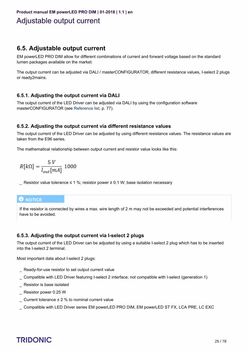
The mathematical relationship between output current and resistor value looks like this:
6.5.3. Adjusting the output current via I-select 2 plugsThe output current of the LED Driver can be adjusted by using a suitable I-select 2 plug which has to be insertedinto the I-select 2 terminal.
Most important data about I-select 2 plugs:
Example of calculation:
Resistor value tolerance ≤ 1 %; resistor power ≥ 0.1 W; base isolation necessary_
I NOTICE
If the resistor is connected by wires a max. wire length of 2 m may not be exceeded and potential interferenceshave to be avoided.
Ready-for-use resistor to set output current value_
Compatible with LED Driver featuring I-select 2 interface; not compatible with I-select (generation 1)_
Resistor is base isolated_
Resistor power 0.25 W_
Current tolerance ± 2 % to nominal current value_
Compatible with LED Driver series EM powerLED PRO DIM, EM powerLED ST FX, LCA PRE, LC EXC_

Product manual EM powerLED PRO DIM | 01-2018 | 1.1 | en
Constant Light Output and Over the lifetime
c 26 / 78
Example of calculation:
6.5.4. Adjusting the output current via ready2mainsready2mains can be used to configure both drivers with a separate communication interface as well as fixed outputdrivers.
The adjustment of the output current via ready2mains interface is done via the mains wiring (for LCA PRE, LC EXCand EM powerLED ST FX). The parameters can be adjusted either via ready2mains-capable configuration softwareor directly via the ready2mains programmer. Further information can be found in the Leaflet ready2mains (see Reference list, p. 77).
6.6. Constant Light Output and Over the Lifetime
6.6.1. DescriptionThe light output of an LED module reduces over the course of its life. The Constant Light Output functioncompensates for this natural decline by constantly increasing the output current of the LED Driver throughout its life.As a results, a virtually uniform light output is achieved at all times.
For configuration purposes the expected module-specific values for lifetime and residual luminous flux must bespecified. The output current is then controlled automatically on the basis of these values. The LED Driver typically starts with an output current ("Required Intensity") that corresponds to the expectedresidual luminous flux and calculates the increase in the value on the basis of the anticipated lifetime.
If the Over the Lifetime function is enabled, visual feedback is given as soon as the LED exceeds the expected LEDlamp life. If the expected LED lamp life is exceeded, the luminaire flashes for 2 seconds after being switched on.
R [kΩ] = 5 V / I_out [mA] x 1000_
Resistor value tolerance ≤ 1 %; resistor power ≥ 0.1 W; base isolation necessary_
When using a resistor value beyond the specified range, the output current will automatically be set to theminimum value (resistor value too big), respectively to the maximum value (resistor value too small)
_
I NOTICE
Unlike DALI which does not generate any additional tolerances in the output current, the tolerances are higherwhen using I-select 2 plugs.
I NOTICE
Please note that the resistor values for I-select 2 are not compatible with I-select (generation 1). Installation of anincorrect resistor may cause irreparable damage to the LED module(s).
Resistors for the main output current values can be ordered from Tridonic. Information can be found in the datasheet at "accessories" (see ).Reference list, p. 77

Product manual EM powerLED PRO DIM | 01-2018 | 1.1 | en
Constant Light Output and Over the lifetime
c 27 / 78
6.6.2. Commissioning
Procedure via the masterCONFIGURATOR
Activating the Constant Light Output function
Activating the Over the Lifetime function
Setting Required intensity and Expected LED life
Transferring existing values to a new LED DriverIf a LED Driver is replaced the existing parameter values can be transferred to the new LED Driver.
I NOTICE
To be able to adjust the parameters "Required intensity", "LED burning hours" and "Expected LED life" the"Advanced settings" must be activated. Further information can be found in the manual of the configuration software masterCONFIGURATOR (see
).Reference list, p. 77
Open dialog box "Tridonic-specific configuration"_
Click tab "CLO and OTL"_
Set drop-down menu "Constant intensity" to "enabled"_
Click "save"→ Changes are saved
_
Open dialog box "Tridonic-specific configuration"_
Click tab "CLO und OTL"_
Set drop-down menu "Visual feedback" to "enabled"_
Click "save"→ Changes are saved
_
Open dialog box "Tridonic-specific configuration"_
Click tab "CLO and OTL"_
Enter values in input fields "Required intensity" and "Expected LED life"_
Click "save"→ Changes are saved
_
Chose a LED Driver that is in the same room as the new LED Driver_
Open dialog box "Tridonic-specific configuration"_
Click tab "CLO and OTL"_
Note down the values for "Required intensity", "LED burning hours" and "Expected LED life"_

Product manual EM powerLED PRO DIM | 01-2018 | 1.1 | en
Constant Light Output and Over the lifetime
c 28 / 78
Replacing the LED moduleIf a LED module is replaced the parameter "LED burning hours" must be set to "0".
Further information can be found in the manual of the configuration software masterCONFIGURATOR (see ).Reference list, p. 77
...
Close dialog box "Tridonic-specific configuration"_
Chose the new LED Driver_
Open dialog box "Tridonic-specific configuration"_
Click tab "CLO and OTL"_
Take the noted values and enter them in the input fields "Required intensity", "LED burning hours" and"Expected LED life"
_
Click "save"→ Changes are saved
_
Open dialog box "Tridonic-specific configuration"_
Click tab "CLO and OTL"_
Delete value from input field "LED burning hours"→ CLO function is automatically restarted→ Changes are saved
_

Product manual EM powerLED PRO DIM | 01-2018 | 1.1 | en
Intelligent Temperature Guard
c 29 / 78
6.7. Intelligent Temperature Guard
6.7.1. DescriptionThe Intelligent Temperature Guard function provides protection against temporary thermal overloads therebypreventing an instant failure of the device or a possible long-term reduction of the nominal lifetime of the device.
As soon as a predetermined temperature is exceeded, the output power is reduced in small steps. This reductioncontinues until the LED Driver operates in a permitted temperature range. Since the power reduction is carried outin small steps, it is generally imperceptible to the user.
The following table shows the exact behaviour and parameters of the Intelligent Temperature Guard function for EMpowerLED PRO DIM in detail:
Parameter Description
Start of power reduction At maximum operating temperature≈ 10 °C above T temperature (exact value is device specific)c
Power reduction rate Every 2 minutes the digital dimming value is reduced by the value 1. from the followingThe resulting reduction in relative lighting level can be read
graph.
½ WARNING!
The T temperature is the maximum permitted temperature at the T point.c cOperating the LED Driver above the permitted T temperature is not compliant with relevant standards.cThe Intelligent Temperature Guard function does not replace the proper thermal design of the luminaire and doesnot enable the lighting to operate for lengthy periods of time in impermissible ambient temperatures.

Product manual EM powerLED PRO DIM | 01-2018 | 1.1 | en
Intelligent Temperature Guard
c 30 / 78
Power reduction method Analogue dimming (100 - 1 %)
Power reduction processand control
Power reduction is dependent on temperature:
Min. power level AC operation:
DC operation:
Shut-off behaviour No shut-off behaviour:Device will reduce power level as described at "Min. power level".
Automatic restart behaviour No automatic restart behaviour (because there is no shut off behaviour) Device stays at reached "Min. power level"
...
Power reduction continues if temperature still rises_
Power reduction stops if temperature does not rise anymore or if min. powerreduction is reached
_
Reduction up to 50 % if maximum operating temperature is exceeded_
Reduction up to 15 % if critical operating temperature is exceeded_
Reduction up to 50 % if maximum operating temperature is exceeded_
no further reduction, since critical operating temperature is not used in DCoperation→ 50 % is maximum reduction
_
I NOTICE
The standard setting for the dimming curve is logarithmic:If linear dimming curves are used the power reduction can be implemented differently.

Product manual EM powerLED PRO DIM | 01-2018 | 1.1 | en
Power-up fading
c 31 / 78
6.8. Power-up fading
6.8.1. DescriptionThe power-up fading function offers the opportunity to realise a soft start. The soft start will be applied at turning onthe mains and at starts by switchDIM. The function is programmed as a DALI fade time in the range from 0.7 to 16seconds and dims in the selected time from 1 % to the power-on level.
By factory default power-up fading is not active (0 seconds).
6.8.2. Commissioning
Procedure via the masterCONFIGURATOR
Further information can be found in the manual of the configuration software masterCONFIGURATOR (see ).Reference list, p. 77
...
Open dialog box "Tridonic-specific configuration"_
Click tab "Power-up Fading"_
Choose value from drop-down menu "Power-up Fading"_
Click "save"→ Changes are saved
_

Product manual EM powerLED PRO DIM | 01-2018 | 1.1 | en
Power-up fading
c 32 / 78
6.9. ready2mains
6.9.1. Description ready2mains uses the mains cable to transmit information: easily, reliably and professionally.
ready2mains can be used to configure both drivers with a separate communication interface as well as fixed outputdrivers. The configuration saves time and is very flexible. ready2mains reduces production costs and also reducespossible sources of error.
ConfigurationThe ready2mains interface can be used to configure the main parameters of LED Drivers via the mains wiring (LEDoutput current and CLO for LCA PRE and EM powerLED PRO DIM). These parameters can be adjusted either viaready2mains-capable configuration software or directly via the ready2mains programmer (output current only).Further information can be found in the Leaflet ready2mains (see ).Reference list, p. 77
...
Easy configuration of luminaires_
Simple integration in existing test setups_

Product manual EM powerLED PRO DIM | 01-2018 | 1.1 | en
Adjustable output current
c 33 / 78
6.10. Adjustable output current
6.10.1. DescriptionIf the EM powerLED PRO DIM switches to emergency operation in case of a power failure, the device will detect theforward voltage of the connected LED modules and set the correct LED current. Setting a constant output powerensures maximum light output in emergency mode for the specified operating time.
An EM powerLED PRO DIM with 3 or 4 watts output power operates the connected LED modules with said outputpower. For this purpose, the device detects the connected LED forward voltage, and adjusts the LED forwardcurrent to the appropriate value, resulting in an output power of 3 or 4 watts.
EM powerLED PRO DIM 103 EM powerLED PRO DIM 104
Max. output power: 3 W Max. output power: 4 W
6.10.2. CalculationFormel: P = U * I
P = U * I
Emergency output power:Given by the EM powerLEDPRO DIM type
LED forward voltage:Detected by the EMpowerLED PRO DIM
LED forward current:Automatically adjusted by the EMpowerLED PRO DIM
I NOTICE
At the lowest range of permissible forward voltage, the efficiency may be slightly lower. In this case the outputpower is also slightly lower.

Product manual EM powerLED PRO DIM | 01-2018 | 1.1 | en
Addressing system EZ easy addressing
c 34 / 78
Example
Given:
Wanted:
Result:
Different battery cell numbers offer flexibility in the available emergency output power - 3 cells and 4 cells for LEDmodules from 20 V to 50 V forward voltage.The LED current in emergency mode is automatically adjusted by the EM powerLED PRO DIM based on the totalforward voltage of the LED modules connected and the associated battery.
Device typesForward voltagerange SELV Number of battery cells
EM powerLED PRO DIM103
20-50 V SELV < 60 V 3 cells for lower light output in emergencyoperation
EM powerLED PRO DIM 20-50 V SELV < 60 V 4 cells for higher light output in emergencyoperation
LED forward voltage: 45 V (chosen as an example)_
LED forward current (at 45 V): 60 mA (taken from diagram EM powerLED PRO DIM 103)_
Emergency output power?_
Emergency output power:P = U * I = 45 V * 60 mA = 3 W
_
I NOTICE
There is a separate chapter that describes how the light output in emergency operation can be determined (seechapter ).Determining light output in emergency operation, p. 51

Product manual EM powerLED PRO DIM | 01-2018 | 1.1 | en
Addressing system EZ easy addressing
c 35 / 78
6.11. Addressing function EZ easy addressing
In a DALI installation addresses are assigned to the control gear. The EM powerLED PRO DIM operates with onlyone DALI address for both mains and emergency operation (Multi Device Type according to DALI standard). Afterthe automatic addressing it is necessary to assign the physical address in the building plan to the correspondingDALI address. With the patented addressing function "EZ easy addressing" this address assignment can beperformed in a simple way.
The addressing function "EZ easy addressing" is activated by sending the DALI identification command for singlebattery supplied emergency lighting (device type 1, command number 240). As a result, the bi-colour status LEDs ofall the devices in the selected DALI circuit will start to blink. The addresses of the devices can be calculated by thesequence of blinking signals that the devices emit.
...
A 3 second pause marks the beginning of a sequence._
After this, the status LED blinks for six times in a row:A blinking green light indicates the value "1", a blinking red light indicates the value "0". Starting with thehighest value, the sequence of colours can be noted.
_
The result is a 6-bit binary code, which can be converted into a decimal DALI address between 0 and 63 andcan be entered in the light installation plan.
_

Product manual EM powerLED PRO DIM | 01-2018 | 1.1 | en
Addressing system EZ easy addressing
c 36 / 78
The following table shows two examples of blinking light sequences and how they are converted into a decimaladdress is:
Sequence of blinking lights Address
32 16 8 4 2 1
16+1=17
8+4=12
Green blinking => Value 1 Red blinking => Value 0
Further information about the EZ addressing tool (article number: 89899836) can be found in the product catalogue(see ).Reference list, p. 77
In the DALI standard version 2, a new DALI identification command (command number 37) for control gear isdescribed. Using this identification command, the LED module switches back and forth between the minimum andthe maximum light value. Both DALI identification commands are supported by the EM powerLED PRO DIM. TheDT1 command (command number 240) has priority over the new identification command (command number 37).Both commands operate independently.
...
I NOTICE
The Android app "Emergency ADDRESSING Decoder" can be used to convert blinking light sequences into adecimal address. The app can be downloaded at
.https://play.google.com/store/apps/details?id=net.gmx.royder.knight.EZ_easyADRESSING
I NOTICE
The LED modules are switched off at the beginning of the addressing function EZ easy addressing. They areturned back on, when leaving this function.

Product manual EM powerLED PRO DIM | 01-2018 | 1.1 | en
Settings for emergency tests
c 37 / 78
7. Settings for emergency tests7.1. Time intervals between emergency testsThe timing for the individual tests is defined by the DALI parameters INTERVAL time and DELAY time.
Both values are stored in the device's internal memory. The values can be changed by connecting a DALI bus andby sending appropriate DALI commands or can also be deactivated, i.e. reset to zero. This provides different settingoptions which are crucial for implementing different test systems.
...
INTERVAL time:This determines the time interval in which function and duration tests are carried out. The factory presetsspecify that the function test is performed every 7 days and the duration test every 52 weeks. Typically thesame INTERVAL time is assigned to all the connected luminaires. If the INTERVAL time is reset to zero this means that the test is no longer automatically initiated by thedevice but only via the connected control system.
_
DELAY time:This determines the delay for initiating the tests between the individual luminaires. The factory default isDELAY time = 0. This means that there is no delay and all the luminaires are tested at the same time. Byassigning a DELAY time to an individual luminaire the test for that luminaire will be delayed by theappropriate value. The delay is based on the point in time when the device was first connected to the powersupply.
_

Product manual EM powerLED PRO DIM | 01-2018 | 1.1 | en
Settings for emergency tests
c 38 / 78
7.2. Type of test system: DALI-controlled or selftest modeThere are two types of test system:
The following table gives an overview of the test systems and setting options:
Test system Trigger Test times Requirements Comments
DALI-controlled
Testtriggeredby theDALIcontrolsystem
Test time and interval arestored in the DALI controlsystem
Selftest mode wasdeactivated by resettingthe DELAY time andINTERVAL time in theemergency lighting unit tozero
Tests are onlyperformed if anappropriatecommand isreceived by theemergency lightingunit.
Selftestmode
Testtriggeredbyemergencylightingunit
The time for the function test(time and day) corresponds tothe time when the emergencylighting unit was first connectedto the power supply.
The time for the duration test(only time) is determined by theadaptive test mode of theemergency lighting unit (see
).Adaptive test mode, p. 39
The time between the tests isdetermined by the INTERVALtime.
The time between the individualluminaires is determined by theDELAY time.
The DELAY time andINTERVAL time areprogrammed toappropriate values andare NOT reset to zero.
The DELAY time andINTERVAL time canbe changed byappropriatecommands via theDALI bus.
Centrally controlled and monitored (DALI-controlled)_
Decentrally controlled and monitored (selftest mode)_
I NOTICE
As soon as the preset parameters are reset to zero, tests are only carried out on request by the DALI controlsystem.If the DALI bus is interrupted, the EM powerLED PRO DIM does not go back to selftest mode.

Product manual EM powerLED PRO DIM | 01-2018 | 1.1 | en
Settings for emergency tests
c 39 / 78
7.3. Adaptive test modeAdaptive test mode sets the time for the duration test to a time of minimum risk and minimum presence.
This is achieved by monitoring the switched phase of the lighting. This tells the emergency lighting unit which timesthe lighting is switched off (i.e. no one is in the room) and the unit stores these times. If non-presence of more thanfive hours is detected the start time for the duration test is set to one hour after the start of the non-presence time.
Example: A room is not used between 8 pm and 6 am. The lights are therefore switched off. The duration test will thereforebegin at 9 pm. This provides a certain buffer before the start and after the end of the duration test, and the batteriescan be recharged after the duration test before the room is in use again.
Room usage is monitored on a monthly basis and the time for the duration test is constantly adjusted. This allowsfor seasonality in room usage to be taken into account.
If a suitable time cannot be found (perhaps because the room is in use round the clock) the duration test isperformed at the time set during startup (this is the time when the emergency lighting unit was first connected to thepower supply). If subsequently a suitable period is found the time for the duration life test will be suitably adapted.
If none of this is successful because the startup time is unsuitable and no other suitable period can be found, thetime for the duration test can be set manually (see ).Setting the test time, p. 40
7.4. Functionality of the test switchThe optional test switch enables you to make a series of settings manually.
7.4.1. Starting the function tests
I NOTICE
DALI communication with a connected battery is only possible after a mains reset.
I NOTICE
The test switch can remain permanently connected and used as a startup tool.
A short press on the button (0.15 - 1 s) starts a function test lasting 5 seconds. → The indicator LED flashes GREEN.→ The result of the function test is displayed on the two-colour indicator LED.
_

Product manual EM powerLED PRO DIM | 01-2018 | 1.1 | en
Intelligent multilevel charging system
c 40 / 78
7.4.2. Starting the test mode
7.4.3. Setting the test timeThe time and day for the function and duration test is stored in the internal timer. To change the test time the timerneeds to be reset. All the test times previously stored will be deleted and replaced by the time of resetting.
Depending on whether the timer is to be reset for one luminaire or for multiple luminaires, there are two differentmethods:
Setting the test time for one luminaire
Setting the test time for all the light sources in an emergency lighting circuit
7.5. Intelligent multilevel charging systemThe multilevel charging system is used for minimising charging times while maximising battery life. During normalfunctional mains operation the module charges the batteries using a specially developed charging algorithm.
A longer press on the button (1 - 10 s) switches the light sources to emergency mode but does not perform afunction test.→ The indicator LED goes off for 1 second and then on for the rest of the time (maximum of 9 seconds).
_
I NOTICE
Resetting the timer deactivates the . Because of this the test time is no longer adaptedadaptive test mode, p. 39to the room usage of the building. The function test and duration test is always carried out at the time of resetting.
Holding down the button (> 10 s) resets the timer.→ The indicator LED goes off for 1 second and then shows GREEN and goes off again after 10 seconds.→ The indicator LED going off after 10 seconds confirms that the timer has been successfully reset (to thecurrent time).
_
Switching the unswitched power supply for an emergency lighting circuit on and off 5 times within 60 secondsresets the timers for all the light sources in the emergency lighting circuit.
_
Initial charge mode: 20 hours of high charging current at the start to prepare the new battery cells and fully charge them.
_
Trickle charge mode: Continuous low charge to maintain battery output and reduce battery temperature.
_
Fast charge mode: Automatic adjustment of the charge time ensures minimal overcharging:
_
10 or 15 hours of rapid charge after a full discharge._
Shorter charge time after only a partial discharge._

Product manual EM powerLED PRO DIM | 01-2018 | 1.1 | en
Intelligent multilevel charging system
c 41 / 78
When the permanent power supply is switched on for the first time the EM powerLED PRO DIM starts to charge thebatteries for 20 hours in fast charge mode. This 20-hour preparatory charge ensures that the new batteries arecompletely charged before being used. The 20-hour recharge is also used if a new battery is connected or if thedevice leaves the Rest mode (see ).Rest mode, Inhibit mode and Relight command, p. 42
At the end of the 20-hour charge the module automatically switches to trickle charge mode. This ensures that thebatteries remain at optimum charge levels and avoids any overheating due to overcharging.
After a power outage and subsequent emergency mode the EM powerLED PRO DIM recharges the batteries in fastcharge mode. However, the charge time is set so that only the power consumed during emergency mode isreplaced. If emergency mode did not last as long as the prescribed operating time the charging time will be reduced.If emergency mode extended for the full operating time the charging time will be 10 hours for modules with anoperating time of 1 hour, and 15 hours for modules with an operating time of 2 and 3 hours. Once the batteries arefully charged again the module automatically switches to trickle charge mode.
In trickle charge mode the battery status is continually monitored to ensure that the charging currents and batteryvoltages remain within the specified limits. If these limits are exceeded error status flags are set for monitoring withthe aid of a suitable control system. The status LED also shows such faults locally.
If a duration test is required while the battery is not yet fully charged the test will be postponed until charging iscomplete. This prevents a duration test from being carried out with a battery that is not fully charged.
If the power supply fails during rapid charging the module will power the lamp immediately in emergency mode foras long as the charge in the batteries will allow.
...
Shorter charge time after only a partial discharge._
NiCd batteries are charged with a constant charging current in trickle charge mode_
NiMH batteries are charged with a pulsed charging current in trickle charge mode_
I NOTICE
A partially charged battery is defined as one for which the charger is operating in fast charge mode. A fully charged battery is defined as one for which the charger is operating in trickle charge mode. Theappropriate bit in the internal memory (command number 253 Bit 3) is set.

Product manual EM powerLED PRO DIM | 01-2018 | 1.1 | en
Rest mode and Relight function
c 42 / 78
7.6. Rest mode, Inhibit mode and Relight commandEmergency operation is automatically started when the mains supply is switched off. If the Rest mode is activated,the discharging of the battery will be minimized by switching off the LED output.
Rest mode can be used during short periods of time when a building is completely unoccupied and the mains supplyis to be switched off intentionally, for example during a holiday period. Using Rest mode prevents a full dischargeand possible damages to the batteries during these times.
Rest mode has to be activated by a competent person. Activation is only possible after the mains supply has beenswitched off. Contrary to this, if the Inhibit mode has been activated in advance, Rest mode will be automaticallyswitched on if the mains supply is switched off.
By sending the Relight command both modes, Rest mode and Inhibit mode, will be deactivated. The emergency unitwill switch back to the previous operating mode. If it has been in Rest mode, it will switch back to emergency mode,if it has been in Inhibit mode, it will switch back to charging mode
For all the different changes, activating Rest mode and Inhibit mode and sending the Relight command, DC voltagepulses of different lengths are used. The table at gives an overview ofSwitching between operating modes, p. 44all the operating modes.
7.6.1. Activate Rest mode Rest mode is activated as follows:
½ CAUTION!
Even in Rest mode there is self discharge current and an extremely small level of discharge current flowing fromthe batteries. If the batteries remain in Rest mode for prolonged periods of time this can lead to deep dischargeand potential damage. Further information can be found in the data sheet of the batteries (see Reference list, p.
).77
Disconnect power supply_
Apply DC voltage pulse at the two terminal points "REST/L" and "REST/N"_The signal of must have an amplitude 9.5 - 22.5 V with a pulse length of 150 - 1,000 ms_
The polarity of the voltage pulse does not matter_
I NOTICE
Rest mode cannot be activated as long as the power supply hasn't been disconnected. The maximum number of emergency units on one bus is 100 pieces with a maximum recommended cable length
of 1000 metres. Rest mode voltage can be applied across all emergency modules (parallel connection).

Product manual EM powerLED PRO DIM | 01-2018 | 1.1 | en
Rest mode and Relight function
c 43 / 78
7.6.2. Deactivate Rest mode via Relight commandBy sending the Relight command the Rest mode is deactivated. The emergency unit will switch back to emergencymode.To deactivate Rest mode via Relight command, proceed as follows:
7.6.3. Activate Inhibit modeInhibit mode is activated as follows:
For further information see .Indicator LED, p. 46
7.6.4. Automatically switch from Inhibit mode to Rest modeThe emergency unit automatically switches from Inhibit mode to Rest mode if the following conditions are met:
Apply DC voltage pulse at the two terminal points "REST/L" and "REST/N"_The signal of must have an amplitude 9.5 - 22.5 V with a pulse length of 1,001 - 2,000 ms_
The polarity of the voltage pulse does not matter_
I NOTICE
Reapply the power supply does also deactivate Rest mode. In this case, the device switches from Rest mode tocharge mode.
Make sure that the mains supply is switched on_
Apply DC voltage pulse at the two terminal points "REST/L" and "REST/N"
→ Emergency unit switches to Inhibit mode→ Inhibit mode is active for a duration of 15 minutes→ Inhibit mode is indicated by indicator LED (double pulsing GREEN)
_The signal of must have an amplitude 9.5 - 22.5 V with a pulse length of 150 - 1,000 ms_
The polarity of the voltage pulse does not matter_
I NOTICE
The inhibit mode must be activated before the mains supply is switched off.
Inhibit mode has been activated -and-_
Within 15 minutes after activation, the mains supply is switched off_

Product manual EM powerLED PRO DIM | 01-2018 | 1.1 | en
Rest mode and Relight function
c 44 / 78
7.6.5. Automatically deactivate Inhibit modeInhibit mode is automatically deactivated and the emergency unit switches back to charging mode if the followingconditions are met:
7.6.6. Deactivate Inhibit mode via Relight commandBy sending the Relight command the Inhibit mode is deactivated. The emergency unit will switch back to chargingmode.To deactivate Inhibit mode via Relight command, proceed as follows:
7.6.7. Switching between operating modesThe device has four different operating modes (Standby/Charge mode, Emergency mode, Rest mode and Inhibitmode). Depending on the initial mode and the length of the applied DC voltage pulse the device switches betweenthese operating modes. The following table gives an overview:
Applied pulselength Charging mode
Emergencymode Rest mode Inhibit mode
150 - 1,000 ms Switches to Inhibitmode
Switches to Restmode
- -
1,001 - 2,000 ms(Relight
command)
- - Switches to Emergencymode
Switches to chargingmode
...
Within 15 minutes after activation, the mains supply is switched offnot_
Apply DC voltage pulse at the two terminal points "REST/L" and "REST/N"_The signal of must have an amplitude 9.5 - 22.5 V with a pulse length of 1,001 - 2,000 ms_
The polarity of the voltage pulse does not matter_

Product manual EM powerLED PRO DIM | 01-2018 | 1.1 | en
Prolong time
c 45 / 78
7.7. Prolong timeThe command "Store prolong time" (command number 239) allows the EM powerLED PRO DIM to continueemergency operation after restoration of the power supply. This time can be set in 30 second steps. The maximumvalue is 127.5 minutes. The device leaves this continued emergency operation after the set time has expired or assoon as the low voltage battery cut off level has been reached (discharge protection), that is, when the totaloperating time has been exceeded.
The prolong time can be set by the DALI controller.
...

Product manual EM powerLED PRO DIM | 01-2018 | 1.1 | en
Indicator LED
c 46 / 78
7.8. Indicator LEDSystem status is locally indicated by a bi-colour indicator LED.
LED indication Status Description
Permanent GREEN Standby/Chargemode, SystemOK
Mains operation, battery is charged
Fast flashing GREEN(0,1 s on - 0,1 s off)
Function testunderway
Slow flashing GREEN(1 s on - 1 s off)
Duration testunderway
Double pulsingGREEN
Inhibit mode isactivated
The Inhibit mode makes it possible to set the emergency mode to"inhibited"; in this mode, the power can be turned off without switchingto emergency mode.
The Inhibit mode is activated by sending the inhibit command(command number: 225), while the modules are still connected tomains. Just as in Rest mode, the device does not support the Relightcommand (command number: 226). After a break of 15 minutes, theinhibit mode is automatically reset.
Permanent RED Lamp failure Open circuit -or- Short circuit -or- LED failure
Fast flashing RED(0,1 s on - 0,1 s off)
Charging failure-or- device failure
Incorrect charging current
I NOTICE
After an exchange of the LED module, the RED light of the indicatorLED remains on and the lamp failure flag remains set until ascheduled function test or a "maintenance" function test requestedby the control system has been successfully completed. The LEDmodule's mains operation does reset the lamp failure flag.
I NOTICE
After an exchange of the device in a DALI-controlled system it isnecessary to address the LED Driver and reset the DELAY timeand INTERVAL time.

Product manual EM powerLED PRO DIM | 01-2018 | 1.1 | en
Indicator LED
c 47 / 78
Slow flashing RED(1 s on - 1 s off)
Battery failure Battery failed duration test or function test -or- Battery is defect -or-Incorrect battery voltage
GREEN and RED off Batteryoperation
Emergency mode: Mains disconnected -or- mains failure
RED and GREENflashing alternating
Addressingfunction EZeasyaddressing
The addresses of the devices can be calculated by the sequence offlashing signals that the devices emit (see Addressing function EZ
).easy addressing, p. 35
...
I NOTICE
After an exchange of the battery the indicator LED switches toGREEN to indicate satisfactory charging.
The battery failure flags will only be reset after a successfulcompletion of a "maintenance" duration test, though. This"maintenance" duration test can only be performed if the batteriesare fully charged. For this, new batteries must have completed the20-hour initial charge mode (see Intelligent Multilevel battery
).system, p. 40
I NOTICE
If a lamp error was detected at an emergency test and then corrected (by changing the lamp for example), theerror indication can only be corrected by a renewed emergency test. Switching to mains operation does not resetthe error indication.

Product manual EM powerLED PRO DIM | 01-2018 | 1.1 | en
Functions in emergency operation
c 48 / 78
8. Functions in emergency operationOverview of the main functions in emergency operation:
Area Function
DALI emergency functionality DALI V2 DT1
Test function, p. 37 Automatic function and duration test Centralized testactivation via DALI
Function test (interval) Adjustable via DALI
Duration test (interval) Adjustable via DALI
Rated duration Adjustable to 1, 2 or 3 hours (1)
Adjustable on the device via DIP switch
Status display Via two-colour indicator LED, p. 46
Battery charge system Intelligent multilevel charging system, p. 40
Intermittent charging (pulse charging) forNiMH batteries
Adjustment of output current, p. 25 Automatic adjustment by device
DALI addressing and identification Addressing function EZ easy addressing, p. 35
Commissioning Automatic
Rest mode, Inhibit mode and Relightcommand, p. 42
Activation Via DALI
Prolong time, p. 45 Adjustable in 30-second steps to amaximum of 127.5 minutes
Via DALI
(1) Special case: 2-hours rated durationThe first duration test will take 120 minutes, following duration tests are rated with 90 minutes. If the battery is
disconnected or replaced, the next duration test will again be rated with 120 minutes.

Product manual EM powerLED PRO DIM | 01-2018 | 1.1 | en
Typical Installation
c 49 / 78
disconnected or replaced, the next duration test will again be rated with 120 minutes.
9. A typical installation9.1. Initial startupAfter initial connection of the permanent power supply and after connection of the batteries to the EM powerLEDPRO DIM the module starts to charge the batteries with the initial high charging current for 20 hours (initial chargemode).
Since the DELAY time is preset to zero at the factory, the EM powerLED PRO DIM tries to perform an initial functionand duration test (commissioning test) as soon as connection to the power supply is made. Since at this time thebatteries are not yet adequately charged the EM powerLED PRO DIM postpones the commissioning test.
Generally, the batteries will be fully charged within 24 hours and the commissioning test can then be carried out.The operation time corresponds to the preset value.
If the power supply is interrupted before the end of the 20 hours of continuous initial charging the initial chargingprocess will be completely restarted and the commissioning test postponed accordingly.
9.2. Installation without a control systemIf a control system is not connected, the EM powerLED PRO DIM will carry out all further tests in accordance withthe parameters preprogrammed in the internal memory (INTERVAL time and DELAY time), i.e. a function test everyseven days and a duration test every 52 weeks.
Function tests are performed irrespective of the charge status of the battery, duration tests are only performed if thebattery is fully charged.
If a duration test is required while the battery is not yet fully charged the test will be postponed until charging iscomplete. This prevents a duration test from being carried out with a battery that is not fully charged (see Intelligent
).multilevel charging system, p. 40
I NOTICE
If the INTERVAL time was reset to zero by the control system during the addressing, the commissioning test isperformed only after the initial commissioning. If mains supply and batteries are disconnected and thenreconnected at a later time, this does not trigger a renewed commissioning test. If the battery is replaced, it isexpected that the control system requests the test.

Product manual EM powerLED PRO DIM | 01-2018 | 1.1 | en
Typical Installation
c 50 / 78
...
I NOTICE
If the INTERVAL time has not been reset to zero, the procedure after a battery replacement is the same as duringinitial commissioning:The batteries are charged for 20 hours, after that a commissioning test is performed (see Intelligent multilevel
).charging system, p. 40
I NOTICE
A partially charged battery is defined as one for which the charger is operating in fast charge mode. A fully charged battery is defined as one for which the charger is operating in trickle charge mode. Theappropriate bit in the internal memory (command number 253 Bit 3) is set.

Product manual EM powerLED PRO DIM | 01-2018 | 1.1 | en
Determining light output in emergency operation
c 51 / 78
1.
2.
3.
10. Determining light output in emergency operationTo determine the light output in emergency operation the following parameters are crucial:
LED forward voltage (total forward voltage of all connected LED modules)
LED current in emergency operation
Light output in emergency operation
10.1. Parameter 1: LED forward voltage
10.1.1. Total forward voltage of all LED modulesThe forward voltage of a single LED module can be found in the data sheet. When calculating the total forwardvoltage of all LED modules, series and parallel circuits must be handled differently:
Series circuit Parallel circuit
The values of the individual LED modules aresummed up.
The total value is the same as the value of a single LEDmodule
...
The total forward voltage of all connected LED modules must be within the forward voltage range ofthe EM converterLED PRO DIM.
_

Product manual EM powerLED PRO DIM | 01-2018 | 1.1 | en
Parameter 1: LED forward voltage
c 52 / 78
10.1.2. Example 1: 1 LED module DLE
Given:
Wanted:
Result:
...
Forward voltage DLE: (taken from data sheet)24.2 V_
Total forward voltage of all LED modules in emergency operation_
The total forward voltage of all LED modules is because there is only 1 LED module.24.2 V_

Product manual EM powerLED PRO DIM | 01-2018 | 1.1 | en
Parameter 1: LED forward voltage
c 53 / 78
10.1.3. Example 2: 4 LED module DLE in parallel
Given:
Wanted:
Result:
...
Forward voltage DLE: (taken from data sheet)24.2 V_
Total forward voltage of all LED modules?_
The total forward voltage of all LED modules is 24.2 V (no addition of the values in a parallel circuit)._
I NOTICE
As Example 2 shows, parallel circuits make it possible to use multiple LED modules where the forward voltagedoes not add up.

Product manual EM powerLED PRO DIM | 01-2018 | 1.1 | en
Parameter 2: LED current
c 54 / 78
10.2. Parameter 2: LED currentEach EM powerLED PRO DIM has a specific current/voltage characteristic. The corresponding current/voltagecurve can be found in the datasheet:
EM powerLED PRO DIM 103 50V EM powerLED PRO DIM 104 50V
Knowing the total forward voltage of all LED modules, the value for the LED current can be read from thecurrent/voltage curve:
The value of the LED current lies within this range. The effective value depends on tolerances.
...
Mark the value of the total forward voltage of all LED modules on the x-axis of the graph_
From that point move up vertically → The crossing points with the two curves define a range of values.
_

Product manual EM powerLED PRO DIM | 01-2018 | 1.1 | en
Parameter 2: LED current
c 55 / 78
10.2.1. Example 1: 1 LED module DLE
Given:
Wanted:
Result:Figure: Determining LED current for EM converterLED PRO DIM 103 50V
...
Total forward voltage of all LED modules: 24.2 V (calculated before)_
LED current?_
The two crossing points are at around 85 mA (minimum value) and 111 mA (maximum value)._
The effective value of the LED current is between these two values._

Product manual EM powerLED PRO DIM | 01-2018 | 1.1 | en
Parameter 3: Light output in emergency operation
c 56 / 78
10.3. Parameter 3: Light output in emergency operationThe ratio between emergency operation and normal operation is the same for light output and LED current. Thevalues for normal operation can be found in the LED module data sheet, the value for the LED current in emergencyoperation can be found in the data sheet (see example above).
With this equation the light output in emergency operation can be isolated and calculated:
10.3.1. Example 1: 1 LED module DLE
Given:
Wanted:
Result:
...
LED current in emergency operation: approx. 85 mA (minimum value) and approx. 111 mA (maximum value)(taken from the previous example, see ) Example 1: 1 LED module DLE, p. 55
_
LED current in mains operation 750 mA (taken from data sheet DLE G3 2000 lm, Article number: 89600574)_
Light output in mains operation: 2,100 lm (taken from data sheet DLE G3 2000 lm, Article number: 89600574)_
Light output in emergency operation?_
Minimum light output in emergency operation = 85 mA / 750 mA * 2,100 lm = 238 lm_
Maximum light output in emergency operation = 111 mA / 750 mA * 2,100 lm = 310.8 lm_

Product manual EM powerLED PRO DIM | 01-2018 | 1.1 | en
Compatibility between LED module and LED Driver
c 57 / 78
11. Compatibility between LED module and LED DriverThere are two stages involved in the check for compatibility between the LED module and the LED Driver.
11.1. Comparison of data sheet values with a 5-point guidelineDifferent values for the two components need to be considered when comparing the data sheets. The followingtable shows which values are involved and which requirements they must meet.
Comparisonof…
Value inLED
module Value inLED Driver Detailed procedure
(1) Current Imax = Outputcurrent
continue... → ↓
Max. DCforwardcurrent
≥ Outputcurrent +tolerances
...
The requirements for operating together can be checked by comparing the data sheets_
Subsequent practical tests can ensure that there are no unexpected problems during actual operation_
Determine forward current of LED module_
Check whether LED Driver can be operated with the sameoutput current
_
Check whether max. DC forward current of LED module isgreater than or equal to output current of LED Driver(including tolerances)
_
½ CAUTION!
The max. DC forward current can be temperature dependent!
Refer to the derating curve of the LED module data sheet.

Product manual EM powerLED PRO DIM | 01-2018 | 1.1 | en
Compatibility between LED module and LED Driver
c 58 / 78
Comparisonof…
Value inLED
module
Value inLEDDriver Detailed procedure
(2) Voltage Min. forwardvoltage
> Min. outputvoltage
Max.forwardvoltage
< Max.outputvoltage
Min. forwardvoltage
@ min. dimlevel
> Min. outputvoltage
(3) LF currentripple
Max.permissibleLF current
ripple
≥ Output LFcurrentripple(<120Hz)
(4) Max. peakcurrent
Max.permissible
peak current
> Max.outputcurrentpeak
(5) Power (pertinent formulti channelcontrol gear)
Min. powerconsumption
> Min. outputpower
Check whether voltage range of LED module iscompletely within the voltage range of LED Driver
_
½ CAUTION!
!The forward voltage is temperature dependent Refer to the Vf/t diagram in the data sheet.p
I NOTICE
To ensure full dimming performance the forward voltage ofthe LED module at min. dim level must be greater than orequal to the min. output voltage of the driver.
Determine the forward voltage of the LED module atlowest dim level
_
In case there is no data available for the LED module atlowest dim level: take the min. forward voltage minus 20% as an approximation
_
Check whether the forward voltage of the LED module isgreater than or equal to the min. output voltage of thedriver
_
Check whether max. permissible LF current ripple ofLED module is greater than or equal to output LF currentripple of LED Driver
_
Check whether max. permissible peak current of LEDmodule is greater than max. output current peak of LEDDriver
_
Check whether power range of LED module iscompletely within output power range of LED Driver
_

Product manual EM powerLED PRO DIM | 01-2018 | 1.1 | en
Compatibility between LED module and LED Driver
c 59 / 78
Max. powerconsumption
< Max.outputpower
...

Product manual EM powerLED PRO DIM | 01-2018 | 1.1 | en
Compatibility between LED module and LED Driver
c 60 / 78
11.2. Application of the 5-point guidelineThe compatibility check with the 5-point guideline is shown here using two examples.
11.2.1. Example 1
Comparison data for LED Driver
LED Driver
Designation LCI 20W 350mA-900mA TOP C
Manufacturer TRIDONIC
Data sheet values of LED Driver
Output current 500 mA
Output current tolerance ± 5 %
Min. output voltage 18 V (1)
Max. output voltage 40 V (1)
Output LF current ripple ± 2 %
Max. output current peak 600 mA
Output power 20.0 W
(1) Values at 500mA

Product manual EM powerLED PRO DIM | 01-2018 | 1.1 | en
Compatibility between LED module and LED Driver
c 61 / 78
Comparison data for LED module
LED module
Designation Fictitious LED module
Manufacturer Other manufacturer
Data sheet values of LED module
Forward current 500 mA
Max. DC forward current 1,050 mA
Typ. forward voltage 33 V +/-10 % (1)
Min. forward voltage 29.7 V (1)
Max. forward voltage 36.3 V (1)
Max. permissible LF current ripple 100 mA
Max. permissible peak current 1,500 mA
Power draw 16.4 W
(1) Values at 500mA
Questions
...
Are the two components mutually compatible?_
Can the required luminous flux of 1,510 lm be achieved with this combination?_

Product manual EM powerLED PRO DIM | 01-2018 | 1.1 | en
Compatibility between LED module and LED Driver
c 62 / 78
ProcedureComparison of data sheet values
Comparison of…
Value inLED
module
Valuein LEDDriver Result Explanation
(1) Current 500 mA = 500 mA
1,050mA
≥ 525mA
(2) Voltage 29.7 V > 18 V
36.3 V < 40 V
(3) LF current ripple 100 mA > 10.5mA
(4) Max. peak current 1,500 mA > 600mA
(5) Power 16.4 W < 20.0 W
ResultAll the values meet the requirements. The components are mutually compatible.
To produce a luminous flux of 1,510 lm the LEDmodule must be operated with a forward currentof 500 mA.
_
The LED Driver can be set so that it deliversprecisely this value of 500 mA as the outputcurrent (with a resistance of 49.90 kΩ).
_
The output current of the LED Driver includingtolerances (500 mA + 5 % = 525 mA) is lessthan or equal to the max. DC forward current ofthe LED module (1,050 mA).
_
The voltage range of the LED module (29.7 V -36.3 V) lies completely within the voltage rangeof the LED Driver (18 V - 40.0 V).
_
The Output LF current ripple (2 % of outputcurrent plus tolerances: [500 mA + 5 %] x 0.02= 10.5 mA) of the LED Driver is less than themax. permissible LF current ripple of the LEDmodule (100 mA).
_
The max. output current peak of the LED Driver(500 mA + 20 % = 600 mA) is less than themax. permissible peak current with which theLED module can be operated (1,500 mA).
_
The power draw of the LED module (16.4 W) isless than the output power of the LED Driver(20.0 W).
_

Product manual EM powerLED PRO DIM | 01-2018 | 1.1 | en
Compatibility between LED module and LED Driver
c 63 / 78
11.2.2. Example 2
Comparison data for LED Driver
LED Driver
Designation LCI 20W 350mA-900mA TOP C
Manufacturer TRIDONIC
Data sheet values of LED Driver
Output current 500 mA
Output current tolerance ± 5 %
Min. output voltage 18 V (1)
Max. output voltage 40 V (1)
Output LF current ripple ± 2 %
Max. output current peak 600 mA
Output power 20.0 W
(1) Values at 500mA

Product manual EM powerLED PRO DIM | 01-2018 | 1.1 | en
Compatibility between LED module and LED Driver
c 64 / 78
Comparison data for LED module
LED module
Designation Fictitious LED module
Manufacturer Other manufacturer
Data sheet values of LED module
Forward current 500 mA
Max. DC forward current 1,050 mA
Typ. forward voltage 39.5 V +/-10 % (1)
Min. forward voltage 35.55 V (1)
Max. forward voltage 43.45 V (1)
Max. permissible LF current ripple 100 mA
Max. permissible peak current 1,500 mA
Power draw 19.75 W
(1) Values at 500mA
Questions
...
Are the two components mutually compatible?_
Can the required luminous flux of 1,800 lm be achieved with this combination?_

Product manual EM powerLED PRO DIM | 01-2018 | 1.1 | en
Compatibility between LED module and LED Driver
c 65 / 78
ProcedureComparison of data sheet values
Comparison of…
Value inLED
module
Valuein LEDDriver Result Explanation
(1) Current 500 mA = 500 mA
1,050mA
≥ 525mA
(2) Voltage 35.55 V > 18 V
43.45 V < 40 V
(3) LF current ripple 100 mA > 10.5mA
(4) Max. peak current 1,500 mA > 600 mA
(5) Power 19.75 W < 20.0 W
ResultOne of the values meet the requirements. The components are mutually compatible.does not not
...
To produce a luminous flux of 1,800 lm the LEDmodule must be operated with a forward currentof 500 mA.
_
The LED Driver can be set so that it deliversprecisely this value of 500 mA as the outputcurrent (with a resistance of 49.90 kΩ).
_
The output current of the LED Driver includingtolerances (500 mA + 5 % = 525 mA) is lessthan or equal to the max. DC forward current ofthe LED module (1,050 mA).
_
The voltage range of the LED module (35.55 V -43.45 V) is within the voltage range of thenotLED Driver (18 V - 40.0 V)
_
The Output LF current ripple (2 % of outputcurrent plus tolerances: [500 mA + 5 %] x 0.02= 10.5 mA) of the LED Driver is less than themax. permissible LF current ripple of the LEDmodule (100 mA).
_
The max. output current peak of the LED Driver(500 mA + 20 % = 600 mA) is less than themax. permissible peak current with which theLED module can be operated (1,500 mA).
_
The power draw of the LED module (19.75 W)is less than the output power of the LED Driver(20.0 W).
_

Product manual EM powerLED PRO DIM | 01-2018 | 1.1 | en
Installation notes
c 66 / 78
11.3. Practical testsPractical tests are used to ensure fault-free operation of the LED module and LED Driver. The following aspectsmust be checked.
11.3.1. Technical aspects
11.3.2. Visual aspects
11.3.3. ConditionsWhen conducting the tests the following conditions must be considered:
Transient behaviour_
Colour shift_
Connection during operation_
Parasitic capacitance_
Flickering_
Stroboscopic effect (video applications)_
Dimming behaviour_
Colour change/stability_
Luminous flux_
All tolerances_
Entire temperature range_
Different output voltage ranges (incl. no load)_
Entire dimming range_
Short circuit_
I NOTICE
If the values are slightly over or under the specified threshold values or if there are any other concerns orquestions please contact Technical Support: [email protected]

Product manual EM powerLED PRO DIM | 01-2018 | 1.1 | en
Installation notes
c 67 / 78
12. Installation notes
12.1. Safety information
...
I NOTICE
The cabling, wiring and mounting for an LED Driver varies depending on the design and manufacturer of the LEDmodule.The following description should therefore not be taken as comprehensive installation instructions but merely asimportant general information.
To obtain further information, proceed as follows:
Read the documentation provided by the lamp manufacturer. Follow the guidelines and instructions of thelamp manufacturer!
_
Observe all relevant standards. Follow the instructions given in the standards!_
½ WARNING!
Comply with the general safety instructions (see ) !Safety instructions, p. 5_
To avoid failures due to ground faults protect the wiring against mechanical loads from sharp-edged metalparts (e.g. cable penetrations, cable holders, metal frames, etc.
_
Electronic LED Driver from Tridonic are protected for a maximum of 48 hour against overvoltage of up to 320V. Make sure that the LED Driver is not exposed to overvoltage for long periods!
_
Electronic LED Driver of the EM powerLED PRO DIM, EM powerLED ST FX series from Tridonic have typeof protection IP 20. Comply with the requirements for this type of protection!
_

Product manual EM powerLED PRO DIM | 01-2018 | 1.1 | en
Installation notes
c 68 / 78
12.2. Function of the earth terminal
The earth connection is conducted as protection earth (PE). The LED Driver can be earthed via earth terminal ormetal housing (if device has metal housing). If the LED Driver will be earthed, protection earth (PE) has to be used.There is no earth connection required for the functionality of the LED Driver. Earth connection is recommended toimprove following behaviour.
In general it is recommended to earth the LED Driver if the LED module is mounted on earthed luminaire partsrespectively heat sinks and thereby representing a high capacity against earth.
12.2.1. Avoiding residual LED glow on standbyResidual LED glow on standby may occur as a result of capacitive leakage currents from the LED module ontoearthed luminaire parts (such as the heat sink). This mainly affects high-efficiency LED systems with large surfaceareas installed in luminaires with protection class 1.
The topology has been improved so that residual LED glow can be virtually eliminated by earthing the devices.
12.2.2. Avoiding the transfer of mains transients to the LED outputThe transfer of mains transients to the LED output presents a problem for many LED driver topologies currently onthe market, and TRIDONIC devices may be affected.
Voltage peaks at the input of the LED Driver may be transferred to the output of the device where they lead todifferences in potential between the LED output and earthed luminaire parts. These differences in potential mayresult in flashovers if the insulation is inadequate or if the creepage and clearance distances are too small.Flashovers will cause the LED module to fail.
Earthing the LED Driver attenuates voltage peaks and reduces the likelihood of flashovers. The precise degree ofattenuation depends on the capacitance of the LED module with respect to earth. If voltages at the output are higherthan 0.5 kV, it is mentioned in the data sheet.
Electromagnetic interferences (EMI)_
LED glowing at standby_
Transmission of mains transients to the LED output_
I NOTICE
If the LED Driver cannot be earthed or if earthing is not desired, residual LED glow can be minimised by adequateinsulation (for example by using heat-conducting double-sided insulation foil).

Product manual EM powerLED PRO DIM | 01-2018 | 1.1 | en
Installation notes
c 69 / 78
Figure: Voltage peaks for LED Driver without earthing (left) and with earthing (right)
...
I NOTICE
Irrespective of whether the LED Driver is earthed or not, LED modules must be insulated in accordance with therequirements of the luminaire protection class. Improved insulation of the LED module can also reduce the risk offlashovers.

Product manual EM powerLED PRO DIM | 01-2018 | 1.1 | en
Installation notes
c 70 / 78
12.3. Routing the wires
12.3.1. Tests
12.3.2. Insulation and dielectric strength testing of luminairesLED Driver for lamps are sensitive to high-voltage transients. This must be taken into consideration when subjectingluminaires to routine testing during manufacture.
According to IEC 60598-1 Annex Q (for information only!) and ENEC 303-Annex A, each luminaire should besubjected to an insulation test for 1 second at 500 V DC. The test voltage is applied between the linkedphase/neutral conductor terminal and the protective earth terminal. The insulation resistance must be at least 2MOhm.
12.3.3. Type testingType testing of the luminaire is performed according to IEC 60598-1 Section 10.The wiring for protection class 1 luminaires is tested at a voltage of 2xU + 1,000 V. In order not to overload the LEDDriver all the inputs and outputs of the LED Driver are connected to one another.U is used for measuring the voltage for luminaires with LED Driver with U > 250 V:out outFor U 480 V the voltage for the type test is 2000 V.out
12.3.4. Wiring
I NOTICE
The performance of the prescribed tests and compliance with relevant standards are the responsibility of theluminaire manufacturer.The following descriptions merely indicate the most important tests and are no substitute for a full research of therelevant standards.
½ CAUTION!
As an alternative to measuring the insulation resistance, IEC 60598-1 Annex Q describes a dielectric strength testat 1,500 V AC (or 1.414 x 1,500 V DC). To avoid damaging electronic LED Driver, it is strongly disadvised toperform this dielectric strength test.
I NOTICE
The wiring procedure is device specific. Further information about wiring, wire cross sections and the length ofstripped off insulation can be found in the data sheet.

Product manual EM powerLED PRO DIM | 01-2018 | 1.1 | en
Installation notes
c 71 / 78
Wiring guidelines
Wiring the plug-in terminal
Detaching the plug-in terminal
...
The cables should be run separately from the mains connections and mains cables to ensure good EMCconditions.
_
The LED wiring should be kept as short as possible to ensure good EMC. The max. secondary cable lengthis 2 m (4 m circuit), this applies for LED output as well as for I-select and temperature sensor.
_
Depending on the design of the luminaire it may be possible to improve the radio interference properties byearthing the device at the earth connection.
_
The LED Driver has no inverse-polarity protection on the secondary side. Wrong polarity can damage LEDmodules with no inverse-polarity protection.
_
Maximum lead length for the test switch and indicator LED connection is 1 m._
The test switch and indicator LED wiring should be separated from the LED leads to prevent noise coupling._
The battery wires are specified with a cross section of 0.5 mm and a length of 1.3 m._
If the optional mains switch is not used, connect S/L to L._
Use solid wire or stranded wire with the correct cross-section_
Strip off correct length of insulation; you may need to twist the tool slightly_
If stranded wire is used: push onto the terminal from above to be able to insert the wire_
Insert the bare end into the terminal_
Push onto the terminal from above to release the wire_
Pull out the wire at the front_

Product manual EM powerLED PRO DIM | 01-2018 | 1.1 | en
Installation notes
c 72 / 78
12.4. Maximum loading of circuit breakers
12.4.1. Importance of maximum loadingA circuit breaker is an automatically operated electrical switch that protects an electrical circuit from damage causedby overload or short circuit. Unlike a fuse that must be replaced if it triggers, a circuit breaker can be reset (eithermanually or automatically) and used further. Circuit breakers are available in different sizes and with differenttechnical data.
The inrush current is a short increased peak current that occurs when an electronic control gear is switched on.
In electrical installations, numerous control gear are connected to one circuit breaker. The maximum loading of acircuit breaker indicates how many control gear can be connected to the circuit breaker without triggering the circuitbreaker because of the summation of the different inrush currents. The value is calculated through simulationprograms based on the circuit breakers characteristic.
Information about the maximum loading can be found in Tridonic data sheets. The following table shows the data forEM powerLED PRO DIM 45W as an example
Automatic circuit breaker type C10 C13 C16 C20 B10 B13 B16 B20 Inrush current
Installation Ø (in mm )2 1.5 1.5 2.5 4 1.5 1.5 2.5 4 Imax time
EM powerLED PRO DIM 18 26 30 36 9 13 15 18 23.9 A 187 μs
12.4.2. Calculation of maximum loading
Tripping characteristics of circuit breakersThe load at which a circuit breaker triggers is defined by the height and the duration of the applied current. The following table shows exemplary values for different circuit breakers (B10, B13, B16, B20).
Duration[μs]
Current B10[A ]peak
Current B13[A ]peak
Current B16[A ]peak
Current B20[A ]peak
100 700 910 1,120 1,400
200 260 338 416 520
300 177 230.1 283 354
400 145 188.5 232 290
500 122 158.6 195 244
600 110 143 176 220

Product manual EM powerLED PRO DIM | 01-2018 | 1.1 | en
Installation notes
c 73 / 78
700 102 132.6 163 204
800 97 126.1 155 194
900 93 120.9 149 186
1000 90 117 144 180
The combination of both parameters can also be displayed graphically. This results in the tripping characteristic fora certain circuit breaker.
Current [A]
Duration [μs]
Calculation of the inrush currentThe inrush current of a control gear is also defined by its duration and its height. The duration is typically measuredas the time between 10 % of maximum current (ascending) and 50 % of maximum current (descending).
The following illustration shows the inrush current of a single control gear:
I NOTICE
Information about the specific tripping characteristics of a circuit breaker must be requested from the respectivemanufacturer !

Product manual EM powerLED PRO DIM | 01-2018 | 1.1 | en
Installation notes
c 74 / 78
If several control gear are connected to one circuit breaker, the inrush current increases with the number ofconnected devices.
Implementation of the simulationThe above-mentioned parameters, height and duration of the current pulse in both the circuit breaker and thecontrol gear, are entered into the simulation program.
The result of the simulation is presented in graphical form.

Product manual EM powerLED PRO DIM | 01-2018 | 1.1 | en
Installation notes
c 75 / 78
The different elements have the following meaning:
The simulation results can be read as follows:
The following example shows the maximum number of control gear at four different circuit breakers:
Circuit breaker:B10, B13, B16, B20 (solid line) represent the tripping characteristics of different circuit breakers.
_
Inrush current:The dotted lines represent different inrush currents.The index of a point signifies the number of control gear, that is, point 1 represents the result for 1 ballast,point 2 the result for 2 ballasts, etc.
_
The crossing of the two lines shows the maximum value for the selected combination of circuit breaker andinrush current.
_
The index of the point at this maximum value shows the max. number of ballasts._
max. 5 devices at circuit breaker B10 (green tripping characteristic)_
max. 7 devices at circuit breaker B13 (pink tripping characteristic)_
max. 9 devices at circuit breaker B16 (red tripping characteristic)_
max. 12 devices at circuit breaker B20 (blue tripping characteristic)_

Product manual EM powerLED PRO DIM | 01-2018 | 1.1 | en
Installation notes
c 76 / 78
...
I NOTICE
The results of different simulations can only be compared if all of the relevant factors are the same. The followingpoints can influence the results:
Tripping characteristic used for the circuit breakers_
Definition used for the duration of the inrush current (Tridonic: 10-50 %)_
Gear used for the measurement of the inrush current (especially important: Which electrolytic capacitor isinstalled in the control gear?)
_
Considering a safety buffer (Tridonic: +20 % for the electrolytic capacitor )_
Considering different system impedances_
Switch-on point used: should always be at max. input voltage_
Adopted cable lengths and cable data (Tridonic: Cable length 40 cm; Resistivity: 0.0172 Ω * mm / m;2
inductance: 5nH / cm; terminal resistance: 2mΩ)_
The modeling of the control gear is performed from the input to the bus voltage electrolytic capacitor . Forinductance the saturation values must be used.
_

Product manual EM powerLED PRO DIM | 01-2018 | 1.1 | en
Reference list
c 77 / 78
13. Reference list13.1. Related documents
13.2. Downloads
Data sheet EM powerLED ST FX C 45 W: http://www.tridonic.com/com/en/download/data_sheets/EM_powerLED_ST_FX_C_45W_en.pdf
_
Data sheet EM powerLED ST FX SR 45 W: http://www.tridonic.com/com/en/download/data_sheets/EM_powerLED_ST_FX_SR_45W_en.pdf
_
Data sheet EM powerLED PRO DIM C 45 W: http://www.tridonic.com/com/en/download/data_sheets/EM_powerLED_PRO_DIM_C_45W_en.pdf
_
Data sheet EM powerLED PRO DIM SR 45 W: http://www.tridonic.com/com/en/download/data_sheets/EM_powerLED_PRO_DIM_SR_45W_en.pdf
_
Flyer EM powerLED PRO DIM C/SR: http://www.tridonic.com/com/en/download/brochures/Flyer_EM_powerLED_PRO_DIM_C_SR_45W.pdf
_
Brochure Emergency Lighting: http://www.tridonic.com/com/en/download/Emergency_Lighting_Overview_EN.pdf
_
DALI manual: http://www.tridonic.com/com/en/download/technical/DALI-manual_en.pdf_
Documentation masterCONFIGURATOR: http://www.tridonic.com/com/en/download/Manual_masterConfigurator_en.pdf
_
Leaflet ready2mains: http://www.tridonic.com/com/en/download/brochures/Leaflet_ready2mains_EN_web.pdf_
corridorFUNCTION: http://www.corridorfunction.com/corridorFUNCTION/index.html_
Tridonic software: http://www.tridonic.com/com/en/software.asp_
Download masterCONFIGURATOR: http://www.tridonic.com/com/de/software-masterconfigurator.asp_
Download Android-App Emergency ADDRESSING Decoder: https://play.google.com/store/apps/details?id=net.gmx.royder.knight.EZ_easyADRESSING
_

Product manual EM powerLED PRO DIM | 01-2018 | 1.1 | en
Reference list
c 78 / 78
13.3. Additional information
Declarations of conformity: http://www.tridonic.com/com/en/news-declarations-of-conformity.asp_
Company certificates: http://www.tridonic.com/com/en/company-certificates.asp_
Guarantee conditions: http://www.tridonic.com/com/en/guarantee.asp_
Data sheets: http://www.tridonic.com/com/en/data-sheets.asp_
Environmental declarations: http://www.tridonic.com/com/en/environmental-declarations.asp_
Tender text: http://www.tridonic.com/com/en/tender.asp_
Other technical documents: http://www.tridonic.com/com/en/technical-docs.asp_
Product catalogue: http://www.tridonic.com/com/en/catalogue.asp_