![Repair Information - Eatonpub/@eaton/@hyd/... · Repair Information. 2 4000 Compact Series Disc Valve Motors 8,0 [.312] Grind flat spots on each side Approx. 13,0 [.50] ... manual.](https://static.fdocuments.in/doc/165x107/5a8028a27f8b9a38478c38a3/repair-information-pubeatonhydrepair-information-2-4000-compact-series.jpg)
Product Description Contents - Eatonpub/@electrical/...TD04007001E For more information visit:...
28
TD04007001E For more information visit: www.cutler-hammer.eaton.com CP9000 Adjustable Frequency Drives Technical Data New Information October 2003 CP9000 — 100 hp VT Product Description The Cutler-Hammer CP9000 Clean Power Drives by Eaton Corporation use advanced 18-pulse, clean power technology that significantly reduces line harmonics at the drive input termi- nals, resulting in one of the purest sinusoidal waveforms available. Enhancements to the CP9000 Clean Power Drives include a smaller enclo- sure for the 200 hp drive and a higher temperature rating option for selected drives. The CP9000 drive also delivers True Power Factor — in addition to reduc- ing harmonic distortion, the CP9000 drive prevents transformer overheat- ing and overloading of breakers and feeders, which enables the application of adjustable frequency drives on gen- erators and other high impendance power systems. CP9000 Enclosed Products Program ■ Standard Enclosed — covers a wide range of the most commonly ordered options. Pre-engineering eliminates the lead time normally associated with customer specific options. Available configurations are listed on Pages 10 – 14. ■ Modified Standard Enclosed — applies to specific customer require- ments that vary from the Standard Enclosed offering, such as the need for an additional indicating light or minor modifications to drawings. Contact your local sales office for assistance in pricing and lead time. ■ Custom Engineered — for those applications with more unique or complex requirements, these are individually engineered to the cus- tomer’s needs. Contact your local sales office for pricing and lead time. Contents Description Page Product Description. . . . . . . . . . . . 1 Features and Benefits . . . . . . . . . . 1 Application Description . . . . . . . . 2 Technical Data and Specifications . . . . . . . . . . . . . . . 7 Catalog Number Selection . . . . . . 9 Product Selection . . . . . . . . . . . . . 10 Options . . . . . . . . . . . . . . . . . . . . . . 13 Dimensions . . . . . . . . . . . . . . . . . . 17 Wiring Diagrams . . . . . . . . . . . . . . 27 Features and Benefits New CP9000 Clean Power Drive features include: ■ 200 hp drives now available in stan- dard 40" enclosure ■ 50° ambient temperature rating on 25 – 700 hp VT drives ■ NEMA Type 1, NEMA Type 1 with Gaskets and Filters or NEMA Type 12 enclosures ■ Input Voltage: 380/480V ■ Complete range of control, network and power options ■ Horsepower range: ❑ 480V: 20 to 700 hp CT; 25 to 800 hp VT ■ Over ten years of Clean Power experience
Transcript of Product Description Contents - Eatonpub/@electrical/...TD04007001E For more information visit:...

TD04007001E For more information visit:
www.cutler-hammer.eaton.com
CP9000 Adjustable Frequency Drives
Technical Data
New Information October 2003
CP9000 — 100 hp VT
Product Description
The Cutler-Hammer CP9000 Clean Power Drives by Eaton Corporation use advanced 18-pulse, clean power technology that significantly reduces line harmonics at the drive input termi-nals, resulting in one of the purest sinusoidal waveforms available.
Enhancements to the CP9000 Clean Power Drives include a smaller enclo-sure for the 200 hp drive and a higher temperature rating option for selected drives.
The CP9000 drive also delivers True Power Factor — in addition to reduc-ing harmonic distortion, the CP9000 drive prevents transformer overheat-ing and overloading of breakers and feeders, which enables the application of adjustable frequency drives on gen-erators and other high impendance power systems.
CP9000 Enclosed Products Program
■
Standard Enclosed
— covers a wide range of the most commonly ordered options. Pre-engineering eliminates the lead time normally associated with customer specific options. Available configurations are listed on
Pages 10 – 14.
■
Modified Standard Enclosed
— applies to specific customer require-ments that vary from the Standard Enclosed offering, such as the need for an additional indicating light or minor modifications to drawings.
Contact your local sales office for assistance in pricing and lead time.
■
Custom Engineered
— for those applications with more unique or complex requirements, these are individually engineered to the cus-tomer’s needs.
Contact your local sales office for pricing and lead time.
Contents
Description Page
Product Description
. . . . . . . . . . . .
1
Features and Benefits
. . . . . . . . . .
1
Application Description . . . . . . . . 2
Technical Data and Specifications . . . . . . . . . . . . . . . 7
Catalog Number Selection
. . . . . .
9
Product Selection
. . . . . . . . . . . . .
10
Options
. . . . . . . . . . . . . . . . . . . . . .
13
Dimensions
. . . . . . . . . . . . . . . . . .
17
Wiring Diagrams
. . . . . . . . . . . . . .
27
Features and Benefits
New CP9000 Clean Power Drive features include:
■
200 hp drives now available in stan-dard 40" enclosure
■
50° ambient temperature rating on 25 – 700 hp VT drives
■
NEMA Type 1, NEMA Type 1 with Gaskets and Filters or NEMA Type 12 enclosures
■
Input Voltage: 380/480V
■
Complete range of control, network and power options
■
Horsepower range:
❑
480V: 20 to 700 hp CT;25 to 800 hp VT
■
Over ten years of Clean Power experience

For more information visit:
www.cutler-hammer.eaton.com
TD04007001E
Technical Data
Page
2
Effective: October 2003
CP9000 Adjustable Frequency Drives
Application Description
Designed to exceed the IEEE 519-1992 requirements for har-monic distortion, the CP9000 is the clear choice for applica-tions in the water, wastewater, HVAC, industrial and process industries where harmonics are a concern.
What Are Harmonics?
Take a perfect wave with a fundamental frequency of 60 Hz, which is close to what is supplied by the power company.
Figure 1. Perfect Wave
Add a second wave that is five times the fundamental frequency — 300 Hz (Typical of frequency added to the line by a fluorescent light).
Figure 2. Second Wave
Combine the two waves. The result is a 60 Hz supply rich in fifth harmonics.
Figure 3. Resulting Supply
What Causes Harmonics?
Harmonics are nonlinear loads that convert AC line voltage to DC. Examples of equipment that are nonlinear loads are listed below:
■
AC variable frequency drives
■
DC drives
■
Fluorescence lighting, computers, UPS systems
■
Industrial washing machines, punch presses, welders, etc.
How Can Harmonics Due to VFDs Be Diminished?
By purchasing Eaton’s Cutler-Hammer patented 18-Pulse drive that is guaranteed to meet IEEE Std. 519-1992 Harmonic Distortion Limits that has been on the market for over 10 years.
What Are Linear Loads?
Linear loads are primarily devices that run across the line and do not add harmonics. Motors are prime examples. The downside to having large motor linear loads is that they draw more energy than a VFD, because of their inability to control motor speed. In most applications there is a turn down valve used with the motor which will reduce the flow of the mate-rial, without significantly reducing the load to the motor. While this provides some measure of speed control, it is extremely inefficient.
Why Be Concerned About Harmonics?
1.
Installation and utility costs increase.
Harmonics cause damage to transformers and lower efficiencies due to the IR loss. These losses can become significant (from 16.6 – 21.6%) which can have a dramatic effect on the HVAC systems that are controlling the temperatures of the building where the transformer and drive equipment reside.
2.
Downtime and loss of productivity.
Telephones and data transmissions links may not be guaranteed to work on the same power grids polluted with harmonics.
3.
Downtime and nuisance trips of drives and other equip-ment.
Emergency generators have up to (3) three times the impedance that is found in a conventional utility source. Thus the harmonic voltage can be up to three times as large, causing risk of operation problems.
4.
Larger motors must be used.
Motors running across the line that are connected on polluted power distribution grids can overheat or operate at lower efficiency due to harmonics.
5.
Higher installation costs.
Transformers and power equipment must be oversized to accommodate the loss of efficiencies. This is due to the harmonic currents cir-culating through the distribution without performing useful work.
How Does a VFD Convert 3-Phase AC to a Variable Output Voltage and Frequency?
6-pulse VFD: The majority of all conventional drives that are built consist of a 6-pulse configuration.
Figure 4
represents a 6-diode rectifier design that converts 3-phase utility power to DC. The inverter section uses IGBTs to convert DC power to a simulated AC sine wave that can vary in frequency from 0 – 400 Hz.
f(x) = sin(x)
Volts (v)
Time(t)
f(x) = sin(5x)
5
Volts (v)
Time(t)
f(x) = sin(x) +
Volts (v)
Time(t)
sin(5x)
5

TD04007001E For more information visit:
www.cutler-hammer.eaton.com
Technical Data
Effective: October 2003 Page
3
CP9000 Adjustable Frequency Drives
Figure 4. 6-Diode Rectifier Design
The 6-Pulse VFD drive creates harmonic current distortion. The harmonic current that is created is energy that can not be used by customers and causes external heat and losses to all components including other drives that are on the same power distribution.
Figure 5
is a 500 hp drive that has nonproductive 167A of harmonic current.
Figure 5. 6-Pulse Nonproductive Harmonic Current
Table 1. 6-Pulse Nonproductive Harmonic Current
Guidelines of Meeting IEEE Std. 519-1992 Harmonic Distortion Limits
IEEE 519-1992 Specification is a standard that provides guidelines for commercial and industrial users that are implementing medium and low voltage equipment.
Table 2. Maximum Harmonic Current Distortion in % of the Fundamental (120V through 69,000V)
Notes:
TDD = Total demand is the distortion is the harmonic current distortion in percent of the maximum demand load current (15 or 30 minute demand).I
SC
= Maximum short circuit current at the PCC not counting motor contribution.I
L
= Maximum demand load current for all of the connected loads (fundamental frequency component) at the PCC.All of the limits are measured at a point of common coupling.
L2A
L1A
L3A
Output TransistorsIGBT Section
Dynamic BrakingTransistor
MainContactor
6-Pulse DiodeBridge Rectifier
Converter Section
Inverter Section
(–) DC
(+) DC
BusCapacitors
ACMotor
6-Pulse Circuit
Current Harmonics
I1 = 100% I11 = 6.10% I19 = 1.77%
I5 = 22.5% I13 = 4.06% I23 = 1.12%
I7 = 9.38% I17 = 2.26% I25 = 0.86%
Power = 500 hp
Harmonic Current = 167 Amps
1000
CurrentAmps
500
0
-500
-10000.100 0.10625 0.1125
Time in Seconds0.11875 0.125
Isc/IL Harmonic Order (Odd Harmonics) TDD
h<11 11
≤
h<17 17
≤
h<23 23
≤
h<35 35
≤
h
<20 4.0 2.0 1.5 0.6 0.3 5.0
20<50 7.0 3.5 2.5 1.0 0.5 8.0
50<100 10.0 4.5 4.0 1.5 0.7 12.0
100<1000 12.0 5.5 5.0 2.0 1.0 15.0
>1000 15.0 7.0 6.0 2.5 1.4 20.0
For more information visit:
www.cutler-hammer.eaton.com
TD04007001E
Technical Data
Page
4
Effective: October 2003
CP9000 Adjustable Frequency Drives
Figure 6. Oneline Diagram for Harmonic Analysis
The best way to estimate AFD harmonic contribution to an electrical system is to perform a harmonic analysis based on known system characteristics. The oneline in this Figure would provide the data to complete the calculations.
The ratio ISC/IL is the ratio of the short-circuit current available at the point of common coupling (PCC), to the maximum fundamental load current. Consequently, as the size of the user load decreases with respect to the size of the system, the percentage of harmonic current that the user is allowed to inject into the utility system increases.
Terms
■
PCC (Point of Common Coupling) is defined as the electri-cal connecting point between the utility and multiple cus-tomers per the specifications in IEEE 519.
■
POA (Point of Analysis) is defined as where the harmonic calculations are taken.
An oscilloscope can make all measurements at the PCC or POA to do an on-site harmonic evaluation.
Harmonic Reduction Methods to Meet IEEE 519
1. Line Reactor
A line reactor is a 3-phase series inductance on the line side of an AFD. If a line reactor is applied on all AFDs, it is possi-ble to meet IEEE guidelines where 15% to 40% of system loads are AFDs, depending on the stiffness of the line and the value of line reactance. Line reactors are available in var-ious values of percent impedance, most typically 1 – 1.5%, 3% and 5%. (Note: the SV9000 comes standard with a nomi-nal 3% input impedance except for low horsepower drives).
Figure 7. Line Reactor
Advantages
■
Low cost
■
Can provide moderate reduction in voltage and current harmonics
■
Available in various values of percent impedance
■
Provides increased input protection for AFD and its semi-conductors from line transients
Disadvantages
■
May not reduce harmonic levels to below IEEE 519-1992 guidelines
■
Voltage drop due to IR loss
ACMotor
Total Linear Motor Loads AMPSTotal Nonlinear Drive Loads AMPSSource B
Source AVoltsPCC
Utility Side
ACMotor
ACMotor
ACMotor
ACMotor
GeneratorSet
CustomerTransformer
ACMotor
Volts
VoltsKVAIscImpedance
CustomerGenerator
VoltsKVAIscImpedance
Volts
Utility SideTransformer
Volts
VoltsKVAIscImpedance
AFD Motor

TD04007001E For more information visit:
www.cutler-hammer.eaton.com
Technical Data
Effective: October 2003 Page
5
CP9000 Adjustable Frequency Drives
2. 12-Pulse Converters
A 12-pulse converter incorporates two separate AFD input semiconductor bridges, which are fed from 30º phase shifted power sources with identical impedance. The sources may be two isolation transformers, where one is a delta/wye design (which provides the phase shift) and the second a delta/delta design (which does not phase shift). The 12-pulse arrangement allows the harmonics from the first converter to cancel the harmonics of the second. Up to approximately
85% reduction of harmonic current and voltage distortion may be achieved (over standard 6-pulse converter). This per-mits a facility to use a larger percentage of AFD loads under IEEE 519-1992 guidelines than allowable using line reactors or DC chokes. A harmonic analysis is required to guarantee compliance with guidelines.
Figure 8. Basic 12-Pulse Rectifier with “Phase Shifting” Transformer
Figure 9. 12-Pulse Circuit
Table 3. 12-Pulse Circuit
Advantages
■
Reasonable cost, although significantly more than reac-tors or chokes
■
Substantial reduction (up to approx. 85%) in voltage and current harmonics
■
Provides increased input protection for AFD and its semi-conductors from line transients
Disadvantages
■
Impedance matching of phase shifted sources is critical to performance
■
Transformers often require separate mounting or larger AFD enclosures
■
May not reduce distribution harmonic levels to below IEEE 519-1992 guidelines
■
Cannot retrofit for most AFDs
L1AL2A
L3A
L1BL2B
L3B
Output TransistorsIGBT Section
Dynamic BrakingTransistor
MainContactor
12-Pulse DiodeBridge Rectifier
Converter Section
12-PulsePhase ShiftingTransformer
Inverter Section
(–) DC
(+) DC
Diode Rectifiers
BusCapacitors
ACMotor
12-Pulse Circuit
Current Harmonics
I1 = 100% I11 = 4.19% I19 = 0.06%
I5 = 1.25% I13 = 2.95% I23 = 0.87%
I7 = 0.48% I17 = 0.21% I25 = 0.73%
Power = 419.6 kW
Hc = 66.2 Amps
1000
CurrentAmps
500
0
-500
-10000.126 0.13225 0.1385
Time in Seconds0.14475 0.151
For more information visit:
www.cutler-hammer.eaton.com
TD04007001E
Technical Data
Page
6
Effective: October 2003
CP9000 Adjustable Frequency Drives
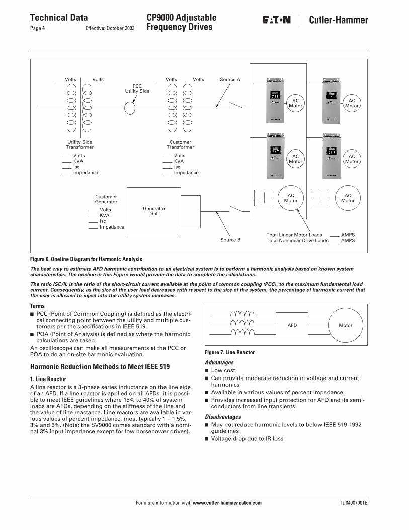
3. Clean Power Drives
When the total load is comprised of non-linear load such as drives and the ratio is Isc/I
L
, the greatest harmonic mitiga-tion is required. Under these conditions the currents drawn from the supply need to be sinusoidal and “Clean” such that system interference and additional losses are negligible. The Cutler-Hammer CP9000 Clean Power Drive uses a phase-shifting auto transformer with delta connected winding that carries only the ampere-turns caused by the difference in load currents. The basic configuration of the transformer is shown in
Figure 10
. In this type of configuration the total
KVA rating of the transformer magnetic system was only 48% that of the motor load. A traditional isolated trans-former system, with multipulse windings, would require the full KVA rating to be supported, which is more common in a MV step-down transformer.
The integrated 18-pulse clean power drive, with near sine wave input current and low harmonics will meet the require-ments of IEEE 519-1992 under all practical operating condi-tions. The comparisons with 6-pulse and 12-pulse systems are shown in
Figures 5
,
9
and
11
.
Figure 10. Basic 18-Pulse Rectifier with “Differential Delta” Transformer
Figure 11. 500 hp 480V Drive with 18-Pulse Rectifiers
Table 4. 500 hp 480V Drive with 18-Pulse Rectifiers
Advantages
■
Virtually guarantees compliance with IEEE 519-1992
■
Provides increased input protection for AFD and its semi-conductors from line transients
■
Up to 4 times the harmonic reduction of 12-pulse methods
■
Smaller transformer than isolation transformer used in 12-pulse converter
Disadvantages
■
Larger and heavier magnetics than some other methods
12
3
45
6
78
9
Output TransistorsIGBT Section
Dynamic BrakingTransistor
MainContactor
18-Pulse SCRBridge Rectifier
Converter Section
18-PulsePhase ShiftingTransformer
Inverter Section
(–) DC
(+) DC
Diode Rectifiers
BusCapacitors
3-PhaseAC Input
DifferentialDelta
Transformer1 12
3
4
5
6
5
63
2
77
1
9
23
8
8
ACMotor
18-Pulse Clean Power
Current Harmonics
I1 = 100% I11 = 0.24% I19 = 1.00%
I5 = 0.16% I13 = 0.10% I23 = 0.01%
I7 = 0.03% I17 = 0.86% I25 = 0.01%
Power = 428.8 kW
Hc = 24 Amps
1000
CurrentAmps
500
0
-500
-10000.100 0.10625 0.1125
Time in Seconds0.11875 0.125

TD04007001E For more information visit:
www.cutler-hammer.eaton.com
Technical Data
Effective: October 2003 Page
7
CP9000 Adjustable Frequency Drives
Technical Data and Specifications
Table 5. Drive Ratings
Table 6. CP9000 Enclosed Products Specifications
Table 6. CP9000 Enclosed Products Specifications (Continued)
�
Drive can be derated by one hp 480V AC size to become CT.
�
Increase drive by one frame size.Example: 60 hp VT = 50 hp CT
CP9000 Enclosed Products 480V25 hp VT – 800 hp VT
NEMA Type 1 25 – 700 hp CT25 – 800 hp VT
NEMA Type 1 with Gaskets and Filters 25 – 700 hp CT25 – 800 hp VT
NEMA Type 12 20 – 300 hp CT25 – 400 hp VT
Feature Description NEMA Type 1, NEMA Type 1with Gaskets and Filtersand NEMA Type 12
Primary Design Features
Reduced Voltage Starter (RVS)
IT.
Bypass45 – 66 Hz Input FrequencyOutput: AC Volts MaximumOutput Frequency Range: HzInitial Output Current (CT)
�
Overload: 1 Minute (CT/VT)
OptionalStandardInput Voltage Base.0 – 500250% for 2 seconds150%/110%
Enclosure Space HeaterOversize EnclosureOutput ContactorBypass Motor Starter/RVS(
IT.
)ListingsCE Mark
OptionalStandardOptionalOptionalUL—
Protection Features
Incoming Line FusesAC Input Circuit DisconnectLine ReactorsPhase Rotation InsensitiveInput Phase Loss Protection
StandardOptionalStandardStandardStandard
Input Overvoltage ProtectionLine Surge ProtectionOutput Short Circuit ProtectionOutput Ground Fault ProtectionOutput Phase Protection
StandardStandardStandardStandardStandard
Overtemperature ProtectionDC Overvoltage ProtectionDrive Overload ProtectionMotor Overload ProtectionProgrammer Software
StandardStandardStandardStandardOptional
Keypad LockoutFault Alarm OutputBuilt-In Diagnostics
StandardStandardStandard
Performance Features
Sensorless Vector ControlClosed Loop Vector ControlVolts/Hertz ControlIR and Slip CompensationElectronic Reversing
StandardOptionalStandardStandardStandard
Dynamic BrakingDC BrakingPI Setpoint ControllerCritical Speed LockoutCurrent (Torque) Limit
Optional
StandardProgrammableStandardStandard
Adjustable Acceleration/DecelerationLinear or S Curve Accel/DecelJog at Preset SpeedThread/Preset SpeedsAutomatic Restart
StandardStandardStandard7Selectable
Coasting Motor StartCoast or Ramp Stop SelectionElapsed Time MeterCarrier Frequency Adjustment
StandardStandardStandard1 – 16 kHz
Feature Description NEMA Type 1, NEMA Type 1with Gaskets and Filtersand NEMA Type 12
Input/Output Interface FeaturesSetup Adjustment Provisions:Remote Keypad/DisplayPersonal Computer
StandardStandard
Operator Control Provisions:Drive Mounted Keypad/DisplayRemote Keypad/DisplayConventional Control ElementsSerial Communications115V AC Control Circuit
StandardStandardStandardStandardStandard
Speed Setting Inputs:KeypadPotentiometer/Voltage Signal4 – 20 mA Isolated4 – 20 mA Differential3 – 15 psig
StandardStandardOptionalStandardOptional
Analog Outputs:Speed/FrequencyTorque/Load/CurrentMotor VoltageKilowatts0 – 10V DC Signals4 – 20 mA DC SignalsIsolated Signals
StandardProgrammableProgrammableProgrammableOptionalStandardOptional
Discrete Outputs:Fault AlarmDrive RunningDrive at Set SpeedOptional ParametersDry ContactsOpen Collector OutputsAdditional Discrete Outputs
StandardStandardProgrammable1411Optional
Communications:RS-232RS-422/485DeviceNet™Modbus RTUInterbus-SProfibus-DPLonworks®
StandardOptionalOptionalOptionalOptionalOptionalOptional
Standard Conditions for Application and Service Operating Ambient TemperatureStorage TemperatureHumidity (Maximum), Non-condensingAltitude (Maximum without Derate)Line Voltage VariationLine Frequency VariationEfficiencyPower Factor (Displacement)
0 – 40°C, 0 – 50°C � �-40 – 60°C95%3300 ft. (1000m)+10/-15%45 – 66 Hz>96%.96

For more information visit: www.cutler-hammer.eaton.com TD04007001E
Technical DataPage 8 Effective: October 2003
CP9000 Adjustable Frequency Drives
I/O Specifications
Table 7. I/O Specifications for the Control/Communication Options
A detailed listing of voltage, horse-power and enclosure configurations along with matching options is pro-vided in the Product Selection and Options sections. Stocking and manu-facturing location information is contained in Table 8.
Table 8. Vista Suffix
Table 9. Enclosed Products Program
Option Specification
Analog Voltage, Input 0 – ±10V, Ri ≥ 200 k�
Analog Current, Input 0 (4) – 20 mA, Ri = 250 �
Digital Input 24V: “0” ≤ 10V, “1” ≥ 18V, Ri > 5 k�
Aux. Voltage 24V (±20%), max. 50 mA
Reference Voltage 10V ±3%, max. 10 mA
Analog Current, OutputAnalog Voltage, Output
0 (4) – 20 mA, RL = 500 k�, resolution 10 bit, accuracy ≤ ±2%0 (2) – 10V, RL ≥ 1 k�, resolution 10 bit, accuracy ≤ ±2%
Relay Output Maximum switching voltage: 300V DC, 250V ACMaximum switching load: 8A/24V DC
.4A/300V DC2 kVA/250V AC
Maximum continuous load: 2A rms
Thermistor Input Rtrip = 4.7 k�
Encoder Input 24V: “0” ≤ 10V, “1” ≥18V, Ri = 2.2 k�5V: “0” ≤ 2V, “1” ≥ 3V, Ri = 330 �
QWT All VISTA registered CP9000 Enclosed Products, manufacturing location Watertown Plant
VWD Non-registered CP9000 Enclosed Products, manufacturing location Watertown Plant
CP9000 Enclosed Products 25 hp VT to 800 hp VT
Standard Enclosed Covers a wide range of the most commonly ordered options. Pre-engineering eliminates the lead time normally associated with customer specific options. Contact local sales office for lead time.
Modified Standard Enclosed
Applies to specific customer requirements that vary from the Standard Enclosed offering, such as the need for an additional indicating light or minor modifications to drawings. Contact local sales office for lead time.
Custom Engineered Applies to those applications with more unique or complex requirements. These are individually engineered to specific customer needs. Lead time is based on design complexity and drawing approval time. Contact local sales office for lead time.
Enclosure Definitions
NEMA Type 1Enclosures are intended for indoor use primarily to provide a degree of pro-tection against contact with enclosed equipment and provide a degree of protection against falling dirt in loca-tions where unusual service conditions do not exist. Top or side openings in the NEMA Type 1 enclosure allow for the free exchange of inside and out-side air while meeting the NEMA rod entry and rust resistance design tests.
NEMA Type 1 with Gaskets and FiltersEnclosures are intended for indoor use primarily to provide a degree of pro-tection against dust and falling dirt. Filtered air passed through gaskets and enclosure meets the NEMA rod entry and rust resistance design tests.
NEMA Type 12Enclosures are intended for indoor use primarily to provide a degree of pro-tection against dust, falling dirt and dripping noncorrosive liquids. To meet NEMA drip, dust and rust resistance tests, NEMA Type 12 enclosures have no openings to allow for the exchange of inside and outside air.

TD04007001E For more information visit: www.cutler-hammer.eaton.com
Technical DataEffective: October 2003 Page 9
CP9000 Adjustable Frequency Drives
Catalog Number Selection
Table 10. CP9000 Catalog Numbering System
C P 0 5 0 A G V 5 M 0 A 0 0 C X 3 X 7
Model CP9000
Horsepower Designations
025 = 25030 = 30040 = 40050 = 50060 = 60075 = 75100 = 100125 = 125150 = 150
200 = 200250 = 250300 = 300400 = 400500 = 500600 = 600700 = 700800 = 800
Series
A = A Series
Enclosure Rating
G = NEMA Type 1H = NEMA Type 1
w/Gaskets & FiltersD = NEMA Type 12
Torque
V = VariableC = Constant
Voltage
5 = 480V
Control Panel
M = SVMulti-line AlphanumericG = SVGraphic
Software(other than 0 denotes Special)
Dynamic BrakingChopper Circuit
A = No Chopper Circuit
Control/Communication Options
00 = No Modifications01 = 5 Digital Inputs, 2 Analog Inputs (1 Voltage, 1 Current), 3 Relay Outputs, Analog (Current) Output, Thermister Input, Encoder Input02 = 5 Digital Inputs, Relay Output, Thermistor Input03 = 5 Digital Inputs, 2 Analog (Voltage) Inputs, 3 Relay Outputs, Analog (Voltage) Output, Thermister Input, Encoder Input04 = 5 Digital Inputs, 3 Relay Outputs, Analog Output, Thermistor Input05 = Encoder Board06 = 6 Digital Input 120V AC Interface Card with 1 Analog Output. Provides isolation to existing 6 digital 24V DC inputs.30 = DeviceNet Network Communications 33 = InterBus S Network Communications31 = ProfiBus Network Communications 34 = LonWorks Network Communications32 = ModBus RTU Network Communications
Enclosed Options Type
C = Input Disconnect (HMCP)65 kAIC
D = Output ContactorI3 = Manual IOB Bypass
ControllerI4 = Manual HOA Bypass
ControllerL7 = MotoRx (300 – 600 Ft.)
1000 V/us DV/DT FilterL8 = MotoRx (100 – 300 Ft.)
1500 V/us DV/DT FilterL9 = EMI/RFI FilterL10 = Output FilterM = 3 – 15 psig FollowerM5 = 4 Channel – 120V AC
Control InterfaceM6 = Isolated Process FollowerM8 = Speed PotentiometerM9 = Speed Potentiometer
with HOAM15 = 8 Channel – 120V AC
Control InterfaceN1 = Custom Plastic NameplateN2 = Custom Metal NameplateR3 = Manual IOB Reduced
Voltage Starter BypassController
R4 = Manual HOA ReducedVoltage Starter BypassController
T1 = 115V Control Transformer— 105 VA
T2 = 115V Control Transformer— 300 VA
T3 = 115V Control Transformer— 550 VA
V2 = Space HeaterV5 = 10" ExpansionV6 = 20" ExpansionV7 = 26" ExpansionX5 = Bypass Pilot Lights for I3
and I4 OptionsX6 = Dual Overloads for BypassX7 = Bypass Test Switch for I3,
I4, R3 and R4Y4 = Single Overload RelayY5 = Dual Overload Relays
Input
OutputBypass
Bypass
Output
Output
InputOutputControlControl
ControlControlControl
Control
EnclosureEnclosureBypass
Bypass
Control
Control
Control
EnclosureEnclosureEnclosureEnclosureAddl. Bypass
Addl. BypassAddl. Bypass
OutputOutput
{ Build Suffix Alphabetically and Numerically

For more information visit: www.cutler-hammer.eaton.com TD04007001E
Technical DataPage 10 Effective: October 2003
CP9000 Adjustable Frequency Drives
Product Selection
Figure 12. NEMA 1 with Gasket and Filter, 25 – 200 hp (40 x 90 x 26)� Included with all CP9000 Drives.
When Ordering■ Select a Base Catalog Number that
meets the application requirements — nominal horsepower, voltage and enclosure rating (the enclosed drive’s continuous output amp rating should be equal to or greater than the motor’s full load amp rating). The base enclosed package includes a standard drive, door mounted SVMulti-line Control Panel and enclosure.
■ If SVGraphic Control Panel, Dynamic Brake Chopper, or Control/Communication option is desired, change the appropriate code in the Base Catalog Number.
■ Note: All of the programming is exactly the same as the standard SV9000 drive.
■ Select Enclosed Options. Add the codes as suffixes to the Base Catalog Number in alphabetical and numeric order.
SV9000Drive
Door MountedKeypad �
Input DisconnectHMCP
Option C
Input FusingOption C1 �
SCR BridgeRectifier �
Output ContactorOption D
Bypass ContactorOption I3, I4
IT. Reduced VoltageStarter BypassNot Shown R3, R4
BalancingReactor �
Bypass Pilot Lights& Selector SwitchesOption I3, I4Option R3, R4Option X5Option X7
18 Pulse AutoTransformer �
Transform �Cooling Fans

TD04007001E For more information visit: www.cutler-hammer.eaton.com
Technical DataEffective: October 2003 Page 11
CP9000 Adjustable Frequency Drives
480 AC Input — Constant /Variable Torque Base Drive
Table 11. 480V Drive and Enclosure �
� Enclosure dimensions listed on Pages 17 – 26.� Includes drive, SVMulti-line Control Panel and enclosure.
DriveFrameSize
CThp
ContinuousOutputAmps NEC @ 50°C
VThp
ContinuousOutputAmps NEC @ 40°C
NEMA Type 1 NEMA Type 1 with Gaskets and Filters
NEMA Type 12
Base CatalogNumber �
Base CatalogNumber �
Base CatalogNumber �
M5M6M6
202530
203240
253040
324052
CP9025AGV5M0A00CP9030AGV5M0A00CP9040AGV5M0A00
CP9025AHV5M0A00CP9030AHV5M0A00CP9040AHV5M0A00
CP9025ADV5M0A00CP9030ADV5M0A00CP9040ADV5M0A00
M6M6M6
405060
526577
506075
657796
CP9050AGV5M0A00CP9060AGV5M0A00CP9075AGV5M0A00
CP9050AHV5M0A00CP9060AHV5M0A00CP9075AHV5M0A00
CP9050ADV5M0A00CP9060ADV5M0A00CP9075ADV5M0A00
M7M7M7
75100125
96124156
100125150
124156180
CP9100AGV5M0A00CP9125AGV5M0A00CP9150AGV5M0A00
CP9100AHV5M0A00CP9125AHV5M0A00CP9150AHV5M0A00
CP9100ADV5M0A00CP9125ADV5M0A00CP9150ADV5M0A00
M8M8M9
150200250
180240302
200250300
240302361
CP9200AGV5M0A00CP9250AGV5M0A00CP9300AGV5M0A00
CP9200AHV5M0A00CP9250AHV5M0A00CP9300AHV5M0A00
CP9200ADV5M0A00CP9250ADV5M0A00CP9300ADV5M0A00
M9M10M10
300400500
361477590
400500600
477590720
CP9400AGV5M0A00CP9500AGV5M0A00CP9600AGV5M0A00
CP9400AHV5M0A00CP9500AHV5M0A00CP9600AHV5M0A00
CP9400ADV5M0A00CP9500ADV5M0A00CP9600ADV5M0A00
M11M12
600700
720840
700800
840960
CP9700AGV5M0A00CP9800AGV5M0A00
CP9700AHV5M0A00CP9800AHV5M0A00
CP9700ADV5M0A00CP9800ADV5M0A00

For more information visit: www.cutler-hammer.eaton.com TD04007001E
Technical DataPage 12 Effective: October 2003
CP9000 Adjustable Frequency Drives
Table 12. NEMA Type 1 & NEMA Type 1 w/ Gasket & Filters Enclosure Requirements
� Compact enclosure.� Contact sales office.
Table 13. NEMA Type 1 & NEMA Type 1 w/ Gasket & Filters Enclosure Approximate Dimensions in Inches
Table 14. NEMA Type 12 Enclosure Requirements
� Contact sales office.
Table 15. NEMA Type 12 Enclosure Approximate Dimensions in Inches
CThp
VThp
CB(C)
OutputContactor(D)
CB (C)with OC (D)(C with D)
CB (C) with Output Filter (L7) or (L8) or (L10)
CB (C) with OC (D) & Output Filter (L7) or (L8) or (L10)
EMI/RFI Filter Input Filter (L9)
Bypass(I3) or (I4)
Bypass(R3) or (R4)
Bypass(I3) or (I4) with (L7), (L8) or (L10)
Bypass (R3) or (R4) with (L7), (L8) or (L10)
20, 25, 3040, 50, 6075
25, 30, 4050, 60, 75100
BBB
BBB
BBB
BBB
BBB
�
�
�
B B B
B BB
B B B
B B B
100125175
125150200
BBB �
BBB �
BBB �
BBB �
BBC
�
�
�
B CC
BBC
B B C
B-3PB-3PC
175, 200250300
200, 250300400
C C C
C C C
C C C
C C C
C C C
�
�
�
C C C
C C-3PC-3P
CC using L7, or L8C using L7, or L8
C C-3PC-3P
400, 500
600700
500, 600
700800
D
E�
D
E�
D
E�
D
E�
D without L10E�
�
�
�
D-3P
——
D-3P
——
D-3P
�
�
D-3P without L10�
�
Enclosure Page Drive Transformer Expansion Enclosure Total Enclosure
BB-3PC
171920
90 x 40 x 2690 x 40 x 2690 x 40 x 26
IncludedIncluded90 x 36 x 26
N/A90 x 26 x 26N/A
90 x 40 x 2690 x 66 x 2690 x 76 x 26
C-3PDD-3PE
22232425, 26
90 x 40 x 2690 x 60 x 2690 x 60 x 26Qty 2 90 x 40 x 26
90 x 36 x 2690 x 41 x 2690 x 41 x 26Qty 2 90 x 36 x 26
90 x 26 x 26N/A90 x 26 x 2690 x 26 x 26
90 x 102 x 2690 x 101 x 2690 x 127 x 2690 x 178 x 26
CThp
VThp
CB(C)
OutputContactor(D)
CB (C)with OC (D)(C with D)
CB (C) with Output Filter (L7) or (L8) or (L10)
CB (C) with OC (D) & Output Filter (L7) or (L8) or (L10)
EMI/RFI Filter Input Filter (L9)
Bypass(I3) or (I4)
Bypass(R3) or (R4)
Bypass(I3) or (I4) with (L7), (L8) or (L10)
Bypass (R3) or (R4) with (L7), (L8) or (L10)
20, 25, 3040, 50, 6075
25, 30, 4050, 60, 75100
BBB
BBB
BBB
BBB
BBB
�
�
�
B B B
B BB
B B B
B B B
100, 125150, 200250, 300
125,150200, 250300, 400
CN12CN12 —
CN12CN12 —
CN12CN12 —
CN12CN12�
CN12CN12�
�
�
�
CN12CN12 —
CN12CN12 —
CN12CN12�
CN12CN12�
Enclosure Page Drive Transformer Expansion Enclosure Total Enclosure
BCN12
1721
90 x 40 x 2690 x 40 x 26
Included90 x 36 x 26
N/A90 x 26 x 26
90 x 40 x 2690 x 102 x 26

TD04007001E For more information visit: www.cutler-hammer.eaton.com
Technical DataEffective: October 2003 Page 13
CP9000 Adjustable Frequency Drives
Options
Control/Communication Options
Table 16. Control/Communication Products Options NEMA Type 1, NEMA Type 1 with Gaskets and Filter, NEMA Type 12 �
� Provisions allow for only one control/communication option at a time.� Requires specific application software and optional motor mounted encoder, contact sales office for details.
Other OptionsTable 17. Miscellaneous Options
Description Factory Installed Field Installed
Option Designator Catalog Number
Expander I/O Cards — The Expander I/O Cards provide isolated I/O in addition to the standard I/O included with the CP9000.5 Digital Inputs, 2 Analog Inputs (1 voltage, 1 current), 3 Relay Outputs, Analog (current) Output, Thermistor Input, Encoder Input �
01 SV9IOC100
5 Digital Inputs, Relay Output, Thermistor Input 02 SV9IOC101
5 Digital Inputs, 2 Analog (voltage) Inputs, 3 Relay Outputs, Analog (voltage) Output, Ther-mistor Input, Encoder Input �
03 SV9IOC102
5 Digital Inputs, 3 Relay Outputs, Analog Output, Thermistor Input 04 SV9IOC103
6 Digital Input 120V AC Interface Card with 1 Analog Output. Provides isolation to existing 6 digital 24V DC inputs.
06 SV9IOC105
Encoder Board — Provides closed loop speed regulation. � 05 SV9IOC104
Network CardsDeviceNet Network Communications — The DeviceNet Network Card is used for connecting the CP9000 on a DeviceNet Network. It includes a 5.08 mm pluggable connector. Transfer method is via CAN using a 2-wire twisted shielded cable with 2-wire bus power cable and drain. The baud rates used for communication include 125K baud, 250K baud and 500K baud.
30 SV9NCDN
Profibus Network Communications — The Profibus Network Card is used for connecting the CP9000 as a slave on a Profibus-DP network. The interface is connected by a 9-pin DSUB connector (female). The baud rates range from 9.6K baud to 12M baud, and the addresses range from 1 to 127. The Profibus card additionally includes the following control I/O — 4 digital inputs, 4 digital outputs, 1 relay output, thermistor input, and an encoder input.
31 SV9NCPB
ModBus RTU Network Communications — The Modbus Network Card is used for connecting the CP9000 as a slave on a Modbus network. The interface is connected by a 9-pin DSUB connector (female) and the baud rate ranges from 300 to 19200 baud. Other communication parameters include an address range from 1 to 247; a parity of None, Odd or Even; and the stop bit is 1. The ModBus card additionally includes the following control I/O — 4 digital inputs, 4 digital outputs, a thermistor input and an encoder input.
32 SV9NCMB
InterBus-S Network Communications — The InterBus-S Network Card is used for connecting the CP9000 as a remote bus device within the InterBus-S system. The interface is connected into the remote bus using a 9-pin DSUB connector. The InterBus card additionally includes the following control I/O — 4 digital inputs, 4 digital outputs, 1 relay output, a thermistor input and an encoder input.
33 SV9NCIB
LonWorks Network Communications — The LonWorks Network Card is used for connecting the CP9000 on a LonWorks network. This interface uses Standard Network Variable Types (SNVT) as data types. The channel connection is achieved using a FTT-10A Free Topology transceiver via a single twisted transfer cable. The communication speed with LonWorks is 78 kBits/s. The LonWorks card additionally includes the following control I/O — 4 digital inputs, 4 digital outputs, 1 relay output, a thermistor input and an encoder input.
34 SV9NCLWCN
DeviceNet Network Close Loop Communications — The DeviceNet Network Card is used for connecting the CP9000 on a DeviceNet Network. It includes a 5.08 mm plug Cable connector. Transfer method is via CAN using a 2-wire twisted shielded cable with 2-wire bus power cable and drain. The baud rates used for communication include 125K baud, 250K baud and 500K baud. The device incorporates an encoder input.
35 SV9NCDNCL
Description Catalog Number
SVDrive — A PC-based tool for control and monitoring of the CP9000. Features include: loading parameters that can be saved to a file or printed, setting references, starting and stopping the motor, monitoring signals in graphical or text form, and real-time display. To avoid damage to the drive or computer, SVDrivecable must be used.
SVDRIVE
SVDrivecable — 6 ft. RS-232 cable (22 gauge) with a 7-pin connector on each end. Should be used in conjunction with the SVDrive option to avoid damage to the CP9000 or computer. The same cable can be used for downloading specialized applications to the drive.
SVDRIVECABLE
RWT — The Reflective Wave Trap (RWT) decreases the reflective wave voltage spikes at the motor terminals. The RWT is recommended for cable lengths exceeding 100 ft. This option must be installed within 25 ft. of the motor terminals, and operates with a carrier frequency of up to 12 kHz. (See Publication No. B.37F.01.SE for more information.)
RWTCHR1RWTCHR4

For more information visit: www.cutler-hammer.eaton.com TD04007001E
Technical DataPage 14 Effective: October 2003
CP9000 Adjustable Frequency Drives
Control Panel OptionsTable 18. Control Panel Factory Options — Enclosed Products
Enclosed Options
Table 19. Available Options — Build Alphabetically and Numerically
Note: For complete descriptions, see Pages 15 – 16.
Table 20. Engineered Enclosed Options
Note: Engineered options include mounting and wiring.
Description Factory Installed
Field Installed on Enclosure Door
NEMA Type 1, NEMA Type 1 w/Gaskets & Filter
NEMA Type 12
OptionDesignator
Catalog Number Catalog Number
SVMulti-line Control Panel — This option is standard on all drives and consists of a 4-line, 16 character/line, backlit alphanumeric LCD display with five indicators for the RUN status and two indicators for the control source. The eight pushbuttons on the panel are used for panel programming and monitoring of all CP9000 parameters. The panel is detachable and isolated from the input line potential.
M SV9REMMLPNL SV9REMMLPNL
SVGraphic Control Panel — Includes eight lines of text or a 64 x 128 pixel graphical display of key waveforms, or a combination of both text and graphs. It provides:■ 3 monitored parameters at the same time in text or graphical trend display■ one monitored parameter can be shown in increased text size with a graph bar■ the selected parameter value is shown on a graph bar■ the parameters of the drive can be uploaded to the panel and then downloaded to
another drive
G SV9GRPNL SV9GRPNL
Option Description Option Type
CDI3
Input Disconnect (HMCP) 65 kAICOutput ContactorManual IOB Bypass Controller
InputOutputBypass
I4L7L8
Manual HOA Bypass ControllerMotoRx (300 – 600 Ft.) 1000 V/us DV/DT FilterMotoRx (100 – 300 Ft.) 1500 V/us DV/DT Filter
BypassOutputOutput
L9L10M
EMI/RFI FilterOutput Filter3 – 15 psig Follower
InputOutputControl
M5M6M8
4 Channel — 120V AC Control InterfaceIsolated Process FollowerDoor-Mounted Speed Potentiometer
ControlControlControl
M9M15N1
Door-Mounted Speed Potentiometer with HOA8 Channel — 120V AC Control InterfaceCustom Plastic Nameplate
ControlControlEnclosure
N2R3R4
Custom Metal NameplateIOB Bypass Controller with RVSHOA Bypass Controller with RVS
EnclosureBypassBypass
T1T2T3
115 Volt Control Transformer — 105 VA115 Volt Control Transformer — 300 VA115 Volt Control Transformer — 550 VA
ControlControlControl
V1V2V4
Floor Stand 22"
Space HeaterFloor Stand 12"
EnclosureEnclosureEnclosure
V5V6V7
10" Expansion20" Expansion26" Expansion
EnclosureEnclosureEnclosure
X5X6X7
Bypass Pilot Lights for I3, I4 OptionsDual Overloads for BypassBypass Test Switch for I3, I4, R3, R4
Addl. BypassAddl. BypassAddl. Bypass
Y4Y5
Single Overload RelayDual Overload Relays
OutputOutput
Option Description
A Amp Meter (Digital) (Drive 4 – 20 mA)
CR 120V Control Relay
E Elapse Time Meter
E2 ESTOP (22 mm)
E3 ESTOP (30 mm)
K2 Key Lockable Selector Switch 2-Position (22 mm)
K3 Key Lockable Selector Switch 3-Position (22 mm)
K4 Key Lockable Selector Switch 4-Position (22 mm)
MP MP3000 Motor Protection, 5 Amp, URTD, IPONI, F.O. Link with CT and PT
P2 Pushbuttons — 22m
P3 Pushbuttons — 30m
PT Push to Test Pilot Lights (30 mm)
Q Frequency Meter
RT Durant RTD Temperature Module with Alarm Trip Module and LED Readout
S2 2-Position Selector Switch (22 mm)
S3 3-Position Selector Switch (22 mm)
S4 4-Position Selector Switch (22 mm)
SP 10 Turn Speed Pot
T20 Customer Terminal Block 20 Terminals
TD Timing Relay Type M Relay with Timing Attachment
V Volt Meter (digital) (Drive 4 – 20 mA)
W Witness Test/Day
TD04007001E For more information visit: www.cutler-hammer.eaton.com
Technical DataEffective: October 2003 Page 15
CP9000 Adjustable Frequency Drives
Enclosed Options Descriptions
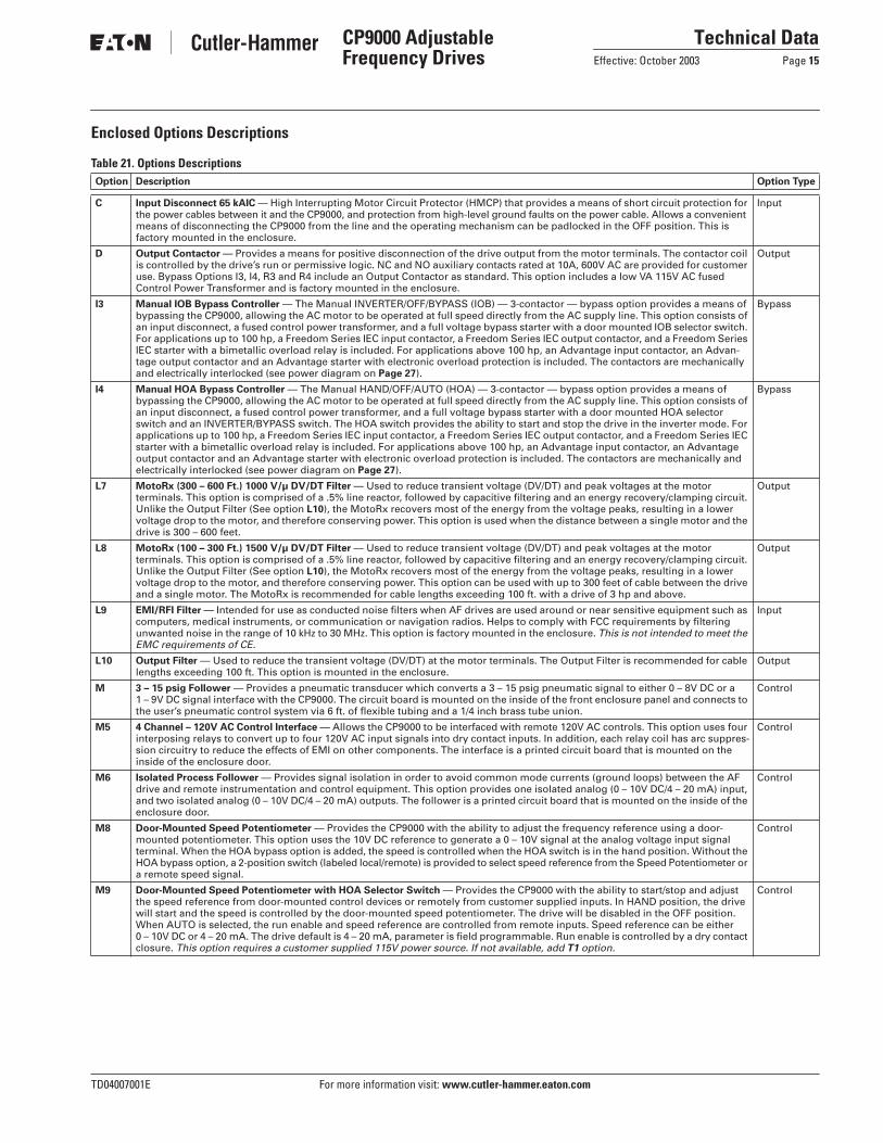
Table 21. Options DescriptionsOption Description Option Type
C Input Disconnect 65 kAIC — High Interrupting Motor Circuit Protector (HMCP) that provides a means of short circuit protection for the power cables between it and the CP9000, and protection from high-level ground faults on the power cable. Allows a convenient means of disconnecting the CP9000 from the line and the operating mechanism can be padlocked in the OFF position. This is factory mounted in the enclosure.
Input
D Output Contactor — Provides a means for positive disconnection of the drive output from the motor terminals. The contactor coil is controlled by the drive’s run or permissive logic. NC and NO auxiliary contacts rated at 10A, 600V AC are provided for customer use. Bypass Options I3, I4, R3 and R4 include an Output Contactor as standard. This option includes a low VA 115V AC fused Control Power Transformer and is factory mounted in the enclosure.
Output
I3 Manual IOB Bypass Controller — The Manual INVERTER/OFF/BYPASS (IOB) — 3-contactor — bypass option provides a means of bypassing the CP9000, allowing the AC motor to be operated at full speed directly from the AC supply line. This option consists of an input disconnect, a fused control power transformer, and a full voltage bypass starter with a door mounted IOB selector switch. For applications up to 100 hp, a Freedom Series IEC input contactor, a Freedom Series IEC output contactor, and a Freedom Series IEC starter with a bimetallic overload relay is included. For applications above 100 hp, an Advantage input contactor, an Advan-tage output contactor and an Advantage starter with electronic overload protection is included. The contactors are mechanically and electrically interlocked (see power diagram on Page 27).
Bypass
I4 Manual HOA Bypass Controller — The Manual HAND/OFF/AUTO (HOA) — 3-contactor — bypass option provides a means of bypassing the CP9000, allowing the AC motor to be operated at full speed directly from the AC supply line. This option consists of an input disconnect, a fused control power transformer, and a full voltage bypass starter with a door mounted HOA selector switch and an INVERTER/BYPASS switch. The HOA switch provides the ability to start and stop the drive in the inverter mode. For applications up to 100 hp, a Freedom Series IEC input contactor, a Freedom Series IEC output contactor, and a Freedom Series IEC starter with a bimetallic overload relay is included. For applications above 100 hp, an Advantage input contactor, an Advantage output contactor and an Advantage starter with electronic overload protection is included. The contactors are mechanically and electrically interlocked (see power diagram on Page 27).
Bypass
L7 MotoRx (300 – 600 Ft.) 1000 V/µ DV/DT Filter — Used to reduce transient voltage (DV/DT) and peak voltages at the motor terminals. This option is comprised of a .5% line reactor, followed by capacitive filtering and an energy recovery/clamping circuit. Unlike the Output Filter (See option L10), the MotoRx recovers most of the energy from the voltage peaks, resulting in a lower voltage drop to the motor, and therefore conserving power. This option is used when the distance between a single motor and the drive is 300 – 600 feet.
Output
L8 MotoRx (100 – 300 Ft.) 1500 V/µ DV/DT Filter — Used to reduce transient voltage (DV/DT) and peak voltages at the motor terminals. This option is comprised of a .5% line reactor, followed by capacitive filtering and an energy recovery/clamping circuit. Unlike the Output Filter (See option L10), the MotoRx recovers most of the energy from the voltage peaks, resulting in a lower voltage drop to the motor, and therefore conserving power. This option can be used with up to 300 feet of cable between the drive and a single motor. The MotoRx is recommended for cable lengths exceeding 100 ft. with a drive of 3 hp and above.
Output
L9 EMI/RFI Filter — Intended for use as conducted noise filters when AF drives are used around or near sensitive equipment such as computers, medical instruments, or communication or navigation radios. Helps to comply with FCC requirements by filtering unwanted noise in the range of 10 kHz to 30 MHz. This option is factory mounted in the enclosure. This is not intended to meet the EMC requirements of CE.
Input
L10 Output Filter — Used to reduce the transient voltage (DV/DT) at the motor terminals. The Output Filter is recommended for cable lengths exceeding 100 ft. This option is mounted in the enclosure.
Output
M 3 – 15 psig Follower — Provides a pneumatic transducer which converts a 3 – 15 psig pneumatic signal to either 0 – 8V DC or a 1 – 9V DC signal interface with the CP9000. The circuit board is mounted on the inside of the front enclosure panel and connects to the user’s pneumatic control system via 6 ft. of flexible tubing and a 1/4 inch brass tube union.
Control
M5 4 Channel – 120V AC Control Interface — Allows the CP9000 to be interfaced with remote 120V AC controls. This option uses four interposing relays to convert up to four 120V AC input signals into dry contact inputs. In addition, each relay coil has arc suppres-sion circuitry to reduce the effects of EMI on other components. The interface is a printed circuit board that is mounted on the inside of the enclosure door.
Control
M6 Isolated Process Follower — Provides signal isolation in order to avoid common mode currents (ground loops) between the AF drive and remote instrumentation and control equipment. This option provides one isolated analog (0 – 10V DC/4 – 20 mA) input, and two isolated analog (0 – 10V DC/4 – 20 mA) outputs. The follower is a printed circuit board that is mounted on the inside of the enclosure door.
Control
M8 Door-Mounted Speed Potentiometer — Provides the CP9000 with the ability to adjust the frequency reference using a door-mounted potentiometer. This option uses the 10V DC reference to generate a 0 – 10V signal at the analog voltage input signal terminal. When the HOA bypass option is added, the speed is controlled when the HOA switch is in the hand position. Without the HOA bypass option, a 2-position switch (labeled local/remote) is provided to select speed reference from the Speed Potentiometer or a remote speed signal.
Control
M9 Door-Mounted Speed Potentiometer with HOA Selector Switch — Provides the CP9000 with the ability to start/stop and adjust the speed reference from door-mounted control devices or remotely from customer supplied inputs. In HAND position, the drive will start and the speed is controlled by the door-mounted speed potentiometer. The drive will be disabled in the OFF position. When AUTO is selected, the run enable and speed reference are controlled from remote inputs. Speed reference can be either 0 – 10V DC or 4 – 20 mA. The drive default is 4 – 20 mA, parameter is field programmable. Run enable is controlled by a dry contact closure. This option requires a customer supplied 115V power source. If not available, add T1 option.
Control

For more information visit: www.cutler-hammer.eaton.com TD04007001E
Technical DataPage 16 Effective: October 2003
CP9000 Adjustable Frequency Drives
Table 21. Options Descriptions (Continued)Option Description Option Type
M15 8 Channel – 120V AC Control Interface — Allows the CP9000 to be interfaced with remote 115V AC controls. This option uses eight interposing relays to convert up to eight 120V AC input signals into dry contact inputs. In addition, each relay coil has arc suppression circuitry to reduce the effects of EMI on other components. The interface is a printed circuit board that is mounted on the inside of the enclosure door.
Control
N1 Custom Plastic Nameplate — A 3 x 5 inch laminated plastic sheet, which can include up to two lines of 15 characters each. Enclosure
N2 Custom Metal Nameplate — A 3 x 5 inch stainless steel sheet, which can include up to two lines of 15 characters each. Enclosure
R3 Manual IOB Bypass Controller — The Manual INVERTER/OFF/BYPASS (IOB) — 3-contactor — bypass option provides a means of bypassing the CP9000, allowing the AC motor to be operated at full speed directly from the AC supply line. This option consists of an input disconnect, a fused control power transformer, and a full voltage bypass starter and (IT.) reduced voltage starter with a door mounted IOB selector switch. For applications up to 100 hp, a Freedom Series IEC input contactor, a Freedom Series IEC out-put contactor, and a Freedom Series IEC starter with a bimetallic overload relay is included. For applications above 100 hp, an Advantage input contactor, an Advantage output contactor and an Advantage starter with electronic overload protection is included. The contactors are mechanically and electrically interlocked (see power diagram on Page 27).
Bypass
R4 Manual HOA Bypass Controller — The Manual HAND/OFF/AUTO (HOA) — 3-contactor — bypass option provides a means of bypassing the CP9000, allowing the AC motor to be operated at full speed directly from the AC supply line. This option consists of an input disconnect, a fused control power transformer, and a full voltage bypass starter and (IT.) reduced voltage starter with a door mounted HOA selector switch and an INVERTER/BYPASS switch. The HOA switch provides the ability to start and stop the drive in the inverter mode. For applications up to 100 hp, a Freedom Series IEC input contactor, a Freedom Series IEC output con-tactor, and a Freedom Series IEC starter with a bimetallic overload relay is included. For applications above 100 hp, an Advantage input contactor, an Advantage output contactor and an Advantage starter with electronic overload protection is included. The con-tactors are mechanically and electrically interlocked (see power diagram on Page 27).
Bypass
T1 115V Control Transformer – 105 VA — Provides a fused control power transformer with additional 105 VA at 115V for customer use. Control
T2 115V Control Transformer – 300 VA — Provides a fused control power transformer with additional 300 VA at 115V for customer use. Control
T3 115V Control Transformer – 550 VA — Provides a fused control power transformer with additional 550 VA at 115V for customer use. Control
V2 Space Heater — Prevents condensation from forming in the enclosure when the drive is inactive or in storage. Includes a thermostat for variable temperature control. A 200W heater is installed in enclosures 0 and 1, and a 400W heater is installed in enclosures 2 – 6. Requires a customer supplied 115V remote supply source.
Enclosure
V5 10" Expansion — The extension allows for bottom cable entry and additional space for customer mounted components.
NOTE: Enclosure expansion rated NEMA Type 1 only.
Enclosure
V6 20" Expansion — The extension allows for bottom cable entry and additional space for customer mounted components.
NOTE: Enclosure expansion rated NEMA Type 1 only.
Enclosure
V7 26" Expansion — The extension allows for bottom cable entry and additional space for customer mounted components.The enclosure also has a subpanel with C3 flange.
NOTE: Enclosure expansion rated NEMA Type 1 only.
Enclosure
X5 Bypass Pilot Lights for I3, I4 Bypass Options — A green light indicates when the motor is running in inverter mode and an amber light indicates when the motor is running in bypass mode. The lights are mounted on the enclosure door, above the switches.
Addl. Bypass
X6 Dual Overloads for Bypass — This option is recommended when a single drive is operating 2 motors in the bypass mode and overload current protection is needed for each of the motors. The standard configuration includes two bimetallic overload relays, each sized to protect a motor with 50% of the drive hp rating. For example, a 100 hp drive would include two overload relays sized to protect two 50 hp motors. The relays are mounted within the enclosure, and are manually resettable.
Addl. Bypass
X7 Bypass Test Switch for I3, R3, I4 and R4 — Allows the user to energize the AF drive for testing while operating the motor on the bypass controller. The Test Switch is mounted on the inside of the enclosure door.
Addl. Bypass
Y4 Single Overload Relay — Uses a bimetallic overload relay to provide additional overload current protection to the motor on configurations without bypass options. It is included with the Bypass Configurations for overload current protection in the bypass mode. The Overload Relay is mounted within the enclosure, and is manually resettable.
Output
Y5 Dual Overload Relays — This option is recommended when a single drive is operating 2 motors and overload current protection is needed for each of the motors. The standard configuration includes two bimetallic overload relays, each sized to protect a motor with 50% of the drive hp rating. For example, a 100 hp drive would include two overload relays sized to protect two 50 hp motors. The relays are mounted within the enclosure, and are manually resettable.
Output

TD04007001E For more information visit: www.cutler-hammer.eaton.com
Technical DataEffective: October 2003 Page 17
CP9000 Adjustable Frequency Drives
Dimensions
Figure 13. 25 – 200 hp, Size B Approximate Dimensions in Inches (mm)
90.00(2286.0)
84.37(2142.9)
93.96(2386.5)
4.00 (101.6) MinimumFree Air Space Required
Lifting Eyes(2 Places)
OptionalFilter
25.00(634.9)
40.00(1016.0)
93.96(2386.5)
20.20(513.2)
36.25(920.8) Hinged Side
DoorClearance
at 90°
10.00(254.0)
9.55(242.5)
17.55(445.8)
6.33(160.9)
4.00 (101.6) MinimumFree Air Space Required
Lifting Eyes(2 Places)
OptionalFilter
.56 (14.2) Dia.Mounting Holes
(3 Places)
ForCable Entry
ExhaustAir
Cover Plate(2 Places)
40.00(1016.0)
4.00(101.6)
Finish: Enclosure – ANSI 61 Light GrayWeight: Approximately 1000 lbs. (454 kg)
34.62(879.4)
3.08(78.2)12.30
(312.4)
20.50(520.6)26.29
(667.9)
Top View
Bottom ViewNo Bottom Wire Entry and Exit
For Reference Only, Dimensions Subject
to Change.
Front View NEMA 12 Size B
Front View NEMA 1 &
NEMA 1 with Gaskets & Filters Size B
Side View

For more information visit: www.cutler-hammer.eaton.com TD04007001E
Technical DataPage 18 Effective: October 2003
CP9000 Adjustable Frequency Drives
Figure 14. 25 – 200 hp, Size B-1P Approximate Dimensions in Inches (mm)
90.00(2286.0)
84.37(2142.9)
93.96(2386.5)
4.00 (101.6) MinimumFree Air Space Required
Lifting Eyes(2 Places)
Lifting Eyes(2 Places)
25.00(634.9)
40.00 (1016.0) 10.00(254.0)
50.00 (1270.0)
10.00(254.0)40.00 (1016.0)
50.00 (1270.0)
93.96(2386.5)
20.20(513.2)
36.25(920.8) Hinged Side
DoorClearance
at 90°
17.11(434.5)
17.55(445.8)
6.33(160.9)
18.36(466.3)
1.25(31.8)
4.00 (101.6) MinimumFree Air Space Required
.56 (14.2) Dia.Mounting Holes
(3 Places)
ForCable Entry
ForCable Entry
ExhaustAir
Cover Plate(2 Places)
4.00(101.6)
Finish: Enclosure – ANSI 61 Light GrayWeight: Approximatley 1100 lbs. (500 kg)
34.62(879.4)
8.00(203.3)
1.00(25.4)
1.30(33.0)
8.00(203.3)
1.00(25.4)
20.50(520.6)26.29
(667.9)
Top View
Bottom View
For Reference Only, Dimensions Subject
to Change.
Front View NEMA 12 Size B-1PTop and Bottom Cable Entry
Front View NEMA 1 &NEMA 1 with Gaskets & Filters Size B-1P
Top and Bottom Cable Entry
Side View
V2 10" Expansion
V2 10" Expansion

TD04007001E For more information visit: www.cutler-hammer.eaton.com
Technical DataEffective: October 2003 Page 19
CP9000 Adjustable Frequency Drives
Figure 15. 100 – 200 hp, Size B-3P Approximate Dimensions in Inches (mm)
.56 (14.2) Dia. Mounting Holes(7 Places)
40.00 (1016.0)
Bottom View
Front View NEMA 1 & NEMA 1 with Gaskets & Filters Size B-3P
17.55 (445.8)
6.33 (160.9)
20.20 (513.2)
90.00 (2286.0)
93.51 (2375.2)
34.62 (879.4) 21.87 (555.4)2.00 (50.8)4.00 (101.6)
This Area May Be Usedfor Bottom Access
Side View
26.00 (660.4)
25.00 (635.0)26.14 (664.0)
Construction: NEMA Type 1 OversizeFinish: Enclosure – ANSI 61 Gray Weight: VFD Enclosure 1000 lbs. (454 kg) Bypass Enclosure 700 lbs. (318 kg)
INVEnclosure
BypassEnclosure(ShippedAttached)
Exhaust Air Access in Top
Exhaust Air
10.00(254.0)
14.30 (363.2)
4.20 (106.7)
6.13 (155.7)
11.50 (292.1)
Access Panel
35.75(908.1)
Top View
For Reference Only, Dimensions Subject
to Change.
12.30(312.4)
15.00(381.0)
7.60(193.0)
15.75(400.1)
14.30 (363.2)
6.13 (155.7)
11.50 (292.1)
Access Panel
7.46(189.5)
4.00 (101.6) MinimumFree Air Space Required
10.03(254.7)
3.18(80.8)
21.75(552.4)
5.45(138.5)
11.09(281.6)

For more information visit: www.cutler-hammer.eaton.com TD04007001E
Technical DataPage 20 Effective: October 2003
CP9000 Adjustable Frequency Drives
Figure 16. 200 – 400 hp, Size C Approximate Dimensions in Inches (mm)
4.00 (101.6) MinimumFree Air Space Required
Clean PowerTransformer Enclosure(Shipped Not Attached)
VFDEnclosure
90.00(2286.0)
93.50(2374.9)
.56 (14.2) Dia.Mounting Holes
(4 Places)
NotFiltered
Exhaust Air Access in Top
10.00(254.0)
10.03(254.7)
12.30(312.4)
3.14 (79.8)
35.75(908.1)
CleanPower
Transformer
Weight: M8 VFD Enclosure 1000 lbs. (454 kg) M8 Transformer Enclosure 1600 lbs. (726 kg) M9 VFD Enclosure 1100 lbs. (500 kg) M9 Transformer Enclosure 2800 lbs. (1270 kg)
36.00 (914.4)
Bottom ViewNo Bottom Access
Top ViewTop Entry and Exit for Cabling
For Reference Only, Dimensions Subject
to Change.
Front View NEMA 1 & NEMA 1 with Gaskets & Filters Size C
“A”
8.00(203.2)
15.85(402.6)
36.01 (914.7)
1.90(48.1)
40.00 (1016.0)“A”
Section “A-A”Floor Access & Mounting Dimensions
Side View
26.14 (664.0)
14.30 (363.2)
4.20 (106.7)
6.13 (155.7)
11.50 (292.1)
Access Panel
14.30 (363.2)
6.13 (155.7)
11.50 (292.1)
Access Panel

TD04007001E For more information visit: www.cutler-hammer.eaton.com
Technical DataEffective: October 2003 Page 21
CP9000 Adjustable Frequency Drives
Figure 17. 200 – 400 hp, CN12 Approximate Dimensions in Inches (mm)
4.00 (101.6) MinimumFree Air Space Required
Clean PowerTransformer Enclosure(Shipped Not Attached)
VFD Enclosure
AccessPanel
.56 (14.2) Dia.Mounting Holes
(8 Places)
This Area May Be Usedfor Bottom Access
AccessPanel
V7 EnclosureSCR Bridge
Rectifier Section(Shipped Attached)
Clean PowerTransformer
EnclosureVFD & SCR EnclosuresAre Shipped Attached. Weight: M8 VFD Enclosure 1000 lbs. (454 kg) M8 Transformer Enclosure 1600 lbs. (726 kg) M8 SCR Enclosure 1000 lbs. (454 kg) M9 VFD Enclosure 1100 lbs. (500 kg) M9 Transformer Enclosure 2800 lbs. (1270 kg) M9 SCR Enclosure 1000 lbs. (454 kg)
26.00 (660.4)36.00 (914.4)
For Reference Only, Dimensions Subject
to Change.
Front View NEMA 12 Size CN12
“A”
8.00(203.2)
15.87(403.2)
15.75(400.1)
7.60(193.0)
36.01 (914.7)1.90 (48.1)1.90 (48.4)21.87 (555.4)
40.00 (1016.0)
“A”
Section “A-A”Floor Access & Mounting Dimensions
Exhaust Air
Access in TopAccess in Top
10.00(254.0)
10.03(254.7)
20.00(508.0)
26.00(660.4) 7.46
(189.5)
11.09(281.6)
12.30(312.4)
35.75(908.1)
21.75(552.4)
Top ViewTop Entry and Exit for Cabling
15.00(381.0)
5.55(140.9)
Bottom ViewNo Bottom Access
90.00 (2286.0)
93.50(2374.9)
Side View
26.14 (664.0)
14.30 (363.2)
4.20 (106.7)
6.13 (155.7)
11.50 (292.1)
14.30 (363.2)
6.13 (155.7)
11.50 (292.1)

For more information visit: www.cutler-hammer.eaton.com TD04007001E
Technical DataPage 22 Effective: October 2003
CP9000 Adjustable Frequency Drives
Figure 18. 400 hp, C-3P Approximate Dimensions in Inches (mm)
4.00 (101.6) MinimumFree Air Space Required
Clean PowerTransformer Enclosure(Shipped Not Attached)
90.00(2286.0)
93.50(2374.9)
.56 (14.2) Dia.Mounting Holes
(8 Places)
This Area MayBe Used for
Bottom Access
FlangedDisconnect
Supplied withCircuit BreakerWhen Specified
Clean PowerTransformer Enclosure
VFD & Bypass Enclosures AreShipped Attached. Construction: NEMA Type 1 OversizeFinish: Enclosure – ANSI 61 Gray Weight: M8 VFD Enclosure 1000 lbs. (454 kg) M8 Transformer Enclosure 1600 lbs. (726 kg) M8 Bypass Enclosure 1000 lbs. (454 kg) M9 VFD Enclosure 1100 lbs. (500 kg) M9 Transformer Enclosure 2800 lbs. (1270 kg) M9 Bypass Enclosure 1000 lbs. (454 kg)
26.00 (660.4)36.00 (914.4)
For Reference Only, Dimensions Subject
to Change.
“A”
8.00(203.2)
15.85(402.6)
15.75(400.1)
7.60(193.0)
36.01 (914.7)1.90 (48.4)
1.90 (48.1) 21.87 (555.4)
26.14 (664.0)
Side View
40.00 (1016.0)
“A”
Section “A-A”Floor Access & Mounting Dimensions
10.00(254.0)
10.03(254.7)
7.46(189.5)
Top ViewTop Access Only
15.00(381.0)
5.45(138.5)
11.09(281.6)
Bottom ViewNo Bottom Access
VFD Enclosure
V7 EnclosureBypass Enclosure
(Shipped Attached) 14.30 (363.2)
4.20 (106.7)
6.13 (155.7)
11.50 (292.1)
6.13 (155.7)
Access Panel
Access Panel
Exhaust Air Access in Top
35.75(908.1)
12.30(312.4)
3.18 (80.8)
Front View NEMA 1 & NEMA 1 with Gasket & Filter Size C-3P
21.75(552.4)

TD04007001E For more information visit: www.cutler-hammer.eaton.com
Technical DataEffective: October 2003 Page 23
CP9000 Adjustable Frequency Drives
Figure 19. 500 – 600 hp, Size D Approximate Dimensions in Inches (mm)
4.00 (101.6) MinimumFree Air Space Required
Clean PowerTransformer Enclosure(Shipped Not Attached)
90.00(2286.0)
93.50(2374.9)
Weight: Clean Power Transformer4000 lbs. (1816 kg) VFD Enclosure2400 lbs. (1090 kg)
60.00 (1524.0)41.00 (1041.4)
For Reference Only, Dimensions Subject
to Change.
“A”
10.64(270.2)
20.50(520.8)
25.00(635.1)
6.16(156.6)
25.00 (635.0)26.14 (664.0)
“A”
Section “A-A”Floor Access & Mounting Dimensions
7.46 (189.5)
1.50(38.0)
7.82 (198.6)
27.06(687.3)
27.36(694.9)
29.05(737.9)
90° Max.Door
OpeningAllow Approx.
.25 (6.4)Between Enclosures
Top ViewTop Entry & Exit for Cabling
Bottom ViewNo Bottom Access
VFD Enclosure
VFD Enclosure
.56 (14.2) Dia.Mounting Holes
(6 Places)
Clean PowerTransformer
Enclosure22.90 (581.7)2.00 (50.8)
32.90 (835.7)44.30 (1125.2)
52.90 (1343.7)
Front View NEMA 1 & NEMA 1 with Gaskets & Filters Size D
1.52(38.6)
15.00(381.0)
15.00(381.0)
Access Panel
Access Panel
14.30 (363.2)
4.20 (106.7)
6.13 (155.7)
11.50 (292.1)
Side View
14.30 (363.2)
6.13 (155.7)
11.50 (292.1)

For more information visit: www.cutler-hammer.eaton.com TD04007001E
Technical DataPage 24 Effective: October 2003
CP9000 Adjustable Frequency Drives
Figure 20. 500 – 600 hp, Size D-3P Approximate Dimensions in Inches (mm)
This Area MayBe Used for
Bottom Access
4.00 (101.6) MinimumFree Air Space Required
Clean PowerTransformer Enclosure(Shipped Not Attached)
For Reference Only, Dimensions Subject
to Change.
10.64(270.2) 20.50
(520.7) 15.75(400.1)
7.60(193.0)
25.00(635.0)
6.16(156.6)
Section “A-A”Floor Access & Mounting Dimensions
7.46(189.5)
6.47(164.3)
1.50 (38.0)
7.82(198.6)
27.06(687.3)
21.75(552.4)27.36
(694.9)29.05
(737.9)
90° Max.Door
Opening
Allow Approx..25 (6.35)Between
Enclosures
Top ViewTop Entry & Exit for Cabling
Bottom View No Bottom Access
VFD Enclosure
Bypass Enclosure
VFD Enclosure .56 (14.2) Dia.
Mounting Holes(10 Places)
Bypass
Clean PowerTransformer
Enclosure 22.90 (581.7)2.00 (50.8)32.90 (835.7)
44.30 (1125.2)52.90 (1343.7)
21.87 (555.4) 1.90 (48.4)
7.46(189.5)
60.00 (1524.0) 26.00 (660.4)41.00 (1041.4)
“A”
Front View NEMA 1 & NEMA 1 with Gaskets & Filter Size D-3P
1.52(38.6) 15.00 (381.0)
5.45(138.5)
15.00(381.0)
15.00(381.0) VFD & Clean Power
Enclosures AreShipped Separately. See ConnectionDiagram for Wireand CableInterconnections Finish:Enclosure – ANSI 61(Light) Gray Weight:Clean PowerTransformer4000 lbs. (1816 kg) VFD Enclosure2400 lbs. (1090 kg) Bypass Enclosure1100 lbs. (500 kg)
90.00(2286.0)
93.50(2374.9)
25.00 (635.0)26.14 (664.0)
Side View
6.13 (155.7)
Access Panel
Access Panel
14.30 (363.2)
4.20 (106.7)
6.13 (155.7)
11.50 (292.1)
14.30 (363.2)
11.50 (292.1)
TD04007001E For more information visit: www.cutler-hammer.eaton.com
Technical DataEffective: October 2003 Page 25
CP9000 Adjustable Frequency Drives
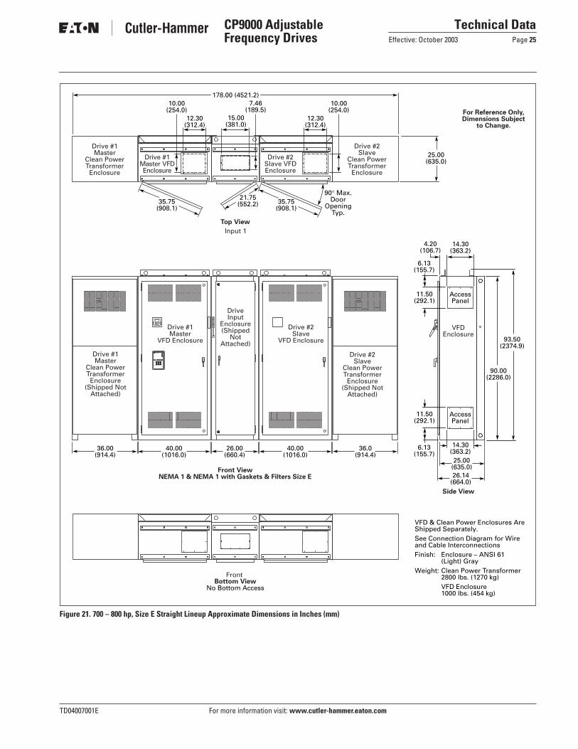
Figure 21. 700 – 800 hp, Size E Straight Lineup Approximate Dimensions in Inches (mm)
For Reference Only,Dimensions Subject
to Change.
35.75(908.1)
Bottom ViewNo Bottom Access
Top View
Drive #2Slave
VFD Enclosure
Drive #1Master
VFD Enclosure
VFDEnclosure
DriveInput
Enclosure(Shipped
NotAttached)
Drive #2Slave
Clean PowerTransformer
Enclosure(Shipped Not
Attached)
Drive #1Master VFDEnclosure
Drive #2Slave VFDEnclosure
Drive #2Slave
Clean PowerTransformer
Enclosure
Drive #1Master
Clean PowerTransformer
Enclosure
Front
Input 1
Drive #1Master
Clean PowerTransformer
Enclosure(Shipped Not
Attached)
10.00(254.0)
7.46(189.5)
10.00(254.0)
12.30(312.4)
25.00(635.0)
178.00 (4521.2)
36.0(914.4)
26.00(660.4)
40.00(1016.0)
40.00(1016.0)
36.00(914.4)
25.00(635.0)26.14
(664.0)
Front ViewNEMA 1 & NEMA 1 with Gaskets & Filters Size E
Side View
12.30(312.4)
15.00(381.0)
VFD & Clean Power Enclosures AreShipped Separately. See Connection Diagram for Wireand Cable Interconnections Finish: Enclosure – ANSI 61
(Light) Gray Weight: Clean Power Transformer
2800 lbs. (1270 kg) VFD Enclosure1000 lbs. (454 kg)
35.75(908.1)
21.75(552.2)
90° Max.Door
OpeningTyp.
MP-3000
90.00(2286.0)
93.50(2374.9)
AccessPanel
AccessPanel
14.30(363.2)
6.13(155.7)
14.30(363.2)
11.50(292.1)
6.13(155.7)
11.50(292.1)
4.20(106.7)

For more information visit: www.cutler-hammer.eaton.com TD04007001E
Technical DataPage 26 Effective: October 2003
CP9000 Adjustable Frequency Drives
Figure 22. 700 – 800 hp, Size E Back to Back Approximate Dimensions in Inches (mm)
For Reference Only, Dimensions Subject
to Change.
35.75(908.1)
Bottom ViewNo Bottom Access
Top View
MasterVFD Enclosure
SlaveClean PowerTransformerEnclosure
InputEnclosure
InputEnclosure(Shipped
NotAttached)
Master VFDEnclosure
Slave VFDEnclosure
SlaveClean PowerTransformer
Enclosure
MasterClean PowerTransformer
Enclosure
Rear
Front
Rear
Input 1
Front
MasterClean PowerTransformer
Enclosure(Shipped Not
Attached)
7.46(189.5)
6.00(152.4)
10.00(254.0)Typ. 2Places
56.00(1421.8)
102.00 (2590.8)76.00 (1930.4)
90.00(2286.0)
26.00(660.4)
40.00(1016.0)
36.00(914.4)
25.00(635.0)
26.29(667.8)
25.00(635.0)
26.29(667.8)
6.00(152.4)
Front View NEMA 1 & NEMA 1 with Gaskets & Filters Size E
Side View
15.00(381.0)
12.30 (312.4)Typ. 2 Places
VFD & Clean Power Enclosures AreShipped Separately. See Connection Diagram for Wireand Cable Interconnections Finish: Enclosure – ANSI 61 (Light) Gray Weight: Clean Power Transformer 2800 lbs. (1270 kg) VFD Enclosure 1000 lbs. (454 kg)
21.75(552.2)
35.75(908.1)
90° Max.Door
OpeningTyp.
93.50(2374.9)
Access Panel
Access Panel
14.30 (363.2)
14.30 (363.2)
4.20 (106.7)
6.13 (155.7)
11.50 (292.1)
6.13 (155.7)
11.50 (292.1)
TD04007001E For more information visit: www.cutler-hammer.eaton.com
Technical DataEffective: October 2003 Page 27
CP9000 Adjustable Frequency Drives
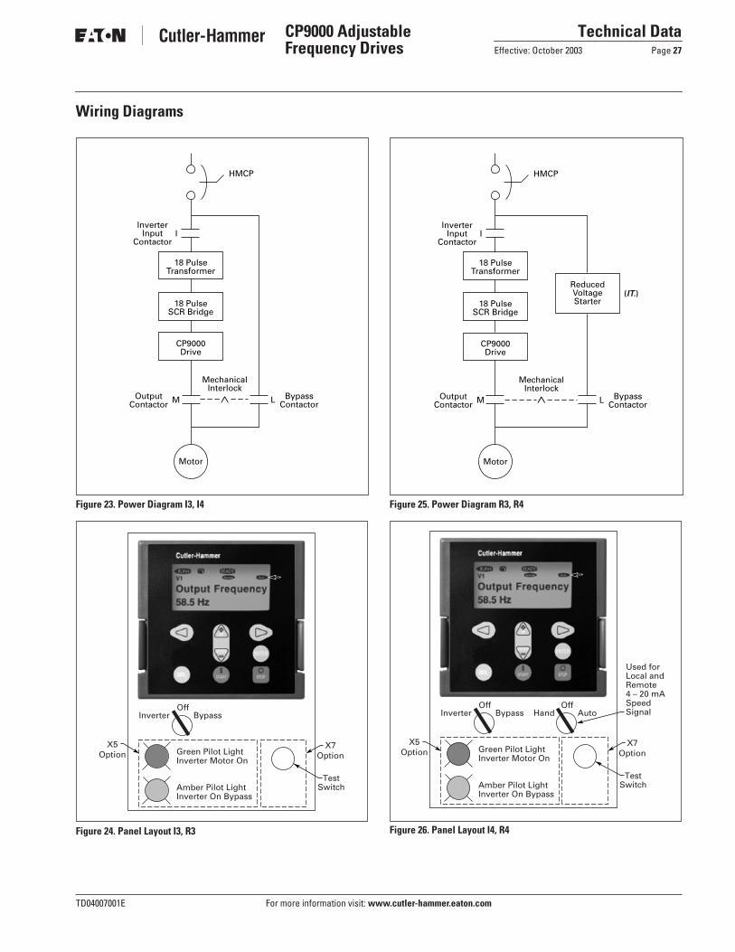
Wiring Diagrams
Figure 23. Power Diagram I3, I4
Figure 24. Panel Layout I3, R3
Figure 25. Power Diagram R3, R4
Figure 26. Panel Layout I4, R4
18 PulseTransformer
18 PulseSCR Bridge
CP9000Drive
HMCP
OutputContactor
BypassContactor
MechanicalInterlock
Motor
M L
InverterInput
ContactorI
X5Option
X7Option
Inverter Bypass
Green Pilot LightInverter Motor On
Amber Pilot LightInverter On Bypass
TestSwitch
Off
18 PulseTransformer
ReducedVoltageStarter18 Pulse
SCR Bridge
CP9000Drive
HMCP
OutputContactor
MechanicalInterlock
Motor
M
InverterInput
ContactorI
(IT.)
BypassContactorL
Inverter Bypass
Green Pilot LightInverter Motor On
Amber Pilot LightInverter On Bypass
OffHand Auto
Off
Used forLocal andRemote4 – 20 mASpeedSignal
X5Option
X7Option
TestSwitch

Technical DataPage 28 Effective: October 2003
CP9000 Adjustable Frequency Drives
© 2003 Eaton CorporationAll Rights ReservedPrinted in USAPublication No. TD04007001E/CPGOctober 2003
Eaton CorporationCutler-Hammer business unit1000 Cherrington ParkwayMoon Township, PA 15108-4312USAtel: 1-800-525-2000www.cutler-hammer.eaton.com

![Repair Information - Eatonpub/@eaton/@hyd/documents/co… · Eaton May 1999 ® Medium Duty Piston Pump Repair Information Model 74624 and 74644, 82,6 cm3/r [5.04 in3/r] Displacement](https://static.fdocuments.in/doc/165x107/5b5784017f8b9ac31e8d9d73/repair-information-pubeatonhyddocumentsco-eaton-may-1999-medium-duty.jpg)


![Repair Information - Eatonpub/@eaton/@hyd/documents/content/...Repair Information. 2 Power Steering ... ( Circular ) Form Dia. 17,45 [.687] Pitch Dia..7500 [19,05] Fit Flat Root Side](https://static.fdocuments.in/doc/165x107/5aa301e77f8b9ada698da9d0/repair-information-pubeatonhyddocumentscontentrepair-information-2.jpg)