Product Data - Single Packaged Heat Pump Models 4WCC4 · PDF file12-1360-1F-EN 3 Single...
32
December 2015 12-1360-1F-EN Single Packaged Heat Pump 14 SEER Convertible, 2 — 5 Ton 4WCC4024A1000A 4WCC4030A1000A 4WCC4036A1000A 4WCC4042A1000A 4WCC4048A1000A 4WCC4060A1000A Note: “Graphics in this document are for representation only. Actual model may differ in appearance.” Product Data
Transcript of Product Data - Single Packaged Heat Pump Models 4WCC4 · PDF file12-1360-1F-EN 3 Single...

December 2015 12-1360-1F-EN
Single Packaged Heat Pump14 SEER Convertible, 2 — 5 Ton4WCC4024A1000A
4WCC4030A1000A
4WCC4036A1000A
4WCC4042A1000A
4WCC4048A1000A
4WCC4060A1000A
NNoottee:: “Graphics in this document are for representation only. Actualmodel may differ in appearance.”
Product Data

2 12-1360-1F-EN
Single Packaged Heat Pump System. . . . . . . . . . . . . . . . . . . . . . . . . . . . . . . . . . . . . . . . . . . . . . . . . . . . . . . . . . . . . . 3
Optional Equipment Listing. . . . . . . . . . . . . . . . . . . . . . . . . . . . . . . . . . . . . . . . . . . . . . . . . . . . . . . . . . . . . . . . . . . . . . . 4
Product Specifications . . . . . . . . . . . . . . . . . . . . . . . . . . . . . . . . . . . . . . . . . . . . . . . . . . . . . . . . . . . . . . . . . . . . . . . . . . . . 6
Supplementary Electric Heaters . . . . . . . . . . . . . . . . . . . . . . . . . . . . . . . . . . . . . . . . . . . . . . . . . . . . . . . . . . . . . . . . . . 9
Indoor Fan Performance (230v). . . . . . . . . . . . . . . . . . . . . . . . . . . . . . . . . . . . . . . . . . . . . . . . . . . . . . . . . . . . . . . . . . 10
Wiring Diagrams. . . . . . . . . . . . . . . . . . . . . . . . . . . . . . . . . . . . . . . . . . . . . . . . . . . . . . . . . . . . . . . . . . . . . . . . . . . . . . . . . 14
Full Perimeter Roof Mounting Curb . . . . . . . . . . . . . . . . . . . . . . . . . . . . . . . . . . . . . . . . . . . . . . . . . . . . . . . . . . . . . . 18
Optional Equipment — Economizer. . . . . . . . . . . . . . . . . . . . . . . . . . . . . . . . . . . . . . . . . . . . . . . . . . . . . . . . . . . . . . 20
Optional Equipment — Outside Air Damper . . . . . . . . . . . . . . . . . . . . . . . . . . . . . . . . . . . . . . . . . . . . . . . . . . . . . 21
Optional Equipment — Filter Rack . . . . . . . . . . . . . . . . . . . . . . . . . . . . . . . . . . . . . . . . . . . . . . . . . . . . . . . . . . . . . . . 22
Outline Drawings . . . . . . . . . . . . . . . . . . . . . . . . . . . . . . . . . . . . . . . . . . . . . . . . . . . . . . . . . . . . . . . . . . . . . . . . . . . . . . . . 23
Mechanical Specifications . . . . . . . . . . . . . . . . . . . . . . . . . . . . . . . . . . . . . . . . . . . . . . . . . . . . . . . . . . . . . . . . . . . . . . . 29
Table of Contents
12-1360-1F-EN 3
Single Packaged Heat Pump System
American Standard Heating & Air Conditioning offers a complete family of electric heat pump
heating and cooling systems designed to keep you comfortable all year long, regardless of the
weather, while keeping your operating costs as low as possible. A heat pump operates efficiently
as both an air conditioner and a heater. In the summer, the heat pump cools your home just like
any other air conditioner by pulling the heat from the inside and releasing it outdoors. In the
winter, it captures the heat that is always present in the outdoor air and transfers it indoors.
IInnttrroodduucciinngg tthhee nneeww AAmmeerriiccaann SSttaannddaarrdd HHeeaattiinngg && AAiirr CCoonnddiittiioonniinngg SSiinnggllee HHeeaatt PPuummpp
SSyysstteemm
SSiinnggllee PPaacckkaaggeedd EElleeccttrriicc HHeeaatt PPuummppss aarree eeaassyy aanndd vveerrssaattiillee ttoo iinnssttaallll..
Because cooling and heating functions are all contained in a single cabinet, American Standard
Heating & Air Conditioning packaged heat pump systems are easy to install and service. It can be
flush mounted beside your home at ground level or placed on the roof for horizontal or
downflow installation. When connected to an optional American Standard Heating & Air
Conditioning thermostat control, and air distribution ducts, you have a highly efficient, total
home comfort system.
SSiinnggllee PPaacckkaaggeedd EElleeccttrriicc HHeeaatt PPuummpp SSyysstteemmss aarree uunnmmaattcchheedd iinn qquuaalliittyy aanndd rreelliiaabbiilliittyy..
All major components on these products, including the compressor, have been designed and
manufactured for maximum service. Every compressor is designed and manufactured to
exacting specifications. Each design is life tested in extreme environments to ensure reliable and
long lasting operation in normal applications. Each compressor has internal motor protection for
added reliability.
SSiinnggllee PPaacckkaaggeedd EElleeccttrriicc HHeeaatt PPuummpp SSyysstteemmss pprroovviiddee bbeetttteerr ppeerrffoorrmmaannccee..
Our single packaged cooling/heating units offer cooling/heating efficiencies that are unmatched
in the industry and provide you with a product far superior in performance than the competition.
4 12-1360-1F-EN
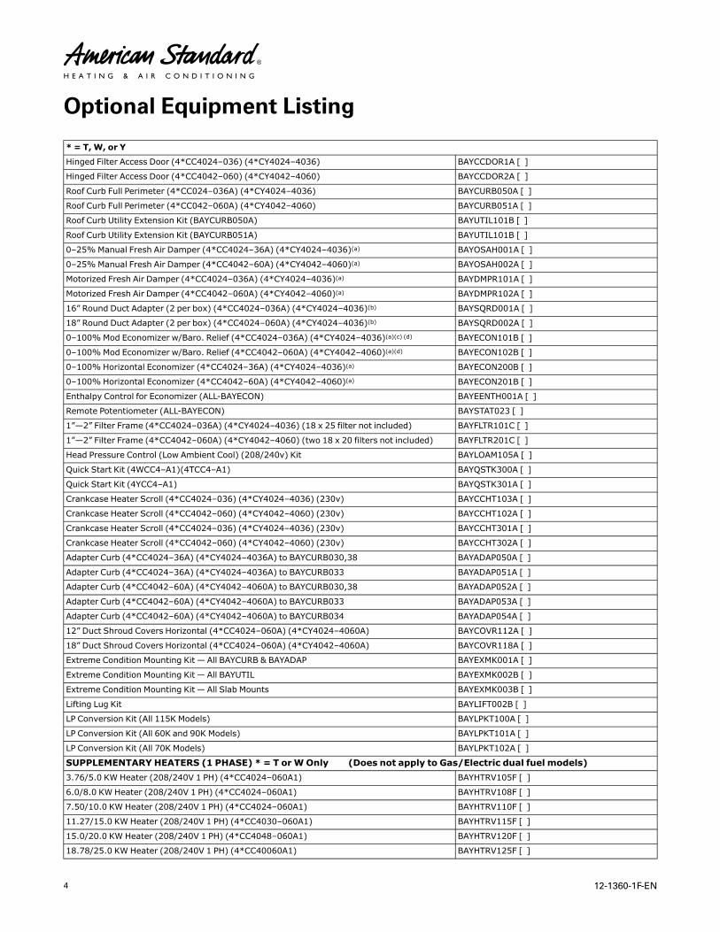
Optional Equipment Listing
* = T,W, or Y
Hinged Filter Access Door (4*CC4024–036) (4*CY4024–4036) BAYCCDOR1A [ ]
Hinged Filter Access Door (4*CC4042–060) (4*CY4042–4060) BAYCCDOR2A [ ]
Roof Curb Full Perimeter (4*CC024–036A) (4*CY4024–4036) BAYCURB050A [ ]
Roof Curb Full Perimeter (4*CC042–060A) (4*CY4042–4060) BAYCURB051A [ ]
Roof Curb Utility Extension Kit (BAYCURB050A) BAYUTIL101B [ ]
Roof Curb Utility Extension Kit (BAYCURB051A) BAYUTIL101B [ ]
0–25%Manual Fresh Air Damper (4*CC4024–36A) (4*CY4024–4036)(a) BAYOSAH001A [ ]
0–25%Manual Fresh Air Damper (4*CC4042–60A) (4*CY4042–4060)(a) BAYOSAH002A [ ]
Motorized Fresh Air Damper (4*CC4024–036A) (4*CY4024–4036)(a) BAYDMPR101A [ ]
Motorized Fresh Air Damper (4*CC4042–060A) (4*CY4042–4060)(a) BAYDMPR102A [ ]
16” Round Duct Adapter (2 per box) (4*CC4024–036A) (4*CY4024–4036)(b) BAYSQRD001A [ ]
18” Round Duct Adapter (2 per box) (4*CC4024–060A) (4*CY4024–4036)(b) BAYSQRD002A [ ]
0–100%Mod Economizer w/Baro. Relief (4*CC4024–036A) (4*CY4024–4036)(a)(c) (d) BAYECON101B [ ]
0–100%Mod Economizer w/Baro. Relief (4*CC4042–060A) (4*CY4042–4060)(a)(d) BAYECON102B [ ]
0–100% Horizontal Economizer (4*CC4024–36A) (4*CY4024–4036)(a) BAYECON200B [ ]
0–100% Horizontal Economizer (4*CC4042–60A) (4*CY4042–4060)(a) BAYECON201B [ ]
Enthalpy Control for Economizer (ALL-BAYECON) BAYEENTH001A [ ]
Remote Potentiometer (ALL-BAYECON) BAYSTAT023 [ ]
1”—2” Filter Frame (4*CC4024–036A) (4*CY4024–4036) (18 x 25 filter not included) BAYFLTR101C [ ]
1”—2” Filter Frame (4*CC4042–060A) (4*CY4042–4060) (two 18 x 20 filters not included) BAYFLTR201C [ ]
Head Pressure Control (Low Ambient Cool) (208/240v) Kit BAYLOAM105A [ ]
Quick Start Kit (4WCC4–A1)(4TCC4–A1) BAYQSTK300A [ ]
Quick Start Kit (4YCC4–A1) BAYQSTK301A [ ]
Crankcase Heater Scroll (4*CC4024–036) (4*CY4024–4036) (230v) BAYCCHT103A [ ]
Crankcase Heater Scroll (4*CC4042–060) (4*CY4042–4060) (230v) BAYCCHT102A [ ]
Crankcase Heater Scroll (4*CC4024–036) (4*CY4024–4036) (230v) BAYCCHT301A [ ]
Crankcase Heater Scroll (4*CC4042–060) (4*CY4042–4060) (230v) BAYCCHT302A [ ]
Adapter Curb (4*CC4024–36A) (4*CY4024–4036A) to BAYCURB030,38 BAYADAP050A [ ]
Adapter Curb (4*CC4024–36A) (4*CY4024–4036A) to BAYCURB033 BAYADAP051A [ ]
Adapter Curb (4*CC4042–60A) (4*CY4042–4060A) to BAYCURB030,38 BAYADAP052A [ ]
Adapter Curb (4*CC4042–60A) (4*CY4042–4060A) to BAYCURB033 BAYADAP053A [ ]
Adapter Curb (4*CC4042–60A) (4*CY4042–4060A) to BAYCURB034 BAYADAP054A [ ]
12” Duct Shroud Covers Horizontal (4*CC4024–060A) (4*CY4024–4060A) BAYCOVR112A [ ]
18” Duct Shroud Covers Horizontal (4*CC4024–060A) (4*CY4042–4060A) BAYCOVR118A [ ]
Extreme Condition Mounting Kit — All BAYCURB & BAYADAP BAYEXMK001A [ ]
Extreme Condition Mounting Kit — All BAYUTIL BAYEXMK002B [ ]
Extreme Condition Mounting Kit — All Slab Mounts BAYEXMK003B [ ]
Lifting Lug Kit BAYLIFT002B [ ]
LP Conversion Kit (All 115K Models) BAYLPKT100A [ ]
LP Conversion Kit (All 60K and 90K Models) BAYLPKT101A [ ]
LP Conversion Kit (All 70K Models) BAYLPKT102A [ ]
SUPPLEMENTARY HEATERS (1 PHASE) * = T orWOnly (Does not apply to Gas/Electric dual fuel models)3.76/5.0 KW Heater (208/240V 1 PH) (4*CC4024–060A1) BAYHTRV105F [ ]
6.0/8.0 KW Heater (208/240V 1 PH) (4*CC4024–060A1) BAYHTRV108F [ ]
7.50/10.0 KW Heater (208/240V 1 PH) (4*CC4024–060A1) BAYHTRV110F [ ]
11.27/15.0 KW Heater (208/240V 1 PH) (4*CC4030–060A1) BAYHTRV115F [ ]
15.0/20.0 KW Heater (208/240V 1 PH) (4*CC4048–060A1) BAYHTRV120F [ ]
18.78/25.0 KW Heater (208/240V 1 PH) (4*CC40060A1) BAYHTRV125F [ ]

12-1360-1F-EN 5
SUPPLEMENTARY HEATERS (3 PHASE) * = T orWOnly (Does not apply to Gas/Electric dual fuel models)3.76/5.0 KW Heater (208/240V 3 PH) (4WCY4036–060A3) BAYHTRV305F [ ]
3.76/5.0 KW Heater (208/240V 3 PH) (4WCY4036–060A3) BAYHTRV308F [ ]
7.50/10.0 KW Heater (208/240V 3 PH) (4WCY4024–048A3) BAYHTRV310F [ ]
11.27/15.0 KW Heater (208/240V 3 PH) (4WCY4036–060A3) BAYHTRV315F [ ]
15.0/20.0 KW Heater (208/240V 3 PH) (4WCY4048–060A3) BAYHTRV320F [ ]
18.78/25.0 KW Heater (208/240V 3 PH) (4WCY4048–060A1) BAYHTRV325F [ ]
Single Power Entry Kit (e) BAYSPEK060F [ ]
Single Power Entry Kit (e) BAYSPEK061E [ ]
Single Power Entry Kit (e) BAYSPEK062F [ ]
Single Power Entry Kit (e) BAYSPEK063F [ ]
Single Power Entry Kit (e) BAYSPEK064E [ ]
Single Power Entry Kit (e) BAYSPEK065E [ ](a) Must use internal filter frame when economizer or fresh air kit is used.(b) It is the responsibility of the installing dealer to properly size the ductwork for each specific application.(c) Dry bulb control standard with economizer.(d) Downflow only.(e) Must be selected per unit and heater model
OOppttiioonnaall EEqquuiippmmeenntt LLiissttiinngg

6 12-1360-1F-EN
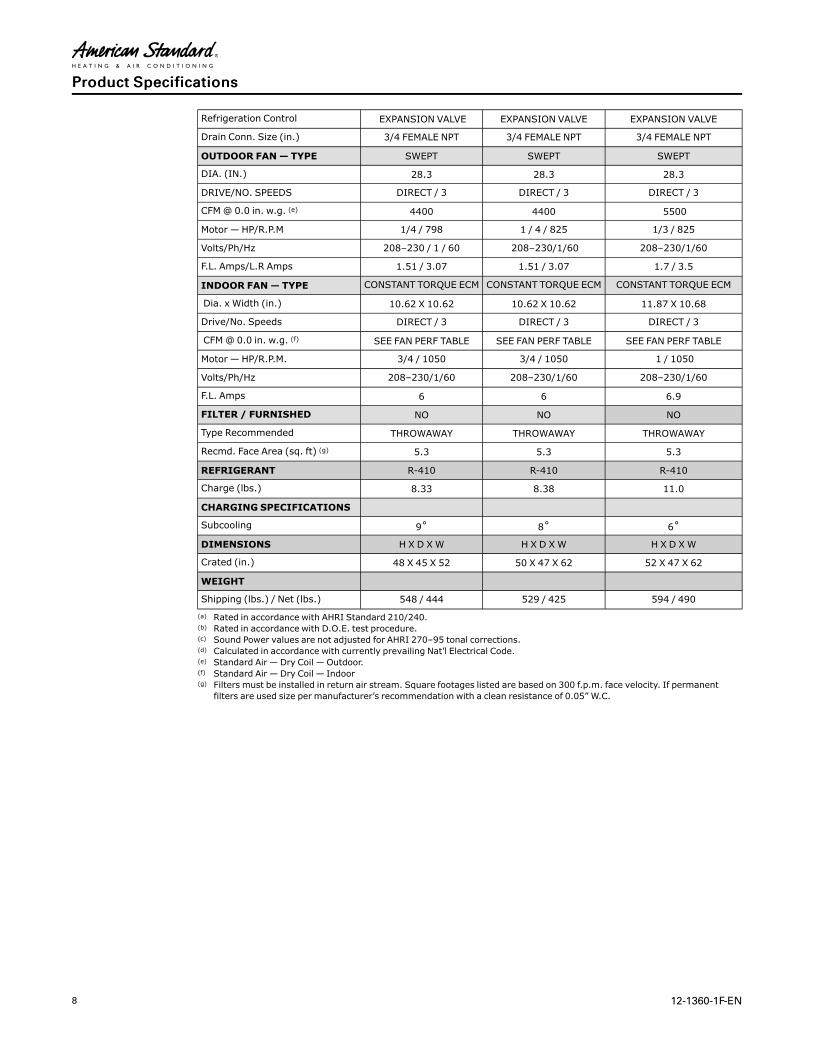
Product Specifications
MODEL 4WCC4024A1000A 4WCC4030A1000A 4WCC4036A1000A
RATED Volts/PH/Hz 208–230/1/60 208–230/1/60 208–230/1/60
Performance Cooling BTUH (a) 24600 30400 35800
Indoor Airflow (CFM) 758 985 1114
Power Input (KW) 1.9 2.41 2.8
EER/SEER (BTU/Watt-Hr.) (b) 12.00 / 14.00 12.00 / 14.00 12.00 / 14.00
Sound Power Rating [dB(A)] (c) 66.4 70.0 69.4
PERFORMANCE HEATING
(High Temp.) BTUH 22000 27200 32600
Power Input (KW) 1.8 2.1 2.7
(Low Temp.) BTUH 14300 16,700 21,800
Power Input (KW) 1.12 1.25 1.75
HSPF (BTUH/Watt-Hr) 8.0 8.0 8.0
POWER CONN.— V/Ph/Hz 208–230/1/60 208–230/1/60 208–230/1/60
Min. Brch. Cir. Ampacity (d) 19.4 22.6 24.4
Fuse Size — Max. (amps) 30 35 40
Fuse Size — Recmd. (amps) 30 35 40
COMPRESSOR SCROLL SCROLL SCROLL
VOLTS/PH/HZ 208–230/1/60 208–230/1/60 208–230/1/60
R.L. Amps — L.R. Amps 12.8 / 58.3 14.1 / 68.2 15.4 / 77.0
OUTDOOR COIL — TYPE SPINE FIN SPINE FIN SPINE FIN
Rows/F.P.I 2 / 24 2 / 24 2 / 24
Face Area (sq. ft.) 13.32 13.32 15.49
Tube Size (in.) 3/8 3/8 3/8
Refrigerant Control EXPANSION VALVE EXPANSION VALVE EXPANSION VALVE
INDOOR COIL — TYPE PLATE FIN PLATE FIN PLATE FIN
Rows/F.P.I 3 / 15 4/ 15 4 / 15
Face Area (sq. ft.) 3.5 3.5 3.5
Tube Size (in.) 3/8 3/8 3/8
Refrigeration Control EXPANSION VALVE EXPANSION VALVE EXPANSION VALVE
Drain Conn. Size (in.) 3/4 FEMALE NPT 3/4 FEMALE NPT 3/4 FEMALE NPT
OUTDOOR FAN— TYPE SWEPT SWEPT SWEPT
DIA. (IN.) 23.4 23.4 23.4
DRIVE/NO. SPEEDS DIRECT / 3 DIRECT / 3 DIRECT / 3
CFM@ 0.0 in. w.g. (e) 2550 3270 3250
Motor — HP/R.P.M 1/12 / 850 1/6/ 842 1 / 5 / 855
Volts/Ph/Hz 208–230/1/60 208–230/1/60 208–230 / 1 / 60
F.L. Amps/L.R Amps .54 / .82 .85 / 1.65 1.1 / 2.0
INDOOR FAN— TYPE CONSTANT TORQUE ECM CONSTANT TORQUE ECM CONSTANT TORQUE ECM
Dia. x Width (in.) 10.62 X 10.68 10.62 X 10.68 10.62 X 10.68
Drive/No. Speeds DIRECT / 3 DIRECT / 3 DIRECT / 3
CFM@ 0.0 in. w.g. (f) SEE FAN PERF TABLE SEE FAN PERF TABLE SEE FAN PERF TABLE
Motor — HP/R.P.M. 1/3 / 1050 1/2 / 1050 1/2 / 1050
Volts/Ph/Hz 208–230/1/60 208–230/1/60 208–230/1/60

12-1360-1F-EN 7
F.L. Amps 2.8 4 4.1
FILTER / FURNISHED NO NO NO
Type Recommended THROWAWAY THROWAWAY THROWAWAY
Recmd. Face Area (sq. ft) (g) 2.7 4.0 4.0
REFRIGERANT R-410 R-410 R-410
Charge (lbs.) 5.74 7.2 7.2
CHARGING SPECIFICATIONS
Subcooling 16˚ 14˚ 11˚
DIMENSIONS H X D XW H X D XW H X D XW
Crated (in.) 46 X 45 X 52 48 X 45 X 52 48 X 45 X 52
WEIGHT
Shipping (lbs.) / Net (lbs.) 402 / 328 430 / 355 439 / 364(a) Rated in accordance with AHRI Standard 210/240.(b) Rated in accordance with D.O.E. test procedure.(c) Sound Power values are not adjusted for AHRI 270–95 tonal corrections.(d) Calculated in accordance with currently prevailing Nat’l Electrical Code.(e) Standard Air — Dry Coil — Outdoor.(f) Standard Air — Dry Coil — Indoor(g) Filters must be installed in return air stream. Square footages listed are based on 300 f.p.m. face velocity. If permanent
filters are used size per manufacturer’s recommendation with a clean resistance of 0.05” W.C.
MODEL 4WCC4042A1000A 4WCC4048A1000A 4WCC4060A1000A
RATED Volts/PH/Hz 208–230/1/60 208–230/1/60 208–230/1/60
Performance Cooling BTUH (a) 43000 48000 58000
Indoor Airflow (CFM) 1367 1423 1787
Power Input (KW) 3.5 3.9 4.6
EER/SEER (BTU/Watt-Hr.) (b) 12.00 / 14.00 12.00 / 14.00 12.00 / 14.00
Sound Power Rating [dB(A)] (c) 71.5 72.5 77.3
PERFORMANCE HEATING
(High Temp.) BTUH 37,600 43500 54000
Power Input (KW) 3.45 3.7 4.6
(Low Temp.) BTUH 22800 25400 34600
Power Input (KW) 1.94 2.10 2.80
HSPF (BTUH/Watt-Hr) 8.0 8.0 8.0
POWER CONN.— V/Ph/Hz 208–230/1/60 208–230/1/60 208–230/1/60
Min. Brch. Cir. Ampacity (d) 28.3 31.9 39.0
Fuse Size — Max. (amps) 45 50 60
Fuse Size — Recmd. (amps) 45 50 60
COMPRESSOR SCROLL SCROLL SCROLL
VOLTS/PH/HZ 208–230/1/60 208–230/1/60 208–230/1/60
R.L. Amps — L.R. Amps 16.7 / 123.9 19.6 / 130.0 24.4/ 144.2
OUTDOOR COIL — TYPE SPINE FIN SPINE FIN SPINE FIN
Rows/F.P.I 2 / 24 2 / 24 2 / 24
Face Area (sq. ft.) 20.54 20.54 22.99
Tube Size (in.) 3/8 3/8 3/8
Refrigerant Control EXPANSION VALVE EXPANSION VALVE EXPANSION VALVE
INDOOR COIL — TYPE PLATE FIN PLATE FIN PLATE FIN
Rows/F.P.I 3 / 15 3 / 15 4 / 15
Face Area (sq. ft.) 5.0 5.0 5.0
Tube Size (in.) 3/8 3/8 3/8
PPrroodduucctt SSppeecciiffiiccaattiioonnss
8 12-1360-1F-EN
Refrigeration Control EXPANSION VALVE EXPANSION VALVE EXPANSION VALVE
Drain Conn. Size (in.) 3/4 FEMALE NPT 3/4 FEMALE NPT 3/4 FEMALE NPT
OUTDOOR FAN— TYPE SWEPT SWEPT SWEPT
DIA. (IN.) 28.3 28.3 28.3
DRIVE/NO. SPEEDS DIRECT / 3 DIRECT / 3 DIRECT / 3
CFM@ 0.0 in. w.g. (e) 4400 4400 5500
Motor — HP/R.P.M 1/4 / 798 1 / 4 / 825 1/3 / 825
Volts/Ph/Hz 208–230 / 1 / 60 208–230/1/60 208–230/1/60
F.L. Amps/L.R Amps 1.51 / 3.07 1.51 / 3.07 1.7 / 3.5
INDOOR FAN— TYPE CONSTANT TORQUE ECM CONSTANT TORQUE ECM CONSTANT TORQUE ECM
Dia. x Width (in.) 10.62 X 10.62 10.62 X 10.62 11.87 X 10.68
Drive/No. Speeds DIRECT / 3 DIRECT / 3 DIRECT / 3
CFM@ 0.0 in. w.g. (f) SEE FAN PERF TABLE SEE FAN PERF TABLE SEE FAN PERF TABLE
Motor — HP/R.P.M. 3/4 / 1050 3/4 / 1050 1 / 1050
Volts/Ph/Hz 208–230/1/60 208–230/1/60 208–230/1/60
F.L. Amps 6 6 6.9
FILTER / FURNISHED NO NO NO
Type Recommended THROWAWAY THROWAWAY THROWAWAY
Recmd. Face Area (sq. ft) (g) 5.3 5.3 5.3
REFRIGERANT R-410 R-410 R-410
Charge (lbs.) 8.33 8.38 11.0
CHARGING SPECIFICATIONS
Subcooling 9˚ 8˚ 6˚
DIMENSIONS H X D XW H X D XW H X D XW
Crated (in.) 48 X 45 X 52 50 X 47 X 62 52 X 47 X 62
WEIGHT
Shipping (lbs.) / Net (lbs.) 548 / 444 529 / 425 594 / 490
(a) Rated in accordance with AHRI Standard 210/240.(b) Rated in accordance with D.O.E. test procedure.(c) Sound Power values are not adjusted for AHRI 270–95 tonal corrections.(d) Calculated in accordance with currently prevailing Nat’l Electrical Code.(e) Standard Air — Dry Coil — Outdoor.(f) Standard Air — Dry Coil — Indoor(g) Filters must be installed in return air stream. Square footages listed are based on 300 f.p.m. face velocity. If permanent
filters are used size per manufacturer’s recommendation with a clean resistance of 0.05” W.C.
PPrroodduucctt SSppeecciiffiiccaattiioonnss

12-1360-1F-EN 9
Supplementary Electric Heaters
UNIT MODELELECTRICHEATERMODEL
RATEDVOLT-AGE
PHASE AMPS
HEATERCAPACITY NO.
OFSTAGES
KW/STAGEMCA
MAX. FUSEOR HACRCKT BKRSIZE (a)
CANADAONLYMAX.CKT BKRSIZE (b)KW BTUH 1 2
W/TC*3018–060‡1W/TCY4024–060‡1WCZ6036–060‡1*CC4018–060‡1
BAYHTRV105 208/240 1 18/
213.76/5.0
12800/17100 1 3.76/
5.0 — 23/26 25/30 25/30
W/TC*3018–060‡1W/TCY4024–060‡1WCZ6036–060‡1*CC4018–060‡1
BAYHTRV108 208/240 1 29/
336.0/8.0
20500/27300 1 6.0/
8.0 — 36/41
40/45 40/45
W/TC*3024–060‡1W/TCY4024–060‡1WCZ6036–060‡1*CC4024–060‡1
BAYHTRV110 208/240 1 36/
427.5/10.0
25600/34100 1 7.5/
10.0 — 45/52 45/60 45/60
W/TC*3030–060‡1W/TCY4030–060‡1WCZ6036–060‡1*CC4030–060‡1
BAYHTRV115 208/240 1 54/
6311.27/15.0
38500/51200 2 7.5/
10.03.76/5.0
68/78 70/80 70/80
W/TC*3042–060‡1W/TCY4042–060‡1WCZ6048–060‡1*CC4042–060‡1
BAYHTRV120# 208/240 1 72/
8315.0/20.0
51200/68300 2 7.5/
10.07.5/10.0
90/104 90/110 90/110
WC*3042‡1W/TC3060‡1WTCY4042–060‡1WCZ6048–060‡*CC4060‡1
BAYHTRV125# 208/240 1 90/
10418.78/25.0
51200/68300 2 11.26/
15.07.5/10.0
113/130 125/150 125/150
W/TC*3036-060‡3W/TCY4036-060‡3WCZ6036-060‡3*CC4036-060‡3
BAYHTRV305 208/240 3 10/
123.76/5.0
64100/85300 1 3.76/
5.0 — 13/15 15/15 15/15
W/TC*3036-060‡3W/TCY4036-060‡3WCZ6036-060‡3*CC4036-060‡3
BAYHTRV308 208/240 3 17/
196.0/8.0
20500/27300 1 6.0/
8.0 — 21/24
25/25 25/25
W/TC*3036-060‡3W/TCY4036-060‡3WCZ6036-060‡3*CC4036-060‡3
BAYHTRV310 208/240 3 21/
247.5/10.0
25600/34100 1 7.5/
10.0 — 26/30 30/30 30/30
W/TC*3036-060‡3W/TCY4036-060‡3WCZ6036-060‡3*CC4036-060‡3
BAYHTRV315 208/240 3 31/
3611.27/15.0
38500/51200 2 7.5/
10.03.76/5.0
39/45 40/45 40/45
W/TC*3048-060‡3W/TCY4048-060‡3WCZ6048-060‡3*CC4048-060‡3
BAYHTRV320 208/240 3 42/
4815.0/20.0
51200/68300 2 7.5/
10.07.5/10.0
52/60 60/60 60/60
W/TC*3060‡3W/TCY4048-060‡3WCZ6048-060‡3*CC4060‡3
BAYHTRV325# 208/240 3 52/
6018.78/25.0
64100/85300 2 11.26/
15.07.5/10.0
65/75 70/80 70/80
W/TC*3036-060‡4WCZ6036-060‡4*CC4036-60‡4
BAYHTRV405 480 3 6 5.0 17100 1 5.0 — 8 15 15
W/TC*3036-060‡4WCZ6036-060‡4*CC4036-60‡4
BAYHTRV408 480 3 10 8.0 27300 1 8.0 — 13 15 15
W/TC*3036-060‡4WCZ6036-060‡4*CC4036-60‡4
BAYHTRV410 480 3 12 10.0 34100 1 10.0 — 15 15 15
W/TC*3036-060‡4WCZ6036-060‡4*CC4036-60‡4
BAYHTRV415 480 3 18 15.0 51200 2 10.0 5.0 23 25 25
W/TC*3048-060‡4WCZ6048-060‡4*CC4048-60‡4
BAYHTRV420 480 3 24 20.0 68300 2 10.0 10.0 30 30 30
10 12-1360-1F-EN
W/TC*3060‡4WCZ6048-060‡4*CC4048-60‡4
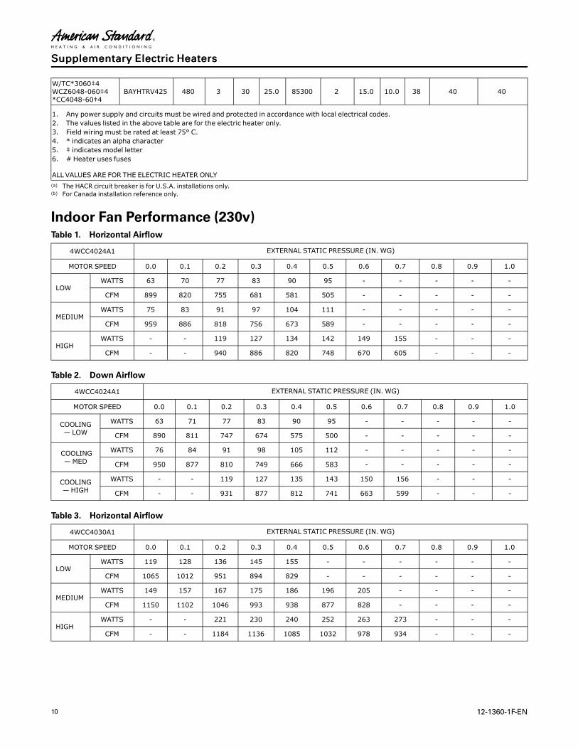
BAYHTRV425 480 3 30 25.0 85300 2 15.0 10.0 38 40 40
1. Any power supply and circuits must be wired and protected in accordance with local electrical codes.2. The values listed in the above table are for the electric heater only.3. Field wiring must be rated at least 75° C.4. * indicates an alpha character5. ‡ indicates model letter6. # Heater uses fuses
ALL VALUES ARE FOR THE ELECTRIC HEATER ONLY(a) The HACR circuit breaker is for U.S.A. installations only.(b) For Canada installation reference only.
Indoor Fan Performance (230v)Table 1. Horizontal Airflow
4WCC4024A1 EXTERNAL STATIC PRESSURE (IN. WG)
MOTOR SPEED 0.0 0.1 0.2 0.3 0.4 0.5 0.6 0.7 0.8 0.9 1.0
LOWWATTS 63 70 77 83 90 95 - - - - -
CFM 899 820 755 681 581 505 - - - - -
MEDIUMWATTS 75 83 91 97 104 111 - - - - -
CFM 959 886 818 756 673 589 - - - - -
HIGHWATTS - - 119 127 134 142 149 155 - - -
CFM - - 940 886 820 748 670 605 - - -
Table 2. Down Airflow
4WCC4024A1 EXTERNAL STATIC PRESSURE (IN. WG)
MOTOR SPEED 0.0 0.1 0.2 0.3 0.4 0.5 0.6 0.7 0.8 0.9 1.0
COOLING— LOW
WATTS 63 71 77 83 90 95 - - - - -
CFM 890 811 747 674 575 500 - - - - -
COOLING—MED
WATTS 76 84 91 98 105 112 - - - - -
CFM 950 877 810 749 666 583 - - - - -
COOLING— HIGH
WATTS - - 119 127 135 143 150 156 - - -
CFM - - 931 877 812 741 663 599 - - -
Table 3. Horizontal Airflow
4WCC4030A1 EXTERNAL STATIC PRESSURE (IN. WG)
MOTOR SPEED 0.0 0.1 0.2 0.3 0.4 0.5 0.6 0.7 0.8 0.9 1.0
LOWWATTS 119 128 136 145 155 - - - - - -
CFM 1065 1012 951 894 829 - - - - - -
MEDIUMWATTS 149 157 167 175 186 196 205 - - - -
CFM 1150 1102 1046 993 938 877 828 - - - -
HIGHWATTS - - 221 230 240 252 263 273 - - -
CFM - - 1184 1136 1085 1032 978 934 - - -
SSuupppplleemmeennttaarryy EElleeccttrriicc HHeeaatteerrss

12-1360-1F-EN 11
Table 4. Down Airflow
4WCC4030A1 EXTERNAL STATIC PRESSURE (IN. WG)
MOTOR SPEED 0.0 0.1 0.2 0.3 0.4 0.5 0.6 0.7 0.8 0.9 1.0
COOLING— LOW
WATTS 120 128 137 145 155 - - - - - -
CFM 1054 1002 942 885 821 - - - - - -
COOLING—MED
WATTS 149 158 167 176 186 197 206 - - - -
CFM 1138 1091 1035 983 928 868 820 - - - -
COOLING— HIGH
WATTS - - 222 231 242 253 264 274 - - -
CFM - - 1173 1124 1074 1022 969 925 - - -
Table 5. Horizontal Airflow
4WCC4036A1 EXTERNAL STATIC PRESSURE (IN. WG)
MOTOR SPEED 0.0 0.1 0.2 0.3 0.4 0.5 0.6 0.7 0.8 0.9 1.0
LOWWATTS 145 152 159 167 175 - - - - - -
CFM 1145 1098 1047 982 926 - - - - - -
MEDIUMWATTS 195 202 210 218 227 236 - - - - -
CFM 1268 1226 1177 1125 1072 1019 - - - - -
HIGHWATTS - - 323 331 342 351 361 372 - - -
CFM - - 1400 1359 1308 1261 1216 1172 - - -
Table 6. Down Airflow
4WCC4036A1 EXTERNAL STATIC PRESSURE (IN. WG)
MOTOR SPEED 0.0 0.1 0.2 0.3 0.4 0.5 0.6 0.7 0.8 0.9 1.0
COOLING— LOW
WATTS 146 153 159 168 176 - - - - - -
CFM 1133 1087 1037 972 916 - - - - - -
COOLING—MED
WATTS 196 203 211 220 228 237 - - - - -
CFM 1255 1213 1166 1114 1062 1009 - - - - -
COOLING— HIGH
WATTS - - 324 333 343 353 363 373 - - -
CFM - - 1386 1346 1295 1248 1204 1160 - - -
Table 7. Horizontal Airflow
4WCC4042A1 EXTERNAL STATIC PRESSURE (IN. WG)
MOTOR SPEED 0.0 0.1 0.2 0.3 0.4 0.5 0.6 0.7 0.8 0.9 1.0
LOWWATTS 257 263 272 282 292 302 311 322 - - -
CFM 1411 1355 1295 1239 1189 1145 1104 1060 - - -
MEDIUMWATTS 370 377 386 398 410 421 431 438 - - -
CFM 1615 1550 1495 1445 1397 1351 1312 1285 - - -
HIGHWATTS - 510 522 531 540 552 565 575 - - -
CFM - 1732 1683 1628 1576 1533 1496 1458 - - -
Table 8. Down Airflow
4WCC4042A1 EXTERNAL STATIC PRESSURE (IN. WG)
MOTOR SPEED 0.0 0.1 0.2 0.3 0.4 0.5 0.6 0.7 0.8 0.9 1.0
SSuupppplleemmeennttaarryy EElleeccttrriicc HHeeaatteerrss

12 12-1360-1F-EN
Table 8. Down Airflow (continued)
COOLING— LOW
WATTS 262 268 277 288 298 308 318 328 - - -
CFM 1397 1342 1282 1226 1177 1134 1093 1049 - - -
COOLING—MED
WATTS 378 384 394 406 418 430 439 447 - - -
CFM 1599 1535 1480 1430 1383 1338 1299 1272 - - -
COOLING— HIGH
WATTS - 520 533 541 551 563 576 586
CFM - 1715 1666 1612 1560 1518 1481 1443 - - -
SSuupppplleemmeennttaarryy EElleeccttrriicc HHeeaatteerrss

12-1360-1F-EN 13
Table 9. Horizontal Airflow
4WCC4048A1 EXTERNAL STATIC PRESSURE (IN. WG)
MOTOR SPEED 0.0 0.1 0.2 0.3 0.4 0.5 0.6 0.7 0.8 0.9 1.0
LOWWATTS 359 371 383 404 406 418 429 440 452 - -
CFM 1649 1616 1581 1516 1509 1475 1441 1408 1374 - -
MEDIUMWATTS 515 525 536 559 562 575 588 600 612 - -
CFM 1871 1827 1789 1731 1724 1693 1661 1630 1600 - -
HIGHWATTS 553 566 577 590 601 613 631 643 647 - -
CFM 1945 1910 1876 1839 1806 1769 1728 1688 1652 - -
Table 10. Down Airflow
4WCC4048A1 EXTERNAL STATIC PRESSURE (IN. WG)
MOTOR SPEED 0.0 0.1 0.2 0.3 0.4 0.5 0.6 0.7 0.8 0.9 1.0
COOLING— LOW
WATTS 367 378 390 412 414 426 438 449 461 - -
CFM 1632 1600 1565 1501 1494 1460 1427 1394 1360 - -
COOLING—MED
WATTS 526 536 547 570 573 586 600 612 625 - -
CFM 1853 1808 1771 1713 1707 1676 1645 1614 1584 - -
COOLING— HIGH
WATTS 564 577 589 602 613 625 644 656 660 - -
CFM 1925 1890 1857 1821 1788 1751 1711 1671 1635 - -
Table 11. Horizontal Airflow
4WCC4060A1 EXTERNAL STATIC PRESSURE (IN. WG)
MOTOR SPEED 0.0 0.1 0.2 0.3 0.4 0.5 0.6 0.7 0.8 0.9 1.0
LOWWATTS 515 523 533 544 554 569 582 595 608 621 -
CFM 1857 1831 1800 1766 1737 1692 1655 1617 1578 1538 -
MEDIUMWATTS 749 759 769 779 788 803 816 830 845 860 874
CFM 2083 2058 2032 2003 1974 1943 1911 1877 1843 1807 1771
HIGHWATTS 910 921 932 941 956 969 983 997 1010 1021
CFM 2177 2152 2127 2105 2071 2041 2009 1975 1940 1903
Table 12. Down Airflow
4WCC4060A1 EXTERNAL STATIC PRESSURE (IN. WG)
MOTOR SPEED 0.0 0.1 0.2 0.3 0.4 0.5 0.6 0.7 0.8 0.9 1.0
COOLING— LOW
WATTS 511 521 533 546 558 570 579 593 606 619
CFM 1875 1841 1805 1766 1730 1696 1668 1628 1568 1527
COOLING—MED
WATTS 745 758 771 786 801 815 829 839 849 858 872
CFM 2104 2063 2034 1999 1965 1931 1894 1869 1846 1795 1759
COOLING— HIGH
WATTS 908 919 930 942 960 971 988 997 1001 1018
CFM 2184 2150 2104 2073 2027 1998 1961 1937 1905 1890
SSuupppplleemmeennttaarryy EElleeccttrriicc HHeeaatteerrss
14 12-1360-1F-EN
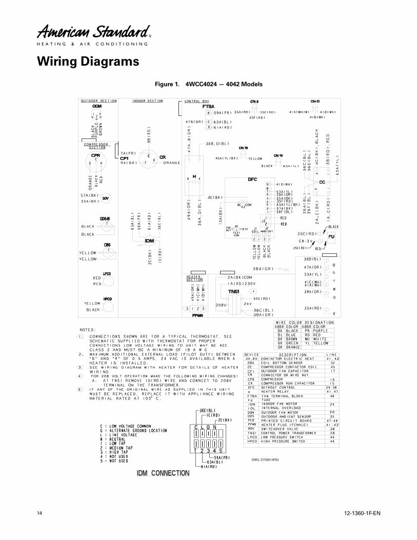
Wiring Diagrams
Figure 1. 4WCC4024 — 4042 Models
DWG. D758014P03

12-1360-1F-EN 15
Figure 2. 4WCC4024 — 4042 Models Pg 2
WWiirriinngg DDiiaaggrraammss
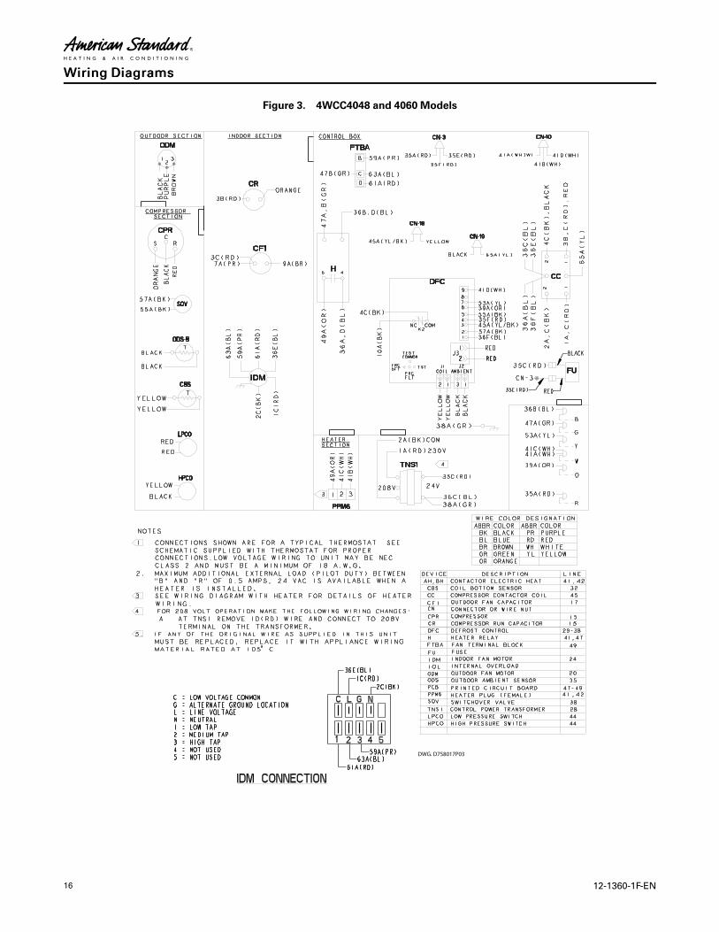
16 12-1360-1F-EN
Figure 3. 4WCC4048 and 4060 Models
DWG. D758017P03
WWiirriinngg DDiiaaggrraammss

12-1360-1F-EN 17
Figure 4. 4WCC4048 and 4060 Models Pg 2
WWiirriinngg DDiiaaggrraammss
18 12-1360-1F-EN
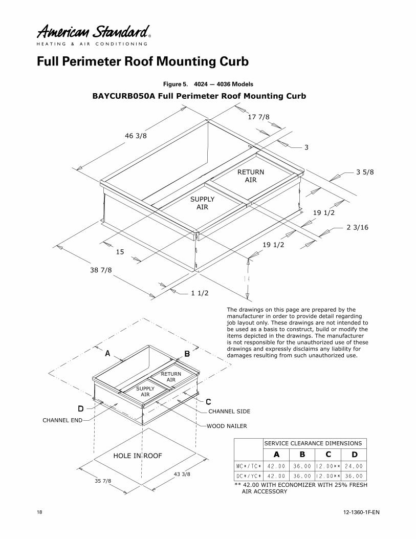
Full Perimeter Roof Mounting Curb
Figure 5. 4024 — 4036 Models
A
1144SUPPLYAIR
RETURNAIR
SUPPLYAIR
RETURNAIR
CHANNEL SIDE
WOOD NAILER
HOLE IN ROOF
CHANNEL END
SERVICE CLEARANCE DIMENSIONS
A B C D
** 42.00 WITH ECONOMIZER WITH 25% FRESH AIR ACCES SORY
The dr awings on this page are prepared by themanufacturer in order to pro vide detail regardingjob la yout only. These drawings are not intended tobe used as a basis to construct, build or modif y theitems depicted in the dr awings. The m anufactureris not responsible for the unauthoriz ed use of thesedrawings and expressly disclaim s any liability fordamages resulting from such unauthoriz ed use.
BAYCURB050A Full Perimeter Roof Mounting Curb
46 3/8
17 7/8
3
15
38 7/8
3 5/8
19 1/2
2 3/16
19 1/2
1 1/2
35 7/843 3/8
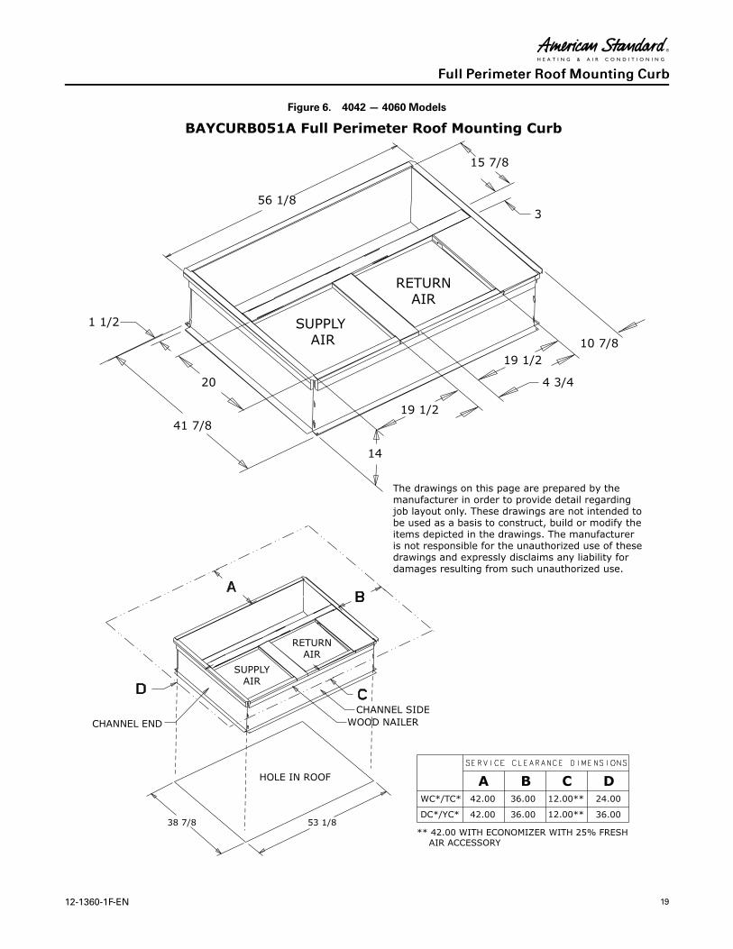
12-1360-1F-EN 19
Figure 6. 4042 — 4060 Models
The dr awings on this page are prepared by themanufacturer in order to pro vide detail regardingjob la yout only. These drawings are not intended tobe used as a basis to construct, build or modif y theitems depicted in the dr awings. The m anufactureris not responsible for the unauthoriz ed use of thesedrawings and expressly disclaim s any liability fordamages resulting from such unauthoriz ed use.
SUPPLYAIR
RETURNAIR
CHANNEL SIDEWOOD NAILER
HOLE IN ROOF
CHANNEL END
WC* / TC*
DC*/YC*
12. 00**
12. 00**42. 00
42. 00
36. 00
36. 00
36. 00
24. 00
* * 42.00 WI TH ECONOMI ZER WI TH 25% FRESH AIR ACCE SSORY
A B DC
SUPPLY AIR
RETURNAIR
BAYCURB051A Full Perimeter Roof Mounting Curb
56 1/8
15 7/8
3
1 1/2
10 7/8
19 1/2
19 1/2
4 3/4
14
20
41 7/8
38 7/8 53 1/8
FFuullll PPeerriimmeetteerr RRooooff MMoouunnttiinngg CCuurrbb
20 12-1360-1F-EN
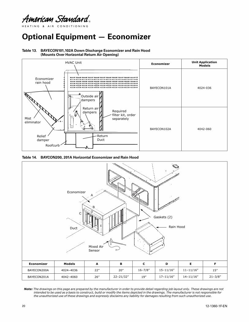
Optional Equipment — Economizer
Table 13. BAYECON101,102A Down Discharge Economizer and Rain Hood(Mounts Over Horizontal Return Air Opening)
HVAC Unit
Economiz errain hood
Outside airdampers
Return airdampers Required
filter kit, ordersepar ately
ReturnDuct
Roofcurb
Reliefdamper
Mist eliminator
Economizer Unit ApplicationModels
BAYECON101A 4024-036
BAYECON102A 4042-060
Table 14. BAYCON200, 201A Horizontal Economizer and Rain Hood
A
B
C D
E
Economiz er
Gask ets (2)
Rain Hood
Mix ed AirSensor
Duct
Economizer Models A B C D E F
BAYECON200A 4024–4036 22” 20” 16–7/8” 15–11/16” 11–11/16” 15”
BAYECON201A 4042–4060 26” 22–21/32” 19” 17–11/16” 14–11/16” 21–3/8”
Note: The drawings on this page are prepared by the manufacturer in order to provide detail regarding job layout only. These drawings are notintended to be used as a basis to construct, build or modify the items depicted in the drawings. The manufacturer is not responsible forthe unauthorized use of these drawings and expressly disclaims any liability for damages resulting from such unauthorized use.

12-1360-1F-EN 21
Optional Equipment — Outside Air Damper
Table 15. BAYOSAH001 and 002A
A
B
CD
FULLYOPEN
2/31/3
FULLYCLOSED
Manual FreshAir Model
UnitApplicationModels
A B C D
BAYOSAH001A 4024 – 4036 22–7/16” 20–11/16” 12–3/8” 9–3/16”
BAYOSAH002A 4042 — 4060 25–3/16” 20–11/16” 12–3/8” 9–3/16”
Table 16. BAYDMPR101 and 102A, 25% Motorized Outside Air Damper(Mounts Over Horizontal Return Air Opening)
D
C B
A
E
ManualFresh AirModel
UnitApplicationModels
A B C D E
BAYDM-PR101A 4024 — 4036 15–13/16” 11–13/16” 10–1/4” 11–1/2” 12–1/4”
BAYDM-PR102A 4042 — 4060 18–3/16” 15–1/8” 10–1/4” 11–1/2” 12–1/4”
Note: The drawings on this page are prepared by the manufacturer in order to provide detail regarding job layout only. These drawings are notintended to be used as a basis to construct, build or modify the items depicted in the drawings. The manufacturer is not responsible forthe unauthorized use of these drawings and expressly disclaims any liability for damages resulting from such unauthorized use.

22 12-1360-1F-EN
Optional Equipment — Filter Rack
Figure 7. BAYFLTR101 Filter Rack (4024–4036)BAYFLTR201 (4042–4060)
(Mounts in Filter/Coil Section)
Figure 8. BAYACCDOR1A Hinged Filter Access Door (4024–4036)BAYACCDOR2A (4042–4060)
Replaces Filter/Coil Access Panel
Note: The drawings on this page are prepared by the manufacturer in order to provide detail regarding job layout only. These drawings are notintended to be used as a basis to construct, build or modify the items depicted in the drawings. The manufacturer is not responsible forthe unauthorized use of these drawings and expressly disclaims any liability for damages resulting from such unauthorized use.

12-1360-1F-EN 23
Outline Drawings
Figure 9. 2 — 3 TONMODELS
Note : The view labeled Bottom Side represents the base as viewed looking up from underneath the unit.

24 12-1360-1F-EN
Figure 10. 2 — 3 TONMODELS
Model Height MM/IN
APPROX. CORNER WEIGHT KG / LBS
SHIPPING WIGHT
KG / LBS
TOTAL UNIT
WEIGHT KG / LBS
CENTER OF GRAVITY MM/IN.
A W1 W2 W3 W4 B C
4TCC4024 898.53 [35 - 3/8]
58.3 [129]
36.8 [81] 26.1 [58]
41.0 [90]
196.1 (432)
162.4 (358)
479.8 [18.9] 527.8 [20.8]
4TCC4030 61.3 [135]
38.7 [85] 27.5 [61]
43.1 [95]
204.8 (451)
171.1 (377)
406.5 [16.0] 594.1 [23.4]
4TCC4036 61.7 [136]
38.9 [86] 27.7 [61]
43.7 [96]
205.7 (453)
172.0 (379)
414.3 [16.3] 697.6 [27.5]
4WCC4024 52.9 [117]
33.3 [73] 24.1 [53]
38.3 [84]
182.3 (402)
148.6 (328)
430 [16.9] 565.3 [22.3]
4WCC4030 55.3 [122] 50.3 [110]
16.6 [37]
39.2 [86]
195.0 (430)
161.3 (355)
413.5 [16.3] 581 [22.9]
4WCC4036 59.6 [131]
37.3 [82] 26.6 [59]
41.7 [92]
199.0 (439)
165.3 (364)
430 [17.0] 535 [21.1]
949.33 [37-3/8]
898.53 [35-3/8]
949.33 [37-3/8]
OOuuttlliinnee DDrraawwiinnggss

12-1360-1F-EN 25
Figure 11. 2 — 3 TONMODELS
OOuuttlliinnee DDrraawwiinnggss

26 12-1360-1F-EN
Figure 12. 3.5 — 5 TONMODELS
Note : The view labeled Bottom Side represents the base as viewed looking up from underneath the unit.
OOuuttlliinnee DDrraawwiinnggss
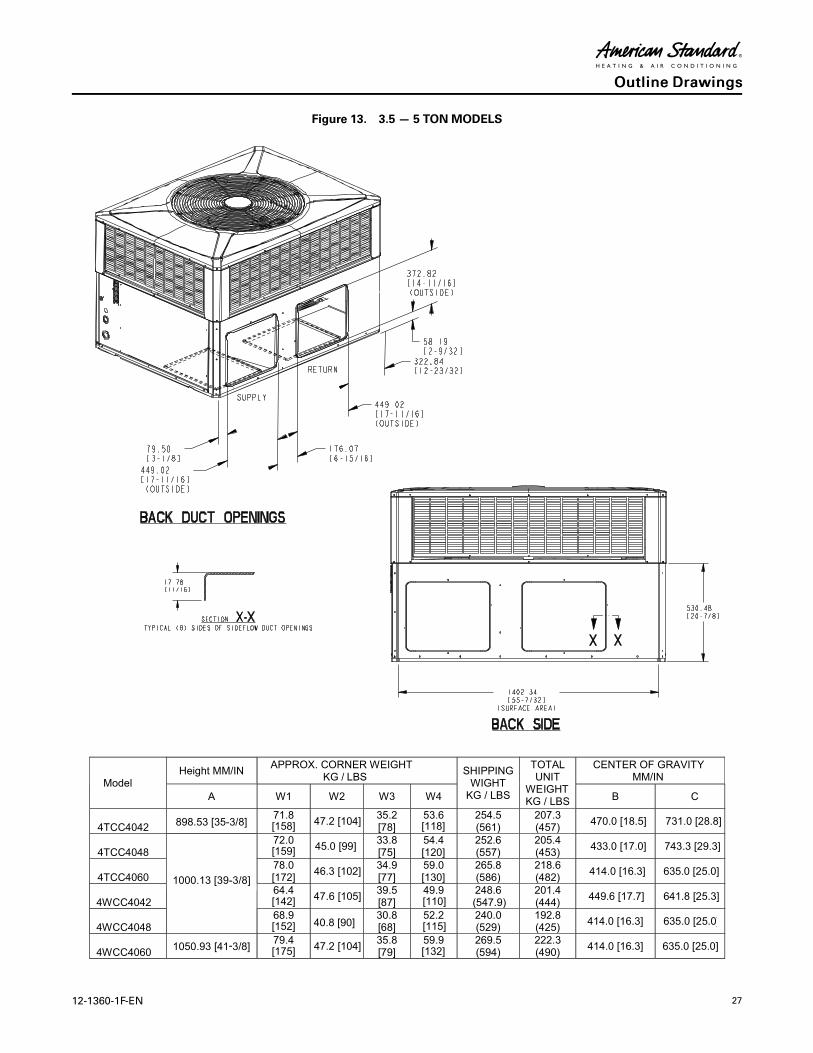
12-1360-1F-EN 27
Figure 13. 3.5 — 5 TONMODELS
Model Height MM/IN
APPROX. CORNER WEIGHT KG / LBS
SHIPPING WIGHT
KG / LBS
TOTAL UNIT
WEIGHT KG / LBS
CENTER OF GRAVITY MM/IN
A W1 W2 W3 W4 B C
4TCC4042 898.53 [35-3/8] 71.8 [158]
47.2 [104] 35.2 [78]
53.6 [118]
254.5 (561)
207.3 (457)
470.0 [18.5] 731.0 [28.8]
4TCC4048 72.0 [159]
45.0 [99] 33.8 [75]
54.4 [120]
252.6 (557)
205.4 (453)
433.0 [17.0] 743.3 [29.3]
4TCC4060 78.0 [172]
46.3 [102] 34.9 [77]
59.0 [130]
265.8 (586)
218.6 (482)
414.0 [16.3] 635.0 [25.0]
4WCC4042 64.4 [142]
47.6 [105] 39.5 [87]
49.9 [110]
248.6 (547.9)
201.4 (444)
449.6 [17.7] 641.8 [25.3]
4WCC4048
1050.93 [41-3/8]
68.9 [152] 40.8 [90]
30.8 [68]
52.2 [115]
240.0 (529)
192.8 (425)
414.0 [16.3] 635.0 [25.0]
4WCC4060 79.4[175]
47.2 [104] 35.8 [79]
59.9 [132]
269.5 (594)
222.3 (490)
414.0 [16.3] 635.0 [25.0]
1000.13 [39-3/8]
OOuuttlliinnee DDrraawwiinnggss
28 12-1360-1F-EN
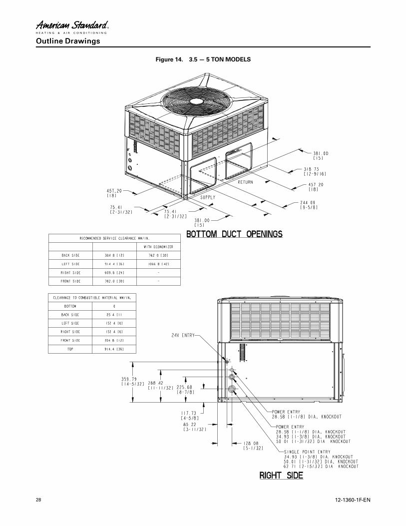
Figure 14. 3.5 — 5 TONMODELS
OOuuttlliinnee DDrraawwiinnggss

12-1360-1F-EN 29
Mechanical Specifications
GGeenneerraall
The units shall be horizontal airflow as shipped and convertible to downflow. All units shall be
factory assembled, piped, internally wired and fully charged with refrigerant. Units shall be
certified to UL Standard 1995. All units shall be factory run tested to check cooling operation, fan
and blower rotation and control or TXV sequence. Units shall be designed to operate at ambient
temperatures between 115°F and 55°F in cooling as manufactured. Cooling performance shall be
rated in accordance with AHRI standards.
UUnniitt CCaassiinngg
All components shall be mounted in a weather-resistant steel cabinet with an enamel finish.
Access panels shall be provided for unit controls and indoor coil and fans. Indoor air section
compartment shall be completely insulated with fireproof, permanent, odorless fiber material.
Knockouts shall be provided for utility and control connections. Drain connections shall be
provided to accommodate indoor water runoff.
CCoommpprreessssoorr
The compressor shall be hermetically sealed, high efficiency scroll compressors. Internal
overcurrent and over temperature protection, internal pressure relief shall be standard. Other
features include centrifugal oil pump, low vibration and noise.
RReeffrriiggeerraattiioonn SSyysstteemm
All units shall have refrigerant control. Service pressure tap ports and a refrigerant line filter shall
be standard.
EEvvaappoorraattoorr CCooiill Internally enhanced 3/8” OD seamless copper tubing mechanically bonded to
aluminum fins, factory pressure and leak tested at 480 – 650 psig. All units have TXV to control
refrigerant flow.
CCoonnddeennsseerr CCooiill
The Spine Fin ™ condenser coil shall be continuously wrapped, corrosion resistant all aluminum
with minimum brazed joints. This coil is 3/8” OD seamless aluminum tubing glued to a
continuous aluminum fin. Coils are lab tested to withstand 2.000 pounds of pressure per square
inch. The outdoor coil provides low airflow resistance and efficient heat transfer. The coil is
protected on all four sides by louvered panels.
IInnddoooorr AAiirr FFaann
Constant Torgue, forward-curved, centrifugal wheel in a Composite Vortica ® Blower housing.
Motor shall have thermal overload protection and permanently lubricated motor bearings.
Motor/blower assembly isolated from unit with rubber mounts.
OOuuttddoooorr FFaann
One direct-drive, statically and dynamically balanced propeller fan shall be used in a draw-
through vertical discharge configuration. Permanently lubricated weather proof motor shall have
built-in thermal overload protection.
SSyysstteemm CCoonnttrroollss
System controls include condenser fan, evaporator fan and compressor contactors.
AAcccceessssoorriieess RRooooff CCuurrbb
The roof curb shall be designed to mate with the unit and provide support and complete
weathertight installation when properly installed. Adhesive back polyurethane sealing strips shall
be provided to ensure an airtight seal between supply and return openings of the curb and unit.
The roof curb design allows field fabricated ductwork to be connected directly to the curb. Curb
ships knocked down for field assembly, and includes factory installed wood nailer strips.

30 12-1360-1F-EN
EElleeccttrriicc HHeeaatteerrss
Each heater assembly shall include power supply fusing if over 48 amps, automatic resetting
limit switches and heat limiters for thermal protection. Heaters shall be provided with polarized
plugs for quick connection to unit low voltage wiring. Electric heat modules shall be UL listed.
SSiinnggllee SSoouurrccee PPoowweerr EEnnttrryy
This accessory when used with electric heat accessory shall allow single source power
connection to unit and heater combination. Single source power entry kits shall have specific
matching heater(s). Kit shall include high voltage terminal blocks, fuse blocks and fuses, cut-to-
length interconnecting wiring, and junction box (if required) to provide power sources with fuse
protection as required for both the unit and accessory heater. Kit components shall install within
the heater cabinet in the heater access section. Single source branch power circuit shall be
protected and wired in accordance with local codes.
FFuullllyy MMoodduullaattiinngg EEccoonnoommiizzeerr
This accessory shall be field installed and be composed of the following items: 0–100% fresh air
damper, damper drive motor, fixed dry bulb enthalpy control, and low voltage pigtails for
electrical connections. Solid state enthalpy or differential enthalpy control is optional.
Economizer operations shall be controlled by the preset position of the enthalpy control. A
barometric relief damper shall be standard with the economizer and provide a pressure operated
damper that shall be gravity closing and prohibit entrance of outside air on equipment "off" cycle.
Economizer requires BAYRLAY004A relay kit to interface the economizer to the heat pump.
MMaannuuaall OOuuttssiiddee AAiirr DDaammppeerrss
Rain hood and screen shall be field installed. Suitable for up to 25% outside air.
SSttaarrtt KKiitt
Extra compressor starting capacity for single phase equipment.
CCoonnttrrooll OOppttiioonnss
SSttaannddaarrdd IInnddoooorr TThheerrmmoossttaattss
Two stage heating/cooling or one stage heating/cooling thermostats shall be available in either
manual or automatic changeover.
PPrrooggrraammmmaabbllee EElleeccttrroonniicc NNiigghhtt SSeettttiinngg TThheerrmmoossttaatt
Programmable electronic thermostat shall provide heating setback and cooling setup with 7–day
programming capability. 1H/1C or 2H/2C models available.
MMeecchhaanniiccaall SSppeecciiffiiccaattiioonnss

12-1360-1F-EN 31
NNootteess

NNootteess
American Standard optimizes the performance of homes and buildings around the world. A business of Ingersoll Rand,
the leader in creating and sustaining safe, comfortable and energy efficient environments, American Standard offers a
broad portfolio of advanced controls and HVAC systems, comprehensive building services, and parts. For more
information, visit www.americanstandardair.com.
American Standard has a policy of continuous product and product data improvements and reserves the right to change design and specifications without notice.
©2014 American Standard Heating & Air Conditioning
12-1360-1F-EN 18 Dec 2015
Supersedes 12-1360-1E-EN (June 2015)