Product Data: Bus-controlled Frequency Analyzers Types ...
8
Product Data Brüel & Kjær B K Bus-controlled Frequency Analyzers — Types 2140, 2141 USES: ❍ Dual-channel constant-percentage frequency analysis of sound and vibration signals in real-time use ❍ Vehicle and aircraft testing ❍ QC testing (on-line production control) ❍ Environmental noise/vibration measurement ❍ Real-time frequency analysis up to 22.4 kHz (single channel), 11.2 kHz (dual channel) FEATURES: ❍ Inputs: preamplifier (for microphone), charge (for accelerometer) and direct (via adaptor) ❍ 80 dB dynamic range, auto-calibration ❍ 1/1-,1/3-, 1/12-, 1/24- octave filters ❍ Large internal non-volatile memory ❍ Spectra annotated in decibels or in absolute units ❍ May be configured with another input module and program to meet special demands ❍ Bootload facility for loading alternative programs ❍ Computer controlled multichannel analysis ❍ Up to 14 analyzer units plus a standard IEEE controller can be configured as a multichannel analysis system Introduction Bus-controlled Frequency Analyzers Types 2140 and 2141 are designed for use in fixed measurement set-ups, in laboratory or production environ- ments. They are remotely operated from a controller, using either the IEEE–488 or RS–232 interface. As they have no display or external push-button controls, these analyzers can be enclosed in very compact mod- ular housings (H: 177, W: 142.5, D: 320mm). Three of these units can be mounted side-by-side in a standard 19″ rack. The analyzers are fitted with dual-channel input modules so it is possible to construct compact multichannel analysis systems. Each analyzer is powered by an ex- ternal DC source, e.g. a general pur- pose laboratory power supply or a car battery. For powering several units, WB 1250 is capable of supplying up to 15 analyzer units, i.e. 30 input channels. With the exception of the analog input modules (input amplifiers, at- tenuators and filters), the analyzers are digital instruments. This means that calibration is extremely stable, exhibiting virtually no drift effects. The internal memory holds several hundreds of spectra. This memory is non-volatile, which means that stored data is protected against power fail- ures. Data files can also be trans- ferred to an external computer for storage on disk. Types 2140 and 2141 operate in real-time when analysing in 1/1- or 1 /3-octaves. There is a choice of real- time or multi-pass analysis for 1 /12- and 1 /24-octave bandwidths. Multi- pass analysis involves the analyzers processing signals from batches of fil- ters in sequence, rather than from all filters simultaneously, which increas- es the available frequency range. This method works for stationary or repeatable signals. Fig.1 Type 2140 front panel Dual Channel Bus-controlled Fre- quency Analyzers Types 2140 and 2141 are remote controlled analyzers for acoustics and vibration measurements in production and laboratory environ- ments. Type 2141 offers cross-spectra, complex sound intensity, coherence and frequency response functions. The analyzers feature real-time dig- ital filtering over a wide frequency range. Real-time operation is impor- tant for the analysis of non-stationary signals such as decays and impulsive events. The analyzers are operated re- motely from a controller, using either the IEEE–488 or RS–232 interface. The large internal non-volatile mem- ory and data transfer capabilities make the analyzers useful data gath- ering devices.
Transcript of Product Data: Bus-controlled Frequency Analyzers Types ...

Product Data
Bus-controlled Frequency Analyzers — Types 2140, 2141USES:
Dual-channel constant-percentage frequency analysis of sound and vibration signals in real-time use
Vehicle and aircraft testing
QC testing (on-line production control)
Environmental noise/vibration measurement
Real-time frequency analysis up to 22.4 kHz (single channel), 11.2 kHz (dual channel)
FEATURES:
Inputs: preamplifier (for microphone), charge (for accelerometer) and direct (via adaptor)
80 dB dynamic range, auto-calibration
1/1-,1/3-, 1/12-, 1/24- octave filters
Large internal non-volatile memory
Spectra annotated in decibels or in absolute units
May be configured with another input module and program to meet special demands
Bootload facility for loading alternative programs
Computer controlled multichannel analysis
Up to 14 analyzer units plus a standard IEEE controller can be configured as a multichannel analysis system
Fig.1 Type 2140 front panel
Dual Channel Bus-controlled Fre-quency Analyzers Types 2140 and 2141are remote controlled analyzers foracoustics and vibration measurementsin production and laboratory environ-ments. Type 2141 offers cross-spectra,complex sound intensity, coherence andfrequency response functions.
The analyzers feature real-time dig-ital filtering over a wide frequencyrange. Real-time operation is impor-tant for the analysis of non-stationarysignals such as decays and impulsiveevents. The analyzers are operated re-motely from a controller, using eitherthe IEEE–488 or RS–232 interface.
The large internal non-volatile mem-ory and data transfer capabilitiesmake the analyzers useful data gath-ering devices.
Introduction
Bus-controlled Frequency AnalyzersTypes 2140 and 2141 are designed foruse in fixed measurement set-ups, inlaboratory or production environ-ments. They are remotely operatedfrom a controller, using either theIEEE–488 or RS–232 interface.
Brüel & Kjær B K
As they have no display or externalpush-button controls, these analyzerscan be enclosed in very compact mod-ular housings (H: 177, W: 142.5, D:320 mm). Three of these units can bemounted side-by-side in a standard19″ rack. The analyzers are fittedwith dual-channel input modules soit is possible to construct compactmultichannel analysis systems.
Each analyzer is powered by an ex-ternal DC source, e.g. a general pur-pose laboratory power supply or a carbattery. For powering several units,WB 1250 is capable of supplying upto 15 analyzer units, i.e. 30 inputchannels.
With the exception of the analoginput modules (input amplifiers, at-tenuators and filters), the analyzersare digital instruments. This meansthat calibration is extremely stable,exhibiting virtually no drift effects.
The internal memory holds severalhundreds of spectra. This memory isnon-volatile, which means that storeddata is protected against power fail-ures. Data files can also be trans-ferred to an external computer forstorage on disk.
Types 2140 and 2141 operate inreal-time when analysing in 1/1- or1/3-octaves. There is a choice of real-
time or multi-pass analysis for 1/12-and 1/24-octave bandwidths. Multi-pass analysis involves the analyzersprocessing signals from batches of fil-ters in sequence, rather than from allfilters simultaneously, which increas-es the available frequency range.This method works for stationary orrepeatable signals.
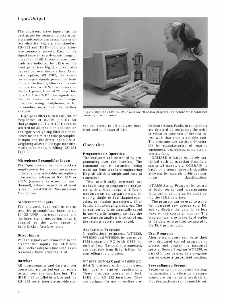
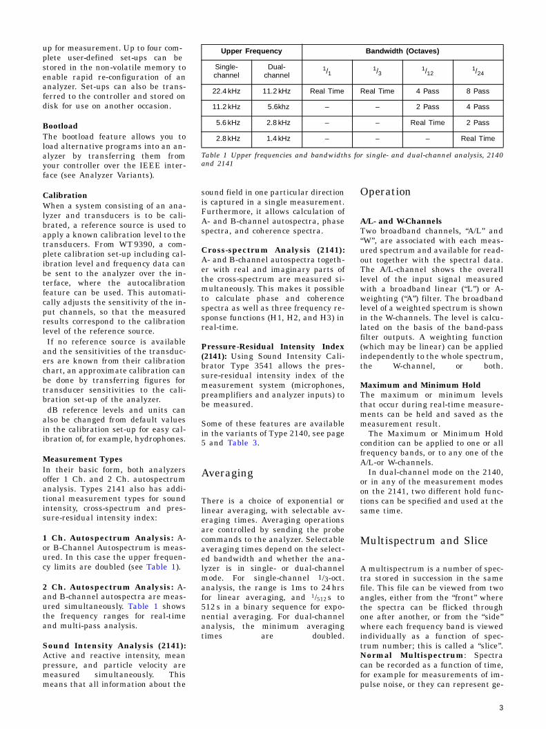
Fig.2 Using the 2140/WH 2857 with the QCMASK program to measure the mechanicalpower of a small motor
Input/Output
The analyzers have inputs on theback panel for connecting accelerom-eters, microphone preamplifiers or di-rect electrical signals, and standardRS–232 and IEEE–488 digital inter-face connector sockets. Each of thesignal inputs has a dynamic range ofmore than 80 dB. Instantaneous over-loads are indicated by LEDs on thefront panel (see Fig.1) and can alsobe read out over the interface. As anextra option, WH 2702, the condi-tioned input signals present in frontof the anti-aliasing filters can be out-put via the two BNC connectors onthe back panel, labelled “Analog Out-puts Ch.A & Ch.B”. The signals canthen be viewed on an oscilloscope,monitored using headphones, or fedto another instrument for furtheranalysis.
High-pass filters with 0.1 dB cut-offfrequencies of 0.7 Hz (0.35 Hz forcharge input), 20 Hz or 100 Hz can beselected for all inputs. In addition, ananalogue A-weighting filter can be se-lected for the microphone preamplifi-er input and the direct input. Pre-A-weighting allows SLM type measure-ments to be made, fulfilling IEC 651Type 0.
Microphone Preamplifier InputsThe 7-pin preamplifier input socketssupply power for microphone pream-plifiers, and a selectable microphonepolarization voltage of 0 V, 28 V or200 V (separate selection for eachchannel), allows connection of mosttypes of Brüel & Kjær MeasurementMicrophone.
Accelerometer InputsThe analyzers have built-in chargesensitive preamplifiers. Input is via10–32 UNF micro-connectors andthe input signal measuring range isadapted to the wide range ofBrüel & Kjær Accelerometers.
Direct InputsVoltage signals are connected to thepreamplifier inputs via LEMO-to-BNC socket adaptors (included as ac-cessories). Input coupling is AC.
InterfaceAll measurements and data transferoperations are carried out by remotecontrol over the interface bus. TheIEEE–488 parallel interface and theRS–232 serial interface provide con-
2
venient access to all analyzer func-tions and to measured data.
Operation
Programmable OperationThe analyzers are controlled by pro-gramming over the interface. Thecommand set is extensive, beingmade up from standard engineeringEnglish which is simple and easy toremember. This user-friendly command setmakes it easy to program the analyz-ers with a wide range of differentmeasurement set-up parameters, in-cluding: single- or dual-channel oper-ation, calibration parameters, filterbandwidth, averaging mode, etc. Thecurrent set-up is automatically savedin non-volatile memory, so that thenext time an analyzer is switched on,the settings remain unchanged.
Applications Programs3 applications programs, WT 9338,WT 9390 and WT 9550, for use on anIBM-compatible PC (with GPIB in-terface from National Instruments),are available from Brüel & Kjær forcontrolling the analyzers.
WT 9338 QCMASK and WT 9550 QC-BRAIN: are used with the analyzersfor quality control applications.These programs operate with bothIEEE and RS–232 interfaces. Theyare designed for use in on-line pro-
duction testing. Faults in the productare detected by comparing the noiseor vibration spectrum of the test ob-ject with that from a reliable unit.The programs are particularly suita-ble for manufacturers of rotatingequipment, e.g. pumps, compressors,motors, fans.
QCMASK is based on purely sta-tistical such as gaussian classifiers,statistical marks, etc. QCBRAIN isbased on a neural network classifierallowing, for example, arbitrary non-linear classifications.
WT 9390 Set-up Program: for controlof basic set-up and measurementfunctions in an interactive mode us-ing the IEEE interface.
The program can be used to trans-fer measured raw spectra to a PC,and to display the data in variousways on the computer monitor. Theprogram can also make hard copiesof the data on a printer connected tothe PC’s printer port.
User ProgramsAlternatively, users can write theirown dedicated control programs toprocess and display the measuredspectra. Set-up Program WT 9390, orpart of it, can be used by a program-mer to create a customised solution.
Pre-configured Set-upsFactory-programmed default settingsfor acoustics and vibration measure-ments are permanently available sothat the analyzers can be quickly set-
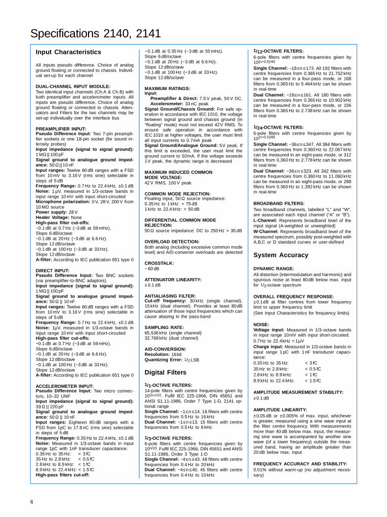
Upper Frequency Bandwidth (Octaves)
Single-channel
Dual-channel
1/11/3
1/121/24
22.4 kHz 11.2 kHz Real Time Real Time 4 Pass 8 Pass
11.2 kHz 5.6khz – – 2 Pass 4 Pass
5.6 kHz 2.8 kHz – – Real Time 2 Pass
2.8 kHz 1.4 kHz – – – Real Time
Table 1 Upper frequencies and bandwidths for single- and dual-channel analysis, 2140and 2141
up for measurement. Up to four com-plete user-defined set-ups can bestored in the non-volatile memory toenable rapid re-configuration of ananalyzer. Set-ups can also be trans-ferred to the controller and stored ondisk for use on another occasion.
BootloadThe bootload feature allows you toload alternative programs into an an-alyzer by transferring them fromyour controller over the IEEE inter-face (see Analyzer Variants).
CalibrationWhen a system consisting of an ana-lyzer and transducers is to be cali-brated, a reference source is used toapply a known calibration level to thetransducers. From WT 9390, a com-plete calibration set-up including cal-ibration level and frequency data canbe sent to the analyzer over the in-terface, where the autocalibrationfeature can be used. This automati-cally adjusts the sensitivity of the in-put channels, so that the measuredresults correspond to the calibrationlevel of the reference source. If no reference source is availableand the sensitivities of the transduc-ers are known from their calibrationchart, an approximate calibration canbe done by transferring figures fortransducer sensitivities to the cali-bration set-up of the analyzer. dB reference levels and units canalso be changed from default valuesin the calibration set-up for easy cal-ibration of, for example, hydrophones.
Measurement TypesIn their basic form, both analyzersoffer 1 Ch. and 2 Ch. autospectrumanalysis. Types 2141 also has addi-tional measurement types for soundintensity, cross-spectrum and pres-sure-residual intensity index:
1 Ch. Autospectrum Analysis: A-or B-Channel Autospectrum is meas-ured. In this case the upper frequen-cy limits are doubled (see Table 1).
2 Ch. Autospectrum Analysis: A-and B-channel autospectra are meas-ured simultaneously. Table 1 showsthe frequency ranges for real-timeand multi-pass analysis.
Sound Intensity Analysis (2141):Active and reactive intensity, meanpressure, and particle velocity aremeasured simultaneously. Thismeans that all information about the
sound field in one particular directionis captured in a single measurement.Furthermore, it allows calculation ofA- and B-channel autospectra, phasespectra, and coherence spectra.
Cross-spectrum Analysis (2141):A- and B-channel autospectra togeth-er with real and imaginary parts ofthe cross-spectrum are measured si-multaneously. This makes it possibleto calculate phase and coherencespectra as well as three frequency re-sponse functions (H1, H2, and H3) inreal-time.
Pressure-Residual Intensity Index(2141): Using Sound Intensity Cali-brator Type 3541 allows the pres-sure-residual intensity index of themeasurement system (microphones,preamplifiers and analyzer inputs) tobe measured.
Some of these features are availablein the variants of Type 2140, see page5 and Table 3.
Averaging
There is a choice of exponential orlinear averaging, with selectable av-eraging times. Averaging operationsare controlled by sending the probecommands to the analyzer. Selectableaveraging times depend on the select-ed bandwidth and whether the ana-lyzer is in single- or dual-channelmode. For single-channel 1/3-oct.analysis, the range is 1ms to 24 hrsfor linear averaging, and 1/512 s to512 s in a binary sequence for expo-nential averaging. For dual-channelanalysis, the minimum averagingtimes are doubled.
Operation
A/L- and W-ChannelsTwo broadband channels, “A/L” and“W”, are associated with each meas-ured spectrum and available for read-out together with the spectral data.The A/L-channel shows the overalllevel of the input signal measuredwith a broadband linear (“L”) or A-weighting (“A”) filter. The broadbandlevel of a weighted spectrum is shownin the W-channels. The level is calcu-lated on the basis of the band-passfilter outputs. A weighting function(which may be linear) can be appliedindependently to the whole spectrum,the W-channel, or both.
Maximum and Minimum HoldThe maximum or minimum levelsthat occur during real-time measure-ments can be held and saved as themeasurement result.
The Maximum or Minimum Holdcondition can be applied to one or allfrequency bands, or to any one of theA/L-or W-channels.
In dual-channel mode on the 2140,or in any of the measurement modeson the 2141, two different hold func-tions can be specified and used at thesame time.
Multispectrum and Slice
A multispectrum is a number of spec-tra stored in succession in the samefile. This file can be viewed from twoangles, either from the “front” wherethe spectra can be flicked throughone after another, or from the “side”where each frequency band is viewedindividually as a function of spec-trum number; this is called a “slice”.Normal Multispectrum: Spectracan be recorded as a function of time,for example for measurements of im-pulse noise, or they can represent ge-
3

ometrical points when measuringsound power. The recording rate is upto 1000 spectra/second (single-chan-nel operation).Gated Multispectrum: Allows mul-tispectra from successive trigger cy-cles to be averaged into a singlemultispectrum. The number of aver-aged multispectra equals the numberof triggers.
Gated measurements are normallyused for measuring noise from rotat-ing machines or other repetitivenoise.
Fig.3 shows the gating principle inone trigger cycle. The “gate” opensafter a user-specified trigger delay(positive only) has elapsed. One spec-trum is measured while the gate isopen. As the gate closes, the spec-trum is saved in an accumulator. Theopen-close-save sequence is then re-peated for all spectra in the triggercycle forming one multispectrum.Matrix Multispectrum: MatrixMultispectrum allows the spectra ina multispectrum to be arranged in arow-column-direction system. Thisserves two purposes: one is to easethe overview of measurements, theother is to make sound intensity datacompatible with computer programsand Brüel & Kjær laboratory analyz-ers (for example Type 2133) so thatsound power determination and otherdata processing can be made.
Multispectrum TriggerThe following trigger conditions canbe applied to the start of averagingwhen collecting a multispectrum:Free Run: The measurement de-fined by the current set-up is contin-ually repeated after Averaging⟨Start⟩ is sent.Manual: This triggers a measure-ment as defined by the current set-up. This is often used for sound in-tensity measurements with MatrixMultispectrum.
Time: Measurement begins at a timespecified by the user. A fixed repeti-tion interval can be set where re-quired.Internal: Measurement begins whena specified trigger level is exceeded(positive-slope trigger) or fallen below(negative-slope trigger) in either aspecified frequency band or in one ofthe channels displaying the broad-band weighted or non-weighted spec-trum level. Internal triggering isallowed on several spectrum types,for example intensity spectra orcross-spectra. Internal triggering isused, for example, for pistol-shot re-verberation measurements.External: Measurement begins onthe arrival of an external trigger sig-nal at the Trigger Input socket on theback panel of the analyzer. This isoften used for tacho-probe input withGated Multispectrum, or for run-up/coast-down measurements withNormal Multispectrum.
Pre- and Post-trigger DelayThe user-defined post-trigger delay (0to 5000 s depending on set-up) can beused to delay the start of averagingfor a fixed period after the triggerconditions have been met. Alterna-tively, entering negative values forthe post-trigger delay results in apre-trigger delay. Pre-trigger delayenables spectra monitored prior tothe trigger conditions being met to beincluded as part of the measurementresult. The maximum pre-trigger de-lay is 34 spectra for 1/3-octave meas-urements.
Data Storage
Spectrum MemoryThe spectrum memory is part of thememory allocated for storage ofmeasured data. The number of spec-tra that the spectrum memory canhold depends on the selected filterbandwidth, frequency range and themeasurement type, single channel,dual channel or sound intensity(sound intensity for Type 2141 only).
Table 2 shows the number of spec-tra that the memory can hold, meas-ured with the maximum real-timefrequency range (upper freq. limit22.4 kHz in single-channel mode and11.2 kHz in dual-channel mode for1/1-octave and 1/3-octave spectra).
Spectra are saved individually oras multispectra in up to 111 files.Note, however, that for multispectra
the maximum number of spectrawhich can be saved in one file is 999.
Disk StorageIf more data storage capacity is need-ed, files stored in spectrum memorycan be transferred over the interfaceto the controller, in binary or ASCIIformat, and stored on disk.
Spectrum Recording RateThe analyzers can record spectra atintervals down to 1 ms with no lossof data (no “gaps” between measure-ments). This maximum rate is ob-tained with single-channel, real-timeoperation. In general, the recordingrate depends on the chosen measure-ment type (single/dual-channel anal-ysis), filter bandwidth, frequencyrange and, if linear averaging hasbeen selected, the linear averagingtime.
Measurement TextEach file can be labelled with up to40 characters of text. Files can besorted in the file list, by name(number), time, length, or type.“Type” classifies the spectra/timerecords into groups according to:number of lines, measurement type,whether they were measured or cal-culated, and whether they are singlespectra or multispectra.
Multichannel Analysis System
In the example illustrated in Fig.4,eight Type 2140 units and a commonpower supply, WB 1250, make up asystem for measurement of spectra in16 input channels simultaneously.
The system shown takes up an in-stallation height of 177.8 mm per row,or in total 533.4 mm. The WB 1250power supply is capable of supplyingup to 15 analyzers (30 input chan-nels). Several analyzers, of the sameor different types, can be configuredas a multichannel system for analysisof signals from multiple transducers(e.g. accelerometers and/ or micro-phones) at various measuring pointsaround (on) the test object. In thisway very descriptive measurementresults can be obtained over time (e.g.a monitoring system) or for severaldifferent test objects (e.g. test-cellmeasurements). For the analysis oftransient events, each analyzer may
Fig.3 Gated measurement cycle
Trigger
900204/2e
Trigger Delay(positive only)
GatingWidth
DataCollection
1
2
3
4

Bandwidth
Type 2140 Type 2141
Single channel
Dual Channel
Single channel
Dual Channel
Sound Intensity
1/1-octave 2457 1843 2457 1843 1203
1/3-octave 1474 951 1474 951 541
1/12-octave 589 340 589 340 178
1/24-octave 342 193 342 193 99
Table 2 Storage capacity for real-time spectra
Modification No.
Analyzer Features Mode Comments
Dual-channel autospectrum DF➀ Standard 2140 Analyzer
WH 2855 Dual-channel autospectrum (to 20kHz) DF
Standard 2140 with dual-channel analysis extended to 20kHz
WH 2857 Full dual channel with cross functions (not intensity) DF
Standard 2140 with mechanical power measurement option
WH 2859 Dual-channel FFT with cross functions FFT
FFT analysis instead of digital filtering
WH 2960Single-channel autospectrum (to 20 kHz) DF
Standard 2140 for single-channel measurements
WH 2990 Single-channel autospectrum FFT FFT equivalent of WH 2960
➀ Digital filtering
Table 3 Analyzer variants
be set up to measure a triggered mul-tispectrum, in which case all sub-spectra of the individual multispectrawill be time coincident.
Post-Processing
The analyzers are mainly intended asdata gathering devices. However,they also have some data processingfacilities. Some of these facilitiesfunction in real-time and some canbe applied to recalled spectra.
Spectrum UnitThe spectrum unit is PWR (power) orRMS (root mean square), dependingon the type of measurement.
Sound Power CalculationSound power can be calculated on thebasis of SPL or intensity measure-ments. Data must be arranged in amultispectrum. The calculation ismade by entering the physical size ofthe enclosing area.
Spectrum ArithmeticThe Spectrum Calculator is used forarithmetic operations on spectra re-called from memory.
The arithmetic basis for spectrumadditions and subtractions can be se-lected as either “dB” (for which 50 dB
Fig.4 Rack-installed 2140 Analyzer Sys-tem powered by WB 1250
plus 50 dB equals 100 dB) or as “ab-solute power”, for which dB units arefirst converted to absolute powerunits for the arithmetic operationand then converted back to dB for thefinal answer (50 dB plus 50 dB equals53 dB).
“dB” arithmetic is used for add-ing/subtracting single number con-stants or weighting corrections to/from spectra. “Absolute power” arith-metic is for adding and subtractingspectra or background noise spectra.
Digital Spectrum WeightingSpectrum Weighting is used to adduser-defined weightings or standardA-, B-, C-, and D-weightings to inputspectra (real-time) or to spectra re-called from the memory. Spacer (S)and Spacer + A (SA) weightings arealso available for intensity spectra.The shape of these weightings is de-
pendent on the nominal microphonespacing of the sound intensity probe.User-defined weightings are enteredas a series of points, with the analyz-er interpolating between the pointsto produce the complete weightingfunction, or they can be based onmeasured data. A total of four user-defined weightings can be saved inthe non-volatile internal memory.User-defined weightings can be used,for example, to mask unwanted fre-quency components.
Analyzer Variants
A number of variants of the standard2140 Analyzer are available. Theseare described briefly in Table 3.Please contact Brüel & Kjær if youwould like more information.
5
Specifications 2140, 2141
Input CharacteristicsAll inputs pseudo difference. Choice of analogground floating or connected to chassis. Individ-ual set-up for each channel
DUAL-CHANNEL INPUT MODULE:Two identical input channels (Ch.A & Ch.B) withboth preamplifier and accelerometer inputs. Allinputs are pseudo difference. Choice of analogground floating or connected to chassis. Atten-uators and Filters for the two channels may beset-up individually over the interface bus
PREAMPLIFIER INPUT:Pseudo Difference Input: Two 7-pin preampli-fier sockets or one 18-pin socket (for sound in-tensity probes)Input impedance (signal to signal ground):1 MΩ || 100 pFSignal ground to analogue ground imped-ance: 50 Ω || 10 nFInput ranges: Twelve 80 dB ranges with a FSDfrom 10 mV to 3.16 V (rms sine) selectable insteps of 5 dBFrequency Range: 0.7 Hz to 22.4 kHz, ±0.1 dBNoise: 1 µV, measured in 1/3-octave bands ininput range 10 mV with input short-circuitedMicrophone polarization: 0 V, 28 V, 200 V from10 MΩ sourcePower supply: 28 VHeater Voltage: NoneHigh-pass filter cut-offs:−0.1 dB at 0.7 Hz (−3 dB at 59 mHz).Slope 6 dB/octave−0.1 dB at 20 Hz (−3 dB at 6.6 Hz).Slope 12 dB/octave−0.1 dB at 100 Hz (−3 dB at 33 Hz).Slope 12 dB/octaveA-filter: According to IEC publication 651 type 0
DIRECT INPUT:Pseudo Difference Input: Two BNC sockets(via preamplifier-to-BNC adaptors)Input impedance (signal to signal ground):1 MΩ || 100 pFSignal ground to analogue ground imped-ance: 50 Ω || 10 nFInput ranges: Twelve 80 dB ranges with a FSDfrom 10 mV to 3.16 V (rms sine) selectable insteps of 5 dBFrequency Range: 0.7 Hz to 22.4 kHz, ±0.1 dBNoise: 1µV, measured in 1/3-octave bands ininput range 10 mV with input short-circuitedHigh-pass filter cut-offs:−0.1 dB at 0.7 Hz (−3 dB at 59 mHz).Slope 6 dB/octave−0.1 dB at 20 Hz (−3 dB at 6.6 Hz).Slope 12 dB/octave−0.1 dB at 100 Hz (−3 dB at 33 Hz).Slope 12 dB/octaveA-filter: According to IEC publication 651 type 0
ACCELEROMETER INPUT:Pseudo Difference Input: Two micro connec-tors, 10–32 UNFInput impedance (signal to signal ground):39 Ω || 220 pFSignal ground to analogue ground imped-ance: 50 Ω || 10 nFInput ranges: Eighteen 80 dB ranges with aFSD from 1pC to 17.8 nC (rms sine) selectablein steps of 5 dBFrequency Range: 0.35 Hz to 22.4 kHz, ±0.1 dBNoise: Measured in 1/3-octave bands in inputrange 1pC with 1nF transducer capacitance:0.35 Hz to 35 Hz: < 3 fC35 Hz to 2.8 kHz: < 0.5 fC2.8 kHz to 8.9 kHz: < 1 fC8.9 kHz to 22.4 kHz: < 1.5 fCHigh-pass filters cut-off:
−0.1 dB at 0.35 Hz (−3 dB at 50 mHz).Slope 6 dB/octave−0.1 dB at 20 Hz (−3 dB at 6.6 Hz).Slope 12 dB/octave−0.1 dB at 100 Hz (−3 dB at 33 Hz).Slope 12 dB/octave
MAXIMUM RATINGS:Input:
Preamplifier & Direct: 7.5 V peak, 50 V DC.Accelerometer: 33 nC peak
Signal Ground/Chassis Ground: For safe op-eration in accordance with IEC 1010, the voltagebetween signal ground and chassis ground (in“floating” mode) must not exceed 42V RMS. Toensure safe operation in accordance withIEC 1010 at higher voltages, the user must limitall input currents to 0.7mA peakSignal Ground/Analogue Ground: 5V peak. Ifthis limit is exceeded, the user must limit theground current to 50mA. If the voltage exceeds1V peak, the dynamic range is decreased
MAXIMUM INDUCED COMMONMODE VOLTAGE:42 V RMS, 100 V peak
COMMON MODE REJECTION:Floating input, 50 Ω source impedance:0.35 Hz to 1 kHz: > 75 dB1 kHz to 22.4 kHz: > 50 dB
DIFFERENTIAL COMMON MODE REJECTION:50 Ω source impedance: DC to 250 Hz > 35 dB
OVERLOAD DETECTION:Both analog (including excessive common modelevel) and A/D-converter overloads are detected
CROSSTALK:− 60 dB
ATTENUATOR LINEARITY:± 0.1 dB
ANTIALIASING FILTER:Cut-off frequency: 30 kHz (single channel),15 kHz (dual channel). Provides at least 80dBattenuation of those input frequencies which cancause aliasing in the pass-band
SAMPLING RATE:65.536 kHz (single channel)32.768 kHz (dual channel)
A/D-CONVERSION:Resolution: 16bitQuantizing Error: 1/2 LSB
Digital Filters
1/1-OCTAVE FILTERS:14-pole filters with centre frequencies given by103xn/10. Fulfil IEC 225-1966, DIN 45651 andANSI S1.11-1986, Order 7 Type 1-D, 2141 op-tional rangeSingle Channel: −1≤n ≤14. 16 filters with centrefrequencies from 0.5 Hz to 16 kHzDual Channel: −1≤n ≤13. 15 filters with centrefrequencies from 0.5 Hz to 8 kHz
1/3-OCTAVE FILTERS:6-pole filters with centre frequencies given by10n/10. Fulfil IEC 225-1966, DIN 45651 and ANSIS1.11-1986, Order 3 Type 1-DSingle Channel: −4≤n ≤43. 48 filters with centrefrequencies from 0.4 Hz to 20 kHzDual Channel: −4≤n ≤40. 45 filters with centrefrequencies from 0.4 Hz to 10 kHz
1/12-OCTAVE FILTERS:6-pole filters with centre frequencies given by10(n+0.5)/40
Single Channel: –18≤n ≤173. All 192 filters withcentre frequencies from 0.365 Hz to 21.752 kHzcan be measured in a four-pass mode, or 168filters from 0.365 Hz to 5.464 kHz can be shownin real-timeDual Channel: −18≤n ≤161. All 180 filters withcentre frequencies from 0.365 Hz to 10.902 kHzcan be measured in a four-pass mode, or 156filters from 0.365 Hz to 2.738 kHz can be shownin real-time
1/24-OCTAVE FILTERS:6-pole filters with centre frequencies given by10(n+0.5)/80
Single Channel: −36≤n ≤347. All 384 filters withcentre frequencies from 0.360 Hz to 22.067 kHzcan be measured in an eight-pass mode, or 312filters from 0.360 Hz to 2.778 kHz can be shownin real-timeDual Channel: −36≤n ≤323. All 342 filters withcentre frequencies from 0.360 Hz to 11.060 kHzcan be measured in an eight-pass mode, or 288filters from 0.360 Hz to 1.392 kHz can be shownin real-time
BROADBAND FILTERS:Two broadband channels, labelled “L” and “W”,are associated each input channel (“A” or “B”).L-Channel: Represents broadband level of theinput signal (A-weighted or unweighted)W-Channel: Represents broadband level of themeasured spectrum, possibly post-weighted withA,B,C or D standard curves or user-defined
System Accuracy
DYNAMIC RANGE:All distortion (intermodulation and harmonic) andspurious noise at least 80dB below max. inputfor 1/3-octave spectrum
OVERALL FREQUENCY RESPONSE:±0.1dB at filter centres from lower frequencylimit to upper frequency limit(See Input Characteristics for frequency limits)
NOISE:Voltage input: Measured in 1/3-octave bandsin input range 10mV with input short-circuited:0.7Hz to 22.4kHz < 1µVCharge input: Measured in 1/3-octave bands ininput range 1 pC with 1 nF transducer capaci-tance:0.35 Hz to 35 Hz: < 3 fC35 Hz to 2.8 kHz: < 0.5 fC2.8 kHz to 8.9 kHz: < 1 fC8.9 kHz to 22.4 kHz: < 1.5 fC
AMPLITUDE MEASUREMENT STABILITY:±0.1 dB
AMPLITUDE LINEARITY:±0.05 dB or ±0.005% of max. input, whicheveris greater, measured using a sine wave input atthe filter centre frequency. With measurementsmore than 40 dB below max. input, the measur-ing sine wave is accompanied by another sinewave (of a lower frequency) outside the meas-ured band, having an amplitude greater than20 dB below max. input
FREQUENCY ACCURACY AND STABILITY:0.01% without warm-up (no adjustment neces-sary)
6
COMPLIANCE WITH STANDARDS:
CE-mark indicates compliance with: EMC Directive and Low Voltage Directive.
Safety EN 61010–1 and IEC 1010–1: Safety requirements for electrical equipment for measurement, control and laboratory use.
EMC Emission EN 50081–1: Generic emission standard. Residential, commercial and light industry.EN 50081–2: Generic emission standard. Industrial environment.CISPR 22: Radio disturbance characteristics of information technology equipment. Class B Limits.FCC Rules, Part 15: Complies with the limits for a Class B digital device.
EMC Immunity EN 50082–1: Generic immunity standard. Residential, commercial and light industry.EN 50082–2: Generic immunity standard. Industrial environment. Note: See “EMC”.
Temperature IEC 68–2–1 & IEC 68–2–2: Environmental Testing. Cold and Dry Heat.Operating Temperature: –10 to +55°C (+14 to +131°F)Storage Temperature: –25 to +70°C (–13 to +158°F)
Humidity IEC 68–2–3: Damp Heat: 90% RH (non-condensing at 40°C (104°F))
Mechanical Non-operating:IEC 68–2–6: Vibration: 0.3 mm, 20 m/s2, 10–500 HzIEC 68–2–27: Shock: 1000 m/s2
IEC 68–2–29: Bump: 1000 bumps at 250 m/s2
Enclosure IEC 529: Protection provided by enclosures: IP 20
Detectors
Digital true RMS detection of filter bank and twobroadband channels. No crest factor limitation
UPPER FREQUENCY LIMIT FOR ANALYSIS:11.2 kHz for dual-channel autospectra. (Ch.A +Ch.B)22.4 kHz for single-channel autospectrum. (Ch.Aor Ch. B)
CONTROL:Note: All control must be exercised over the in-terface busStart: Clears the average accumulator andstarts an averageStop: Stops the averaging processProceed: Continues an average without clearingthe average accumulatorAveraging gate: External or internal trigger sig-nal for gating the averaging process
Averaging
LINEAR:Averaging without truncationSingle Channel: Averaging times from 1ms to24 hours selectable to a resolution of 1ms in therange 1ms to 1 hour and to 1s in the range 1hour to 24 hoursDual Channel: Averaging times from 2ms to 24hours selectable to a resolution of 1ms in therange 2ms to 1 hour and to 1s in the range1 hour to 24 hours
EXPONENTIAL:Single Channel: 19 averaging times from1/512s to 512s in a binary sequenceDual Channel: 18 averaging times from 1/256sto 512s in a binary sequenceAveraging times of 1/4s and 2s correspond to“Fast” and “Slow” sound level meter responses,respectively
Spectrum Memory
Non-volatile internal memory in which a maxi-mum of 111 files, each containing a single spec-trum or a multispectrum, can be stored.Control: Manual save (controlled from compu-ter) or multispectrum automatic saveMax. no. of spectra: 1843 for a dual-channel1/1 oct. measurementMax. (or Min.) hold, all bands: Compositespectrum of max. (or min.) RMS level occurringin each channelMax. (or Min.) hold, specified band: Retainsthe spectrum for which max. (or min.) RMS levelhas occurred in the specified band
Interfaces
NB! All control, set-up and data transfer musttake place over the Interface Bus
IEC/IEEE INTERFACE:Conforms to IEEE 488.1 and IEC 625-1 stand-ards.Functions Implemented:Source Handshake SH1Acceptor Handshake AH1Talker T5Listener L3Service Request SR1Parallel Poll PP1Device Clear DC1Device Trigger DT1Remote/Local RL0Command Set: Simple and easy to rememberstandard engineering English. Resistant to op-erator errorCode: ASCII (ISO 7-bit) code, or binary
Interface Terminator: Default is ASCII <LF>,(decimal 10)Device Address: Specified via back panel Ad-dress Switch
RS-232 INTERFACE:Conforms to the EIA Standard RS-232-C (equiv-alent to CCITT V24)Allows remote activation of the analyzer func-tions via a non-intelligent terminal
Controls/Indicators
FRONT PANEL:LED Indicators: Show if the analyzer isswitched on, Self-test, Interface and Overloadstatus, and whether Ch.A and Ch.B are protect-ed. (Protect relays break the signal path, if theAnalog Input Module is exposed to excessivesignal levels).Reset: Used to reset the analyzer manuallyPower Switch: Switches the analyzer On andOff.Master Reset: Returns the analyzer to factorydefault settings
BACK PANEL:Polarization Voltage A&B: Selects a micro-phone polarization voltage of 0, 28, or 200V foreach input, as specified on the microphone cal-ibration chartAuxiliary C onnector: Reserved for future useInterface IEEE–488: 24-pole male socket forremote control of the analyzer and for digitaloutput of measurement results via the IEEE–488parallel interfaceInterface RS–232: 24-pole male socket for re-mote control of the analyzer and for digital outputof measurement results via the RS–232 serialinterfaceAddress Switches: 8 external and 4 internalDIP switches, the settings of which determinethe active interface, the Device Address(IEEE–488), and some RS–232 parameters.The remaining RS–232 parameters are selecta-ble using the internal switchesApplications: 7-pin LEMO socket, reserved forfuture use
Analog Output Ch.A, Ch.B: Used only if en-hancement WH 2702 has been fitted. BNC con-nectors for Ch.A and Ch.B, outputting theconditioned signals present in front of the an-tialiasing filters for the two channels.Ext. Power: 7-pin DIN socket for connection ofan external power supplyFuse 5A: Fuse holder containing a T5A fuseExt. Trigger: Triaxial BNT connector for input ofan external trigger signal to start an average.5 V available from the connectors inner screenfor powering of an external trigger source. (e.g.a photoelectric tachometer probe)Preamplifier A&B: Two 7-pin connectors forconnecting microphone to the internal preampli-fiersCharge A&B: Two TNC connectors for connect-ing accelerometers to the built-in, charge-sensi-tive amplifiersChassis/Floating: Connects/disconnects ana-log ground to/from the analyzer chassisSound Intensity/Remote Control: 18 pin Lemofor use with Sound Intensity Probe Type 3548
Power Supply
The 2140 Analyzer must be powered from anexternal source via the “Ext. Power” socket (7-pin DIN socket). The source must be capable ofdelivering a filtered DC Voltage in the range 11 Vto 16 VPower consumption: Approx. 8.5 W
EMC
SUSCEPTIBILITY TO DISTURBANCES SPECIFIED IN EN 50082–2:LF Magnetic Field: (30 A/m at 50 Hz)
1 Input section with max. gain and input short-circuited2 Input section with max. gain and 1 nF termination
Input/Output Level
Preamp., ProbeDirect via Preamp.1
< 10 µV
Charge2 < 1 fC
7

B
Radiated RF: (3 to 10 V/m, 80% AM, 1 kHz)
1 Input section with max. gain and input short-circuited2 Input section with max. gain and 1 nF termination
Conducted RF: (3 to 10 V, 80% AM, 1 kHz) Cabinet
The 2140 Analyzer is supplied in a lightweightmetal cabinet. 3 x 2140 units can be installedside-by-side in a standard 19″ rack, thus allowingfor the build-up of very compact multi-channelanalyzer systems. The 3 analyzers take up aninstallation height of 4 standard rack-mountingheight units ≥177.8 mm
DIMENSIONS: (without feet)Height: 177 mm (7.0″)Width: 142.5 mm (5.6″)Depth: 320 mm (12.6″)Weight: 5.5 kg (12lb. 3oz.)
Input/Output Level
Preamp., ProbeDirect via Preamp.1
< 30 µV
Charge2 < 32 fC
Input/Output Level
Preamp., ProbeDirect via Preamp.1
< 1 µV
Charge2 < 5 fC
rüel & Kjær B K
BP1316 – 13 95/12
WORLD HEADQUARTERS: DK-2850 Nærum • Denmark • Telephone: +4542800500 •Telex: 37316 bruka dk • Fax: +4542801405 • e-mail: [email protected]
Ordering InformationAccessories IncludedTypes 2140 and 2141 Bus-Controlled FrequencyAnalyzersInclude the following accessories:JP 0710: 7-pin DIN plug (for Ext. Power
socket)2 × AO 0479: Falcon (LEMO)-to-BNC Adaptor5 × VF 0015: 5 A fusesWL 0845: Short Interface Cable (0.4 m),
IEEE–488 (multichannel systems only)
Type 7667: 31/2″ disk containing the analyzer program
Optional Accessories
POWER SUPPLYWB 1250: 12 V power supply for multiple
2140 & 2141 units
TRANSDUCERSType 4190: General-purpose 1/2″ Measuring
MicrophoneType 2669: Microphone PreamplifierType 4371: General-purpose AccelerometerJP 0162: Adaptor for Type 4371AO 0488: 7-pin B&K (preamp.) to LEMO
AdaptorBrüel & Kjær supplies a wide range of micro-phones and accelerometers. Please ask for
more information regarding the different typesand their uses
CALIBRATIONType 4226: Multifunction Acoustic CalibratorType 4228: PistonphoneType 4231: Sound Level CalibratorType 4294: Calibrator ExciterType 3541: Sound Intensity Calibrator
INTERFACEAO 0195: Adaptor to convert IEEE–488
connector to IEC 625-1 (25-way)AO 0264: Interface Cable (2m), IEC 625-1
(25-way) to IEEE–488AO 0265: Interface Cable (2m), IEEE–488 to
IEEE–488UA 0814: IEEE–488 24-way bus connector
kitWB 1264: Production Controller InterfaceWL 0945: Null-modem Cable for RS–232
(1.5m, 25-pin female to 9-pin male)
WL 0946: Null-modem Cable for RS–232 (1.5m, 25-pin female to 25-pin female)
WL 0947: Null-modem Cable for RS–232 (1.5m, 25-pin female to 25-pin male)
PLC controller
HARDWARE ENHANCEMENTWH 2702: Analog Output Modification
ANALYZER VARIANTSBrüel & Kjær supplies a number of variants of thebasic Type 2140 Analyzer. Please ask for moreinformation regarding the different types andtheir uses.WH 2855: Dual-channel digital filtering (DF),
two autospectra up to 20kHzWH 2857: Dual-channel DF, autospectra,
cross-spectra (plus mechanical power measurements)
WH 2859: Dual-channel FFT with cross functions
WH 3129: SIngle-channel CPBWH 3130: Single-channel FFT
ANALYZER UPGRADEWH 2858: Upgrade from Type 2140 to Type
2141
COMPUTER SOFTWAREFor use with an IBM-compatible PCWT 9338: QCMASKWT 9390: Set-up ProgramWT 9550: QCBRAINType 7680: Sound Power program, pressure
basedType 7681: Noise Source Location program
Brüel&Kjær reserves the right to change specifications and accessories without notice