Product Data · 2019-08-20 · FX4D Comfort Series Fan Coil Sizes 019 thru 061 Product Data A10009...
16
FX4D Comfort Series Fan Coil Sizes 019 thru 061 Product Data A10009 AIR HANDLER TECHNOLOGY AT ITS FINEST The FX4D fan coils combine the proven technology of Carrier fan coil units with Puron®, the environmentally sound refrigerant. These fan coils are loaded with popular features. Factory−installed, refrigerant−specific thermostatic expansion valves (TXV) are standard with these fan coil designs. The designs feature contoured condensate pans with rugged, drain connections, ensuring that little water is left in the unit at the end of the cooling duty cycle. The lack of standing condensate and corrosion free pans improves IAQ and product life, features homeowners appreciate. Standard features include grooved tubing and louvered aluminum fins. The large face areas of the refrigerant coils provide superior efficiency for high SEER and HSPF performance. Coil circuiting has also been updated to make the most of all Carrier heat pumps and air conditioners. Also units come with solid state fan controls, 1−in (25mm) thick insulation with R−value of 4.2, multi−speed motors, and fully−wettable coils. Units can accommodate factory− and/or field−installed heaters from 3 to 30 kW. Assembled at the factory compliant with low leak requirements of less than 2% cabinet leakage rate at 0.5 inches W.C. and 1.4% cabinet leakage rate at 0.5 inches W.C. when tested in accordance with ASHRAE 193 standard. The FX4D fan coil is the Puron® refrigeration design loaded with popular features. It comes in a pre−painted (taupe metallic) galvanized steel casing and is shipped with a cleanable, permanent framed filter, and a factory−supplied power plug. These fan coils utilize the latest in electronic commutation motor (ECM) technology through the use of high efficiency, multi−tap ECM motors.
Transcript of Product Data · 2019-08-20 · FX4D Comfort Series Fan Coil Sizes 019 thru 061 Product Data A10009...

FX4DComfort Series Fan CoilSizes 019 thru 061
Product Data
A10009
AIR HANDLER TECHNOLOGYAT ITS FINEST
The FX4D fan coils combine the proven technology of Carrier fancoil units with Puron®, the environmentally sound refrigerant.These fan coils are loaded with popular features. Factory−installed,refrigerant−specific thermostatic expansion valves (TXV) arestandard with these fan coil designs. The designs feature contouredcondensate pans with rugged, drain connections, ensuring that littlewater is left in the unit at the end of the cooling duty cycle. Thelack of standing condensate and corrosion free pans improves IAQand product life, features homeowners appreciate.
Standard features include grooved tubing and louvered aluminumfins. The large face areas of the refrigerant coils provide superiorefficiency for high SEER and HSPF performance. Coil circuitinghas also been updated to make the most of all Carrier heat pumpsand air conditioners. Also units come with solid state fan controls,1−in (25mm) thick insulation with R−value of 4.2, multi−speedmotors, and fully−wettable coils. Units can accommodate factory−and/or field−installed heaters from 3 to 30 kW.
Assembled at the factory compliant with low leak requirements of less than 2% cabinet leakage rate at 0.5 inches W.C. and 1.4%cabinet leakage rate at 0.5 inches W.C. when tested in accordance with ASHRAE 193 standard.
The FX4D fan coil is the Puron® refrigeration design loaded withpopular features. It comes in a pre−painted (taupe metallic)galvanized steel casing and is shipped with a cleanable, permanentframed filter, and a factory−supplied power plug. These fan coilsutilize the latest in electronic commutation motor (ECM)technology through the use of high efficiency, multi−tap ECMmotors.
2
STANDARD FEATURES� Multi−tap ECM (electronic commutating motor) motors − all sizes� Integrated motor controls have replaced integrated circuit board� Large, grooved tube, louvered fin coils� Efficient, quiet, time−tested blower housings and diffusers� Sturdy, drainable condensate pans� Cabinet construction features innovations designed to prevent cabinet sweating� Tested for condensate disposal in much tougher conditions than Air Conditioning and Refrigeration Institute requirements� Super−thick R−4.2 insulation with vapor barrier� Pre−painted galvanized steel cabinet (taupe metallic)� Installation−flexible, multipoise units� Horizontal hanging provisions on cabinet� No tools required to service filter� Factory−supplied, cleanable and reusable filter� Newly improved filter rack area filter door insulation added for improved air seal� Factory−installed heater packages available (5− through 15−kW)� 3− through 30−kW accessory heaters − field installed� Factory−supplied power plug� Easy plug−in provisions for heater installation� Entry options for high and low voltage wiring hook−up� Simple, 5−amp blade fuse (and a spare) to protect 40 VA transformer� Leak−preventing sweat connections� Modular cabinets available on 031 through 061 sizes.� Designed for manufactured housing applications.� Puron®, environmentally sound refrigerant� Factory−installed Puron® refrigerant thermostatic expansion valves (TXV)� Factory−installed heater packages available

3
MODEL NUMBER NOMENCLATURE
CARRIER FAN COILS1 2 3 4 5 6 7 8 9 10 11 12F X 4 D N B 0 1 9 0 0 0
Product Type Heating SizeFan Coil, Multipoise with Puron 000 = No Heat
005 = 5kW
Electrical 008 = 8 kW
N − 208/230v, 1 ph, 60 Hz 010 = 10kW
015 = 15kW
Cabinet Style Coil TypeB − Modular 0 = CopperF − Single Piece T = Tin−plate
L = Aluminum
Capacity019 = 18,000
025 = 24,000
031 = 30,000
037 = 36,000
043 = 42,000
049 = 48,000
061 = 60,000
the environmentally sound refrigerant
Use of the AHRI CertifiedTM Mark indicates amanufacturer’s participation in the program For verification of certification for individual products, go to www.ahridirectory.org.

4
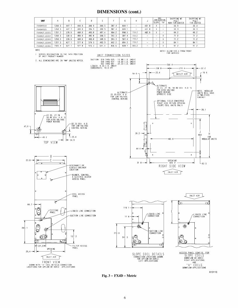
DIMENSIONS
NOTE: 1. SERIES DESIGNATION IS THE 14TH POSITION OF UNIT PRODUCT NUMBER 2. ALL DIMENSIONS ARE IN "INCHES" UNLESS NOTED.
NOTE: ALLOW 21" FROM FRONT FOR SERVICE
1 7/8"
1 3/8"1 15/16" 1"
TOP VIEW
7/8"DIA. K.O.FOR LOW VOLTAGECONTROL WIRING
7/8", 1 3/32"2" DIA. K.O.'SFOR HIGH VOLTAGEPOWER WIRING
6 3/16"
2 5/8"
10 7/16"
1"
15/16"
5"
D
BLOWER, CONTROL,& ELECTRIC HEATERACCESS PANEL
COIL ACCESSPANEL
DISCONNECT ORCIRCUIT BREAKERLOCATION
LIQUID LINE CONNECTION
SUCTION LINE CONNECTION
FILTER ACCESSPANEL
FITTINGPANEL
BC
FRONT VIEWSHOWN WITH "A" COIL DETAILS CONNECTION
LOCATIONS FOR UPFLOW OR HORIZ. APPLICATIONS
INLET AIR
OPENING
10 3/4"
3 1/16"
4 11/16"
E
9 1/2"
ACCESS PANEL CONFIG. FOR
SLOPE COILSDOWNFLOW OR HORIZ.RIGHT APPLICATIONS
AND
"A" COILSDOWNFLOW APPLICATIONS
LIQUID LINECONNECTION
LIQUID LINECONNECTION
SUCTION LINECONNECTION
SLOPE COIL DETAILSCONNECTION LOCATIONS SHOWN
FOR UPFLOW OR HORIZ.LEFT APPLICATIONS
INLET AIR
1 1/2"
2 1/2"
1"
10 3/16"
3/4"
22 1/16"
OPENING19 13/16"
2 1/8"
1 1/4"
A
FORMODULAR UNITS
1 3/16"
MAX
7/8"11"
1 3/4"
19"
NOTE: MODULARUNITS WILL HAVEA TWO-PIECECABINET
RIGHT SIDE VIEW
OPTIONAL FIELD CONVERTEDRIGHT SIDE RETURN OPENING(SLOPE COIL UNITS ONLY)
ALTERNATE7/8"DIA. K.O.
FOR LOW VOLTAGECONTROL WIRING
ALTERNATE7/8",1 3/32",2"DIA. K.O.'SFOR HIGH VOLTAGEPOWER WIRINGOPPOSITE SIDE
INLET AIR
OUTLET AIR
HJ
UNIT A B C D E F G H JCOIL
CONFIGURATIONSHIPPING WT
(LBS)NON TIN-COATED
SHIPPING WT(LBS)
TIN-COATEDSLOPE "A"
49 5/8" 17 5/8" 15 3/4" 15 5/8" 15 3/8" 23 1/8" 23 5/8" - 17" X - 122 122FX4DNF019
49 5/8" 17 5/8" 15 3/4" 15 5/8" 15 3/8" 23 1/8" 23 5/8" - 17" X - 122 122
53 7/16" 21 1/8" 19 1/4" 19 1/8" 19 3/16" 26 15/16" 27 1/2" 19" X - 146 146
49 5/8" 21 1/8" 19 1/4" 19 1/8" 15 11/16" 23 7/16" 23 1/8" - - X 157 157
49 5/8" 21 1/8" 19 1/4" 19 1/8" 15 11/16" 23 7/16" 23 1/8" - - - X 157 157
53 7/16" 24 11/16" 22 3/4" 22 11/16" 19 1/2" 27 1/4" 26 15/16" - - X 185 185
59 3/16" 24 11/16" 22 3/4" 22 11/16" 25 1/4" 32 15/16" 32 5/8" - - X 201 201
SUCTION: 018 THRU 025 - 5/8" I.D. SWEAT 030 THRU 037 - 3/4" I.D. SWEAT 042 THRU 061 - 7/8" I.D. SWEATLIQUID: 3/8" I.D. SWEATCONDENSATE: 3/4" FPT
UNIT CONNECTION SIZES
FX4DNF025
FX4DN(F,B)031
FX4DN(F,B)037
FX4DN(F,B)043
FX4DN(F,B)049
FX4DN(F,B)061
28 5/16”
28 5/16”
28 5/16”
28 5/16”
34 1/16”
A13112
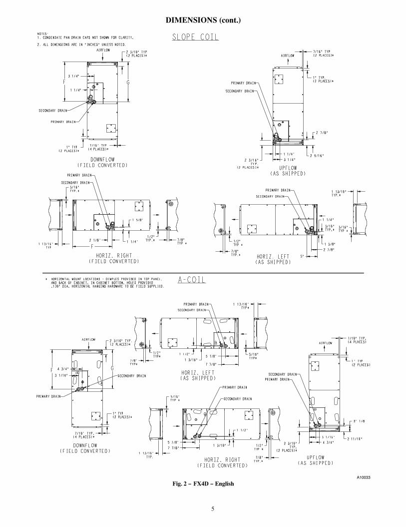
Fig. 1 − FX4D − English
5
DIMENSIONS (cont.)
A-COIL
NOTES:1. CONDENSATE PAN DRAIN CAPS NOT SHOWN FOR CLARITY. 2. ALL DIMENSIONS ARE IN "INCHES" UNLESS NOTED.
* HORIZONTAL MOUNT LOCATIONS - DIMPLES PROVIDED IN TOP PANEL, AND BACK OF CABINET. IN CABINET BOTTOM. HOLES PROVIDED
SLOPE COIL
3 1/4"2 9/16"
2 7/8"
2 3/16"TYP.
(2 PLACES)*
7/16" TYP.(2 PLACES)*
1" TYP.(2 PLACES)*
1 1/4"
AIRFLOW
SECONDARY DRAIN
PRIMARY DRAIN
UPFLOW(AS SHIPPED)
7/8"TYP.*
1/2"TYP.*2 1/8"
1 5/8"
F1 1/4"
PRIMARY DRAIN
SECONDARY DRAIN
HORIZ. RIGHT(FIELD CONVERTED)
1 1/4"
3 1/4"
1" TYP.(2 PLACES)*
7/16" TYP.(4 PLACES)*
2 3/16" TYP.(2 PLACES)*
GF
AIRFLOW
SECONDARY DRAIN
PRIMARY DRAIN
DOWNFLOW(FIELD CONVERTED)
1 13/16"TYP.*
5/16"TYP.*
1 5/8"
5/16"TYP.*
7/8"TYP.*
2 7/8"
5"
1 1/4"
1/2"TYP.*
SECONDARY DRAIN
PRIMARY DRAIN
HORIZ. LEFT(AS SHIPPED)
1 13/16"TYP.
5/16"TYP.*
1" TYP.(2 PLACES)*
7/16" TYP,(4 PLACES)*
4 3/4"
3 1/16"
F
2 3/16" TYP.(2 PLACES)*
G
AIRFLOW
DOWNFLOW(FIELD CONVERTED)
SECONDARY DRAIN
PRIMARY DRAIN
7 7/8"1 3/16"
1 1/2"
1/2"TYP.*
1 13/16"TYP.
5 7/8"
5/16"TYP.*
7/8"TYP.*HORIZ. RIGHT
(FIELD CONVERTED)
PRIMARY DRAIN
SECONDARY DRAIN
7 7/8"1 3/16"
1 1/2"
1 13/16"TYP*
5/16"TYP*
7/8"TYP*
1/2"TYP* 5 7/8"
PRIMARY DRAIN
SECONDARY DRAIN
HORIZ. LEFT(AS SHIPPED)
2 3/16"TYP.
(2 PLACES)*
1" TYP.(2 PLACES)
7/16" TYP.(4 PLACES)
2 11/16"
3" 1/8
3 1/16"
4 3/4"
AIRFLOW
UPFLOW(AS SHIPPED)
PRIMARY DRAIN
SECONDARY DRAIN
A10033
Fig. 2 − FX4D − English
6
DIMENSIONS (cont.)
NOTE: 1. SERIES DESIGNATION IS THE 14TH POSITION OF UNIT PRODUCT NUMBER 2. ALL DIMENSIONS ARE IN "MM" UNLESS NOTED.
NOTE: ALLOW 533.4 FROM FRONT FOR SERVICE
47.6
34.949.2 25.4
TOP VIEW
22.23 DIA. K.O.FOR LOW VOLTAGECONTROL WIRING
22.23, 27.7850.80 DIA. K.O.'SFOR HIGH VOLTAGEPOWER WIRING
157.2
66.7
265.1
25.4
23.8
127.0
D
BLOWER, CONTROL,& ELECTRIC HEATERACCESS PANEL
COIL ACCESSPANEL
DISCONNECT ORCIRCUIT BREAKERLOCATION
LIQUID LINE CONNECTION
SUCTION LINE CONNECTION
FILTER ACCESSPANEL
FITTINGPANEL
BC
FRONT VIEWSHOWN WITH "A" COIL DETAILS CONNECTION
LOCATIONS FOR UPFLOW OR HORIZ. APPLICATIONS
INLET AIR
OPENING
273.0
77.8
119.1
E
241.3
ACCESS PANEL CONFIG. FOR
SLOPE COILSDOWNFLOW OR HORIZ.RIGHT APPLICATIONS
AND
"A" COILSDOWNFLOW APPLICATIONS
LIQUID LINECONNECTION
LIQUID LINECONNECTION
SUCTION LINECONNECTION
SLOPE COIL DETAILSCONNECTION LOCATIONS SHOWN
FOR UPFLOW OR HORIZ.LEFT APPLICATIONS
INLET AIR
38.1
63.5
25.4
258.8
19.0
560.4
OPENING503.2
54.0
31.8
A
FORMODULAR UNITS
30.2
MAX
22.2279.4
44.4
482.6
NOTE: MODULARUNITS WILL HAVEA TWO-PIECECABINET
RIGHT SIDE VIEW
OPTIONAL FIELD CONVERTEDRIGHT SIDE RETURN OPENING(SLOPE COIL UNITS ONLY)
ALTERNATE22.23 DIA. K.O.FOR LOW VOLTAGE
CONTROL WIRING
ALTERNATE22.23, 27.78, 50.80 DIA. K.O.'SFOR HIGH VOLTAGEPOWER WIRINGOPPOSITE SIDE
INLET AIR
OUTLET AIR
HJ
UNIT A B C D E F G H JCOIL
CONFIGURATIONSHIPPING WT
(Kgs)NON TIN-COATED
SHIPPING WT(Kgs)
TIN-COATEDSLOPE "A"
1260.5 447.7 400.0 396.9 390.5 587.4 600.1 - 431.8 X - 55.3 55.3
1260.5 447.7 400.0 396.9 390.5 587.4 600.1 - 431.8 X - 55.3 55.3
1357.3 536.6 489.0 485.8 487.4 684.2 698.5 - 482.6 X - 66.2 66.2
1260.5 536.6 489.0 485.8 398.5 595.3 587.4 - - - X 71.2 71.2
1260.5 536.6 489.0 485.8 398.5 595.3 587.4 - - - X 71.2 71.2
1357.3 627.1 577.8 576.3 495.3 692.2 684.2 - - - X 84.1 84.1
1503.4 627.1 577.8 576.3 641.4 836.6 828.7 - - - X 91.2 91.2
UNIT CONNECTION SIZES
SUCTION: 018 THRU 025 - 15.88 I.D. SWEAT 030 THRU 037 - 19.05 I.D. SWEAT 042 THRU 061 - 22.23 I.D. SWEATLIQUID: 9.53 I.D. SWEATCONDENSATE: 19.0 FPT
FX4DNF019
FX4DNF025
FX4DN(F,B)031
FX4DN(F,B)037
FX4DN(F,B)043
FX4DN(F,B)049
FX4DN(F,B)061
719.2
719.2
719.2
719.2
865.2
A13113
Fig. 3 − FX4D − Metric
7
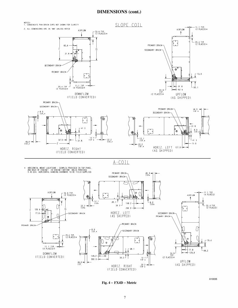
DIMENSIONS (cont.)
SLOPE COIL
A-COIL
NOTES:1. CONDENSATE PAN DRAIN CAPS NOT SHOWN FOR CLARITY. 2. ALL DIMENSIONS ARE IN "MM" UNLESS NOTED.
* HORIZONTAL MOUNT LOCATIONS - DIMPLES PROVIDED IN TOP PANEL, AND BACK OF CABINET. IN CABINET BOTTOM. HOLES PROVIDED 3.45 DIA. HORIZONTAL HANGING HARDWARE TO BE FIELD SUPPLIED.
31.8
82.6
25.4 TYP.(2 PLACES)*
11.1 TYP.(4 PLACES)*
55.6 TYP.(2 PLACES)*
GF
AIRFLOW
SECONDARY DRAIN
PRIMARY DRAIN
DOWNFLOW(FIELD CONVERTED)
22.2TYP.*
12.7TYP.*54.0
41.3
46.0TYP.*
8.0TYP.*
F31.8
PRIMARY DRAIN
SECONDARY DRAIN
HORIZ. RIGHT(FIELD CONVERTED)
41.3
46.0TYP.*
8.0TYP.*
22.2TYP.*
73.0
127.0
31.8
12.7TYP.*
SECONDARY DRAIN
PRIMARY DRAIN
HORIZ. LEFT(AS SHIPPED)
82.665.1
73.0
55.6TYP.
(2 PLACES)*
11.1 TYP.(2 PLACES)*
25.4 TYP.(2 PLACES)*
31.8
AIRFLOW
SECONDARY DRAIN
PRIMARY DRAIN
UPFLOW(AS SHIPPED)
200.030.2
38.1
46.0TYP*
8.0TYP*
22.2TYP*
12.7TYP* 149.2
PRIMARY DRAIN
SECONDARY DRAIN
HORIZ. LEFT(AS SHIPPED)
55.6TYP.
(2 PLACES)*
25.4 TYP.(2 PLACES)
11.1 TYP.(4 PLACES)
68.3
79.4
77.8
120.6
AIRFLOW
UPFLOW(AS SHIPPED)
PRIMARY DRAIN
SECONDARY DRAIN
200.030.2
38.1
12.7TYP.*
46.0TYP.
149.2
8.0TYP.*
22.2TYP.*HORIZ. RIGHT
(FIELD CONVERTED)
PRIMARY DRAIN
SECONDARY DRAIN
25.4 TYP.(2 PLACES)*
11.1 TYP,(4 PLACES)*
120.6
77.8
F
55.6 TYP.(2 PLACES)*
G
AIRFLOW
DOWNFLOW(FIELD CONVERTED)
SECONDARY DRAIN
PRIMARY DRAIN
A10035
Fig. 4 − FX4D − Metric

8
PHYSICAL DATA
ODS CATALOGORDERING NO.
FACTORYINSTALLEDHEAT (kW)
NOMINAL COOLINGCAPACITY (Btuh)
DIMENSIONS SHIPPINGWEIGHTHeight Width Depth
FX4DNF019(0,T,L)00 -18,000
49 5/8-in1261mm
17 5/8-in447mm
22-1/16-in560mm
122 lb55 kgFX4DNF019(0,L)05 5
FX4DNF025(0,T,L)00 -24,000
49 5/8-in1261mm
17 5/8-in447mm
22-1/16-in560mm
122 lb55 kgFX4DNF025(0,L)05 5
FX4DNF031(0,T,L)00 -30,000
53 7/16-in1357mm
21 1/8-in536mm
22-1/16-in560mm
146 lb66 kgFX4DNF031(0,L)08 8
FX4DNF037(0,T,L)00 -36,000
49 5/8-in1261mm
21 1/8-in536mm
22-1/16-in560mm
157 lb71 kgFX4DNF037(0,L)10 10
FX4DNF043(0,T,L)00 -42,000
49 5/8-in1260mm
21 1/8-in536mm
22-1/16-in560mm
157 lb71 kgFX4DNF043(0,L)10 10
FX4DNF049(0,T,L)00 -48,000
53 7/16-in1357mm
24 11/16-in627mm
22-1/16-in560mm
185 lb84 kgFX4DNF049(0,L)10 10
FX4DNF061(0,T,L)00 -
60,00059 3/16-in1503mm
24 11/16-in627mm
22-1/16-in560mm
201 lb91 kg
FX4DNF061(0,L)10 10
FX4DNF061(0,L)15 15
FX4DNB031(T,L)00 - 30,00053 7/16-in1357mm
21 1/8-in536mm
22-1/16-in560mm
146 lb66 kg
FX4DNB037(T,L)00 - 36,00053 7/16-in1357mm
21 1/8-in536mm
22-1/16-in560mm
175 lb79kg
FX4DNB043(T,L)00 - 42,00053 7/16-in1357mm
21 1/8-in536mm
22-1/16-in560mm
175 lb79kg
FX4DNB049(T,L)00 - 48,00053 7/16-in1357mm
24 11/16-in627mm
22-1/16-in560mm
185 lb84 kg
FX4DNB061(T,L)00 - 60,00059 3/16-in1503mm
24 11/16-in627mm
22-1/16-in560mm
201 lb91 kg
6th digit: B - Modular cabinet, F - Single piece cabinet
10th digit: 0 - Copper, T - Tin-Plate, L - Aluminum
SPECIFICATIONSMODEL FX4D 019 025 031 037 043 049 061
COIL
Puron� Refrigerant Metering Device
TXV - factory installed hard-shutoff, bi-flow type for heat pump application
TXV 2 ton 3 ton 4 ton
Rows/Fins Per In. 3 / 14.5
Face Area (Sq. Ft.) 2.97 3.46 4.45 5.93 7.42
Configuration Slope A
FAN
CFM (Nominal) 600 800 1000 1200 1400 1600 2000
Motor Type (ECM) Multi-tap ECM
Motor Hp 1/3 1/3 1/2 1/2 1/2 3/4 3/4
FILTER
21-1/2-in / 546 mm X 16-3/8-in / 417 mm 19-7/8-in / 505 mm 23-5/16-in / 585 mm
CABINET CONFIGURATION OPTIONS
1-pc 1-pc / Modular

9
PERFORMANCE DATAAIRFLOW PERFORMANCE (CFM)
MODEL &SIZE
BLOWERSPEED
0.10 0.20 0.30 0.40 0.50 0.60
FX4D 019
Tap 5 776 745 696 660 609 572
Tap 4 683 644 589 548 494 461
Tap 3 683 644 589 548 494 461
Tap 2 631 563 500 443 409 361
Tap 1 625 524 457 417 367 319
FX4D 025
Tap 5 956 920 891 851 816 780
Tap 4 825 795 757 722 674 634
Tap 3 825 795 757 722 674 634
Tap 2 726 695 635 598 543 509
Tap 1 631 563 500 443 409 361
FX4D 031
Tap 5 1189 1151 1104 1050 1003 959
Tap 4 1041 998 944 886 837 772
Tap 3 1041 998 944 886 837 772
Tap 2 924 876 817 752 704 660
Tap 1 779 693 628 571 526 476
FX4D 037
Tap 5 1363 1332 1294 1253 1207 1157
Tap 4 1237 1206 1160 1121 1070 1013
Tap 3 1237 1206 1160 1121 1070 1013
Tap 2 1095 1058 1007 951 888 824
Tap 1 1014 885 773 673 609 549
FX4D 043
Tap 5 1519 1490 1454 1419 1379 1332
Tap 4 1437 1403 1366 1333 1294 1245
Tap 3 1437 1403 1366 1333 1294 1245
Tap 2 1257 1226 1191 1141 1090 1033
Tap 1 1237 1206 1160 1121 1070 1013
FX4D 049
Tap 5 1757 1725 1693 1653 1614 1576
Tap 4 1664 1626 1593 1552 1517 1477
Tap 3 1664 1626 1593 1552 1517 1477
Tap 2 1459 1420 1379 1336 1298 1259
Tap 1 1301 1241 1195 1150 1102 1039
FX4D 061
Tap 5 2030 1995 1961 1927 1888 1842
Tap 4 1811 1775 1740 1703 1664 1613
Tap 3 1811 1775 1740 1703 1664 1613
Tap 2 1665 1632 1593 1556 1507 1453
Tap 1 1462 1418 1371 1327 1278 1228
- Airflow above 450 cfm/ton.
NOTES:
1. Airflow based upon dry coil at 230v with factory−approved filter and electric heater (2 element heater sizes 018 through 037, 3 elementheater sizes 043 through 061).
2. Airflow at 208 volts is approximately the same as 230 volts because the multi−tap ECM motor is a constant torque motor. The torquedoesn’t drop off at the speeds the motor operates.
3. To avoid potential for condensate blowing out of drain pan prior to making drain trap:Return static pressure must be less than 0.40 in wc.Horizontal applications of 043 − 061 sizes must have supply static greater than 0.20 in wc.
4. Airflow above 400 cfm/ton on 049−061 size could result in condensate blowing off coil or splashing out of drain pan.

10
PERFORMANCE DATA (cont.)
GROSS COOLING CAPACITIES (MBH) − PURON� REFRIGERANT
UNITSIZE
INDOOR COILAIR
SATURATED TEMPERATURE LEAVING EVAPORATOR (�F / �C)
35 / 2 40 / 4 45 / 7 50 / 10 55 / 13
CFM EWB TC SHC BF TC SHC BF TC SHC BF TC SHC BF TC SHC BF
FX4D019
525
72 / 22 36 19 0.00 33 17 0.00 28 15 0.00 24 13 0.00 19 11 0.0167 / 19 29 19 0.01 26 17 0.01 22 15 0.02 17 13 0.02 12 10 0.0262 / 17 23 19 0.02 20 17 0.02 16 15 0.02 12 12 0.07 10 10 0.24
600
72 / 22 40 21 0.00 36 19 0.00 32 17 0.00 27 14 0.01 21 12 0.0267 / 19 33 21 0.02 29 19 0.02 24 17 0.02 19 14 0.02 13 12 0.0362 / 17 26 21 0.02 22 19 0.02 17 17 0.03 13 13 0.08 11 11 0.25
675
72 / 22 44 23 0.00 40 21 0.00 35 18 0.00 29 16 0.02 23 13 0.0267 / 19 36 23 0.02 32 21 0.03 26 18 0.03 21 16 0.03 15 13 0.0362 / 17 29 24 0.03 24 21 0.03 19 19 0.04 15 15 0.10 12 12 0.26
FX4D025
700
72 / 22 48 25 0.00 43 22 0.00 37 19 0.00 31 17 0.02 25 14 0.0367 / 19 39 25 0.03 34 22 0.03 28 20 0.03 22 17 0.03 16 14 0.0462 / 17 31 25 0.03 26 23 0.03 20 20 0.04 16 16 0.10 13 13 0.26
800
72 / 22 53 27 0.00 47 24 0.00 41 21 0.01 35 18 0.03 27 15 0.0467 / 19 43 28 0.04 37 25 0.04 31 22 0.04 25 19 0.04 17 16 0.0562 / 17 34 28 0.04 29 25 0.04 23 22 0.05 18 18 0.12 15 15 0.28
900
72 / 22 57 30 0.00 51 27 0.00 45 23 0.03 38 20 0.04 30 17 0.0567 / 19 47 30 0.05 41 27 0.05 34 24 0.05 27 21 0.05 19 17 0.0662 / 17 37 31 0.05 31 28 0.05 25 24 0.06 20 20 0.14 16 16 0.29
FX4D031
875
72 / 22 59 30 0.00 53 27 0.00 46 24 0.01 38 20 0.02 30 17 0.0367 / 19 48 31 0.03 42 28 0.03 35 24 0.04 27 21 0.04 19 17 0.0462 / 17 38 31 0.04 32 28 0.04 25 24 0.04 20 20 0.11 16 16 0.27
1000
72 / 22 65 33 0.00 58 30 0.00 51 26 0.02 42 23 0.04 33 19 0.0467 / 19 53 34 0.04 46 31 0.04 38 27 0.05 30 23 0.05 21 19 0.0562 / 17 42 35 0.05 35 31 0.05 28 27 0.06 22 22 0.13 18 18 0.29
1125
72 / 22 71 36 0.00 63 33 0.00 55 29 0.03 46 25 0.05 36 20 0.0567 / 19 58 37 0.05 50 33 0.05 42 29 0.06 33 25 0.06 23 21 0.0762 / 17 46 38 0.06 38 34 0.06 30 30 0.07 24 24 0.15 20 20 0.30
FX4D037
1050
72 / 22 67 36 0.00 60 32 0.00 52 28 0.00 44 24 0.02 35 20 0.0367 / 19 54 37 0.03 47 33 0.03 40 29 0.03 31 25 0.03 22 20 0.0462 / 17 43 37 0.03 36 33 0.03 29 29 0.04 22 22 0.10 18 18 0.26
1200
72 / 22 74 40 0.00 66 36 0.00 58 31 0.01 48 27 0.03 38 22 0.0467 / 19 60 41 0.04 52 36 0.04 44 32 0.04 35 27 0.04 24 23 0.0562 / 17 48 41 0.04 40 37 0.04 32 32 0.05 25 25 0.12 21 21 0.28
1350
72 / 22 81 43 0.00 72 39 0.00 63 34 0.03 53 30 0.04 41 25 0.0567 / 19 66 45 0.05 57 40 0.05 48 35 0.05 38 30 0.05 27 25 0.0662 / 17 52 46 0.05 44 41 0.05 35 36 0.06 28 28 0.14 23 23 0.29
FX4D043
1225
72 / 22 79 41 0.00 71 37 0.00 62 33 0.02 52 28 0.03 41 23 0.0467 / 19 64 42 0.04 56 38 0.04 47 33 0.04 37 29 0.04 26 24 0.0562 / 17 51 43 0.04 43 38 0.04 34 34 0.05 27 27 0.12 22 22 0.28
1400
72 / 22 87 46 0.00 78 41 0.00 68 36 0.03 57 31 0.04 45 26 0.0567 / 19 71 47 0.05 62 42 0.05 52 37 0.05 41 32 0.05 29 26 0.0662 / 17 56 48 0.06 47 43 0.06 38 38 0.06 30 30 0.14 25 25 0.29
1575
72 / 22 95 50 0.00 85 45 0.00 74 39 0.04 62 34 0.05 48 28 0.0667 / 19 77 51 0.06 67 46 0.06 56 40 0.06 44 35 0.07 31 29 0.0762 / 17 61 52 0.07 51 47 0.07 41 41 0.08 33 33 0.17 27 27 0.31
FX4D049
1400
72 / 22 90 48 0.00 81 43 0.00 71 38 0.00 59 32 0.02 47 27 0.0367 / 19 73 49 0.03 64 44 0.03 54 38 0.03 42 33 0.03 30 27 0.0462 / 17 58 49 0.03 49 44 0.03 39 39 0.04 30 30 0.10 25 25 0.26
1600
72 / 22 100 53 0.00 89 48 0.00 78 42 0.01 65 36 0.03 51 30 0.0467 / 19 81 54 0.04 71 48 0.04 59 43 0.04 47 36 0.04 33 30 0.0562 / 17 65 55 0.04 54 49 0.04 43 43 0.05 34 34 0.12 28 28 0.28
1800
72 / 22 109 58 0.00 97 52 0.00 85 46 0.03 71 39 0.04 56 33 0.0567 / 19 89 59 0.05 77 53 0.05 65 47 0.05 51 40 0.05 36 33 0.0662 / 17 70 60 0.05 59 54 0.05 47 48 0.06 37 37 0.14 31 31 0.29
FX4D061
1600
72 / 22 109 57 0.00 98 51 0.00 86 45 0.00 73 39 0.01 58 32 0.0267 / 19 89 58 0.02 78 52 0.02 66 46 0.02 52 39 0.03 37 33 0.0362 / 17 71 59 0.03 60 52 0.03 48 46 0.03 37 37 0.09 31 31 0.24
1750
72 / 22 117 61 0.00 105 55 0.00 92 48 0.01 78 41 0.02 62 35 0.0267 / 19 95 62 0.03 84 56 0.03 70 49 0.03 56 42 0.03 40 35 0.0362 / 17 76 63 0.03 64 56 0.03 51 50 0.04 40 40 0.10 33 33 0.25
2000
72 / 22 129 67 0.00 116 60 0.00 102 53 0.02 86 46 0.03 68 38 0.0367 / 19 105 69 0.04 92 62 0.04 78 54 0.04 62 47 0.04 44 39 0.0562 / 17 84 70 0.04 71 63 0.04 57 55 0.05 45 45 0.12 37 37 0.27
See Notes following table.

11
PERFORMANCE DATA (cont)CFM - Cubic Ft per Minute EWB - Entering Wet Bulb �F (�C) LWB - Leaving Wet Bulb �F (�C) TC - Gross Cooling Capacity 1000 BtuhSHC - Gross Sensible Capacity 1000Btuh
BF - Bypass Factor MBH - 1000 Btuh
NOTES:
1. Contact manufacturer for cooling capacities at conditionsother than shown in table.
2. Formulas:Leaving db = entering db −sensible heat cap. 1.09 x CFMLeaving wb = wb corresponding to enthalpy of air leavingcoil (hlwb)hlwb = hewb −total capacity (Btuh) 4.5 x CFMwhere hewb = enthalpy of air entering coil. Direct interpola-tion is permissible. Do not extrapolate.
3. SHC is based on 80�F (27�C) db temperature of air enter-ing coil. Below 80�F (27�C) db, subtract (Correction Fact-or x CFM) from SHC. Above 80�F (27�C) db, add (Cor-rection Factor x CFM) to SHC.
4. Bypass Factor = 0 indicates no psychometric solution. Usebypass factor of next lower EWB for approximation.
SHC CORRECTION FACTOR
BYPASSFACTOR
ENTERING AIR DRY-BULB TEMPERATURE (�F)
79 78 77 76 75 Under 75
81 82 83 84 85 Over 85
ENTERING AIR DRY-BULB TEMPERATURE (�C)
26 25 25 24 24 Under 75
27 28 28 29 29 Over 85
Correction Factor
0.10 .098 1.96 2.94 3.92 4.91 Useformulashownbelow
0.20 0.87 1.74 2.62 3.49 4.36
0.30 0.76 1.53 2.29 3.05 3.82
Interpolation is permissible.
Correction Factor = 1.09 x (1 - BF) x (db - 80)
MINIMUM CFM AND MOTOR SPEED SELECTIONFAN COIL SIZES
FX
HEATER kW
3 5 8 9 10 15 18 20 24 30
019 525 525 525 — 600* — — — — —
025 700 700 700 — 700 775* — — — —
031 — 875 875 — 875 875 — 1060* — —
037 — 1050 970 970 970 920 — 1040 — —
043 — — 1225 1225 1225 1225 1225 1225 — —
049 — — 1400 1400 1400 1400 1400 1400 1400 1400
061 — — 1750 1750 1750 1750 1750 1750 1750 1750
* Indicates medium speed (blue). All other motor speeds at low tap.
AIR DELIVERY PERFORMANCE CORRECTION COMPONENT PRESSURE DROP (in wc)AT INDICATED AIRFLOW (DRY−TO−WET COIL)
FXSIZE
CFM
500 600 700 800 900 1000 1100 1200 1300 1400 1500 1600 1700 1800 1900 2000
019 0.034 0.049 0.063 -- -- -- -- -- -- -- -- -- -- -- -- --
025 0.016 0.027 0.038 0.049 0.059 -- -- -- -- -- -- -- -- -- -- --
031 -- -- -- 0.049 0.059 0.070 0.080 -- -- -- -- -- -- -- -- --
037 -- -- -- -- -- 0.055 0.064 0.073 0.081 -- -- -- -- -- -- --
043 -- -- -- -- -- -- -- 0.049 0.056 0.063 0.070 -- -- -- -- --
049 -- -- -- -- -- -- -- -- -- 0.038 0.043 0.049 0.054 0.059 -- --
061 -- -- -- -- -- -- -- -- -- -- -- 0.027 0.031 0.035 0.039 0.043
12
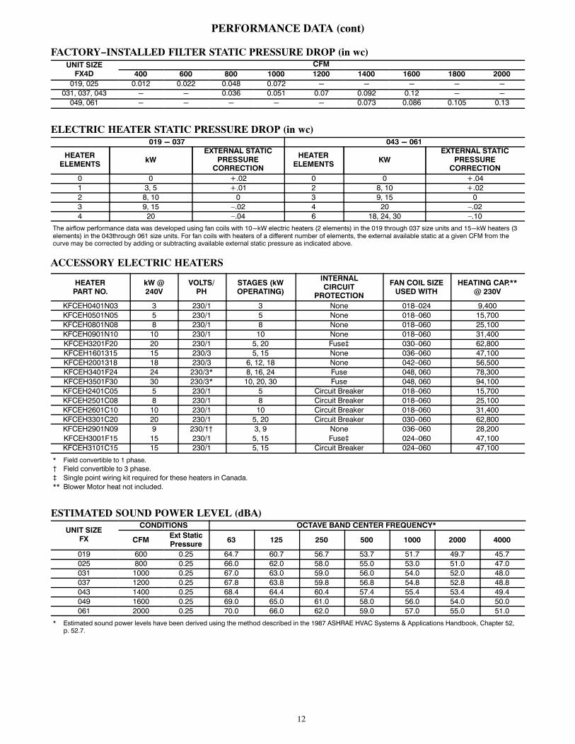
PERFORMANCE DATA (cont)
FACTORY−INSTALLED FILTER STATIC PRESSURE DROP (in wc)UNIT SIZE
FX4D
CFM
400 600 800 1000 1200 1400 1600 1800 2000
019, 025 0.012 0.022 0.048 0.072 - - - - -
031, 037, 043 - - 0.036 0.051 0.07 0.092 0.12 - -
049, 061 - - - - - 0.073 0.086 0.105 0.13
ELECTRIC HEATER STATIC PRESSURE DROP (in wc)019 - 037 043 - 061
HEATERELEMENTS
kW
EXTERNAL STATICPRESSURE
CORRECTION
HEATERELEMENTS
KW
EXTERNAL STATICPRESSURE
CORRECTION
0 0 +.02 0 0 +.04
1 3, 5 +.01 2 8, 10 +.02
2 8, 10 0 3 9, 15 0
3 9, 15 –.02 4 20 –.02
4 20 –.04 6 18, 24, 30 –.10
The airflow performance data was developed using fan coils with 10-kW electric heaters (2 elements) in the 019 through 037 size units and 15-kW heaters (3elements) in the 043through 061 size units. For fan coils with heaters of a different number of elements, the external available static at a given CFM from thecurve may be corrected by adding or subtracting available external static pressure as indicated above.
ACCESSORY ELECTRIC HEATERS
HEATERPART NO.
kW @240V
VOLTS/PH
STAGES (kWOPERATING)
INTERNALCIRCUIT
PROTECTION
FAN COIL SIZEUSED WITH
HEATING CAP.**@ 230V
KFCEH0401N03 3 230/1 3 None 018–024 9,400
KFCEH0501N05 5 230/1 5 None 018–060 15,700
KFCEH0801N08 8 230/1 8 None 018–060 25,100
KFCEH0901N10 10 230/1 10 None 018–060 31,400
KFCEH3201F20 20 230/1 5, 20 Fuse� 030–060 62,800
KFCEH1601315 15 230/3 5, 15 None 036–060 47,100
KFCEH2001318 18 230/3 6, 12, 18 None 042–060 56,500
KFCEH3401F24 24 230/3* 8, 16, 24 Fuse 048, 060 78,300
KFCEH3501F30 30 230/3* 10, 20, 30 Fuse 048, 060 94,100
KFCEH2401C05 5 230/1 5 Circuit Breaker 018–060 15,700
KFCEH2501C08 8 230/1 8 Circuit Breaker 018–060 25,100
KFCEH2601C10 10 230/1 10 Circuit Breaker 018–060 31,400
KFCEH3301C20 20 230/1 5, 20 Circuit Breaker 030–060 62,800
KFCEH2901N09 9 230/1� 3, 9 None 036–060 28,200
KFCEH3001F15 15 230/1 5, 15 Fuse� 024–060 47,100
KFCEH3101C15 15 230/1 5, 15 Circuit Breaker 024–060 47,100
* Field convertible to 1 phase.
� Field convertible to 3 phase.
� Single point wiring kit required for these heaters in Canada.
** Blower Motor heat not included.
ESTIMATED SOUND POWER LEVEL (dBA)
UNIT SIZEFX
CONDITIONS OCTAVE BAND CENTER FREQUENCY*
CFMExt StaticPressure
63 125 250 500 1000 2000 4000
019 600 0.25 64.7 60.7 56.7 53.7 51.7 49.7 45.7
025 800 0.25 66.0 62.0 58.0 55.0 53.0 51.0 47.0
031 1000 0.25 67.0 63.0 59.0 56.0 54.0 52.0 48.0
037 1200 0.25 67.8 63.8 59.8 56.8 54.8 52.8 48.8
043 1400 0.25 68.4 64.4 60.4 57.4 55.4 53.4 49.4
049 1600 0.25 69.0 65.0 61.0 58.0 56.0 54.0 50.0
061 2000 0.25 70.0 66.0 62.0 59.0 57.0 55.0 51.0
* Estimated sound power levels have been derived using the method described in the 1987 ASHRAE HVAC Systems & Applications Handbook, Chapter 52,p. 52.7.

13
ELECTRICAL DATA FOR UNITS WITH FACTORY−INSTALLED HEAT
FX4DNFMODEL NO.
MTRHP
MTRFLA
VOLTS/PH/HZ
HEAT PACKINSTALLED
MKFCEH
SINGLE CIRCUIT DUAL CIRCUIT
HeaterAmps
MCA MOCP
Htr.Amps
MCA MOCPHtr.
AmpsMCA MOCP
L1/L2 L1/L2 L1/L2 L3/L4 L3/L4 L3/L4
019(0,L)05 1/3 2.8 208/230/1/60 0501N05 18.1/20.0 26.1/28.5 30/30 N/A N/A N/A N/A N/A N/A
025(0,L)05 1/3 2.8 208/230/1/60 0501N05 18.1/20.0 26.1/28.5 30/30 N/A N/A N/A N/A N/A N/A
031(0,L)08 1/2 4.1 208/230/1/60 0801N08 28.9/32.0 41.3/45.2 45/50 N/A N/A N/A N/A N/A N/A
037(0,L)10 1/2 4.1 208/230/1/60 0901N10 36.2/40.0 50.4/55.1 60/60 N/A N/A N/A N/A N/A N/A
043(0,L)10 1/2 4.1 208/230/1/60 0901N10 36.2/40.0 50.4/55.1 60/60 N/A N/A N/A N/A N/A N/A
049(0,L)10 3/4 6.0 208/230/1/60 0901N10 36.2/40.0 52.8/57.5 60/60 N/A N/A N/A N/A N/A N/A
061(0,L)10 3/4 6.0 208/230/1/60 0901N10 36.2/40.0 52.8/57.5 60/60 N/A N/A N/A N/A N/A N/A
061(0,T,L)015 3/4 6.0 208/230/1/60 1501F15 54.2/59.9 75.3/82.4 80/90 36.2/40.0 52.8/57.5 60/60 18.1/20.0 22.6/25.0 25/25MCA - Minimum Circuit Amps
MOCP - Maximum Overcurrent Protection
ELECTRICAL DATA FOR UNITS WITHOUT ELECTRICAL HEAT
MODEL NO.MTRHP
MTRFLA
VOLTS/PH/HZ
SINGLE CIRCUITBRANCH CIRCUITMIN WIRE SIZE*
AWGMCA
MAXIMUMOVERCURRENT
PROTECTION
FX4DNF019(0,T,L)00 1/3 2.8 208/230/1/60 3.5 15 14
FX4DNF025(0,T,L)00 1/3 2.8 208/230/1/60 3.5 15 14
FX4DNF031(0,T,L)00 1/2 4.1 208/230/1/60 5.1 15 14
FX4DNF037(0,T,L)00 1/2 4.1 208/230/1/60 5.1 15 14
FX4DNF043(0,T,L)00 1/2 4.1 208/230/1/60 5.1 15 14
FX4DNF049(0,T,L)00 3/4 6.0 208/230/1/60 7.5 15 14
FX4DNF061(0,T,L)00 3/4 6.0 208/230/1/60 7.5 15 14
FX4DNB031(T,L)00 1/2 4.1 208/230/1/60 5.1 15 14
FX4DNB037(T,L)00 1/2 4.1 208/230/1/60 5.1 15 14
FX4DNB043(T,L)00 1/2 4.1 208/230/1/60 5.1 15 14
FX4DNB049(T,L)00 3/4 6.0 208/230/1/60 7.5 15 14
FX4DNB061(T,L)00 3/4 6.0 208/230/1/60 7.5 15 14
* Use copper wire only. Use 75�C only in this application. When using non-metallic (NM) sheathed cable, wire size required should be based on that of 60�C
conductors, instead of wire sizes shown in table above per NEC Article 336-26.
NOTE: If branch circuit wire length exceeds 100 ft (30 m), consult NEC 215-2 to determine maximum wire length. Use 2% voltage drop.
FLA - Full Load Amps

14
AC
CE
SSO
RY
EL
EC
TR
IC H
EA
TE
R E
LE
CT
RIC
AL
DA
TA
HE
AT
ER
PA
RT
NO
.
kW
P H A S E
INT
ER
NA
LC
IRC
UIT
PR
OT
EC
T
ION
HE
AT
ER
AM
PS
208/2
30V
BR
AN
CH
CIR
CU
IT
Min
Am
pacit
y
208/2
30V
*M
in W
ire
Siz
e (
AW
G)
208/2
30V
†M
in G
nd
Wir
e S
ize
208/2
30V
Max F
use
/Ckt
Bkr
Am
ps
208/2
30V
Max W
ire
Le
ng
th
208/2
30V
(F
t)‡
Sin
gle
Cir
cu
it
Du
al C
ircu
itS
ing
leC
ircu
it
Du
al C
ircu
itS
ing
leC
ircu
it
Du
al C
ircu
itS
ing
leC
ircu
it
Du
al C
ircu
itS
ing
leC
ircu
it
Du
al C
ircu
itS
ing
leC
ircu
it
Du
al C
ircu
it
240v
208v
L1,l2
L3,L
4L
1,L
2L
3,L
4L
1,
L2
L3,
L4
L1,
L2
L3,L
4L
1,L
2L
3,L
4L
1,L
2L
3,L
4
KF
CE
H0401N
03
32
.31
No
ne
10
.9/1
2.0
——
15
.9/1
7.3
——
12
/12
——
12
/12
——
20
/20
——
67
/68
——
KF
CE
H0501N
05
15
3.8
1N
on
e1
8.1
/20
.0—
—2
6.0
/28
.4—
—1
0/1
0—
—1
0/1
0—
—3
0/3
0—
—6
6/6
6—
—
KF
CE
H0501N
05
25
3.8
1N
on
e1
8.1
/20
.0—
—3
1.2
/33
.5—
—8
/8—
—1
0/1
0—
—3
5/3
5—
—8
5/8
8—
—
KF
CE
H2401C
05
15
3.8
1C
kt
Bkr
18
.1/2
0.0
——
26
.0/2
8.4
——
10
/10
——
10
/10
——
30
/30
——
66
/66
——
KF
CE
H2401C
05
25
3.8
1C
kt
Bkr
18
.1/2
0.0
——
31
.2/3
3.5
——
8/8
——
10
/10
——
35
/35
——
85
/88
——
KF
CE
H0801N
08
86
.01
No
ne
28
.9/3
2.0
——
44
.7/4
8.5
——
8/8
——
10
/10
——
45
/50
——
59
/60
——
KF
CE
H2501C
08
86
.01
Ckt
Bkr
28
.9/3
2.0
——
44
.7/4
8.5
——
8/8
——
10
/10
——
45
/50
——
59
/60
——
KF
CE
H2901N
09
96
.81
No
ne
32
.8/3
6.0
——
49
.5/5
3.5
——
8/6
——
10
/10
——
50
/60
——
54
/87
——
KF
CE
H2901N
09**
96
.83
No
ne
18
.8/2
0.8
——
32
.0/3
4.5
——
8/8
——
10
/10
——
35
/35
——
83
/85
——
KF
CE
H0901N
10
10
7.5
1N
on
e3
6.2
/40
.0—
—5
3.8
/58
.5—
—6
/6—
—1
0/1
0—
—6
0/6
0—
—7
8/8
0—
—
KF
CE
H2601C
10
10
7.5
1C
kt
Bkr
36
.2/4
0.0
——
53
.8/5
8.5
——
6/6
——
10
/10
——
60
/60
——
78
/80
——
KF
CE
H3001F
15
15
11
.31
Fu
se
54
.2/5
9.9
36
.2/4
0.0
18
.1/2
0.0
76
.3/8
3.4
53
.8/5
8.5
22
.7/2
5.0
4/4
6/6
10
/10
8/8
10
/10
10
/10
80
/90
60
/60
25
/25
88
/89
78
/80
75
/76
KF
CE
H3101C
15
15
11
.31
Ckt
Bkr
—3
6.2
/40
.01
8.1
/20
.0—
53
.8/5
8.5
22
.7/2
5.0
—6
/61
0/1
0—
10
/10
10
/10
—6
0/6
02
5/2
5—
78
/80
75
/76
KF
CE
H1601315
15
11
.33
No
ne
31
.3/3
4.6
——
47
.7/5
1.8
——
8/6
——
10
/10
——
50
/60
——
56
/90
——
KF
CE
H2001318
18
13
.53
No
ne
37
.6/4
1.5
——
55
.5/6
0.4
——
6/6
——
10
/8—
—6
0/7
0—
—7
6/7
7—
—
KF
CE
H3201F
20
20
15
.01
Fu
se
72
.3/7
9.9
36
.2/4
0.0
36
.2/4
0.0
98
.9/1
08
.45
3.8
/58
.54
5.3
/50
.03
/26
/68
/88
/61
0/1
01
0/1
01
00
/11
06
0/6
05
0/5
08
5/1
09
78
/80
59
/59
KF
CE
H3301C
20
20
15
.01
Ckt
Bkr
—3
6.2
/40
.03
6.2
/40
.0—
53
.8/5
8.5
45
.3/5
0.0
—6
/68
/8—
10
/10
10
/10
—6
0/6
05
0/5
0—
78
/80
59
/59
KF
CE
H3401F
24††
24
18
.03
Fu
se
50
.1/5
5.4
——
71
.2/7
7.8
——
4/4
——
8/8
——
80
/80
——
94
/95
——
24
18
.01
Fu
se
86
.7/9
5.5
——
11
6.9
/12
7.9
——
1/1
——
6/6
——
12
5/1
50
——
11
5/1
16
——
KF
CE
H3501F
30††
30
22
.53
Fu
se
62
.6/6
9.2
——
86
.8/9
5.0
——
3/3
——
8/8
——
90
/10
0—
—9
7/9
8—
—
30
22
.51
Fu
se
10
9.0
/12
0.0
——
14
4.8
/15
8.5
——
0/0
0—
—6
/6—
—1
50
/17
5—
—1
17
/15
0—
—
FIE
LD
MU
LT
IPO
INT
WIR
ING
OF
24−
AN
D 3
0−kW
SIN
GL
E P
HA
SE
HE
AT
ER
PA
RT
NO
.
kW
P H A S E
HE
AT
ER
AM
PS
208/2
30V
MIN
AM
PA
CIT
Y208/2
30V
*M
IN W
IRE
SIZ
E (
AW
G)
208/2
30V
†M
IN G
ND
WIR
E S
IZE
208/2
30V
MA
X F
US
E/C
KT
BK
RA
MP
S208/2
30V
MA
X W
IRE
LE
NG
TH
208/2
30V
(F
T)‡
240V
208V
L1,L
2L
3,L
4L
5,L
6L
1,L
2L
3,L
4L
5,L
6L
1,L
2L
3,L
4L
5,L
6L
1,L
2L
3,L
4L
5,L
6L
1,L
2L
3,L
4L
5,L
6
KF
CE
H3
40
1F
24
††
24
18
.01
28
.9/3
2.0
28
.9/3
2.0
28
.9/3
2.0
44
.7/4
8.5
36
.2/4
0.0
36
.2/4
0.0
8/8
8/8
8/8
10
/10
45
/50
40
/40
40
/40
59
/60
73
/73
73
/73
KF
CE
H3
50
1F
30
††
30
22
.51
36
.2/4
0.0
36
.2/4
0.0
36
.2/4
0.0
53
.8/5
8.5
45
.3/5
0.0
45
.3/5
0.0
6/6
8/8
8/8
10
/10
60
/60
50
/50
50
/50
78
/80
59
/59
59
/59
*In
clu
des b
low
er
mo
tor
am
ps o
f la
rgest
fan
co
il u
sed
with
heate
r.
�C
op
per
wir
e m
ust
be u
sed
. If o
ther
than
un
co
ate
d (
no
n-
pla
ted
), 7
5�C
am
bie
nt,
co
pp
er
wir
e (
so
lid w
ire fo
r 1
0 A
WG
an
d s
malle
r, s
tran
ded
wir
e fo
r la
rger
than
10
AW
G)
is u
sed
, co
nsu
lt a
pp
licab
le t
ab
les o
fth
e N
atio
nal E
lectr
ic C
od
e (
AN
SI/
NF
PA
70
).
�Len
gth
sh
ow
n is a
s m
easu
red
1 w
ay a
lon
g w
ire p
ath
betw
een
un
it a
nd
serv
ice p
an
el fo
r a v
oltag
e d
rop
no
t to
exc
eed
2%
.
**
Fie
ld c
on
vert
ible
to
3 p
hase.
��
Fie
ld c
on
vert
ible
to
1 p
hase, sin
gle
or
mu
ltip
le s
up
ply
cir
cu
it.
NO
TE
S: 1
.F
or
fan
co
il siz
es 0
18
-0
37
.
2.
Fo
r fa
n c
oil
siz
es 0
42
-0
61
.
3.
Sin
gle
cir
cu
it a
pp
licatio
n o
f F
15
an
d F
20
heate
rs r
eq
uir
es s
ing
le-
po
int
wir
ing
kit a
ccesso
ry.
15
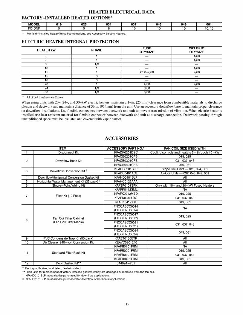
HEATER ELECTRICAL DATAFACTORY−INSTALLED HEATER OPTIONS*
MODEL 019 025 031 037 043 049 061
FX4DNF 5 5 8 10 10 10 10, 15
* For field-installed heater/fan coil combinations, see Accessory Electric Heaters.
ELECTRIC HEATER INTERNAL PROTECTION
HEATER kW PHASEFUSE
QTY/SIZECKT BKR*QTY/SIZE
5 1 — 1/60
8 1 — 1/60
9 1/3 — —
10 1 — 1/60
15 1 2/30–2/60 2/60
15 3 — —
18 3 — —
20 1 4/60 2/60
24 1/3 6/60 —
30 1/3 6/60 —
* All circuit breakers are 2 pole.
When using units with 20−, 24−, and 30−kW electric heaters, maintain a 1−in. (25 mm) clearance from combustible materials to dischargeplenum and ductwork and maintain a distance of 36 in. (914mm) from the unit. Use an accessory downflow base to maintain proper clearanceon downflow installations. Use flexible connectors between ductwork and unit to prevent transmission of vibration. When electric heater isinstalled, use heat resistant material for flexible connector between ductwork and unit at discharge connection. Ductwork passing throughunconditioned space must be insulated and covered with vapor barrier
ACCESSORIES
ITEM ACCESSORY PART NO.* FAN COIL SIZE USED WITH
1. Disconnect Kit KFADK0201DSC Cooling controls and heaters 3- through 10-kW
2. Downflow Base Kit
KFACB0201CFB 019, 025
KFACB0301CFB 031, 037, 043
KFACB0401CFB 049, 061
3. Downflow Conversion Kit �KFADC0201SLP Slope Coil Units — 019, 024, 031
KFADC0401ACL A-Coil Units — 037, 043, 049, 061
4. Downflow/Horizontal Conversion Gasket Kit KFAHD0101SLP All
5. Horizontal Water Management Kit (25 pack) � KFAHC0125AAA All
6. Single-Point Wiring Kit KFASP0101SPK Only with 15- and 20-kW Fused Heaters
7. Filter Kit (12 Pack)
KFAFK0112SML NA
KFAFK0212MED 019, 025
KFAFK0312LRG 031, 037, 043
KFAFK0412XXL 049, 061
8.Fan Coil Filter Cabinet(Fan Coil Filter Media)
FNCCABCC0014(FILXXFNC0014)
NA
FNCCABCC0017(FILXXFNC0017)
019, 025
FNCCABCC0021(FILXXFNC0021)
031, 037, 043
FNCCABCC0024(FILXXFNC0024)
049, 061
9. PVC Condensate Trap Kit (50 pack) KFAET0150ETK All
10. Air Cleaner 240-volt Conversion Kit KEAVC0201240 All
11. Standard Filter Rack Kit
KFAFR0101FRM NA
KFAFR0201FRM 019, 025
KFAFR0301FRM 031, 037, 043
KFAFR0401FRM 049, 061
12. Door Gasket Kit** 344994-751 All
* Factory authorized and listed, field-installed.
** This kit is for replacement of factory installed gaskets if they are damaged or removed from the fan coil. � KFAHD0101SLP must also be purchased for downflow applications.
� KFAHD0101SLP must also be purchased for downflow or horizontal applications.

16
ACCESSORY KITS DESCRIPTION SUGGESTED AND REQUIRED USE
Disconnect KitThe kit is used to disconnect electrical power to the fan coil soservice or maintenance may be performed safely. SUGGESTED USE: Units for 3− through 10−kW electricresistance heaters and cooling controls.
Downflow Base KitThis kit is designed to provide a 1−in. minimum clearance betweenunit discharge plenum, ductwork, and combustible materials. Italso provides a gap−free seal with the floor.REQUIRED USE: This kit must be used whenever fan coils areused in downflow applications.
Downflow Conversion KitFan coils are shipped from the factory for upflow or horizontal−leftapplications. Downflow conversion kits provide proper condensatewater drainage and support for the coil when used in downflowapplications. Separate kits are available for slope coils and A−coils.
REQUIRED USE: This kit must be used whenever fan coils areused in downflow applications.
Downflow/Horizontal Conversion Gasket KitThis kit provides the proper gasketing of units when applied ineither a downflow or horizontal application.REQUIRED USE: Fan coils in either downflow or horizontalapplications.
Horizontal Applications − Water Management KitThis kit provides proper installation of fan coils under conditionsof high static pressure and high relative humidity.SUGGESTED USE: All fan coils.
Single Point Wiring KitThe single point wiring kit acts as a jumper between L1 and L3lugs, and between the L2 and L4 lugs. This allows the installer torun two heavy−gauge, high−voltage wires into the fan coil ratherthan 4 light−gauge, high−voltage wires. SUGGESTED USE: Fan coils with 15− and 20−kW fused heatersonly.
Filter Kit (12 pack)The kit consists of 12 fan coil framed filters. These filters collectlarge dust particles from the return air entering the fan coil and
prevents them from collecting on the coil. This process helps tokeep the coil clean, which increases heat transfer and, in turn, theefficiency of the system.SUGGESTED USE: To replace filters in fan coils.REQUIRED USE: All units unless a filter grille is used.
Fan Coil Filter CabinetThis cabinet is mounted to the fan coil on the return air end anddesigned to slip over the outer fan coil casing. The cabinets areinsulated using the same insulation as production fan coils. Theyare designed for the removal of particulates from indoor air usingFILXXFNC00(14, 17, 21, 24) media filter cartridges. These fancoil media filter cartridge kits are designed for the removal ofparticles from indoor air. The cartridge is installed in the return airduct next to the air handler or further upstream.SUGGESTED USE: All fan coils.
Condensate Drain Trap KitThis kit consists of 50 PVC condensate traps. Each trap ispre−formed and ready for field installation. This deep trap helps thesystem make and hold proper condensate flow even during blowerinitiation.SUGGESTED USE: All fan coils.
Air Cleaner 240−volt Conversion KitThe AIRA electronic air cleaner comes ready for 115−v operation.REQUIRED USE: This kit is required when running 240−voltcircuit to air cleaner.
Standard Filter Rack KitThis kit mounts in fan coil filter rack area and modifies the existingfilter rack to support standard 1−in. filter sizes.SUGGESTED USE: Fan coils using standard filter sizes.
Low Air Leakage KitThis kit is available through MicroMetl and when installed as perthe instructions provided in the kit, is designed to meet thestringent 1.4% air leakage @0.5” water requirement as set byCalifornia Title 24 code. To order this kit, call MicroMetlCustomer Service Department at 800.884.4662.
Door Gasket KitThis kit consists of specific adhesive−backed foam strips which are applied to the unit door frame, limiting air leakage.
Copyright 2019 Carrier Corp. � 7310 W. Morris St. � Indianapolis, IN 46231 Edition Date: 07/19
Manufacturer reserves the right to change, at any time, specifications and designs without notice and without obligations.
Catalog No: FX4D-07PD
Replaces: FX4D-06PD