CGPSC 2016 EXAM NOTIFICATION - · PDF fileCGPSC 2016 EXAM NOTIFICATION -

Product change notification
C&K components C&K components SAS - 1 rue Louis de la Verne B.P. 359 F-39105 Dole Cedex - FRANCE Telephone: +33 (0)3 84 72 94 37 - Facsimile: +33 (0)3 84 79 20 39 – www.ck-components.com Document subject to change without prior notice Diffusion: no restriction PCN09-3-CCM Rev.B – Feb 16, 2009 Page 1/9
Product change notification
PCN09-3-CCM

Product change notification
C&K components C&K components SAS - 1 rue Louis de la Verne B.P. 359 F-39105 Dole Cedex - FRANCE Telephone: +33 (0)3 84 72 94 37 - Facsimile: +33 (0)3 84 79 20 39 – www.ck-components.com Document subject to change without prior notice Diffusion: no restriction PCN09-3-CCM Rev.B – Feb 16, 2009 Page 2/9
Document revision Revision Date Description Author
A February 16, 2009 Creation J. Smolinski B February 16, 2009 Modification in Annex 1 of
CCM01-2270 description and equivalent in New version
J. Smolinski

Product change notification
C&K components C&K components SAS - 1 rue Louis de la Verne B.P. 359 F-39105 Dole Cedex - FRANCE Telephone: +33 (0)3 84 72 94 37 - Facsimile: +33 (0)3 84 79 20 39 – www.ck-components.com Document subject to change without prior notice Diffusion: no restriction PCN09-3-CCM Rev.B – Feb 16, 2009 Page 3/9
Summary 1. Purpose........................................................................................................................................... 4 2. Change definition ............................................................................................................................ 4 3. Change impact................................................................................................................................ 4
3.1 Coplanarity .................................................................................................................................... 4 3.2 Insulator resistance ....................................................................................................................... 5 3.3 Card detect switch sealing to dust ................................................................................................ 6 3.4 Changes........................................................................................................................................ 6
4. Application ...................................................................................................................................... 7 4.1 Overview ....................................................................................................................................... 7 4.2 Product range affected........................................................................................................... 7 4.3 Date of application & time frame............................................................................................ 7 4.4 Ordering, pricing and stock handling policy ........................................................................... 7 4.5 Customer qualification............................................................................................................ 8
5 Acknowledgement........................................................................................................................... 8 6 Support ........................................................................................................................................... 8

Product change notification
C&K components C&K components SAS - 1 rue Louis de la Verne B.P. 359 F-39105 Dole Cedex - FRANCE Telephone: +33 (0)3 84 72 94 37 - Facsimile: +33 (0)3 84 79 20 39 – www.ck-components.com Document subject to change without prior notice Diffusion: no restriction PCN09-3-CCM Rev.B – Feb 16, 2009 Page 4/9
1. Purpose Following the development of new constraint and usage related to the smart card connector in its environment we’ve released a new generation of CCM01-MK2 (V2) to replace completely the existing products (V1)
2. Change definition The target of this new product is to improve the robustness of the product but also of its processing:
o Coplanarity o Insulator resistance
Card guide wall resistance to extreme insertion Card stop breakage
o Card detection switch dust sealing
3. Change impact
3.1 Coplanarity
V1 version Crimped PCF (inserted contacts into a plastic block being crimped on main insulator) V2 version Individual contact crimping
Product change notification
C&K components C&K components SAS - 1 rue Louis de la Verne B.P. 359 F-39105 Dole Cedex - FRANCE Telephone: +33 (0)3 84 72 94 37 - Facsimile: +33 (0)3 84 79 20 39 – www.ck-components.com Document subject to change without prior notice Diffusion: no restriction PCN09-3-CCM Rev.B – Feb 16, 2009 Page 5/9
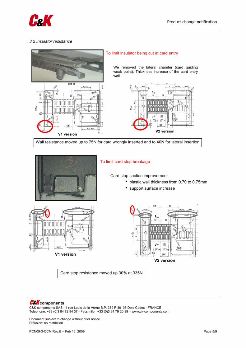
3.2 Insulator resistance
To limit insulator being cut at card entry
We removed the lateral chamfer (card guiding weak point): Thickness increase of the card entry wall
V1 version V2 version
Wall resistance moved up to 75N for card wrongly inserted and to 40N for lateral insertion
Card stop section improvement • plastic wall thickness from 0.70 to 0.75mm • support surface increase
To limit card stop breakage
V1 version V2 version
Card stop resistance moved up 30% at 335N
Product change notification
C&K components C&K components SAS - 1 rue Louis de la Verne B.P. 359 F-39105 Dole Cedex - FRANCE Telephone: +33 (0)3 84 72 94 37 - Facsimile: +33 (0)3 84 79 20 39 – www.ck-components.com Document subject to change without prior notice Diffusion: no restriction PCN09-3-CCM Rev.B – Feb 16, 2009 Page 6/9
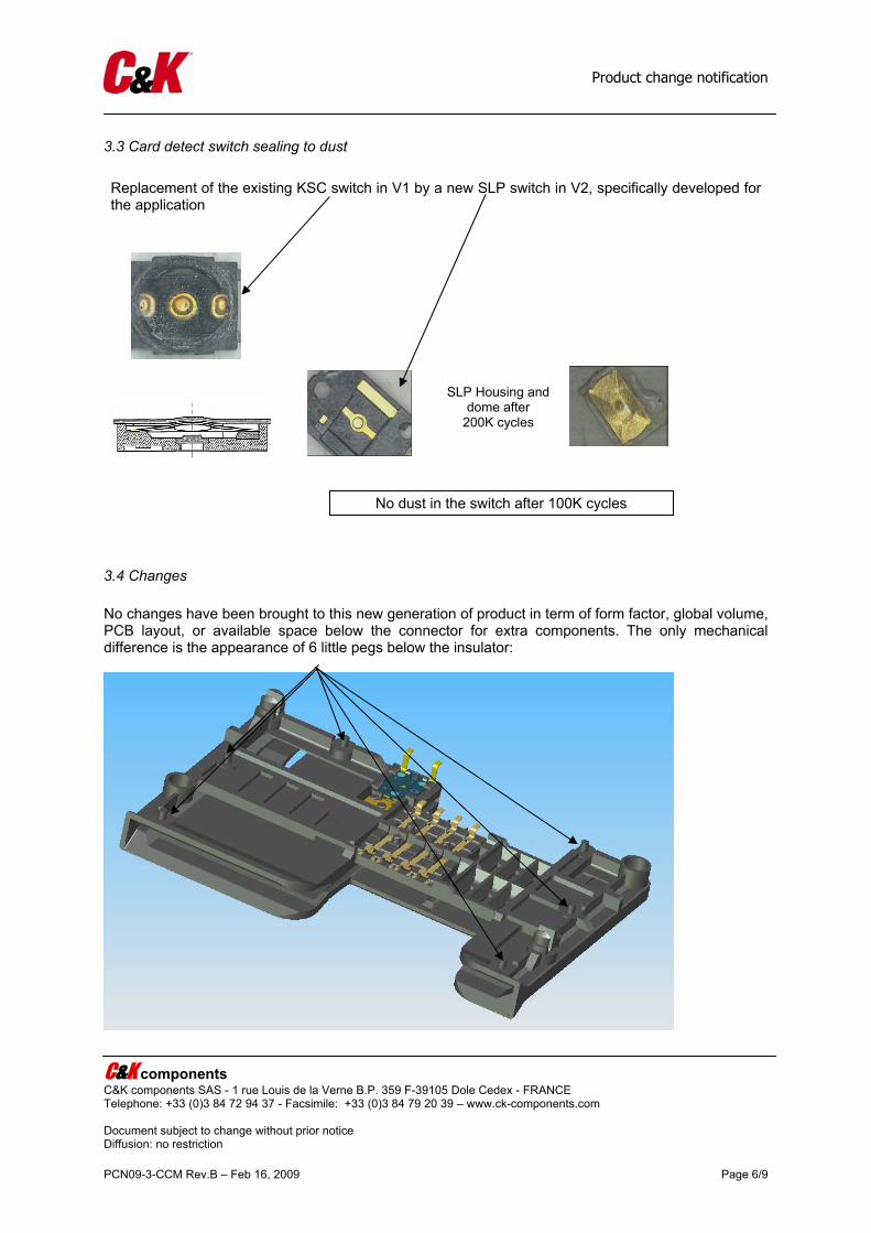
3.3 Card detect switch sealing to dust
3.4 Changes No changes have been brought to this new generation of product in term of form factor, global volume, PCB layout, or available space below the connector for extra components. The only mechanical difference is the appearance of 6 little pegs below the insulator:
Replacement of the existing KSC switch in V1 by a new SLP switch in V2, specifically developed for the application
No dust in the switch after 100K cycles
SLP Housing anddome after
200K cycles

Product change notification
C&K components C&K components SAS - 1 rue Louis de la Verne B.P. 359 F-39105 Dole Cedex - FRANCE Telephone: +33 (0)3 84 72 94 37 - Facsimile: +33 (0)3 84 79 20 39 – www.ck-components.com Document subject to change without prior notice Diffusion: no restriction PCN09-3-CCM Rev.B – Feb 16, 2009 Page 7/9
The pegs are necessary for the optional APS cover protection as shown on the figure below:
4. Application
4.1 Overview
Since products are fully compatible and respect the same specifications, the change over from one version to the new product can be easily done, finishing existing stock in the supply chain and replace it by the new version.
4.2 Product range affected
All CCM01 MK2 except version with 4 clips (see annex 1)
4.3 Date of application & time frame
Samples availability: available Last time buy: June 15th 2009 with deliveries in the following two (2) month Discontinuation of old version and application date for new version: July 15th 2009
Note: C&K will apply the change on any P/N prior to the application date in the case of the entire necessary customer approval will be received. The corresponding information will be forwarded on time through our customer service network.
4.4 Ordering, pricing and stock handling policy
Ordering: P/N codes as per table on annex 1. Pricing: any pricing and other sales conditions remain valid. Stock handling: no obsolescence and no specification modification is applied on any P/N. No return or scrap for obsolescence will be accepted.
Product change notification
C&K components C&K components SAS - 1 rue Louis de la Verne B.P. 359 F-39105 Dole Cedex - FRANCE Telephone: +33 (0)3 84 72 94 37 - Facsimile: +33 (0)3 84 79 20 39 – www.ck-components.com Document subject to change without prior notice Diffusion: no restriction PCN09-3-CCM Rev.B – Feb 16, 2009 Page 8/9
4.5 Customer qualification We recommend to our customers to carry on the necessary actions and qualifications they feel necessary to make sure that they will be ready at the date of application. We haven’t modified the product features to minimize the customer impact and make easier the modification acceptation. For any reason, if you evaluate that your acceptation will be released after the date of application, you have to notify C&K components at least 1 month before the application date, ie May 15th 2009. Without this notification, the change will be applied on any purchased products affected by the modification. As no material modification is done, the IMDS data remain unchanged.
5 Acknowledgement We recommend acknowledging this PCN with your requirements in terms of samples & qualification files no later than March 15th 2009 at the following email address: [email protected].
6 Support For any question, please contact Fabrice Valcher at the above email address

Product change notification
C&K components C&K components SAS - 1 rue Louis de la Verne B.P. 359 F-39105 Dole Cedex - FRANCE Telephone: +33 (0)3 84 72 94 37 - Facsimile: +33 (0)3 84 79 20 39 – www.ck-components.com Document subject to change without prior notice Diffusion: no restriction PCN09-3-CCM Rev.B – Feb 16, 2009 Page 9/9
ANNEX 1 OLD VERSION NEW VERSION CCM01-2251 LFT T30/ 8 contacts SMT with 2 locating pegs CCM01-2013AP LFT T30/ CCM01-2252 LFT T30/ 16 contacts SMT with 2 locating pegs No replacement CCM01-2253 LFT T30/ 8 contacts SMT with 2 locating pegs CCM01-2013AP LFT T30/ CCM01-2254 LFT T30/ 16 contacts SMT with 2 locating pegs No replacement CCM01-2255 LFT T30/ 8 contacts through hole with 2 locating pegs CCM01-2012AP LFT T30/ CCM01-2256 LFT T30/ 16 contacts through hole with 2 locating pegs No replacement CCM01-2270 LFT T30/ 8 contacts through hole no brake CCM01-2112AP LFT T30/
with 2 locating pegs (drawing under revision) Please note that CCM01-2065 and CCM01-2069 are not discontinued yet. 16 contacts version can be replaced by 8 contacts version. Drawings and specifications of new version can be found on the next pages.

PRODUCT SPECIFICATION CCM01-MKII V2 - LFT Ref. / PS-CCM01-MKII- 2 Page 1 / 8
ISSUE 1 – Rev. G: SEPTEMBER 2008
Approvals: ________________________________________________ Laurent Kubat Date Engineering Manager ________________________________________________ Guillaume Pinon Project Manager ________________________________________________ Daniel Pequegnot Laboratory Manager ________________________________________________ Jerome Smolinski Product Manager ________________________________________________ Jérome Brochot Quality Director ________________________________________________ Note
This specification, attached documents and attached drawings cannot be communicated to anybody without written agreement of C&K.

PRODUCT SPECIFICATION September 2008
CCM01-MKII V2-LFT Issue 1-rev.G
Ref. / PS-CCM01-MKII-2 Page 2 / 8
Revision record:
Revision Date Comments Issue 1 April 25th , 2005 Creation
Issue 1 – Rev. A Sept. 29th , 2005 Update : • Card end travel switch : dust sealed • Soldering processes : recommendation for
solder thickness • Marking resistance
(According to DCR N°D2000398) Issue 1 – Rev. B March 28th , 2006 Update :
• Tab page 4 : Versions covered by this spec. • Option : I/O Protect diagram added (page 4) • §10 “Additional data” added (According to ECR -327)
Issue 1 – Rev. C June 19th , 2006 Update : • Tab page 4 : Reinforced versions added • Static load test updated - § 7 • Metallic peg retention test added - § 7 • Operating Life test updated - § 8 (According to ECR -515)
Issue 1 – Rev. D January 12th , 2007 Update : • Operating environment : Operating life –
Recommendation updated • Additional data : Automatic assembly – Pick
& Place note added. (According to ECR -742)
Issue 1 – Rev. E August 8th , 2007 Update : • Solder heat resistance : 10s instead of 5s
(LF version) • Resistance to fluids : comment added (according to ECR 1186)
Issue 1 – Rev. F October 2nd , 2007 Update : • Recommendations of use added (§ 2). (according to ECR 1429)
Issue 1 – Rev. G September 8th , 2008 Update : • UL data suppressed (according to ECR 2324) • Reference of test specifications updated (according to ECR 2446)

PRODUCT SPECIFICATION September 2008
CCM01-MKII V2-LFT Issue 1-rev.G
Ref. / PS-CCM01-MKII-2 Page 3 / 8
SUMMARY Preliminary / versions covered by this specification 1. Description 2. Recommendation of use 3. Physical data
4. Using temperatures
5. Electrical data 6. Mechanical data 7. Storage and handling environment 8. Process environment 9. Operating environment 10. Applicable norms 11. Additional Data 12. Qualification Plan
PRODUCT SPECIFICATION September 2008
CCM01-MKII V2-LFT Issue 1-rev.G
Ref. / PS-CCM01-MKII-2 Page 4 / 8
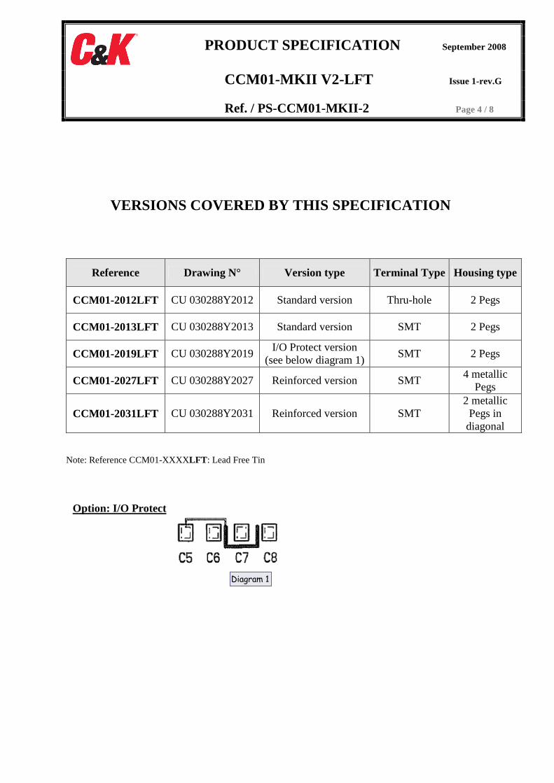
VERSIONS COVERED BY THIS SPECIFICATION
Reference Drawing N° Version type Terminal Type Housing type
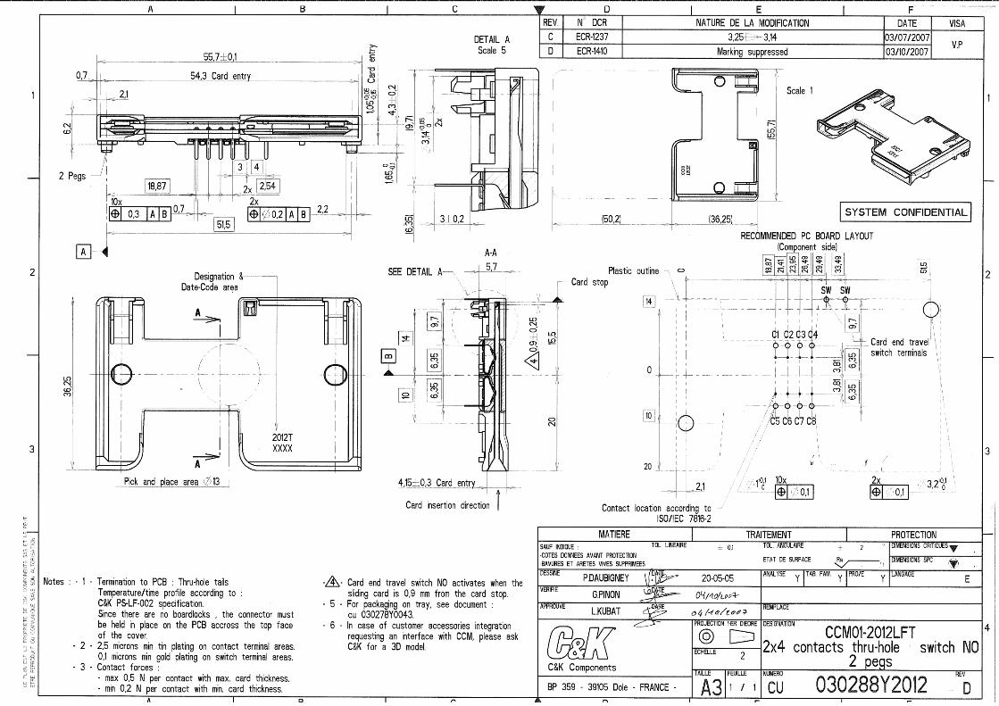
CCM01-2012LFT CU 030288Y2012 Standard version Thru-hole 2 Pegs
CCM01-2013LFT CU 030288Y2013 Standard version SMT 2 Pegs
CCM01-2019LFT CU 030288Y2019 I/O Protect version
(see below diagram 1) SMT 2 Pegs
CCM01-2027LFT CU 030288Y2027 Reinforced version SMT 4 metallic
Pegs
CCM01-2031LFT CU 030288Y2031 Reinforced version SMT 2 metallic Pegs in diagonal
Note: Reference CCM01-XXXXLFT : Lead Free Tin
Option: I/O Protect
Diagram 1

PRODUCT SPECIFICATION September 2008
CCM01-MKII V2-LFT Issue 1-rev.G
Ref. / PS-CCM01-MKII-2 Page 5 / 8
1 - Description 2 – Recommendations of use
According to C&K recommendations: RU-CCM-001 document
3 – Physical data
Mass 5.0 g ± 1.0
Dimensions & lay out According to drawing : see table page 4
4 – Using temperatures
Operating temperatures - 40 °C / + 85 °C
Storage temperatures - 40 °C / + 85 °C
Soldering temperature According to IEC 61760-1 :2006
5 - Electrical data
Voltage / ct ≤ 5 Vdc
Current / ct ≤ 10 Ma Contact resistance ≤ 100 mΩ Voltage proof ≥ 750 Vrms
Insulation resistance Initial measurement ≥ 1000 MΩ (100 VDC) After damp heat ≥ 1 MΩ recovery time : 4 hours
After damp heat ≥ 200 MΩ recovery time : 24 hours Card end travel switch characteristics : - Max power
0.2 VA
- Max voltage
30 Vdc - Min/Max current 50 µA min / 10 mA max - Bounces ≤ 3 ms - Voltage proof ≥ 750Vrms between signal contact / switch contacts
≥ 250Vrms between open contacts of the switch - Insulation resistance Initial measurement ≥ 1000 MΩ (100 VDC)
After damp heat ≥ 1 MΩ recovery time : 4 hours
After damp heat ≥ 200 MΩ recovery time : 24 hours between signal contact / switch contacts & between open contacts of the switch
- Contact resistance ≤ 100 mΩ Card end travel switch sequence According to drawing : see table page 4
6 – Mechanical data
Card insertion force 10 N max
Card withdrawal force 1 N min / 10 N max
Contact force (signal contact) According to drawing : see table page 4
Contact force (end travel switch) 0.8 N max to activate the switch 1.8 N max for complete actuator depression
Snap-in force (version with clips) 10 N min / 50 N max
Snap-off force (version with clips) 10 N min
7 - Storage and handling environment
Marking & Traceability Designation : 20xxT (for CCM01-20xxLFT) Date code : year / week / day
Packaging conditions According to drawing : CU 030278Y0043
Product group : CCM01 Product Sub Family : Mk2 Card type : Full-sized card Contact type : Friction Contact plating : Precious metal inlay Contacts number : 8 Terminal type : SMT or thru-hole see table page 4 Card end travel switch : Switch NO: Normally Open Dust sealed switch Housing type : see table page 4 Generic specification (C&K) : Proc. essai 20
Transport conditions Sea-air-land / World wide / High ≤ 5 m 30°C / 85% HR According to H00-060

PRODUCT SPECIFICATION September 2008
CCM01-MKII V2-LFT Issue 1-rev.G
Ref. / PS-CCM01-MKII-2 Page 6 / 8
8 - Process environment Soldering processes : • Lead free reflow soldering
process (SMT terminals)
• Lead Free single or double wave soldering process (through Hole Terminals)
• According to IEC 61760-1:2006 Recommendation for solder paste thickness : ≥ 0.20 mm
• According to IEC 61760-1:2006
Solder heat resistance 3 cycles at max profile according to IEC 61760-1:2006 According to IEC 60068-2-58
Static load (transverse) (CCM / PCB)
10 N / 1 mn / 4 directions (standard version) 40 N / 1 mn / 4 directions (reinforced version) According to IEC 512-5 test 8a/8b
Terminal robustness 1 bend / 45° / forward & back According to IEC 60068-2-21 test Ub method 1
Contact retention in insert 2 N / 10sec./ displacement < 0.3 mm According to IEC 512-8 test 15a
Metallic peg retention in housing Reinforced version ≥ 30 N (lateral & axial directions)
Solderability (wetting balance) 245°C According to IEC 60068-2-69
Dust sealed test (only for switch) Dust test / IP5x According to IEC 60529:1989/A1:1999
Resistance to fluids The product is not compatible with washing process.
9 – Operating environment
Operating life
≥ 100 000 cycles • at 10 N force for standard version • at 40 N force for reinforced version
Recommendation: 4 metal pegs. Other configurations are possible, according to customer integration.
Vibration 10-500 Hz / 50 m/s² / 3 axis / 2 hours per axis No discontinuity > 1 µs According to IEC 60068-2-6.
Mechanical shock
500 m/s² / ½ sinusoidal / 11 ms 3 shocks in the 2 directions of the 3 axis No discontinuity > 1 µs According to IEC 60068-2-27.
Rapid change of temperature 100 cycles / - 40°C / + 85°C According to IEC60068-2-14, test Nb
Climatic sequence
Dry heat : 85°C / 16 hours Damp heat : 1 cycle 24 hours 55°C & 93% HR Cold : – 40°C / 2 hours Damp heat : 1 cycle 24 hours 55°C & 93% HR According to IEC 60068-2-61, test Z/ABDM
Dry heat storage 85°C / 250 hours According to IEC 60068-2-2 , test Bb.
PRODUCT SPECIFICATION September 2008
CCM01-MKII V2-LFT Issue 1-rev.G
Ref. / PS-CCM01-MKII-2 Page 7 / 8
Damp heat storage 40°C / 93% HR / 10 days According to IEC 60068-2-78 test Cab
Corrosion 96 hours / salt spray According to IEC 60068-2-11, test Ka.
The environmental tests can be cumulative according to the qualification file
10 - Applicable norms Legal norm (EHS) C&K procedure
Warranty period 1 year
11- Additional data
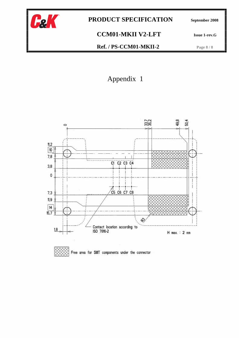
Free space under CCM According to appendix 1
Automatic assembly - Pick & Place
Increase the diameter of holes on PCB to 3.4 mm ± 0.05 to use standard version (plastic pegs). However this assembly is not recommended. The best global life test performance will be achieved by using reinforced version (metal pegs), as mentioned above, see § 8,Operating life – recommendation (40 N insertion).
12- Qualification Plan
According to Proc-20
PRODUCT SPECIFICATION September 2008
CCM01-MKII V2-LFT Issue 1-rev.G
Ref. / PS-CCM01-MKII-2 Page 8 / 8
Appendix 1