Product Catalogue -...
44
Product Catalogue
Transcript of Product Catalogue -...

Product Catalogue

www.phsvesis.com

3
Limitation of liabilityIt is mandatory, PH Svesis products to be installed in accordance with the manuals, applicable codes, and the in-structions of the Authority Having Jurisdiction. The manufacturer shall not under any circumstances be liable for any incidental or consequential damages arising from loss of property or other damages or losses owing to the failure of products beyond the cost of repair or replacement of any defective products. The manufacturer reserves the right to make product improvements and change product specifications at any time.The manufacturer assumes no responsibility for errors or omissions, while every precaution has been taken during the preparation of the manuals to ensure the accuracy of their contents.
WarrantyPH Svesis warrants its products to be free from defects in materials and workmanship under normal use for a period of two (2) years (the “Warranty Period”) from the delivery date referring to Invoices, identified by Production Date code(s) indicated on the products. Because PH Svesis does not install the products and because the products may be used in conjunction with products not manufactured by PH Svesis, PH Svesis cannot guarantee the performance of the products and shall not be responsible in any way whatsoever for faulty installation or connection.
RoHS directive complianceThe EC RoHS guideline has been released in order to reduce the heavy metal load in electrical and elec-tronic products caused by e.g. lead and mercury. All manufacturers are obligated to provide only RoHS-compliant products to the European market, effective from July 1st, 2006.PH Svesis hereby states that all products are fully compliant with RoHS 2002/95/EC directive.
Disposal of your old appliance1. When this crossed-out wheeled bin symbol is attached to a product it means the product is covered by the European Directive 2002/96/EC.2. All electrical and electronic products should be disposed of separately from the municipal waste stream via designated collection facilities appointed by the government or the local authorities.3. The correct disposal of your old appliance will help prevent potential negative consequences for the envi-ronment and human health.4. For more detailed information about disposal of your old appliance, please contact your city office, waste disposal service or the shop where you purchased the product.
importantInformation

4
Paradox Hellas S.A. was founded on January 1990 and has established itself as the leading company in the Greek market in terms of import and wholesale distributor of Burglar Alarm, Fire Detection, CCTV and Access Control systems. Since 2003 it invested on design develop and manufacture Fire alarm panels, accessories for security systems such as outdoor sirens, GSM back up communication modules, IP communication modules etc.In 2017, Paradox Hellas Exports department was formed into a new company; PH Svesis.PH Svesis distributes Fire Alarm and Fire Extinguishing products as well as a full range of related accessories and peripherals.Product lines are available in the Greek market but, most importantly, exported to more than 20 countries worldwide, such as Hungary, Romania, Spain, Turkey, United Arab Emirates, Lebanon, Jordan, Nigeria, South Africa, Iran and India.PH Svesis’ HQ and fully automated robotic assembly lines are situated in the state of the art, fully owned production facilities of 2000 square meters, located at the 69th kilometer of Athens-Lamia national road.Production facilities hold an active authorization to mark LPCB and CPR products with quarter-annual and annual planned certification programs from LPCB and EVPU respectively. All prod-ucts are assembled and comply with the ROHS 2002/95/EC directive making them eligible for selling to any European Community country.PH Svesis holds an active ISO9001:2008 certificate for distribution. PARADOX HELLAS S.A. holds an active ISO9001:2008 certificate for the whole of its activities (operation, wholesale, sup-port, design, manufacturing).The company strives to develop and maintain long lasting business relationships with its partners. Keeping close to them and appreciating their valuable feedback, pushes the company to improve and expand constantly.PH Svesis’ philosophy is “products of the highest quality with services and support to match; all at competitive prices”.
About

5
Certificates
■ Matrix2000 is EN 54-2 & EN 54-4 certified from EVPU a.s. ■ Fighter & Fighter XT are EN 54-2, EN 54-4 & EN 12094-1 certified
from EVPU a.s. ■ SmartX are EN 54-2 & EN 54-4 certified from LPCB and CE certified
from EVPU a.s. ■ SmartX Hochiki ESP compliance certificate. ■ NEON id EN 54-2 & EN 54-4 certified from EVPU a.s. ■ SIR/PLL & SIR/V are EN 50131-4 (Security Grade 3, Environmental
Class IV) certified from EVPU a.s. ■ ARCO, ELIX & EXIDUS are ENEC approved and certified to
EN60598 from EVPU a.s. ■ Sirion is CE certified from EMC Hellas. ■ BUREAU VERITAS ISO 9001:2008. No GR17.3073Q in distribution.
Matrix2000 Fighter Fighter XT
SIR/PLL SIR/V SirionArco, Elix & Exidus
SmartX Neon
Company
Fire Alarm Systems

7
General Specifications ■ One Loop Addressable fire alarm control panels. ■ 2 Conventional Zones (Maximum 20 detectors per zone). ■ Day/Night operation, separate profile for each week day. ■ Manual add/remove of loop devices. ■ 2 Supervised Siren Outputs. ■ 2 Logical Inputs. ■ 2 Supervised Relay Outputs. ■ Storage of up to 2,000 log events. ■ Built-in communicator (Ademco Contact ID). ■ System LED indications: Power, Fault, Alarm, Pre Alarm, Delay Active, Sirens Silenced, On Test. ■ WalkTest installation testing feature. ■ Customisable weekly reminder for system test. ■ Real time clock. ■ Remote software monitoring and programming.
Technical SpecificationsNumber of loops 1Loop current 500mA (Hochiki), 400mA (Apollo)Fire zones / Zonal indicators 16 (smartX 116), 32 (smartX 132)Conventional zones 2 (Maximum 20 detectors per zone)Conventional zones termination resistors 4,7Κ Ohms / 1WSupervised siren outputs 2 outputs, 24VDC ±10%, 1A max, fused and monitored
Generic trouble output (on main unit) non monitored Dry relay contacts NO - C - NC
Analogue Inputs 2 intern AUX pulled up inputs 1.5mA sinc current
Relay Outputs 2 general relay outputsN/O or N/C (jumper selectable) dry contacts 28V/3A max
PGM Outputs 4 PGM outputsOpen collector, 200mA sink max current, 30V max handling
Earth faults detection and indication Front panel LCD indication & buzzerDisplay 4 lines of 20 characters LCDMains Power 220 VAC 50HzMains supply fuse 1,6A 250Power Supply 24 VDC / 2.5AAUX output 24VDC +/- 10%, 700mA max, current limited, monitoredBattery Backup power 2x 12V / 7Ah sealed lead acid gel batteriesBattery health monitoring (periodic load test) Every 90 secondsEnclosure Epoxy powder coated metal boxDimensions (HxWxD)[mm] 315 x 425 x 100IP rating IP30
ESP
S90
DiscoveryXP95
single loop addressable fire alarm control panels
EC Certificate Number00123/101/1/20160832-CPR-F1616
Cert No. 1369a/01

8
The SmartX fire panels offer: ■ PSTN communicator for remote reporting of events. ■ LOG event registry, up to 2000 events. ■ Bypasses (disablements) for inputs and outputs. ■ Delayed outputs, Alarm verification for all inputs. ■ Global evacuation triggered by any input, selectable at Access Level 3. ■ Periodic test reminder. ■ Walk test: An easy way to test the system by triggering one input at the time. ■ TCP/IP expansion port provides remote monitoring and control with optional TCP/IP module. ■ PC connectivity: The expansion port along with the required communication module permits PC
connectivity for system supervision and operations. ■ Direct activation of outputs from inputs regardless of alarm/evacuation state programmed at A.L.3. ■ Group operations change specific attributes in groups of objects, making programming much more
efficient. ■ Autolearn function for loop devices. ■ Backup/Restore configuration; Save current system configuration to on-board memory and restore
it if needed. ■ Real time clock/calendar with battery backup. ■ Optional eight, 24V output, monitored relay expansion module with 3A power supply and battery
power backup (also fully monitored). ■ Easy device identification through their LED indicators. ■ Easy contamination levels/sensor health checks with device identification. ■ Delayed group activation for cascaded evacuation schemes. ■ Easy configurable inverse operation of outputs for high safety applications (e.g. fire doors). ■ Programmable activation of outputs on faults/bypasses (required for fire doors in some locales). ■ Easy identification of contaminated sensors with simultaneous LED activation on all troubled
devices. ■ User friendly interface: List based presentation with cursor keys navigation, filters and formatting of
viewable information. ■ On screen, context intelligent short help. ■ User defined descriptions for all inputs, outputs and zones. ■ Advanced Access level control: The system is not limited to the required by European and
American standard. ■ 3 access levels: It provides 8 Access Level 2 users plus one Master user that manages the rest.
There is also the Access Level 3 user (installer) and an access codes reset mechanism. ■ Main screen branding, Installer’s contact info: The installer has one line (20 characters) on the
main screen that can program to display any message he wishes (e.g. company name). Contact information (e.g. telephone number) may also be programmed into the panel for user reference.
■ Convenient loop devices overview with alarms, faults and installed types indications. ■ Visual overview of installed loop devices.
single loop addressable fire alarm control panels

9
SMARTX 116 - S90, XP95, DISCOVERY
Single Loop Addressable panel (16 Zonal Indicators) Single Loop Analogue Addressable control panels, based on Apollo’s S90, XP95 & Discov-ery protocols. Zonal Indicators: 16. Fire Zones: 16. 2 Conventional Zones. Maximum num-ber of detectors per zone 20. 2 Supervised Siren Outputs. 2 Logical Inputs. 2 Supervised Relay Outputs. Storage of up to 2,000 log events. Built-in communicator.Order Code: PH.SA.116.EN
SMARTX 132 - S90, XP95, DISCOVERY
Single Loop Addressable panel (32 Zonal Indicators)Single Loop Analogue Addressable control panels, based on Apollo’s S90, XP95 & Discov-ery protocols Zonal Indicators: 32. Fire Zones: 32. 2 Conventional Zones. Maximum num-ber of detectors per zone 20. 2 Supervised Siren Outputs. 2 Logical Inputs. 2 Supervised Relay Outputs. Storage of up to 2,000 log events. Built-in communicator.Order Code: PH.SA.132.EN
SMARTX 116 - ESP
Single Loop Addressable panel (16 Zonal Indicators) ESP Single Loop Analogue Addressable control panels. Zonal Indicators: 16. Fire Zones: 16. 2 Conventional Zones. Maximum number of detectors per zone 20. 2 Supervised Siren Outputs. 2 Logical Inputs. 2 Supervised Relay Outputs. Storage of up to 2,000 log events. Built-in communicator.Order Code: PH.SH.116.EN
SMARTX 132 - ESP
Single Loop Addressable panel (32 Zonal Indicators)ESP Single Loop Analogue Addressable control panels. Zonal Indicators: 32. Fire Zones: 32. 2 Conventional Zones. Maximum number of detectors per zone 20. 2 Supervised Siren Outputs. 2 Logical Inputs. 2 Supervised Relay Outputs. Storage of up to 2,000 log events. Built-in communicator.Order Code: PH.SH.132.EN
SMARTX KSDA
Keypad/Repeater - S90, XP95 & DISCOVERY ■ LCD display with silicon rubber keypad. ■ Repeater for Access Level 1 & 2. ■ Dimensions (HxWxD [mm]): 110 x 155 x 25.
Order Code: PH.KP.SMΑ.EN
Keypad/Repeater - ESP ■ LCD display with silicon rubber keypad. ■ Repeater for Access Level 1 & 2. ■ Dimensions (HxWxD [mm]): 110 x 155 x 25.
Order Code: PH.KP.SMH.EN
single loop addressable fire alarm control panels
10
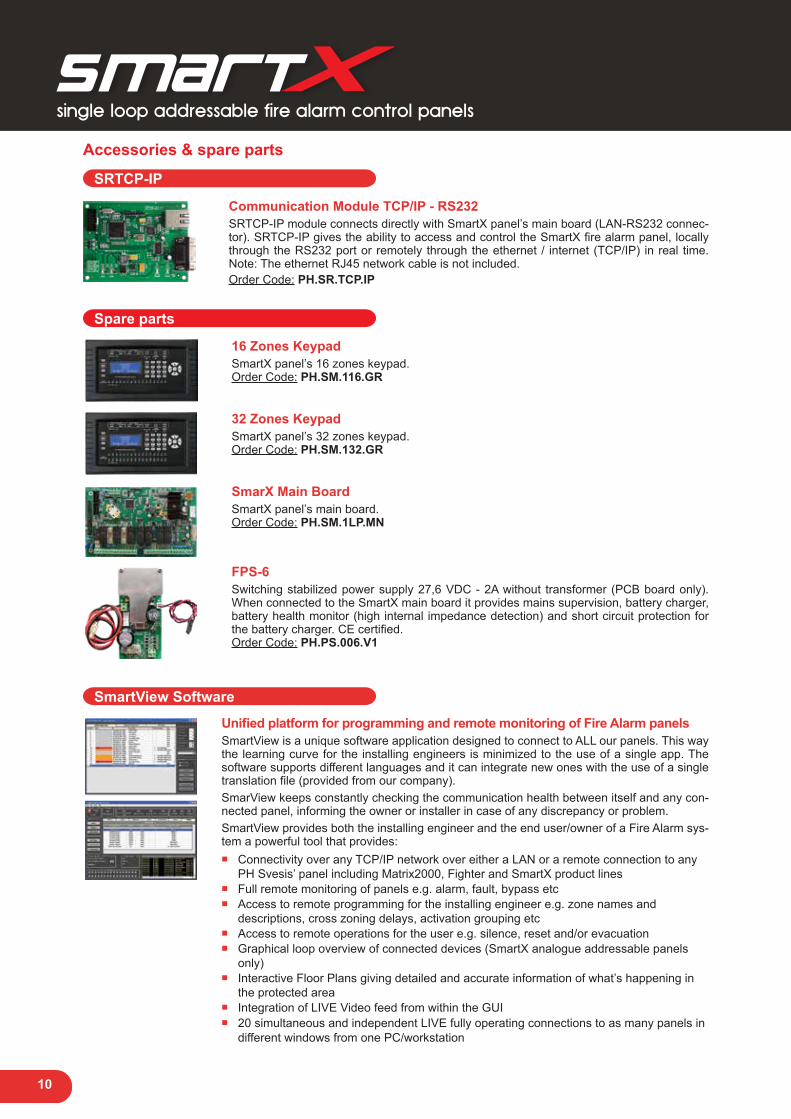
Accessories & spare parts
SRTCP-IP
Communication Module TCP/IP - RS232SRTCP-IP module connects directly with SmartX panel’s main board (LAN-RS232 connec-tor). SRTCP-IP gives the ability to access and control the SmartX fire alarm panel, locally through the RS232 port or remotely through the ethernet / internet (TCP/IP) in real time. Note: The ethernet RJ45 network cable is not included.Order Code: PH.SR.TCP.IP
Spare parts
16 Zones Keypad SmartX panel’s 16 zones keypad.Order Code: PH.SM.116.GR
32 Zones Keypad SmartX panel’s 32 zones keypad.Order Code: PH.SM.132.GR
SmarX Main Board SmartX panel’s main board.Order Code: PH.SM.1LP.MN
FPS-6 Switching stabilized power supply 27,6 VDC - 2A without transformer (PCB board only). When connected to the SmartX main board it provides mains supervision, battery charger, battery health monitor (high internal impedance detection) and short circuit protection for the battery charger. CE certified.Order Code: PH.PS.006.V1
SmartView Software
Unified platform for programming and remote monitoring of Fire Alarm panelsSmartView is a unique software application designed to connect to ALL our panels. This way the learning curve for the installing engineers is minimized to the use of a single app. The software supports different languages and it can integrate new ones with the use of a single translation file (provided from our company).SmarView keeps constantly checking the communication health between itself and any con-nected panel, informing the owner or installer in case of any discrepancy or problem.SmartView provides both the installing engineer and the end user/owner of a Fire Alarm sys-tem a powerful tool that provides:
■ Connectivity over any TCP/IP network over either a LAN or a remote connection to any PH Svesis’ panel including Matrix2000, Fighter and SmartX product lines
■ Full remote monitoring of panels e.g. alarm, fault, bypass etc ■ Access to remote programming for the installing engineer e.g. zone names and
descriptions, cross zoning delays, activation grouping etc ■ Access to remote operations for the user e.g. silence, reset and/or evacuation ■ Graphical loop overview of connected devices (SmartX analogue addressable panels
only) ■ Interactive Floor Plans giving detailed and accurate information of what’s happening in
the protected area ■ Integration of LIVE Video feed from within the GUI ■ 20 simultaneous and independent LIVE fully operating connections to as many panels in
different windows from one PC/workstation
single loop addressable fire alarm control panels
11
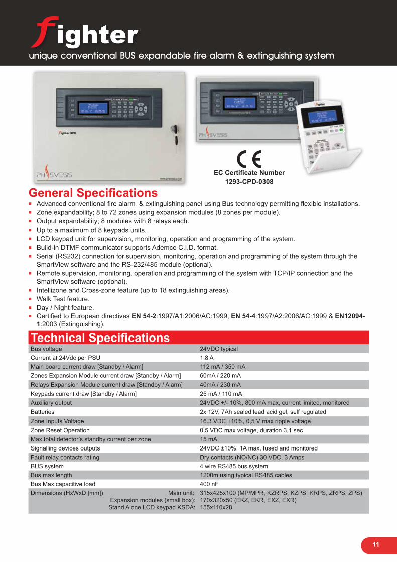
General Specifications ■ Advanced conventional fire alarm & extinguishing panel using Bus technology permitting flexible installations. ■ Zone expandability; 8 to 72 zones using expansion modules (8 zones per module). ■ Output expandability; 8 modules with 8 relays each. ■ Up to a maximum of 8 keypads units. ■ LCD keypad unit for supervision, monitoring, operation and programming of the system. ■ Build-in DTMF communicator supports Ademco C.I.D. format. ■ Serial (RS232) connection for supervision, monitoring, operation and programming of the system through the
SmartView software and the RS-232/485 module (optional). ■ Remote supervision, monitoring, operation and programming of the system with TCP/IP connection and the
SmartView software (optional). ■ Intellizone and Cross-zone feature (up to 18 extinguishing areas). ■ Walk Test feature. ■ Day / Night feature. ■ Certified to European directives ΕΝ 54-2:1997/Α1:2006/AC:1999, ΕΝ 54-4:1997/Α2:2006/AC:1999 & ΕΝ12094-
1:2003 (Extinguishing).
Technical SpecificationsBus voltage 24VDC typicalCurrent at 24Vdc per PSU 1.8 AMain board current draw [Standby / Alarm] 112 mA / 350 mAZones Expansion Module current draw [Standby / Alarm] 60mA / 220 mARelays Expansion Module current draw [Standby / Alarm] 40mA / 230 mAKeypads current draw [Standby / Alarm] 25 mA / 110 mAAuxiliary output 24VDC +/- 10%, 800 mA max, current limited, monitoredBatteries 2x 12V, 7Ah sealed lead acid gel, self regulatedZone Inputs Voltage 16.3 VDC ±10%, 0,5 V max ripple voltageZone Reset Operation 0,5 VDC max voltage, duration 3,1 secMax total detector’s standby current per zone 15 mASignalling devices outputs 24VDC ±10%, 1A max, fused and monitoredFault relay contacts rating Dry contacts (NO/NC) 30 VDC, 3 AmpsBUS system 4 wire RS485 bus systemBus max length 1200m using typical RS485 cablesBus Max capacitive load 400 nFDimensions (HxWxD [mm]) Main unit:
Expansion modules (small box):Stand Alone LCD keypad KSDA:
315x425x100 (MP/MPR, KZRPS, KZPS, KRPS, ZRPS, ZPS)170x320x50 (EKZ, EKR, EXZ, EXR)155x110x28
EC Certificate Number1293-CPD-0308
unique conventional BUS expandable fire alarm & extinguishing system

12
BUS 4854-wire
Maximumdistance
1200 meters
Fighter MP / Fighter MPR FRTCP-IP RS-232PSTN
TCP-IP
Fighter KRPS
Fighter KSDA
8 zones Fighter panel withor without 8 relay outputs
TCP-IP/RS-232 module
8 relays expansion panelwirh keypad and PSU
Fighter 8 zones expansionpanel with 8 relay outputs
with keypad and PSU
Fighter 8 zones expansionpanel with keypad
Fighter 8 zones expansion panelwithout keypad
Fıghterstand alone keypad
Fighter ZPS
8 zones expansion panelwith PSU, without keypad
Fighter KSDA
Fighter KZRPS
Fighter EXZ
Fighter EKZ
Fighterstand alone keypad
Fighter KSDA
Fighterstand alone keypad
Fighter 8 relay outputs expansion panelwithout keypad
Fighter EXR
Full Fighter System SetupThe maximum Fighter system setup may include:- 8 modules of zones expansion- 9 modules of relays expansion: 8 + 1 relay expansion module of the Fighter Main Panel- 9 keypads: 1 Fighter MP keypad and 8 keypads selectable through Fighter KSDA and “on panel” keypads.- Up to 16 PSUs (Power Supply Unit): 1PSU per zones expansion module and/or relay outputs expansion module
Central MonitoringStation
LAN/WAN
Phone LineProvider
Fighter ProVision
SmartView
unique conventional BUS expandable fire alarm & extinguishing system

13
The Fighter system offers: ■ Menu driven conventional fire alarm and extinguishing panel using 4-wire Bus technology.
Expandability over RS-485, permitting flexible and cost optimized installations. ■ Zones expandability: 8 to 72 analogue conventional detector inputs, using modules interconnected
with 4-wire BUS. 8 zones per module. ■ Cross-zoning/extinguishing operation: Up to 18 extinguishing areas with the full system setup.
The system uses 4 zones and 4 relays to produce a very reliable alarm detection and commence a sequence of relay activations. Mainly used to drive extinguishing systems. Any group of 4 zones on any module along with their corresponding relays may be programmed as an extinguishing area.
■ Outputs expandability: 8 to 72 relays using modules interconnected with 4-wire BUS. 8 monitored relays per module. Relay boards with one relay dedicated to each zone input: Each zone input is mirrored by a relay. When the zone is in alarm the relay is active producing 24 VDC.
■ LCD keypad units for supervision, monitoring, operation and programming of the system Multiple display/keyboard units (as repeaters): Up to 8 extra keypad units may be connected to the BUS. The system ensures correct inter-operation and implements a lock out mechanism if one keypad unit enters an elevated access level (2 or 3). The keypads have 4x20 alphanumeric LCD, and backlit ruler keys. Embedded help system provides vital in system information.
■ Two general alarm siren relay outputs 24VDC/1A max (monitored): The two siren outputs get activated when an alarm condition is detected. The first of the two relays produce a constant output when active. The second can be programmed to produce an output pattern (e.g. ANSI evacuation pattern).
■ 1 main general fault output (not monitored): Dry contact relay 3A max. Gets activated when any fault condition is detected.
■ Power supply expansion: Up to 16 fully supervised power supply units (PSU) may be connected on expansion modules. The system is fully monitoring the AC supply, battery connections and health of each connected power supply. Power supplies are EN54-4 certified.
■ Built in communicator: A PSTN line interface provides communication of events to a Central Monitoring Station. The communication format used is Contact ID.
■ Automatic module detection upon installation (relay, zones and keypad modules). ■ Easy module identification: Modules are easily identified with a selection mechanism from the
keypad units and their status LED (selecting a module of interest will activate a specific blinking pattern on the selected module).
■ Bypasses (disablements) for both zone inputs and relay outputs: Zone inputs and Relay outputs may be disabled independently from each other.
■ Intellizone operation (Alarm verification): A system that provides a verification to an alarm condition before the alarm state is entered. Helps avoid false alarms by combining alarm signals in time and/or from different detector zones. Can be activated on selected zones and may have global or per module grouping.
■ Day/Night operation: A system that reduces false alarms during specific hours of the day by using the intellizone feature. Used for example in smoking areas during working hours.
■ 3 options for global evacuation: The system can use manual call points or/and a key combination on the keypads or/and extinguish zones to activate the global evacuation condition.
■ Walk Test feature: The user may activate a test state on the panel. During the test he manually triggers each one detector and the system once the alarm is detected sounds the sirens for a short period and auto resets. He/she then repeats the triggering process for all detectors to verify the system’s good operation.
■ LOG (events): Storage of up to 1,000 log events. ■ Serial (RS232) connection for supervision, monitoring, operation and programming of the system
through the ProVision software and the FRS-232 module (optional). ■ Remote supervision, monitoring, operation and programming of the system with FRTCP/IP
(optional TCP/IP module) connection and the SmartView software (optional). ■ Certified to European directives ΕΝ 54-2:1997/Α1:2006/AC:1999, ΕΝ 54-4:1997/Α2:2006/AC:1999 &
ΕΝ 12094-1:2003 (Extinguishing). EC - Certificate of Conformity No. 123-CPD-0308 of July 2, 2012.
unique conventional BUS expandable fire alarm & extinguishing system

14
unique conventional BUS expandable fire alarm & extinguishing system
Fighter MP
8 zones conventional fire alarm panel Expandable up to 72 zones using expansion modules (8 zones per module). Output ex-pandability; up to 8 relay modules with 8 relays each. Up to a maximum of 8 keypads units per system. Built in communicator supporting Contact I.D protocol. Power supply 27.6 VDC, 2A. CE certified.Order Code: PH.PL.FIT.08
Fighter MPR
8 zones and 8 relays conventional fire alarm & extinguishing panelExpandable up to 72 zones using expansion modules (8 zones per module). Output ex-pandability; 8 relay modules with 8 relays each. Up to a maximum of 8 keypads units per system. Built in communicator supporting Contact I.D protocol. Power supply 27.6 VDC, 2A. CE certified.Order Code: PH.PL.FIT.R8
Fighter KSDA
LCD remote Keypad/Repeater ■ User friendly Alphanumeric keypad - repeater with 80 characters (4 x 20) blue LCD
display. ■ Menu-driven programming for easy system setup (installer). ■ Menu-driven user friendly operation. ■ 3 LEDs indicate the status of the power supply, alarms and faults of the system. ■ Backlit button gives access and indicates access levels 2 and 3. ■ TEST button activates all visual indicators for user check. ■ Dedicated system (zones) reset button. ■ Dedicated Silence button for buzzers and external sirens also indicates active silence
conditions. ■ Easy user information and system status with clever filtering through 4 buttons. Filtering
alarms, faults, bypasses and log events creates easy to comprehend uncluttered display screens.
■ 12 alphanumeric buttons for data input during system programming (e.g. zone’s descriptions).
■ Easy menu navigation with dedicated arrow buttons. ■ Info button gives on screen quick help for system parameters and screen items. ■ Evacuation Command with keys combination (1 + 3 key buttons) ■ Interconnection via RS-485 BUS system. ■ Dimensions (HxWxD [mm]): 110 x 155 x 25.
Order Code: PH.KP.FIS.EN

15
unique conventional BUS expandable fire alarm & extinguishing system
Expansion modules
Fighter Relay
PCB expansion module with 8 relaysMetal base included.Order Code: PH.RE.FIT.MB
Fighter EXZ
8 zones expansion module without keypadConnects to the panel via 4-wire RS-485 BUS. Module ID via Dip Switches. Pow-ered from the BUS. CE certified.Order Code: PH.00.Z08.00
Fighter EXR
8 relays expansion module without keypadConnects to the panel via 4-wire RS-485 BUS. Module ID via Dip Switches. Pow-ered from the BUS. CE certified.Order Code: PH.00.0R8.00
Fighter EKZ
8 zones expansion module with keypadConnects to the panel via 4-wire RS-485 BUS. Module ID via Dip Switches. Pow-ered from the BUS. CE certified.Order Code: PH.KP.EXP.08
Fighter EKR
8 relays expansion module with keypadConnects to the panel via 4-wire RS-485 BUS. Module ID via Dip Switches. Pow-ered from the BUS. CE certified.Order Code: PH.KP.0R8.00
Fighter ZPS
8 zones expansion module with PSUConnects to the panel via 4-wire RS-485 BUS. Module ID via Dip Switches. Power supply 27.6 VDC, 2A. CE certified.Order Code: PH.00.Z08.PS
Fighter ZRPS
8 zones and 8 relays expansion module with PSUConnects to the panel via 4-wire RS-485 BUS. Module ID via Dip Switches. Power supply 27.6 VDC, 2A. CE certified.Order Code: PH.00.ZR8.PS
16
unique conventional BUS expandable fire alarm & extinguishing system
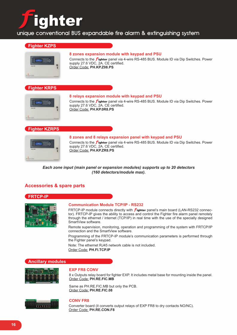
Fighter KZPS
8 zones expansion module with keypad and PSU Connects to the panel via 4-wire RS-485 BUS. Module ID via Dip Switches. Power supply 27.6 VDC, 2A. CE certified.Order Code: PH.KP.Z08.PS
Fighter KRPS
8 relays expansion module with keypad and PSUConnects to the panel via 4-wire RS-485 BUS. Module ID via Dip Switches. Power supply 27.6 VDC, 2A. CE certified.Order Code: PH.KP.0R8.PS
Fighter KZRPS
8 zones and 8 relays expansion panel with keypad and PSUConnects to the panel via 4-wire RS-485 BUS. Module ID via Dip Switches. Power supply 27.6 VDC, 2A. CE certified.Order Code: PH.KP.ZR8.PS
Each zone input (main panel or expansion modules) supports up to 20 detectors(160 detectors/module max).
Accessories & spare parts
FRTCP-IP
Communication Module TCP/IP - RS232FRTCP-IP module connects directly with panel’s main board (LAN-RS232 connec-tor). FRTCP-IP gives the ability to access and control the Fighter fire alarm panel remotely through the ethernet / internet (TCP/IP) in real time with the use of the specially designed SmartView software. Remote supervision, monitoring, operation and programming of the system with FRTCP/IP connection and the SmartView software.Programming of the FRTCP-IP module’s communication parameters is performed through the Fighter panel’s keypad.Note: The ethernet RJ45 network cable is not included.Order Code: PH.FI.TCP.IP
Ancillary modules
EXP FR8 CONV 8 x Outputs relay board for fighter EXP. It includes metal base for mounting inside the panel.Order Code: PH.RE.FIC.MB
Same as PH.RE.FIC.MB but only the PCB. Order Code: PH.RE.FIC.08
CONV FR8 Converter board (it converts output relays of EXP FR8 to dry contacts NO/NC).Order Code: PH.RE.CON.F8

17
unique conventional BUS expandable fire alarm & extinguishing system
Spare parts
FIGHTER Keypad Fighter panel’s keypad.Order Code: PH.KP.FIL.GR
FIGHTER Main Board Fighter panel’s main board.Order Code: PH.MN.FIT.08
EXP Z8 PCB expansion module with 8 zone inputs. All inputs are fully supervised and must be properly terminated. Capability for extra Power Supply (FPS-5, transformer and batteries) with fully supervised mains and battery inputs. Each zone input (main panel or expansion modules) supports up to 20 detectors (160 detectors max). Connection via BUS. Module ID via Dip Switches.Order Code: PH.ZE.FIT.08
EXP R8 PCB expansion module with 8 relays. All outputs are supervised and must be properly terminated. 24VDC/1A output per relay (fused). Maximum load depends on rest of system. Capability for extra Power Supply (FPS-5, transformer and batteries) with fully supervised mains and battery inputs. Provides the ability to connect a wide variety of loads (notification appliances, automation modules etc). Connection via BUS. Module ID via Dip Switches.Order Code: PH.RE.FIT.08
FPS-5 Switching stabilized power supply 27,6 VDC - 2A without transformer (PCB board only). When connected to the main board it provides mains supervision, battery charger, battery health monitor (high internal impedance detection) and short circuit protection for the battery charger. CE certified.Order Code: PH.PF.005.V1
SmartView Software
Unified platform for programming and remote monitoring of Fire Alarm panelsSmartView is a unique software application designed to connect to ALL our panels. This way the learning curve for the installing engineers is minimized to the use of a single app. The software supports different languages and it can integrate new ones with the use of a single translation file (provided from our company).SmarView keeps constantly checking the communication health between itself and any con-nected panel, informing the owner or installer in case of any discrepancy or problem.SmartView provides both the installing engineer and the end user/owner of a Fire Alarm sys-tem a powerful tool that provides:
■ Connectivity over any TCP/IP network over either a LAN or a remote connection to any PH Svesis’ panel including Matrix2000, Fighter and SmartX product lines
■ Full remote monitoring of panels e.g. alarm, fault, bypass etc ■ Access to remote programming for the installing engineer e.g. zone names and descriptions,
cross zoning delays, activation grouping etc ■ Access to remote operations for the user e.g. silence, reset and/or evacuation ■ Graphical loop overview of connected devices (SmartX analogue addressable panels only) ■ Interactive Floor Plans giving detailed and accurate information of what’s happening in the
protected area ■ Integration of LIVE Video feed from within the GUI ■ 20 simultaneous and independent LIVE fully operating connections to as many panels in
different windows from one PC/workstation

18
General Specifications ■ Advanced conventional fire alarm & extinguishing panel using Bus technology. ■ 1 Extinguishing area with 8 zones ■ Up to a maximum of 8 keypads units. ■ LCD keypad unit for supervision, monitoring, operation and programming of the system. ■ Build-in DTMF communicator supports Ademco C.I.D. format. ■ Serial (RS232) connection for supervision, monitoring, operation and programming of the system through the
SmartView software and the RS-232/485 module (optional). ■ Remote supervision, monitoring, operation and programming of the system with TCP/IP connection and the
SmartView software (optional). ■ Intellizone and Cross-zone feature. ■ Walk Test feature. ■ Day / Night feature. ■ Certified to European directives ΕΝ 54-2:1997/Α1:2006/AC:1999, ΕΝ 54-4:1997/Α2:2006/AC:1999 & ΕΝ12094-
1:2003 (Extinguishing).
Technical SpecificationsBus voltage 24VDC typicalCurrent at 24Vdc per PSU 1.8 AMain board current draw [Standby / Alarm] 112 mA / 350 mAZones Expansion Module current draw [Standby / Alarm] 60mA / 220 mARelays Expansion Module current draw [Standby / Alarm] 40mA / 230 mAKeypads current draw [Standby / Alarm] 25 mA / 110 mAAuxiliary output 24VDC +/- 10%, 800 mA max, current limited, monitoredBatteries 2x 12V, 7Ah sealed lead acid gel, self regulatedZone Inputs Voltage 16.3 VDC ±10%, 0,5 V max ripple voltageZone Reset Operation 0,5 VDC max voltage, duration 3,1 secMax total detector’s standby current per zone 15 mASignalling devices outputs 24VDC ±10%, 1A max, fused and monitoredFault relay contacts rating Dry contacts (NO/NC) 30 VDC, 3 AmpsBUS system 4 wire RS485 bus systemBus max length 1200m using typical RS485 cablesBus Max capacitive load 400 nFDimensions (HxWxD [mm]) 315x425x100
EC Certificate Number1293-CPR-0525
unique conventional extinguishing system

19
Fighter XT FRTCP-IP RS-232PSTN
TCP-IP
8 zones panel with8 relay outputs
TCP-IP/RS-232 module
Central MonitoringStation
LAN/WAN
Phone LineProvider
Fighter ProVision
SmartView
Active
ActiveActive
Active
Active
Active
Detection Zone 1
Detection Zone 2
Z1Z2
First Level Alarm Second Level Alarm Extinguishing Active
Siren
Extinguish Command
Pre-Release
Pressure Damper
RL1RL2RL3RL4
First Alarm
Gas Released
Pressure Damper, INV
Verified Outflow
RL5RL6RL7RL8
Mode 1 & Mode 2 Outputs
Mode 2 Only Outputs
Activated
Active ← T1 →T2 →T4 →← T3
T4 →← T3
Activated
Continuous SoundInterrupted SoundInterrupted Sound
Time Line →
(0= Inactive)
Extinguishing panel operational overview
Detection 1(1st zone)
Detection 2(2nd zone)
HOLD(3rd zone)
Extinguish(4th zone)
ExtinguishAuxiliary(7th zone)
(5th zone) (6th zone)Manual Mode
Switch(8th zone)
PressureControlSensor
ReleaseControlSensor
unique conventional extinguishing system

20
Fighter XT
8 zones and 8 relays conventional fire alarm & extinguishing panel1 Extinguishing area with 8 zones. Up to a maximum of 8 keypads units per system. Built in communicator supporting Contact I.D protocol. Power supply 27.6 VDC, 2A. CE certified.Order Code: PH.PL.FXT.R8
Fighter KSDA
LCD remote Keypad/Repeater ■ User friendly Alphanumeric keypad - repeater with 80 characters (4 x 20) blue LCD
display. ■ Menu-driven programming for easy system setup (installer). ■ Menu-driven user friendly operation. ■ 3 LEDs indicate the status of the power supply, alarms and faults of the system. ■ Backlit button gives access and indicates access levels 2 and 3. ■ TEST button activates all visual indicators for user check. ■ Dedicated system (zones) reset button. ■ Dedicated Silence button for buzzers and external sirens also indicates active silence
conditions. ■ Easy user information and system status with clever filtering through 4 buttons. Filtering
alarms, faults, bypasses and log events creates easy to comprehend uncluttered display screens.
■ 12 alphanumeric buttons for data input during system programming (e.g. zone’s descriptions).
■ Easy menu navigation with dedicated arrow buttons. ■ Info button gives on screen quick help for system parameters and screen items. ■ Evacuation Command with keys combination (1 + 3 key buttons) ■ Interconnection via RS-485 BUS system. ■ Dimensions (HxWxD [mm]): 110 x 155 x 25.
Order Code: PH.KP.FIS.EN
Sequential Extinguishing Activator
Device used to relay the Extinguishing command from the panel’s output to more than one extinguishing generators. It reduces the current needed from the panel to activate these multiple generators by triggering them in sequence with a programmable delay from one activation to the next one. Open and short circuit on every part of the chain is detected and reported to the panel.Order Code: PH.SE.ACT.RD
Manual Mode Switch
2-position keyswitch in a metal enclosure. When Auto is enabled the panel operates in the normal way. When Manual is enabled the panel does not initiate any Extinguishing procedure unless the START extinguishing button is pressed. The panel indicates “Manual mode” in the main LCD display.Order Code: PH.FI.MMS.00
unique conventional extinguishing system

21
unique conventional extinguishing system
FRTCP-IP
Communication Module TCP/IP - RS232FRTCP-IP module connects directly with panel’s main board (LAN-RS232 connec-tor). FRTCP-IP gives the ability to access and control the Fighter fire alarm panel remotely through the ethernet / internet (TCP/IP) in real time with the use of the specially designed SmartView software. Remote supervision, monitoring, operation and programming of the system with FRTCP/IP connection and the SmartView software.Programming of the FRTCP-IP module’s communication parameters is performed through the Fighter panel’s keypad.Note: The ethernet RJ45 network cable is not included.Order Code: PH.FI.TCP.IP
Ancillary modules
EXP FR8 CONV 8 x Outputs relay board for Fighter XT. It includes metal base for mounting inside the panel.Order Code: PH.PL.FIP.R8
Same as PH.RE.FIC.MB but only the PCB. Order Code: PH.RE.FIC.08
CONV FR8 Converter board (it converts output relays of EXP FR8 to dry contacts NO/NC).Order Code: PH.RE.CON.F8
SmartView Software
Unified platform for programming and remote monitoring of Fire Alarm panelsSmartView is a unique software application designed to connect to ALL our panels. This way the learning curve for the installing engineers is minimized to the use of a single app. The software supports different languages and it can integrate new ones with the use of a single translation file (provided from our company).SmarView keeps constantly checking the communication health between itself and any con-nected panel, informing the owner or installer in case of any discrepancy or problem.SmartView provides both the installing engineer and the end user/owner of a Fire Alarm sys-tem a powerful tool that provides:
■ Connectivity over any TCP/IP network over either a LAN or a remote connection to any PH Svesis’ panel including Matrix2000, Fighter and SmartX product lines
■ Full remote monitoring of panels e.g. alarm, fault, bypass etc ■ Access to remote programming for the installing engineer e.g. zone names and descriptions,
cross zoning delays, activation grouping etc ■ Access to remote operations for the user e.g. silence, reset and/or evacuation ■ Graphical loop overview of connected devices (SmartX analogue addressable panels only) ■ Interactive Floor Plans giving detailed and accurate information of what’s happening in the
protected area ■ Integration of LIVE Video feed from within the GUI ■ 20 simultaneous and independent LIVE fully operating connections to as many panels in
different windows from one PC/workstation

22
conventional fire alarm panel
General Specifications ■ Conventional Fire alarm panel. ■ 2, 4 or 8 conventional zones. ■ Active End of Line monitored zones. ■ 4 fully monitored Siren/Relay outputs. ■ Constant or ANSI sound output patterns. ■ Universal Access Level 2 key (key code access as well). ■ Alarm verification with pre-alarm output. Configurable for each zone. 7 delay values. ■ Day/Night operation (with external timer). ■ Output delays (7 values). ■ Cross zone (dual zone) alarms. Configurable on each zone pair (4 pairs on 8 zone model). ■ 24VDC Auxiliary output. ■ 24VDC output, interruptible during reset (eg for gas detector reset). ■ Remote reset input. ■ Bell (clash change) input. ■ Walk test (individual zone capable). ■ Repeater expansion port. ■ TCP/IP module expansion port. ■ High quality and reliability relays used throughout the design. ■ Alarm and Fault/Disablement indicators for each zone. ■ Certified to directive CPR 89/106/EEC, EN 54-2: 1997/A1: 2006/AC: 1999 and EN 54-4: 1997/A2: 2006/AC:
1999. Certified to LVD Directive 2006/95/EC and EMC Directive 2004/108/EC.
Technical SpecificationsMains power 230 VAC/50HzMax power 100 VA max input powerStandby power 5 VAAuxiliary power output 24VDC 1.5 AmpZone termination 22uF / 25V capacitorsMonitored output termination 4.7 Kohms resistorsFire relay output Dry contacts NO or NC selectableOperating Humidity 5% to 95% RH, noncondensingOperating Temperature -2oC to 45oC (32oF to 120oF)Panel’s dimensions (HxWxD) [mm] 315 x 425 x 105Semi flush wall mounting 25 mm max height
CPD Certificate Number1293-CPR-004
EC Certificate Number0040/101/1/2018

23
General Specifications ■ Fire alarm control panel for small or medium installations. ■ Number of zones: 4, 8, 12, 16, 20 or 24. Maximum number of detectors per zone 20. ■ Two wire zone circuits (Class B, Style C). ■ Outputs expandability up to 24 relays zone outputs. ■ Zones Bypass (zone disablements) keys. ■ Silicon rubber keypad for Operation and Programming. ■ Keyswitch to access Level 2 and Evacuation procedure. ■ Zone status indication: Alarm, Fault, Bypassed. ■ General LED indications: Power, Alarm, Fault, Silence, AUX Fault, Siren Fault, Relays Outputs Fault. ■ Earth Fault indication. ■ IntelliZone (Alarm Verification) feature. Similar to Day/Night mode. ■ Cross-zone feature (up to 4 cross-zone pairs). Only for the mainboard’s zones. ■ WalkTest installation testing feature. ■ Weekly reminder for system test. ■ Remote connectivity through serial and ethernet expansion boards (optional extras). ■ Supervision, monitoring and operation through the ViewMatrixPlus software. ■ Certified to directive CDP 89/106/EEC, EN 54-2: 1997/A1: 2006/AC: 1999 and EN 54-4: 1997/A2: 2006/AC:
1999. Certified to LVD Directive 2006/95/EC and EMC Directive 2004/108/EC.
Technical SpecificationsMains power 220V AC 50Hz or 110V AC 60HzAccessories operational voltage 24V DCBackup power 2x 12V / 7Ah sealed lead acid gel batteriesBattery health monitoring (periodic load test) Every 90 secondsEarth faults detection and indication Front panel LED & buzzerZone termination resistors 4,7Κ Ohms / 0.5WRelay outputs termination resistors 4,7Κ Ohms / 0.5WSupervised siren output 24VDC / 1A outputSupervised, fused relay outputs on the relay expansion modules 1.5A fuse
Panel’s current consumption at 24VDC (standby)4 zones: 55mA, 8 zones: 70mA, 12 zones: 95mA, 16 zones: 110mA, 20 zones: 135mA, 24 zones: 150mA
Panel’s dimensions (HxWxD) [mm]4 - 8 zones: 315 x 425 x 9012 - 16 zones: 480 x 425 x 9020 - 24 zones: 645 x 425 x 90
Generic trouble output (on main unit) non monitored Dry relay contacts NO - C - NC.Operating Temperature -2oC to 45oC (32oF to 120oF)Operating Humidity 5% to 95% RH, noncondensing
CPD Certificate Number1293-CPD-0185
EC Certificate Number00223/101/1/2010
conventional fire alarm panels

24
RS-4
85
TCP-IP TCP-IP
Matrix2008
8 zones Fire Alarm Panel
LAN/WAN
SmartView
Matrix2024
24 zones Fire Alarm Panel
Matrix RPT 8Z
8 zones Repeater
Matrix RPT 24Z
24 zones Repeater
MRTCP-IP
Ethernet & RS-485module
MRTCP-IP
Ethernet & RS-485module
RS-4
85
conventional fire alarm panels
25
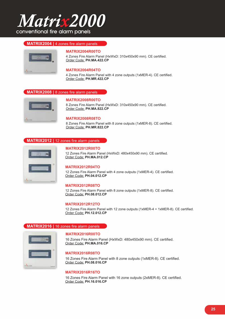
MATRIX2004 | 4 zones fire alarm panels
MATRIX2004R00TO 4 Ζones Fire Alarm Panel (HxWxD: 310x450x90 mm). CE certified.Order Code: PH.MA.422.CP
MATRIX2004R04TO 4 Ζones Fire Alarm Panel with 4 zone outputs (1xMER-4). CE certified.Order Code: PH.MR.422.CP
MATRIX2008 | 8 zones fire alarm panels
MATRIX2008R00TO 8 Ζones Fire Alarm Panel (HxWxD: 310x450x90 mm). CE certified.Order Code: PH.MA.822.CP
MATRIX2008R08TO 8 Ζones Fire Alarm Panel with 8 zone outputs (1xMER-8). CE certified.Order Code: PH.MR.822.CP
MATRIX2012 | 12 zones fire alarm panels
MATRIX2012R00TO 12 Ζones Fire Alarm Panel (HxWxD: 480x450x90 mm). CE certified.Order Code: PH.MA.012.CP
MATRIX2012R04TO 12 Ζones Fire Alarm Panel with 4 zone outputs (1xMER-4). CE certified.Order Code: PH.04.012.CP
MATRIX2012R08TO 12 Ζones Fire Alarm Panel with 8 zone outputs (1xMER-8). CE certified.Order Code: PH.08.012.CP
MATRIX2012R12TO 12 Ζones Fire Alarm Panel with 12 zone outputs (1xMER-4 + 1xMER-8). CE certified.Order Code: PH.12.012.CP
MATRIX2016 | 16 zones fire alarm panels
MATRIX2016R00TO 16 Ζones Fire Alarm Panel (HxWxD: 480x450x90 mm). CE certified.Order Code: PH.MA.016.CP
MATRIX2016R08TO 16 Ζones Fire Alarm Panel with 8 zone outputs (1xMER-8). CE certified.Order Code: PH.08.016.CP
MATRIX2016R16TO 16 Ζones Fire Alarm Panel with 16 zone outputs (2xMER-8). CE certified.Order Code: PH.16.016.CP
conventional fire alarm panels

26
MATRIX2020 | 20 zones fire alarm panels
MATRIX2020R00TO 20 Ζones Fire Alarm Panel (HxWxD: 650x450x90 mm). CE certified.Order Code: PH.MA.020.CP
MATRIX2020R04TO 20 Ζones Fire Alarm Panel with 4 zone outputs (1xMER-4). CE certified.Order Code: PH.04.020.CP
MATRIX2020R08TO 20 Ζones Fire Alarm Panel with 8 zone outputs (1xMER-8). CE certified.Order Code: PH.08.020.CP
MATRIX2020R12TO 20 Ζones Fire Alarm Panel with 12 zone outputs (1xMER-4 + 1xMER-8). CE certified.Order Code: PH.12.020.CP
MATRIX2020R16TO 20 Ζones Fire Alarm Panel with 16 zone outputs (2xMER-8). CE certified.Order Code: PH.16.020.CP
MATRIX2020R20TO 20 Ζones Fire Alarm Panel with 20 zone outputs (1xMER-4 + 2xMER-8). CE certified.Order Code: PH.12.020.CP
MATRIX2024 | 24 zones fire alarm panels
MATRIX2024R00TO 24 Ζones Fire Alarm Panel (HxWxD: 645x425x100 mm). CE certified.Order Code: PH.MA.024.CP
MATRIX2024R08TO 24 Ζones Fire Alarm Panel with 8 zone outputs (1xMER-8). CE certified.Order Code: PH.08.024.CP
MATRIX2024R16TO 24 Ζones Fire Alarm Panel with 16 zone outputs (2xMER-8). CE certified.Order Code: PH.16.024.CP
MATRIX2024R24TO 24 Ζones Fire Alarm Panel with 24 zone outputs (3xMER-8). CE certified.Order Code: PH.24.024.CP
conventional fire alarm panels

27
RepeatersMatrix2000 repeaters provide a remote indication and operation of the fire panel. The user interface has the same controls and indications as the main panel. It is connected to the main panel with a 4 wire cable (RS485 and power). Attention: In order to connect the repeaters to a panel, module MRS232/485 is required. Cables are not included.
MATRIX RPT 4Z 4 zones repeater Dimensions: 320x170x50mm (Requires MRS23/485 communication module).Order Code: PH.RP.004.NW
MATRIX RPT 8Z 8 zones repeater Dimensions: 320x170x50mm (Requires MRS23/485 communication module).Order Code: PH.RP.008.NW
MATRIX RPT 12Z 12 zones repeater Dimensions: 320x290x50mm (Requires MRS23/485 communication module).Order Code: PH.RP.012.NW
MATRIX RPT 16Z 16 zones repeater Dimensions: 320x290x50mm (Requires MRS23/485 communication module).Order Code: PH.RP.016.NW
MATRIX RPT 20Z 20 zones repeater Dimensions: 320x405x50mm (Requires MRS23/485 communication module).Order Code: PH.RP.020.NW
conventional fire alarm panels
28
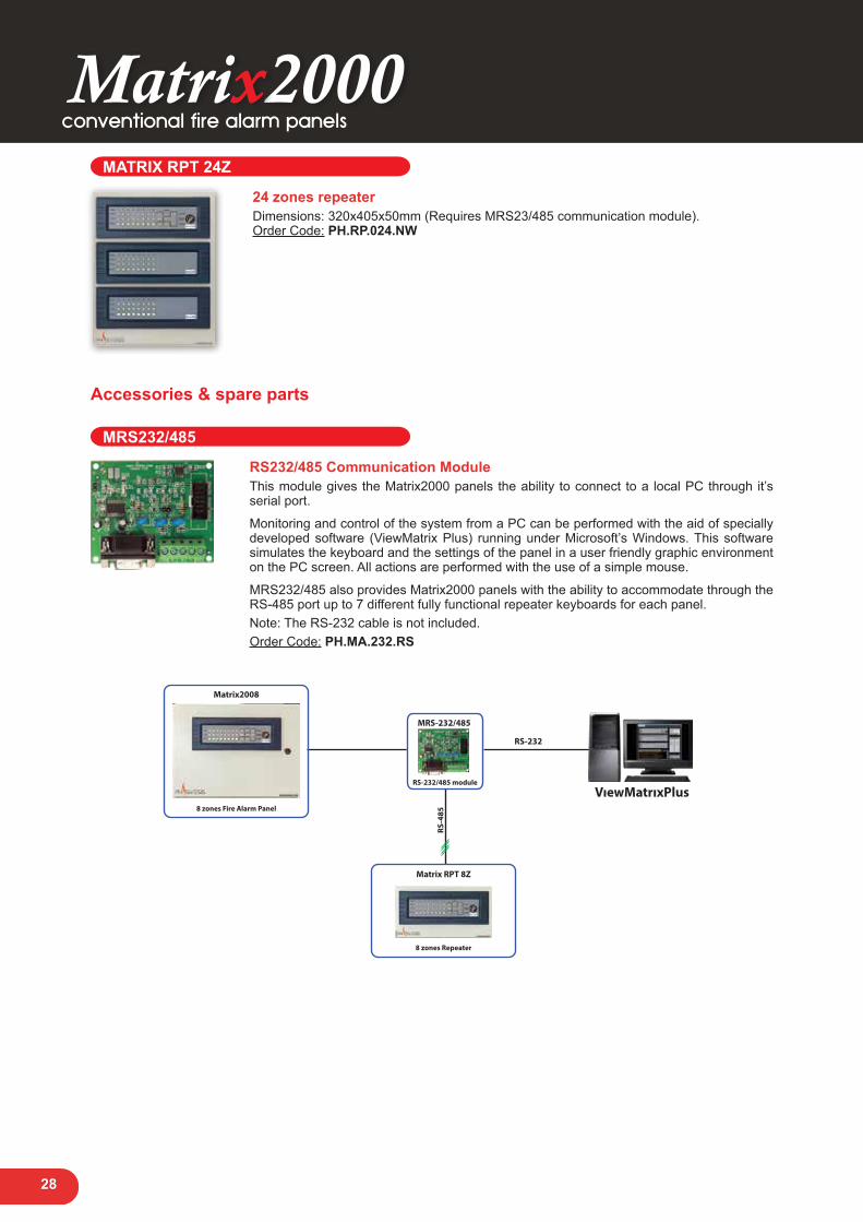
MATRIX RPT 24Z 24 zones repeater Dimensions: 320x405x50mm (Requires MRS23/485 communication module).Order Code: PH.RP.024.NW
Accessories & spare parts
MRS232/485
RS232/485 Communication Module This module gives the Matrix2000 panels the ability to connect to a local PC through it’s serial port.
Monitoring and control of the system from a PC can be performed with the aid of specially developed software (ViewMatrix Plus) running under Microsoft’s Windows. This software simulates the keyboard and the settings of the panel in a user friendly graphic environment on the PC screen. All actions are performed with the use of a simple mouse.
MRS232/485 also provides Matrix2000 panels with the ability to accommodate through the RS-485 port up to 7 different fully functional repeater keyboards for each panel.Note: The RS-232 cable is not included.Order Code: PH.MA.232.RS
RS-232
RS-4
85
VıewMatrıxPlus
Matrix RPT 8Z
8 zones Repeater
MRS-232/485
RS-232/485 module
Matrix2008
8 zones Fire Alarm Panel
conventional fire alarm panels

29
MRTCP/IP
Ethernet & RS485 Communication Module The MRTCP/IP module connects directly to the main board of the Matrix 2000 panel. Pro-vides full access and control of the panel either locally via RS485 serial connection to repeaters or via internet (TCP/IP) to any PC running the specially designed software View-Matrix Plus in real time.
Connecting the MRTCP/IP module reduces the maximum number of repeaters that can be connected to the panel Matrix2000 from 7 to 6.
The programming of communication parameters of the module is done through a specially designed software named “Matrix Network Utility” which can be found on our website www.paradox.gr.Note: The ethernet RJ45 network cable is not included. Order Code: PH.RB.TCP.IP
Ancillary module
Dual Siren output Module Extension board for Matrix2000 panels. Provides 2 x Siren outputs and 1 x General Alarm Dry Contact Output NO/NC (Applicable to 8, 16 and 24 zone panels using MAIN-8 board).Order Code: PH.SR.EXP.8Z
Extension board for Matrix2000 panels. Provides 2 x Siren outputs and 1 x General Alarm Dry Contact Output NO/NC (Applicable to 4, 12 and 20 zone panels using MAIN-4 board).Order Code: PH.SR.EXP.4Z
Spare parts
MAIN-4 4 zones main board for MATRIX2004, MATRIX2012 & MATRIX2020 panel series.Order Code: PH.MN.004.V3
MAIN-8 8 zones main board for MATRIX2008, MATRIX2016 & MATRIX2024 panel series.Order Code: PH.MN.008.V3
MEZ-8 8 zones expansion board.Order Code: PH.MZ.008.00
MER-4 4 zone outputs expansion board.Order Code: PH.MR.104.V2
MER-8 8 zone outputs expansion board.Order Code: PH.MR.108.V2
conventional fire alarm panels

30
MKP-4 4 zones keypad with keyswitch.Order Code: PH.MK.004.V2
MKP-8K8 zones keypad with keyswitch.Order Code: PH.MK.008.V2
MKP-8 8 zones expansion keypad without keyswitch (Need to order zone numbers 9-16 and 17-24).Order Code: PH.MK.108.V2
FPS-4 Switching stabilized power supply 27,6 VDC - 2A without transformer (PCB board only). When connected to the Matrix2000 main board provides mains supervision, battery char-ger, battery health monitor (high internal impedance detection) and short circuit protection for the battery charger.Order Code: PH.PF.004.V1
SmartView Software Unified platform for programming and remote monitoring of Fire Alarm panelsSmartView is a unique software application designed to connect to ALL our panels. This way the learning curve for the installing engineers is minimized to the use of a single app. The software supports different languages and it can integrate new ones with the use of a single translation file (provided from our company).SmarView keeps constantly checking the communication health between itself and any con-nected panel, informing the owner or installer in case of any discrepancy or problem.SmartView provides both the installing engineer and the end user/owner of a Fire Alarm sys-tem a powerful tool that provides:
■ Connectivity over any TCP/IP network over either a LAN or a remote connection to any PH Svesis’ panel including Matrix2000, Fighter and SmartX product lines
■ Full remote monitoring of panels e.g. alarm, fault, bypass etc ■ Access to remote programming for the installing engineer e.g. zone names and descriptions,
cross zoning delays, activation grouping etc ■ Access to remote operations for the user e.g. silence, reset and/or evacuation ■ Graphical loop overview of connected devices (SmartX analogue addressable panels only) ■ Interactive Floor Plans giving detailed and accurate information of what’s happening in the
protected area ■ Integration of LIVE Video feed from within the GUI ■ 20 simultaneous and independent LIVE fully operating connections to as many panels in
different windows from one PC/workstation
conventional fire alarm panels

31
conventional peripherals
Conventional Peripherals
Detectors
NB323-2 2 wire Rate of Rise/Fixed temperature Heat Detector. Base included.Order Code: PH.SD.323.20
NB338-2 2 wire photoelectric smoke alarm detector. Base included.Order Code: PH.HD.338.20
Ancillary modules
MRB-01 Fire beams resetting board.Order Code: PH.AU.RES.MF
MED-01 Extinguishing delay board.Order Code: PH.EX.DEL.MO
Indoor sirens
PH-84 Indoor siren with flash / 120dB.Order Code: PH.LD.084.FS
PH-81Indoor siren with flash / 88dB.Order Code: PH.LD.081.FS
32
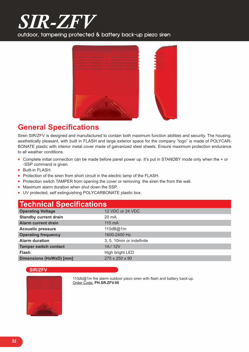
SIR-ZFV
General SpecificationsSiren SIR/ZFV is designed and manufactured to contain both maximum function abilities and security. The housing, aesthetically pleasant, with built in FLASH and large exterior space for the company “logo” is made of POLYCAR-BONATE plastic with interior metal cover made of galvanized steel sheets. Ensure maximum protection endurance to all weather conditions.
■ Complete initial connection can be made before panel power up. It’s put in STANDBY mode only when the + or -SSP command is given.
■ Built-in FLASH. ■ Protection of the siren from short circuit in the electric lamp of the FLASH. ■ Protection switch TAMPER from opening the cover or removing the siren the from the wall. ■ Maximum alarm duration when shut down the SSP. ■ UV protected, self extinguishing POLYCARBONATE plastic box.
Technical SpecificationsOperating Voltage 12 VDC or 24 VDCStandby current drain 20 mAAlarm current drain 115 mAAcoustic pressure 110dB@1mOperating frequency 1600-2400 HzAlarm duration 3, 5, 10min or indefiniteTamper switch contact 1A / 12VFlash High bright LEDDimensions (HxWxD) [mm] 275 x 250 x 90
outdoor, tampering protected & battery back-up piezo siren
SIR/ZFV 110db@1m fire alarm outdoor piezo siren with flash and battery back-up.Order Code: PH.SR.ZFV.00
Security Systems

34
General SpecificationsThe SIR/PL and SIR/V siren series are designed and manufactured to contain both maximum function abilities and security.The housing aesthetically pleasant, with built in FLASH and large exterior room for the company “logo” is made of POLYCARBONATE plastic. Interior metal cover made of galvanized steel sheets. The robust design and excellent material ensure maximum protection endurance to all weather conditions.SIR/PLL & SIR/V are certified to EN50131-4 Standard, Security Grade 3, Environmental Class IV.
■ Complete initial connection can be made before panel power up. It’s put in STANDBY mode only when the + or -SSP command is given.
■ The siren is activated when the alarm panel’s voltage drops below 9.5 VDC. ■ High Bright LED Flash. ■ Protection of the siren from short circuit in the Flash. ■ Protection switch TAMPER from opening the cover or removing the siren from the wall. ■ Maximum alarm duration when the SSP is off. ■ UV protected, self extinguishing Polycarbonate plastic box. ■ Available in white and silver color.
Technical SpecificationsOperating Voltage 11-14 VDCStandby current drain 12mA ±5%Alarm current drain 1.6A ±5%Supported Battery Type 12V 2.3Ah / 12V 7Ah (SIR/PL), 12V 2.3Ah (SIR/V)Acoustic Pressure 110dB ±5%@1mType of acoustic output Acoustic output is modulated toneOperating Frequency (Audio) 1600 - 2400 Hz
Alarm Duration (Factory setting)1. From 4 to 5 min2. From 5 to 6 min3. From 8 to 10 min
Dimensions (HxWxD) [mm] 275 x 250 x 90Max. Tamper Switch Ratings 1A / 30VVisual Alarm Indicator High Bright LEDSSP Voltage ± 12VDimensions (HxWxD) [mm] 275x250x90
Weight 2.7Kgr. (SIR/PLL), 2.4Kgr. (SIR/PLSL), 2.52Kgr. (SIR/V),2.07Kgr. (SIR/VS)
SIR/PL - Voutdoor, tampering protected & battery back-up siren series
EC Certificate NumberSIR/V: 00052/101/1/2016
SIR/PLL: 00051/101/1/2016Certified EN50131-4
Security Grade 3, Environmental Class IV

35
SIR/PL - Voutdoor, tampering protected & & battery back-up siren series
SIR/PL SIR/PLL Outdoor siren with flash and battery back-up. Can fit 7 or 2,3Ah battery. Available in white & silver color. FLASH in white, orange or blue color. EN50131-4 certified. Security Grade 3, Environmental Class IV.Order Code: PH.SR.PLL.00
SIR/PLSL Outdoor siren with flash and battery back-up. Can fit 7 or 2,3Ah battery. Available in white & silver color. FLASH in white, orange or blue color. Order Code: PH.SR.PLS.00
SIR/V
SIR/V Outdoor siren with flash and battery back-up. Can fit 2,3Ah battery. Available in white & silver color. FLASH in red color. EN50131-4 certified. Security Grade 3, Environmental Class IV.Order Code: PH.SR.PLV.0W
SIR/VS Outdoor siren with flash and battery back-up. Can fit 2,3Ah battery. Available in white & silver color. FLASH in red color. CE certified.Order Code: PH.SR.PSV.0W

36
General SpecificationsSIRION IP Communication Module provides:
■ Support of burglar alarm panels in installations with VoIP fixed telephony services. ■ Ability of constant communication between the panel and the Central Monitoring Station (DSL connection
required) with no extra charges for the end user (PSTN networks charges are dependent on the call time). ■ Provides an upgrade path of existing older systems to modern communication methods (with no need for
replacing existing equipment).SIRION connects easily to the alarm panel (on TIP / RING output). Plug & Play; all basic programming is included in HTML pages inside SIRION. Easily connects to other backup systems (e.g. artion GSM unit). Compatible with ALL burglar alarm panels regardless of manufacturer or model.
Also includes: ■ 4 different operational modes. ■ Activate / Deactivate 2 onboard PGMs through web browser (e.g. Internet Explorer). ■ LED indicators for the state of PGMs, power and heartbeat (good working status) of the module. ■ Very low network bandwidth consumption. ■ Use of encryption (AES-128) for secure data communication.
Technical SpecificationsOperating Voltage 12 VDCCurrent consumption 200mA max2 PGM (open collector, active low)Conventional telephony line (POTS) output to alarm panelPSTN input8 LED indicators for SIRION’s status and conditionRJ45 Ethernet connectorSerial connection for programming and expansion featuresDetachable connector block for easy installation
SirionIP communication module

37
Sirion
PSTN Network
INTERNET
Monitoring Station router with UPS
SIRION Server
PSTN (signal) Receıver
Monitoring Station’s Server
Sirion
IP Communication Module Home router with UPS
Alarm Panel
Installation
Central Monitoring Station
IP communication module

38
Sirion IP communication module Universal module for IP communication and event reporting to a central monitoring station compatible with all burglar alarm panels using Contact ID format.Order Code: PH.IP.SIR.02
PSTN Isolator PSTN isolator module It releases the telephone line, isolating the phones to communicate with the central station.Order Code: PH.IP.SIR.03
Sirion Server SoftwareSirion Server Software Sirion server is a dedicated software that bridges TCP/IP communications from sirion with monitoring station’s receiving equipment. It receives event data originating either form the alarm panel and/or the sirion unit(s), decodes them and translates them to the format ex-pected by the rest of the monitoring system by emulating a range of popular PSTN event receivers. It also serves as a sirion units presence and connectivity watchdog, reducing from existing software from the overhead of continues and frequent monitoring.
■ Server software for reception of alarm and periodic tests events. ■ Compatible with existing software by simulating widely spread protocols (MCDI
Exprecium, Ademco 685, Surgard SLR, Raw data. ■ Connectivity with monitoring system through physical serial port, emulated serial port,
TCP/IP or file system sharing ■ High security encryption and authentication protocol ■ Unit presence and connectivity watchdog with programmable per unit parameters ■ Fully logged operation (incoming, system and user events)
SirionIP communication module

Emergency Luminaires

40
Self-testing smart luminaires
General Specifications ■ Indoor EXIT sign for ceiling or wall mounting. ■ Control and programming button. ■ 3 x status LEDs and reset button. ■ Built-in self-test feature. ■ Easy identification of Faults (battery, lighting
elements). ■ Slim design. ■ Fast and easy installation. ■ Five (5) luminance levels for each operating mode. ■ This EXIT sign comes in 2 variations for areas up to 20 meters (exidus 1) of visibility or up to 30 meters (exidus
2) of visibility. ■ ENEC approved. Certified to EN60598. ■ The EXIDUS emergency lighting can be provided with left, right or down pointing arrows.
Technical SpecificationsPower Supply 230VAC / 50HzMax. Power Consumption Less than 5VALight Source 12 LEDBattery 3.6V 1.0Ah NiCdEmergency Operation Time From 150min to 240min depending on luminance settingLuminance setting 5 steps (20, 40, 60, 80 & 100%)Light source intensity (230V) 100lmMounting Wall / ceilingSwitch over Voltage Between 150 ~ 190VIP rating IP20Isolation Category Double isolationEnvironmental Temperature: +5 to 45 °C, Humidity: 5 to 95% RH, non condensatingIndication Area Dimensions [WxHxD] 314x150x6 mm (exidus1), 314x100x6 mm (exidus2)Dimensions [WxHxD] Main body: 320x64x27mmGuarantee 3 years (1 year for the battery)
Exidus 1 Exidus 1 Up to 20m viewing distance.Order Code: Left arrow: PH.LE.EXD.10 Right arrow: PH.RI.EXD.10 Down arrow: PH.DN.EXD.10
Exidus 2 Up to 30m viewing distance.Order Code: Left arrow: PH.LE.EXD.14 Right arrow: PH.RI.EXD.14 Down arrow: PH.DN.EXD.14
Angular Light Distribution

41
Self-testing smart luminaire
General Specifications ■ Indoor luminaire for wall mounting. ■ Control and programming button. ■ 3 x status LEDs and reset button. ■ Built-in self-test feature. ■ Can be used for Emergency lighting (non-
maintained) and also for Ambient lighting (maintained).
■ Easy identification of Faults (battery, lighting elements).
■ Slim design (only 27mm depth). ■ Easy installation and easy battery replacement. ■ Five (5) luminance levels for each operating mode. ■ ENEC approved. Certified to EN60598. ■ Left, right and down pointing arrow stickers are included.
Technical SpecificationsPower Supply 230VAC/50HzMax. Power Consumption Less than 5VALight Source 12 LEDBattery 3.6V 1.0Ah NiCdEmergency Operation Time From 150 min to 240 min depending on luminance settingLuminance setting 5 steps (20, 40, 60, 80 & 100%)Light source intensity (230V) 100lmMounting WallSwitch over Voltage Between 150 ~ 190VIP rating IP20Isolation Category Double isolation
Environmental Temperature: +5 to 45 °C Humidity: 5 to 95% RH, non condensating
Indication Area Dimensions [WxHxD] 228x75 mmDimensions [WxHxD] 260x125x33.5 mmGuarantee 3 years (1 year for the battery)
Elix
Self-testing smart luminaire Elix in white color.Order Code: PH.EL.ELX.WT
Angular Light Distribution

42
Self-testing smart luminaire
General Specifications ■ Indoor luminaire for wall or ceiling mounting. ■ Fancy design that blends in effortlessly with modern spaces. ■ Unique design with 3 distinct light elements arranged in an arc. ■ Built-in self-test feature. ■ Can be used for Emergency lighting (non-maintained) and also for Ambient lighting (maintained). ■ Easy identification of Faults (battery, lighting elements). ■ Easy installation and easy battery replacement. ■ Five (5) luminance levels for each operating mode. ■ ENEC approved. Certified to EN60598.
Technical SpecificationsPower Supply 230VAC/50HzMax. Power Consumption Less than 5VALight Source 12 LEDBattery 3.6V 1.0Ah NiCdEmergency Operation Time From 180min to 240min depending on luminance settingLuminance setting 5 steps (20, 40, 60, 80 & 100%)Light source intensity (230V) 100lmMounting Wall/ceilingSwitch over Voltage Between 150 ~ 190VIP rating IP20Isolation Category Double isolation
Environmental Temperature: +5 to 45 °C Humidity: 5 to 95% RH, non condensating
Dimensions [WxHxD] 225x100x47 mmGuarantee 3 years (1 year for the battery)
Arco
Self-testing smart luminaire Arco in white color.Order Code: PH.EL.ARC.WT
Angular Light Distribution

www.phsvesis.com