PRODUCT CATALOGUE 2016 - EMMIS MARINEemmismarine.com/wp-content/uploads/PFC.pdfexpensive. Power...
22
PRODUCT CATALOGUE 2016
Transcript of PRODUCT CATALOGUE 2016 - EMMIS MARINEemmismarine.com/wp-content/uploads/PFC.pdfexpensive. Power...

PRODUCT CATALOGUE 2016
4R
5R
6R
IIL
IR
2 2I = I + IR L£
AQ
P
φ
cosφ = PA
IIL
IR
φ
V
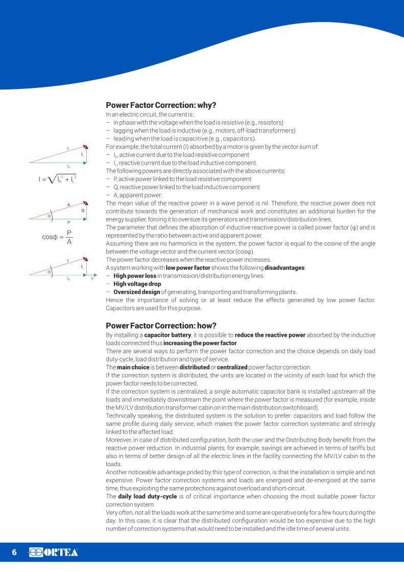
Power Factor Correction: why?In an electric circuit, the current is:
– in phase with the voltage when the load is resistive (e.g., resistors)
– lagging when the load is inductive (e.g., motors, off-load transformers)
– leading when the load is capacitive (e.g., capacitors).
For example, the total current (I) absorbed by a motor is given by the vector sum of:
– I , active current due to the load resistive componentR
– I , reactive current due to the load inductive component.L
The following powers are directly associated with the above currents:
– P, active power linked to the load resistive component
– Q, reactive power linked to the load inductive component
– A, apparent power.
The mean value of the reactive power in a wave period is nil. Therefore, the reactive power does not
contribute towards the generation of mechanical work and constitutes an additional burden for the
energy supplier, forcing it to oversize its generators and transmission/distribution lines.
The parameter that defines the absorption of inductive reactive power is called power factor (φ) and is
represented by the ratio between active and apparent power.
Assuming there are no harmonics in the system, the power factor is equal to the cosine of the angle
between the voltage vector and the current vector (cosφ).
The power factor decreases when the reactive power increases.
A system working with low power factor shows the following disadvantages:
– High power loss in transmission/distribution energy lines.
– High voltage drop.
– Oversized design of generating, transporting and transforming plants.
Hence the importance of solving or at least reduce the effects generated by low power factor.
Capacitors are used for this purpose.
Power Factor Correction: how?By installing a capacitor battery, it is possible to reduce the reactive power absorbed by the inductive
loads connected thus increasing the power factor.
There are several ways to perform the power factor correction and the choice depends on daily load
duty-cycle, load distribution and type of service.
The main choice is between distributed or centralized power factor correction.
If the correction system is distributed, the units are located in the vicinity of each load for which the
power factor needs to be corrected.
If the correction system is centralized, a single automatic capacitor bank is installed upstream all the
loads and immediately downstream the point where the power factor is measured (for example, inside
the MV/LV distribution transformer cabin on in the main distribution switchboard).
Technically speaking, the distributed system is the solution to prefer: capacitors and load follow the
same profile during daily service, which makes the power factor correction systematic and strongly
linked to the affected load.
Moreover, in case of distributed configuration, both the user and the Distributing Body benefit from the
reactive power reduction. In industrial plants, for example, savings are achieved in terms of tariffs but
also in terms of better design of all the electric lines in the facility connecting the MV/LV cabin to the
loads.
Another noticeable advantage prided by this type of correction, is that the installation is simple and not
expensive. Power factor correction systems and loads are energised and de-energised at the same
time, thus exploiting the same protections against overload and short-circuit.
The daily load duty-cycle is of critical importance when choosing the most suitable power factor
correction system.
Very often, not all the loads work at the same time and some are operative only for a few hours during the
day. In this case, it is clear that the distributed configuration would be too expensive due to the high
number of correction systems that would need to be installed and the idle time of several units.

7R
The distributed configuration is most efficient when the majority of the required reactive power is
concentrated on few high power loads working for many hours during the day.
The centralized configuration, on the other hand, is suitable for situations where there are many diverse
loads working sporadically. In this case, the bank power is much lower that the overall power that would
be necessary with a distributed configuration.
It is recommended to permanently connect the correction unit only if the daily reactive power
absorption is sufficiently regular, otherwise the unit must be handled in order to avoid the power factor
to swap to a leading value.
Should the reactive power absorption be very changeable during the plant operating time, it is
recommendable to choose an automatic correction system splitting the bank into several steps. The
manual operation can be foreseen only when the correction unit needs to be operated only a few times
during the day.
Power Factor Correction: how much?The choice of the capacitor bank power to install (Q ) depends directly on:C
– desired cosφ2 value
– starting cosφ1 value
– installed active power.
The formula is: Q = P x (tanφ1 - tanφ2)C
Q = capacitive reactive power to be installed (kvar)C
P = installed active power (kW)
Q ,Q ’ = inductive reactive power before and after the installation of the capacitor bankL L
A, A’= apparent power before and after the power factor correction.
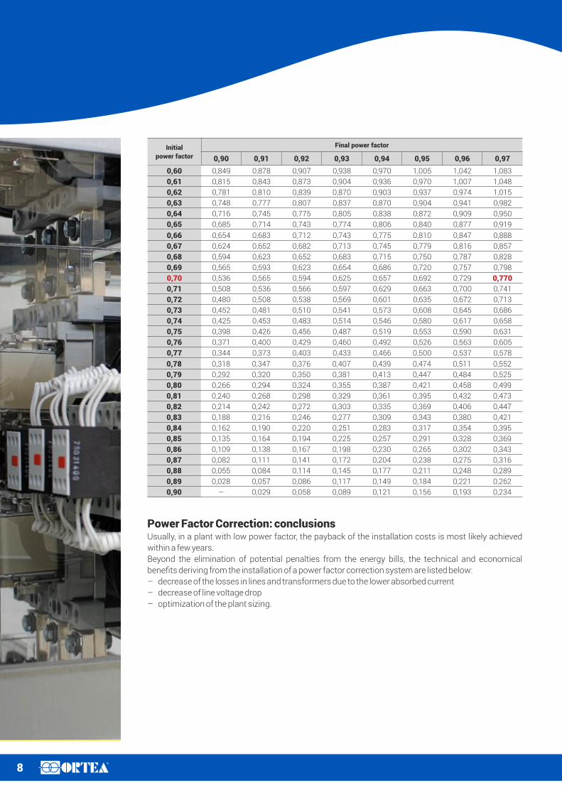
Said formula can also be written as: Q = k x PC
where k can be easily calculated with the table in the following page.
Example: assuming that the installed load absorbs an active power equal to 300kW with a starting
power factor equal to 0,70 and that an increase to 0,97 is desired, the coefficient k can be obtained from
table 1: k = 0,770. Q is therefore equal to: Q = 0,770 x 300 = 231kvarC C
Power Factor Correction: harmonics in electric linesCurrent distortion (i.e., harmonics) in industrial or tertiary electric plants is generated by non-linear
loads such as inverters, welders, rectifiers, computers, drives and so on. The distortion is represented by
the number THDI%: if the current is sinusoidal, the THDI% is nil. The more the current is distorted, the
higher is its THDI% value.
Their connection to the mains causes several problems in an electric system:
– Rotating machinery: generation of eddy torques (and consequent vibrations) that undermine the
mechanical structure. The loss increase causes undesired overheating and isolation damage.
– Transformers: increase of core and winding losses, with potential winding damage. The potential
presence of DC voltage or current components may saturate the magnetic core, thus increasing the
magnetizing current.
– Capacitors: overheating and voltage increase, both causing a reduction of the expected life.
If periodic, the waveform of the current generated by a non-linear load can be represented as the sum
of several sinusoidal waves at different frequency (the wave at 50Hz is called fundamental, whilst the
ones at frequency multiple of the fundamental are called harmonics).
It is generally not recommended to correct the power factor in a system with high harmonic content
without any device dealing with the harmonics.Even though capacitors able to withstand high
overloading could be provided, power factor correction performed only via capacitors actually
increases the harmonic disturbance and the related negative effects.
The best solution for this type of issue is the detuned filter obtained by connecting reactances in
series to the capacitors. The reactances shift the system resonance frequency below the lowest
existing harmonic thus protecting the capacitors and avoiding dangerous resonance phenomena.
φ2
φ1
A
A’
QL
Q ’L
QC
P
8R
Initial
power factor
Final power factor
0,90 0,91 0,92 0,93 0,94 0,95 0,96 0,97
0,60 0,849 0,878 0,907 0,938 0,970 1,005 1,042 1,083
0,61 0,815 0,843 0,873 0,904 0,936 0,970 1,007 1,048
0,62 0,781 0,810 0,839 0,870 0,903 0,937 0,974 1,015
0,63 0,748 0,777 0,807 0,837 0,870 0,904 0,941 0,982
0,64 0,716 0,745 0,775 0,805 0,838 0,872 0,909 0,950
0,65 0,685 0,714 0,743 0,774 0,806 0,840 0,877 0,919
0,66 0,654 0,683 0,712 0,743 0,775 0,810 0,847 0,888
0,67 0,624 0,652 0,682 0,713 0,745 0,779 0,816 0,857
0,68 0,594 0,623 0,652 0,683 0,715 0,750 0,787 0,828
0,69 0,565 0,593 0,623 0,654 0,686 0,720 0,757 0,798
0,70 0,536 0,565 0,594 0,625 0,657 0,692 0,729 0,770
0,71 0,508 0,536 0,566 0,597 0,629 0,663 0,700 0,741
0,72 0,480 0,508 0,538 0,569 0,601 0,635 0,672 0,713
0,73 0,452 0,481 0,510 0,541 0,573 0,608 0,645 0,686
0,74 0,425 0,453 0,483 0,514 0,546 0,580 0,617 0,658
0,75 0,398 0,426 0,456 0,487 0,519 0,553 0,590 0,631
0,76 0,371 0,400 0,429 0,460 0,492 0,526 0,563 0,605
0,77 0,344 0,373 0,403 0,433 0,466 0,500 0,537 0,578
0,78 0,318 0,347 0,376 0,407 0,439 0,474 0,511 0,552
0,79 0,292 0,320 0,350 0,381 0,413 0,447 0,484 0,525
0,80 0,266 0,294 0,324 0,355 0,387 0,421 0,458 0,499
0,81 0,240 0,268 0,298 0,329 0,361 0,395 0,432 0,473
0,82 0,214 0,242 0,272 0,303 0,335 0,369 0,406 0,447
0,83 0,188 0,216 0,246 0,277 0,309 0,343 0,380 0,421
0,84 0,162 0,190 0,220 0,251 0,283 0,317 0,354 0,395
0,85 0,135 0,164 0,194 0,225 0,257 0,291 0,328 0,369
0,86 0,109 0,138 0,167 0,198 0,230 0,265 0,302 0,343
0,87 0,082 0,111 0,141 0,172 0,204 0,238 0,275 0,316
0,88 0,055 0,084 0,114 0,145 0,177 0,211 0,248 0,289
0,89 0,028 0,057 0,086 0,117 0,149 0,184 0,221 0,262
0,90 – 0,029 0,058 0,089 0,121 0,156 0,193 0,234
Power Factor Correction: conclusionsUsually, in a plant with low power factor, the payback of the installation costs is most likely achieved
within a few years.
Beyond the elimination of potential penalties from the energy bills, the technical and economical
benefits deriving from the installation of a power factor correction system are listed below:
– decrease of the losses in lines and transformers due to the lower absorbed current
– decrease of line voltage drop
– optimization of the plant sizing.
9R
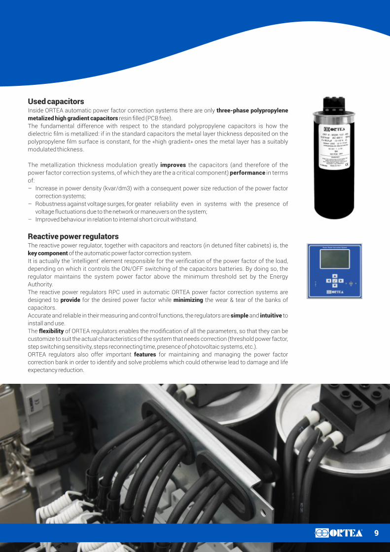
Used capacitorsInside ORTEA automatic power factor correction systems there are only three-phase polypropylene
metalized high gradient capacitors resin filled (PCB free).
The fundamental difference with respect to the standard polypropylene capacitors is how the
dielectric film is metallized: if in the standard capacitors the metal layer thickness deposited on the
polypropylene film surface is constant, for the «high gradient» ones the metal layer has a suitably
modulated thickness.
The metallization thickness modulation greatly improves the capacitors (and therefore of the
power factor correction systems, of which they are the a critical component) performance in terms
of:
– Increase in power density (kvar/dm3) with a consequent power size reduction of the power factor
correction systems;
– Robustness against voltage surges, for g eater reliability even in systems with the presence of
voltage fluctuations due to the network or maneuvers on the system;
– Improved behaviour in relation to internal short circuit withstand.
Reactive power regulatorsThe reactive power regulator, together with capacitors and reactors (in detuned filter cabinets) is, the
key component of the automatic power factor correction system.
It is actually the 'intelligent' element responsible for the verification of the power factor of the load,
depending on which it controls the ON/OFF switching of the capacitors batteries. By doing so, the
regulator maintains the system power factor above the minimum threshold set by the Energy
Authority.
The reactive power regulators RPC used in automatic ORTEA power factor correction systems are
designed to provide for the desired power factor while minimizing the wear & tear of the banks of
capacitors.
Accurate and reliable in their measuring and control functions, the regulators are simple and intuitive to
install and use.
The flexibility of ORTEA regulators enables the modification of all the parameters, so that they can be
customize to suit the actual characteristics of the system that needs correction (threshold power factor,
step switching sensitivity, steps reconnecting time, presence of photovoltaic systems, etc.).
ORTEA regulators also offer important features for maintaining and managing the power factor
correction bank in order to identify and solve problems which could otherwise lead to damage and life
expectancy reduction.
10R
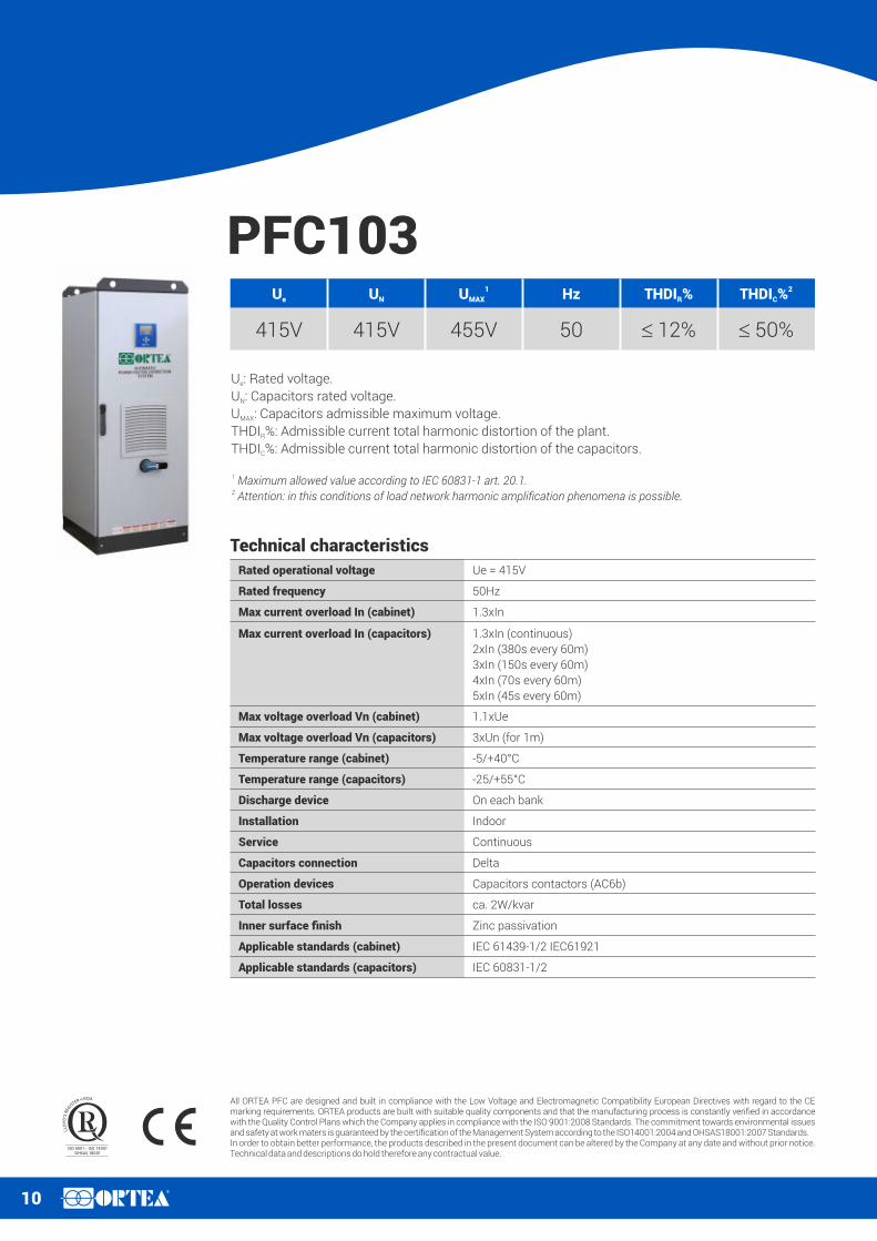
PFC103
U : Rated voltage.e
U : Capacitors rated voltage.N
U : Capacitors admissible maximum voltage.MAX
THDI %: Admissible current total harmonic distortion of the plant.R
THDI %: Admissible current total harmonic distortion of the capacitors.C
Ue UN
1UMAX Hz THDI %R
2THDI %C
415V 415V 455V 50 £ 12% £ 50%
Technical characteristics
Rated operational voltage Ue = 415V
Rated frequency 50Hz
Max current overload In (cabinet) 1.3xIn
Max current overload In (capacitors) 1.3xIn (continuous)
2xIn (380s every 60m)
3xIn (150s every 60m)
4xIn (70s every 60m)
5xIn (45s every 60m)
Max voltage overload Vn (cabinet) 1.1xUe
Max voltage overload Vn (capacitors) 3xUn (for 1m)
Temperature range (cabinet) -5/+40°C
Temperature range (capacitors) -25/+55°C
Discharge device On each bank
Installation Indoor
Service Continuous
Capacitors connection Delta
Operation devices Capacitors contactors (AC6b)
Total losses ca. 2W/kvar
Inner surface finish Zinc passivation
Applicable standards (cabinet) IEC 61439-1/2 IEC61921
Applicable standards (capacitors) IEC 60831-1/2
1 Maximum allowed value according to IEC 60831-1 art. 20.1.2 Attention: in this conditions of load network harmonic amplification phenomena is possible.
All ORTEA PFC are designed and built in compliance with the Low Voltage and Electromagnetic Compatibility European Directives with regard to the CE marking requirements. ORTEA products are built with suitable quality components and that the manufacturing process is constantly verified in accordance with the Quality Control Plans which the Company applies in compliance with the ISO 9001:2008 Standards. The commitment towards environmental issues and safety at work maters is guaranteed by the certification of the Management System according to the ISO14001:2004 and OHSAS18001:2007 Standards.In order to obtain better performance, the products described in the present document can be altered by the Company at any date and without prior notice. Technical data and descriptions do hold therefore any contractual value.
11R
Type Power
[kvar]
Steps
[no.]
Steps size
[kvar]
Load-break
switch
[A]
Icc
[kA]
Regulators Fan
[no.]
IP21 cabinet
WxDxH (type)
[mm]
Weight
[Kg]
PFC103-100 100 8 2x12.5-25-50 250 17 RPC 5LGA 1 410x680x1200 (23) 80
PFC103-150 150 12 2x12.5-25-2x50 400 25 RPC 8BGA 2 600x600x1600 (31) 120
PFC103-200 200 16 2x12.5-25-3x50 630 25 RPC 8BGA 2 600x600x1600 (31) 135
PFC103-250 250 20 2x12.5-25-2x50-100 630 25 RPC 8BGA 3 600x600x2000 (32) 170
PFC103-300 300 24 2x12.5-25-50-75-125 800 35 RPC 8BGA 3 600x600x2000 (32) 185
PFC103-350 350 28 12.5-25-37.5-50-100-125 800 35 RPC 8BGA 2 800x600x2000 (33) 210
PFC103-400 400 32 12.5-25-37.5-75-100-150 1000 35 RPC 8BGA 2 800x600x2000 (33) 220
PFC103-450 450 36 12.5-25-37.5-75-100-200 1000 35 RPC 8BGA 2 800x600x2000 (33) 230
PFC103-500 500 20 2x25-50-2x100-200 2x630 25 RPC 8BGA 3+3 2x(600x600x2000)(2x32) 340
PFC103-600 600 24 2x25-50-100-150-250 2x800 35 RPC 8BGA 3+3 2x(600x600x2000)(2x32) 370
PFC103-700 700 28 25-50-75-100-200-250 2x800 35 RPC 8BGA 2+2 2x(800x600x2000)(2x33) 420
PFC103-800 800 32 25-50-75-150-200-300 2x1000 35 RPC 8BGA 2+2 2x(800x600x2000)(2x33) 440
PFC103-900 900 36 25-50-75-150-200-400 2x1000 35 RPC 8BGA 2+2 2x(800x600x2000)(2x33) 460
PFC103-1000 1000 28 37.5-75-112.5-150-300-375 3x800 35 RPC 8BGA 2+2+2 3x(800x600x2000)(3x33) 630
For higher powers, two or more PFC units of the same size can be connected in parallel, using the characteristic of the regulator to act as «master/slave».
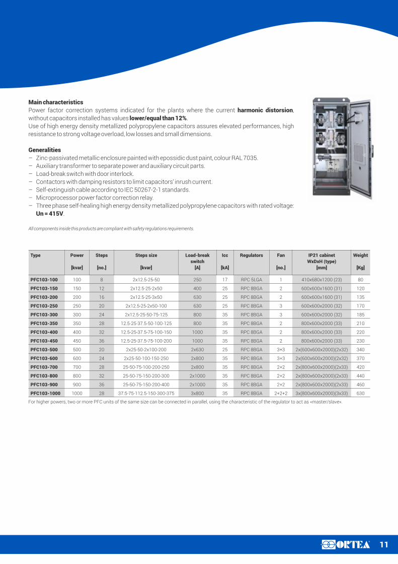
Main characteristics
Power factor correction systems indicated for the plants where the current harmonic distorsion,
without capacitors installed has values lower/equal than 12%.
Use of high energy density metallized polypropylene capacitors assures elevated performances, high
resistance to strong voltage overload, low losses and small dimensions.
Generalities
– Zinc-passivated metallic enclosure painted with epossidic dust paint, colour RAL 7035.
– Auxiliary transformer to separate power and auxiliary circuit parts.
– Load-break switch with door interlock.
– Contactors with damping resistors to limit capacitors’ inrush current.
– Self-extinguish cable according to IEC 50267-2-1 standards.
– Microprocessor power factor correction relay.
– Three phase self-healing high energy density metallized polypropylene capacitors with rated voltage:
Un = 415V.
All components inside this products are compliant with safety regulations requirements.

12R
PFC503Ue UN
1UMAX Hz THDI %R
2THDI %C
415V 525V 577V 50 £ 27% £ 85%
U : Rated voltage.e
U : Capacitors rated voltage.N
U : Capacitors admissible maximum voltage.MAX
THDI %: Admissible current total harmonic distortion of the plant.R
THDI %: Admissible current total harmonic distortion of the capacitors.C
Technical characteristics
Rated operational voltage Ue = 415V
Rated frequency 50Hz
Max current overload In (cabinet) 1.3xIn
Max current overload In (capacitors) 1.3xIn (continuous)
2xIn (380s every 60m)
3xIn (150s every 60m)
4xIn (70s every 60m)
5xIn (45s every 60m)
Max voltage overload Vn (cabinet) 1.1xUe
Max voltage overload Vn (capacitors) 3xUn (for 1m)
Temperature range (cabinet) -5/+40°C
Temperature range (capacitors) -25/+55°C
Discharge device On each bank
Installation Indoor
Service Continuous
Capacitors connection Delta
Operation devices Capacitors contactors (AC6b)
Total losses ca. 2W/kvar
Inner surface finish Zinc passivation
Applicable standards (cabinet) IEC 61439-1/2 IEC61921
Applicable standards (capacitors) IEC 60831-1/2
1 Maximum allowed value according to IEC 60831-1 art. 20.1.2 Attention: in this conditions of load network harmonic amplification phenomena is possible.
All ORTEA PFC are designed and built in compliance with the Low Voltage and Electromagnetic Compatibility European Directives with regard to the CE marking requirements. ORTEA products are built with suitable quality components and that the manufacturing process is constantly verified in accordance with the Quality Control Plans which the Company applies in compliance with the ISO 9001:2008 Standards. The commitment towards environmental issues and safety at work maters is guaranteed by the certification of the Management System according to the ISO14001:2004 and OHSAS18001:2007 Standards.In order to obtain better performance, the products described in the present document can be altered by the Company at any date and without prior notice. Technical data and descriptions do hold therefore any contractual value.

13R
Type Power
[kvar]
Steps
[no.]
Steps size
[kvar]
Load-break
switch
[A]
Icc
[kA]
Regulators Fan
[no.]
IP21 cabinet
WxDxH (type)
[mm]
Weight
[Kg]
PFC503-100 100 8 2x12.5-25-50 250 17 RPC 8BGA 2 600x600x1600 (31) 85
PFC503-150 150 12 2x12.5-25-2x50 400 25 RPC 8BGA 2 600x600x1600 (31) 125
PFC503-200 200 16 2x12.5-25-3x50 630 25 RPC 8BGA 2 600x600x1600 (31) 140
PFC503-250 250 20 2x12.5-25-2x50-100 630 25 RPC 8BGA 3 600x600x2000 (32) 180
PFC503-300 300 24 2x12.5-25-50-75-125 800 35 RPC 8BGA 3 600x600x2000 (32) 195
PFC503-350 350 28 12.5-25-37.5-50-100-125 800 35 RPC 8BGA 2 800x600x2000 (33) 220
PFC503-400 400 32 12.5-25-37.5-75-100-150 1000 35 RPC 8BGA 2 800x600x2000 (33) 230
PFC503-450 450 36 12.5-25-37.5-75-100-200 1000 35 RPC 8BGA 2 800x600x2000 (33) 245
PFC503-500 500 20 2x25-50-2x100-200 2x630 25 RPC 8BGA 3+3 2x(600x600x2000)(2x32) 360
PFC503-600 600 24 2x25-50-100-150-250 2x800 35 RPC 8BGA 3+3 2x(600x600x2000)(2x32) 390
PFC503-700 700 28 25-50-75-100-200-250 2x800 35 RPC 8BGA 2+2 2x(800x600x2000)(2x33) 440
PFC503-800 800 32 25-50-75-150-200-300 2x1000 35 RPC 8BGA 2+2 2x(800x600x2000)(2x33) 460
PFC503-900 900 36 25-50-75-150-200-400 2x1000 35 RPC 8BGA 2+2 2x(800x600x2000)(2x33) 490
PFC503-1000 1000 28 37.5-75-112.5-150-300-375 3x800 35 RPC 8BGA 2+2+2 3x(800x600x2000)(3x33) 660
Main characteristics
Power factor correction systems indicated for the plants where the current harmonic distorsion,
without capacitors installed has values lower/equal than 27%.
Use of high energy density metallized polypropylene capacitors assures elevated performances, high
resistance to strong voltage overload, low losses and small dimensions.
Generalities
– Zinc-passivated metallic enclosure painted with epossidic dust paint, colour RAL 7035.
– Auxiliary transformer to separate power and auxiliary circuit parts.
– Load-break switch with door interlock.
– Contactors with damping resistors to limit capacitors’ inrush current.
– Self-extinguish cable according to IEC 50267-2-1 standards.
– Microprocessor power factor correction relay.
– Three phase self-healing high energy density metallized polypropylene capacitors with rated voltage:
Un = 525V.
All components inside this products are compliant with safety regulations requirements.
For higher powers, two or more PFC units of the same size can be connected in parallel, using the characteristic of the regulator to act as «master/slave».

14R
PHF203Ue UN
1UMAX Hz THDI %R Detuning choke (180Hz)
415V 525V 577V 50 > 27% 100% non linear load in network
U : Rated voltage.e
U : Capacitors rated voltage.N
U : Capacitors admissible maximum voltage.MAX
THDI %: Admissible current total harmonic distortion of the plant.R
Technical characteristics
Rated operational voltage Ue = 415V
Rated frequency 50Hz
Max current overload In (cabinet) 1.3xIn
Max current overload In (capacitors) 1.3xIn (continuous)
2xIn (380s every 60m)
3xIn (150s every 60m)
4xIn (70s every 60m)
5xIn (45s every 60m)
Max voltage overload Vn (cabinet) 1.1xUe
Max voltage overload Vn (capacitors) 3xUn (for 1m)
Temperature range (cabinet) -5/+40°C
Temperature range (capacitors) -25/+55°C
Discharge device On each bank
Installation Indoor
Service Continuous
Capacitors connection Delta
Operation devices Capacitors contactors
Total losses ca. 6W/kvar
Inner surface finish Zinc passivation
Applicable standards (cabinet) IEC 61439-1/2 IEC61921 IEC61642
Applicable standards (capacitors) IEC 60831-1/2
1 Maximum allowed value according to IEC 60831-1 art. 20.1.
All ORTEA PFC are designed and built in compliance with the Low Voltage and Electromagnetic Compatibility European Directives with regard to the CE marking requirements. ORTEA products are built with suitable quality components and that the manufacturing process is constantly verified in accordance with the Quality Control Plans which the Company applies in compliance with the ISO 9001:2008 Standards. The commitment towards environmental issues and safety at work maters is guaranteed by the certification of the Management System according to the ISO14001:2004 and OHSAS18001:2007 Standards.In order to obtain better performance, the products described in the present document can be altered by the Company at any date and without prior notice. Technical data and descriptions do hold therefore any contractual value.

15R
Type Power
[kvar]
Steps
[no.]
Steps size
[kvar]
Banks
[kvar]
Load-break
switch
[A]
Icc
[kA]
Regulators Fan
[no.]
IP21 cabinet
WxDxH (type)
[mm]
Weight
[Kg]
PHF203-100 100 8 2x12.5-25-50 25-2x50 250 17 RPC 8BGA 3 600x600x2000 (32) 200
PHF203-150 150 12 2x12.5-25-2x50 25-50-75 400 25 RPC 8BGA 2 800x600x2000 (33) 240
PHF203-200 200 8 2x25-3x50 50-2x75 630 25 RPC 8BGA 2 800x600x2000 (33) 300
PHF203-250 250 10 2x25-4x50 50-2x100 630 25 RPC 8BGA 2 800x600x2000 (33) 430
PHF203-300 300 6 6x50 3x100 800 35 RPC 8BGA 2 800x600x2000 (33) 500
PHF203-400 400 8 2x50-3x100 100-2x150 2x630 25 RPC 8BGA 2+2 2x(800x600x2000)(2x33) 600
PHF203-500 500 10 2x50-4x100 100-2x200 2x630 25 RPC 8BGA 2+2 2x(800x600x2000)(2x33) 860
PHF203-600 600 6 6x100 3x200 2x800 35 RPC 8BGA 2+2 2x(800x600x2000)(2x33) 1000
PHF203-750 700 10 2x75-4x150 3x50-6x100 2x630 25 RPC 8BGA 2+2+2 3x(800x600x2000)(3x33) 1290
PHF203-800 800 6 6x150 9x100 3x800 35 RPC 8BGA 2+2+2 3x(800x600x2000)(3x33) 1500
PHF203-1000 1000 10 2x100-4x200 4x50-8x100 4x630 25 RPC 8BGA 2+2+2+2 4x(800x600x2000)(4x33) 1720
Main characteristics
Power factor correction systems indicated for the plants where the current harmonic distorsion,
without capacitors installed has values higher than 27%.
Use of high energy density metallized polypropylene capacitors assures elevated performances, high
resistance to strong voltage overload, low losses and small dimensions.
Generalities
– Zinc-passivated metallic enclosure painted with epossidic dust paint, colour RAL 7035.
– Auxiliary transformer to separate power and auxiliary circuit parts.
– Load-break switch with door interlock.
– Special contactors for capacitive loads.
– Self-extinguish cable according to IEC 50267-2-1 standards.
– Microprocessor power factor correction relay.
– Three phase self-healing high energy density metallized polypropylene capacitors with rated voltage:
Un = 525V.
– Three-phase detuning chokes with tuning frequency 180Hz.
All components inside this products are compliant with safety regulations requirements.
For higher powers, two or more PFC units of the same size can be connected in parallel, using the characteristic of the regulator to act as «master/slave».

16R
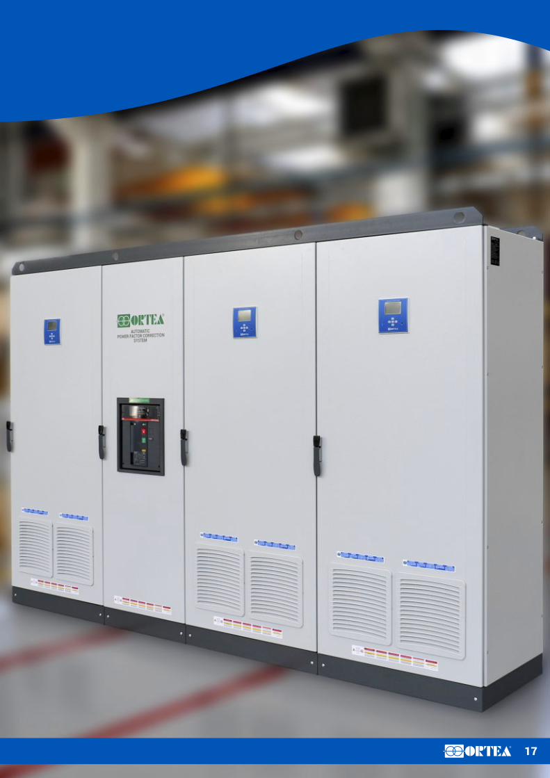
Custom productsFor high rating units, beyond the 'master - slave' configuration which exploits the controller ability to
connect in parallel several units, ORTEA can develop very quickly automatic power factor correction
systems personalized on the Customer's specification. All this thanks to ORTEA's flexible and
responsive organization.
These units are assembled inside a single industrial cabinet and are fitted with a single switch
disconnect instead of the traditional switches mounted on each parallel module.
Among other characteristics, it is possible to design the unit with special step-sizes, input automatic
circuit breakers, different paint colour and higher IP protection (up to IP55).
17R

18R

19R
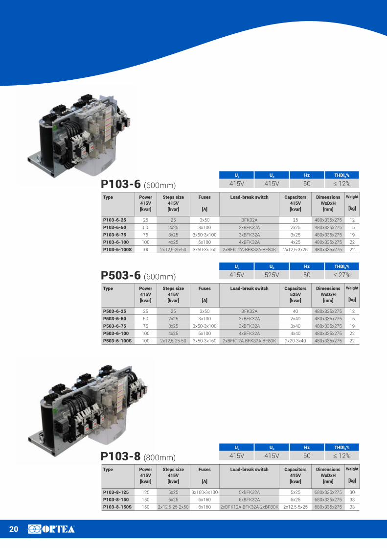
RacksDesigned to suit the most common switchboard sizes, ORTEA's rack system is the ideal solution for
OEM and switchboard manufacturers. The rack is:
– Compact
– Available with or without blocking reactor
– Available in a single rack from 9.4kvar to 150kvar
– Fitted with busbars sized to withstand up to 400kvar
– Easy to assemble (busbars and NH fuses incorporated in the rack support)
ORTEA racks are fitted with three-phase self-regenerating high energy-density metallised polypropylene
capacitors ensuring enhanced performance, low losses and contained dimensions.
The lateral adjustable slides allow for quick and easy assembling operations inside any cabinets.
Thanks to its extensible brackets, the 480mm rack can be mounted in a 800mm cabinet thus enabling a
flexible combination of sizes and total reactive power.
The busbar system can withstand a maximum reactive power equal to 400kvar (at 415V, 50Hz).
Rack can be added to the system at any time.
Each auxiliary and control component is supplied already wired to the terminal block assembled on the
rack.
Standard features
Each rack is supplied complete with:
– Contactors for capacitors
– Self-extinguishing cables (EN50267-2-1)
– Three-pole NH00 fuse holder
– NH00 gG power fuses
– Three-phase self-regenerating high energy-density metallised polypropylene capacitors
– Three-phase connecting system via tinned copper bars
– Discharging resistors
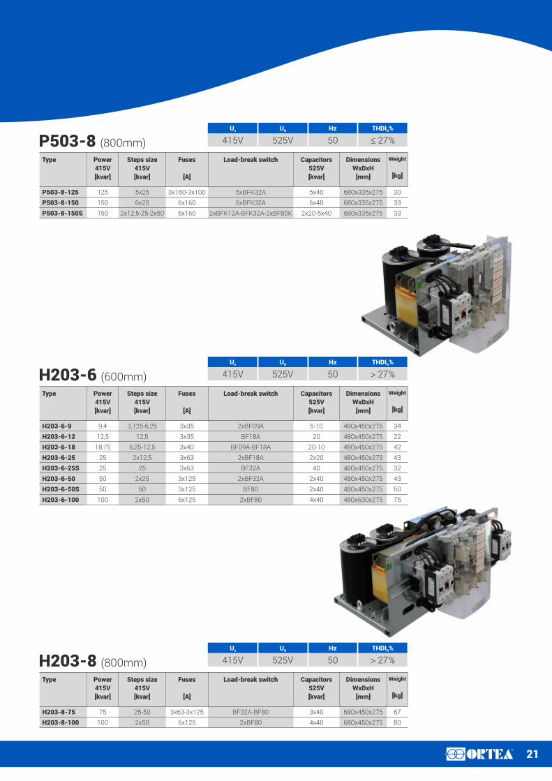
– Only for the H203 type, blocking reactor with 180Hz tuning frequency
All the components conform with the safety legislative provisions.
Standard accessories (in every rack)
– Telescopic side brackets, suitable for 600-400mm deep cabinets
– Tinned copper connection bars, complete with bolts
– IP20 Plexiglass protection
– Adapting brackets for installation inside cabinet with different width (800-1000mm)
The P103 rack technical characteristics are the same as the ones valid for the PFC103 automatic power factor correction systems. The same
applies for P503 racks (PFC503) and H203 (PHF203).
20R
Type Power
415V
[kvar]
Steps size
415V
[kvar]
Fuses
[A]
Load-break switch Capacitors
415V
[kvar]
Dimensions
WxDxH
[mm]
Weight
[kg]
P103-8-125 125 5x25 3x160-3x100 5xBFK32A 5x25 680x335x275 30
P103-8-150 150 6x25 6x160 6xBFK32A 6x25 680x335x275 33
P103-8-150S 150 2x12,5-25-2x50 6x160 2xBFK12A-BFK32A-2xBF80K 2x12,5-5x25 680x335x275 33
P103-8 (800mm)
Ue UN Hz THDI %R
415V 415V 50 £ 12%
Type Power
415V
[kvar]
Steps size
415V
[kvar]
Fuses
[A]
Load-break switch Capacitors
415V
[kvar]
Dimensions
WxDxH
[mm]
Weight
[kg]
P103-6-25 25 25 3x50 BFK32A 25 480x335x275 12
P103-6-50 50 2x25 3x100 2xBFK32A 2x25 480x335x275 15
P103-6-75 75 3x25 3x50-3x100 3xBFK32A 3x25 480x335x275 19
P103-6-100 100 4x25 6x100 4xBFK32A 4x25 480x335x275 22
P103-6-100S 100 2x12,5-25-50 3x50-3x160 2xBFK12A-BFK32A-BF80K 2x12,5-3x25 480x335x275 22
P103-6 (600mm)
Ue UN Hz THDI %R
415V 415V 50 £ 12%
Type Power
415V
[kvar]
Steps size
415V
[kvar]
Fuses
[A]
Load-break switch Capacitors
525V
[kvar]
Dimensions
WxDxH
[mm]
Weight
[kg]
P503-6-25 25 25 3x50 BFK32A 40 480x335x275 12
P503-6-50 50 2x25 3x100 2xBFK32A 2x40 480x335x275 15
P503-6-75 75 3x25 3x50-3x100 3xBFK32A 3x40 480x335x275 19
P503-6-100 100 4x25 6x100 4xBFK32A 4x40 480x335x275 22
P503-6-100S 100 2x12,5-25-50 3x50-3x160 2xBFK12A-BFK32A-BF80K 2x20-3x40 480x335x275 22
P503-6 (600mm)
Ue UN Hz THDI %R
415V 525V 50 £ 27%
21R
Type Power
415V
[kvar]
Steps size
415V
[kvar]
Fuses
[A]
Load-break switch Capacitors
525V
[kvar]
Dimensions
WxDxH
[mm]
Weight
[kg]
P503-8-125 125 5x25 3x160-3x100 5xBFK32A 5x40 680x335x275 30
P503-8-150 150 6x25 6x160 6xBFK32A 6x40 680x335x275 33
P503-8-150S 150 2x12,5-25-2x50 6x160 2xBFK12A-BFK32A-2xBF80K 2x20-5x40 680x335x275 33
P503-8 (800mm)
Ue UN Hz THDI %R
415V 525V 50 £ 27%
Type Power
415V
[kvar]
Steps size
415V
[kvar]
Fuses
[A]
Load-break switch Capacitors
525V
[kvar]
Dimensions
WxDxH
[mm]
Weight
[kg]
H203-6-9 9,4 3,125-6,25 3x35 2xBF09A 5-10 480x450x275 34
H203-6-12 12,5 12,5 3x35 BF18A 20 480x450x275 22
H203-6-18 18,75 6,25-12,5 3x40 BF09A-BF18A 20-10 480x450x275 42
H203-6-25 25 2x12,5 3x63 2xBF18A 2x20 480x450x275 43
H203-6-25S 25 25 3x63 BF32A 40 480x450x275 32
H203-6-50 50 2x25 3x125 2xBF32A 2x40 480x450x275 43
H203-6-50S 50 50 3x125 BF80 2x40 480x450x275 50
H203-6-100 100 2x50 6x125 2xBF80 4x40 480x630x275 75
H203-6 (600mm)
Ue UN Hz THDI %R
415V 525V 50 > 27%
Type Power
415V
[kvar]
Steps size
415V
[kvar]
Fuses
[A]
Load-break switch Capacitors
525V
[kvar]
Dimensions
WxDxH
[mm]
Weight
[kg]
H203-8-75 75 25-50 3x63-3x125 BF32A-BF80 3x40 680x450x275 67
H203-8-100 100 2x50 6x125 2xBF80 4x40 680x450x275 80
H203-8 (800mm)
Ue UN Hz THDI %R
415V 525V 50 > 27%

22R
R
ahead of time
Experience.In its over 45 years of business, Ortea (founded in 1969) has gained experience and know-how that enabled continuous growth and evolution. This never-ending process has allowed the Company to assume a leading role worldwide in designing and manufacturing voltage stabilisers.
Reliability.Thanks also to its long-established Quality System, ORTEA can ensure the production of reliable and long lasting products, each one of them accurately tested.
Flexibility.In addition to the standard production, ORTEA's extremely flexible organization is able to develop and manufacture cost-effective special equipment based on the Customer's specification.
Research & Development.ORTEA invests a considerable amount in R&D concerning new products and technology. It is acknowledged that modern challenges in a globalised and competitive market can be won only when you're «ahead of time».
Synergy.Co-operation between Headquarters, Subsidiaries, Distributors and Customers aimed at a careful analysis of markets and demand enable ORTEA the development of up-to-date products.By working together, marketing, design, production and after-sales service allow the Company to meet the necessities set forth by an increasingly globalised and competitive market.
After-sales.The continuous monitoring and analysis of requests and claims carried out by the after-sales service enables the improvement the quality of both products and service to the Customer.ORTEA after-sales organization can act quickly, providing for precise issue analysis, supply of advise and know-how and , if necessary, provision of spare parts in order to solve any anomaly.
Speed.ORTEA can manage the purchasing orders very quickly. Review of offer/order, design, production planning, manufacturing and strict test routines: all the processes have been analysed and optimised in order to eliminate idle time and shorten delivery terms.
Quality.Aiming at providing for the best quality, the manufacturing process includes checks during production and detail test sessions for each stabiliser.The approved Integrated Managing System ensures the control of every manufacturing phase, starting from checking the components at reception and ending with the best package in relation to the transport type.The Integrated Managing System is ISO9001:2008 – ISO14001:2004 – OHSAS18001:2007 approved.

1.1 WarrantyThe purchased equipment is under warranty against any material or workmanship defects that might occurs within the terms indicated in the following starting from the date of purchase and for all mechanical, electrical and electronic parts. During the warranty period, the Manufacturer will repair or replace any defective parts, unless said defects are due to:– improper handling, storage and/or use:– wear & tear resulting from normal usage;– incompetence or negligence on the Buyer’s side when installing,
running and maintaining the unit;– interventions performed by or on behalf of the Buyer without written
authorization;– failure to comply with instructions given by the Manufacturer;– removal, alteration or forgery of the nameplate and the data
indicated thereof; and– fortuitous or force majeure events such as (but not limited to) fire,
earthquake, flood, riot and revolution, war, political instability, terroristic act, strike, etc.).
Moreover, the provided warranty will immediately become null and void in case of:– failure to comply with the payment terms;– failure to carry out routine and / or extraordinary maintenance;– improper use of the equipment; and– external phenomena beyond the unit’s scope and control.In case of failure, the Buyer shall contact the Head Office where the Manufacturer will decide whether the repair can be performed on location, or if the equipment has to be shipped to the Manufacturer's facilities or to an after-sale Service Centre authorised by the Manufacturer.If the repairing intervention can be performed at the Buyer’s facility, all the expenses relevant to travelling, boarding and lodging of the Seller personnel shall be at the Buyer’s charge, whilst spare parts and labour costs shall be at the Manufacturer’s charge. However, the Buyer shall produce copy of the purchasing document (invoice) and report the detected anomaly prior to the intervention.If the intervention is performed at the Manufacturer's facility, the equipment shall be duly packed and shipped back at the Buyer’s expense and risk. The shipment after the repairing operations shall be under the Manufacturer’s responsibility.Unless otherwise agreed upon in writing, this warranty does not cover the replacement of the entire equipment under no circumstances whatsoever. Nothing shall be due to the Buyer for the time in which the equipment is left idle. The Buyer may not claim any compensations and/or reimbursements for expenses or indirect damages caused by the equipment failure.Parts provided as spare parts and/or replacements are subject to the same warranty terms. Repair or replacement of a defective part does not extend the original warranty period on the product as a whole.The competent place of jurisdiction for any disputes is in Monza (Italy).
1.2 Proper useWhile the unit is functioning, the operator must be protected from any risks associated with the functioning mode. The proper / correct use of the equipment allows for full exploitation of its characteristics in complete safety. For such purpose:– follow the instructions in the user manual;– check the integrity of equipment and components;– comply with instructions and warnings provided;– check status of preservation and keep maintenance on the
equipment under control;– check the status of cables and electrical connections;– comply with the nameplate data such as (but not limited to) power,
voltage and amperage;– use the equipment for the purpose intended by the Manufacturer;– operate the equipment in the environmental conditions for which it
was designed;– cut off the power supply in case of inspection, repair and
maintenance; – use suitable work clothing and personal protective equipment
(PPE); – immediately report any malfunction (bad behaviour, suspicion of
rupture, incorrect movement and noise beyond the standard level) to the department manager and switch off the equipment;
– comply with the recommended maintenance frequency, recording every control and comment related to the performed intervention.
1.3 Misuse / Improper useThe Manufacturer defines as «misuse / improper use» of the equipment any other than what described in the previous paragraph and in addition to that:– modification of the operating parameters. Should it be necessary to
make any modification to the equipment, the Buyer shall contact the Manufacturer;
– use of unsuitable or inadequate energy sources;– employment of not adequately trained/skilled personnel to run the
unit;– failure to comply with the maintenance instructions or
maintenance incorrectly carried out;– use of non-original spare parts or unsuitable ones; – modification and / or tapering with the equipment safety devices;– performance of control operations, maintenance, or repairs without
having first disconnected the energy supply;– performance of temporary repairs or remedial measures not
complying with the instructions.
WARNING. The Manufacturer declines all responsibility for damage to persons or belongings due to improper use as defined above.
1.4 Warranty terms24 months from invoice date.
Warranty terms
The present document is reserved property of ORTEA SpA:
it is compulsory to inform head office and ask for authorisation before proceeding with any release or reproduction. ORTEA SpA will not be held liable or responsible in any way for unauthorised copies,
alterations or additions to the text or to the illustrated parts of this document. Any modification involving company logo, certification symbols, names and official data is strictly forbidden.
In order to obtain better performance, ORTEA SpA reserves also the right to alter the products described in this document at any date and without prior notice. Technical data and descriptions do not
therefore have any contractual value.
Distributed by: EMMIS S.A.
Official Distributor in Greece, Cyprus, Bulgaria, FYROM 11 Andrea Metaxa Str., 145 64 Kifisia, Athens – GREECE
Tel: +30 210 3460222 – Fax: +30 210 3460562 Email: [email protected], www.emmismarine.com