PRODUCT CATALOGUE 2012 DGO - דף הבית - Madan …€¦ · · 2017-07-19Set of standard...
16
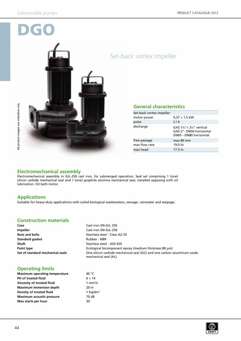
44 DGO 40 °C 6 ÷ 14 1 mm 2 /s 20 m 1 Kg/dm 3 70 dB 30 submersible pumps PRODUCT CATALOGUE 2012 Electromechanical assembly Applications Construction materials Operating limits Maximum operating temperature PH of treated fluid Viscosity of treated fluid Maximum immersion depth Density of treated fluid Maximum acoustic pressure Max starts per hour Cast iron EN-GJL 250 Cast iron EN-GJL-250 Stainless steel - Class A2-70 Rubber - NBR Stainless steel - AISI 420 One silicon carbide mechanical seal (SiC) and one carbon-aluminium oxide mechanical seal (AL) Suitable for heavy-duty applications with soiled biological wastewaters, sewage, rainwater and seepage. Electromechanical assembly in GJL-250 cast iron, for submerged operation. Seal set comprising 1 (one) silicon carbide mechanical seal and 1 (one) graphite alumina mechanical seal, installed opposing with oil lubrication. Oil bath motor. Case Impeller Nuts and bolts Standard gasket Shaft Set of standard mechanical seals Set-back vortex impeller General characteristics GAS 1½”÷ 2½” vertical GAS 2”- DN50 horizontal DN65 - DN80 horizontal Set-back vortex impeller Ecological bicomponent epoxy (medium thickness 80 μm) Paint type motor power poles discharge free passage max flow rate max head 19.0 l/s 17.3 m 0,37 ÷ 1,5 kW 2 / 4 max 80 mm All product images are indicative only
Transcript of PRODUCT CATALOGUE 2012 DGO - דף הבית - Madan …€¦ · · 2017-07-19Set of standard...
44
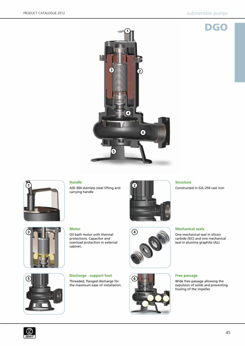
DGO
40 °C
6 ÷ 14
1 mm2/s
20 m
1 Kg/dm3
70 dB
30
submersible pumps PRODUCT CATALOGUE 2012
Electromechanical assembly
Applications
Construction materials
Operating limitsMaximum operating temperature
PH of treated fluid
Viscosity of treated fluid
Maximum immersion depth
Density of treated fluid
Maximum acoustic pressure
Max starts per hour
Cast iron EN-GJL 250
Cast iron EN-GJL-250
Stainless steel - Class A2-70
Rubber - NBR
Stainless steel - AISI 420
One silicon carbide mechanical seal (SiC) and one carbon-aluminium oxide mechanical seal (AL)
Suitable for heavy-duty applications with soiled biological wastewaters, sewage, rainwater and seepage.
Electromechanical assembly in GJL-250 cast iron, for submerged operation. Seal set comprising 1 (one) silicon carbide mechanical seal and 1 (one) graphite alumina mechanical seal, installed opposing with oil lubrication. Oil bath motor.
Case
Impeller
Nuts and bolts
Standard gasket
Shaft
Set of standard mechanical seals
Set-back vortex impeller
General characteristics
GAS 1½”÷ 2½” verticalGAS 2”- DN50 horizontalDN65 - DN80 horizontal
Set-back vortex impeller
Ecological bicomponent epoxy (medium thickness 80 µm)Paint type
motor power
poles
discharge
free passage
max flow rate
max head
19.0 l/s
17.3 m
0,37 ÷ 1,5 kW
2 / 4
max 80 mm
All
pro
duct
ima
ge
s a
re in
dic
ative
on
ly
45
DGO
submersible pumpsPRODUCT CATALOGUE 2012
Handle
Motor
Free passage
Structure
Mechanical seals
AISI 304 stainless steel lifting and carrying handle
Oil bath motor with thermal protections. Capacitor and overload protection in external cabinet.
Wide free passage allowing the expulsion of solids and preventing fouling of the impeller
Constructed in GJL-250 cast iron
One mechanical seal in silicon carbide (SiC) and one mechanical seal in alumina graphite (AL)
Discharge - support foot
Threaded, flanged discharge for the maximum ease of installation.
2
2
3
3
5
5
1
1
4
4
6
6
4646
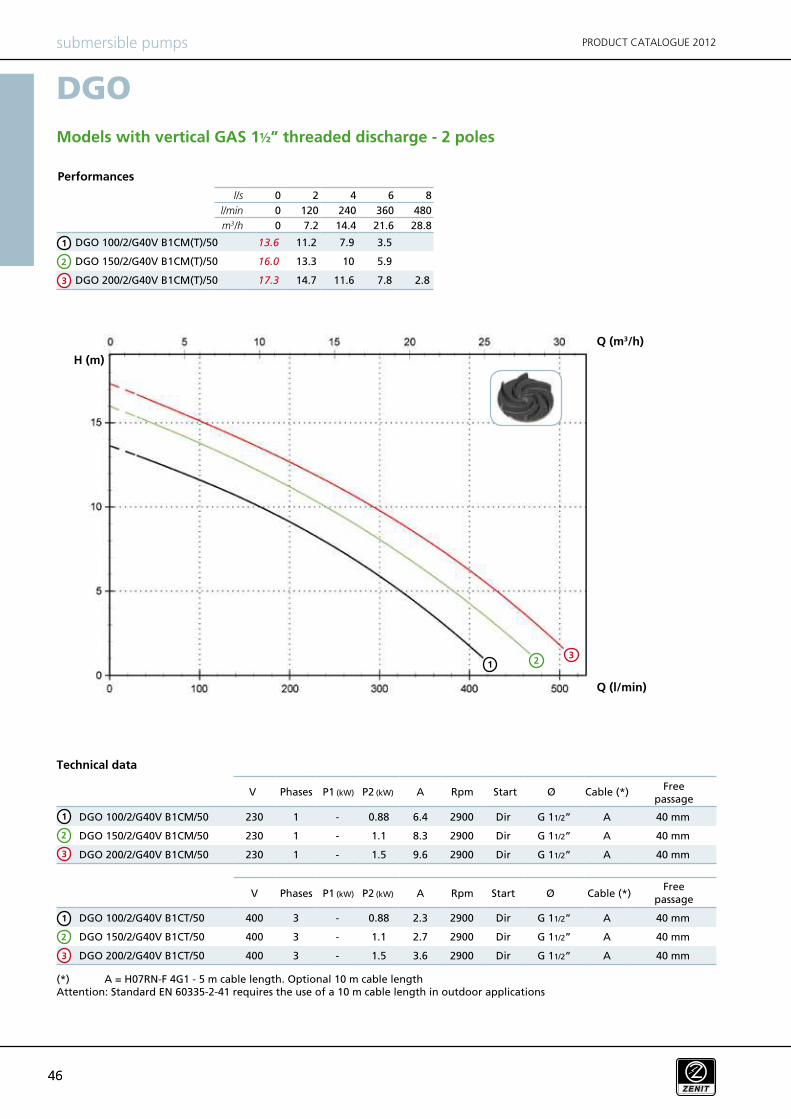
l/s 0 2 4 6 8
l/min 0 120 240 360 480
m3/h 0 7.2 14.4 21.6 28.8
DGO 100/2/G40V B1CM(T)/50 13.6 11.2 7.9 3.5
DGO 150/2/G40V B1CM(T)/50 16.0 13.3 10 5.9
DGO 200/2/G40V B1CM(T)/50 17.3 14.7 11.6 7.8 2.8
DGO 100/2/G40V B1CT/50 400 3 - 0.88 2.3 2900 Dir G 11/2” A 40 mm
DGO 150/2/G40V B1CT/50 400 3 - 1.1 2.7 2900 Dir G 11/2” A 40 mm
DGO 200/2/G40V B1CT/50 400 3 - 1.5 3.6 2900 Dir G 11/2” A 40 mm
DGO 100/2/G40V B1CM/50 230 1 - 0.88 6.4 2900 Dir G 11/2” A 40 mm
DGO 150/2/G40V B1CM/50 230 1 - 1.1 8.3 2900 Dir G 11/2” A 40 mm
DGO 200/2/G40V B1CM/50 230 1 - 1.5 9.6 2900 Dir G 11/2” A 40 mm
DGO
V A Rpm ØP1 (kW) P2 (kW) Start
V A RpmP1 (kW) P2 (kW) Start Ø
submersible pumps PRODUCT CATALOGUE 2012
Phases Cable (*)
Performances
Technical data
Models with vertical GAS 1½” threaded discharge - 2 poles
Phases Cable (*)Free
passage
(*) A = H07RN-F 4G1 - 5 m cable length. Optional 10 m cable length Attention: Standard EN 60335-2-41 requires the use of a 10 m cable length in outdoor applications
Free passage
Q (l/min)
Q (m3/h)
H (m)
213
2
1
3
2
1
3
2
1
3

47
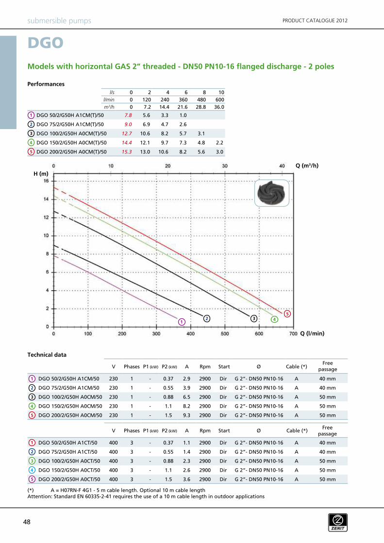
l/s 0 2 4 6 8 10
l/min 0 120 240 360 480 600
m3/h 0 7.2 14.4 21.6 28.8 36.0
DGO 50/2/G50V B0CM(T)/50 6.0 4.5 2.3
DGO 75/2/G50V B0CM(T)/50 8.6 7.2 5.1 2.3
DGO 100/2/G50V B0CM(T)/50 12.2 10.1 7.9 5.8 3.6
DGO 150/2/G50V B0CM(T)/50 14.2 11.8 9.5 7.3 5.1 2.7
DGO 200/2/G50V B0CM(T)/50 15.8 13.6 11.2 8.9 6.6 4.4
DGO 50/2/G50V B0CM/50 230 1 - 0.37 2.9 2900 Dir G 2” A 40 mm
DGO 75/2/G50V B0CM/50 230 1 - 0.55 3.9 2900 Dir G 2” A 40 mm
DGO 100/2/G50V B0CM/50 230 1 - 0.88 6.9 2900 Dir G 2” A 50 mm
DGO 150/2/G50V B0CM/50 230 1 - 1.1 8.7 2900 Dir G 2” A 50 mm
DGO 200/2/G50V B0CM/50 230 1 - 1.5 10.4 2900 Dir G 2” A 50 mm
DGO 50/2/G50V B0CT/50 400 3 - 0.37 1.1 2900 Dir G 2” A 40 mm
DGO 75/2/G50V B0CT/50 400 3 - 0.55 1.4 2900 Dir G 2” A 40 mm
DGO 100/2/G50V B0CT/50 400 3 - 0.88 2.3 2900 Dir G 2” A 50 mm
DGO 150/2/G50V B0CT/50 400 3 - 1.1 2.7 2900 Dir G 2” A 50 mm
DGO 200/2/G50V B0CT/50 400 3 - 1.5 3.6 2900 Dir G 2” A 50 mm
DGO
V P1 (kW) P2 (kW) A Rpm Ø
V A Rpm ØP1 (kW) P2 (kW)
Start
Start
submersible pumpsPRODUCT CATALOGUE 2012
Performances
Phases Cable (*)Free
passage
Technical data
Phases Cable (*)Free
passage
Models with vertical GAS 2” threaded discharge - 2 poles
(*) A = H07RN-F 4G1 - 5 m cable length. Optional 10 m cable length Attention: Standard EN 60335-2-41 requires the use of a 10 m cable length in outdoor applications
Q (l/min)
Q (m3/h)
H (m)
2
4
1
3
5
2 41 3
5
2
4
1
3
5
2
4
1
3
5
4848
l/s 0 2 4 6 8 10
l/min 0 120 240 360 480 600
m3/h 0 7.2 14.4 21.6 28.8 36.0
DGO 50/2/G50H A1CM(T)/50 7.8 5.6 3.3 1.0
DGO 75/2/G50H A1CM(T)/50 9.0 6.9 4.7 2.6
DGO 100/2/G50H A0CM(T)/50 12.7 10.6 8.2 5.7 3.1
DGO 150/2/G50H A0CM(T)/50 14.4 12.1 9.7 7.3 4.8 2.2
DGO 200/2/G50H A0CM(T)/50 15.3 13.0 10.6 8.2 5.6 3.0
DGO 50/2/G50H A1CM/50 230 1 - 0.37 2.9 2900 Dir G 2”- DN50 PN10-16 A 40 mm
DGO 75/2/G50H A1CM/50 230 1 - 0.55 3.9 2900 Dir G 2”- DN50 PN10-16 A 40 mm
DGO 100/2/G50H A0CM/50 230 1 - 0.88 6.5 2900 Dir G 2”- DN50 PN10-16 A 50 mm
DGO 150/2/G50H A0CM/50 230 1 - 1.1 8.2 2900 Dir G 2”- DN50 PN10-16 A 50 mm
DGO 200/2/G50H A0CM/50 230 1 - 1.5 9.3 2900 Dir G 2”- DN50 PN10-16 A 50 mm
DGO 50/2/G50H A1CT/50 400 3 - 0.37 1.1 2900 Dir G 2”- DN50 PN10-16 A 40 mm
DGO 75/2/G50H A1CT/50 400 3 - 0.55 1.4 2900 Dir G 2”- DN50 PN10-16 A 40 mm
DGO 100/2/G50H A0CT/50 400 3 - 0.88 2.3 2900 Dir G 2”- DN50 PN10-16 A 50 mm
DGO 150/2/G50H A0CT/50 400 3 - 1.1 2.6 2900 Dir G 2”- DN50 PN10-16 A 50 mm
DGO 200/2/G50H A0CT/50 400 3 - 1.5 3.6 2900 Dir G 2”- DN50 PN10-16 A 50 mm
DGO
V P1 (kW) P2 (kW) A Rpm Ø
V A Rpm ØP1 (kW) P2 (kW)
Start
Start
submersible pumps PRODUCT CATALOGUE 2012
Performances
Phases Cable (*)Free
passage
Technical data
Phases Cable (*)Free
passage
Models with horizontal GAS 2” threaded - DN50 PN10-16 flanged discharge - 2 poles
(*) A = H07RN-F 4G1 - 5 m cable length. Optional 10 m cable length Attention: Standard EN 60335-2-41 requires the use of a 10 m cable length in outdoor applications
2
4
1
3
5
Q (l/min)
Q (m3/h)
H (m)
2 41
35
2
4
1
3
5
2
4
1
3
5
49
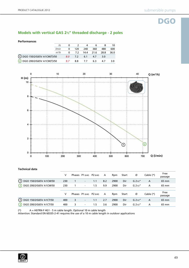
l/s 0 2 4 6 8 10
l/min 0 120 240 360 480 600
m3/h 0 7.2 14.4 21.6 28.8 36.0
DGO 150/2/G65V A1CM(T)/50 8.0 7.2 6.1 4.7 3.0
DGO 200/2/G65V A1CM(T)/50 9.7 8.8 7.7 6.3 4.7 3.0
DGO 150/2/G65V A1CM/50 230 1 - 1.1 8.2 2900 Dir G 21/2” A 65 mm
DGO 200/2/G65V A1CM/50 230 1 - 1.5 9.9 2900 Dir G 21/2” A 65 mm
DGO 150/2/G65V A1CT/50 400 3 - 1.1 2.7 2900 Dir G 21/2” A 65 mm
DGO 200/2/G65V A1CT/50 400 3 - 1.5 3.6 2900 Dir G 21/2” A 65 mm
1
2
1 2
DGO
V P1 (kW) P2 (kW) A Rpm Ø
V A Rpm ØP1 (kW) P2 (kW)
Start
Start
submersible pumpsPRODUCT CATALOGUE 2012
Performances
Phases Cable (*)Free
passage
Technical data
Phases Cable (*)Free
passage
Models with vertical GAS 2½” threaded discharge - 2 poles
(*) A = H07RN-F 4G1 - 5 m cable length. Optional 10 m cable length Attention: Standard EN 60335-2-41 requires the use of a 10 m cable length in outdoor applications
Q (l/min)
Q (m3/h)
H (m)
1
2
1
2
5050
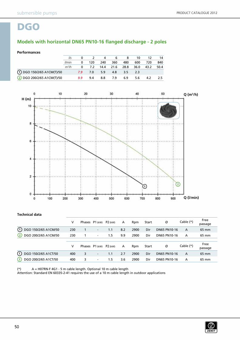
l/s 0 2 4 6 8 10 12 14
l/min 0 120 240 360 480 600 720 840
m3/h 0 7.2 14.4 21.6 28.8 36.0 43.2 50.4
DGO 150/2/65 A1CM(T)/50 7.9 7.0 5.9 4.8 3.5 2.3
DGO 200/2/65 A1CM(T)/50 9.9 9.4 8.8 7.9 6.9 5.6 4.2 2.5
DGO 150/2/65 A1CM/50 230 1 - 1.1 8.2 2900 Dir DN65 PN10-16 A 65 mm
DGO 200/2/65 A1CM/50 230 1 - 1.5 9.9 2900 Dir DN65 PN10-16 A 65 mm
DGO 150/2/65 A1CT/50 400 3 - 1.1 2.7 2900 Dir DN65 PN10-16 A 65 mm
DGO 200/2/65 A1CT/50 400 3 - 1.5 3.6 2900 Dir DN65 PN10-16 A 65 mm
DGO
V P1 (kW) P2 (kW) A Rpm Ø
V A Rpm ØP1 (kW) P2 (kW)
Start
Start
submersible pumps PRODUCT CATALOGUE 2012
Performances
Phases Cable (*)Free
passage
Technical data
Phases Cable (*)Free
passage
Models with horizontal DN65 PN10-16 flanged discharge - 2 poles
(*) A = H07RN-F 4G1 - 5 m cable length. Optional 10 m cable length Attention: Standard EN 60335-2-41 requires the use of a 10 m cable length in outdoor applications
Q (l/min)
Q (m3/h)
H (m)
12
1
2
1
2
1
2
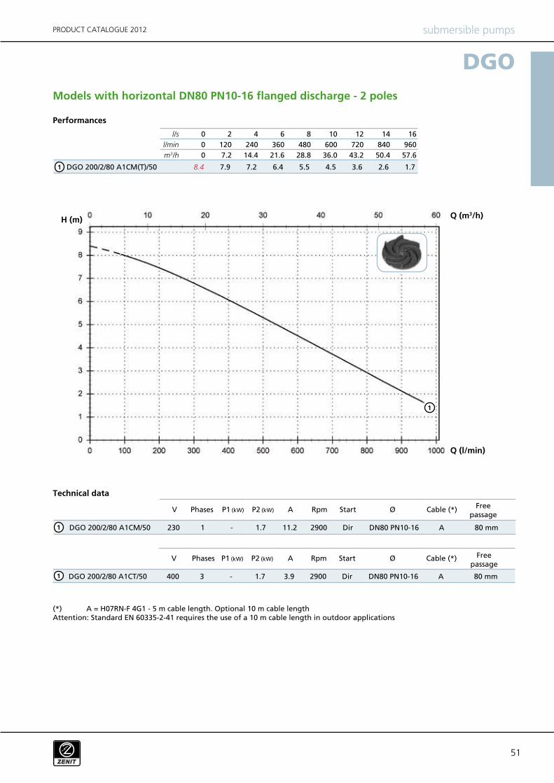
51
l/s 0 2 4 6 8 10 12 14 16
l/min 0 120 240 360 480 600 720 840 960
m3/h 0 7.2 14.4 21.6 28.8 36.0 43.2 50.4 57.6
DGO 200/2/80 A1CM(T)/50 8.4 7.9 7.2 6.4 5.5 4.5 3.6 2.6 1.7
DGO 200/2/80 A1CM/50 230 1 - 1.7 11.2 2900 Dir DN80 PN10-16 A 80 mm
DGO 200/2/80 A1CT/50 400 3 - 1.7 3.9 2900 Dir DN80 PN10-16 A 80 mm
DGO
V P1 (kW) P2 (kW) A Rpm Ø
V A Rpm ØP1 (kW) P2 (kW)
Start
Start
submersible pumpsPRODUCT CATALOGUE 2012
Performances
Phases Cable (*)Free
passage
Technical data
Phases Cable (*) Free passage
Models with horizontal DN80 PN10-16 flanged discharge - 2 poles
(*) A = H07RN-F 4G1 - 5 m cable length. Optional 10 m cable length Attention: Standard EN 60335-2-41 requires the use of a 10 m cable length in outdoor applications
1
Q (l/min)
Q (m3/h)H (m)
1
1
1
5252
DGO 100/4/G50V B0CM/50 230 1 - 0.7 4.5 1450 Dir G 2” A 45 mm
DGO 100/4/G50V B0CT/50 400 3 - 0.7 1.6 1450 Dir G 2” A 45 mm
l/s 0 1 2 3 4 5 6 7 8 9
l/min 0 60 120 180 240 300 360 420 480 540
m3/h 0 3.6 7.2 10.8 14.4 18.0 21.6 25.2 28.8 32.4
DGO 100/4/G50V B0CM(T)/50 5.4 5.1 4.8 4.4 4.0 3.5 3.0 2.4 1.8 1.1
1
1
DGO
V P1 (kW) P2 (kW) A Rpm Ø
V A Rpm ØP1 (kW) P2 (kW)
Start
Start
submersible pumps PRODUCT CATALOGUE 2012
Performances
Phases Cable (*)Free
passage
Technical data
Phases Cable (*)Free
passage
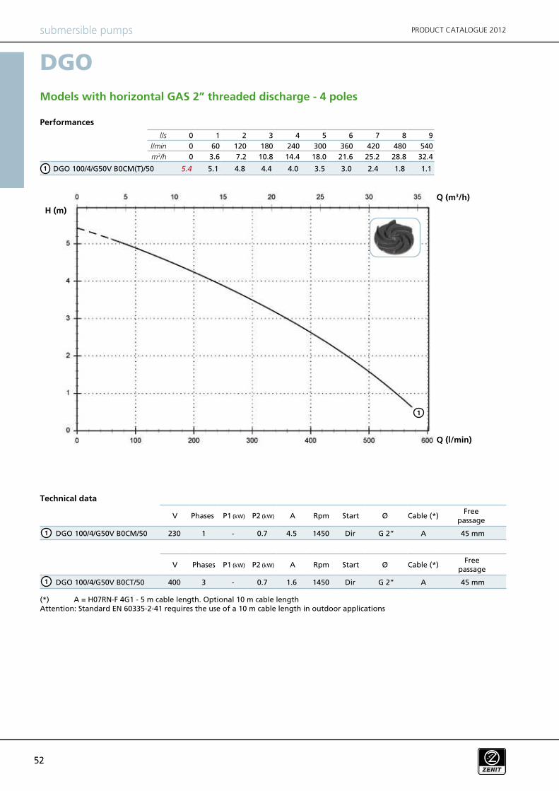
Models with horizontal GAS 2” threaded discharge - 4 poles
(*) A = H07RN-F 4G1 - 5 m cable length. Optional 10 m cable length Attention: Standard EN 60335-2-41 requires the use of a 10 m cable length in outdoor applications
Q (l/min)
Q (m3/h)
H (m)
1
1
53
l/s 0 1 2 3 4 5 6 7 8
l/min 0 60 120 180 240 300 360 420 480
m3/h 0 3.6 7.2 10.8 14.4 18 21.6 25.2 28.8
DGO 100/4/G50H A0CM(T)/50 5.2 4.9 4.7 4.4 4.1 3.8 3.3 2.7 1.6
DGO 100/4/G50H A0CM/50 230 1 - 0.7 5.7 1450 Dir G 2’’ DN50 PN10 A 45 mm
DGO 100/4/G50H A0CT/50 400 3 - 0.7 2.2 1450 Dir G 2’’ DN50 PN10 A 45 mm
DGO
Start
Start
V P1 (kW) P2 (kW) A Rpm Ø
V A Rpm ØP1 (kW) P2 (kW)
submersible pumpsPRODUCT CATALOGUE 2012
Performances
Phases Cable (*)
Technical data
Phases Cable (*)
(*) A = H07RN-F 4G1 - 5 m cable length. Optional 10 m cable length Attention: Standard EN 60335-2-41 requires the use of a 10 m cable length in outdoor applications
Freepassage
Freepassage
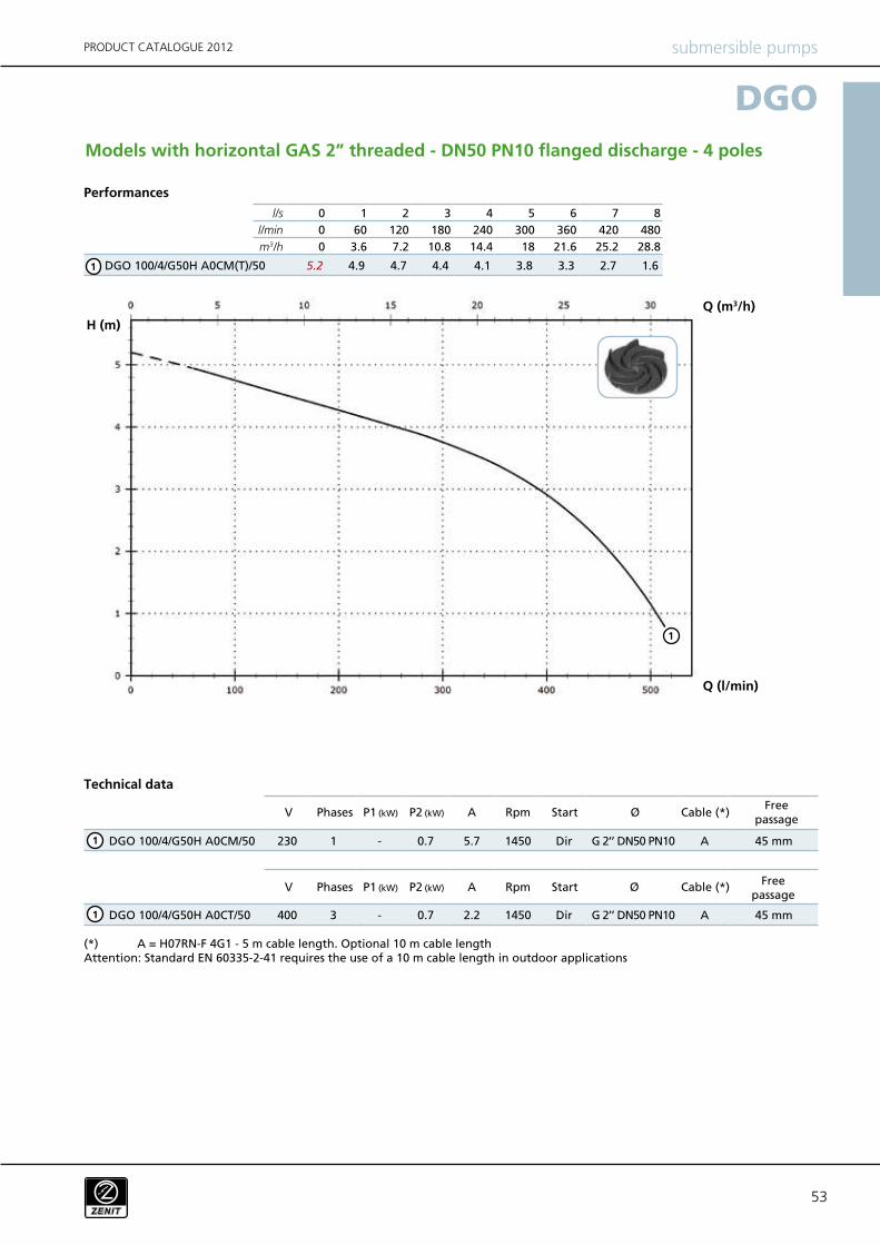
Models with horizontal GAS 2” threaded - DN50 PN10 flanged discharge - 4 poles
1
1
1
Q (l/min)
Q (m3/h)
H (m)
1
5454
l/s 0 2 4 6 8 10 12
l/min 0 120 240 360 480 600 720
m3/h 0 7.2 14.4 21.6 28.8 36.0 43.2
DGO 150/4/65 A0CM(T)/50 5.9 5.5 5.1 4.6 3.9 3.0 1.9
DGO 150/4/65 A0CM/50 230 1 - 0.9 7.5 1450 Dir DN65 PN10-16 A 45 mm
DGO 150/4/65 A0CT/50 400 3 - 0.9 2.8 1450 Dir DN65 PN10-16 A 45 mm
DGO
Start
Start
V P1 (kW) P2 (kW) A Rpm Ø
V A Rpm ØP1 (kW) P2 (kW)
submersible pumps PRODUCT CATALOGUE 2012
Performances
Phases Cable (*)
Technical data
Phases Cable (*)
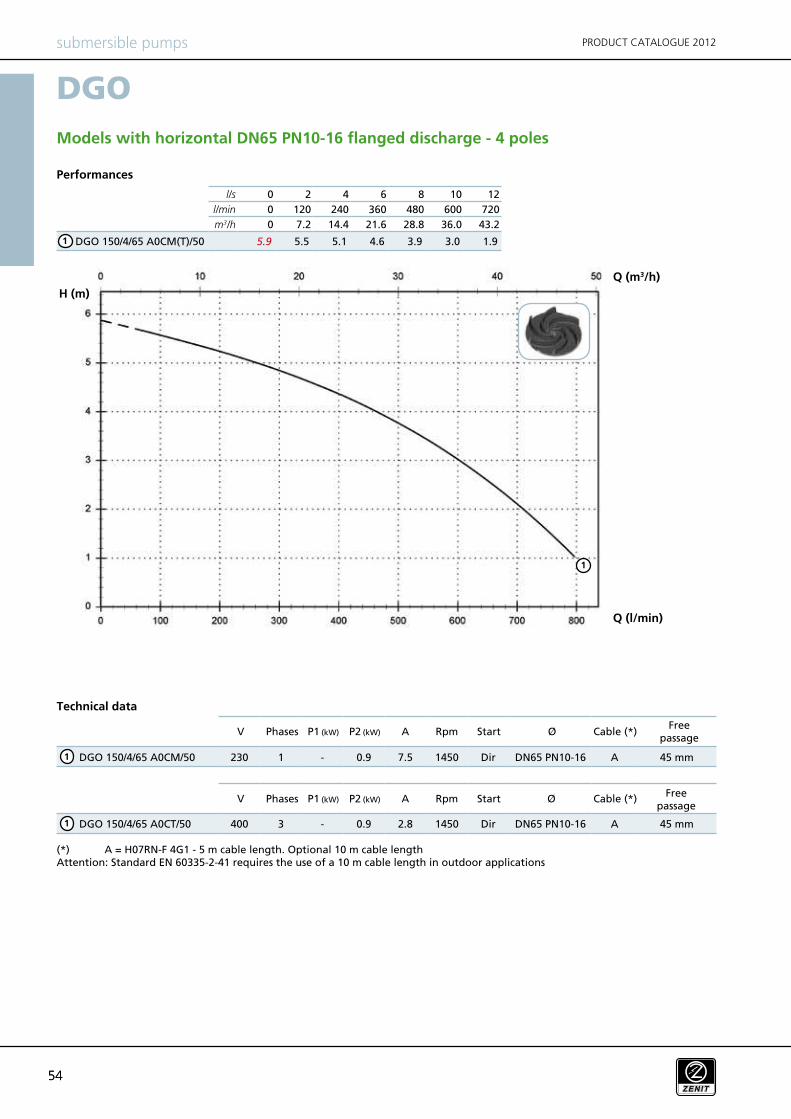
Models with horizontal DN65 PN10-16 flanged discharge - 4 poles
(*) A = H07RN-F 4G1 - 5 m cable length. Optional 10 m cable length Attention: Standard EN 60335-2-41 requires the use of a 10 m cable length in outdoor applications
Freepassage
Freepassage
1
1
1
Q (l/min)
Q (m3/h)
H (m)
1
55
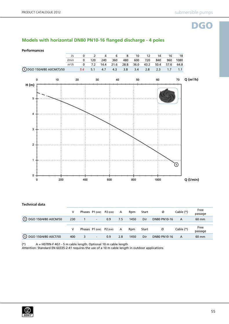
l/s 0 2 4 6 8 10 12 14 16 18
l/min 0 120 240 360 480 600 720 840 960 1080
m3/h 0 7.2 14.4 21.6 28.8 36.0 43.2 50.4 57.6 64.8
DGO 150/4/80 A0CM(T)/50 5.4 5.1 4.7 4.3 3.8 3.4 2.8 2.3 1.7 1.1
DGO 150/4/80 A0CM/50 230 1 - 0.9 7.5 1450 Dir DN80 PN10-16 A 60 mm
DGO 150/4/80 A0CT/50 400 3 - 0.9 2.8 1450 Dir DN80 PN10-16 A 60 mm
DGO
V P1 (kW) P2 (kW) A Rpm Ø
V A Rpm ØP1 (kW) P2 (kW)
Start
Start
submersible pumpsPRODUCT CATALOGUE 2012
Performances
Phases Cable (*)Free
passage
Technical data
Phases Cable (*)Free
passage
Models with horizontal DN80 PN10-16 flanged discharge - 4 poles
(*) A = H07RN-F 4G1 - 5 m cable length. Optional 10 m cable length Attention: Standard EN 60335-2-41 requires the use of a 10 m cable length in outdoor applications
Q (l/min)
Q (m3/h)
H (m)
1
1
1
1
5656
NAE T
TC
TCD
TCDT
TCDGT
TCG
TCST
TCSGT
TS
TR
TRG
NCCCCE
FTCGFT
2SIC SICM SICAL 2SICAL
DGO 100/2/G40V B1CM/50
DGO 150/2/G40V B1CM/50
DGO 200/2/G40V B1CM/50
DGO 100/2/G40V B1CT/50
DGO 150/2/G40V B1CT/50
DGO 200/2/G40V B1CT/50
DGO 50/2/G50V B0CM/50
DGO 75/2/G50V B0CM/50
DGO 100/2/G50V B0CM/50
DGO 150/2/G50V B0CM/50
DGO 200/2/G50V B0CM/50
DGO 50/2/G50V B0CT/50
DGO 75/2/G50V B0CT/50
DGO 100/2/G50V B0CT/50
DGO 150/2/G50V B0CT/50
DGO 200/2/G50V B0CT/50
DGO 50/2/G50H A1CM/50
DGO 75/2/G50H A1CM/50
DGO 100/2/G50H A0CM/50
DGO 150/2/G50H A0CM/50
DGO 200/2/G50H A0CM/50
DGO 50/2/G50H A1CT/50
DGO 75/2/G50H A1CT/50
DGO 100/2/G50H A0CT/50
DGO 150/2/G50H A0CT/50
DGO 200/2/G50H A0CT/50
DGO 150/2/G65V A1CM/50
DGO 200/2/G65V A1CM/50
DGO 150/2/G65V A1CT/50
DGO 200/2/G65V A1CT/50
DGO 150/2/65 A1CM/50
DGO 200/2/65 A1CM/50
DGO 150/2/65 A1CT/50
DGO 200/2/65 A1CT/50
DGO 200/2/80 A1CM/50
DGO 200/2/80 A1CT/50
DGO 100/4/G50V B0CM/50
DGO 100/4/G50V B0CT/50
DGO 100/4/G50H A0CM/50
DGO 100/4/G50H A0CT/50
DGO 150/4/65 A0CM/50
DGO 150/4/65 A0CT/50
DGO 150/4/80 A0CM/50
DGO 150/4/80 A0CT/50
DGO
submersible pumps PRODUCT CATALOGUE 2012
Versions available
(Key to versions on page 16)
Mechanical sealsElectrical variants Cooling
57
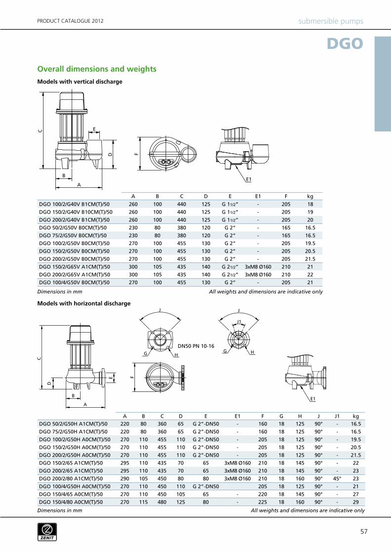
A B C D E E1 F kg
DGO 100/2/G40V B1CM(T)/50 260 100 440 125 G 11/2” - 205 18
DGO 150/2/G40V B10CM(T)/50 260 100 440 125 G 11/2” - 205 19
DGO 200/2/G40V B1CM(T)/50 260 100 440 125 G 11/2” - 205 20
DGO 50/2/G50V B0CM(T)/50 230 80 380 120 G 2” - 165 16.5
DGO 75/2/G50V B0CM(T)/50 230 80 380 120 G 2” - 165 16.5
DGO 100/2/G50V B0CM(T)/50 270 100 455 130 G 2” - 205 19.5
DGO 150/2/G50V B0CM(T)/50 270 100 455 130 G 2” - 205 20.5
DGO 200/2/G50V B0CM(T)/50 270 100 455 130 G 2” - 205 21.5
DGO 150/2/G65V A1CM(T)/50 300 105 435 140 G 21/2” 3xM8 Ø160 210 21
DGO 200/2/G65V A1CM(T)/50 300 105 435 140 G 21/2” 3xM8 Ø160 210 22
DGO 100/4/G50V B0CM(T)/50 270 100 455 130 G 2” - 205 21
A B C D E E1 F G H J J1 kg
DGO 50/2/G50H A1CM(T)/50 220 80 360 65 G 2”-DN50 - 160 18 125 90° - 16.5
DGO 75/2/G50H A1CM(T)/50 220 80 360 65 G 2”-DN50 - 160 18 125 90° - 16.5
DGO 100/2/G50H A0CM(T)/50 270 110 455 110 G 2”-DN50 - 205 18 125 90° - 19.5
DGO 150/2/G50H A0CM(T)/50 270 110 455 110 G 2”-DN50 - 205 18 125 90° - 20.5
DGO 200/2/G50H A0CM(T)/50 270 110 455 110 G 2”-DN50 - 205 18 125 90° - 21.5
DGO 150/2/65 A1CM(T)/50 295 110 435 70 65 3xM8 Ø160 210 18 145 90° - 22
DGO 200/2/65 A1CM(T)/50 295 110 435 70 65 3xM8 Ø160 210 18 145 90° - 23
DGO 200/2/80 A1CM(T)/50 290 105 450 80 80 3xM8 Ø160 210 18 160 90° 45° 23
DGO 100/4/G50H A0CM(T)/50 270 110 450 110 G 2”-DN50 205 18 125 90° - 21
DGO 150/4/65 A0CM(T)/50 270 110 450 105 65 - 220 18 145 90° - 27
DGO 150/4/80 A0CM(T)/50 270 115 480 125 80 - 225 18 160 90° - 29
DGO
DN50 PN 10-16
submersible pumpsPRODUCT CATALOGUE 2012
Overall dimensions and weights
Models with vertical discharge
Models with horizontal discharge
Dimensions in mm
Dimensions in mm
All weights and dimensions are indicative only
All weights and dimensions are indicative only
5858
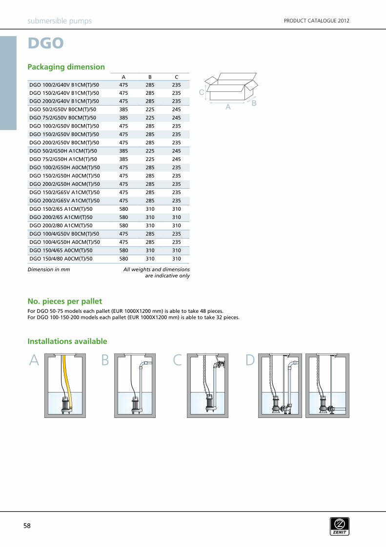
A B C
DGO 100/2/G40V B1CM(T)/50 475 285 235
DGO 150/2/G40V B1CM(T)/50 475 285 235
DGO 200/2/G40V B1CM(T)/50 475 285 235
DGO 50/2/G50V B0CM(T)/50 385 225 245
DGO 75/2/G50V B0CM(T)/50 385 225 245
DGO 100/2/G50V B0CM(T)/50 475 285 235
DGO 150/2/G50V B0CM(T)/50 475 285 235
DGO 200/2/G50V B0CM(T)/50 475 285 235
DGO 50/2/G50H A1CM(T)/50 385 225 245
DGO 75/2/G50H A1CM(T)/50 385 225 245
DGO 100/2/G50H A0CM(T)/50 475 285 235
DGO 150/2/G50H A0CM(T)/50 475 285 235
DGO 200/2/G50H A0CM(T)/50 475 285 235
DGO 150/2/G65V A1CM(T)/50 475 285 235
DGO 200/2/G65V A1CM(T)/50 475 285 235
DGO 150/2/65 A1CM(T)/50 580 310 310
DGO 200/2/65 A1CM/(T)50 580 310 310
DGO 200/2/80 A1CM(T)/50 580 310 310
DGO 100/4/G50V B0CM(T)/50 475 285 235
DGO 100/4/G50H A0CM(T)/50 475 285 235
DGO 150/4/65 A0CM(T)/50 580 310 310
DGO 150/4/80 A0CM(T)/50 580 310 310
DGO
A B DC
submersible pumps PRODUCT CATALOGUE 2012
Dimension in mm
No. pieces per pallet
Installations available
For DGO 50-75 models each pallet (EUR 1000X1200 mm) is able to take 48 pieces.For DGO 100-150-200 models each pallet (EUR 1000X1200 mm) is able to take 32 pieces.
Packaging dimension
All weights and dimensions are indicative only