

PRODUCT CATALOG writtenalloverthem. - · PDF...
63
BECAUSE YOUR BUSINESS RUNS THROUGH US BERK-TEK PRODUCT CATALOG BERK-TEK PRODUCT CATALOG The world’s highest performing network cables have Berk-Tek written all over them.
Transcript of PRODUCT CATALOG writtenalloverthem. - · PDF...
B E C A U S E Y O U R B U S I N E S S R U N S T H R O U G H U S
BERK-TEK PRODUCT CATALOG
BER
K-TEK
PRO
DU
CTCATA
LOG
Corporate Headquarters132 White Oak RoadNew Holland, PA 17557USATEL: 717-354-6200TEL: 800-237-5835FAX: 717-354-7944www.berktek.com
In Canada, please contact:Nexans Canada Inc.140 Allstate ParkwayMarkham, OntarioL3R 0Z7 CanadaTEL: 905-944-4300TEL: 800-237-5835FAX: 905-944-4390www.berktek.com
BTPRDCTCTLG 01/11 This catalog has been printed using acid-free and elemental chlorine-free paper and contains 50% recycled content, including 15% post consumer waste.
The world’s highest performing network cables have Berk-Tek written all over them.
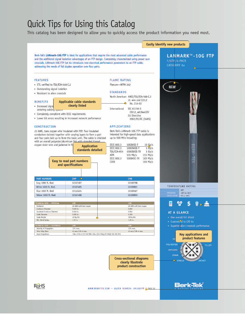
Quick Tips for Using this CatalogThis catalog has been designed to allow you to quickly access the product information you need most.
Easily identify new products
Applicable cable standardsclearly listed
Applicationstandards detailed
Easy to read part numbersand specifications
Cross-sectional diagramsclearly illustrate
product construction
Key applications andproduct features
Need to locatea distributor, getin touch withthe Berk-TekManufacturer’s Repfor your area, orjust want to learnmore about usingUTP for CCTV?
The Berk-Tek Website featurescomplete productspecifications,technical white papers, articles, installationguidelines, bid specifications and more. Visitwww.berktek.com for all your cabling productinformational needs.
www.berktek.com
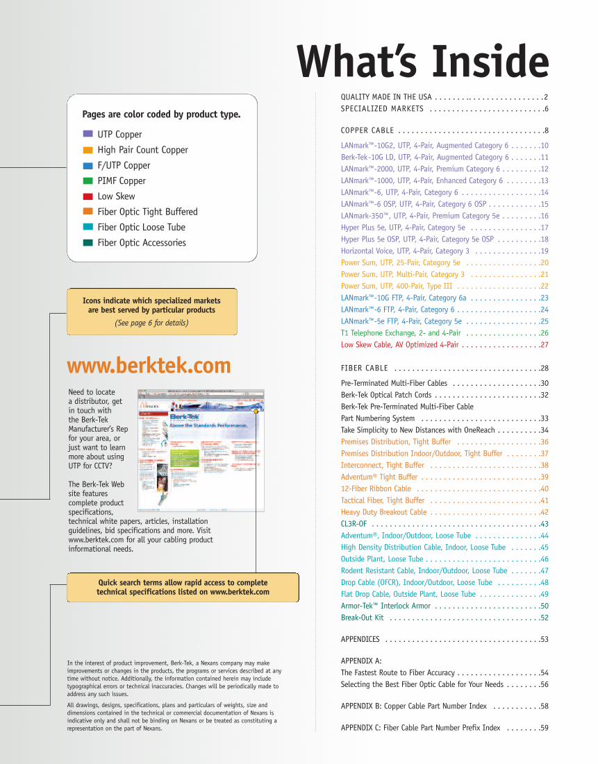
QUALITY MADE IN THE USA . . . . . . . .. . . . . . . . . . . . . . . . .2SPECIALIZED MARKETS . . . . . . . . . . . . . . . . . . . . . . . . . .6
COPPER CABLE . . . . . . . . . . . . . . . . . . . . . . . . . . . . . . . . .8
LANmark™-10G2, UTP, 4-Pair, Augmented Category 6 . . . . . . .10Berk-Tek-10G LD, UTP, 4-Pair, Augmented Category 6 . . . . . . .11LANmark™-2000, UTP, 4-Pair, Premium Category 6 . . . . . . . . .12LANmark™-1000, UTP, 4-Pair, Enhanced Category 6 . . . . . . . .13LANmark™-6, UTP, 4-Pair, Category 6 . . . . . . . . . . . . . . . . . .14LANmark™-6 OSP, UTP, 4-Pair, Category 6 OSP . . . . . . . . . . . .15LANmark-350™, UTP, 4-Pair, Premium Category 5e . . . . . . . . .16Hyper Plus 5e, UTP, 4-Pair, Category 5e . . . . . . . . . . . . . . . .17Hyper Plus 5e OSP, UTP, 4-Pair, Category 5e OSP . . . . . . . . . .18Horizontal Voice, UTP, 4-Pair, Category 3 . . . . . . . . . . . . . . .19Power Sum, UTP, 25-Pair, Category 5e . . . . . . . . . . . . . . . . .20Power Sum, UTP, Multi-Pair, Category 3 . . . . . . . . . . . . . . . .21Power Sum, UTP, 400-Pair, Type III . . . . . . . . . . . . . . . . . . .22LANmark™-10G FTP, 4-Pair, Category 6a . . . . . . . . . . . . . . . .23LANmark™-6 FTP, 4-Pair, Category 6 . . . . . . . . . . . . . . . . . . .24LANmark™-5e FTP, 4-Pair, Category 5e . . . . . . . . . . . . . . . . .25T1 Telephone Exchange, 2- and 4-Pair . . . . . . . . . . . . . . . . .26Low Skew Cable, AV Optimized 4-Pair . . . . . . . . . . . . . . . . . .27
FIBER CABLE . . . . . . . . . . . . . . . . . . . . . . . . . . . . . . . . .28
Pre-Terminated Multi-Fiber Cables . . . . . . . . . . . . . . . . . . . .30Berk-Tek Optical Patch Cords . . . . . . . . . . . . . . . . . . . . . . . .32Berk-Tek Pre-Terminated Multi-Fiber CablePart Numbering System . . . . . . . . . . . . . . . . . . . . . . . . . . .33Take Simplicity to New Distances with OneReach . . . . . . . . . .34Premises Distribution, Tight Buffer . . . . . . . . . . . . . . . . . . .36Premises Distribution Indoor/Outdoor, Tight Buffer . . . . . . . .37Interconnect, Tight Buffer . . . . . . . . . . . . . . . . . . . . . . . . .38Adventum® Tight Buffer . . . . . . . . . . . . . . . . . . . . . . . . . . .3912-Fiber Ribbon Cable . . . . . . . . . . . . . . . . . . . . . . . . . . . .40Tactical Fiber, Tight Buffer . . . . . . . . . . . . . . . . . . . . . . . . .41Heavy Duty Breakout Cable . . . . . . . . . . . . . . . . . . . . . . . . .42CL3R-OF . . . . . . . . . . . . . . . . . . . . . . . . . . . . . . . . . . . . . .43Adventum®, Indoor/Outdoor, Loose Tube . . . . . . . . . . . . . . .44High Density Distribution Cable, Indoor, Loose Tube . . . . . . .45Outside Plant, Loose Tube . . . . . . . . . . . . . . . . . . . . . . . . . .46Rodent Resistant Cable, Indoor/Outdoor, Loose Tube . . . . . . .47Drop Cable (OFCR), Indoor/Outdoor, Loose Tube . . . . . . . . . .48Flat Drop Cable, Outside Plant, Loose Tube . . . . . . . . . . . . . .49Armor-Tek™ Interlock Armor . . . . . . . . . . . . . . . . . . . . . . . .50Break-Out Kit . . . . . . . . . . . . . . . . . . . . . . . . . . . . . . . . . .52
APPENDICES . . . . . . . . . . . . . . . . . . . . . . . . . . . . . . . . . . .53
APPENDIX A:The Fastest Route to Fiber Accuracy . . . . . . . . . . . . . . . . . . .54Selecting the Best Fiber Optic Cable for Your Needs . . . . . . . .56
APPENDIX B: Copper Cable Part Number Index . . . . . . . . . . .58
APPENDIX C: Fiber Cable Part Number Prefix Index . . . . . . . .59
What’s InsidePages are color coded by product type.
UTP Copper
High Pair Count Copper
F/UTP Copper
PIMF Copper
Low Skew
Fiber Optic Tight Buffered
Fiber Optic Loose Tube
Fiber Optic Accessories
Icons indicate which specialized marketsare best served by particular products
(See page 6 for details)
Quick search terms allow rapid access to completetechnical specifications listed on www.berktek.com
In the interest of product improvement, Berk-Tek, a Nexans company may makeimprovements or changes in the products, the programs or services described at anytime without notice. Additionally, the information contained herein may includetypographical errors or technical inaccuracies. Changes will be periodically made toaddress any such issues.
All drawings, designs, specifications, plans and particulars of weights, size anddimensions contained in the technical or commercial documentation of Nexans isindicative only and shall not be binding on Nexans or be treated as constituting arepresentation on the part of Nexans.
PAGE | WWW.B ERK T E K . C OM2
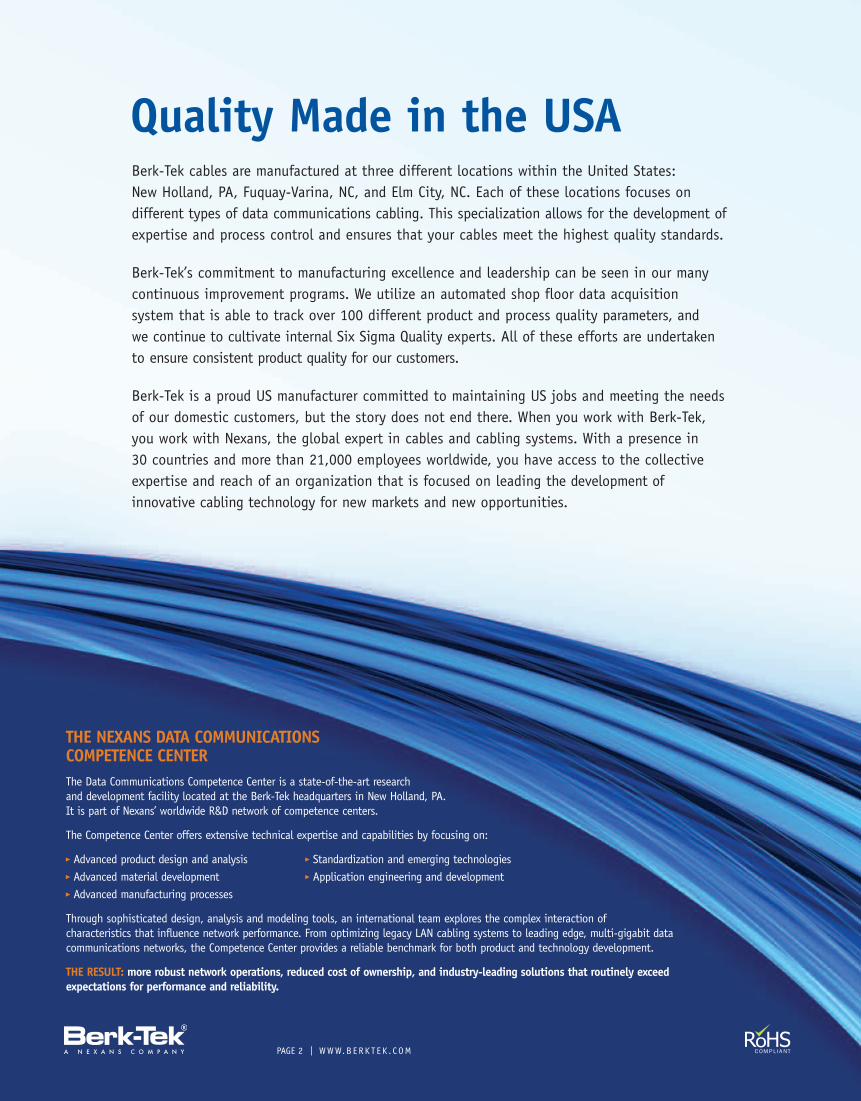
THE NEXANS DATA COMMUNICATIONSCOMPETENCE CENTERThe Data Communications Competence Center is a state-of-the-art researchand development facility located at the Berk-Tek headquarters in New Holland, PA.It is part of Nexans’ worldwide R&D network of competence centers.
The Competence Center offers extensive technical expertise and capabilities by focusing on:
� Advanced product design and analysis � Standardization and emerging technologies� Advanced material development � Application engineering and development� Advanced manufacturing processes
Through sophisticated design, analysis and modeling tools, an international team explores the complex interaction ofcharacteristics that influence network performance. From optimizing legacy LAN cabling systems to leading edge, multi-gigabit datacommunications networks, the Competence Center provides a reliable benchmark for both product and technology development.
THE RESULT: more robust network operations, reduced cost of ownership, and industry-leading solutions that routinely exceedexpectations for performance and reliability.
Quality Made in the USABerk-Tek cables are manufactured at three different locations within the United States:New Holland, PA, Fuquay-Varina, NC, and Elm City, NC. Each of these locations focuses ondifferent types of data communications cabling. This specialization allows for the development ofexpertise and process control and ensures that your cables meet the highest quality standards.
Berk-Tek’s commitment to manufacturing excellence and leadership can be seen in our manycontinuous improvement programs. We utilize an automated shop floor data acquisitionsystem that is able to track over 100 different product and process quality parameters, andwe continue to cultivate internal Six Sigma Quality experts. All of these efforts are undertakento ensure consistent product quality for our customers.
Berk-Tek is a proud US manufacturer committed to maintaining US jobs and meeting the needsof our domestic customers, but the story does not end there. When you work with Berk-Tek,you work with Nexans, the global expert in cables and cabling systems. With a presence in30 countries and more than 21,000 employees worldwide, you have access to the collectiveexpertise and reach of an organization that is focused on leading the development ofinnovative cabling technology for new markets and new opportunities.
OUTS TAND ING PRODUC T P E R FORMANC E
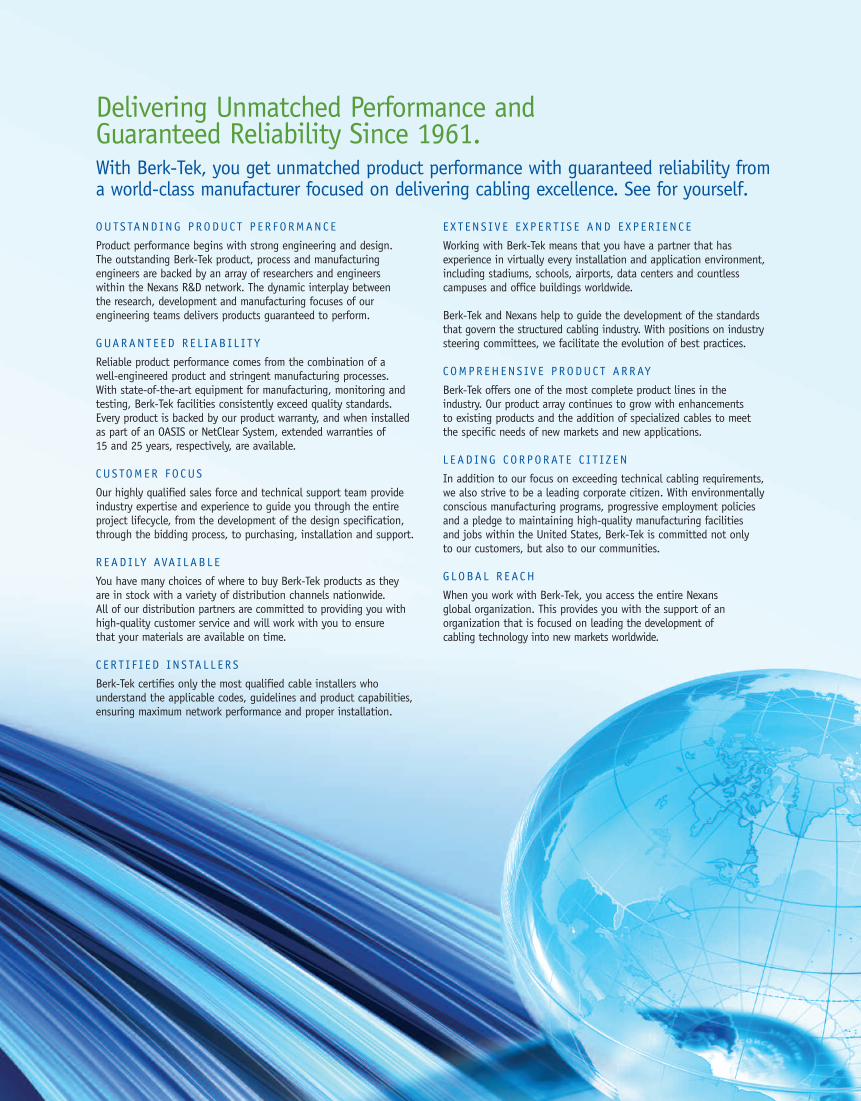
Product performance begins with strong engineering and design.The outstanding Berk-Tek product, process and manufacturingengineers are backed by an array of researchers and engineerswithin the Nexans R&D network. The dynamic interplay betweenthe research, development and manufacturing focuses of ourengineering teams delivers products guaranteed to perform.
GUARANT E ED R E L I AB I L I T Y
Reliable product performance comes from the combination of awell-engineered product and stringent manufacturing processes.With state-of-the-art equipment for manufacturing, monitoring andtesting, Berk-Tek facilities consistently exceed quality standards.Every product is backed by our product warranty, and when installedas part of an OASIS or NetClear System, extended warranties of15 and 25 years, respectively, are available.
CUS TOMER FO CUS
Our highly qualified sales force and technical support team provideindustry expertise and experience to guide you through the entireproject lifecycle, from the development of the design specification,through the bidding process, to purchasing, installation and support.
R EAD I LY AVA I LAB L E
You have many choices of where to buy Berk-Tek products as theyare in stock with a variety of distribution channels nationwide.All of our distribution partners are committed to providing you withhigh-quality customer service and will work with you to ensurethat your materials are available on time.
C E R T I F I E D IN S TA L L E R S
Berk-Tek certifies only the most qualified cable installers whounderstand the applicable codes, guidelines and product capabilities,ensuring maximum network performance and proper installation.
E X T EN S I V E E X P E R T IS E AND E X P E R I EN C E
Working with Berk-Tek means that you have a partner that hasexperience in virtually every installation and application environment,including stadiums, schools, airports, data centers and countlesscampuses and office buildings worldwide.
Berk-Tek and Nexans help to guide the development of the standardsthat govern the structured cabling industry. With positions on industrysteering committees, we facilitate the evolution of best practices.
C OMPR EHENS I V E PRODUC T ARRAY
Berk-Tek offers one of the most complete product lines in theindustry. Our product array continues to grow with enhancementsto existing products and the addition of specialized cables to meetthe specific needs of new markets and new applications.
L E AD ING CORPORAT E C I T I Z EN
In addition to our focus on exceeding technical cabling requirements,we also strive to be a leading corporate citizen. With environmentallyconscious manufacturing programs, progressive employment policiesand a pledge to maintaining high-quality manufacturing facilitiesand jobs within the United States, Berk-Tek is committed not onlyto our customers, but also to our communities.
G L OBA L R EACH
When you work with Berk-Tek, you access the entire Nexansglobal organization. This provides you with the support of anorganization that is focused on leading the development ofcabling technology into new markets worldwide.
Delivering Unmatched Performance andGuaranteed Reliability Since 1961.With Berk-Tek, you get unmatched product performance with guaranteed reliability froma world-class manufacturer focused on delivering cabling excellence. See for yourself.

PAGE | WWW.B ERK T E K . C OM4
WORKING FOR A GREENER FUTURE.
Berk-Tek, a leader in the evolution of cabling technology, is working to be a leader in ecological responsibility.A greater understanding and appreciation of the impact of manufacturing processes and product components onthe environment has prompted Berk-Tek to control and ameliorate our impact with both process improvementsand internal greening programs. As a result, Berk-Tek continues to earn the EHP (Environment Highly Protected)label, the highest environmental rating per the ISO 14.001 standards. From innovative materials development,through positive manufacturing practices and on to standards bodies contributions, Berk-Tek truly does workto steward the planet.
ROHS
All products in this catalog manufactured in New Holland, PA,Elm City, NC, and in Fuquay-Varina, NC, meet the European Union’sRestriction of Hazardous Substances (RoHS) requirements. Thisstandard requires that products be free of lead and various otherheavy metal compounds that have been shown to be detrimentalto both people and the environment. By being RoHS compliant,Berk-Tek products are also compliant with California’s Proposition59, another leading piece of environmental legislation focused onimproving the natural environment and safeguarding human life.
R E C Y C L I NG
In an ideal world, no Berk-Tek scrap cable would be found in anylandfills. And while that isn’t the case today, we can say that weare working hard to eliminate contributions to landfills from ourmanufacturing facilities. Our scrap cable jacketing is reprocessedfor use in other products, while our reusable copper can go backinto cables or be reprocessed for other uses. In 2006, over 18 tonsof copper, aluminum, and plastic were recovered. Wheneverpossible we have transitioned from wooden reels to plastic reels
that are made from 100% recycled materials and are themselvesrecyclable. Additionally, Berk-Tek has instituted an internalrecycling program for all office paper and cardboard. And wecontinue to research new environmentally friendly materials forour products.
R AW WAT ER
Berk-Tek uses an evaporation system to handle the water usedthroughout the manufacturing process. All sanitary water is treatedon-site and meets strict EPA standards before being released intothe environment. This prevents approximately 200,000 gallons ofcontaminated water from entering our local rivers and lakes.
E N E RG Y E F F I C I EN T L IGH T ING
Energy efficient lighting for manufacturing facilities and officeshas enabled Berk-Tek to reduce our total energy demand by 10%.Installing this technology has significantly reduced the amount ofcarbon dioxide released into the environment — equal to saving367 acres of forest or removing 233 cars from the road each year.
WWW.B ERK T E K . C OM | PAGE 5
WARRANTIES
NetClear, a technology alliance between Berk-Tek andLegrand | Ortronics, provides technically advanced,co-engineered structured cabling systems with a comprehensive25-year warranty with guaranteed performance abovethe standard. The NetClear alliance is the strongest andlongest-lasting partnership in the industry today.
NetClear structured cabling systems include a complete portfolio of copper and optical fiber solutions that featureindustry leading performance for every application and environment. Every component of a NetClear solutionhas been co-engineered by the cable experts at Berk-Tek and the connectivity experts at Legrand | Ortronics toensure optimal installed channel performance. From standard voice networks, including Voice over IP, to the latest40/100 Gb/s high-speed data systems and innovative data center solutions, there is a NetClear solution designedto provide unparalleled reliability.
With the NetClear structured cabling systems, Berk-Tek and Legrand | Ortronics deliver reliability for the datacenter, enterprise LAN, financial, education, healthcare and many other environments.
Delivering Reliabilitywith Co-engineered Solutions.
The Advantage of anOpen Architecture Approach.Fully leveraging high-speed network applications in the enterpriserequires a structured cabling system that exceeds current andemerging standards, end-to-end. To achieve optimal networkperformance, every component in the system must be fullycompatible, perfectly matched and expertly installed. The Berk-TekOpen Architecture Systems Interconnection Solutions (OASIS) programis powerful enough to deliver guaranteed performance over a full 15years, yet flexible enough to utilize your preference for connectivity with Hubbell Premise Wiring, Leviton,Legrand | Ortronics or Siemon. All OASIS connectivity partners are carefully selected and qualified.
OA S IS : GUARANT E ED TOTA L SY S T EM P ER FORMANC E
The Berk-Tek OASIS program is designed specifically to address component compatibility and installationvariables in the structured cabling system and deliver guaranteed total system performance. At its core, OASISutilizes Berk-Tek's premier LANmark™ series of UTP cables and our premium fiber optic technology in concertwith connectivity provided by the industry’s leading vendors. Every OASIS solution is carefully matched andqualified through extensive research and testing, providing guaranteed total channel performance andunmatched flexibility.
PAGE | WWW.B ERK T E K . C OM6
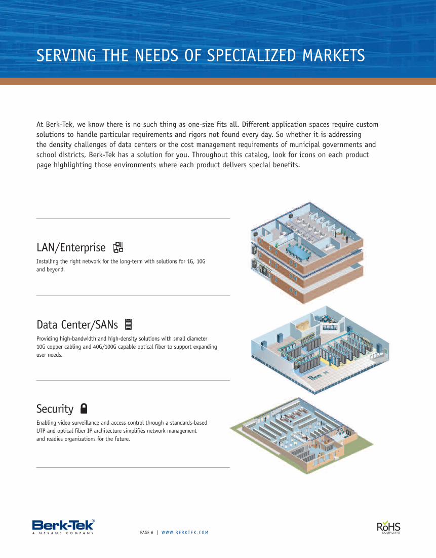
LAN/EnterpriseInstalling the right network for the long-term with solutions for 1G, 10Gand beyond.
Data Center/SANsProviding high-bandwidth and high-density solutions with small diameter10G copper cabling and 40G/100G capable optical fiber to support expandinguser needs.
SERVING THE NEEDS OF SPECIALIZED MARKETS
SecurityEnabling video surveillance and access control through a standards-basedUTP and optical fiber IP architecture simplifies network managementand readies organizations for the future.
At Berk-Tek, we know there is no such thing as one-size fits all. Different application spaces require customsolutions to handle particular requirements and rigors not found every day. So whether it is addressingthe density challenges of data centers or the cost management requirements of municipal governments andschool districts, Berk-Tek has a solution for you. Throughout this catalog, look for icons on each productpage highlighting those environments where each product delivers special benefits.
WWW.B ERK T E K . C OM | PAGE 7
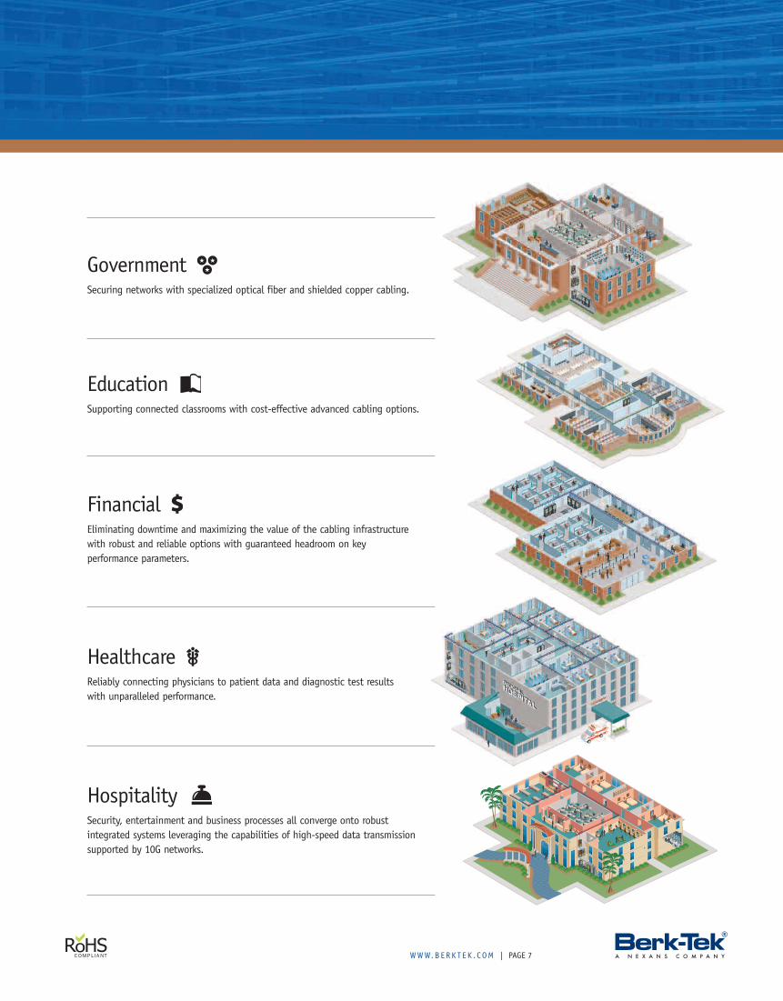
GovernmentSecuring networks with specialized optical fiber and shielded copper cabling.
EducationSupporting connected classrooms with cost-effective advanced cabling options.
FinancialEliminating downtime and maximizing the value of the cabling infrastructurewith robust and reliable options with guaranteed headroom on keyperformance parameters.
HospitalitySecurity, entertainment and business processes all converge onto robustintegrated systems leveraging the capabilities of high-speed data transmissionsupported by 10G networks.
HealthcareReliably connecting physicians to patient data and diagnostic test resultswith unparalleled performance.
PAGE | WWW.B ERK T E K . C OM8
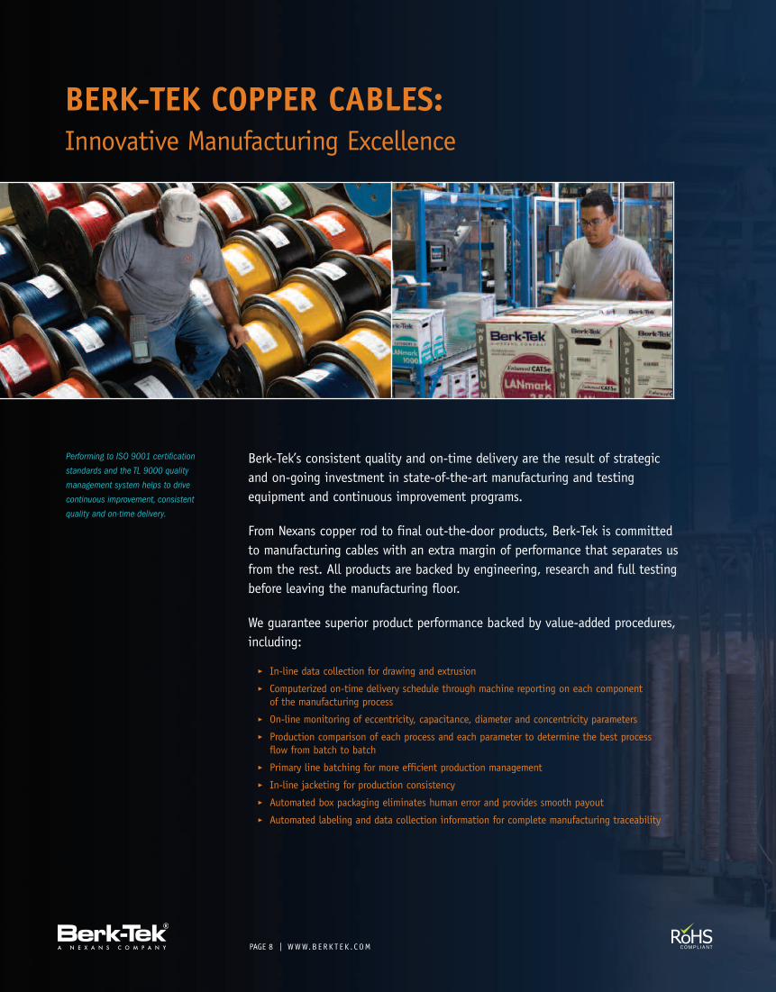
BERK-TEK COPPER CABLES:Innovative Manufacturing Excellence
Performing to ISO 9001 certification
standards and the TL 9000 quality
management system helps to drive
continuous improvement, consistent
quality and on-time delivery.
Berk-Tek’s consistent quality and on-time delivery are the result of strategicand on-going investment in state-of-the-art manufacturing and testingequipment and continuous improvement programs.
From Nexans copper rod to final out-the-door products, Berk-Tek is committedto manufacturing cables with an extra margin of performance that separates usfrom the rest. All products are backed by engineering, research and full testingbefore leaving the manufacturing floor.
We guarantee superior product performance backed by value-added procedures,including:
� In-line data collection for drawing and extrusion� Computerized on-time delivery schedule through machine reporting on each componentof the manufacturing process
� On-line monitoring of eccentricity, capacitance, diameter and concentricity parameters� Production comparison of each process and each parameter to determine the best processflow from batch to batch
� Primary line batching for more efficient production management� In-line jacketing for production consistency� Automated box packaging eliminates human error and provides smooth payout� Automated labeling and data collection information for complete manufacturing traceability
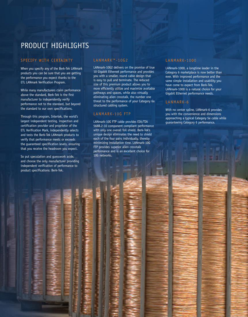
SPECIFY WITH CERTAINTY
When you specify any of the Berk-Tek LANmarkproducts you can be sure that you are gettingthe performance you expect thanks to theETL LANmark Verification Program.
While many manufacturers claim performanceabove the standard, Berk-Tek is the firstmanufacturer to independently verifyperformance not to the standard, but beyondthe standard to our own specifications.
Through this program, Intertek, the world’slargest independent testing, inspection andcertification provider and proprietor of theETL Verification Mark, independently selectsand tests the Berk-Tek LANmark products toverify that performance meets or exceedsthe guaranteed specification levels, ensuringthat you receive the headroom you expect.
So put speculation and guesswork aside,and choose the only manufacturer providingindependent verification of performance toproduct specifications: Berk-Tek.
LANMARK™-10G2
LANmark-10G2 delivers on the promise of true10 Gigabit Ethernet performance and providesyou with a smaller, round cable design thatis easy to pull and terminate. The reducedsize of this premium product allows you tomore efficiently utilize and maximize availablepathways and spaces, while also virtuallyeliminating alien crosstalk, the number onethreat to the performance of your Category 6astructured cabling system.
LANMARK-10G FTP
LANmark-10G FTP cable provides EIA/TIA568B.2-10 component compliant performancewith only one overall foil shield. Berk-Tek'sunique design eliminates the need to shieldeach of the four pairs individually, therebyminimizing installation time. LANmark-10GFTP provides superior alien crosstalkperformance and is an excellent choice for10G networks.
LANMARK-1000
LANmark-1000, a longtime leader in theCategory 6 marketplace is now better thanever. With improved performance and thesame simple installation and usability youhave come to expect from Berk-Tek,LANmark-1000 is a natural choice for yourGigabit Ethernet performance needs.
LANMARK-6
With no center spline, LANmark-6 providesyou with the convenience and dimensionsapproaching a typical Category 5e cable whileguaranteeing Category 6 performance.
PRODUCT HIGHLIGHTS
PAGE | WWW.B ERK T E K . C OM — QUICK S EAR CH : LM10G210
F E ATUR E S� Flexible, round, compact design� Alien crosstalk compliant – ETL Verified� Headroom for all crosstalk parameters� Fully compliant to Augmented Category 6 requirements� Documented balance characteristics (LCL/TCL, EL TCTL)� Reduced attenuation (Insertion Loss)� Highest-performing UTP cable available
B EN E F I TS� Easier installation and cable management with round design� Capable of reliably supporting 10GBASE-T networks� Provides bandwidth required for multimedia, broadband video,analog video and other future applications
� Balance characteristics improve overall cable performanceand reduce transmission errors
� Improved insertion loss for stronger signal to noise ratio� Characterized to 750 MHz, 250 MHz greater than the standard
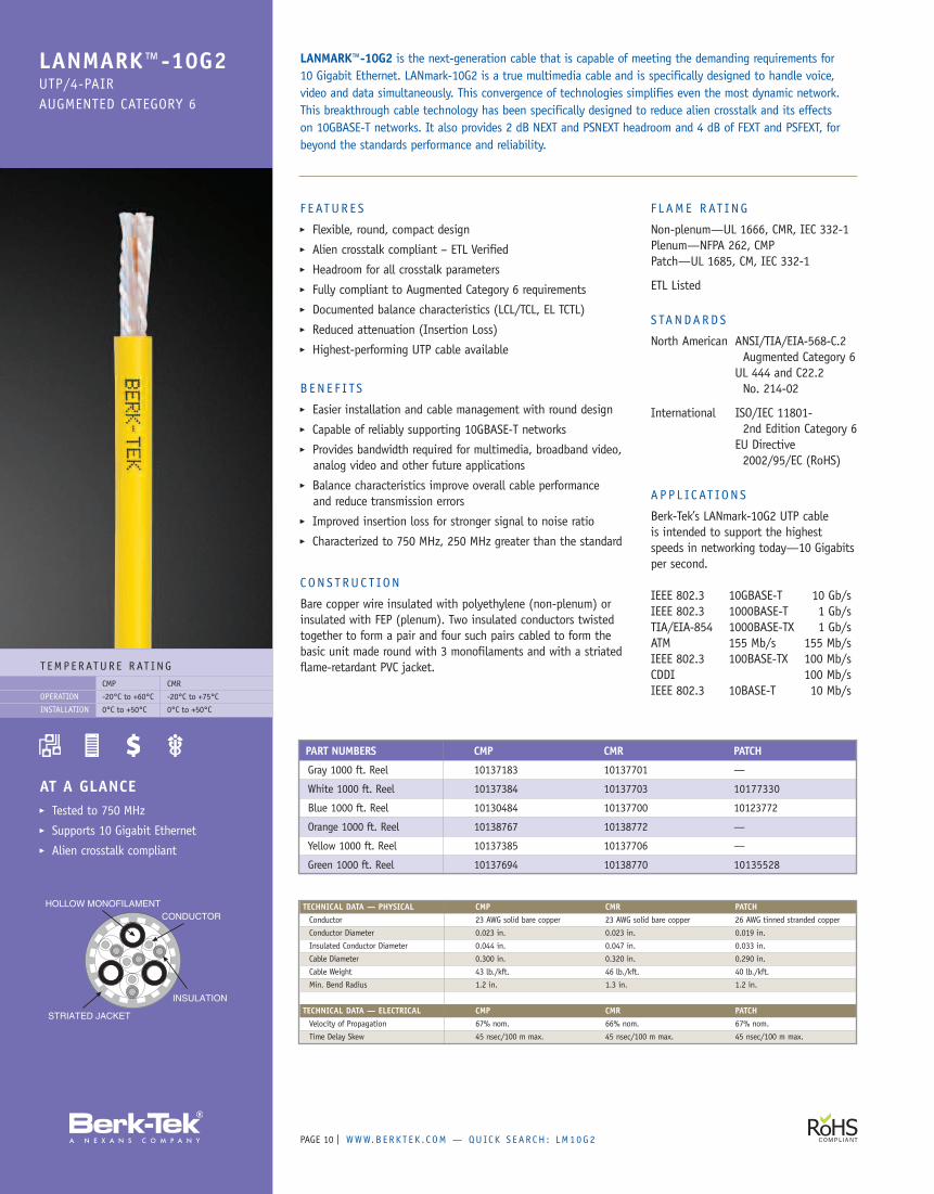
CONS T RUC T ION
Bare copper wire insulated with polyethylene (non-plenum) orinsulated with FEP (plenum). Two insulated conductors twistedtogether to form a pair and four such pairs cabled to form thebasic unit made round with 3 monofilaments and with a striatedflame-retardant PVC jacket.
F L AME RAT ING
Non-plenum—UL 1666, CMR, IEC 332-1Plenum—NFPA 262, CMPPatch—UL 1685, CM, IEC 332-1
ETL Listed
S TANDARDS
North American ANSI/TIA/EIA-568-C.2Augmented Category 6
UL 444 and C22.2No. 214-02
International ISO/IEC 11801-2nd Edition Category 6
EU Directive2002/95/EC (RoHS)
A P P L IC AT ION S
Berk-Tek’s LANmark-10G2 UTP cableis intended to support the highestspeeds in networking today—10 Gigabitsper second.
IEEE 802.3 10GBASE-T 10 Gb/sIEEE 802.3 1000BASE-T 1 Gb/sTIA/EIA-854 1000BASE-TX 1 Gb/sATM 155 Mb/s 155 Mb/sIEEE 802.3 100BASE-TX 100 Mb/sCDDI 100 Mb/sIEEE 802.3 10BASE-T 10 Mb/s
LANMARK™-10G2 is the next-generation cable that is capable of meeting the demanding requirements for10 Gigabit Ethernet. LANmark-10G2 is a true multimedia cable and is specifically designed to handle voice,video and data simultaneously. This convergence of technologies simplifies even the most dynamic network.This breakthrough cable technology has been specifically designed to reduce alien crosstalk and its effectson 10GBASE-T networks. It also provides 2 dB NEXT and PSNEXT headroom and 4 dB of FEXT and PSFEXT, forbeyond the standards performance and reliability.
T EMP ERATUR E RAT INGCMP CMR
-20°C to +60°C -20°C to +75°C
0°C to +50°C 0°C to +50°C
OPERATION
INSTALLATION
AT A GLANCE� Tested to 750 MHz� Supports 10 Gigabit Ethernet� Alien crosstalk compliant
TECHNICAL DATA — PHYSICAL CMP CMR PATCHConductor 23 AWG solid bare copper 23 AWG solid bare copper 26 AWG tinned stranded copper
Conductor Diameter 0.023 in. 0.023 in. 0.019 in.
Insulated Conductor Diameter 0.044 in. 0.047 in. 0.033 in.
Cable Diameter 0.300 in. 0.320 in. 0.290 in.
Cable Weight 43 lb./kft. 46 lb./kft. 40 lb./kft.
Min. Bend Radius 1.2 in. 1.3 in. 1.2 in.
TECHNICAL DATA — ELECTRICAL CMP CMR PATCHVelocity of Propagation 67% nom. 66% nom. 67% nom.
Time Delay Skew 45 nsec/100 m max. 45 nsec/100 m max. 45 nsec/100 m max.
PART NUMBERS CMP CMR PATCH
Gray 1000 ft. Reel 10137183 10137701 —
White 1000 ft. Reel 10137384 10137703 10177330
Blue 1000 ft. Reel 10130484 10137700 10123772
Orange 1000 ft. Reel 10138767 10138772 —
Yellow 1000 ft. Reel 10137385 10137706 —
Green 1000 ft. Reel 10137694 10138770 10135528
LANMARK™-10G2UTP/4-PAIRAUGMENTED CATEGORY 6
WWW.B ERK T E K . C OM — QUICK S EAR CH : BT 1 0G LD | PAGE 11
F E ATUR E S� Small, round OD of 0.265"� Conventional UTP cable design� Designed to work with CAT 6A connectivity� Can be installed in a common pathway with LANmark-10G2� Verified to ANSI/TIA/EIA-568-C.2-10 Category 6A (internals)
to a max. 60 meters
B EN E F I TS� Guaranteed 10G performance� No alien crosstalk testing required� Minimize pathway costs thanks to reduced OD� Improved air circulation compared to larger 10G
cable choices� Supports four-connector channel to 60 meters� Supports seven meter minimum channel length
with two connectors
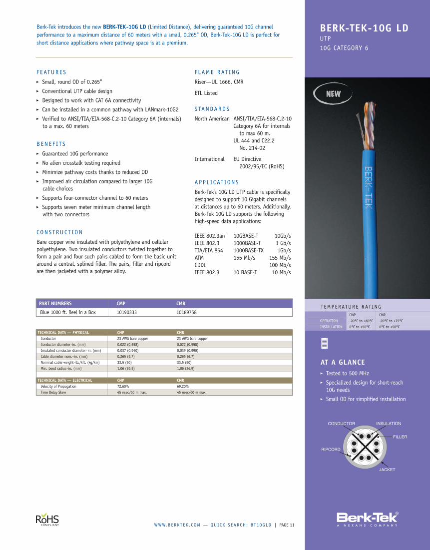
C ON S T RUC T ION
Bare copper wire insulated with polyethylene and cellularpolyethylene. Two insulated conductors twisted together toform a pair and four such pairs cabled to form the basic unitaround a central, splined filler. The pairs, filler and ripcordare then jacketed with a polymer alloy.
F L AME RAT ING
Riser—UL 1666, CMR
ETL Listed
S TANDARDS
North American ANSI/TIA/EIA-568-C.2-10Category 6A for internals
to max 60 m.UL 444 and C22.2
No. 214-02
International EU Directive2002/95/EC (RoHS)
A P P L IC AT ION S
Berk-Tek's 10G LD UTP cable is specificallydesigned to support 10 Gigabit channelsat distances up to 60 meters. Additionally,Berk-Tek 10G LD supports the followinghigh-speed data applications:
IEEE 802.3an 10GBASE-T 10Gb/sIEEE 802.3 1000BASE-T 1 Gb/sTIA/EIA 854 1000BASE-TX 1Gb/sATM 155 Mb/s 155 Mb/sCDDI 100 Mb/sIEEE 802.3 10 BASE-T 10 Mb/s
Berk-Tek introduces the new BERK-TEK-10G LD (Limited Distance), delivering guaranteed 10G channelperformance to a maximum distance of 60 meters with a small, 0.265" OD, Berk-Tek-10G LD is perfect forshort distance applications where pathway space is at a premium.
BERK-TEK-10G LDUTP10G CATEGORY 6
T EMPERATUR E RAT INGCMP CMR
-20°C to +60°C -20°C to +75°C
0°C to +50°C 0°C to +50°C
OPERATION
INSTALLATION
AT A GLANCE� Tested to 500 MHz� Specialized design for short-reach
10G needs� Small OD for simplified installation
PART NUMBERS CMP CMR
Blue 1000 ft. Reel in a Box 10190333 10189758
TECHNICAL DATA — PHYSICAL CMP CMRConductor 23 AWG bare copper 23 AWG bare copper
Conductor diameter–in. (mm) 0.022 (0.558) 0.022 (0.558)
Insulated conductor diameter–in. (mm) 0.037 (0.940) 0.039 (0.990)
Cable diameter nom.–in. (mm) 0.265 (6.7) 0.265 (6.7)
Nominal cable weight–lb./kft. (kg/km) 33.5 (50) 33.5 (50)
Min. bend radius–in. (mm) 1.06 (26.9) 1.06 (26.9)
TECHNICAL DATA — ELECTRICAL CMP CMRVelocity of Propagation 72.60% 69.20%
Time Delay Skew 45 nsec/60 m max. 45 nsec/60 m max.
PAGE | WWW.B ERK T E K . C OM — QUICK S EAR CH : LM200012
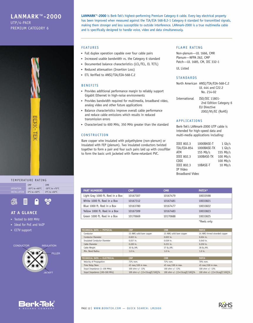
F E ATUR E S� Full duplex operation capable over four cable pairs� Increased usable bandwidth vs. the Category 6 standard� Documented balance characteristics (LCL/TCL, EL TCTL)� Reduced attenuation (Insertion Loss)� ETL Verified to ANSI/TIA/EIA-568-C.2
B EN E F I TS� Provides additional performance margin to reliably supportGigabit Ethernet in high-noise environments
� Provides bandwidth required for multimedia, broadband video,analog video and other future applications
� Balance characteristics improve overall cable performanceand reduce cable emissions which results in reducedtransmission errors
� Characterized to 600 MHz, 350 MHz greater than the standard
CONS T RUC T ION
Bare copper wire insulated with polyethylene (non-plenum) orinsulated with FEP (plenum). Two insulated conductors twistedtogether to form a pair and four such pairs laid up with crossfillerto form the basic unit jacketed with flame-retardant PVC.
F L AME RAT ING
Non-plenum—UL 1666, CMRPlenum—NFPA 262, CMPPatch—UL 1685, CM, IEC 332-1
UL Listed
S TANDARDS
North American ANSI/TIA/EIA-568-C.2UL 444 and C22.2No. 214-02
International ISO/IEC 11801-2nd Edition Category 6
EU Directive2002/95/EC (RoHS)
A P P L IC AT ION S
Berk-Tek’s LANmark-2000 UTP cable isintended for high-speed data andmulti-media applications including:
IEEE 802.3 1000BASE-T 1 Gb/sTIA/EIA-854 1000BASE-TX 1 Gb/sATM 155 Mb/s 155 Mb/sIEEE 802.3 100BASE-TX 100 Mb/sCDDI 100 Mb/sIEEE 802.3 10BASE-T 10 Mb/sIP VideoBroadband Video
LANMARK™-2000 is Berk-Tek’s highest-performing Premium Category 6 cable. Every key electrical propertyhas been improved when measured against the TIA/EIA 568-B.2-1 Category 6 standard for transmitted signals,making them stronger and less susceptible to outside interference. LANmark-2000 is a true multimedia cableand is specifically designed to handle voice, video and data simultaneously.
LANMARK™-2000UTP/4-PAIRPREMIUM CATEGORY 6
T EMPERATUR E RAT INGCMP CMR
-20°C to +60°C -20°C to +75°C
0°C to +50°C 0°C to +50°C
OPERATION
INSTALLATION
AT A GLANCE� Tested to 600 MHz� Ideal for PoE and VoIP� CCTV support
PART NUMBERS CMP CMR PATCH*
Light Gray 1000 ft. Reel in a Box 10167307 10167479 10033598
White 1000 ft. Reel in a Box 10167312 10167481 10033821
Blue 1000 ft. Reel in a Box 10163780 10167477 10033822
Yellow 1000 ft. Reel in a Box 10167309 10167483 10033823
Green 1000 ft. Reel in a Box 10170669 10170688 10033825
*Reels only
TECHNICAL DATA — PHYSICAL CMP CMR PATCHConductor 23 AWG solid bare copper 23 AWG solid bare copper 24 AWG tinned stranded copper
Conductor Diameter 0.022 in. 0.022 in. 0.024 in.
Insulated Conductor Diameter 0.037 in. 0.039 in. 0.040 in.
Cable Diameter 0.220 in. 0.231 in. 0.250 in.
Cable Weight 30 lb./kft. 27 lb./kft. 28 lb./kft.
Min. Bend Radius 1.0 in. 1.0 in. 1.0 in.
TECHNICAL DATA — ELECTRICAL CMP CMR PATCHVelocity of Propagation 72% nom. 72% nom. 70% nom.
Time Delay Skew 45 nsec/100 m max. 45 nsec/100 m max. 45 nsec/100 m max.
Input Impedance (1–100 MHz) 100 ohm +/- 13% 100 ohm +/- 13% 100 ohm +/- 13%
Input Impedance (100–500 MHz) 100 ohm +/- (13+15Log[F/100])% 100 ohm +/- (13+15Log[F/100])% 100 ohm +/- (13+15Log[F/100])%
WWW.B ERK T E K . C OM — QUICK S EAR CH : LM1000 | PAGE 13
LANMARK™-1000UTP/4-PAIRENHANCED CATEGORY 6
T EMPERATUR E RAT INGCMP CMR
-20°C to +60°C -20°C to +75°C
0°C to +50°C 0°C to +50°C
OPERATION
INSTALLATION
AT A GLANCE� Tested to 550 MHz� 1000BASE-T capable� Cable balance reduces effects of noise
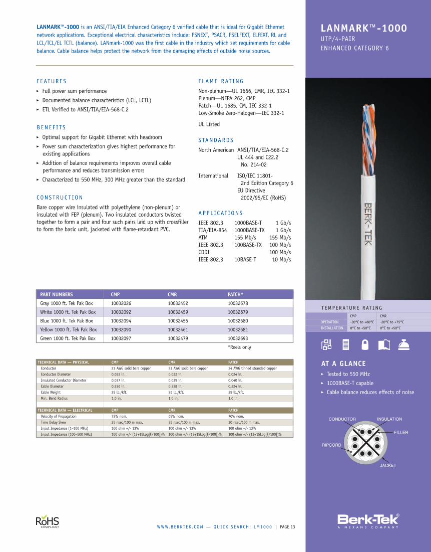
F E ATUR E S� Full power sum performance� Documented balance characteristics (LCL, LCTL)� ETL Verified to ANSI/TIA/EIA-568-C.2
B EN E F I TS� Optimal support for Gigabit Ethernet with headroom� Power sum characterization gives highest performance forexisting applications
� Addition of balance requirements improves overall cableperformance and reduces transmission errors
� Characterized to 550 MHz, 300 MHz greater than the standard
CONS T RUC T ION
Bare copper wire insulated with polyethylene (non-plenum) orinsulated with FEP (plenum). Two insulated conductors twistedtogether to form a pair and four such pairs laid up with crossfillerto form the basic unit, jacketed with flame-retardant PVC.
F L AME RAT ING
Non-plenum—UL 1666, CMR, IEC 332-1Plenum—NFPA 262, CMPPatch—UL 1685, CM, IEC 332-1Low-Smoke Zero-Halogen—IEC 332-1
UL Listed
S TANDARDS
North American ANSI/TIA/EIA-568-C.2UL 444 and C22.2No. 214-02
International ISO/IEC 11801-2nd Edition Category 6
EU Directive2002/95/EC (RoHS)
A P P L IC AT ION S
IEEE 802.3 1000BASE-T 1 Gb/sTIA/EIA-854 1000BASE-TX 1 Gb/sATM 155 Mb/s 155 Mb/sIEEE 802.3 100BASE-TX 100 Mb/sCDDI 100 Mb/sIEEE 802.3 10BASE-T 10 Mb/s
LANMARK™-1000 is an ANSI/TIA/EIA Enhanced Category 6 verified cable that is ideal for Gigabit Ethernetnetwork applications. Exceptional electrical characteristics include: PSNEXT, PSACR, PSELFEXT, ELFEXT, RL andLCL/TCL/EL TCTL (balance). LANmark-1000 was the first cable in the industry which set requirements for cablebalance. Cable balance helps protect the network from the damaging effects of outside noise sources.
PART NUMBERS CMP CMR PATCH*
Gray 1000 ft. Tek Pak Box 10032026 10032452 10032678
White 1000 ft. Tek Pak Box 10032092 10032459 10032679
Blue 1000 ft. Tek Pak Box 10032094 10032455 10032680
Yellow 1000 ft. Tek Pak Box 10032090 10032461 10032681
Green 1000 ft. Tek Pak Box 10032097 10032479 10032693
*Reels only
TECHNICAL DATA — PHYSICAL CMP CMR PATCHConductor 23 AWG solid bare copper 23 AWG solid bare copper 24 AWG tinned stranded copper
Conductor Diameter 0.022 in. 0.022 in. 0.024 in.
Insulated Conductor Diameter 0.037 in. 0.039 in. 0.040 in.
Cable Diameter 0.226 in. 0.228 in. 0.224 in.
Cable Weight 29 lb./kft. 25 lb./kft. 25 lb./kft.
Min. Bend Radius 1.0 in. 1.0 in. 1.0 in.
TECHNICAL DATA — ELECTRICAL CMP CMR PATCHVelocity of Propagation 72% nom. 69% nom. 70% nom.
Time Delay Skew 35 nsec/100 m max. 35 nsec/100 m max. 30 nsec/100 m max.
Input Impedance (1–100 MHz) 100 ohm +/- 13% 100 ohm +/- 13% 100 ohm +/- 13%
Input Impedance (100–500 MHz) 100 ohm +/- (13+15Log[F/100])% 100 ohm +/- (13+15Log[F/100])% 100 ohm +/- (13+15Log[F/100])%
PAGE | WWW.B ERK T E K . C OM — QUICK S EAR CH : LM614
T EMP ERATUR E RAT INGCMP CMR
-20°C to +60°C -20°C to +75°C
0°C to +50°C 0°C to +50°C
OPERATION
INSTALLATION
LANMARK™-6UTP/4-PAIRCATEGORY 6
AT A GLANCE� Guaranteed to 250 MHz� Cost-effective Category 6 solution� No center spline
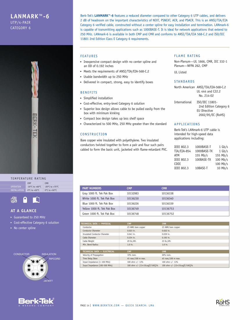
F EATUR E S� Inexpensive compact design with no center spline andan OD of 0.192 inches
� Meets the requirements of ANSI/TIA/EIA-568-C.2� Usable bandwidth up to 250 MHz� Delivered in compact, strong, easy to identify boxes
B EN E F I TS� Simplified installation� Cost-effective, entry-level Category 6 solution� Superior box design allows cable to be pulled easily from thebox with minimum kinking
� Compact box design takes up less shelf space� Characterized to 500 MHz, 250 MHz greater than the standard
CONS T RUC T ION
Bare copper wire insulated with polyethylene. Two insulatedconductors twisted together to form a pair and four such pairscabled to form the basic unit, jacketed with flame-retardant PVC.
F L AME RAT ING
Non-Plenum—UL 1666, CMR, IEC 332-1Plenum—NFPA 262, CMP
UL Listed
S TANDARDS
North American ANSI/TIA/EIA-568-C.2UL 444 and C22.2No. 214-02
International ISO/IEC 11801-2nd Edition Category 6
EU Directive2002/95/EC (RoHS)
A P P L IC AT ION S
Berk-Tek’s LANmark-6 UTP cable isintended for high-speed dataapplications including:
IEEE 802.3 1000BASE-T 1 Gb/sTIA/EIA-854 1000BASE-TX 1 Gb/sATM 155 Mb/s 155 Mb/sIEEE 802.3 100BASE-TX 100 Mb/sCDDI 100 Mb/sIEEE 802.3 10BASE-T 10 Mb/s
Berk-Tek’s LANMARK™-6 features a reduced diameter compared to other Category 6 UTP cables, and delivers2 dB of headroom on the important characteristics of NEXT, PSNEXT, ACR, and PSACR. This is an ANSI/TIA/EIACategory 6 verified cable, constructed without a center spline for easy installation and termination. LANmark-6is capable of transmitting applications such as 1000BASE-T. It is ideal for network applications that extend to250 MHz. LANmark-6 is available in both CMP and CMR and conforms to ANSI/TIA/EIA 568-C.2 and ISO/IEC11801 2nd Edition Class E Category 6 requirements.
TECHNICAL DATA — PHYSICAL CMP CMRConductor 23 AWG bare copper 23 AWG bare copper
Conductor Diameter 0.023 in. 0.022 in.
Insulated Conductor Diameter 0.041 in. 0.039 in.
Cable Diameter 0.224 in. 0.192 in.
Cable Weight 29 lb./kft. 23 lb./kft.
Min. Bend Radius 1.0 in. 1.0 in.
TECHNICAL DATA — ELECTRICAL CMP CMRVelocity of Propagation 72% nom. 69% nom.
Time Delay Skew 45 nsec/100 m max. 45 nsec/100 m max.
Input Impedance (1–100 MHz) 100 ohm +/- 13% 100 ohm +/- 13%
Input Impedance (100–500 MHz) 100 ohm +/- (13+15Log[F/100])% 100 ohm +/- (13+15Log[F/100])%
PART NUMBERS CMP CMR
Gray 1000 ft. Tek Pak Box 10132983 10136338
White 1000 ft. Tek Pak Box 10136230 10136340
Blue 1000 ft. Tek Pak Box 10136226 10136339
Yellow 1000 ft. Tek Pak Box 10136749 10136753
Green 1000 ft. Tek Pak Box 10136748 10136752
WWW.B ERK T E K . C OM — QUICK S EAR CH : LM6OSP | PAGE 15
T EMP ERATUR E RAT INGOSP
-40°C to +70°C
0°C to +60°C
OPERATION
INSTALLATION
LANMARK™-6 OSPUTP/4-PAIRCATEGORY 6 OSP
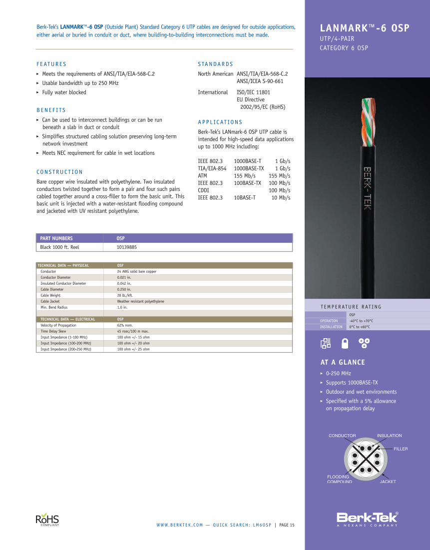
AT A GLANCE� 0-250 MHz� Supports 1000BASE-TX� Outdoor and wet environments� Specified with a 5% allowanceon propagation delay
F EATUR E S� Meets the requirements of ANSI/TIA/EIA-568-C.2� Usable bandwidth up to 250 MHz� Fully water blocked
B EN E F I TS� Can be used to interconnect buildings or can be runbeneath a slab in duct or conduit
� Simplifies structured cabling solution preserving long-termnetwork investment
� Meets NEC requirement for cable in wet locations
CONS T RUC T ION
Bare copper wire insulated with polyethylene. Two insulatedconductors twisted together to form a pair and four such pairscabled together around a cross-filler to form the basic unit. Thisbasic unit is injected with a water-resistant flooding compoundand jacketed with UV resistant polyethylene.
S TANDARDS
North American ANSI/TIA/EIA-568-C.2ANSI/ICEA S-90-661
International ISO/IEC 11801EU Directive2002/95/EC (RoHS)
A P P L IC AT ION S
Berk-Tek’s LANmark-6 OSP UTP cable isintended for high-speed data applicationsup to 1000 MHz including:
IEEE 802.3 1000BASE-T 1 Gb/sTIA/EIA-854 1000BASE-TX 1 Gb/sATM 155 Mb/s 155 Mb/sIEEE 802.3 100BASE-TX 100 Mb/sCDDI 100 Mb/sIEEE 802.3 10BASE-T 10 Mb/s
Berk-Tek’s LANMARK™-6 OSP (Outside Plant) Standard Category 6 UTP cables are designed for outside applications,either aerial or buried in conduit or duct, where building-to-building interconnections must be made.
PART NUMBERS OSP
Black 1000 ft. Reel 10139885
TECHNICAL DATA — PHYSICAL OSPConductor 24 AWG solid bare copper
Conductor Diameter 0.021 in.
Insulated Conductor Diameter 0.042 in.
Cable Diameter 0.250 in.
Cable Weight 28 lb./kft.
Cable Jacket Weather resistant polyethylene
Min. Bend Radius 1.0 in.
TECHNICAL DATA — ELECTRICAL OSPVelocity of Propagation 62% nom.
Time Delay Skew 45 nsec/100 m max.
Input Impedance (1-100 MHz) 100 ohm +/- 15 ohm
Input Impedance (100-200 MHz) 100 ohm +/- 20 ohm
Input Impedance (200-250 MHz) 100 ohm +/- 25 ohm
PAGE | WWW.B ERK T E K . C OM — QUICK S EAR CH : LM35016
T EMP ERATUR E RAT INGCMP CMR
-20°C to +60°C -20°C to +75°C
0°C to +50°C 0°C to +50°C
OPERATION
INSTALLATION
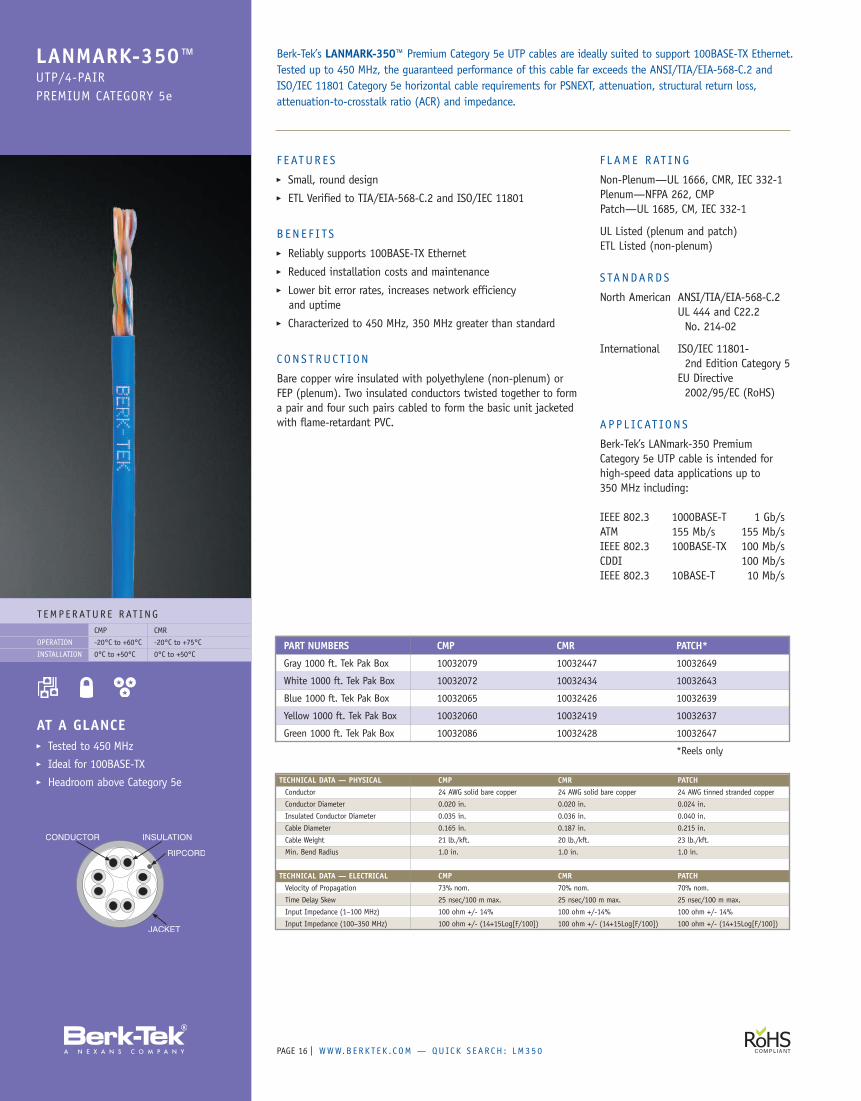
LANMARK-350™UTP/4-PAIRPREMIUM CATEGORY 5e
AT A GLANCE� Tested to 450 MHz� Ideal for 100BASE-TX� Headroom above Category 5e
F EATUR E S� Small, round design� ETL Verified to TIA/EIA-568-C.2 and ISO/IEC 11801
B EN E F I TS� Reliably supports 100BASE-TX Ethernet� Reduced installation costs and maintenance� Lower bit error rates, increases network efficiencyand uptime
� Characterized to 450 MHz, 350 MHz greater than standard
CONS T RUC T ION
Bare copper wire insulated with polyethylene (non-plenum) orFEP (plenum). Two insulated conductors twisted together to forma pair and four such pairs cabled to form the basic unit jacketedwith flame-retardant PVC.
F L AME RAT ING
Non-Plenum—UL 1666, CMR, IEC 332-1Plenum—NFPA 262, CMPPatch—UL 1685, CM, IEC 332-1
UL Listed (plenum and patch)ETL Listed (non-plenum)
S TANDARDS
North American ANSI/TIA/EIA-568-C.2UL 444 and C22.2No. 214-02
International ISO/IEC 11801-2nd Edition Category 5
EU Directive2002/95/EC (RoHS)
A P P L IC AT ION S
Berk-Tek’s LANmark-350 PremiumCategory 5e UTP cable is intended forhigh-speed data applications up to350 MHz including:
IEEE 802.3 1000BASE-T 1 Gb/sATM 155 Mb/s 155 Mb/sIEEE 802.3 100BASE-TX 100 Mb/sCDDI 100 Mb/sIEEE 802.3 10BASE-T 10 Mb/s
Berk-Tek’s LANMARK-350™ Premium Category 5e UTP cables are ideally suited to support 100BASE-TX Ethernet.Tested up to 450 MHz, the guaranteed performance of this cable far exceeds the ANSI/TIA/EIA-568-C.2 andISO/IEC 11801 Category 5e horizontal cable requirements for PSNEXT, attenuation, structural return loss,attenuation-to-crosstalk ratio (ACR) and impedance.
PART NUMBERS CMP CMR PATCH*
Gray 1000 ft. Tek Pak Box 10032079 10032447 10032649
White 1000 ft. Tek Pak Box 10032072 10032434 10032643
Blue 1000 ft. Tek Pak Box 10032065 10032426 10032639
Yellow 1000 ft. Tek Pak Box 10032060 10032419 10032637
Green 1000 ft. Tek Pak Box 10032086 10032428 10032647
*Reels only
TECHNICAL DATA — PHYSICAL CMP CMR PATCHConductor 24 AWG solid bare copper 24 AWG solid bare copper 24 AWG tinned stranded copper
Conductor Diameter 0.020 in. 0.020 in. 0.024 in.
Insulated Conductor Diameter 0.035 in. 0.036 in. 0.040 in.
Cable Diameter 0.165 in. 0.187 in. 0.215 in.
Cable Weight 21 lb./kft. 20 lb./kft. 23 lb./kft.
Min. Bend Radius 1.0 in. 1.0 in. 1.0 in.
TECHNICAL DATA — ELECTRICAL CMP CMR PATCHVelocity of Propagation 73% nom. 70% nom. 70% nom.
Time Delay Skew 25 nsec/100 m max. 25 nsec/100 m max. 25 nsec/100 m max.
Input Impedance (1–100 MHz) 100 ohm +/- 14% 100 ohm +/-14% 100 ohm +/- 14%
Input Impedance (100–350 MHz) 100 ohm +/- (14+15Log[F/100]) 100 ohm +/- (14+15Log[F/100]) 100 ohm +/- (14+15Log[F/100])
WWW.B ERK T E K . C OM — QUICK S EAR CH : H Y P 5 E | PAGE 17
T EMP ERATUR E RAT INGCMP CMR
-20°C to +60°C -20°C to +75°C
0°C to +50°C 0°C to +50°C
OPERATION
INSTALLATION
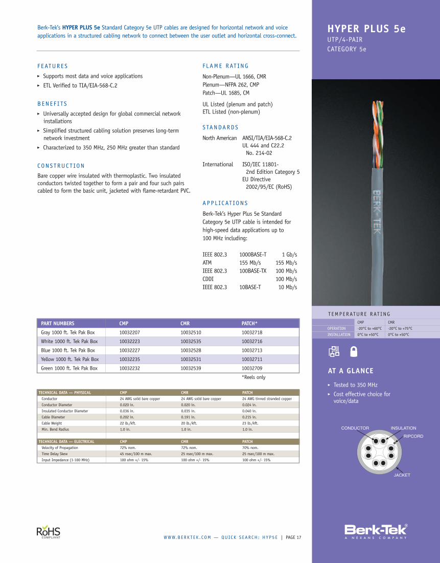
HYPER PLUS 5eUTP/4-PAIRCATEGORY 5e
AT A GLANCE
� Tested to 350 MHz� Cost effective choice forvoice/data
F EATUR E S� Supports most data and voice applications� ETL Verified to TIA/EIA-568-C.2
B EN E F I TS� Universally accepted design for global commercial networkinstallations
� Simplified structured cabling solution preserves long-termnetwork investment
� Characterized to 350 MHz, 250 MHz greater than standard
CONS T RUC T ION
Bare copper wire insulated with thermoplastic. Two insulatedconductors twisted together to form a pair and four such pairscabled to form the basic unit, jacketed with flame-retardant PVC.
F L AME RAT ING
Non-Plenum—UL 1666, CMRPlenum—NFPA 262, CMPPatch—UL 1685, CM
UL Listed (plenum and patch)ETL Listed (non-plenum)
S TANDARDS
North American ANSI/TIA/EIA-568-C.2UL 444 and C22.2No. 214-02
International ISO/IEC 11801-2nd Edition Category 5
EU Directive2002/95/EC (RoHS)
A P P L IC AT ION S
Berk-Tek’s Hyper Plus 5e StandardCategory 5e UTP cable is intended forhigh-speed data applications up to100 MHz including:
IEEE 802.3 1000BASE-T 1 Gb/sATM 155 Mb/s 155 Mb/sIEEE 802.3 100BASE-TX 100 Mb/sCDDI 100 Mb/sIEEE 802.3 10BASE-T 10 Mb/s
Berk-Tek’s HYPER PLUS 5e Standard Category 5e UTP cables are designed for horizontal network and voiceapplications in a structured cabling network to connect between the user outlet and horizontal cross-connect.
PART NUMBERS CMP CMR PATCH*
Gray 1000 ft. Tek Pak Box 10032207 10032510 10032718
White 1000 ft. Tek Pak Box 10032223 10032535 10032716
Blue 1000 ft. Tek Pak Box 10032227 10032528 10032713
Yellow 1000 ft. Tek Pak Box 10032235 10032531 10032711
Green 1000 ft. Tek Pak Box 10032232 10032539 10032709
*Reels only
TECHNICAL DATA — PHYSICAL CMP CMR PATCHConductor 24 AWG solid bare copper 24 AWG solid bare copper 24 AWG tinned stranded copper
Conductor Diameter 0.020 in. 0.020 in. 0.024 in.
Insulated Conductor Diameter 0.036 in. 0.035 in. 0.040 in.
Cable Diameter 0.202 in. 0.191 in. 0.215 in.
Cable Weight 22 lb./kft. 20 lb./kft. 23 lb./kft.
Min. Bend Radius 1.0 in. 1.0 in. 1.0 in.
TECHNICAL DATA — ELECTRICAL CMP CMR PATCHVelocity of Propagation 72% nom. 72% nom. 70% nom.
Time Delay Skew 45 nsec/100 m max. 25 nsec/100 m max. 25 nsec/100 m max.
Input Impedance (1-100 MHz) 100 ohm +/- 15% 100 ohm +/- 15% 100 ohm +/- 15%
PAGE | WWW.B ERK T E K . C OM — QUICK S EAR CH : H Y PO S P18
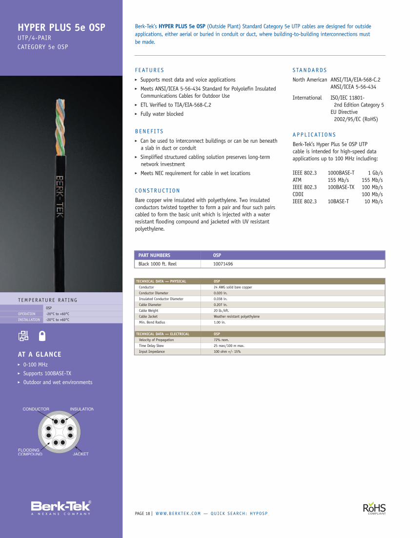
T EMP ERATUR E RAT INGOSP
-20°C to +60°C
-20°C to +60°C
OPERATION
INSTALLATION
AT A GLANCE� 0-100 MHz� Supports 100BASE-TX� Outdoor and wet environments
HYPER PLUS 5e OSPUTP/4-PAIRCATEGORY 5e OSP
F EATUR E S� Supports most data and voice applications� Meets ANSI/ICEA 5-56-434 Standard for Polyolefin InsulatedCommunications Cables for Outdoor Use
� ETL Verified to TIA/EIA-568-C.2� Fully water blocked
B EN E F I TS� Can be used to interconnect buildings or can be run beneatha slab in duct or conduit
� Simplified structured cabling solution preserves long-termnetwork investment
� Meets NEC requirement for cable in wet locations
CONS T RUC T ION
Bare copper wire insulated with polyethylene. Two insulatedconductors twisted together to form a pair and four such pairscabled to form the basic unit which is injected with a waterresistant flooding compound and jacketed with UV resistantpolyethylene.
Berk-Tek’s HYPER PLUS 5e OSP (Outside Plant) Standard Category 5e UTP cables are designed for outsideapplications, either aerial or buried in conduit or duct, where building-to-building interconnections mustbe made.
S TANDARDS
North American ANSI/TIA/EIA-568-C.2ANSI/ICEA 5-56-434
International ISO/IEC 11801-2nd Edition Category 5
EU Directive2002/95/EC (RoHS)
A P P L IC AT ION S
Berk-Tek’s Hyper Plus 5e OSP UTPcable is intended for high-speed dataapplications up to 100 MHz including:
IEEE 802.3 1000BASE-T 1 Gb/sATM 155 Mb/s 155 Mb/sIEEE 802.3 100BASE-TX 100 Mb/sCDDI 100 Mb/sIEEE 802.3 10BASE-T 10 Mb/s
PART NUMBERS OSP
Black 1000 ft. Reel 10071496
TECHNICAL DATA — PHYSICAL OSPConductor 24 AWG solid bare copper
Conductor Diameter 0.020 in.
Insulated Conductor Diameter 0.038 in.
Cable Diameter 0.207 in.
Cable Weight 20 lb./kft.
Cable Jacket Weather resistant polyethylene
Min. Bend Radius 1.00 in.
TECHNICAL DATA — ELECTRICAL OSPVelocity of Propagation 72% nom.
Time Delay Skew 25 nsec/100 m max.
Input Impedance 100 ohm +/- 15%
WWW.B ERK T E K . C OM — QUICK S EAR CH : 4 P R CAT 3 | PAGE 19
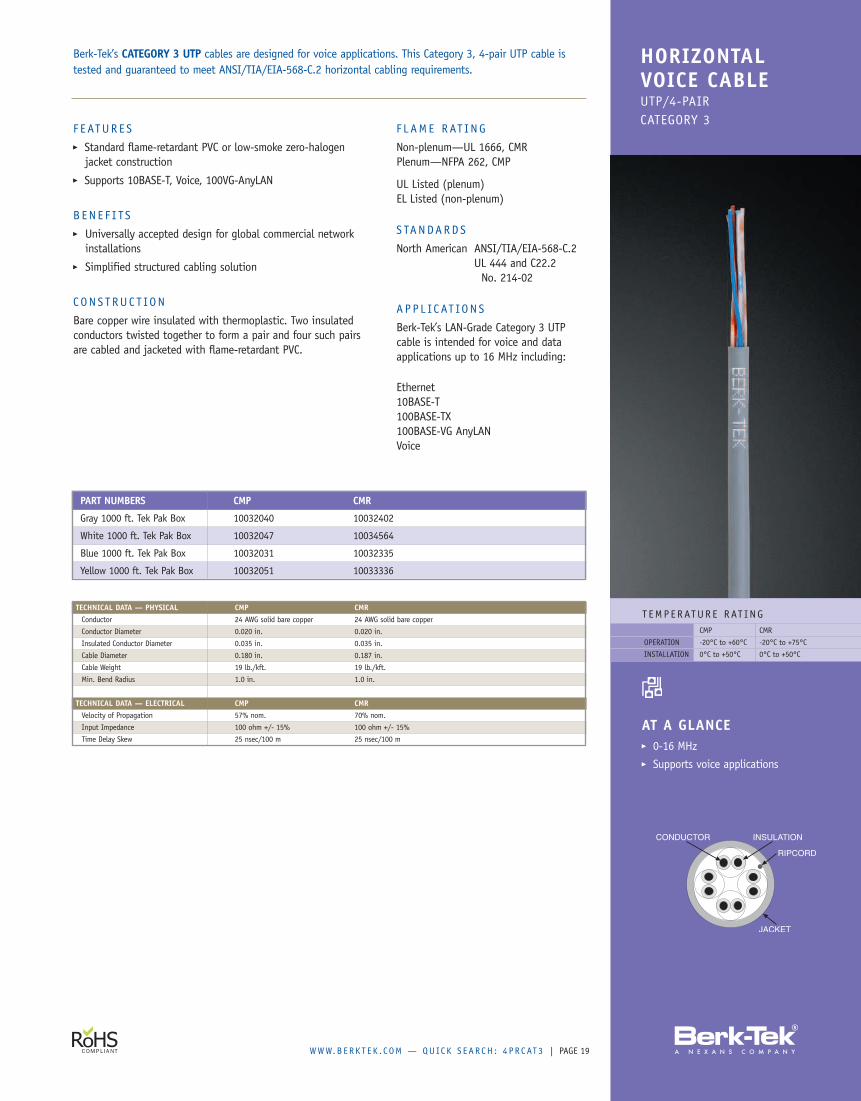
T EMP ERATUR E RAT INGCMP CMR
-20°C to +60°C -20°C to +75°C
0°C to +50°C 0°C to +50°C
OPERATION
INSTALLATION
AT A GLANCE� 0-16 MHz� Supports voice applications
HORIZONTALVOICE CABLEUTP/4-PAIRCATEGORY 3
F EATUR E S� Standard flame-retardant PVC or low-smoke zero-halogenjacket construction
� Supports 10BASE-T, Voice, 100VG-AnyLAN
BENE F I TS� Universally accepted design for global commercial networkinstallations
� Simplified structured cabling solution
CONS T RUC T ION
Bare copper wire insulated with thermoplastic. Two insulatedconductors twisted together to form a pair and four such pairsare cabled and jacketed with flame-retardant PVC.
F L AME RAT ING
Non-plenum—UL 1666, CMRPlenum—NFPA 262, CMP
UL Listed (plenum)EL Listed (non-plenum)
S TANDARDS
North American ANSI/TIA/EIA-568-C.2UL 444 and C22.2No. 214-02
APP L IC AT ION S
Berk-Tek’s LAN-Grade Category 3 UTPcable is intended for voice and dataapplications up to 16 MHz including:
Ethernet10BASE-T100BASE-TX100BASE-VG AnyLANVoice
Berk-Tek’s CATEGORY 3 UTP cables are designed for voice applications. This Category 3, 4-pair UTP cable istested and guaranteed to meet ANSI/TIA/EIA-568-C.2 horizontal cabling requirements.
PART NUMBERS CMP CMR
Gray 1000 ft. Tek Pak Box 10032040 10032402
White 1000 ft. Tek Pak Box 10032047 10034564
Blue 1000 ft. Tek Pak Box 10032031 10032335
Yellow 1000 ft. Tek Pak Box 10032051 10033336
TECHNICAL DATA — PHYSICAL CMP CMRConductor 24 AWG solid bare copper 24 AWG solid bare copper
Conductor Diameter 0.020 in. 0.020 in.
Insulated Conductor Diameter 0.035 in. 0.035 in.
Cable Diameter 0.180 in. 0.187 in.
Cable Weight 19 lb./kft. 19 lb./kft.
Min. Bend Radius 1.0 in. 1.0 in.
TECHNICAL DATA — ELECTRICAL CMP CMRVelocity of Propagation 57% nom. 70% nom.
Input Impedance 100 ohm +/- 15% 100 ohm +/- 15%
Time Delay Skew 25 nsec/100 m 25 nsec/100 m
PAGE | WWW.B ERK T E K . C OM — QUICK S EAR CH : P S 2 5 PR5 E20
T EMP ERATUR E RAT INGCMP CMR
-50°C to +200°C -20°C to +75°C
-50°C to +200°C 0°C to +50°C
OPERATION
INSTALLATION
AT A GLANCE� Tested to 250 MHz� Ideal for data centerinterconnects
� Zone cabling� Small, flexible design
POWER SUMUTP/25-PAIRCATEGORY 5e
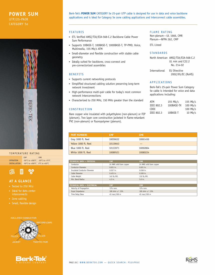
F EATUR E S� ETL Verified ANSI/TIA/EIA-568-C.2 Backbone Cable PowerSum Performance
� Supports 10BASE-T, 100BASE-T, 1000BASE-T, TP-PMD, Voice,Multimedia, 155 Mb/s ATM
� Small-diameter and flexible construction with stable cablegeometry
� Ideally suited for backbone, cross-connect andpre-connectorized assemblies
B EN E F I TS� Supports current networking protocols� Simplified structured cabling solution preserving long-termnetwork investment
� High-performance multi-pair cable for today’s most commonnetwork interconnections
� Characterized to 250 MHz, 150 MHz greater than the standard
CONS T RUC T ION
Bare copper wire insulated with polyethylene (non-plenum) or FEP(plenum). Two layer core construction jacketed in flame-retardantPVC (non-plenum) or fluoropolymer (plenum).
F L AME RAT INGNon-plenum—UL 1666, CMRPlenum—NFPA 262, CMP
ETL Listed
S TANDARDS
North American ANSI/TIA/EIA-568-C.2UL 444 and C22.2No. 214-02
International EU Directive2002/95/EC (RoHS)
A P P L IC AT ION S
Berk-Tek’s 25-pair Power Sum Category5e cable is intended for voice and dataapplications including:
ATM 155 Mb/s 155 Mb/sIEEE 802.3 100BASE-TX 100 Mb/sCDDI 100 Mb/sIEEE 802.3 10BASE-T 10 Mb/s
Berk-Tek’s POWER SUM CATEGORY 5e 25-pair UTP cable is designed for use in data and voice backboneapplications and is ideal for Category 5e zone cabling applications and interconnect cable assemblies.
PART NUMBERS CMP CMR
Gray 1000 ft. Reel 10059632 10061456
Yellow 1000 ft. Reel 10119643 —
Blue 1000 ft. Reel 10133971 10092804
White 1000 ft. Reel 10089521 10080224
TECHNICAL DATA — PHYSICAL CMP CMRConductor 24 AWG solid bare copper 24 AWG solid bare copper
Conductor Diameter 0.021 in. 0.021 in.
Insulated Conductor Diameter 0.037 in. 0.038 in.
Cable Diameter 0.455 in. 0.500 in.
Cable Weight 142 lb./kft. 132 lb./kft.
Min. Bend Radius 4.5 in. 5.0 in.
TECHNICAL DATA — ELECTRICAL CMP CMRVelocity of Propagation 72% nom. 72% nom.
Input Impedance 100 ohm +/- 15% 100 ohm +/- 15%
Time Delay Skew 45 nsec/100 m 45 nsec/100 m
WWW.B ERK T E K . C OM — QUICK S EAR CH : H I P R CAT 3 | PAGE 21
T EMP ERATUR E RAT ING-20°C to +60°C
0°C to +50°C
OPERATION
INSTALLATION
AT A GLANCE� 0-16 MHz� Ideal interconnect cable� Voice backbone� Cost effective design
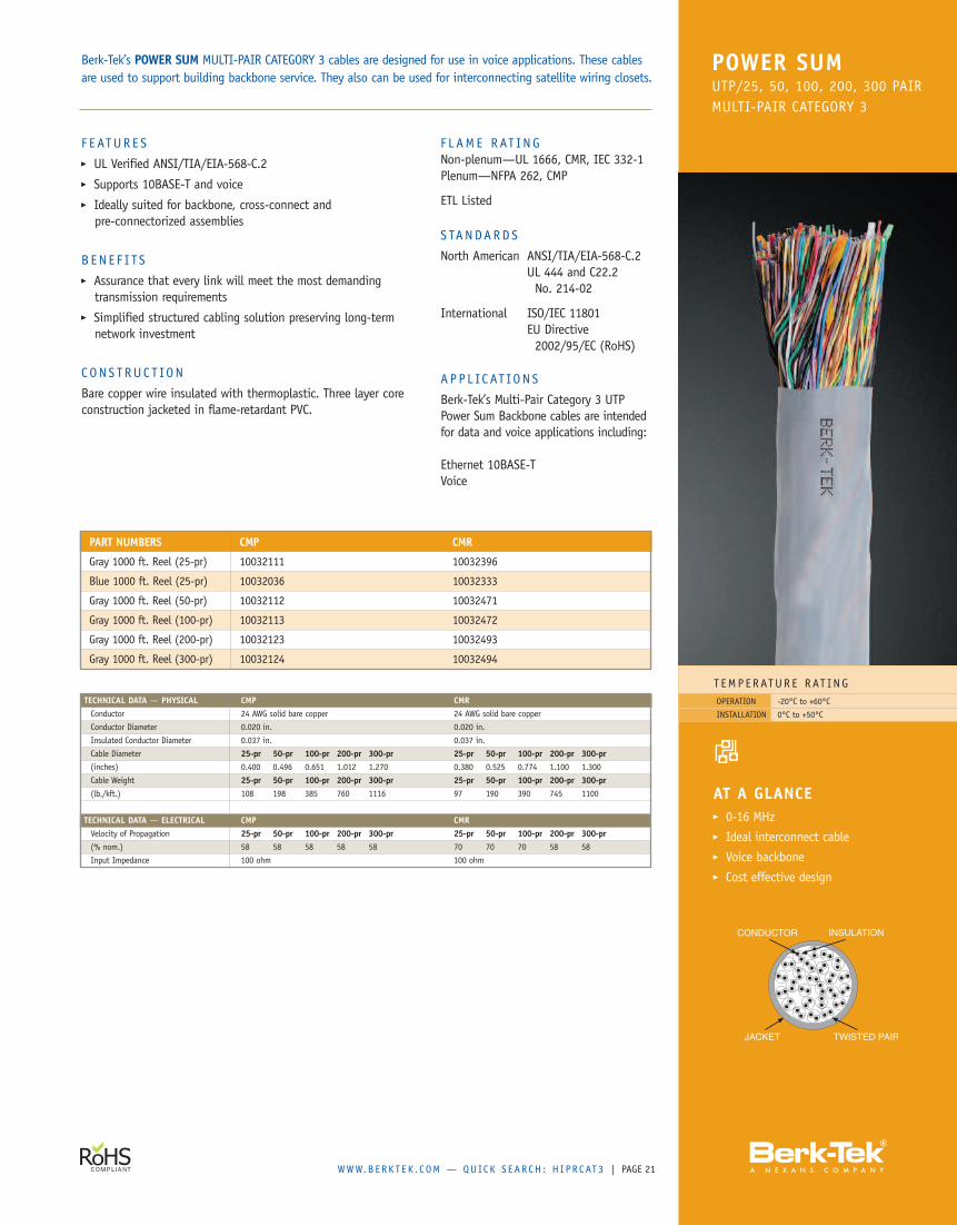
POWER SUMUTP/25, 50, 100, 200, 300 PAIRMULTI-PAIR CATEGORY 3
PART NUMBERS CMP CMR
Gray 1000 ft. Reel (25-pr) 10032111 10032396
Blue 1000 ft. Reel (25-pr) 10032036 10032333
Gray 1000 ft. Reel (50-pr) 10032112 10032471
Gray 1000 ft. Reel (100-pr) 10032113 10032472
Gray 1000 ft. Reel (200-pr) 10032123 10032493
Gray 1000 ft. Reel (300-pr) 10032124 10032494
F L AME RAT INGNon-plenum—UL 1666, CMR, IEC 332-1Plenum—NFPA 262, CMP
ETL Listed
S TANDARDS
North American ANSI/TIA/EIA-568-C.2UL 444 and C22.2No. 214-02
International ISO/IEC 11801EU Directive2002/95/EC (RoHS)
A P P L IC AT ION S
Berk-Tek’s Multi-Pair Category 3 UTPPower Sum Backbone cables are intendedfor data and voice applications including:
Ethernet 10BASE-TVoice
Berk-Tek’s POWER SUM MULTI-PAIR CATEGORY 3 cables are designed for use in voice applications. These cablesare used to support building backbone service. They also can be used for interconnecting satellite wiring closets.
TECHNICAL DATA — PHYSICAL CMP CMRConductor 24 AWG solid bare copper 24 AWG solid bare copper
Conductor Diameter 0.020 in. 0.020 in.
Insulated Conductor Diameter 0.037 in. 0.037 in.
Cable Diameter 25-pr 50-pr 100-pr 200-pr 300-pr 25-pr 50-pr 100-pr 200-pr 300-pr(inches) 0.400 0.496 0.651 1.012 1.270 0.380 0.525 0.774 1.100 1.300
Cable Weight 25-pr 50-pr 100-pr 200-pr 300-pr 25-pr 50-pr 100-pr 200-pr 300-pr(lb./kft.) 108 198 385 760 1116 97 190 390 745 1100
TECHNICAL DATA — ELECTRICAL CMP CMRVelocity of Propagation 25-pr 50-pr 100-pr 200-pr 300-pr 25-pr 50-pr 100-pr 200-pr 300-pr(% nom.) 58 58 58 58 58 70 70 70 58 58
Input Impedance 100 ohm 100 ohm
F E ATUR E S� UL Verified ANSI/TIA/EIA-568-C.2� Supports 10BASE-T and voice� Ideally suited for backbone, cross-connect andpre-connectorized assemblies
B EN E F I TS� Assurance that every link will meet the most demandingtransmission requirements
� Simplified structured cabling solution preserving long-termnetwork investment
CONS T RUC T ION
Bare copper wire insulated with thermoplastic. Three layer coreconstruction jacketed in flame-retardant PVC.
PAGE | WWW.B ERK T E K . C OM — QUICK S EAR CH : 4 0 0 PR22
T EMP ERATUR E RAT ING-20°C to +60°C
0°C to +50°C
OPERATION
INSTALLATION
AT A GLANCE� 0-16 MHz� Ideal interconnect cable� Voice backbone� Cost effective design
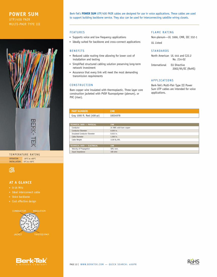
POWER SUMUTP/400 PAIRMULTI-PAIR TYPE III
F EATUR E S� Supports voice and low frequency applications� Ideally suited for backbone and cross-connect applications
B EN E F I TS� Reduced cable routing time allowing for lower cost ofinstallation and testing
� Simplified structured cabling solution preserving long-termnetwork investment
� Assurance that every link will meet the most demandingtransmission requirements
C ON S T RUC T ION
Bare copper wire insulated with thermoplastic. Three layer coreconstruction jacketed with PVDF fluoropolymer (plenum), orPVC (riser).
F L AME RAT ING
Non-plenum—UL 1666, CMR, IEC 332-1
UL Listed
S TANDARDS
North American UL 444 and C22.2No. 214-02
International EU Directive2002/95/EC (RoHS)
A P P L IC AT ION S
Berk-Tek’s Multi-Pair Type III PowerSum UTP cables are intended for voiceapplications.
Berk-Tek’s POWER SUM UTP/400 PAIR cables are designed for use in voice applications. These cables are usedto support building backbone service. They also can be used for interconnecting satellite wiring closets.
PART NUMBERS CMR
Gray 1000 ft. Reel (400-pr) 10034978
TECHNICAL DATA — PHYSICAL CMRConductor 24 AWG solid bare copper
Conductor Diameter 0.020 in.
Insulated Conductor Diameter 0.033 in.
Cable Diameter 1.500 in.
Cable Weight 1130 lb./kft.
TECHNICAL DATA — ELECTRICAL CMRVelocity of Propagation 58% nom.
Input Impedance 100 ohm
WWW.B ERK T E K . C OM — QUICK S EAR CH : LM10G F T P | PAGE 23
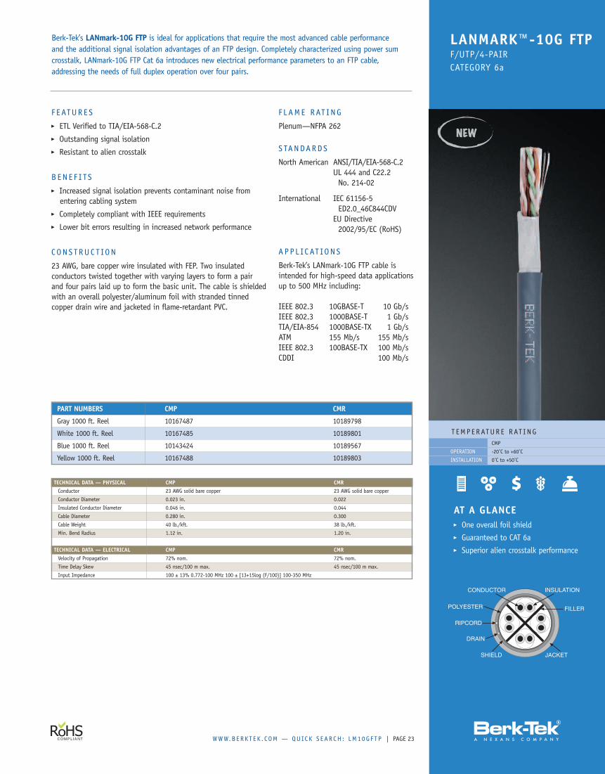
F E ATUR E S� ETL Verified to TIA/EIA-568-C.2� Outstanding signal isolation� Resistant to alien crosstalk
B EN E F I TS� Increased signal isolation prevents contaminant noise fromentering cabling system
� Completely compliant with IEEE requirements� Lower bit errors resulting in increased network performance
CONS T RUC T ION
23 AWG, bare copper wire insulated with FEP. Two insulatedconductors twisted together with varying layers to form a pairand four pairs laid up to form the basic unit. The cable is shieldedwith an overall polyester/aluminum foil with stranded tinnedcopper drain wire and jacketed in flame-retardant PVC.
F L AME RAT ING
Plenum—NFPA 262
S TANDARDS
North American ANSI/TIA/EIA-568-C.2UL 444 and C22.2No. 214-02
International IEC 61156-5ED2.0_46C844CDV
EU Directive2002/95/EC (RoHS)
A P P L IC AT ION S
Berk-Tek’s LANmark-10G FTP cable isintended for high-speed data applicationsup to 500 MHz including:
IEEE 802.3 10GBASE-T 10 Gb/sIEEE 802.3 1000BASE-T 1 Gb/sTIA/EIA-854 1000BASE-TX 1 Gb/sATM 155 Mb/s 155 Mb/sIEEE 802.3 100BASE-TX 100 Mb/sCDDI 100 Mb/s
T EMP ERATUR E RAT INGCMP
-20˚C to +60˚C
0˚C to +50˚C
OPERATION
INSTALLATION
Berk-Tek’s LANmark-10G FTP is ideal for applications that require the most advanced cable performanceand the additional signal isolation advantages of an FTP design. Completely characterized using power sumcrosstalk, LANmark-10G FTP Cat 6a introduces new electrical performance parameters to an FTP cable,addressing the needs of full duplex operation over four pairs.
LANMARK™-10G FTPF/UTP/4-PAIRCATEGORY 6a
TECHNICAL DATA — PHYSICAL CMP CMRConductor 23 AWG solid bare copper 23 AWG solid bare copper
Conductor Diameter 0.023 in. 0.022
Insulated Conductor Diameter 0.046 in. 0.044
Cable Diameter 0.280 in. 0.300
Cable Weight 40 lb./kft. 38 lb./kft.
Min. Bend Radius 1.12 in. 1.20 in.
TECHNICAL DATA — ELECTRICAL CMP CMRVelocity of Propagation 72% nom. 72% nom.
Time Delay Skew 45 nsec/100 m max. 45 nsec/100 m max.
Input Impedance 100 ± 13% 0.772-100 MHz 100 ± [13+15log (F/100)] 100-350 MHz
PART NUMBERS CMP CMR
Gray 1000 ft. Reel 10167487 10189798
White 1000 ft. Reel 10167485 10189801
Blue 1000 ft. Reel 10143424 10189567
Yellow 1000 ft. Reel 10167488 10189803
AT A GLANCE� One overall foil shield� Guaranteed to CAT 6a� Superior alien crosstalk performance
PAGE | WWW.B ERK T E K . C OM — QUICK S EAR CH : LM6 F T P24
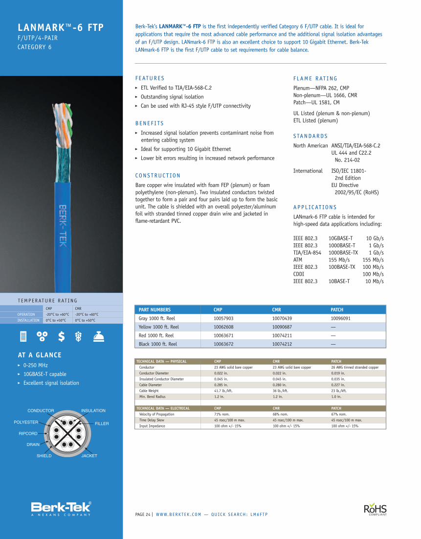
F E ATUR E S� ETL Verified to TIA/EIA-568-C.2� Outstanding signal isolation� Can be used with RJ-45 style F/UTP connectivity
B EN E F I TS� Increased signal isolation prevents contaminant noise fromentering cabling system
� Ideal for supporting 10 Gigabit Ethernet� Lower bit errors resulting in increased network performance
CONS T RUC T ION
Bare copper wire insulated with foam FEP (plenum) or foampolyethylene (non-plenum). Two insulated conductors twistedtogether to form a pair and four pairs laid up to form the basicunit. The cable is shielded with an overall polyester/aluminumfoil with stranded tinned copper drain wire and jacketed inflame-retardant PVC.
F L AME RAT ING
Plenum—NFPA 262, CMPNon-plenum—UL 1666, CMRPatch—UL 1581, CM
UL Listed (plenum & non-plenum)ETL Listed (plenum)
S TANDARDS
North American ANSI/TIA/EIA-568-C.2UL 444 and C22.2No. 214-02
International ISO/IEC 11801-2nd Edition
EU Directive2002/95/EC (RoHS)
A P P L IC AT ION S
LANmark-6 FTP cable is intended forhigh-speed data applications including:
IEEE 802.3 10GBASE-T 10 Gb/sIEEE 802.3 1000BASE-T 1 Gb/sTIA/EIA-854 1000BASE-TX 1 Gb/sATM 155 Mb/s 155 Mb/sIEEE 802.3 100BASE-TX 100 Mb/sCDDI 100 Mb/sIEEE 802.3 10BASE-T 10 Mb/s
AT A GLANCE� 0-250 MHz� 10GBASE-T capable� Excellent signal isolation
Berk-Tek’s LANMARK™-6 FTP is the first independently verified Category 6 F/UTP cable. It is ideal forapplications that require the most advanced cable performance and the additional signal isolation advantagesof an F/UTP design. LANmark-6 FTP is also an excellent choice to support 10 Gigabit Ethernet. Berk-TekLANmark-6 FTP is the first F/UTP cable to set requirements for cable balance.
LANMARK™-6 FTPF/UTP/4-PAIRCATEGORY 6
PART NUMBERS CMP CMR PATCH
Gray 1000 ft. Reel 10057903 10070439 10096091
Yellow 1000 ft. Reel 10062608 10090687 —
Red 1000 ft. Reel 10063671 10074211 —
Black 1000 ft. Reel 10063672 10074212 —
TECHNICAL DATA — PHYSICAL CMP CMR PATCHConductor 23 AWG solid bare copper 23 AWG solid bare copper 26 AWG tinned stranded copper
Conductor Diameter 0.022 in. 0.022 in. 0.019 in.
Insulated Conductor Diameter 0.045 in. 0.045 in. 0.035 in.
Cable Diameter 0.285 in. 0.280 in. 0.227 in.
Cable Weight 41.7 lb./kft. 36 lb./kft. 23 lb./kft.
Min. Bend Radius 1.2 in. 1.2 in. 1.0 in.
TECHNICAL DATA — ELECTRICAL CMP CMR PATCHVelocity of Propagation 71% nom. 68% nom. 67% nom.
Time Delay Skew 45 nsec/100 m max. 45 nsec/100 m max. 45 nsec/100 m max.
Input Impedance 100 ohm +/- 15% 100 ohm +/- 15% 100 ohm +/- 15%
T EMP ERATUR E RAT INGCMP CMR
-20°C to +60°C -20°C to +60°C
0°C to +50°C 0°C to +50°C
OPERATION
INSTALLATION
WWW.B ERK T E K . C OM — QUICK S EAR CH : LM5 E F T P | PAGE 25
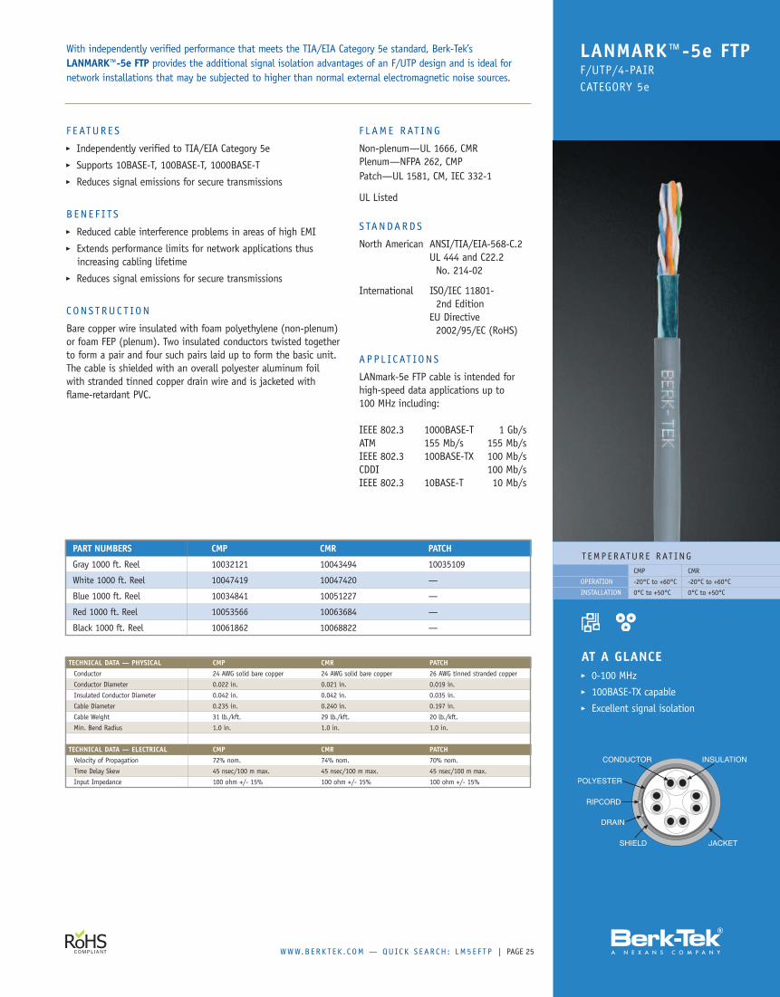
F E ATUR E S� Independently verified to TIA/EIA Category 5e� Supports 10BASE-T, 100BASE-T, 1000BASE-T� Reduces signal emissions for secure transmissions
B EN E F I TS� Reduced cable interference problems in areas of high EMI� Extends performance limits for network applications thusincreasing cabling lifetime
� Reduces signal emissions for secure transmissions
CONS T RUC T ION
Bare copper wire insulated with foam polyethylene (non-plenum)or foam FEP (plenum). Two insulated conductors twisted togetherto form a pair and four such pairs laid up to form the basic unit.The cable is shielded with an overall polyester aluminum foilwith stranded tinned copper drain wire and is jacketed withflame-retardant PVC.
F L AME RAT ING
Non-plenum—UL 1666, CMRPlenum—NFPA 262, CMPPatch—UL 1581, CM, IEC 332-1
UL Listed
S TANDARDS
North American ANSI/TIA/EIA-568-C.2UL 444 and C22.2No. 214-02
International ISO/IEC 11801-2nd Edition
EU Directive2002/95/EC (RoHS)
A P P L IC AT ION S
LANmark-5e FTP cable is intended forhigh-speed data applications up to100 MHz including:
IEEE 802.3 1000BASE-T 1 Gb/sATM 155 Mb/s 155 Mb/sIEEE 802.3 100BASE-TX 100 Mb/sCDDI 100 Mb/sIEEE 802.3 10BASE-T 10 Mb/s
T EMP ERATUR E RAT INGCMP CMR
-20°C to +60°C -20°C to +60°C
0°C to +50°C 0°C to +50°C
OPERATION
INSTALLATION
AT A GLANCE� 0-100 MHz� 100BASE-TX capable� Excellent signal isolation
With independently verified performance that meets the TIA/EIA Category 5e standard, Berk-Tek’sLANMARK™-5e FTP provides the additional signal isolation advantages of an F/UTP design and is ideal fornetwork installations that may be subjected to higher than normal external electromagnetic noise sources.
LANMARK™-5e FTPF/UTP/4-PAIRCATEGORY 5e
PART NUMBERS CMP CMR PATCH
Gray 1000 ft. Reel 10032121 10043494 10035109
White 1000 ft. Reel 10047419 10047420 —
Blue 1000 ft. Reel 10034841 10051227 —
Red 1000 ft. Reel 10053566 10063684 —
Black 1000 ft. Reel 10061862 10068822 —
TECHNICAL DATA — PHYSICAL CMP CMR PATCHConductor 24 AWG solid bare copper 24 AWG solid bare copper 26 AWG tinned stranded copper
Conductor Diameter 0.022 in. 0.021 in. 0.019 in.
Insulated Conductor Diameter 0.042 in. 0.042 in. 0.035 in.
Cable Diameter 0.235 in. 0.240 in. 0.197 in.
Cable Weight 31 lb./kft. 29 lb./kft. 20 lb./kft.
Min. Bend Radius 1.0 in. 1.0 in. 1.0 in.
TECHNICAL DATA — ELECTRICAL CMP CMR PATCHVelocity of Propagation 72% nom. 74% nom. 70% nom.
Time Delay Skew 45 nsec/100 m max. 45 nsec/100 m max. 45 nsec/100 m max.
Input Impedance 100 ohm +/- 15% 100 ohm +/- 15% 100 ohm +/- 15%
PAGE | WWW.B ERK T E K . C OM — QUICK S EAR CH : T 126
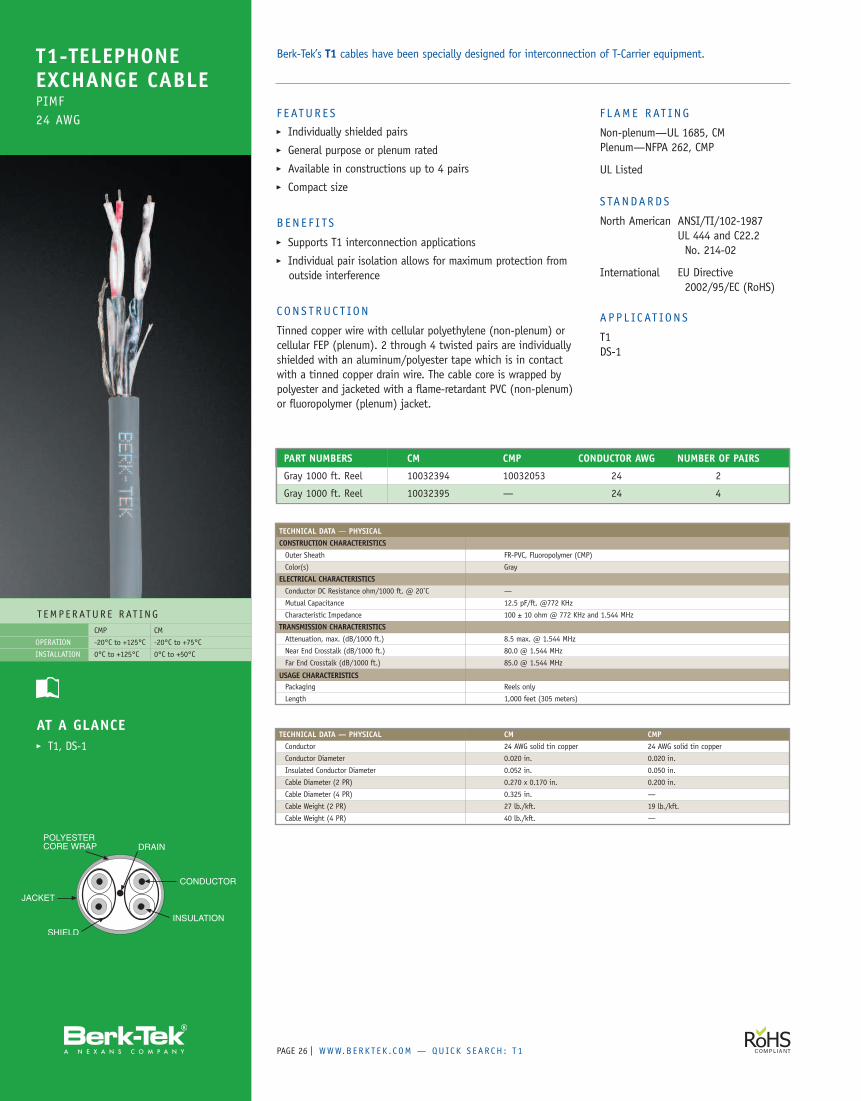
F E ATUR E S� Individually shielded pairs� General purpose or plenum rated� Available in constructions up to 4 pairs� Compact size
B EN E F I TS� Supports T1 interconnection applications� Individual pair isolation allows for maximum protection fromoutside interference
CONS T RUC T ION
Tinned copper wire with cellular polyethylene (non-plenum) orcellular FEP (plenum). 2 through 4 twisted pairs are individuallyshielded with an aluminum/polyester tape which is in contactwith a tinned copper drain wire. The cable core is wrapped bypolyester and jacketed with a flame-retardant PVC (non-plenum)or fluoropolymer (plenum) jacket.
F L AME RAT ING
Non-plenum—UL 1685, CMPlenum—NFPA 262, CMP
UL Listed
S TANDARDS
North American ANSI/TI/102-1987UL 444 and C22.2No. 214-02
International EU Directive2002/95/EC (RoHS)
A P P L IC AT ION S
T1DS-1
T EMP ERATUR E RAT INGCMP CM
-20°C to +125°C -20°C to +75°C
0°C to +125°C 0°C to +50°C
OPERATION
INSTALLATION
AT A GLANCE� T1, DS-1
Berk-Tek’s T1 cables have been specially designed for interconnection of T-Carrier equipment.T1-TELEPHONEEXCHANGE CABLEPIMF24 AWG
PART NUMBERS CM CMP CONDUCTOR AWG NUMBER OF PAIRS
Gray 1000 ft. Reel 10032394 10032053 24 2
Gray 1000 ft. Reel 10032395 — 24 4
TECHNICAL DATA — PHYSICAL CM CMPConductor 24 AWG solid tin copper 24 AWG solid tin copper
Conductor Diameter 0.020 in. 0.020 in.
Insulated Conductor Diameter 0.052 in. 0.050 in.
Cable Diameter (2 PR) 0.270 x 0.170 in. 0.200 in.
Cable Diameter (4 PR) 0.325 in. —
Cable Weight (2 PR) 27 lb./kft. 19 lb./kft.
Cable Weight (4 PR) 40 lb./kft. —
TECHNICAL DATA — PHYSICALCONSTRUCTION CHARACTERISTICSOuter Sheath FR-PVC, Fluoropolymer (CMP)
Color(s) Gray
ELECTRICAL CHARACTERISTICSConductor DC Resistance ohm/1000 ft. @ 20˚C —
Mutual Capacitance 12.5 pF/ft. @772 KHz
Characteristic Impedance 100 ± 10 ohm @ 772 KHz and 1.544 MHz
TRANSMISSION CHARACTERISTICSAttenuation, max. (dB/1000 ft.) 8.5 max. @ 1.544 MHz
Near End Crosstalk (dB/1000 ft.) 80.0 @ 1.544 MHz
Far End Crosstalk (dB/1000 ft.) 85.0 @ 1.544 MHz
USAGE CHARACTERISTICSPackaging Reels only
Length 1,000 feet (305 meters)
WWW.B ERK T E K . C OM — QUICK S EAR CH : L OWSK EW | PAGE 27
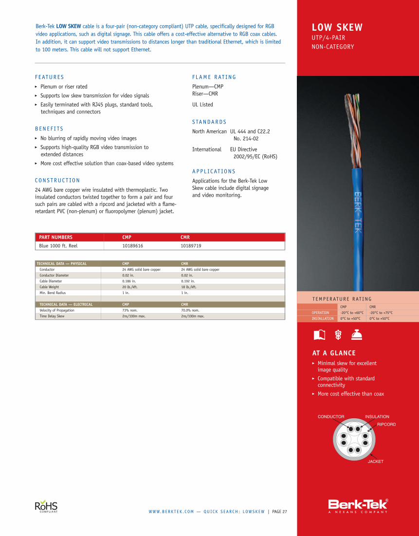
AT A GLANCE� Minimal skew for excellentimage quality
� Compatible with standardconnectivity
� More cost effective than coax
Berk-Tek LOW SKEW cable is a four-pair (non-category compliant) UTP cable, specifically designed for RGBvideo applications, such as digital signage. This cable offers a cost-effective alternative to RGB coax cables.In addition, it can support video transmissions to distances longer than traditional Ethernet, which is limitedto 100 meters. This cable will not support Ethernet.
LOW SKEWUTP/4-PAIRNON-CATEGORY
PART NUMBERS CMP CMR
Blue 1000 ft. Reel 10189616 10189719
T EMP ERATUR E RAT INGCMP CMR
-20°C to +60°C -20°C to +75°C
0°C to +50°C 0°C to +50°C
OPERATION
INSTALLATION
F E ATUR E S� Plenum or riser rated� Supports low skew transmission for video signals� Easily terminated with RJ45 plugs, standard tools,techniques and connectors
B EN E F I TS� No blurring of rapidly moving video images� Supports high-quality RGB video transmission toextended distances
� More cost effective solution than coax-based video systems
CONS T RUC T ION
24 AWG bare copper wire insulated with thermoplastic. Twoinsulated conductors twisted together to form a pair and foursuch pairs are cabled with a ripcord and jacketed with a flame-retardant PVC (non-plenum) or fluoropolymer (plenum) jacket.
F L AME RAT ING
Plenum—CMPRiser—CMR
UL Listed
S TANDARDS
North American UL 444 and C22.2No. 214-02
International EU Directive2002/95/EC (RoHS)
A P P L IC AT ION S
Applications for the Berk-Tek LowSkew cable include digital signageand video monitoring.
TECHNICAL DATA — PHYSICAL CMP CMRConductor 24 AWG solid bare copper 24 AWG solid bare copper
Conductor Diameter 0.02 in. 0.02 in.
Cable Diameter 0.186 in. 0.192 in.
Cable Weight 20 lb./kft. 18 lb./kft.
Min. Bend Radius 1 in. 1 in.
TECHNICAL DATA — ELECTRICAL CMP CMRVelocity of Propagation 73% nom. 70.0% nom.
Time Delay Skew 2ns/100m max. 2ns/100m max.
PAGE | WWW.B ERK T E K . C OM28
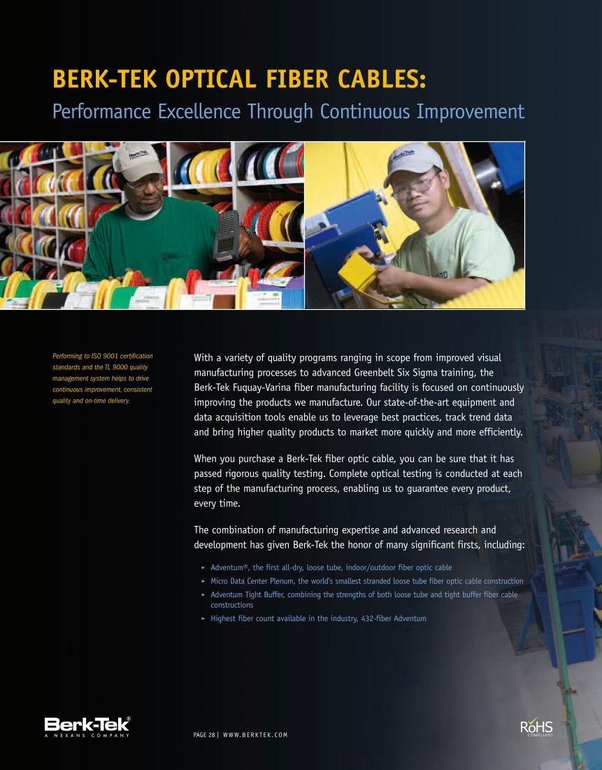
BERK-TEK OPTICAL FIBER CABLES:Performance Excellence Through Continuous Improvement
Performing to ISO 9001 certification
standards and the TL 9000 quality
management system helps to drive
continuous improvement, consistent
quality and on-time delivery.
With a variety of quality programs ranging in scope from improved visualmanufacturing processes to advanced Greenbelt Six Sigma training, theBerk-Tek Fuquay-Varina fiber manufacturing facility is focused on continuouslyimproving the products we manufacture. Our state-of-the-art equipment anddata acquisition tools enable us to leverage best practices, track trend dataand bring higher quality products to market more quickly and more efficiently.
When you purchase a Berk-Tek fiber optic cable, you can be sure that it haspassed rigorous quality testing. Complete optical testing is conducted at eachstep of the manufacturing process, enabling us to guarantee every product,every time.
The combination of manufacturing expertise and advanced research anddevelopment has given Berk-Tek the honor of many significant firsts, including:
� Adventum®, the first all-dry, loose tube, indoor/outdoor fiber optic cable� Micro Data Center Plenum, the world’s smallest stranded loose tube fiber optic cable construction� Adventum Tight Buffer, combining the strengths of both loose tube and tight buffer fiber cableconstructions
� Highest fiber count available in the industry, 432-fiber Adventum
MICRO DATA CENTER PLENUM
For installations where space is at a premium,like data centers and storage area networks,Berk-Tek has created just the right cable, theMicro Data Center Plenum cable. The uniquedesign has been granted a patent by theUSPTO #7, 609, 926. This cable is up to 50%smaller than typical loose tube, premisesdistribution or ribbon cable designs ofcomparable strand counts. As important asits small size, is its rugged constructionthat allows for effective utilization of spacewithout giving up the pulling strengthneeded for a trouble-free installation.
COMPOSITE SECURITY CABLE
With the convergence of CCTV, buildingautomation systems and other security
applications onto the structured cablingsystem, there is a clear need for a cable thatcan power a camera while also providing theperformance of optical fiber. The Berk-TekComposite Security cable delivers both highbandwidth optical performance and power tocameras, access or monitoring devices at adistance up to 6000 feet.
ADVENTUM® TIGHT BUFFER
The unique design of the Adventum TightBuffer cable combines the strengths of theAdventum Indoor/Outdoor cable with theconvenience of tight-buffered fibers. The cableis fully water blocked with the Berk-Tek DryGelwater-blocking system, which means no messygels to clean. And the tight buffer fiberconstruction means quick, direct terminationwith no need for fan out kits. This is an
ideal cable for FTTx applications such asmulti-dwelling or multi-tenant units, or itcan be used for security applications.
ADVENTUM
Berk-Tek continues to improve and expandupon the success of the AdventumIndoor/Outdoor fiber optic cable. For certainstrand counts we have been able to reduceboth the outer diameter and the cable weightthrough the removal of unnecessary buffertubes. There is now a side-by-side design forour 24-fiber cables that is more flexiblethan a traditional round design and allowsfor better conduit fill ratios. Finally, wecontinue to extend the range of availablefiber counts, with Adventum plenum cable upto 432 fibers.
PRODUCT HIGHLIGHTS
PAGE | WWW.B ERK T E K . C OM30
Visit us online at www.berktek.com/teklab to easily configure yourassembly, generate a part number and schematic, and request a quotation.TekLAB is designed to help you easily configure the exact pre-terminated cable assemblies you need for all your projects. Simplyclick on “Configure” to build your assembly, generate the schematic, request a quote and place your order through the distributor ofyour choice. The online quotation and ordering system ensures prompt response from the Berk-Tek dedicated customer service team.
With the hassle-free installation and error-free performanceof Berk-Tek Pre-Terminated Fiber Cable Assemblies,maximizing your project ROI has never been easier.
R EDUC E T IM E TO D E P LOY, IM PROV E PRO J E C T RO I
For projects of any variety, from the largest data center, to a typicaloffice Local Area Network (LAN) or a campus-wide network, you don’thave time to waste. You need materials on hand, on time, and inproper working order.
And that’s where Berk-Tek Pre-Terminated Fiber Optic Cable Assembliesenter the picture.
We start with our full-line of superior fiber optic cables, addtop-of-the-line connectors, construct assemblies to your exactspecifications, and test every piece before it leaves our hands.Then they are shipped directly to your job site where theyare ready for immediate installation. It really is that easy.
F E ATUR E S
� Wide variety of cable and connector options available� Full-range of optical fiber types, from GIGAlite-10XBEnhanced Multimode through standard 62.5 micron multimodeand single-mode
� True custom designs, easily configured online� Fully tested, labeled and documented� Installation requires no consumables, termination tool kitsor specialized termination training
� Factory installed pulling eyes available� Armored cable assemblies available with integral bonding wires
B EN E F I T S
� Rapidly deployable with no cable preparation required� Ready for installation on arrival� Lower installation cost� Lower cost of ownership� No cable or connector scrap� No termination errors� Improved end-to-end attenuation, throughput and applicationmigration with higher-performing factory terminated connectors
� Improved link loss budgets
AP P L I C AT I ON S
� Interbuilding and Intrabuilding backbones for LAN Premisesand Campus applications
� Data center, Main and Horizontal cross connects, zone and equipmentdistribution area trunk cables for Storage Area Network (SAN) applications
� Extended Multimode distance guarantees for:• 100 Gb/s Ethernet, parallel assemblies• 40 Gb/s Ethernet, parallel assemblies• 10GBase-SR Ethernet LAN applications• 1000Base-LX Ethernet LAN applications• 1000Base-SX Ethernet LAN applications• 10 Gb/s Fibre Channel SAN applications• 4.25 Gb/s Fibre Channel SAN applications• 2.12 Gb/s Fibre Channel SAN applications• 1.06 Gb/s Fibre Channel SAN applications
PRE-TERMINATED MULTI-FIBER CABLES AT A GLANCE
WWW.B ERK T E K . C OM | PAGE 31
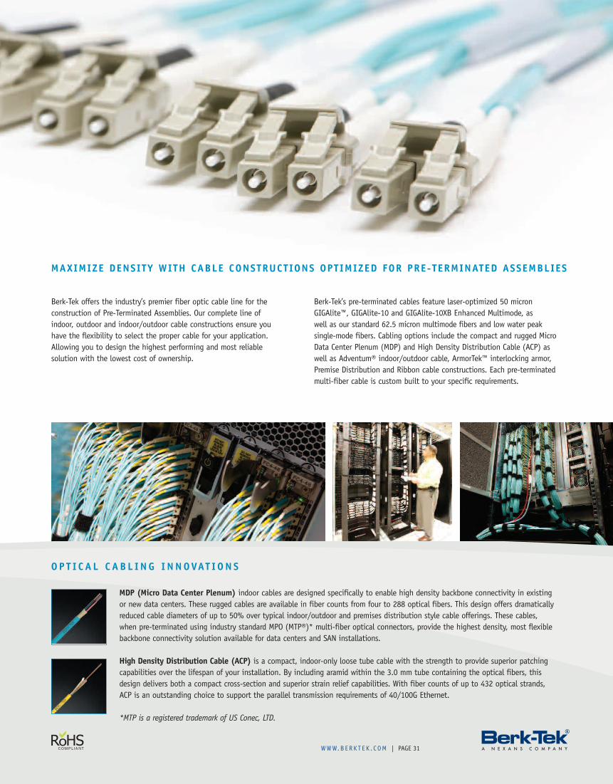
MAXIMIZE DENSITY WITH CABLE CONSTRUCTIONS OPTIMIZED FOR PRE-TERMINATED ASSEMBLIES
Berk-Tek offers the industry’s premier fiber optic cable line for theconstruction of Pre-Terminated Assemblies. Our complete line ofindoor, outdoor and indoor/outdoor cable constructions ensure youhave the flexibility to select the proper cable for your application.Allowing you to design the highest performing and most reliablesolution with the lowest cost of ownership.
Berk-Tek’s pre-terminated cables feature laser-optimized 50 micronGIGAlite™, GIGAlite-10 and GIGAlite-10XB Enhanced Multimode, aswell as our standard 62.5 micron multimode fibers and low water peaksingle-mode fibers. Cabling options include the compact and rugged MicroData Center Plenum (MDP) and High Density Distribution Cable (ACP) aswell as Adventum® indoor/outdoor cable, ArmorTek™ interlocking armor,Premise Distribution and Ribbon cable constructions. Each pre-terminatedmulti-fiber cable is custom built to your specific requirements.
MDP (Micro Data Center Plenum) indoor cables are designed specifically to enable high density backbone connectivity in existingor new data centers. These rugged cables are available in fiber counts from four to 288 optical fibers. This design offers dramaticallyreduced cable diameters of up to 50% over typical indoor/outdoor and premises distribution style cable offerings. These cables,when pre-terminated using industry standard MPO (MTP®)* multi-fiber optical connectors, provide the highest density, most flexiblebackbone connectivity solution available for data centers and SAN installations.
High Density Distribution Cable (ACP) is a compact, indoor-only loose tube cable with the strength to provide superior patchingcapabilities over the lifespan of your installation. By including aramid within the 3.0 mm tube containing the optical fibers, thisdesign delivers both a compact cross-section and superior strain relief capabilities. With fiber counts of up to 432 optical strands,ACP is an outstanding choice to support the parallel transmission requirements of 40/100G Ethernet.
*MTP is a registered trademark of US Conec, LTD.
OP T I C A L C AB L I NG I NNOVAT I ON S
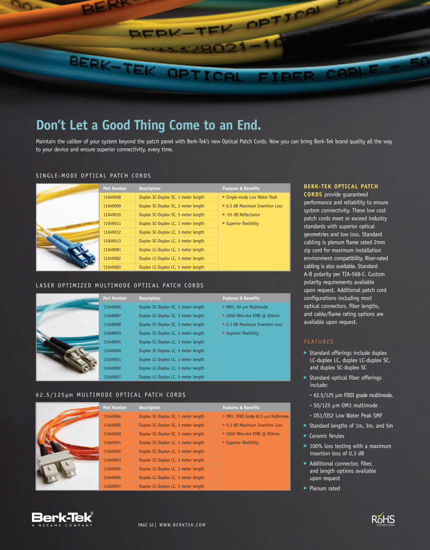
PAGE | WWW.B ERK T E K . C OM32
S I NG L E -MODE OP T IC A L PATCH CORDS
Part Number Description Features & Benefits
11049008 Duplex SC-Duplex SC, 1 meter length � Single-mode Low Water Peak
11049009 Duplex SC-Duplex SC, 3 meter length � 0.3 dB Maximum Insertion Loss
11049010 Duplex SC-Duplex SC, 5 meter length � -55 dB Reflectance
11049011 Duplex SC-Duplex LC, 1 meter length � Superior flexibility
11049012 Duplex SC-Duplex LC, 3 meter length
11049013 Duplex SC-Duplex LC, 5 meter length
11049081 Duplex LC-Duplex LC, 1 meter length
11049082 Duplex LC-Duplex LC, 3 meter length
11049083 Duplex LC-Duplex LC, 5 meter length
L A S E R OP T IM I Z ED MULT IMODE OP T ICA L PATCH CORDS
62 . 5 / 1 2 5µm MULT IMODE OP T ICA L PATCH CORDS
Part Number Description Features & Benefits
11048986 Duplex SC-Duplex SC, 1 meter length � OM3, 50 µm Multimode
11048987 Duplex SC-Duplex SC, 3 meter length � 2000 MHz•km EMB @ 850nm
11048988 Duplex SC-Duplex SC, 5 meter length � 0.3 dB Maximum Insertion Loss
11048993 Duplex SC-Duplex LC, 1 meter length � Superior flexibility
11048994 Duplex SC-Duplex LC, 3 meter length
11049000 Duplex SC-Duplex LC, 5 meter length
11049001 Duplex LC-Duplex LC, 1 meter length
11049002 Duplex LC-Duplex LC, 3 meter length
11049007 Duplex LC-Duplex LC, 5 meter length
Part Number Description Features & Benefits
11049084 Duplex SC-Duplex SC, 1 meter length � OM1, FDDI Grade 62.5 µm Multimode
11049085 Duplex SC-Duplex SC, 3 meter length � 0.3 dB Maximum Insertion Loss
11049090 Duplex SC-Duplex SC, 5 meter length � 2000 MHz•km EMB @ 850nm
11049091 Duplex SC-Duplex LC, 1 meter length � Superior flexibility
11049092 Duplex SC-Duplex LC, 3 meter length
11049093 Duplex SC-Duplex LC, 5 meter length
11049094 Duplex LC-Duplex LC, 1 meter length
11049096 Duplex LC-Duplex LC, 3 meter length
11049097 Duplex LC-Duplex LC, 5 meter length
Don’t Let a Good Thing Come to an End.Maintain the caliber of your system beyond the patch panel with Berk-Tek’s new Optical Patch Cords. Now you can bring Berk-Tek brand quality all the wayto your device and ensure superior connectivity, every time.
BERK-TEK OPTICAL PATCHCORDS provide guaranteedperformance and reliability to ensuresystem connectivity. These low costpatch cords meet or exceed industrystandards with superior opticalgeometries and low loss. Standardcabling is plenum flame rated 2mmzip cord for maximum installationenvironment compatibility. Riser-ratedcabling is also available. StandardA-B polarity per TIA-568-C. Custompolarity requirements availableupon request. Additional patch cordconfigurations including mostoptical connectors, fiber lengths,and cable/flame rating options areavailable upon request.
F E ATUR E S
� Standard offerings include duplexLC-duplex LC, duplex LC-duplex SC,and duplex SC-duplex SC
� Standard optical fiber offeringsinclude:
• 62.5/125 µm FDDI grade multimode,
• 50/125 µm OM3 multimode
• OS1/OS2 Low Water Peak SMF
� Standard lengths of 1m, 3m, and 5m
� Ceramic ferules
� 100% loss testing with a maximuminsertion loss of 0.3 dB
� Additional connector, fiber,and length options availableupon request
� Plenum rated
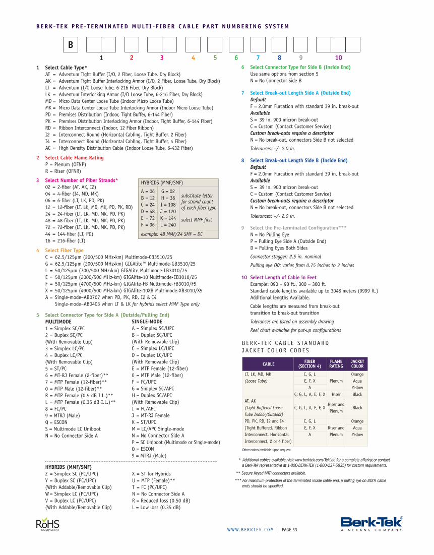
WWW.B ERK T E K . C OM | PAGE 33
4 Select Fiber TypeC = 62.5/125µm (200/500 MHz•km) Multimode-CB3510/25G = 62.5/125µm (200/500 MHz•km) GIGAlite™ Multimode-GB3510/25L = 50/125µm (700/500 MHz•km) GIGAlite Multimode-LB3010/75E = 50/125µm (2000/500 MHz•km) GIGAlite-10 Multimode-EB3010/25F = 50/125µm (4700/500 MHz•km) GIGAlite-FB Multimode-FB3010/F5X = 50/125µm (4900/500 MHz•km) GIGAlite-10XB Multimode-XB3010/X5A = Single-mode–AB0707 when PD, PK, RD, I2 & I4
Single-mode–AB0403 when LT & LK for hybrids select MMF Type only
3 Select Number of Fiber Strands*02 = 2-fiber (AT, AK, I2)04 = 4-fiber (I4, MD, MK)06 = 6-fiber (LT, LK, PD, PK)12 = 12-fiber (LT, LK, MD, MK, PD, PK, RD)24 = 24-fiber (LT, LK, MD, MK, PD, PK)48 = 48-fiber (LT, LK, MD, MK, PD, PK)72 = 72-fiber (LT, LK, MD, MK, PD, PK)44 = 144-fiber (LT, PD)16 = 216-fiber (LT)
2 Select Cable Flame RatingP = Plenum (OFNP)R = Riser (OFNR)
1 Select Cable Type*AT = Adventum Tight Buffer (I/O, 2 Fiber, Loose Tube, Dry Block)AK = Adventum Tight Buffer Interlocking Armor (I/O, 2 Fiber, Loose Tube, Dry Block)LT = Adventum (I/O Loose Tube, 6-216 Fiber, Dry Block)LK = Adventum Interlocking Armor (I/O Loose Tube, 6-216 Fiber, Dry Block)MD = Micro Data Center Loose Tube (Indoor Micro Loose Tube)MK = Micro Data Center Loose Tube Interlocking Armor (Indoor Micro Loose Tube)PD = Premises Distribution (Indoor, Tight Buffer, 6-144 Fiber)PK = Premises Distribution Interlocking Armor (Indoor, Tight Buffer, 6-144 Fiber)RD = Ribbon Interconnect (Indoor, 12 Fiber Ribbon)I2 = Interconnect Round (Horizontal Cabling, Tight Buffer, 2 Fiber)I4 = Interconnect Round (Horizontal Cabling, Tight Buffer, 4 Fiber)AC = High Density Distribution Cable (Indoor Loose Tube, 6-432 Fiber)
1 2 3 4 5 6 7 8 9 10
5 Select Connector Type for Side A (Outside/Pulling End)MULTIMODE1 = Simplex SC/PC2 = Duplex SC/PC(With Removable Clip)3 = Simplex LC/PC4 = Duplex LC/PC(With Removable Clip)5 = ST/PC6 = MT-RJ Female (2-fiber)**7 = MTP Female (12-fiber)**0 = MTP Male (12-fiber)**R = MTP Female (0.5 dB I.L.)**L = MTP Female (0.35 dB I.L.)**8 = FC/PC9 = MTRJ (Male)Q = ESCONS = Multimode LC UnibootN = No Connector Side A
10 Select Length of Cable in FeetExample: 090 = 90 ft., 300 = 300 ft.Standard cable lengths available up to 3048 meters (9999 ft.)Additional lengths Available.
Cable lengths are measured from break-outtransition to break-out transition
Tolerances are listed on assembly drawing
Reel chart available for put-up configurations
7 Select Break-out Length Side A (Outside End)DefaultF = 2.0mm Furcation with standard 39 in. break-outAvailableS = 39 in. 900 micron break-outC = Custom (Contact Customer Service)Custom break-outs require a descriptorN = No break-out, connectors Side B not selected
Tolerances: +/- 2.0 in.
6 Select Connector Type for Side B (Inside End)Use same options from section 5N = No Connector Side B
9 Select the Pre-terminated Configuration***N = No Pulling EyeP = Pulling Eye Side A (Outside End)D = Pulling Eyes Both Sides
Connector stagger: 2.5 in. nominal
Pulling eye OD: varies from 0.75 inches to 3 inches
8 Select Break-out Length Side B (Inside End)DefaultF = 2.0mm Furcation with standard 39 in. break-outAvailableS = 39 in. 900 micron break-outC = Custom (Contact Customer Service)Custom break-outs require a descriptorN = No break-out, connectors Side B not selected
Tolerances: +/- 2.0 in.
SINGLE-MODEA = Simplex SC/UPCB = Duplex SC/UPC(With Removable Clip)C = Simplex LC/UPCD = Duplex LC/UPC(With Removable Clip)E = MTP Female (12-fiber)0 = MTP Male (12-fiber)F = FC/UPCG = Simplex SC/APCH = Duplex SC/APC(With Removable Clip)I = FC/APCJ = MT-RJ FemaleK = ST/UPCM = LC/APC Single-modeN = No Connector Side AP = SC Uniboot (Multimode or Single-mode)Q = ESCON9 = MTRJ (Male)
* Additional cables available, visit www.berktek.com/TekLab for a complete offering or contacta Berk-Tek representative at 1-800-BERK-TEK (1-800-237-5835) for custom requirements.
** Secure Keyed MTP connectors available.
*** For maximum protection of the terminated inside cable end, a pulling eye on BOTH cableends should be specified.
substitute letterfor strand countof each fiber type
select MMF first
HYBRIDS (MMF/SMF)
A = 06 G = 02B = 12 H = 36C = 24 I = 108D = 48 J = 120E = 72 K = 144F = 96 L = 240
B
Other colors available upon request.
BERK - T E K CAB L E S TANDARDJACK E T CO LOR CODE S
B E RK - T E K P R E - T E RM INAT E D MULT I - F I B E R C AB L E PAR T NUMB E R I NG SY S T EM
CABLE
LT, LK, MD, MK(Loose Tube)
AT, AK(Tight Buffered LooseTube Indoor/Outdoor)PD, PK, RD, I2 and I4(Tight Buffered, RibbonInterconnect, HorizontalInterconnect, 2 or 4 fiber)
FIBER(SECTION 4)
C, G, LE, F, XA
C, G, L, A, E, F, X
C, G, L, A, E, F, X
C, G, LE, F, XA
FLAMERATING
Plenum
Riser
Riser andPlenum
Riser andPlenum
JACKETCOLOR
OrangeAquaYellowBlack
Black
OrangeAquaYellow
HYBRIDS (MMF/SMF)Z = Simplex SC (PC/UPC)Y = Duplex SC (PC/UPC)(With Addable/Removable Clip)W = Simplex LC (PC/UPC)V = Duplex LC (PC/UPC)(With Addable/Removable Clip)
X = ST for HybridsU = MTP (Female)**T = FC (PC/UPC)N = No Connector Side AR = Reduced loss (0.50 dB)L = Low loss (0.35 dB)
example: 48 MMF/24 SMF = DC
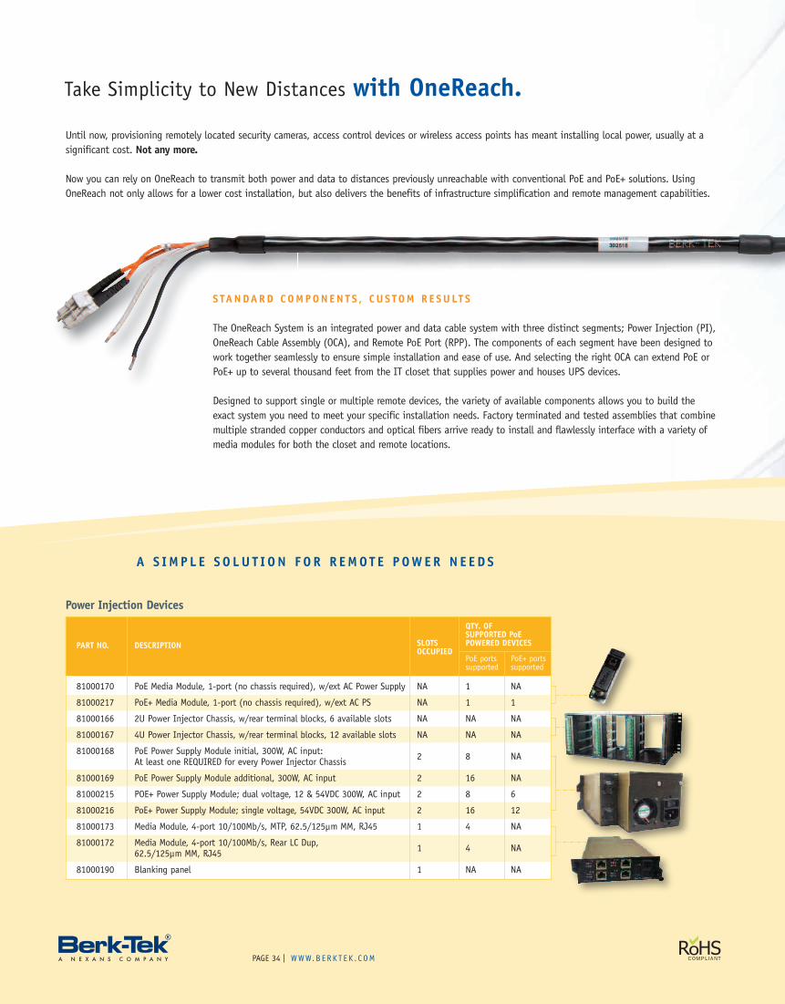
PAGE | WWW.B ERK T E K . C OM34
A S IM P L E S O LU T I ON F O R R EMOT E P OWER N E E D S
Take Simplicity to New Distances with OneReach.
STANDARD COMPONEN T S , CU S TOM R E SU LT S
The OneReach System is an integrated power and data cable system with three distinct segments; Power Injection (PI),OneReach Cable Assembly (OCA), and Remote PoE Port (RPP). The components of each segment have been designed towork together seamlessly to ensure simple installation and ease of use. And selecting the right OCA can extend PoE orPoE+ up to several thousand feet from the IT closet that supplies power and houses UPS devices.
Designed to support single or multiple remote devices, the variety of available components allows you to build theexact system you need to meet your specific installation needs. Factory terminated and tested assemblies that combinemultiple stranded copper conductors and optical fibers arrive ready to install and flawlessly interface with a variety ofmedia modules for both the closet and remote locations.
Until now, provisioning remotely located security cameras, access control devices or wireless access points has meant installing local power, usually at asignificant cost. Not any more.
Now you can rely on OneReach to transmit both power and data to distances previously unreachable with conventional PoE and PoE+ solutions. UsingOneReach not only allows for a lower cost installation, but also delivers the benefits of infrastructure simplification and remote management capabilities.
Power Injection Devices
PART NO. DESCRIPTION
QTY. OF
SLOTSSUPPORTED PoE
OCCUPIEDPOWERED DEVICES
PoE ports PoE+ portssupported supported
81000170 PoE Media Module, 1-port (no chassis required), w/ext AC Power Supply NA 1 NA
81000217 PoE+ Media Module, 1-port (no chassis required), w/ext AC PS NA 1 1
81000166 2U Power Injector Chassis, w/rear terminal blocks, 6 available slots NA NA NA
81000167 4U Power Injector Chassis, w/rear terminal blocks, 12 available slots NA NA NA
81000168 PoE Power Supply Module initial, 300W, AC input: 2 8 NAAt least one REQUIRED for every Power Injector Chassis
81000169 PoE Power Supply Module additional, 300W, AC input 2 16 NA
81000215 POE+ Power Supply Module; dual voltage, 12 & 54VDC 300W, AC input 2 8 6
81000216 PoE+ Power Supply Module; single voltage, 54VDC 300W, AC input 2 16 12
81000173 Media Module, 4-port 10/100Mb/s, MTP, 62.5/125µm MM, RJ45 1 4 NA
81000172 Media Module, 4-port 10/100Mb/s, Rear LC Dup,62.5/125µm MM, RJ45 1 4 NA
81000190 Blanking panel 1 NA NA
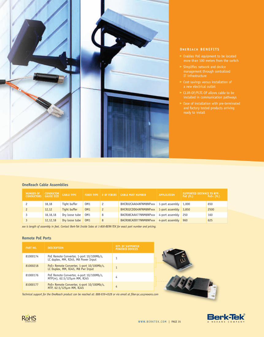
WWW.B ERK T E K . C OM | PAGE 35
ON ER E A C H B EN E F I T S
� Enables PoE equipment to be locatedmore than 100 meters from the switch
� Simplifies network and devicemanagement through centralizedIT infrastructure
� Cost savings versus installation ofa new electrical outlet
� CL3R-OF/PLTC-OF allows cable to beinstalled in communication pathways
� Ease of installation with pre-terminatedand factory tested products arrivingready to install
OneReach Cable Assemblies
NUMBER OF CONDUCTOR CABLE TYPE FIBER TYPE # OF FIBERS CABLE PART NUMBER APPLICATION SUPPORTED DISTANCE TO RPP:CONDUCTORS GAUGE SIZE PoE (ft.) PoE+ (ft.)
2 18,18 Tight buffer OM1 2 BHCR02CAA04NFNM8NPxxx 1-port assembly 1,000 650
2 12,12 Tight buffer OM1 2 BHCR02CDD04NFNM8NPxxx 1-port assembly 3,850 2500
3 18,18,18 Dry loose tube OM1 8 BACR08CAAA77NNM8NPxxx 4-port assembly 250 160
3 12,12,18 Dry loose tube OM1 8 BACR08CADD77NNM8NPxxx 4-port assembly 960 625
xxx is length of assembly in feet. Contact Berk-Tek Inside Sales at 1-800-BERK-TEK for exact part number and pricing.
Remote PoE Ports
PART NO. DESCRIPTION QTY. OF SUPPORTEDPOWERED DEVICES
81000174 PoE Remote Converter, 1-port 10/100Mb/s, 1LC duplex, MM, RJ45, M8 Power Input
81000218 PoE+ Remote Converter, 1-port 10/100Mb/s, 1LC Duplex, MM, RJ45, M8 Pwr Input
81000176 PoE Remote Converter, 4-port 10/100Mb/s, 4MTP(m), 62.5/125µm MM, RJ45
81000177 PoE+ Remote Converter, 4-port 10/100Mb/s, 4MTP, 62.5/125µm MM, RJ45
Technical support for the OneReach product can be reached at: 888-939-4528 or via email at [email protected]
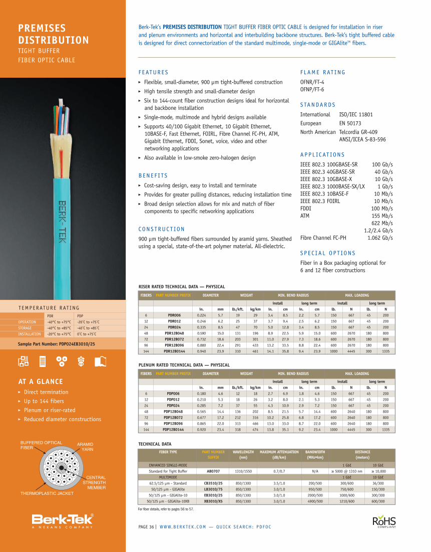
PAGE | WWW.B ERK T E K . C OM — QUICK S EAR CH : PD FO C36
F E ATUR E S� Flexible, small-diameter, 900 µm tight-buffered construction� High tensile strength and small-diameter design� Six to 144-count fiber construction designs ideal for horizontaland backbone installation
� Single-mode, multimode and hybrid designs available� Supports 40/100 Gigabit Ethernet, 10 Gigabit Ethernet,10BASE-F, Fast Ethernet, FOIRL, Fibre Channel FC-PH, ATM,Gigabit Ethernet, FDDI, Sonet, voice, video and othernetworking applications
� Also available in low-smoke zero-halogen design
B EN E F I TS� Cost-saving design, easy to install and terminate� Provides for greater pulling distances, reducing installation time� Broad design selection allows for mix and match of fibercomponents to specific networking applications
CONS T RUC T ION
900 µm tight-buffered fibers surrounded by aramid yarns. Sheathedusing a special, state-of-the-art polymer material. All-dielectric.
F L AME RAT ING
OFNR/FT-4OFNP/FT-6
S TANDARDS
International ISO/IEC 11801European EN 50173North American Telcordia GR-409
ANSI/ICEA S-83-596
APP L IC AT ION S
IEEE 802.3 100GBASE-SR 100 Gb/sIEEE 802.3 40GBASE-SR 40 Gb/sIEEE 802.3 10GBASE-X 10 Gb/sIEEE 802.3 1000BASE-SX/LX 1 Gb/sIEEE 802.3 10BASE-F 10 Mb/sIEEE 802.3 FOIRL 10 Mb/sFDDI 100 Mb/sATM 155 Mb/s
622 Mb/s1.2/2.4 Gb/s
Fibre Channel FC-PH 1.062 Gb/s
S P E C I A L OP T ION S
Fiber in a Box packaging optional for6 and 12 fiber constructions
T EMP ERATUR E RAT INGPDR PDP
-40°C to +75°C -20˚C to +75˚C
-40°C to +85°C -40˚C to +85˚C
-20°C to +75°C 0˚C to +75˚C
OPERATION
STORAGE
INSTALLATION
AT A GLANCE� Direct termination� Up to 144 fibers� Plenum or riser-rated� Reduced diameter constructions
Berk-Tek’s PREMISES DISTRIBUTION TIGHT BUFFER FIBER OPTIC CABLE is designed for installation in riserand plenum environments and horizontal and interbuilding backbone structures. Berk-Tek’s tight buffered cableis designed for direct connectorization of the standard multimode, single-mode or GIGAliteTM fibers.
PREMISESDISTRIBUTIONTIGHT BUFFERFIBER OPTIC CABLE
PLENUM RATED TECHNICAL DATA — PHYSICAL
FIBERS PART NUMBER PREFIX DIAMETER WEIGHT MIN. BEND RADIUS MAX. LOADING
install long term install long termin. mm lb./kft. kg/km in. cm in. cm lb. N lb. N
6 PDP006 0.180 4.6 12 18 2.7 6.9 1.8 4.6 150 667 45 200
12 PDP012 0.210 5.3 18 26 3.2 8.0 2.1 5.3 150 667 45 200
24 PDP024 0.285 7.2 37 55 4.3 10.9 2.9 7.2 150 667 45 200
48 PDP12B048 0.565 14.4 136 202 8.5 21.5 5.7 14.4 600 2640 180 800
72 PDP12B072 0.677 17.2 212 316 10.2 25.8 6.8 17.2 600 2640 180 800
96 PDP12B096 0.865 22.0 313 466 13.0 33.0 8.7 22.0 600 2640 180 800
144 PDP12B0144 0.920 23.4 318 474 13.8 35.1 9.2 23.4 1000 4445 300 1335
For fiber details, refer to pages 56 to 57.
Sample Part Number: PDP024EB3010/25
TECHNICAL DATA
FIBER TYPE PART NUMBER WAVELENGTH MAXIMUM ATTENUATION BANDWIDTH DISTANCESUFFIX (nm) (dB/km) (MHz•km) (meters)
ENHANCED SINGLE-MODE 1 GbE 10 GbE
Standard for Tight Buffer AB0707 1310/1550 0.7/0.7 N/A ≥ 5000 @ 1310 nm ≥ 10,000
MULTIMODE 1 GbE 10 GbE
62.5/125 µm - Standard CB3510/25 850/1300 3.5/1.0 200/500 300/600 36/300
50/125 µm - GIGAlite LB3010/75 850/1300 3.0/1.0 950/500 750/600 150/300
50/125 µm - GIGAlite-10 EB3010/25 850/1300 3.0/1.0 2000/500 1000/600 300/300
50/125 µm - GIGAlite-10XB XB3010/X5 850/1300 3.0/1.0 4900/500 1210/600 600/300
RISER RATED TECHNICAL DATA — PHYSICAL
FIBERS PART NUMBER PREFIX DIAMETER WEIGHT MIN. BEND RADIUS MAX. LOADING
install long term install long termin. mm lb./kft. kg/km in. cm in. cm lb. N lb. N
6 PDR006 0.224 5.7 19 29 3.4 8.5 2.2 5.7 150 667 45 200
12 PDR012 0.246 6.2 25 37 3.7 9.4 2.5 6.2 150 667 45 200
24 PDR024 0.335 8.5 47 70 5.0 12.8 3.4 8.5 150 667 45 200
48 PDR12B048 0.590 15.0 131 196 8.9 22.5 5.9 15.0 600 2670 180 800
72 PDR12B072 0.732 18.6 203 301 11.0 27.9 7.3 18.6 600 2670 180 800
96 PDR12B096 0.880 22.4 291 433 13.2 33.5 8.8 22.4 600 2670 180 800
144 PDR12B0144 0.940 23.9 310 461 14.1 35.8 9.4 23.9 1000 4445 300 1335
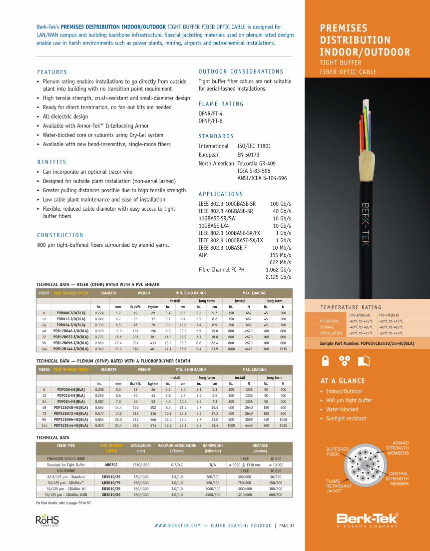
WWW.B ERK T E K . C OM — QUICK S EAR CH : PD IO FO C | PAGE 37
F E ATUR E S� Plenum rating enables installations to go directly from outsideplant into building with no transition point requirement
� High tensile strength, crush-resistant and small-diameter design� Ready for direct termination, no fan out kits are needed� All-dielectric design� Available with Armor-Tek™ Interlocking Armor� Water-blocked core or subunits using Dry-Gel system� Available with new bend-insensitive, single-mode fibers
B EN E F I TS� Can incorporate an optional tracer wire� Designed for outside plant installation (non-aerial lashed)� Greater pulling distances possible due to high tensile strength� Low cable plant maintenance and ease of installation� Flexible, reduced cable diameter with easy access to tightbuffer fibers
C ON S T RUC T ION
900 µm tight-buffered fibers surrounded by aramid yarns.
T EMP ERATUR E RAT INGPDR-I/O(BLA) PDP-HE(BLA)
-40°C to +75°C -20°C to +75°C
-40°C to +85°C -40°C to +85°C
-20°C to +75°C -20°C to +75°C
OPERATION
STORAGE
INSTALLATION
AT A GLANCE� Indoor/Outdoor� 900 µm tight buffer� Water-blocked� Sunlight resistant
Berk-Tek’s PREMISES DISTRIBUTION INDOOR/OUTDOOR TIGHT BUFFER FIBER OPTIC CABLE is designed forLAN/WAN campus and building backbone infrastructure. Special jacketing materials used on plenum rated designsenable use in harsh environments such as power plants, mining, airports and petrochemical installations.
PREMISESDISTRIBUTIONINDOOR/OUTDOORTIGHT BUFFERFIBER OPTIC CABLE
Sample Part Number: PDP024CB3510/25-HE(BLA)
TECHNICAL DATA — RISER (OFNR) RATED WITH A PVC SHEATH
FIBERS PART NUMBER PREFIX DIAMETER WEIGHT MIN. BEND RADIUS MAX. LOADING
install long term install long termin. mm lb./kft. kg/km in. cm in. cm lb. N lb. N
6 PDR006-I/O(BLA) 0.224 5.7 19 29 3.4 8.5 2.2 5.7 150 667 45 200
12 PDR012-I/O(BLA) 0.246 6.2 25 37 3.7 9.4 2.5 6.2 150 667 45 200
24 PDR024-I/O(BLA) 0.335 8.5 47 70 5.0 12.8 3.4 8.5 150 667 45 200
48 PDR12B048-I/O(BLA) 0.590 15.0 131 196 8.9 22.5 5.9 15.0 600 2670 180 800
72 PDR12B072-I/O(BLA) 0.732 18.6 203 301 11.0 27.9 7.3 18.6 600 2670 180 800
96 PDR12B096-I/O(BLA) 0.880 22.4 291 433 13.2 33.5 8.8 22.4 600 2670 180 800
144 PDR12B144-I/O(BLA) 0.940 23.9 310 461 14.1 35.8 9.4 23.9 1000 4445 300 1335
For fiber details, refer to pages 56 to 57.
TECHNICAL DATA
FIBER TYPE PART NUMBER WAVELENGTH MAXIMUM ATTENUATION BANDWIDTH DISTANCESUFFIX (nm) (dB/km) (MHz•km) (meters)
ENHANCED SINGLE-MODE 1 GbE 10 GbE
Standard for Tight Buffer AB0707 1310/1550 0.7/0.7 N/A ≥ 5000 @ 1310 nm ≥ 10,000
MULTIMODE 1 GbE 10 GbE
62.5/125 µm - Standard CB3510/25 850/1300 3.5/1.0 200/500 300/600 36/300
50/125 µm - GIGAlite™ LB3010/75 850/1300 3.0/1.0 950/500 750/600 150/300
50/125 µm - GIGAlite-10 EB3010/25 850/1300 3.0/1.0 2000/500 1000/600 300/300
50/125 µm - GIGAlite-10XB XB3010/X5 850/1300 3.0/1.0 4900/500 1210/600 600/300
TECHNICAL DATA — PLENUM (OFNP) RATED WITH A FLUOROPOLYMER SHEATH
FIBERS PART NUMBER PREFIX DIAMETER WEIGHT MIN. BEND RADIUS MAX. LOADING
install long term install long termin. mm lb./kft. kg/km in. cm in. cm lb. N lb. N
6 PDP006-HE(BLA) 0.208 5.3 18 26 3.1 7.9 2.1 5.3 300 1335 90 400
12 PDP012-HE(BLA) 0.255 6.5 30 44 3.8 9.7 2.6 6.5 300 1335 90 400
24 PDP024-HE(BLA) 0.287 7.3 36 53 4.3 10.9 2.9 7.3 300 1335 90 400
48 PDP12B048-HE(BLA) 0.565 14.4 136 202 8.5 21.5 5.7 14.4 600 2640 180 800
72 PDP12B072-HE(BLA) 0.677 17.2 212 316 10.2 25.8 6.8 17.2 600 2640 180 800
96 PDP12B096-HE(BLA) 0.865 22.0 313 466 13.0 33.0 8.7 22.0 800 3559 240 1068
144 PDP12B144-HE(BLA) 0.920 23.4 318 474 13.8 35.1 9.2 23.4 1000 4445 300 1335
OU TDOOR CONS I D E RAT ION S
Tight buffer fiber cables are not suitablefor aerial-lashed installations.
F L AME RAT ING
OFNR/FT-4OFNP/FT-6
S TANDARDS
International ISO/IEC 11801European EN 50173North American Telcordia GR-409
ICEA S-83-596ANSI/ICEA S-104-696
APP L IC AT ION S
IEEE 802.3 100GBASE-SR 100 Gb/sIEEE 802.3 40GBASE-SR 40 Gb/s10GBASE-SR/SW 10 Gb/s10GBASE-LX4 10 Gb/sIEEE 802.3 100BASE-SX/FX 1 Gb/sIEEE 802.3 1000BASE-SX/LX 1 Gb/sIEEE 802.3 10BASE-F 10 Mb/sATM 155 Mb/s
622 Mb/sFibre Channel FC-PH 1.062 Gb/s
2.125 Gb/s
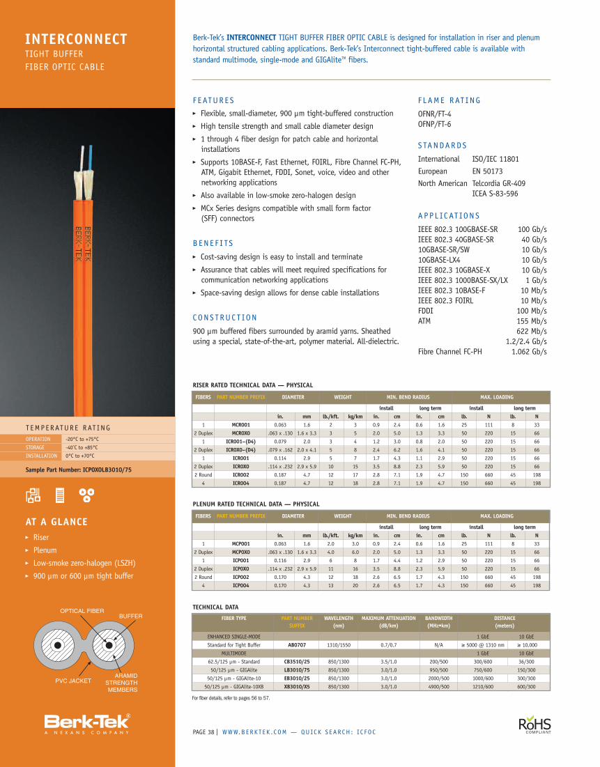
PAGE | WWW.B ERK T E K . C OM — QUICK S EAR CH : I C F O C38
F E ATUR E S� Flexible, small-diameter, 900 µm tight-buffered construction� High tensile strength and small cable diameter design� 1 through 4 fiber design for patch cable and horizontalinstallations
� Supports 10BASE-F, Fast Ethernet, FOIRL, Fibre Channel FC-PH,ATM, Gigabit Ethernet, FDDI, Sonet, voice, video and othernetworking applications
� Also available in low-smoke zero-halogen design� MCx Series designs compatible with small form factor(SFF) connectors
B EN E F I TS� Cost-saving design is easy to install and terminate� Assurance that cables will meet required specifications forcommunication networking applications
� Space-saving design allows for dense cable installations
CONS T RUC T ION
900 µm buffered fibers surrounded by aramid yarns. Sheathedusing a special, state-of-the-art, polymer material. All-dielectric.
F L AME RAT ING
OFNR/FT-4OFNP/FT-6
S TANDARDS
International ISO/IEC 11801European EN 50173North American Telcordia GR-409
ICEA S-83-596
APP L IC AT ION S
IEEE 802.3 100GBASE-SR 100 Gb/sIEEE 802.3 40GBASE-SR 40 Gb/s10GBASE-SR/SW 10 Gb/s10GBASE-LX4 10 Gb/sIEEE 802.3 10GBASE-X 10 Gb/sIEEE 802.3 1000BASE-SX/LX 1 Gb/sIEEE 802.3 10BASE-F 10 Mb/sIEEE 802.3 FOIRL 10 Mb/sFDDI 100 Mb/sATM 155 Mb/s
622 Mb/s1.2/2.4 Gb/s
Fibre Channel FC-PH 1.062 Gb/s
T EMP ERATUR E RAT ING-20°C to +75°C
-40˚C to +85°C
0°C to +70°C
OPERATION
STORAGE
INSTALLATION
AT A GLANCE� Riser� Plenum� Low-smoke zero-halogen (LSZH)� 900 µm or 600 µm tight buffer
Berk-Tek’s INTERCONNECT TIGHT BUFFER FIBER OPTIC CABLE is designed for installation in riser and plenumhorizontal structured cabling applications. Berk-Tek’s Interconnect tight-buffered cable is available withstandard multimode, single-mode and GIGAliteTM fibers.
INTERCONNECTTIGHT BUFFERFIBER OPTIC CABLE
RISER RATED TECHNICAL DATA — PHYSICAL
FIBERS PART NUMBER PREFIX DIAMETER WEIGHT MIN. BEND RADIUS MAX. LOADING
install long term install long termin. mm lb./kft. kg/km in. cm in. cm lb. N lb. N
1 MCR001 0.063 1.6 2 3 0.9 2.4 0.6 1.6 25 111 8 33
2 Duplex MCR0X0 .063 x .130 1.6 x 3.3 3 5 2.0 5.0 1.3 3.3 50 220 15 66
1 ICR001–(D4) 0.079 2.0 3 4 1.2 3.0 0.8 2.0 50 220 15 66
2 Duplex ICR0X0–(D4) .079 x .162 2.0 x 4.1 5 8 2.4 6.2 1.6 4.1 50 220 15 66
1 ICR001 0.114 2.9 5 7 1.7 4.3 1.1 2.9 50 220 15 66
2 Duplex ICR0X0 .114 x .232 2.9 x 5.9 10 15 3.5 8.8 2.3 5.9 50 220 15 66
2 Round ICR002 0.187 4.7 12 17 2.8 7.1 1.9 4.7 150 660 45 198
4 ICR004 0.187 4.7 12 18 2.8 7.1 1.9 4.7 150 660 45 198
PLENUM RATED TECHNICAL DATA — PHYSICAL
FIBERS PART NUMBER PREFIX DIAMETER WEIGHT MIN. BEND RADIUS MAX. LOADING
install long term install long termin. mm lb./kft. kg/km in. cm in. cm lb. N lb. N
1 MCP001 0.063 1.6 2.0 3.0 0.9 2.4 0.6 1.6 25 111 8 33
2 Duplex MCP0X0 .063 x .130 1.6 x 3.3 4.0 6.0 2.0 5.0 1.3 3.3 50 220 15 66
1 ICP001 0.116 2.9 6 8 1.7 4.4 1.2 2.9 50 220 15 66
2 Duplex ICP0X0 .114 x .232 2.9 x 5.9 11 16 3.5 8.8 2.3 5.9 50 220 15 66
2 Round ICP002 0.170 4.3 12 18 2.6 6.5 1.7 4.3 150 660 45 198
4 ICP004 0.170 4.3 13 20 2.6 6.5 1.7 4.3 150 660 45 198
Sample Part Number: ICPOXOLB3010/75
For fiber details, refer to pages 56 to 57.
TECHNICAL DATA
FIBER TYPE PART NUMBER WAVELENGTH MAXIMUM ATTENUATION BANDWIDTH DISTANCESUFFIX (nm) (dB/km) (MHz•km) (meters)
ENHANCED SINGLE-MODE 1 GbE 10 GbE
Standard for Tight Buffer AB0707 1310/1550 0.7/0.7 N/A ≥ 5000 @ 1310 nm ≥ 10,000
MULTIMODE 1 GbE 10 GbE
62.5/125 µm - Standard CB3510/25 850/1300 3.5/1.0 200/500 300/600 36/300
50/125 µm - GIGAlite LB3010/75 850/1300 3.0/1.0 950/500 750/600 150/300
50/125 µm - GIGAlite-10 EB3010/25 850/1300 3.0/1.0 2000/500 1000/600 300/300
50/125 µm - GIGAlite-10XB XB3010/X5 850/1300 3.0/1.0 4900/500 1210/600 600/300
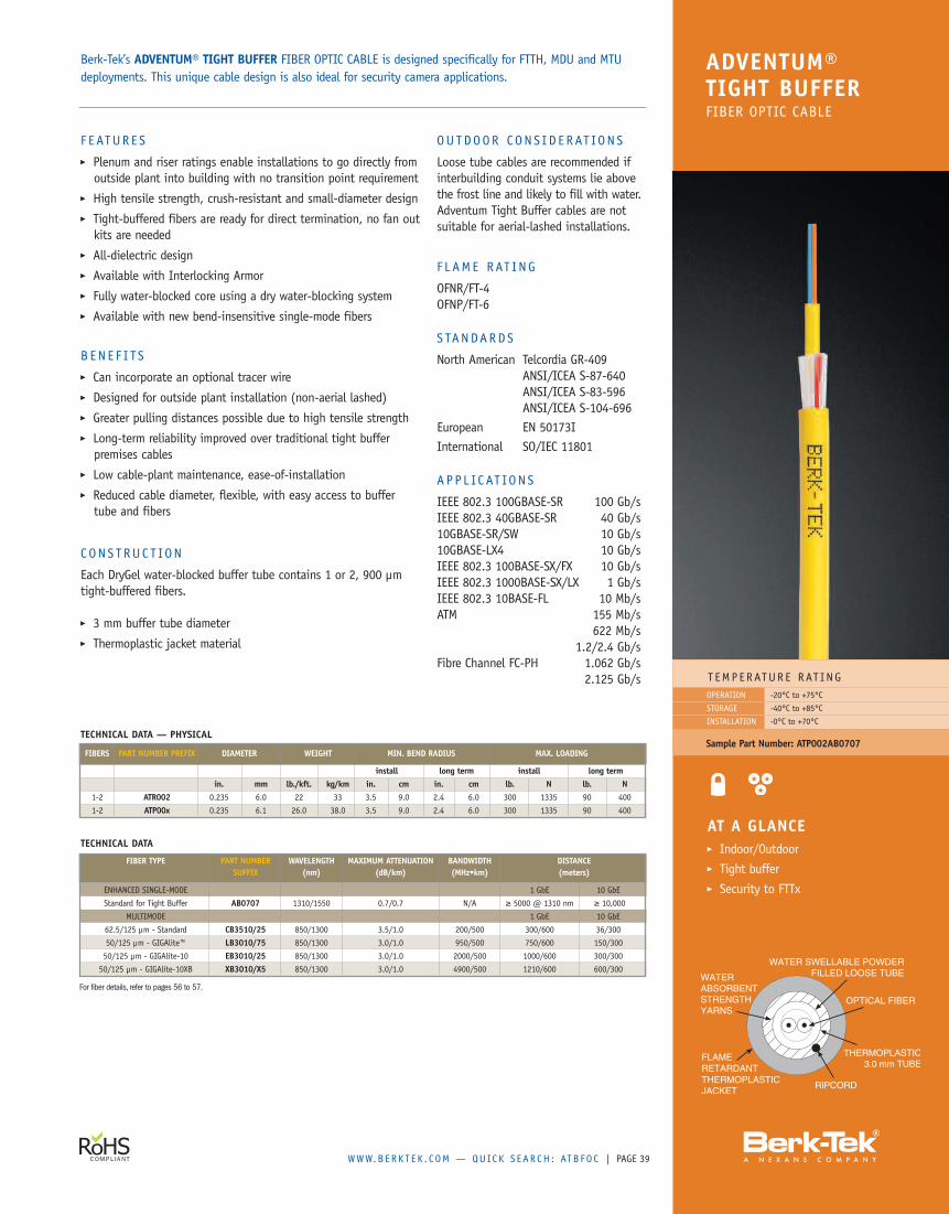
WWW.B ERK T E K . C OM — QUICK S EAR CH : ATB FO C | PAGE 39
ADVENTUM®TIGHT BUFFERFIBER OPTIC CABLE
F EATUR E S� Plenum and riser ratings enable installations to go directly fromoutside plant into building with no transition point requirement
� High tensile strength, crush-resistant and small-diameter design� Tight-buffered fibers are ready for direct termination, no fan outkits are needed
� All-dielectric design� Available with Interlocking Armor� Fully water-blocked core using a dry water-blocking system� Available with new bend-insensitive single-mode fibers
B EN E F I TS� Can incorporate an optional tracer wire� Designed for outside plant installation (non-aerial lashed)� Greater pulling distances possible due to high tensile strength� Long-term reliability improved over traditional tight bufferpremises cables
� Low cable-plant maintenance, ease-of-installation� Reduced cable diameter, flexible, with easy access to buffertube and fibers
C ON S T RUC T ION
Each DryGel water-blocked buffer tube contains 1 or 2, 900 µmtight-buffered fibers.
� 3 mm buffer tube diameter� Thermoplastic jacket material
OU TDOOR CONS I D E RAT ION S
Loose tube cables are recommended ifinterbuilding conduit systems lie abovethe frost line and likely to fill with water.Adventum Tight Buffer cables are notsuitable for aerial-lashed installations.
F L AME RAT ING
OFNR/FT-4OFNP/FT-6
S TANDARDS
North American Telcordia GR-409ANSI/ICEA S-87-640ANSI/ICEA S-83-596ANSI/ICEA S-104-696
European EN 50173IInternational SO/IEC 11801
APP L IC AT ION S
IEEE 802.3 100GBASE-SR 100 Gb/sIEEE 802.3 40GBASE-SR 40 Gb/s10GBASE-SR/SW 10 Gb/s10GBASE-LX4 10 Gb/sIEEE 802.3 100BASE-SX/FX 10 Gb/sIEEE 802.3 1000BASE-SX/LX 1 Gb/sIEEE 802.3 10BASE-FL 10 Mb/sATM 155 Mb/s
622 Mb/s1.2/2.4 Gb/s
Fibre Channel FC-PH 1.062 Gb/s2.125 Gb/s T EMP ERATUR E RAT ING
Berk-Tek’s ADVENTUM® TIGHT BUFFER FIBER OPTIC CABLE is designed specifically for FTTH, MDU and MTUdeployments. This unique cable design is also ideal for security camera applications.
-20°C to +75°C
-40°C to +85°C
-0°C to +70°C
OPERATION
STORAGE
INSTALLATION
Sample Part Number: ATP002AB0707
AT A GLANCE� Indoor/Outdoor� Tight buffer� Security to FTTx
TECHNICAL DATA — PHYSICAL
FIBERS PART NUMBER PREFIX DIAMETER WEIGHT MIN. BEND RADIUS MAX. LOADING
install long term install long termin. mm lb./kft. kg/km in. cm in. cm lb. N lb. N
1-2 ATR002 0.235 6.0 22 33 3.5 9.0 2.4 6.0 300 1335 90 400
1-2 ATP00x 0.235 6.1 26.0 38.0 3.5 9.0 2.4 6.0 300 1335 90 400
For fiber details, refer to pages 56 to 57.
TECHNICAL DATA
FIBER TYPE PART NUMBER WAVELENGTH MAXIMUM ATTENUATION BANDWIDTH DISTANCESUFFIX (nm) (dB/km) (MHz•km) (meters)
ENHANCED SINGLE-MODE 1 GbE 10 GbE
Standard for Tight Buffer AB0707 1310/1550 0.7/0.7 N/A ≥ 5000 @ 1310 nm ≥ 10,000
MULTIMODE 1 GbE 10 GbE
62.5/125 µm - Standard CB3510/25 850/1300 3.5/1.0 200/500 300/600 36/300
50/125 µm - GIGAlite™ LB3010/75 850/1300 3.0/1.0 950/500 750/600 150/300
50/125 µm - GIGAlite-10 EB3010/25 850/1300 3.0/1.0 2000/500 1000/600 300/300
50/125 µm - GIGAlite-10XB XB3010/X5 850/1300 3.0/1.0 4900/500 1210/600 600/300
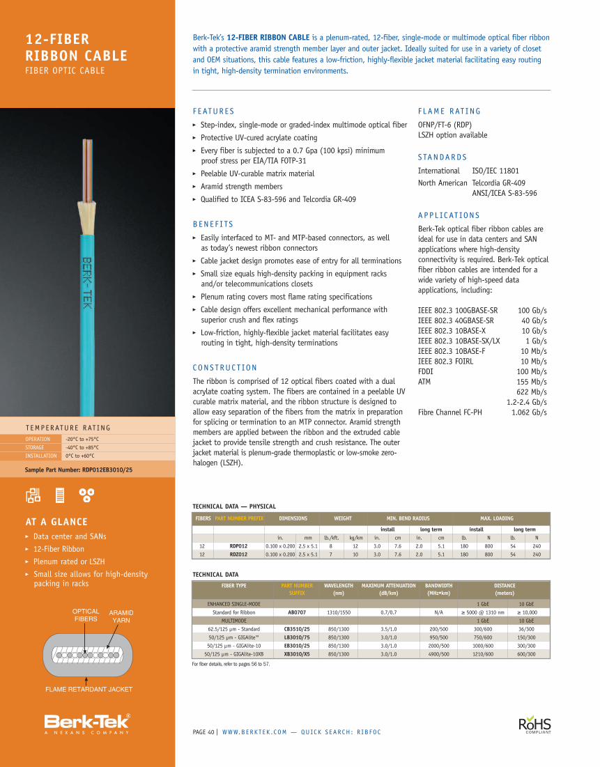
PAGE | WWW.B ERK T E K . C OM — QUICK S EAR CH : R I B FO C40
F E ATUR E S� Step-index, single-mode or graded-index multimode optical fiber� Protective UV-cured acrylate coating� Every fiber is subjected to a 0.7 Gpa (100 kpsi) minimumproof stress per EIA/TIA FOTP-31
� Peelable UV-curable matrix material� Aramid strength members� Qualified to ICEA S-83-596 and Telcordia GR-409
B EN E F I TS� Easily interfaced to MT- and MTP-based connectors, as wellas today’s newest ribbon connectors
� Cable jacket design promotes ease of entry for all terminations� Small size equals high-density packing in equipment racksand/or telecommunications closets
� Plenum rating covers most flame rating specifications� Cable design offers excellent mechanical performance withsuperior crush and flex ratings
� Low-friction, highly-flexible jacket material facilitates easyrouting in tight, high-density terminations
CONS T RUC T ION
The ribbon is comprised of 12 optical fibers coated with a dualacrylate coating system. The fibers are contained in a peelable UVcurable matrix material, and the ribbon structure is designed toallow easy separation of the fibers from the matrix in preparationfor splicing or termination to an MTP connector. Aramid strengthmembers are applied between the ribbon and the extruded cablejacket to provide tensile strength and crush resistance. The outerjacket material is plenum-grade thermoplastic or low-smoke zero-halogen (LSZH).
F L AME RAT ING
OFNP/FT-6 (RDP)LSZH option available
S TANDARDS
International ISO/IEC 11801North American Telcordia GR-409
ANSI/ICEA S-83-596
APP L IC AT ION S
Berk-Tek optical fiber ribbon cables areideal for use in data centers and SANapplications where high-densityconnectivity is required. Berk-Tek opticalfiber ribbon cables are intended for awide variety of high-speed dataapplications, including:
IEEE 802.3 100GBASE-SR 100 Gb/sIEEE 802.3 40GBASE-SR 40 Gb/sIEEE 802.3 10BASE-X 10 Gb/sIEEE 802.3 10BASE-SX/LX 1 Gb/sIEEE 802.3 10BASE-F 10 Mb/sIEEE 802.3 FOIRL 10 Mb/sFDDI 100 Mb/sATM 155 Mb/s
622 Mb/s1.2-2.4 Gb/s
Fibre Channel FC-PH 1.062 Gb/s
Berk-Tek’s 12-FIBER RIBBON CABLE is a plenum-rated, 12-fiber, single-mode or multimode optical fiber ribbonwith a protective aramid strength member layer and outer jacket. Ideally suited for use in a variety of closetand OEM situations, this cable features a low-friction, highly-flexible jacket material facilitating easy routingin tight, high-density termination environments.
12-FIBERRIBBON CABLEFIBER OPTIC CABLE
T EMPERATUR E RAT INGOPERATION
STORAGE
INSTALLATION
-20°C to +75°C
-40°C to +85°C
0°C to +60°C
AT A GLANCE� Data center and SANs� 12-Fiber Ribbon� Plenum rated or LSZH� Small size allows for high-densitypacking in racks
Sample Part Number: RDP012EB3010/25
TECHNICAL DATA — PHYSICAL
FIBERS PART NUMBER PREFIX DIMENSIONS WEIGHT MIN. BEND RADIUS MAX. LOADING
install long term install long termin. mm lb./kft. kg/km in. cm in. cm lb. N lb. N
12 RDP012 0.100 x 0.200 2.5 x 5.1 8 12 3.0 7.6 2.0 5.1 180 800 54 240
12 RDZ012 0.100 x 0.200 2.5 x 5.1 7 10 3.0 7.6 2.0 5.1 180 800 54 240
TECHNICAL DATA
FIBER TYPE PART NUMBER WAVELENGTH MAXIMUM ATTENUATION BANDWIDTH DISTANCESUFFIX (nm) (dB/km) (MHz•km) (meters)
ENHANCED SINGLE-MODE 1 GbE 10 GbE
Standard for Ribbon AB0707 1310/1550 0.7/0.7 N/A ≥ 5000 @ 1310 nm ≥ 10,000
MULTIMODE 1 GbE 10 GbE
62.5/125 µm - Standard CB3510/25 850/1300 3.5/1.0 200/500 300/600 36/300
50/125 µm - GIGAlite™ LB3010/75 850/1300 3.0/1.0 950/500 750/600 150/300
50/125 µm - GIGAlite-10 EB3010/25 850/1300 3.0/1.0 2000/500 1000/600 300/300
50/125 µm - GIGAlite-10XB XB3010/X5 850/1300 3.0/1.0 4900/500 1210/600 600/300
For fiber details, refer to pages 56 to 57.
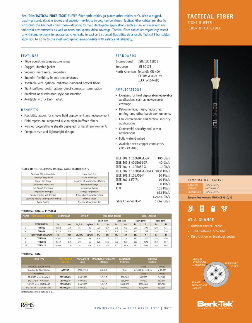
WWW.B ERK T E K . C OM — QUICK S EAR CH : T F F O C | PAGE
Berk-Tek's TACTICAL FIBER TIGHT BUFFER fiber optic cables go places other cables can’t. With a rugged,crush-resistant, durable jacket and superior flexibility in cold temperatures, Tactical Fiber cables are able towithstand the harshest conditions—allowing for field deployable applications such as law enforcement andindustrial environments as well as news and sports video coverage. Tactical Fiber cables are vigorously testedto withstand extreme temperatures, chemicals, impact and stressed flexibility. As a result, Tactical Fiber cablesallow you to go in to the most unforgiving environments with safety and reliability.
TACTICAL FIBERTIGHT BUFFERFIBER OPTIC CABLE
41
T EMP ERATUR E RAT ING-46°C to +71°C
-55°C to +85°C
-46°C to +71°C
OPERATION
STORAGE
INSTALLATION
Sample Part Number: TFC004CB3510/25
AT A GLANCE� Outdoor tactical cable� Tight buffered 2-24 fiber� Distribution or breakout design
F EATUR E S� Wide operating temperature range� Rugged, durable jacket� Superior mechanical properties� Superior flexibility in cold temperatures� Available with optional radiation-hardened optical fibers� Tight-buffered design allows direct connector termination� Breakout or distribution style construction� Available with a LSZH jacket
B EN E F I TS� Flexibility allows for simple field deployment and redeployment� Field repairs are supported due to tight-buffered fibers� Rugged polyurethane sheath designed for harsh environments� Compact size and lightweight design
S TANDARDS
International ISO/IEC 11801European EN 50173North American Telcordia GR-409
CECOM A3159879ICEA S-104-696
APP L IC AT ION S� Excellent for field deployable/retrievableapplications such as news/sportscoverage
� Petrochemical, heavy industrial,mining, and other harsh environments
� Law enforcement and tactical securityapplications
� Commercial security and sensorapplications
� Fully water-blocked� Available with copper conductors(12 - 24 AWG)
IEEE 802.3 100GBASE-SR 100 Gb/sIEEE 802.3 40GBASE-SR 40 Gb/sIEEE 802.3 10GBASE-X 10 Gb/sIEEE 802.3 1000BASE-SX/LX 1000 Mb/sIEEE 802.3 10BASE-F 10 Mb/sIEEE 802.3 FOIRL 10 Mb/sFDDI 100 Mb/sATM 155 Mb/s
622 Mb/s1.2/2.4 Gb/s
Fibre Channel FC-PH 1.062 Gb/s
TESTED TO THE FOLLOWING TACTICAL CABLE REQUIREMENTS
Maximum Attenuation Rate Cable Knot Test
Low/High Temp Bend Cable Shrinkage
Impact Resistance Durability of Identification Marking
Cold Impact Resistance Temperature Range
Hot Impact Resistance Temperature Cycling
Compressive Strength Storage Temperature
Tensile Loading and Bending Temperature/Humidity Cycling
Operating Tensile Loading and Bending Thermal Shock
Cyclic Flexing Freezing Water Immersion
TECHNICAL DATA — PHYSICAL
FIBERS PART NUMBER PREFIX DIMENSIONS WEIGHT MIN. BEND RADIUS MAX. LOADING
short term long term short term long termDISTRIBUTION in. mm lb./kft. kg/km in. cm in. cm lb. N lb. N
2 TFC002 0.228 5.8 16 24 3.4 8.7 2.3 5.8 400 1779 120 534
4 TFC004 0.228 5.8 17 25 3.4 8.7 2.3 5.8 400 1779 120 534
HEAVY DUTY BREAKOUT in. mm lb./kft. kg/km in. cm in. cm lb. N lb. N4 TFHD004 0.301 7.6 26 39 4.5 11.5 3.0 7.6 490 2200 120 550
6 TFHD006 0.349 8.9 30 45 5.2 13.3 3.5 8.9 600 2670 150 667
12 TFHD012 0.504 12.8 78 116 7.6 19.2 5.0 12.8 750 3336 190 845
TECHNICAL DATA
FIBER TYPE PART NUMBER WAVELENGTH MAXIMUM ATTENUATION BANDWIDTH DISTANCESUFFIX (nm) (dB/km) (MHz•km) (meters)
ENHANCED SINGLE-MODE 1 GbE 10 GbE
Standard for Tight Buffer AB0707 1310/1550 0.7/0.7 N/A ≥ 5000 @ 1310 nm ≥ 10,000
MULTIMODE 1 GbE 10 GbE
62.5/125 µm - Standard CB3510/25 850/1300 3.5/1.0 200/500 300/600 36/300
50/125 µm - GIGAlite™ LB3010/75 850/1300 3.0/1.0 950/500 750/600 150/300
50/125 µm - GIGAlite-10 EB3010/25 850/1300 3.0/1.0 2000/500 1000/600 300/300
50/125 µm - GIGAlite-10XB XB3010/X5 850/1300 3.0/1.0 4900/500 1210/600 600/300
For fiber details, refer to pages 56 to 57.
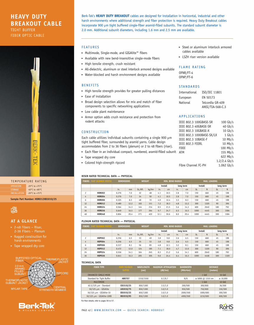
PAGE | WWW.B ERK T E K . C OM — QUICK S EAR CH : HDBROUT42
F E ATUR E S� Multimode, Single-mode, and GIGAlite™ fibers� Available with new bend-insensitive single-mode fibers� High tensile strength, crush resistant� All-dielectric, aluminum or steel interlock armored designs available� Water-blocked and harsh environment designs available
B EN E F I TS� High tensile strength provides for greater pulling distances� Ease of installation� Broad design selection allows for mix and match of fibercomponents to specific networking applications
� Low cable plant maintenance� Armor option adds crush resistance and protection fromrodent attacks
C ON S T RUC T ION
Each cable utilizes individual subunits containing a single 900 µmtight buffered fiber, surrounded by aramid yarns. Cable designaccommodates from 2 to 36 fibers (plenum) or 2 to 48 fibers (riser).� Each fiber in an individual compact, numbered, aramid-filled subunit� Tape wrapped dry core� Colored high-strength ripcord
� Steel or aluminum interlock armoredcables available
� LSZH riser version available
F L AME RAT ING
OFNR/FT-4OFNP/FT-6
S TANDARDS
International ISO/IEC 11801European EN 50173National Telcordia GR-409
ANSI/TIA-568-C.3
A P P L IC AT ION S
IEEE 802.3 100GBASE-SR 100 Gb/sIEEE 802.3 40GBASE-SR 40 Gb/sIEEE 802.3 10GBASE-X 10 Gb/sIEEE 802.3 1000BASE-SX/LX 1 Gb/sIEEE 802.3 10BASE-F 10 Mb/sIEEE 802.3 FOIRL 10 Mb/sFDDI 100 Mb/sATM 155 Mb/s
622 Mb/s1.2/2.4 Gb/s
Fibre Channel FC-PH 1.062 Gb/s
Berk-Tek’s HEAVY DUTY BREAKOUT cables are designed for installation in horizontal, industrial and otherharsh environments where additional strength and fiber protection is required. Heavy Duty Breakout cablesincorporate 900 µm tight buffered single-fiber aramid-filled subunits. The standard subunit diameter is2.0 mm. Additional subunit diameters, including 1.6 mm and 2.5 mm are available.
HEAVY DUTYBREAKOUT CABLETIGHT BUFFERFIBER OPTIC CABLE
T EMPERATUR E RAT INGOPERATION
STORAGE
INSTALLATION
-20°C to +75°C
-40°C to +85°C
-20°C to +75°C
AT A GLANCE� 2-48 Fibers – Riser,2-36 Fibers – Plenum
� Rugged construction forharsh environments
� Tape wrapped dry core
Sample Part Number: HDR012XB3010/25
RISER RATED TECHNICAL DATA — PHYSICAL
FIBERS PART NUMBER PREFIX DIMENSIONS WEIGHT MIN. BEND RADIUS MAX. LOADING
install long term install long termin. mm lb./kft. kg/km in. cm in. cm lb. N lb. N
2 HDR002 0.276 7.0 32 48 4.1 10.5 2.8 7.0 150 660 45 198
4 HDR004 0.276 7.0 34 50 4.1 10.5 2.8 7.0 150 660 45 198
6 HDR006 0.325 8.3 48 72 4.9 12.4 3.3 8.3 150 660 45 198
12 HDR012 0.480 12.2 102 151 7.2 18.3 4.8 12.2 300 1320 90 396
24 HDR024 0.564 14.3 144 214 8.5 21.5 5.6 14.3 600 2640 180 792
36 HDR036 0.649 16.5 177 264 9.7 24.7 6.5 16.5 1000 4445 300 1584
48 HDR048 0.804 20.4 271 403 12.1 30.6 8.0 20.4 1000 4445 300 1584
PLENUM RATED TECHNICAL DATA — PHYSICAL
FIBERS PART NUMBER PREFIX DIMENSIONS WEIGHT MIN. BEND RADIUS MAX. LOADING
install long term install long termin. mm lb./kft. kg/km in. cm in. cm lb. N lb. N
2 HDP002 0.256 6.5 33 49 3.8 9.8 2.6 6.5 150 660 45 198
4 HDP004 0.256 6.5 35 53 3.8 9.8 2.6 6.5 150 660 45 198
6 HDP006 0.317 8.1 56 83 4.8 12.1 3.2 8.1 150 660 45 198
12 HDP012 0.472 12.0 124 185 7.1 18.0 4.7 12.0 300 1320 90 396
24 HDP024 0.556 14.1 164 245 8.3 21.2 5.6 14.1 600 2640 180 792
36 HDP036 0.641 16.3 205 305 9.6 24.4 6.4 16.3 1000 4448 300 1320
For fiber details, refer to pages 56 to 57.
TECHNICAL DATA
FIBER TYPE PART NUMBER WAVELENGTH MAXIMUM ATTENUATION BANDWIDTH DISTANCESUFFIX (nm) (dB/km) (MHz•km) (meters)
ENHANCED SINGLE-MODE 1 GbE 10 GbE
Standard for Tight Buffer AB0707 1310/1550 0.7/0.7 N/A ≥ 5000 @ 1310 nm ≥ 10,000
MULTIMODE 1 GbE 10 GbE
62.5/125 µm - Standard CB3510/25 850/1300 3.5/1.0 200/500 300/600 36/300
50/125 µm - GIGAlite LB3010/75 850/1300 3.0/1.0 950/500 750/600 150/300
50/125 µm - GIGAlite-10 EB3010/25 850/1300 3.0/1.0 2000/500 1000/600 300/300
50/125 µm - GIGAlite-10XB XB3010/X5 850/1300 3.0/1.0 4900/500 1210/600 600/300
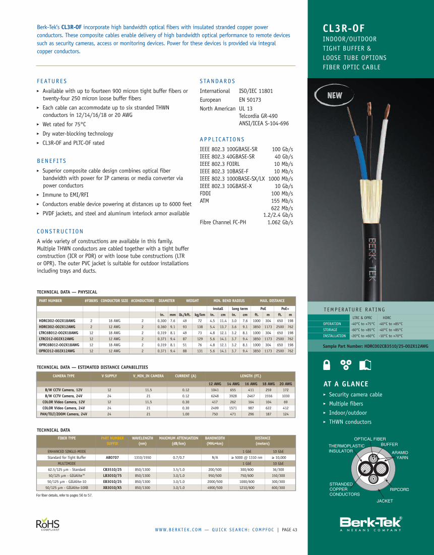
WWW.B ERK T E K . C OM — QUICK S EAR CH : C OMP FO C | PAGE 43
For fiber details, refer to pages 56 to 57.
F EATUR E S� Available with up to fourteen 900 micron tight buffer fibers ortwenty-four 250 micron loose buffer fibers
� Each cable can accommodate up to six stranded THWNconductors in 12/14/16/18 or 20 AWG
� Wet rated for 75°C� Dry water-blocking technology� CL3R-OF and PLTC-OF rated
B EN E F I TS� Superior composite cable design combines optical fiberbandwidth with power for IP cameras or media converter viapower conductors
� Immune to EMI/RFI� Conductors enable device powering at distances up to 6000 feet� PVDF jackets, and steel and aluminum interlock armor available
C ON S T RUC T ION
A wide variety of constructions are available in this family.Multiple THWN conductors are cabled together with a tight bufferconstruction (ICR or PDR) or with loose tube constructions (LTRor OPR). The outer PVC jacket is suitable for outdoor installationsincluding trays and ducts.
S TANDARDS
International ISO/IEC 11801European EN 50173North American UL 13
Telcordia GR-490ANSI/ICEA S-104-696
APP L IC AT ION S
IEEE 802.3 100GBASE-SR 100 Gb/sIEEE 802.3 40GBASE-SR 40 Gb/sIEEE 802.3 FOIRL 10 Mb/sIEEE 802.3 10BASE-F 10 Mb/sIEEE 802.3 1000BASE-SX/LX 1000 Mb/sIEEE 802.3 10GBASE-X 10 Gb/sFDDI 100 Mb/sATM 155 Mb/s
622 Mb/s1.2/2.4 Gb/s
Fibre Channel FC-PH 1.062 Gb/s
Berk-Tek’s CL3R-OF incorporate high bandwidth optical fibers with insulated stranded copper powerconductors. These composite cables enable delivery of high bandwidth optical performance to remote devicessuch as security cameras, access or monitoring devices. Power for these devices is provided via integralcopper conductors.
TECHNICAL DATA
FIBER TYPE PART NUMBER WAVELENGTH MAXIMUM ATTENUATION BANDWIDTH DISTANCESUFFIX (nm) (dB/km) (MHz•km) (meters)
ENHANCED SINGLE-MODE 1 GbE 10 GbE
Standard for Tight Buffer AB0707 1310/1550 0.7/0.7 N/A ≥ 5000 @ 1310 nm ≥ 10,000
MULTIMODE 1 GbE 10 GbE
62.5/125 µm - Standard CB3510/25 850/1300 3.5/1.0 200/500 300/600 36/300
50/125 µm - GIGAlite™ LB3010/75 850/1300 3.0/1.0 950/500 750/600 150/300
50/125 µm - GIGAlite-10 EB3010/25 850/1300 3.0/1.0 2000/500 1000/600 300/300
50/125 µm - GIGAlite-10XB XB3010/X5 850/1300 3.0/1.0 4900/500 1210/600 600/300
TECHNICAL DATA — ESTIMATED DISTANCE CAPABILITIES
CAMERA TYPE V SUPPLY V_MIN_IN CAMERA CURRENT (A) LENGTH (FT.)
12 AWG 14 AWG 16 AWG 18 AWG 20 AWGB/W CCTV Camera, 12V 12 11.5 0.12 1041 655 411 259 172
B/W CCTV Camera, 24V 24 21 0.12 6248 3928 2467 1556 1030
COLOR Video Camera, 12V 12 11.5 0.30 417 262 164 104 69
COLOR Video Camera, 24V 24 21 0.30 2499 1571 987 622 412
PAN/TILT/ZOOM Camera, 24V 24 21 1.00 750 471 296 187 124
TECHNICAL DATA — PHYSICAL
PART NUMBER #FIBERS CONDUCTOR SIZE #CONDUCTORS DIAMETER WEIGHT MIN. BEND RADIUS MAX. DISTANCE
install long term PoE PoE+in. mm lb./kft. kg/km in. cm in. cm ft. m ft. m
HDRC002-002X18AWG 2 18 AWG 2 0.300 7.6 49 72 4.5 11.4 3.0 7.6 1000 304 650 198
HDRC002-002X12AWG 2 12 AWG 2 0.360 9.1 93 138 5.4 13.7 3.6 9.1 3850 1173 2500 762
LTRC6B012-002X18AWG 12 18 AWG 2 0.319 8.1 49 73 4.8 12.1 3.2 8.1 1000 304 650 198
LTRC012-002X12AWG 12 12 AWG 2 0.371 9.4 87 129 5.6 14.1 3.7 9.4 3850 1173 2500 762
OPRC6B012-002X18AWG 12 18 AWG 2 0.319 8.1 51 76 4.8 12.1 3.2 8.1 1000 304 650 198
OPRC012-002X12AWG 12 12 AWG 2 0.371 9.4 88 131 5.6 14.1 3.7 9.4 3850 1173 2500 762
CL3R-OFINDOOR/OUTDOORTIGHT BUFFER &LOOSE TUBE OPTIONSFIBER OPTIC CABLE
T EMPERATUR E RAT ING
OPERATION
STORAGE
INSTALLATION
Sample Part Number: HDRC002CB3510/25-002X12AWG
AT A GLANCE� Security camera cable� Multiple fibers� Indoor/outdoor� THWN conductors
LTRC & OPRC HDRC
-40°C to +75°C -40°C to +85°C
-60°C to +85°C -40°C to +85°C
-20°C to +60°C -10°C to +70°C
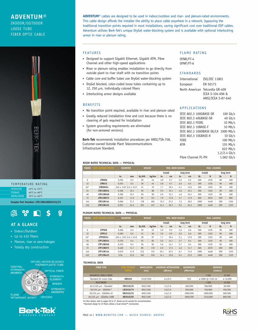
PAGE | WWW.B ERK T E K . C OM — QUICK S EAR CH : ADV FO C44
F E ATUR E S� Designed to support Gigabit Ethernet, Gigabit ATM, FibreChannel and other high-speed applications
� Riser or plenum rating enables installation to go directly fromoutside plant to riser shaft with no transition points
� Cable core and buffer tubes use DryGel water-blocking system� DryGel blocked, color-coded loose tubes containing up to12, 250 µm, individually colored fibers
� Interlocking armor designs available
B EN E F I TS� No transition point required, available in riser and plenum rated� Greatly reduced installation time and cost because there is nocleaning of gels required for installation
� System grounding requirements are eliminated(for non-armored versions)
T EMP ERATUR E RAT ING-40°C to +75°C
-60°C to +85°C
-20°C to +60°C
OPERATION
STORAGE
INSTALLATION
AT A GLANCE� Indoor/Outdoor� Up to 432 fibers� Plenum, riser or zero-halogen� Totally dry construction
ADVENTUM® cables are designed to be used in indoor/outdoor and riser- and plenum-rated environments.This cable design affords the installer the ability to place cable anywhere in a network, bypassing thetraditional transition points required in most installations, saving significant cost over traditional OSP cables.Adventum utilizes Berk-Tek’s unique DryGel water-blocking system and is available with optional interlockingarmor in riser or plenum rating.
ADVENTUM®INDOOR/OUTDOORLOOSE TUBEFIBER OPTIC CABLE
PLENUM RATED TECHNICAL DATA — PHYSICAL
FIBERS PART NUMBER PREFIX DIAMETER WEIGHT MIN. BEND RADIUS MAX. LOADING
install long term install long termin. mm lb./kft. kg/km in. cm in. cm lb. N lb. N
6 LTP006 0.260 6.6 30 45 3.9 9.9 2.6 6.6 300 1335 90 400
12 LTP012 0.260 6.6 31 46 3.9 9.9 2.6 6.6 300 1335 90 400
24* LTP0X024 .245 x .510 6.2 x 12.9 58 87 7.7 19.4 5.1 13.0 300 1335 90 400
24 LTP12B024 0.370 9.4 55 82 5.6 14.1 3.7 9.4 300 1335 90 400
48 LTP12B048 0.370 9.4 56 83 5.6 14.1 3.7 9.4 300 1335 90 400
72 LTP12B072 0.460 11.7 80 119 6.9 17.5 4.6 11.7 600 2670 200 890
144 LTP12B144 0.670 17.0 212 315 10.1 25.5 6.7 17.0 1000 4448 300 1335
432 LTP12B432 0.94 23.9 362 539 14.1 35.8 9.4 23.9 1000 4448 300 1335
Berk-Tek recommends installation procedures per ANSI/TIA-758,Customer-owned Outside Plant TelecommunicationsInfrastructure Standard.
Sample Part Number: LTR12B048EB3010/25
TECHNICAL DATA
FIBER TYPE PART NUMBER WAVELENGTH MAXIMUM ATTENUATION BANDWIDTH DISTANCESUFFIX (nm) (dB/km) (MHz•km) (meters)
ENHANCED SINGLE-MODE 1 GbE 10 GbE
Standard for Loose Tube AB0403 1310/1550 0.4/0.3 N/A ≥ 5000 @ 1310 nm ≥ 10,000
MULTIMODE 1 GbE 10 GbE
62.5/125 µm - Standard CB3510/25 850/1300 3.5/1.0 200/500 300/600 36/300
50/125 µm - GIGAlite™ LB3010/75 850/1300 3.0/1.0 950/500 750/600 150/300
50/125 µm - GIGAlite-10 EB3010/25 850/1300 3.0/1.0 2000/500 1000/600 300/300
50/125 µm - GIGAlite-10XB XB3010/X5 850/1300 3.0/1.0 4900/500 1210/600 600/300
For fiber details, refer to pages 56 to 57. Break-out kit needed for connectorization.*Standard design for 24 fibers utilizes a Dual-UniLite™ construction.
RISER RATED TECHNICAL DATA — PHYSICAL
FIBERS PART NUMBER PREFIX DIAMETER WEIGHT MIN. BEND RADIUS MAX. LOADING
install long term install long termin. mm lb./kft. kg/km in. cm in. cm lb. N lb. N
6 LTR006 0.255 6.5 29 44 3.8 9.7 2.6 6.5 300 1335 90 400
12 LTR012 0.255 6.5 30 44 3.8 9.7 2.6 6.5 300 1335 90 400
24* LTR0X024 .245 x .510 6.2 x 12.9 51 76 7.7 19.4 5.1 13.0 300 1335 90 400
24 LTR12B024 0.396 10.1 59 88 5.9 15.1 4.0 10.1 300 1335 90 400
48 LTR12B048 0.396 10.1 60 90 5.9 15.1 4.0 10.1 300 1335 90 400
72 LTR12B072 0.467 11.9 81 121 7.0 17.8 4.7 11.9 600 2670 200 890
144 LTR12B144 0.696 17.7 178 265 10.7 27.2 7.2 18.2 1000 4448 300 1335
432 LTR12B432 0.953 24.2 301 447 14.3 36.3 9.5 24.2 1000 4448 300 1335
F L AME RAT ING
OFNR/FT-4OFNP/FT-6
S TANDARDS
International ISO/IEC 11801European EN 50173North American Telcordia GR-409
ICEA S-104-696 &ANSI/ICEA S-87-640
APP L IC AT ION S
IEEE 802.3 100GBASE-SR 100 Gb/sIEEE 802.3 40GBASE-SR 40 Gb/sIEEE 802.3 FOIRL 10 Mb/sIEEE 802.3 10BASE-F 10 Mb/sIEEE 802.3 1000BASE-SX/LX 1000 Mb/sIEEE 802.3 10GBASE-X 10 Gb/sFDDI 100 Mb/sATM 155 Mb/s
622 Mb/s1.2/2.4 Gb/s
Fibre Channel FC-PH 1.062 Gb/s
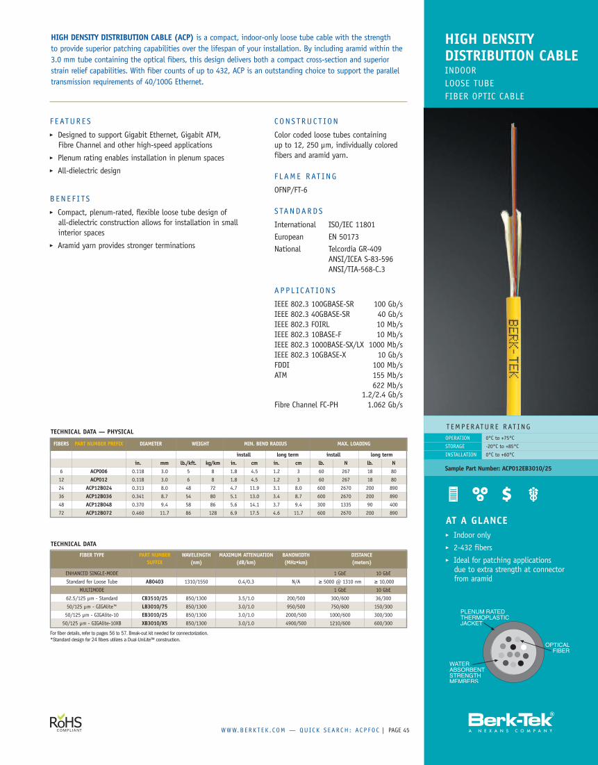
WWW.B ERK T E K . C OM — QUICK S EAR CH : AC P FO C | PAGE 45
HIGH DENSITY DISTRIBUTION CABLE (ACP) is a compact, indoor-only loose tube cable with the strengthto provide superior patching capabilities over the lifespan of your installation. By including aramid within the3.0 mm tube containing the optical fibers, this design delivers both a compact cross-section and superiorstrain relief capabilities. With fiber counts of up to 432, ACP is an outstanding choice to support the paralleltransmission requirements of 40/100G Ethernet.
HIGH DENSITYDISTRIBUTION CABLEINDOORLOOSE TUBEFIBER OPTIC CABLE
T EMPERATUR E RAT ING0°C to +75°C
-20°C to +85°C
0°C to +60°C
OPERATION
STORAGE
INSTALLATION
Sample Part Number: ACP012EB3010/25
AT A GLANCE� Indoor only� 2-432 fibers� Ideal for patching applicationsdue to extra strength at connectorfrom aramid
TECHNICAL DATA — PHYSICAL
FIBERS PART NUMBER PREFIX DIAMETER WEIGHT MIN. BEND RADIUS MAX. LOADING
install long term install long termin. mm lb./kft. kg/km in. cm in. cm lb. N lb. N
6 ACP006 0.118 3.0 5 8 1.8 4.5 1.2 3 60 267 18 80
12 ACP012 0.118 3.0 6 8 1.8 4.5 1.2 3 60 267 18 80
24 ACP12B024 0.313 8.0 48 72 4.7 11.9 3.1 8.0 600 2670 200 890
36 ACP12B036 0.341 8.7 54 80 5.1 13.0 3.4 8.7 600 2670 200 890
48 ACP12B048 0.370 9.4 58 86 5.6 14.1 3.7 9.4 300 1335 90 400
72 ACP12B072 0.460 11.7 86 128 6.9 17.5 4.6 11.7 600 2670 200 890
F E ATUR E S� Designed to support Gigabit Ethernet, Gigabit ATM,Fibre Channel and other high-speed applications
� Plenum rating enables installation in plenum spaces� All-dielectric design
B EN E F I TS� Compact, plenum-rated, flexible loose tube design ofall-dielectric construction allows for installation in smallinterior spaces
� Aramid yarn provides stronger terminations
CONS T RUC T ION
Color coded loose tubes containingup to 12, 250 µm, individually coloredfibers and aramid yarn.
F L AME RAT ING
OFNP/FT-6
S TANDARDS
International ISO/IEC 11801European EN 50173National Telcordia GR-409
ANSI/ICEA S-83-596ANSI/TIA-568-C.3
A P P L IC AT ION S
IEEE 802.3 100GBASE-SR 100 Gb/sIEEE 802.3 40GBASE-SR 40 Gb/sIEEE 802.3 FOIRL 10 Mb/sIEEE 802.3 10BASE-F 10 Mb/sIEEE 802.3 1000BASE-SX/LX 1000 Mb/sIEEE 802.3 10GBASE-X 10 Gb/sFDDI 100 Mb/sATM 155 Mb/s
622 Mb/s1.2/2.4 Gb/s
Fibre Channel FC-PH 1.062 Gb/s
TECHNICAL DATA
FIBER TYPE PART NUMBER WAVELENGTH MAXIMUM ATTENUATION BANDWIDTH DISTANCESUFFIX (nm) (dB/km) (MHz•km) (meters)
ENHANCED SINGLE-MODE 1 GbE 10 GbE
Standard for Loose Tube AB0403 1310/1550 0.4/0.3 N/A ≥ 5000 @ 1310 nm ≥ 10,000
MULTIMODE 1 GbE 10 GbE
62.5/125 µm - Standard CB3510/25 850/1300 3.5/1.0 200/500 300/600 36/300
50/125 µm - GIGAlite™ LB3010/75 850/1300 3.0/1.0 950/500 750/600 150/300
50/125 µm - GIGAlite-10 EB3010/25 850/1300 3.0/1.0 2000/500 1000/600 300/300
50/125 µm - GIGAlite-10XB XB3010/X5 850/1300 3.0/1.0 4900/500 1210/600 600/300
For fiber details, refer to pages 56 to 57. Break-out kit needed for connectorization.*Standard design for 24 fibers utilizes a Dual-UniLite™ construction.
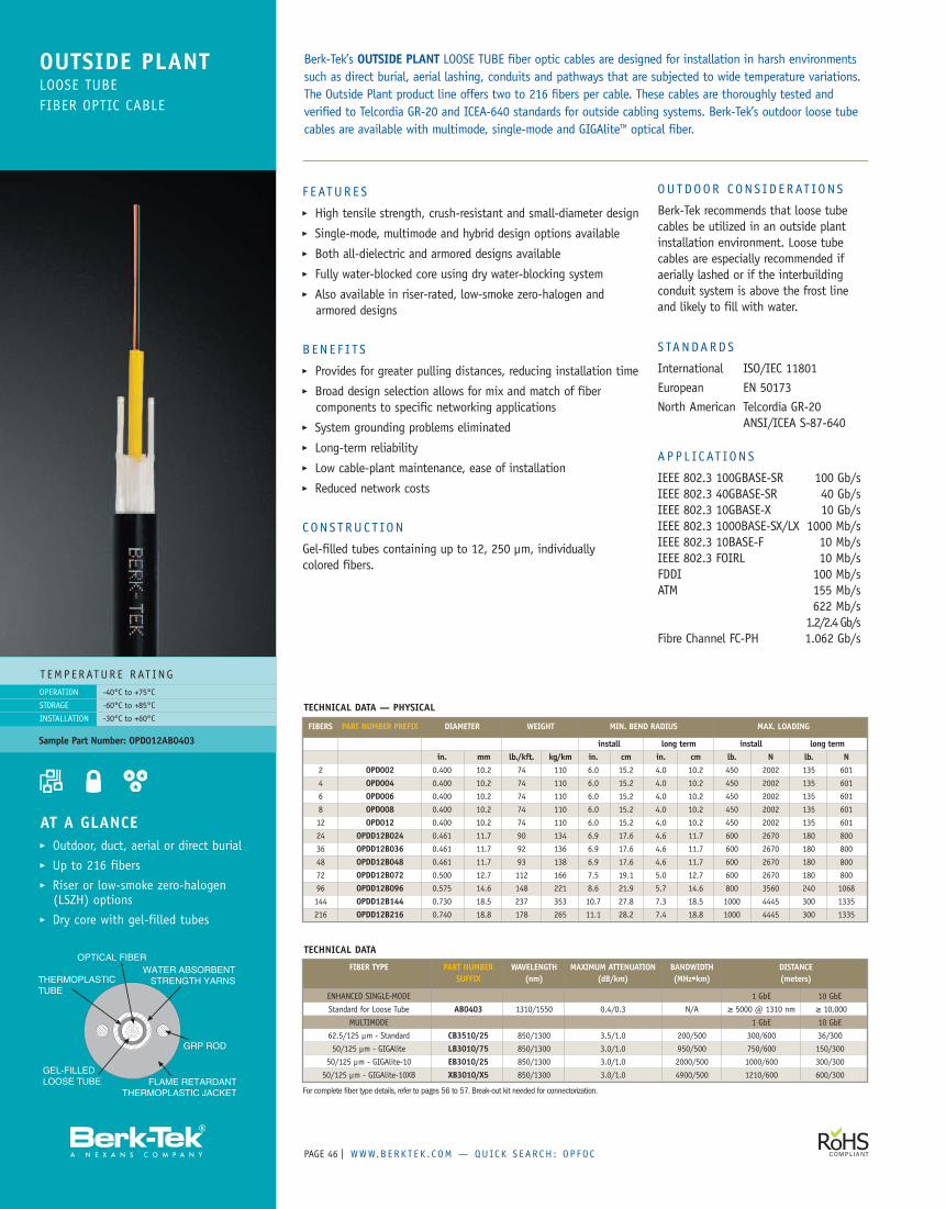
PAGE | WWW.B ERK T E K . C OM — QUICK S EAR CH : O P FO C46
AT A GLANCE� Outdoor, duct, aerial or direct burial� Up to 216 fibers� Riser or low-smoke zero-halogen(LSZH) options
� Dry core with gel-filled tubes
Berk-Tek’s OUTSIDE PLANT LOOSE TUBE fiber optic cables are designed for installation in harsh environmentssuch as direct burial, aerial lashing, conduits and pathways that are subjected to wide temperature variations.The Outside Plant product line offers two to 216 fibers per cable. These cables are thoroughly tested andverified to Telcordia GR-20 and ICEA-640 standards for outside cabling systems. Berk-Tek’s outdoor loose tubecables are available with multimode, single-mode and GIGAliteTM optical fiber.
OUTSIDE PLANTLOOSE TUBEFIBER OPTIC CABLE
T EMPERATUR E RAT INGOPERATION
STORAGE
INSTALLATION
-40°C to +75°C
-60°C to +85°C
-30°C to +60°C
Sample Part Number: OPD012AB0403
F EATUR E S� High tensile strength, crush-resistant and small-diameter design� Single-mode, multimode and hybrid design options available� Both all-dielectric and armored designs available� Fully water-blocked core using dry water-blocking system� Also available in riser-rated, low-smoke zero-halogen andarmored designs
B EN E F I TS� Provides for greater pulling distances, reducing installation time� Broad design selection allows for mix and match of fibercomponents to specific networking applications
� System grounding problems eliminated� Long-term reliability� Low cable-plant maintenance, ease of installation� Reduced network costs
C ON S T RUC T ION
Gel-filled tubes containing up to 12, 250 µm, individuallycolored fibers.
OU TDOOR CONS I D E RAT ION S
Berk-Tek recommends that loose tubecables be utilized in an outside plantinstallation environment. Loose tubecables are especially recommended ifaerially lashed or if the interbuildingconduit system is above the frost lineand likely to fill with water.
S TANDARDS
International ISO/IEC 11801European EN 50173North American Telcordia GR-20
ANSI/ICEA S-87-640
APP L IC AT ION S
IEEE 802.3 100GBASE-SR 100 Gb/sIEEE 802.3 40GBASE-SR 40 Gb/sIEEE 802.3 10GBASE-X 10 Gb/sIEEE 802.3 1000BASE-SX/LX 1000 Mb/sIEEE 802.3 10BASE-F 10 Mb/sIEEE 802.3 FOIRL 10 Mb/sFDDI 100 Mb/sATM 155 Mb/s
622 Mb/s1.2/2.4Gb/s
Fibre Channel FC-PH 1.062 Gb/s
TECHNICAL DATA — PHYSICAL
FIBERS PART NUMBER PREFIX DIAMETER WEIGHT MIN. BEND RADIUS MAX. LOADING
install long term install long termin. mm lb./kft. kg/km in. cm in. cm lb. N lb. N
2 OPD002 0.400 10.2 74 110 6.0 15.2 4.0 10.2 450 2002 135 601
4 OPD004 0.400 10.2 74 110 6.0 15.2 4.0 10.2 450 2002 135 601
6 OPD006 0.400 10.2 74 110 6.0 15.2 4.0 10.2 450 2002 135 601
8 OPD008 0.400 10.2 74 110 6.0 15.2 4.0 10.2 450 2002 135 601
12 OPD012 0.400 10.2 74 110 6.0 15.2 4.0 10.2 450 2002 135 601
24 OPDD12B024 0.461 11.7 90 134 6.9 17.6 4.6 11.7 600 2670 180 800
36 OPDD12B036 0.461 11.7 92 136 6.9 17.6 4.6 11.7 600 2670 180 800
48 OPDD12B048 0.461 11.7 93 138 6.9 17.6 4.6 11.7 600 2670 180 800
72 OPDD12B072 0.500 12.7 112 166 7.5 19.1 5.0 12.7 600 2670 180 800
96 OPDD12B096 0.575 14.6 148 221 8.6 21.9 5.7 14.6 800 3560 240 1068
144 OPDD12B144 0.730 18.5 237 353 10.7 27.8 7.3 18.5 1000 4445 300 1335
216 OPDD12B216 0.740 18.8 178 265 11.1 28.2 7.4 18.8 1000 4445 300 1335
TECHNICAL DATA
FIBER TYPE PART NUMBER WAVELENGTH MAXIMUM ATTENUATION BANDWIDTH DISTANCESUFFIX (nm) (dB/km) (MHz•km) (meters)
ENHANCED SINGLE-MODE 1 GbE 10 GbE
Standard for Loose Tube AB0403 1310/1550 0.4/0.3 N/A ≥ 5000 @ 1310 nm ≥ 10,000
MULTIMODE 1 GbE 10 GbE
62.5/125 µm - Standard CB3510/25 850/1300 3.5/1.0 200/500 300/600 36/300
50/125 µm - GIGAlite LB3010/75 850/1300 3.0/1.0 950/500 750/600 150/300
50/125 µm - GIGAlite-10 EB3010/25 850/1300 3.0/1.0 2000/500 1000/600 300/300
50/125 µm - GIGAlite-10XB XB3010/X5 850/1300 3.0/1.0 4900/500 1210/600 600/300
For complete fiber type details, refer to pages 56 to 57. Break-out kit needed for connectorization.
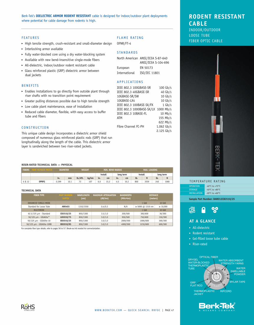
WWW.B ERK T E K . C OM — QUICK S EAR CH : R R FO C | PAGE 47
F E ATUR E S� High tensile strength, crush-resistant and small-diameter design� Interlocking armor available� Fully water-blocked core using a dry water-blocking system� Available with new bend-insensitive single-mode fibers� All-dielectric, indoor/outdoor rodent resistant cable� Glass reinforced plastic (GRP) dielectric armor betweendual jackets
B EN E F I TS� Enables installations to go directly from outside plant throughriser shafts with no transition point requirement
� Greater pulling distances possible due to high tensile strength� Low cable plant maintenance, ease of installation� Reduced cable diameter, flexible, with easy access to buffertube and fibers
C ON S T RUC T ION
This unique cable design incorporates a dielectric armor shieldcomposed of numerous glass reinforced plastic rods (GRP) that runlongitudinally along the length of the cable. This dielectric armorlayer is sandwiched between two riser-rated jackets.
F L AME RAT ING
OFNR/FT-4
S TANDARDS
North American ANSI/ICEA S-87-640ANSI/ICEA S-104-696
European EN 50173International ISO/IEC 11801
APP L IC AT ION S
IEEE 802.3 100GBASE-SR 100 Gb/sIEEE 802.3 40GBASE-SR 40 Gb/s10GBASE-SR/SW 10 Gb/s10GBASE-LX4 10 Gb/sIEEE 802.3 100BASE-SX/FX 1 Gb/sIEEE 802.3 1000BASE-SX/LX 1000 Mb/sIEEE 802.3 10BASE-FL 10 Mb/sATM 155 Mb/s
622 Mb/sFibre Channel FC-PH 1.062 Gb/s
2.125 Gb/s
AT A GLANCE� All-dielectric� Rodent resistant� Gel-filled loose tube cable� Riser-rated
Berk-Tek’s DIELECTRIC ARMOR RODENT RESISTANT cable is designed for indoor/outdoor plant deploymentswhere potential for cable damage from rodents is high.
RODENT RESISTANTCABLEINDOOR/OUTDOORLOOSE TUBEFIBER OPTIC CABLE
T EMPERATUR E RAT ING-40°C to +75°C
-40°C to +85°C
-20°C to +60°C
OPERATION
STORAGE
INSTALLATION
Sample Part Number: DAR012CB3510/25
RISER-RATED TECHNICAL DATA — PHYSICAL
FIBERS PART NUMBER PREFIX DIAMETER WEIGHT MIN. BEND RADIUS MAX. LOADING
install long term install long termin. mm lb./kft. kg/km in. cm in. cm lb. N lb. N
6 & 12 OPRFG 0.399 10.1 72 107 6.0 15.2 4.0 10.2 800 3559 240 1068
TECHNICAL DATA
FIBER TYPE PART NUMBER WAVELENGTH MAXIMUM ATTENUATION BANDWIDTH DISTANCESUFFIX (nm) (dB/km) (MHz•km) (meters)
ENHANCED SINGLE-MODE 1 GbE 10 GbE
Standard for Loose Tube AB0403 1310/1550 0.4/0.3 N/A ≥ 5000 @ 1310 nm ≥ 10,000
MULTIMODE 1 GbE 10 GbE
62.5/125 µm - Standard CB3510/25 850/1300 3.5/1.0 200/500 300/600 36/300
50/125 µm - GIGAlite™ LB3010/75 850/1300 3.0/1.0 950/500 750/600 150/300
50/125 µm - GIGAlite-10 EB3010/25 850/1300 3.0/1.0 2000/500 1000/600 300/300
50/125 µm - GIGAlite-10XB XB3010/X5 850/1300 3.0/1.0 4900/500 1210/600 600/300
For complete fiber type details, refer to pages 56 to 57. Break-out kit needed for connectorization.
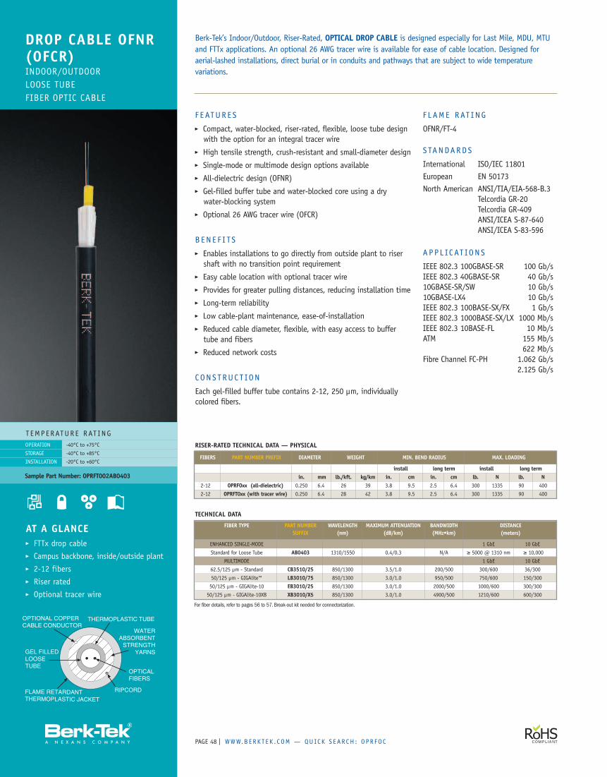
PAGE | WWW.B ERK T E K . C OM — QUICK S EAR CH : O PR FO C48
F E ATUR E S� Compact, water-blocked, riser-rated, flexible, loose tube designwith the option for an integral tracer wire
� High tensile strength, crush-resistant and small-diameter design� Single-mode or multimode design options available� All-dielectric design (OFNR)� Gel-filled buffer tube and water-blocked core using a drywater-blocking system
� Optional 26 AWG tracer wire (OFCR)
B EN E F I TS� Enables installations to go directly from outside plant to risershaft with no transition point requirement
� Easy cable location with optional tracer wire� Provides for greater pulling distances, reducing installation time� Long-term reliability� Low cable-plant maintenance, ease-of-installation� Reduced cable diameter, flexible, with easy access to buffertube and fibers
� Reduced network costs
C ON S T RUC T ION
Each gel-filled buffer tube contains 2-12, 250 µm, individuallycolored fibers.
F L AME RAT ING
OFNR/FT-4
S TANDARDS
International ISO/IEC 11801European EN 50173North American ANSI/TIA/EIA-568-B.3
Telcordia GR-20Telcordia GR-409ANSI/ICEA S-87-640ANSI/ICEA S-83-596
APP L IC AT ION S
IEEE 802.3 100GBASE-SR 100 Gb/sIEEE 802.3 40GBASE-SR 40 Gb/s10GBASE-SR/SW 10 Gb/s10GBASE-LX4 10 Gb/sIEEE 802.3 100BASE-SX/FX 1 Gb/sIEEE 802.3 1000BASE-SX/LX 1000 Mb/sIEEE 802.3 10BASE-FL 10 Mb/sATM 155 Mb/s
622 Mb/sFibre Channel FC-PH 1.062 Gb/s
2.125 Gb/s
Berk-Tek’s Indoor/Outdoor, Riser-Rated, OPTICAL DROP CABLE is designed especially for Last Mile, MDU, MTUand FTTx applications. An optional 26 AWG tracer wire is available for ease of cable location. Designed foraerial-lashed installations, direct burial or in conduits and pathways that are subject to wide temperaturevariations.
DROP CABLE OFNR(OFCR)INDOOR/OUTDOORLOOSE TUBEFIBER OPTIC CABLE
T EMPERATUR E RAT INGOPERATION
STORAGE
INSTALLATION
-40°C to +75°C
-40°C to +85°C
-20°C to +60°C
Sample Part Number: OPRFT002AB0403
AT A GLANCE� FTTx drop cable� Campus backbone, inside/outside plant� 2-12 fibers� Riser rated� Optional tracer wire
RISER-RATED TECHNICAL DATA — PHYSICAL
FIBERS PART NUMBER PREFIX DIAMETER WEIGHT MIN. BEND RADIUS MAX. LOADING
install long term install long termin. mm lb./kft. kg/km in. cm in. cm lb. N lb. N
2-12 OPRFOxx (all-dielectric) 0.250 6.4 26 39 3.8 9.5 2.5 6.4 300 1335 90 400
2-12 OPRFT0xx (with tracer wire) 0.250 6.4 28 42 3.8 9.5 2.5 6.4 300 1335 90 400
TECHNICAL DATA
FIBER TYPE PART NUMBER WAVELENGTH MAXIMUM ATTENUATION BANDWIDTH DISTANCESUFFIX (nm) (dB/km) (MHz•km) (meters)
ENHANCED SINGLE-MODE 1 GbE 10 GbE
Standard for Loose Tube AB0403 1310/1550 0.4/0.3 N/A ≥ 5000 @ 1310 nm ≥ 10,000
MULTIMODE 1 GbE 10 GbE
62.5/125 µm - Standard CB3510/25 850/1300 3.5/1.0 200/500 300/600 36/300
50/125 µm - GIGAlite™ LB3010/75 850/1300 3.0/1.0 950/500 750/600 150/300
50/125 µm - GIGAlite-10 EB3010/25 850/1300 3.0/1.0 2000/500 1000/600 300/300
50/125 µm - GIGAlite-10XB XB3010/X5 850/1300 3.0/1.0 4900/500 1210/600 600/300
For fiber details, refer to pages 56 to 57. Break-out kit needed for connectorization.
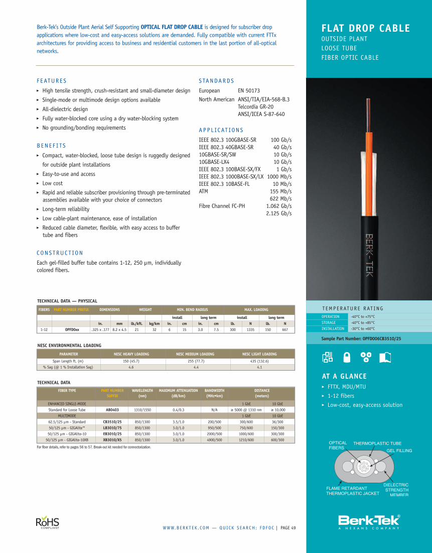
WWW.B ERK T E K . C OM — QUICK S EAR CH : F D FO C | PAGE 49
F E ATUR E S� High tensile strength, crush-resistant and small-diameter design� Single-mode or multimode design options available� All-dielectric design� Fully water-blocked core using a dry water-blocking system� No grounding/bonding requirements
B EN E F I TS� Compact, water-blocked, loose tube design is ruggedly designed
for outside plant installations� Easy-to-use and access� Low cost� Rapid and reliable subscriber provisioning through pre-terminatedassemblies available with your choice of connectors
� Long-term reliability� Low cable-plant maintenance, ease of installation� Reduced cable diameter, flexible, with easy access to buffertube and fibers
C ON S T RUC T ION
Each gel-filled buffer tube contains 1-12, 250 µm, individuallycolored fibers.
S TANDARDS
European EN 50173North American ANSI/TIA/EIA-568-B.3
Telcordia GR-20ANSI/ICEA S-87-640
APP L IC AT ION S
IEEE 802.3 100GBASE-SR 100 Gb/sIEEE 802.3 40GBASE-SR 40 Gb/s10GBASE-SR/SW 10 Gb/s10GBASE-LX4 10 Gb/sIEEE 802.3 100BASE-SX/FX 1 Gb/sIEEE 802.3 1000BASE-SX/LX 1000 Mb/sIEEE 802.3 10BASE-FL 10 Mb/sATM 155 Mb/s
622 Mb/sFibre Channel FC-PH 1.062 Gb/s
2.125 Gb/s
Berk-Tek’s Outside Plant Aerial Self Supporting OPTICAL FLAT DROP CABLE is designed for subscriber dropapplications where low-cost and easy-access solutions are demanded. Fully compatible with current FTTxarchitectures for providing access to business and residential customers in the last portion of all-opticalnetworks.
FLAT DROP CABLEOUTSIDE PLANTLOOSE TUBEFIBER OPTIC CABLE
T EMPERATUR E RAT ING-40°C to +75°C
-40°C to +85°C
-30°C to +60°C
OPERATION
STORAGE
INSTALLATION
Sample Part Number: OPFD006CB3510/25
AT A GLANCE� FTTX, MDU/MTU� 1-12 fibers� Low-cost, easy-access solution
NESC ENVIRONMENTAL LOADING
PARAMETER NESC HEAVY LOADING NESC MEDIUM LOADING NESC LIGHT LOADING
Span Length ft. (m) 150 (45.7) 255 (77.7) 435 (132.6)
% Sag (@ 1 % Installation Sag) 4.6 4.4 4.1
TECHNICAL DATA — PHYSICAL
FIBERS PART NUMBER PREFIX DIMENSIONS WEIGHT MIN. BEND RADIUS MAX. LOADING
install long term install long termin. mm lb./kft. kg/km in. cm in. cm lb. N lb. N
1-12 OPFD0xx .325 x .177 8.2 x 4.5 21 32 6 15 3.0 7.5 300 1335 150 667
TECHNICAL DATA
FIBER TYPE PART NUMBER WAVELENGTH MAXIMUM ATTENUATION BANDWIDTH DISTANCESUFFIX (nm) (dB/km) (MHz•km) (meters)
ENHANCED SINGLE-MODE 1 GbE 10 GbE
Standard for Loose Tube AB0403 1310/1550 0.4/0.3 N/A ≥ 5000 @ 1310 nm ≥ 10,000
MULTIMODE 1 GbE 10 GbE
62.5/125 µm - Standard CB3510/25 850/1300 3.5/1.0 200/500 300/600 36/300
50/125 µm - GIGAlite™ LB3010/75 850/1300 3.0/1.0 950/500 750/600 150/300
50/125 µm - GIGAlite-10 EB3010/25 850/1300 3.0/1.0 2000/500 1000/600 300/300
50/125 µm - GIGAlite-10XB XB3010/X5 850/1300 3.0/1.0 4900/500 1210/600 600/300
For fiber details, refer to pages 56 to 57. Break-out kit needed for connectorization.
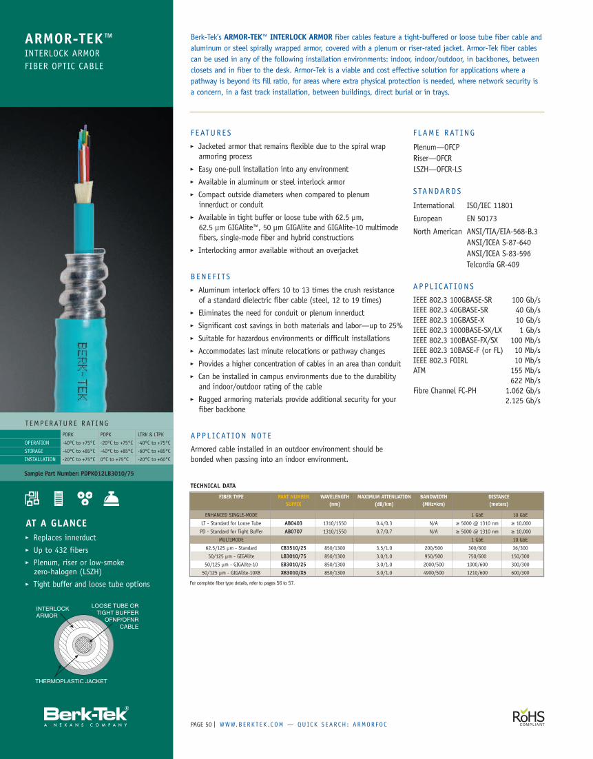
PAGE | WWW.B ERK T E K . C OM — QUICK S EAR CH : ARMOR FO C50
F E ATUR E S� Jacketed armor that remains flexible due to the spiral wraparmoring process
� Easy one-pull installation into any environment� Available in aluminum or steel interlock armor� Compact outside diameters when compared to plenuminnerduct or conduit
� Available in tight buffer or loose tube with 62.5 µm,62.5 µm GIGAlite™, 50 µm GIGAlite and GIGAlite-10 multimodefibers, single-mode fiber and hybrid constructions
� Interlocking armor available without an overjacket
B EN E F I TS� Aluminum interlock offers 10 to 13 times the crush resistanceof a standard dielectric fiber cable (steel, 12 to 19 times)
� Eliminates the need for conduit or plenum innerduct� Significant cost savings in both materials and labor—up to 25%� Suitable for hazardous environments or difficult installations� Accommodates last minute relocations or pathway changes� Provides a higher concentration of cables in an area than conduit� Can be installed in campus environments due to the durabilityand indoor/outdoor rating of the cable
� Rugged armoring materials provide additional security for yourfiber backbone
APP L IC AT ION NOT E
Armored cable installed in an outdoor environment should bebonded when passing into an indoor environment.
F L AME RAT ING
Plenum—OFCPRiser—OFCRLSZH—OFCR-LS
S TANDARDS
International ISO/IEC 11801
European EN 50173
North American ANSI/TIA/EIA-568-B.3ANSI/ICEA S-87-640ANSI/ICEA S-83-596Telcordia GR-409
APP L IC AT ION S
IEEE 802.3 100GBASE-SR 100 Gb/sIEEE 802.3 40GBASE-SR 40 Gb/sIEEE 802.3 10GBASE-X 10 Gb/sIEEE 802.3 1000BASE-SX/LX 1 Gb/sIEEE 802.3 100BASE-FX/SX 100 Mb/sIEEE 802.3 10BASE-F (or FL) 10 Mb/sIEEE 802.3 FOIRL 10 Mb/sATM 155 Mb/s
622 Mb/sFibre Channel FC-PH 1.062 Gb/s
2.125 Gb/s
Berk-Tek’s ARMOR-TEK™ INTERLOCK ARMOR fiber cables feature a tight-buffered or loose tube fiber cable andaluminum or steel spirally wrapped armor, covered with a plenum or riser-rated jacket. Armor-Tek fiber cablescan be used in any of the following installation environments: indoor, indoor/outdoor, in backbones, betweenclosets and in fiber to the desk. Armor-Tek is a viable and cost effective solution for applications where apathway is beyond its fill ratio, for areas where extra physical protection is needed, where network security isa concern, in a fast track installation, between buildings, direct burial or in trays.
ARMOR-TEK™INTERLOCK ARMORFIBER OPTIC CABLE
T EMPERATUR E RAT ING
OPERATION
STORAGE
INSTALLATION
PDRK PDPK LTRK & LTPK
-40°C to +75°C -20°C to +75°C -40°C to +75°C
-40°C to +85°C -40°C to +85°C -60°C to +85°C
-20°C to +75°C 0°C to +75°C -20°C to +60°C
Sample Part Number: PDPK012LB3010/75
AT A GLANCE� Replaces innerduct� Up to 432 fibers� Plenum, riser or low-smokezero-halogen (LSZH)
� Tight buffer and loose tube options
TECHNICAL DATA
FIBER TYPE PART NUMBER WAVELENGTH MAXIMUM ATTENUATION BANDWIDTH DISTANCESUFFIX (nm) (dB/km) (MHz•km) (meters)
ENHANCED SINGLE-MODE 1 GbE 10 GbE
LT - Standard for Loose Tube AB0403 1310/1550 0.4/0.3 N/A ≥ 5000 @ 1310 nm ≥ 10,000
PD - Standard for Tight Buffer AB0707 1310/1550 0.7/0.7 N/A ≥ 5000 @ 1310 nm ≥ 10,000
MULTIMODE 1 GbE 10 GbE
62.5/125 µm - Standard CB3510/25 850/1300 3.5/1.0 200/500 300/600 36/300
50/125 µm - GIGAlite LB3010/75 850/1300 3.0/1.0 950/500 750/600 150/300
50/125 µm - GIGAlite-10 EB3010/25 850/1300 3.0/1.0 2000/500 1000/600 300/300
50/125 µm - GIGAlite-10XB XB3010/X5 850/1300 3.0/1.0 4900/500 1210/600 600/300
For complete fiber type details, refer to pages 56 to 57.
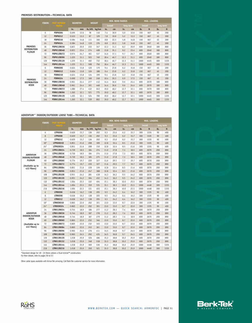
WWW.B ERK T E K . C OM — QUICK S EAR CH : ARMOR FO C | PAGE 51
ARMOR-TEK
™PREFIX
PREFIX
*Standard design for 18 - 24 fibers utilizes a Dual-UniLite™ construction.For fiber details, refer to pages 56 to 57.
Other cable types available with Armor-Tek armoring. Call Berk-Tek customer service for more information.
PREMISES DISTRIBUTION—TECHNICAL DATA
ADVENTUM™ INDOOR/OUTDOOR LOOSE TUBE—TECHNICAL DATA
FIBERS PART NUMBER DIAMETER WEIGHTMIN. BEND RADIUS MAX. LOADING
install long term install long termin. mm lb./kft. kg/km in. cm in. cm lb. N lb. N
6 LTPK006 0.620 15.7 136 202 9.3 23.6 6.2 15.7 300 1335 90 400
8 LTPK008 0.620 15.7 136 202 9.3 23.6 6.2 15.7 300 1335 90 400
12 LTPK012 0.620 15.7 136 202 9.3 23.6 6.2 15.7 300 1335 90 400
18* LTPK0X018 0.851 21.6 208 309 12.8 32.4 8.5 21.6 300 1335 90 400
24* LTPK0X024 0.851 21.6 208 310 12.8 32.4 8.5 21.6 300 1335 90 400
24 LTPK12B024 0.730 18.5 184 274 11.0 27.8 7.3 18.5 600 2670 200 890
36 LTPK12B036 0.730 18.5 184 274 11.0 27.8 7.3 18.5 600 2670 200 890
48 LTPK12B048 0.730 18.5 185 275 11.0 27.8 7.3 18.5 600 2670 200 890
60 LTPK12B060 0.774 19.7 220 327 11.6 29.5 7.7 19.7 600 2670 200 890
72 LTPK12B072 0.774 19.7 220 327 11.6 29.5 7.7 19.7 600 2670 200 890
84 LTPK12B084 0.851 21.6 228 339 12.8 32.4 8.5 21.6 600 2670 200 890
96 LTPK12B096 0.851 21.6 247 368 12.8 32.4 8.5 21.6 600 2670 200 890
108 LTPK12B108 0.951 24.2 281 418 14.3 36.2 9.5 24.2 600 2670 200 890
120 LTPK12B120 0.951 24.2 304 452 14.3 36.2 9.5 24.2 600 2670 200 890
132 LTPK12B132 1.004 25.5 332 494 15.1 38.3 10.0 25.5 600 2670 200 890
144 LTPK12B144 1.004 25.5 359 535 15.1 38.3 10.0 25.5 1000 4448 300 1335
216 LTPK12B216 1.004 25.5 331 493 15.1 38.3 10.0 25.5 1000 4448 300 1335
6 LTRK006 0.636 16.2 138 205 9.5 24.2 6.4 16.2 300 1335 90 400
8 LTRK008 0.636 16.2 138 205 9.5 24.2 6.4 16.2 300 1335 90 400
12 LTRK012 0.636 16.2 138 205 9.5 24.2 6.4 16.2 300 1335 90 400
18* LTRK0X018 0.865 22.0 202 301 13.0 33.0 8.7 22.0 300 1335 90 400
24* LTRK0X024 0.865 22.0 202 301 13.0 33.0 8.7 22.0 300 1335 90 400
24 LTRK12B024 0.744 18.9 186 277 11.2 28.3 7.4 18.9 600 2670 200 890
36 LTRK12B036 0.744 18.9 187 278 11.2 28.3 7.4 18.9 600 2670 200 890
48 LTRK12B048 0.744 18.9 187 279 11.2 28.3 7.4 18.9 600 2670 200 890
60 LTRK12B060 0.865 22.0 232 346 13.0 33.0 8.7 22.0 600 2670 200 890
72 LTRK12B072 0.865 22.0 232 345 13.0 33.0 8.7 22.0 600 2670 200 890
84 LTRK12B084 0.865 22.0 243 361 13.0 33.0 8.7 22.0 600 2670 200 890
96 LTRK12B096 0.965 24.5 276 411 14.5 36.8 9.7 24.5 600 2670 200 890
108 LTRK12B108 0.965 24.5 292 435 14.5 36.8 9.7 24.5 600 2670 200 890
120 LTRK12B120 1.018 25.9 326 486 15.3 38.8 10.2 25.9 600 2670 200 890
132 LTRK12B132 1.018 25.9 348 518 15.3 38.8 10.2 25.9 600 2670 200 890
144 LTRK12B144 1.018 25.9 360 536 15.3 38.8 10.2 25.9 1000 4448 300 1335
216 LTRK12B216 1.018 25.9 350 521 15.3 38.8 10.2 25.9 1000 4448 300 1335
FIBERS PART NUMBER DIAMETER WEIGHTMIN. BEND RADIUS MAX. LOADING
install long term install long termin. mm lb./kft. kg/km in. cm in. cm lb. N lb. N
6 PDPK006 0.495 12.6 78 116 7.4 18.9 5.0 12.6 150 667 45 200
12 PDPK012 0.523 13.3 87 129 7.8 19.9 5.2 13.3 150 667 45 200
18 PDPK018 0.584 14.8 111 166 8.8 22.3 5.8 14.8 150 667 45 200
24 PDPK024 0.584 14.8 119 176 8.8 22.3 5.8 14.8 150 667 45 200
36 PDPK12B036 0.821 20.9 233 347 12.3 31.3 8.2 20.9 600 2640 180 800
48 PDPK12B048 0.921 23.4 274 408 13.8 35.1 9.2 23.4 600 2640 180 800
72 PDPK12B072 0.974 24.7 361 537 14.6 37.1 9.7 24.7 600 2640 180 800
96 PDPK12B096 1.225 31.1 503 749 18.4 46.7 12.3 31.1 600 2640 180 800
120 PDPK12B120 1.225 31.1 492 732 18.4 46.7 12.3 31.1 1000 4445 300 1335
144 PDPK12B144 1.225 31.1 508 756 18.4 46.7 12.3 31.1 1000 4445 300 1335
6 PDRK006 0.624 15.8 120 179 9.4 23.8 6.2 15.8 150 667 45 200
12 PDRK012 0.624 15.8 126 188 9.4 23.8 6.2 15.8 150 667 45 200
18 PDRK018 0.624 15.8 134 199 9.4 23.8 6.2 15.8 150 667 45 200
24 PDRK024 0.690 17.5 166 248 10.4 26.3 6.9 17.5 150 667 45 200
36 PDRK12B036 0.961 24.4 277 412 14.4 36.6 9.6 24.4 600 2670 180 800
48 PDRK12B048 0.961 24.4 301 448 14.4 36.6 9.6 24.4 600 2670 180 800
72 PDRK12B072 1.080 27.4 432 643 19.0 48.2 12.7 32.1 600 2670 180 800
96 PDRK12B096 1.265 32.1 521 775 19.0 48.2 12.7 32.1 600 2670 180 800
120 PDRK12B120 1.265 32.1 524 780 19.0 48.2 12.7 32.1 1000 4445 300 1335
144 PDRK12B144 1.265 32.1 539 802 19.0 48.2 12.7 32.1 1000 4445 300 1335
PREMISESDISTRIBUTION
RISER
PREMISESDISTRIBUTION
PLENUM
ADVENTUMINDOOR/OUTDOOR
PLENUM
(Available up to432 fibers)
ADVENTUMINDOOR/OUTDOOR
RISER
(Available up to432 fibers)
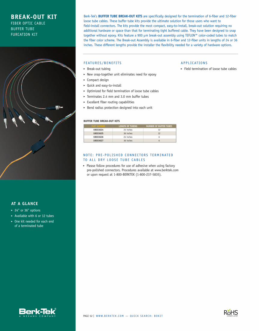
PAGE | WWW.B ERK T E K . C OM — QUICK S EAR CH : BOK I T52
BREAK-OUT KITFIBER OPTIC CABLEBUFFER TUBEFURCATION KIT
AT A GLANCE� 24" or 36" options� Available with 6 or 12 tubes� One kit needed for each endof a terminated tube
F EATUR E S /B EN E F I TS� Break-out tubing� New snap-together unit eliminates need for epoxy� Compact design� Quick and easy-to-install� Optimized for field termination of loose tube cables� Terminates 2.4 mm and 3.0 mm buffer tubes� Excellent fiber routing capabilities� Bend radius protection designed into each unit
A P P L IC AT ION S� Field termination of loose tube cables
Berk-Tek’s BUFFER TUBE BREAK-OUT KITS are specifically designed for the termination of 6-fiber and 12-fiberloose tube cables. These buffer tube kits provide the ultimate solution for those users who want tofield-install connectors. The kits provide the most compact, easy-to-install, break-out solution requiring noadditional hardware or space than that for terminating tight buffered cable. They have been designed to snaptogether without epoxy. Kits feature a 900 µm break-out assembly using TEFLON™ color-coded tubes to matchthe fiber color scheme. The Break-out Assembly is available in 6-fiber and 12-fiber units in lengths of 24 or 36inches. These different lengths provide the installer the flexibility needed for a variety of hardware options.
BUFFER TUBE BREAK-OUT KITS
PART NUMBER LENGTH OF TUBING NUMBER OF BUFFER TUBES10033624 24 inches 12
10033625 36 inches 12
10033626 24 inches 6
10033627 36 inches 6
NOT E : P R E - PO L ISH ED CONNE C TOR S T E RM INAT EDTO A L L DR Y LOO S E TUBE CAB L E S� Please follow procedures for use of adhesive when using factorypre-polished connectors. Procedures available at www.berktek.comor upon request at 1-800-BERKTEK (1-800-237-5835).
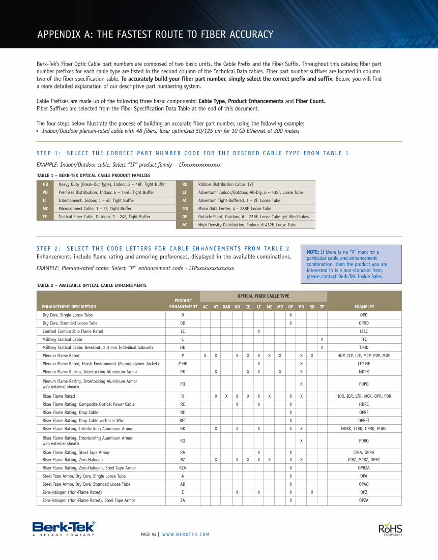
PAGE | WWW.B ERK T E K . C OM54
AC AT DAR HD IC LT MC MD OP PD RD TF
Dry Core, Single Loose Tube D X OPD
Dry Core, Stranded Loose Tube DD X OPDD
Limited Combustible Flame Rated LC X LTLC
Military Tactical Cable C X TFC
Military Tactical Cable, Breakout, 2.0 mm Individual Subunits HD X TFHD
Plenum Flame Rated P X X X X X X X X X HDP, ICP, LTP, MCP, PDP, MDP
Plenum Flame Rated, Harsh Environment (Fluoropolymer Jacket) P HE X X LTP HE
Plenum Flame Rating, Interlocking Aluminum Armor PK X X X X X MDPK
Plenum Flame Rating, Interlocking Aluminum Armor PQ X PDPQw/o external sheath
Riser Flame Rated R X X X X X X X X HDR, ICR, LTR, MCR, OPR, PDR
Riser Flame Rating, Composite Optical Power Cable RC X X X HDRC
Riser Flame Rating, Drop Cable RF X OPRF
Riser Flame Rating, Drop Cable w/Tracer Wire RFT X OPRFT
Riser Flame Rating, Interlocking Aluminum Armor RK X X X X X HDRK, LTRK, OPRK, PDRK
Riser Flame Rating, Interlocking Aluminum Armor RQ X PDRQw/o external sheath
Riser Flame Rating, Steel Tape Armor RA X X LTRA, OPRA
Riser Flame Rating, Zero-Halogen RZ X X X X X X X ICRZ, MCRZ, OPRZ
Riser Flame Rating, Zero-Halogen, Steel Tape Armor RZA X OPRZA
Steel Tape Armor, Dry Core, Single Loose Tube A X OPA
Steel Tape Armor, Dry Core, Stranded Loose Tube AD X OPAD
Zero-Halogen (Non-Flame Rated) Z X X X X OPZ
Zero-Halogen (Non-Flame Rated), Steel Tape Armor ZA X OPZA
OPTICAL CABLE PART NUMBER BUILDING GUIDELINES
TABLE 2 – AVAILABLE OPTICAL CABLE ENHANCEMENTS
TABLE 1 – BERK-TEK OPTICAL CABLE PRODUCT FAMILIES
HD Heavy Duty (Break-Out Type), Indoor, 2 – 48F, Tight Buffer
PD Premises Distribution, Indoor, 6 – 144F, Tight Buffer
IC Interconnect, Indoor, 1 – 4F, Tight Buffer
MC Microconnect Cable, 1 – 2F, Tight Buffer
TF Tactical Fiber Cable, Outdoor, 2 – 24F, Tight Buffer
Berk-Tek’s Fiber Optic Cable part numbers are composed of two basic units, the Cable Prefix and the Fiber Suffix. Throughout this catalog fiber partnumber prefixes for each cable type are listed in the second column of the Technical Data tables. Fiber part number suffixes are located in columntwo of the fiber specification table. To accurately build your fiber part number, simply select the correct prefix and suffix. Below, you will finda more detailed explanation of our descriptive part numbering system.
Cable Prefixes are made up of the following three basic components: Cable Type, Product Enhancements and Fiber Count.Fiber Suffixes are selected from the Fiber Specification Data Table at the end of this document.
The four steps below illustrate the process of building an accurate fiber part number, using the following example:� Indoor/Outdoor plenum-rated cable with 48 fibers, laser optimized 50/125 µm for 10 Gb Ethernet at 300 meters
S T E P 2 : S E L E C T TH E COD E L E T T E R S FOR CAB L E ENHANC EMEN TS F ROM TAB L E 2Enhancements include flame rating and armoring preferences, displayed in the available combinations.
EXAMPLE: Plenum-rated cable: Select “P” enhancement code - LTPxxxxxxxxxxxxxxx
S T E P 1 : S E L E C T TH E CORR E C T PAR T NUMBER CODE FOR THE D E S I R ED CAB L E T Y P E F ROM TAB L E 1
EXAMPLE: Indoor/Outdoor cable: Select “LT” product family - LTxxxxxxxxxxxxxxxx
NOTE: If there is no “X” mark for aparticular cable and enhancementcombination, then the product you areinterested in is a non-standard item,please contact Berk-Tek Inside Sales.
OPTICAL FIBER CABLE TYPE
APPENDIX A: THE FASTEST ROUTE TO FIBER ACCURACY
PRODUCTENHANCEMENT DESCRIPTION ENHANCEMENT EXAMPLES
RD Ribbon Distribution Cable, 12F
LT Adventum® Indoor/Outdoor, All-Dry, 6 – 432F, Loose Tube
AT Adventum Tight-Buffered, 1 – 2F, Loose Tube
MD Micro Data Center, 4 – 288F, Loose Tube
OP Outside Plant, Outdoor, 6 – 216F, Loose Tube gel-filled tubes
AC High Density Distribution, Indoor, 6-432F, Loose Tube
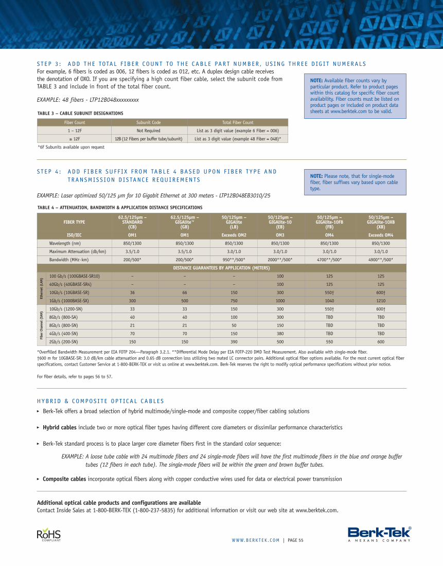
WWW.B ERK T E K . C OM | PAGE 55
S T E P 3 : ADD THE TOTA L F I B E R COUNT TO THE CAB L E PAR T NUMBER , US I NG THR E E D IG I T NUMERA L SFor example, 6 fibers is coded as 006, 12 fibers is coded as 012, etc. A duplex design cable receivesthe denotation of OXO. If you are specifying a high count fiber cable, select the subunit code fromTABLE 3 and include in front of the total fiber count.
EXAMPLE: 48 fibers - LTP12B048xxxxxxxxx
S T E P 4 : ADD F I B E R SU F F I X F ROM TAB L E 4 BAS ED UPON F I B E R T Y P E ANDTRANSM IS S ION D IS TANC E R EQU I R EMEN TS
EXAMPLE: Laser optimized 50/125 µm for 10 Gigabit Ethernet at 300 meters - LTP12B048EB3010/25
Fiber Count Subunit Code Total Fiber Count
1 – 12F Not Required List as 3 digit value (example 6 Fiber = 006)
≥ 12F 12B(12 Fibers per buffer tube/subunit) List as 3 digit value (example 48 Fiber = 048)*
*6F Subunits available upon request
NOTE: Available fiber counts vary byparticular product. Refer to product pageswithin this catalog for specific fiber countavailability. Fiber counts must be listed onproduct pages or included on product datasheets at www.berktek.com to be valid.
NOTE: Please note, that for single-modefiber, fiber suffixes vary based upon cabletype.
TABLE 4 – ATTENUATION, BANDWIDTH & APPLICATION DISTANCE SPECIFICATIONS
*Overfilled Bandwidth Measurement per EIA FOTP 204—Paragraph 3.2.1. **Differential Mode Delay per EIA FOTP-220 DMD Test Measurement. Also available with single-mode fiber.†600 m for 10GBASE-SR: 3.0 dB/km cable attenuation and 0.65 dB connection loss utilizing two mated LC connector pairs. Additional optical fiber options available. For the most current optical fiberspecifications, contact Customer Service at 1-800-BERK-TEK or visit us online at www.berktek.com. Berk-Tek reserves the right to modify optical performance specifications without prior notice.
For fiber details, refer to pages 56 to 57.
Additional optical cable products and configurations are availableContact Inside Sales at 1-800-BERK-TEK (1-800-237-5835) for additional information or visit our web site at www.berktek.com.
TABLE 3 – CABLE SUBUNIT DESIGNATIONS
HYBR ID & COMPOS I T E OP T IC A L CAB L E S� Berk-Tek offers a broad selection of hybrid multimode/single-mode and composite copper/fiber cabling solutions
� Hybrid cables include two or more optical fiber types having different core diameters or dissimilar performance characteristics
� Berk-Tek standard process is to place larger core diameter fibers first in the standard color sequence:
EXAMPLE: A loose tube cable with 24 multimode fibers and 24 single-mode fibers will have the first multimode fibers in the blue and orange buffertubes (12 fibers in each tube). The single-mode fibers will be within the green and brown buffer tubes.
� Composite cables incorporate optical fibers along with copper conductive wires used for data or electrical power transmission
62.5/125µm – 62.5/125µm – 50/125µm – 50/125µm – 50/125µm – 50/125µm –FIBER TYPE STANDARD GIGAlite™ GIGAlite GIGAlite-10 GIGAlite-10FB GIGAlite-10XB
(CB) (GB) (LB) (EB) (FB) (XB)
ISO/IEC OM1 OM1 Exceeds OM2 OM3 OM4 Exceeds OM4
Wavelength (nm) 850/1300 850/1300 850/1300 850/1300 850/1300 850/1300
Maximum Attenuation (db/km) 3.5/1.0 3.5/1.0 3.0/1.0 3.0/1.0 3.0/1.0 3.0/1.0
Bandwidth (MHz·km) 200/500* 200/500* 950**/500* 2000**/500* 4700**/500* 4900**/500*
DISTANCE GUARANTEES BY APPLICATION (METERS)
100 Gb/s (100GBASE-SR10) – – – 100 125 125
40Gb/s (40GBASE-SR4) – – – 100 125 125
10Gb/s (10GBASE-SR) 36 66 150 300 550† 600†
1Gb/s (1000BASE-SX) 300 500 750 1000 1040 1210
10Gb/s (1200-SN) 33 33 150 300 550† 600†
8Gb/s (800-SA) 40 40 100 300 TBD TBD
8Gb/s (800-SN) 21 21 50 150 TBD TBD
4Gb/s (400-SN) 70 70 150 380 TBD TBD
2Gb/s (200-SN) 150 150 390 500 550 600
Fibe
rCh
anne
l(SA
N)Et
hern
et(L
AN)
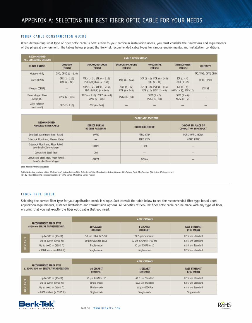
PAGE | WWW.B ERK T E K . C OM56
APPENDIX A: SELECTING THE BEST FIBER OPTIC CABLE FOR YOUR NEEDS
DIRECT BURIAL INDOOR IN PLACE OFRODENT RESISTANT INDOOR/OUTDOOR CONDUIT OR INNERDUCT
Interlock Aluminum, Riser Rated OPRK ATRK, LTRK PDRK, OPRK, HDRK
Interlock Aluminum, Plenum Rated — ATPK, LTPK MDPK, PDPK
Interlock Aluminum, Riser Rated, OPRZK LTRZK —Low-Smoke Zero-Halogen
Corrugated Steel Tape OPA — —
Corrugated Steel Tape, Riser Rated, OPRZA OPRZA —Low-Smoke Zero-Halogen
10 GIGABIT 1 GIGABIT FAST ETHERNETETHERNET ETHERNET (100 Mbps)
Up to 300 m (984 ft) 50 µm GIGAlite™-10 62.5 µm Standard 62.5 µm Standard
Up to 600 m (1968 ft) 50 µm GIGAlite-10XB 50 µm GIGAlite (750 m) 62.5 µm Standard
Up to 1000 m (3280 ft) Single-mode 50 µm GIGAlite-10 62.5 µm Standard
> 1000 meters (>3280 ft) Single-mode Single-mode 62.5 µm Standard
RECOMMENDEDALL-DIELECTRIC DESIGNS CABLE APPLICATIONS
CABLE APPLICATIONS
RECOMMENDED FIBER TYPE(850 nm SERIAL TRANSMISSION)
APPLICATIONS
RECOMMENDEDARMORED FIBER CABLE
DIS
TANCE
Steel Interlock Armor also available
Cable Series Key for above tables: AT—Adventum® Indoor/Outdoor Tight Buffer Loose Tube; LT—Adventum Indoor/Outdoor; OP—Outside Plant; PD—Premises Distribution; IC—Interconnect;RD—12-Fiber Ribbon; MC—Microconnect (for SFF); MD Series—Micro Data Center Plenum
10 GIGABIT 1 GIGABIT FAST ETHERNETETHERNET ETHERNET (100 Mbps)
Up to 300 m (984 ft) 50 µm GIGAlite-10 62.5 µm Standard 62.5 µm Standard
Up to 600 m (1968 ft) Single-mode 62.5 µm Standard 62.5 µm Standard
Up to 2000 m (6560 ft) Single-mode 50 µm GIGAlite 62.5 µm Standard
> 2000 meters (> 6560 ft) Single-mode Single-mode Single-mode
RECOMMENDED FIBER TYPE(1300/1310 nm SERIAL TRANSMISSION)
APPLICATIONS
DIS
TANCE
FLAME RATING OUTDOOR INDOOR/OUTDOOR INDOOR BACKBONE HORIZONTAL INTERCONNECT SPECIALTY(fibers) (fibers) (fibers) (fibers) (fibers)
Outdoor Only OPD, OPDD (2 - 216) — — — — TFC, TFHD, OPTF, OPFD
Riser (OFNR) OPR (2 - 216) ATR (1 - 2), LTR (4 - 216), PDR (6 - 144) ICR (1 - 2), PDR (6 - 144), ICR (1 - 4) OPRF, OPRFTDAR (2 - 12) PDR I/O(BLA) (6 - 144) HDR (2 - 48) MCR (1 - 2)
Plenum (OFNP) — ATP (1 - 2), LTP (4 - 216), MDP (4 - 72) ICP (1 - 2), PDP (6 - 144), ICP (1 - 4) LTP HEPDP HE(BLA) (4 - 144) PDP (6 - 144) RDP (12), HDP (2 - 48) MCP (1 - 2), RDP (12)
Zero-Halogen Riser OPRZ (2 - 216) LTRZ (4 - 216), PDRZ (6 - 48), PDRZ (6 - 48) ICRZ (1 - 2) ICRZ (1 - 4) —(OFNR-LS) OPRZ (2 - 216) PDRZ (6 - 48) MCRZ (1 - 2)
Zero-Halogen OPZ (2 - 216) PDZ (6 - 144) — — — —(not rated)
F I B E R CAB L E CONS T RUC T ION GU ID E
When determining what type of fiber optic cable is best suited to your particular installation needs, you must consider the limitations and requirementsof the physical environment. The tables below present the Berk-Tek recommended cable types for various environmental and installation conditions.
F I B E R T Y P E GU ID E
Selecting the correct fiber type for your application needs is simple. Just consult the table below to see the recommended fiber type based uponapplication requirements, distance limitations and transmission options. All varieties of Berk-Tek fiber optic cable can be made with any type of fiber,ensuring that you get exactly the fiber optic cable that you need.
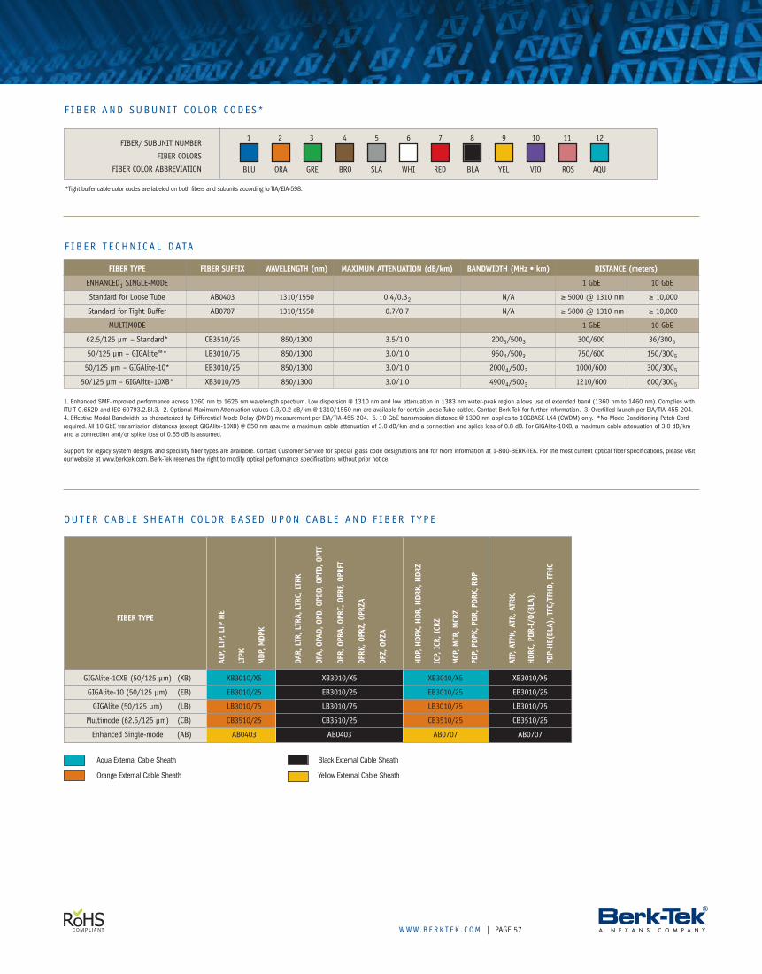
WWW.B ERK T E K . C OM | PAGE 57
F I B E R T E CHN ICA L DATA
1. Enhanced SMF-improved performance across 1260 nm to 1625 nm wavelength spectrum. Low dispersion @ 1310 nm and low attenuation in 1383 nm water-peak region allows use of extended band (1360 nm to 1460 nm). Complies withITU-T G.652D and IEC 60793.2.BI.3. 2. Optional Maximum Attenuation values 0.3/0.2 dB/km @ 1310/1550 nm are available for certain Loose Tube cables. Contact Berk-Tek for further information. 3. Overfilled launch per EIA/TIA-455-204.4. Effective Modal Bandwidth as characterized by Differential Mode Delay (DMD) measurement per EIA/TIA-455-204. 5. 10 GbE transmission distance @ 1300 nm applies to 10GBASE-LX4 (CWDM) only. *No Mode Conditioning Patch Cordrequired. All 10 GbE transmission distances (except GIGAlite-10XB) @ 850 nm assume a maximum cable attenuation of 3.0 dB/km and a connection and splice loss of 0.8 dB. For GIGAlite-10XB, a maximum cable attenuation of 3.0 dB/kmand a connection and/or splice loss of 0.65 dB is assumed.
Support for legacy system designs and specialty fiber types are available. Contact Customer Service for special glass code designations and for more information at 1-800-BERK-TEK. For the most current optical fiber specifications, please visitour website at www.berktek.com. Berk-Tek reserves the right to modify optical performance specifications without prior notice.
*Tight buffer cable color codes are labeled on both fibers and subunits according to TIA/EIA-598.
FIBER/ SUBUNIT NUMBER
FIBER COLORS
FIBER COLOR ABBREVIATION
1 2 3 4 5 6 7 8 9 10 11 12
F I B E R AND SUBUN I T CO LOR CODE S *
FIBER TYPE FIBER SUFFIX WAVELENGTH (nm) MAXIMUM ATTENUATION (dB/km) BANDWIDTH (MHz • km) DISTANCE (meters)
ENHANCED1 SINGLE-MODE 1 GbE 10 GbE
Standard for Loose Tube AB0403 1310/1550 0.4/0.32 N/A ≥ 5000 @ 1310 nm ≥ 10,000
Standard for Tight Buffer AB0707 1310/1550 0.7/0.7 N/A ≥ 5000 @ 1310 nm ≥ 10,000
MULTIMODE 1 GbE 10 GbE
62.5/125 µm – Standard* CB3510/25 850/1300 3.5/1.0 2003/5003 300/600 36/3005
50/125 µm – GIGAlite™* LB3010/75 850/1300 3.0/1.0 9504/5003 750/600 150/3005
50/125 µm – GIGAlite-10* EB3010/25 850/1300 3.0/1.0 20004/5003 1000/600 300/3005
50/125 µm – GIGAlite-10XB* XB3010/X5 850/1300 3.0/1.0 49004/5003 1210/600 600/3005
ACP,
LTP,
LTP
HE
LTPK
MDP
,MDP
K
DAR,
LTR,
LTRA
,LTR
C,LT
RK
OPA,
OPAD
,OPD
,OPD
D,OP
FD,O
PTF
OPR,
OPRA
,OPR
C,OP
RF,O
PRFT
OPRK
,OPR
Z,OP
RZA
OPZ,
OPZA
HDP,
HDPK
,HDR
,HDR
K,HD
RZ
ICP,
ICR,
ICRZ
MCP
,MCR
,MCR
Z
PDP,
PDPK
,PDR
,PDR
K,RD
P
ATP,
ATPK
,ATR
,ATR
K,
HDRC
,PDR
-I/O
(BLA
),
PDP-
HE(B
LA),
TFC/
TFHD
,TFH
C
GIGAlite-10XB (50/125 µm) (XB) XB3010/X5 XB3010/X5 XB3010/X5 XB3010/X5
GIGAlite-10 (50/125 µm) (EB) EB3010/25 EB3010/25 EB3010/25 EB3010/25
GIGAlite (50/125 µm) (LB) LB3010/75 LB3010/75 LB3010/75 LB3010/75
Multimode (62.5/125 µm) (CB) CB3510/25 CB3510/25 CB3510/25 CB3510/25
Enhanced Single-mode (AB) AB0403 AB0403 AB0707 AB0707
FIBER TYPE
OUT ER CAB L E SHEATH CO LOR BAS ED UPON CAB L E AND F I B E R T Y P E
Aqua External Cable Sheath Black External Cable Sheath
Orange External Cable Sheath Yellow External Cable Sheath
BLU ORA GRE BRO SLA WHI RED BLA YEL VIO ROS AQU
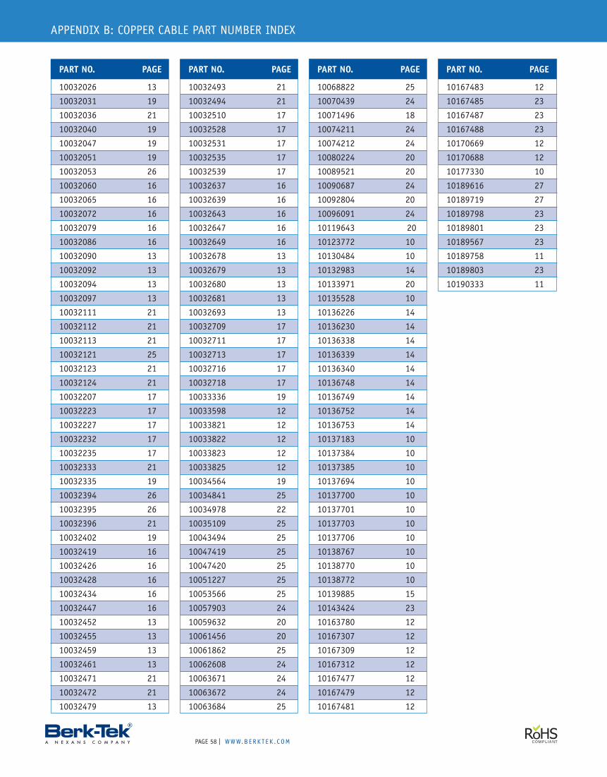
PAGE | WWW.B ERK T E K . C OM58
APPENDIX B: COPPER CABLE PART NUMBER INDEX
10068822 25
10070439 24
10071496 18
10074211 24
10074212 24
10080224 20
10089521 20
10090687 24
10092804 20
10096091 24
10119643 20
10123772 10
10130484 10
10132983 14
10133971 20
10135528 10
10136226 14
10136230 14
10136338 14
10136339 14
10136340 14
10136748 14
10136749 14
10136752 14
10136753 14
10137183 10
10137384 10
10137385 10
10137694 10
10137700 10
10137701 10
10137703 10
10137706 10
10138767 10
10138770 10
10138772 10
10139885 15
10143424 23
10163780 12
10167307 12
10167309 12
10167312 12
10167477 12
10167479 12
10167481 12
10167483 12
10167485 23
10167487 23
10167488 23
10170669 12
10170688 12
10177330 10
10189616 27
10189719 27
10189798 23
10189801 23
10189567 23
10189758 11
10189803 23
10190333 11
PART NO. PAGEPART NO. PAGE PART NO. PAGE PART NO. PAGE
10032493 21
10032494 21
10032510 17
10032528 17
10032531 17
10032535 17
10032539 17
10032637 16
10032639 16
10032643 16
10032647 16
10032649 16
10032678 13
10032679 13
10032680 13
10032681 13
10032693 13
10032709 17
10032711 17
10032713 17
10032716 17
10032718 17
10033336 19
10033598 12
10033821 12
10033822 12
10033823 12
10033825 12
10034564 19
10034841 25
10034978 22
10035109 25
10043494 25
10047419 25
10047420 25
10051227 25
10053566 25
10057903 24
10059632 20
10061456 20
10061862 25
10062608 24
10063671 24
10063672 24
10063684 25
10032026 13
10032031 19
10032036 21
10032040 19
10032047 19
10032051 19
10032053 26
10032060 16
10032065 16
10032072 16
10032079 16
10032086 16
10032090 13
10032092 13
10032094 13
10032097 13
10032111 21
10032112 21
10032113 21
10032121 25
10032123 21
10032124 21
10032207 17
10032223 17
10032227 17
10032232 17
10032235 17
10032333 21
10032335 19
10032394 26
10032395 26
10032396 21
10032402 19
10032419 16
10032426 16
10032428 16
10032434 16
10032447 16
10032452 13
10032455 13
10032459 13
10032461 13
10032471 21
10032472 21
10032479 13
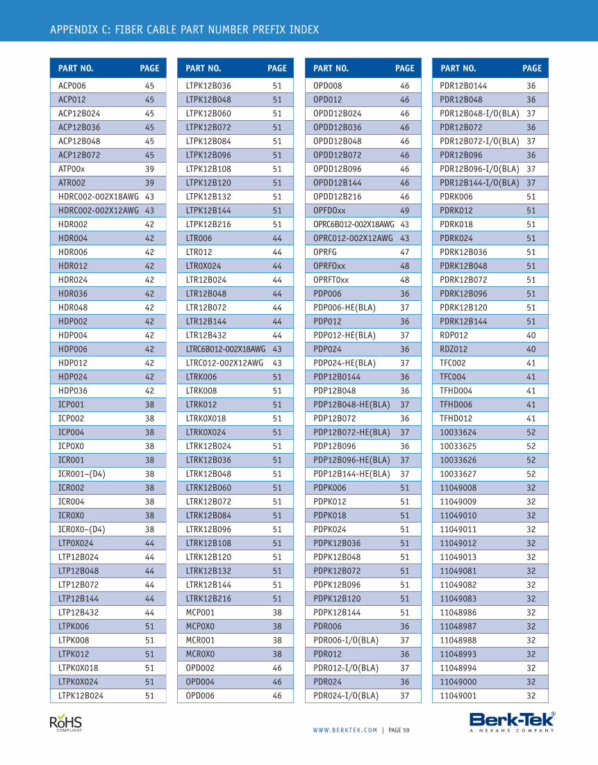
WWW.B ERK T E K . C OM | PAGE 59
APPENDIX C: FIBER CABLE PART NUMBER PREFIX INDEX
ACP006 45
ACP012 45
ACP12B024 45
ACP12B036 45
ACP12B048 45
ACP12B072 45
ATP00x 39
ATR002 39
HDRC002-002X18AWG 43
HDRC002-002X12AWG 43
HDR002 42
HDR004 42
HDR006 42
HDR012 42
HDR024 42
HDR036 42
HDR048 42
HDP002 42
HDP004 42
HDP006 42
HDP012 42
HDP024 42
HDP036 42
ICP001 38
ICP002 38
ICP004 38
ICP0X0 38
ICR001 38
ICR001–(D4) 38
ICR002 38
ICR004 38
ICR0X0 38
ICR0X0–(D4) 38
LTP0X024 44
LTP12B024 44
LTP12B048 44
LTP12B072 44
LTP12B144 44
LTP12B432 44
LTPK006 51
LTPK008 51
LTPK012 51
LTPK0X018 51
LTPK0X024 51
LTPK12B024 51
LTPK12B036 51
LTPK12B048 51
LTPK12B060 51
LTPK12B072 51
LTPK12B084 51
LTPK12B096 51
LTPK12B108 51
LTPK12B120 51
LTPK12B132 51
LTPK12B144 51
LTPK12B216 51
LTR006 44
LTR012 44
LTR0X024 44
LTR12B024 44
LTR12B048 44
LTR12B072 44
LTR12B144 44
LTR12B432 44
LTRC6B012-002X18AWG 43
LTRC012-002X12AWG 43
LTRK006 51
LTRK008 51
LTRK012 51
LTRK0X018 51
LTRK0X024 51
LTRK12B024 51
LTRK12B036 51
LTRK12B048 51
LTRK12B060 51
LTRK12B072 51
LTRK12B084 51
LTRK12B096 51
LTRK12B108 51
LTRK12B120 51
LTRK12B132 51
LTRK12B144 51
LTRK12B216 51
MCP001 38
MCP0X0 38
MCR001 38
MCR0X0 38
OPD002 46
OPD004 46
OPD006 46
OPD008 46
OPD012 46
OPDD12B024 46
OPDD12B036 46
OPDD12B048 46
OPDD12B072 46
OPDD12B096 46
OPDD12B144 46
OPDD12B216 46
OPFDOxx 49
OPRC6B012-002X18AWG 43
OPRC012-002X12AWG 43
OPRFG 47
OPRFOxx 48
OPRFT0xx 48
PDP006 36
PDP006-HE(BLA) 37
PDP012 36
PDP012-HE(BLA) 37
PDP024 36
PDP024-HE(BLA) 37
PDP12B0144 36
PDP12B048 36
PDP12B048-HE(BLA) 37
PDP12B072 36
PDP12B072-HE(BLA) 37
PDP12B096 36
PDP12B096-HE(BLA) 37
PDP12B144-HE(BLA) 37
PDPK006 51
PDPK012 51
PDPK018 51
PDPK024 51
PDPK12B036 51
PDPK12B048 51
PDPK12B072 51
PDPK12B096 51
PDPK12B120 51
PDPK12B144 51
PDR006 36
PDR006-I/O(BLA) 37
PDR012 36
PDR012-I/O(BLA) 37
PDR024 36
PDR024-I/O(BLA) 37
PDR12B0144 36
PDR12B048 36
PDR12B048-I/O(BLA) 37
PDR12B072 36
PDR12B072-I/O(BLA) 37
PDR12B096 36
PDR12B096-I/O(BLA) 37
PDR12B144-I/O(BLA) 37
PDRK006 51
PDRK012 51
PDRK018 51
PDRK024 51
PDRK12B036 51
PDRK12B048 51
PDRK12B072 51
PDRK12B096 51
PDRK12B120 51
PDRK12B144 51
RDP012 40
RDZ012 40
TFC002 41
TFC004 41
TFHD004 41
TFHD006 41
TFHD012 41
10033624 52
10033625 52
10033626 52
10033627 52
11049008 32
11049009 32
11049010 32
11049011 32
11049012 32
11049013 32
11049081 32
11049082 32
11049083 32
11048986 32
11048987 32
11048988 32
11048993 32
11048994 32
11049000 32
11049001 32
PART NO. PAGEPART NO. PAGE PART NO. PAGEPART NO. PAGE
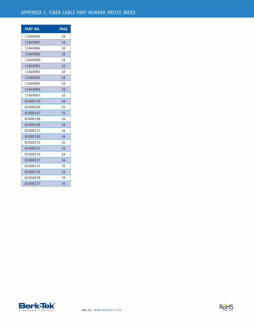
PAGE | WWW.B ERK T E K . C OM60
PART NO. PAGE
11049002 32
11049007 32
11049084 32
11049085 32
11049090 32
11049091 32
11049092 32
11049093 32
11049094 32
11049096 32
11049097 32
81000170 34
81000166 34
81000167 34
81000168 34
81000169 34
81000173 34
81000190 34
81000172 34
81000215 34
81000216 34
81000217 34
81000174 35
81000176 35
81000218 35
81000177 35
APPENDIX C: FIBER CABLE PART NUMBER PREFIX INDEX
B E C A U S E Y O U R B U S I N E S S R U N S T H R O U G H U S
BERK-TEK PRODUCT CATALOG
BER
K-TEK
PRODUCT
CATALO
G
Corporate Headquarters132 White Oak RoadNew Holland, PA 17557USATEL: 717-354-6200TEL: 800-237-5835FAX: 717-354-7944www.berktek.com
In Canada, please contact:Nexans Canada Inc.140 Allstate ParkwayMarkham, OntarioL3R 0Z7 CanadaTEL: 905-944-4300TEL: 800-237-5835FAX: 905-944-4390www.berktek.com
BTPRDCTCTLG 01/11
The world’s highest performing network cables have Berk-Tek written all over them.