Product 42C,D,S,V Series Data Fan Coil Air Conditioners · Carrier’s extensive range of superior...
122
Copyright 2009 Carrier Corporation Form 42-4PD Carrier’s 42C,D,S,V Series fan-coil units offer: • Design flexibility, occupying minimum space • Easy, low-cost installation • Permanent split capacitor motors deliver peak opperating efficiency • High performance, low cost • Greater zone comfort control Features/Benefits Carrier’s extensive range of superior fan-coil units combine design flexibility with easy, low-cost installation. Versatility With Carrier’s 42 Series fan coils, you can select from 5 horizontal, 6 ver- tical, 5 ducted or 3 stacked models; furred-in or cabinet style, slant top or low silhouette, in 150 through 2000 cfm capacities. Coils are available with 1, 2, 3, 4, or 5 rows (depending on model), to satisfy a variety of applica- tion requirements. The units are ideal for installation in motels, apartments, and other multi-room buildings. Many optional control packages are available, including 2-pipe heating and cooling, 2-pipe heating and cooling with auxilia- ry electric heat, 2-pipe cooling with to- tal electric heat, and 4-pipe heating and cooling. Also offered are manual and automatic changeover controls and sev- eral thermostats. Casings and frame are fabricated from tough, heavy gage galvanized steel. Op- tional decorative colors allow the unit to blend with any interior design. 42C,D,S,V Series Fan Coil Air Conditioners 50/60 Hz 150 to 2000 cfm Product Data 42CA HORIZONTAL 42DA DUCTED 42VB VERTICAL 42SH STACK
Transcript of Product 42C,D,S,V Series Data Fan Coil Air Conditioners · Carrier’s extensive range of superior...
Copyright 2009 Carrier Corporation Form 42-4PD
Carrier’s 42C,D,S,V Series fan-coil units offer:• Design flexibility, occupying minimum
space• Easy, low-cost installation• Permanent split capacitor motors
deliver peak opperating efficiency• High performance, low cost• Greater zone comfort control
Features/BenefitsCarrier’s extensive range of superior fan-coil units combine design flexibility with easy, low-cost installation.Versatility
With Carrier’s 42 Series fan coils, you can select from 5 horizontal, 6 ver-tical, 5 ducted or 3 stacked models; furred-in or cabinet style, slant top or low silhouette, in 150 through 2000 cfm capacities. Coils are available with 1, 2, 3, 4, or 5 rows (depending on model), to satisfy a variety of applica-tion requirements. The units are ideal for installation in motels, apartments, and other multi-room buildings. Many optional control packages are available, including 2-pipe heating and cooling, 2-pipe heating and cooling with auxilia-ry electric heat, 2-pipe cooling with to-tal electric heat, and 4-pipe heating and cooling. Also offered are manual and automatic changeover controls and sev-eral thermostats.
Casings and frame are fabricated from tough, heavy gage galvanized steel. Op-tional decorative colors allow the unit to blend with any interior design.
42C,D,S,V SeriesFan Coil
Air Conditioners50/60 Hz
150 to 2000 cfm
ProductData
42CA HORIZONTAL
42DA DUCTED
42VB VERTICAL42SH STACK
2
Low-cost installation and operationEach unit is designed to occupy aminimum space. No complex system controls are required for Carrier fan coil units. Piping, drain, and wiring connections are readily accessible and mounting holes and slots are pre-drilled to save installation time and field labor expense.
42 Series quality reduces service and maintenance expensesCondensate drain pan is heavy gage galvanized steel with closed-cell, fire re-tardant foam insulation. Units come standard with Tuf-Skin® II insulation for energy savings, sound absorption and indoor air quality (IAQ) preserva-tion. Water never touches the pan, so corrosion is minimized and long, trouble-free life is assured.
Efficient operationAll units use permanent split capacitor motors for minimum electrical con-sumption. Blower wheels are centrifugal-type, forward curved, double width, and double inlet sized for maximum efficiency.
Quiet, dependableperformanceAll units are built to operate unobtru-sively with quiet motors and fans. In ad-dition, 1/2-in. thick sound-absorbing, multi-density, matt faced, neoprene-coated fiberglass insulation is used to line the cabinet.
42C Series horizontal, 42VSeries vertical unitsCarrier room fan-coil units operate at exceptionally low sound levels. A generous amount of insulation absorbsoperating sound and rugged, rigid
construction ensures vibration free op-eration at all fan speeds.
Economical, three-speed fans deliver just the right amount of conditioned air for your comfort needs at any load, and each unit can be shut off when not in use. Permanent split capacitor mo-tors deliver peak operating efficiency. By choosing Carrier units, you can match your application with a wide range of custom-designed options and accessories, including electric heat. Fil-ters are cleanable or throwaway type.
Motor bearings are heavy-duty sleeve type, with oversize oil reservoirs to assure long bearing life. All coils are factory leak-tested at 350 psig mini-mum air pressure.
Carrier room fan-coil units provide unsurpassed year-round comfort, with heating and cooling performance certified in compliance with ARI (Air Conditioning & Refrigeration Institute) 440.
Features/Benefits (cont)
Table of contentsPage
Features/Benefits. . . . . . . . . . . . . . . . . . . . . . . . . . . . . . . . . . . . . . . . . . .1-7Options and Accessories. . . . . . . . . . . . . . . . . . . . . . . . . . . . . . . . . . . . .8-10Controls . . . . . . . . . . . . . . . . . . . . . . . . . . . . . . . . . . . . . . . . . . . . . . .11-13Application Data . . . . . . . . . . . . . . . . . . . . . . . . . . . . . . . . . . . . . . . . .14-27Selection Procedure . . . . . . . . . . . . . . . . . . . . . . . . . . . . . . . . . . . . . . . . . 2842C,V Model Number Nomenclature. . . . . . . . . . . . . . . . . . . . . . . . . . . . . . . . 29 ARI Capacity Ratings . . . . . . . . . . . . . . . . . . . . . . . . . . . . . . . . . . 30-32 Physical Data . . . . . . . . . . . . . . . . . . . . . . . . . . . . . . . . . . . . . . . . . . . 33 Base Unit Dimensions . . . . . . . . . . . . . . . . . . . . . . . . . . . . . . . . . . .34-51
Accessory Dimensions . . . . . . . . . . . . . . . . . . . . . . . . . . . . . . . . . . .52-56 Performance Data. . . . . . . . . . . . . . . . . . . . . . . . . . . . . . . . . . . . . .57-71 Electrical Data . . . . . . . . . . . . . . . . . . . . . . . . . . . . . . . . . . . . . . . .72-7442D Model Number Nomenclature. . . . . . . . . . . . . . . . . . . . . . . . . . . . . . . . 75 ARI Capacity Ratings . . . . . . . . . . . . . . . . . . . . . . . . . . . . . . . . . . 75,76 Physical Data . . . . . . . . . . . . . . . . . . . . . . . . . . . . . . . . . . . . . . . . . . . 76 Base Unit Dimensions . . . . . . . . . . . . . . . . . . . . . . . . . . . . . . . . . . .77-81 Accessory Dimensions . . . . . . . . . . . . . . . . . . . . . . . . . . . . . . . . . . .82,83 Performance Data. . . . . . . . . . . . . . . . . . . . . . . . . . . . . . . . . . . . . .84-91 Electrical Data . . . . . . . . . . . . . . . . . . . . . . . . . . . . . . . . . . . . . . . .92-9442S Model Number Nomenclature. . . . . . . . . . . . . . . . . . . . . . . . . . . . . . . . 95 ARI Capacity Ratings . . . . . . . . . . . . . . . . . . . . . . . . . . . . . . . . . . .95,96 Physical Data . . . . . . . . . . . . . . . . . . . . . . . . . . . . . . . . . . . . . . . . . . . 96 Base Unit Dimensions . . . . . . . . . . . . . . . . . . . . . . . . . . . . . . . . . .97-101
Accessory Dimensions . . . . . . . . . . . . . . . . . . . . . . . . . . . . . . . . .102-104 Performance Data. . . . . . . . . . . . . . . . . . . . . . . . . . . . . . . . . . . .105-110 Electrical Data. . . . . . . . . . . . . . . . . . . . . . . . . . . . . . . . . . . . . . . . . . 111Guide Specifications . . . . . . . . . . . . . . . . . . . . . . . . . . . . . . . . . . . . .112-120

3
42D ducted unitsA drip lip (removable drain pan exten-sion) is available for field installation on ceiling models 42DA,DC,DE and DF. The drip lip is recommended for all ceiling models when a valve package is installed.
Motor/blower assembly can be easi-ly removed from the unit for ease of service. Removing this assembly pro-vides clear access to the entering air face of the coil, making coil cleaning a relatively simple matter. Removable panels make access to components and connections easy.
42S stacked unitsEach Carrier stack unit comes factory equipped with insulated supply, return, and drain risers. The design of the 42S units allows them to be set one on top of the other in a vertical column rising floor to floor up the building. Each ris-er has a 3-in. belled section at the top, so the riser piping can be connected by only one sweat connection per riser. Field-installed couplings or internal pipe connections are not needed.
Each stack unit is constructed of 18-gage galvanized steel and factory pre-wired with all control, motor, and optional electric heat wiring conve-niently terminating in a single, accessible junction box. Each stack unit requires only one field power connection.Field-mounted accessories, such as the 3-speed switch/thermostat package for furred-in units, are equipped with a pre-wired quick disconnect plug for easy installation.The riser size for the stack units can be specified to match building require-ments so that cutting, sorting, and han-dling of the risers is not necessary. All units arrive tagged as specified by the customer for efficient delivery to the correct building location.Units can be loaded onto delivery trucks so that they can be off-loaded in the proper installation sequence.The 42SG furred-in-stack is a single unit, designed for concealed applications in corners or along room walls. The return-air grille is removable
to allow access for servicing major components.The 42SG is also available in master/slave unit pairs, shipped individually and installed and piped together in the field. The master unit includes risers with stub out for field piping connec-tions to the slave unit which has no ris-ers of its own.The 42SJ back-to-back furred-in stack is designed for installation in the sepa-ration wall between 2 rooms. The unit consists of 2 units piped to a set of common risers. Each unit has its own valves and controls. The return-air grille is removable to allow access for servicing major components.The 42SH cabinet stack unit is de-signed for applications where con-cealed installations are not possible or practical. This model features a double-deflection supply-air grille and an inte-gral return-air grille access panel. Con-trols are normally mounted on the unit but may also be remote wall mounted.
4
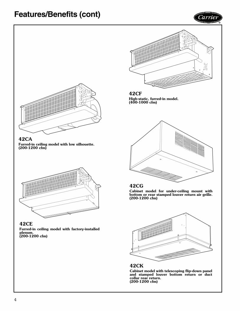
Features/Benefits (cont)
42CAFurred-in ceiling model with low silhouette.(200-1200 cfm)
42CEFurred-in ceiling model with factory-installedplenum.(200-1200 cfm)
42CFHigh-static, furred-in model.(400-1000 cfm)
42CGCabinet model for under-ceiling mount withbottom or rear stamped louver return air grille.(200-1200 cfm)
42CKCabinet model with telescoping flip-down paneland stamped louver bottom return or ductcollar rear return.(200-1200 cfm)

5
42VAFurred-in model for under-the-windowapplications with top or front discharge.(200-1200 cfm)
42VFCabinet model with slant top andtop or front discharge.(200-1200 cfm)
42VCFurred-in lowboy model for concealed under-the-window applications.(200-600 cfm)
42VECabinet lowboy model with stamped louver dis-charge grille and 2 control access doors.(200-600 cfm)
42VGFurred-in wall model. Available with a 10-in.valve compartment extension.(150 and 300 cfm)
42VBCabinet model with top orfront discharge.(200-1200 cfm)
6
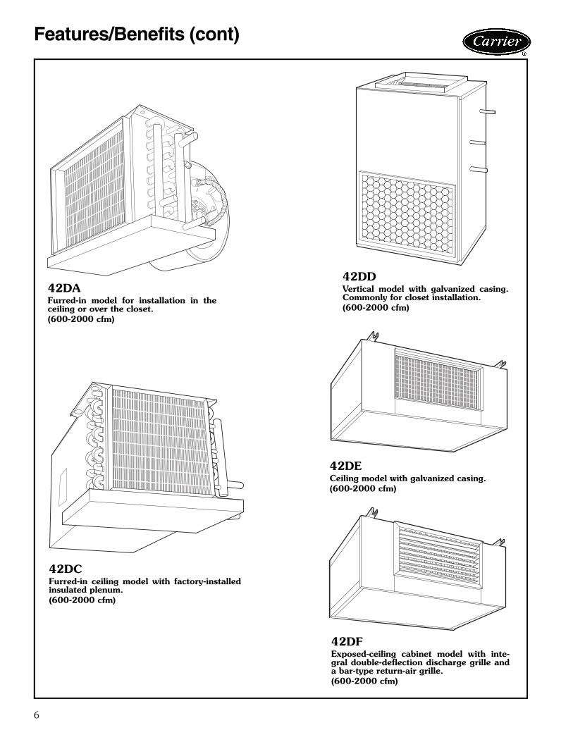
Features/Benefits (cont)
42DAFurred-in model for installation in theceiling or over the closet.(600-2000 cfm)
42DDVertical model with galvanized casing.Commonly for closet installation.(600-2000 cfm)
42DECeiling model with galvanized casing.(600-2000 cfm)
42DFExposed-ceiling cabinet model with inte-gral double-deflection discharge grille anda bar-type return-air grille.(600-2000 cfm)
42DCFurred-in ceiling model with factory-installedinsulated plenum.(600-2000 cfm)

7
42SG — Furred-in-stack(300-1200 cfm)
42SJ — Back-to-backfurred-in stack (300-1200 cfm)
42SH — Cabinet stack(300-1200 cfm)

8
Factory-installed optionsCoils — Choice of a 2-pipe or 4-pipe system with the fol-lowing chilled/hot water coil configurations:
LEGEND
*Needs quote control.
Decorative colors — A wide variety of colors (Cham-pagne Beige, Toffee Brown, Ermine Grey, and PolarWhite) are available to match any interior décor. Select adesired color from a paint chip chart, Catalog number842-011, or provide paint chip for matching. Standardcolor is now Arctic White; the other colors require a specialquote. Optional or custom colors will only be quoted by thefactory if the volume is significant enough to use the mini-mum quantity of paint required by the painting vendor.Therefore, the optional or custom color will not be avail-able on small quantities of units. As an alternative, unitscan be coated with primer by the factory to allow for fieldpainting. Decorative colors may be applied to:• Cabinet of 42VB, VF, VE, VG• Cabinet of 42CG• Panels of 42SH• Bottom panels of 42CK• Wall panels of 42VA• Cabinet of 42DFElectric heaters — Coils are of high grade single-phase,nichrome resistance wire, insulated by ceramic insulators in
plated steel brackets. Heater sizes available are shown inthe application data section for the respective units. Notavailable on 42VG units.Filters — Each unit (except the 42CA, DA unit) includes afiberglass throwaway filter sized for low velocity andmaximum efficiency. The standard option will filter bothreturn and outside-air. Optional permanent aluminum fil-ters with cleanable, non-aluminum filter media are availablefor all 42C Series except 42CA; 42DC, DD, DE; all 42VSeries except 42VG; and all 42S Series units.Manual air vents — Each standard coil includes a man-ual air vent to allow venting at the coil if necessary forquick, complete air elimination.Outside-air opening/damper — Damper is adjustablefrom 0 to 25% and provides ventilation air to unit.(Manual/motorized damper available on 42VA, VB, VFand 42S Series units.)Single power source connection — Provides factory-installed junction box to allow use of single power sourcefor motor and heater when they are of the same voltage.For 42D and 42S Series units.Stamped toe space return-air grille — The return-airgrille is available as a factory-installed option for 42VB and42VF units.Tamperproof Camloc® fasteners — Camloc fastenersare installed on the access panels and are available for allcabinet model units.Thermostat control packages — The standard ther-mostat control option is line voltage. Unit-mounted linevoltage and 24-v thermostats are available on the 42Vseries units. For thermostat control package options referto pages 11-13.
Field-installed accessoriesAutomatic air vents — Automatic air vents have fiberwashers which allow air in the pipes to pass through, auto-matically bleeding the system, and eliminating the need tomanually remove air from the system. When wet, washersswell and seal the system.Decorative wall panels — Wall panels are available foruse with fully recessed 42VA units.Drip lips (removable drain extension) — Drip lips arefrequently used when valves are added after unit installa-tion and space limitations will not permit use of anextended drain pan. The drip lip is placed on the end ofthe drain pan and is pitched toward the pan to ensureproper drainage. The drip lip gives positive control of con-densate from valves and controls. Panels, frames, and grilles — Panels, frames, andgrilles on the 42S Series units can be chosen in a wide vari-ety of combinations to suit room decorating requirementsand allow access to the unit for maintenance. Dischargegrilles are double deflection type, aluminum finish orpainted. Return-air access panels containing return-airgrilles are available in five different types as illustrated onpage 104.
COIL CONFIGURATION
UNIT42C 42D 42S 42V
2-Row Coil42CA,CE,
CG,CK only •
3-Row Coil• • •
42VA,VB, VC,VE,VF
only
4-Row Coil • • • 42VA,VB, VF only
6-Row Coil •
Opposite End Coil Connections
3/1 • • • 42VA,VB, VF only
3/2 • • • 42VA,VB, VF only
4/1 • • • 42VA,VB, VF only
4/2 •
6/142DA,DC,
DE,DF only
6/242DA,DC,
DE,DF only
Same End Coil Connections
2/142VC,VE
only
3/1 • • • 42VA,VB, VF only
3/2 • • • 42VA,VB, VF only
4/1 • • • 42VA,VB, VF only
4/2 •
6/142DA,DC,
DE,DF only
6/242DA,DC,
DE,DF only
Cu/Cu Coil Special Option* • • • •
• — Available in All 42 Series Units
Options and accessories

9
PANELS, FRAMES AND GRILLES
Return-air grilles — Stamped-type return-air grilles arestandard on 42CG,CK,VE,VG, and all S Series units andoptional on 42VB,VF units. Anodized aluminum hingedbar-type grilles are installed on 42DF units.Risers — The 42S Series units can accommodate ¾-in.(supply and return) and 1-in. (drain) to 2½-in. riser sizes in2-pipe systems. For other applications, such as reversereturn risers or 4-pipe systems, it may be necessary toaccommodate the additional risers.Condensate drains are available in sizes down to 1-in. forgreater cost economy. Riser size-reducers are factory-installed and for risers of over 115-in. length, filler piecescan be furnished for field installation.Riser expansion — When necessary, the 42S Seriesunits are provided with factory-installed expansion loops.These expansion loops provide up to 1½-in. of riserexpansion within the standard unit construction. Thismeans that the unit can be used on installations of up to 20floors without any additional expansion devices.Risers material and insulation — The 42S Series unitfactory-installed supply, return, and drain risers can be fur-nished in type M or L copper. All factory-furnished risersare insulated with flexible closed foam insulation in ½-in. or¾-in. thickness.Supply-air grilles — Two types of double deflectionsupply-air grilles are available 42CG, VB, VF, VE units; anintegral steel grille painted to match the unit or a separateunpainted anodized aluminum grille. Standard on 42DFand all 42S Series units.Tell-tale drain pan — A secondary drain connection islocated above the primary drain to act as a “tell-tale” in theevent that the primary drain becomes obstructed. They can
be applied to either the main drain pan or an extendedmain drain pan. This option only available on the 42C and42DA, DC, DE, DF units.Thermostats control packages — The standard ther-mostat control option is line voltage. Wall-mounted linevoltage and 24-v thermostats are available on the 42Series fan coil units. A 24-v thermostat is not available onthe 42VC,VE,VG unit. For thermostat control packagesoptions refer to pages 11-13.Trim strips — Strips are available for use with partiallyrecessed vertical 42VA units and 42S only.Wall boxes — Wall boxes are all aluminum with insectscreen behind louvers. The wall boxes are available on all42V Series units except the 42VG units.
PANELNO. DESCRIPTION
1Standard, 18-gage galvanized steel. Coated with baked-on Arctic White enamel finish. Attached to unit with 1/4 turnfasteners.
218-gage galvanized steel. Coated with baked-on Arctic White enamel finish. Includes access door for concealed unit-mounted controls.
3Bar-type extruded aluminum with frame matching double deflection supply grille. Fastens to wall and unit with 11/2 in. long screws.
4and
5
18-gage galvanized steel. Coated with baked-on Arctic White enamel finish. Frame mounted on sheetrock with screws. Panel mounted in frame with 1/4 turn fasteners.
All Each panel provides access to all internal components.
DRIP LIP(Horizontal Unit)
“TELL-TALE” DRAIN PAN(Horizontal Unit)

10
AVAILABLE OPTIONS AND ACCESSORIES
LEGEND
*Registered trademark of Johns Manville.†Registered trademark of Camloc/RAM.
AVAILABLEFACTORY-INSTALLED OPTIONS AND
FIELD-INSTALLED ACCESSORIES
UNIT SERIES — 42Ceiling — Horizontal Floor — Vertical Ducted — Horizontal Stack — Vertical
CA CE CG CK CF VA VB VF VC VE VG DA DC DE DF DD SG SH SJAIR VENT Automatic Air Vent • • • • • • • • • • • • • • • • • • • Manual Air Vent Std Std Std Std Std Std Std Std Std Std Std Std Std Std Std Std Std Std StdCABINET CHANGES Front Panel, 16 Gage • • Front Panel, 18 Gage Std Std Std Std Std Std Std Std Std Std Std Std Std Std Std Std Std Std Std Extended Cabinet Height • • Valve Compartment Extension, 10 in. • Stamped Toe Space Return Grille • •COILS 2-Row (Cooling Only) • • • • • • • Std Std Std 3-Row (2-Row Cooling, 1-Row Heating) • • 3-Row (Cooling/Heating Only) Std Std Std Std Std Std Std Std • • • • • • • Std Std Std 4-Row (3-Row Cooling, 1-Row Heating) • • • • • • • • • • • • • • • • 4-Row (Cooling/Heating Only) • • • • • • • • Std Std Std Std Std • • • 5-Row (4-Row Cooling, 1-Row Heating) • • • • • • • • • • • • • • • • 5-Row (3-Row Cooling, 2-Row Heating) • • • • • • • • • • • • • • • • 6-Row (4-Row Cooling, 2-Row Heating) • • • • • 6-Row (Cooling/Heating Only) • • • • • 7-Row (6-Row Cooling, 1-Row Heating) • • • • 8-Row (6-Row Cooling, 2-Row Heating) • • • •DAMPERS 25% Manual Damper • • • 25% Motorized Damper • • • 25% Remote Damper • • • 5 x 7 Manual Sliding Damper • • • 4 in. Opening Assembly with Sliding Damper • • • Outdoor Air Connection ETO ETO ETO ETO • • ETO ETO ETO ETODECORATIVE COLORS See Carrier Paint Selector Guide • • • • • • • •DISCHARGE GRILLES Stamped Discharge Std Std Std Std Std Double Deflection, Factory-Installed • • • • Std Double Deflection, Shipped Loose • Std Std StdDRAIN PANS Standard Drain Pan, Closed-Cell Foam on Inside Std Std Std Std Std Std Std Std Std Std Std Std Std Std Std Std Std Std Extended Drain Pan • • • • • Stainless Steel Standard Drain Pan • • • • • • • • • • • • • • • • • • • Stainless Steel Extended Drain Pan • • • • • Tell-Tale Only • • • • • • • • • Drip Lip Only • • • • • • • • • Tell-Tell and Drip Lip • • • • • • • • •DUCT COLLAR Discharge Std Std Std Std Std Std Std Std Std Std Std Std StdELECTRIC HEATERS Nichrome Wire Strip Heater • • • • • • • • • • • • • Sheath Type Heater • • • • •FAN SWITCH Unit-Mounted, Wired and Factory-Installed Std Std Std Std Std Std Wall-Mounted with Plate, Field-Installed Std Std Std Std Std Std Std Std Std Std Std Std StdFILTERS Permanent Filter • • • • • • • • • • • • • • • Throwaway Filter Std Std Std Std Std Std Std Std Std Std Std Std Std Std Std Std StdLEVELING LEGS • • • • • •INSULATION Foil Faced Insulation • • • • • • • • • • • • • • • • Tuf-Skin® II Insulation* Std Std Std Std Std Std Std Std Std Std Std Std Std Std Std Std Std Std Std Exact-O-Kote® Insulation* • • • • • • • • • • • • • • • • Closed Cell Insulation • • • • • • • • • • • • • • • •MOTORS 120-1-60, 3-Speed Std Std Std Std Std Std Std Std Std Std Std Std Std Std Std Std Std Std Std 208-1-60, 3-Speed • • • • • • • • • • • • • • • • • • 230-1-60, 3-Speed • • • • • • • • • • • • • • • • • • 277-1-60, 3-Speed • • • • • • • • • • • • • • • • • • 220-1-50, 3-Speed • • • • • • • • • • • • • • • • • •MOTOR QUICK-DISCONNECT PLUG Std Std Std Std Std Std Std Std Std Std Std Std Std Std Std Std Std StdOUTSIDE-AIR WALL BOX • • •RETURN AIR GRILLE, Shipped Loose Stamped Return Grille Std Std • • Std Std Std Std Std Hinged Panel StdTAMPERPROOF LOCKS (Camloc®†) Access Panels Std Std Std Std Std Std Std Std Std Std Control Access Doors • • •VALVE PACKAGES • • • • • • • • • • • • • • • • • • •WALL PANELS (for Recessed Unit) •WIRING PACKAGES • • • • • • • • • • • • • • • • • • •
• — Available as a Factory-Installed Option or a Field-Installed AccessoryETO — Engineering to OrderStd — Standard
Options and accessories (cont)

11
Use the Control Selection Guide table to make sure that allnecessary components are provided for and that the com-ponents are compatible with the required control system.
NOTE: When thermostatic fan control is selected or whenunit outside-air dampers are used, unit-mounted thermo-stats are not recommended as their use will result in poorroom temperature sensing.
CONTROL SELECTION GUIDE
LEGEND
*If system is HEATING-ONLY or COOLING-ONLY, no changeover or bypass is required.NOTE: Unit-mounted thermostats are not recommended with either fan-cycle control or applications with outside-air dampers.
SYSTEM DESCRIPTION THERMOSTATCHANGEOVER
ONSUPPLY PIPE
VALVE FANSWITCH NOTES
2-P
IPE
HE
AT
ING
-CO
OL
ING
*
FanControl(2-Pipe)
Fan manually cycled None None None Standard 3-speed switch
Not recommendedfor high humidityapplicationThermostat cycles fan on-off
from speed set with fan switch.
Wall mounted includes heat-cool switch.
None None Thermostat has integral 3-Speed Switch
Thermostat cycles fan on-offfrom fan speed set with switch. Mode automatically switched by changeover sensing water temp.
Wall mounted.Heating/coolingThermostat
Yes None Standard3-speed switch
Unit-mounted thermo-stats provide very poor room temperature control
Thermostat cycles fan from high to low on cooling and low to off on heating.
Wall or unit mounted
Yes None No Standard 3-speed switch, ON-OFF toggle switch only
Best fan cycle control for high humidity applications
Two-positionelectricvalves(2-pipe)
Thermostat cycles valveopen or closed.
Wall mounted includes heat-cool switch.
None Motorized (N.C.)3-way or 2-way,no bypass required.
Thermostat has integral 3-speed switch
Valve packages with belled end(s) for field soldering to coil.
Thermostat cycles valveopen or closed. Mode auto-matically switched by changeover sensing water temp.
Wall or unit mounted.Heating/coolingThermostat
Yes Motorized (N.C.)3-way or 2-way
Standard 3-Speed SW. Others have thermostats with integral 3-speed switch
EL
EC
TR
IC H
EA
T
Two-positionelectricvalve withAuxiliaryElectricHeat(2-pipe)
Thermostat cycles valveopen or closed. 2° F aftervalve closes, thermostatactivates electric heater.Heater cannot turn on if hot water is in coil.
Wall or unit mounted. Sequenced heating and cooling.
Yes.Two Required.
Motorized 3-way or 2-way
Standard 3-Speed SW. Others have thermostats with integral 3-speed switch
Valve packages with belled end(s) for field soldering to coil.
Thermostat cycles valveopen or closed. Manualchangeover switch changes thermostat to heat to acti-vate electric heater.
Wall mountedincludes heat-coolswitch.
None Motorized 3-way or 2-way, no bypass required
Thermostat has integral 3-speed switch
Valve packages with belled end(s) for field soldering to coil.
Two-positionelectricvalve withtotalelectricheat(2-pipe)
Thermostat cycles valveopen or closed. Manual changeover switch changes thermostat to heat to acti-vate electric heater.
Wall mounted includes heat-cool switch.
None Motorized (N.C.)3-way or 2-way,no bypass required
Thermostat has integral 3-speed switch
Valve packages with belled end(s) for field soldering to coil.
Thermostat cycles valveopen or closed. 2° F after valve closes, thermostat activates electric heater.
Wall or unit mounted.Sequenced heatingand cooling
None Motorized (N.C.)3-way or 2-way,no bypass required
Standard 3-speed switch
4-P
IPE
Two-positionelectricvalves(4-pipe)
Thermostat cycles cooling and heating valves open or closed.
Wall mounted includes subbase with heat-cool switch.
None Motorized (N.C.)3-way or 2-way(requires 2 valves)
Thermostat has integral 3-speed switch
Valve packages with belled end(s) for field soldering to coil.
Thermostat cycles cooling valve open or closed. 2° F after valve closes, thermo-stat cycles heating valve open or closed.
Wall or unit mounted.Sequenced heatingand cooling.
None Motorized (N.C.)3-way or 2-way(requires 2 valves)
Standard 3-Speed SW. Others havethermostats with integral 3-speed switch
N.C.— Normally Closed
Controls

12
Remote-mounted controls
Standard 3-speed switch — This standard switch has 4positions: OFF, HIGH, MEDIUM, and LOW. Switch hasauxiliary contact that is energized when switch is in HIGH,MEDIUM or LOW position.Some of the options common with the 3-speed switch are:1. Unit-mounted switch on Furred-In Vertical Model.
(Available as special order on Horizontal Models)2. Switch without OFF position.3. Key-operated switch.
Standard remote-mounted thermostat or optional unit-mounted thermostat
24-V Debonair thermostat — Features large Thermo-glow™ display, Neverlost™ memory, ExactFit lockingcover, Smart Fan™ dynamic fan speed control, 4-pipe,2-pipe automatic changeover applications with adjustabledead band. Programmable and non-programmable modelsavailable.
Optional remote-mounted thermostat
Line voltage T155 thermostat — Features 50 to 90 Ftemperature range, manual 3-speed fan control, mount is astandard 2 x 4 in. box, 4-pipe, 2-pipe and autochangeoverapplications. Available in vertical or horizontal styles.Unit-mounted controls
Standard 3-speed switch — Switch has OFF, HIGH,MED and LOW positions. Switch is also equipped withauxiliary connection energized when switch is in HIGH,MED or LOW position.
Combination thermostat/3-speed switch — Includesthermostat for 2-pipe or 4-pipe system and standard3-speed switch. Thermostat and 3-speed switch are unit-mounted in a common electrical junction box. The specialcombination allows for the fan coil unit to have control forthe valve cycle only. This combination thermostat/3-speedswitch (C17 thermostat) is only available for unit mountedline voltage applications.
Controls (cont)
3-SPEED SWITCH
COOL
HEAT
AUTO
R
24-V DEBONAIR® THERMOSTAT
OFF
HI MED
LO
COMBINATION THERMOSTAT/3-SPEED SWITCH
OFF
HI MED
LO
3-SPEED SWITCH
LINE VOLTAGE T155 THERMOSTAT

13
Four-pipe thermostat, model TH104 — With thisthermostat, heating and cooling are sequenced (automaticchangeover) with 6 degree separation between HEATINGON and COOLING ON. The standard temperature rangeis 60 to 90 F.Two-pipe thermostat, model TF103 — Single-poledouble-throw (SPDT) thermostat has snap action contacts.The standard temperature range is 60 to 90 F.
Automatic changeover (Summer-Winter switch) —The automatic-changeover thermostat is a single-poledouble-throw (SPDT) thermal switch in a moistureproofand dust-proof enclosure. Thermostat mechanism and leadends are hermetically sealed in a polypropylene enclosurewith epoxy resin. Device clamps on coil supply pipe withend snap-on clip.
The set point temperatures are factory set. When watertemperature rises above 80 F (approximately), the thermo-stat switches to the winter cycle. When water temperaturedrops below approximately 70 F, the thermostat switchesto the summer cycle. Switch reset is automatic.
Fan coil control relay board — The fan coil relay boardis used in conjunction with the Debonair thermostat or aCCN fan coil controller to regulate a single-speed or multi-speed fan. The fan coil relay board can also be used to con-nect the fan coil controller to a line voltage valve actuator.
The fan coil relay board is factory shipped as a PC boardwith four 1/2-in. stand-offs attached for field mounting.NOTE: One fan coil relay board is used for each applica-tion. Fan coils with two or more fan motors use a fan coilrelay board for each fan motor. A maximum of three fancoil relay boards can be wired to one fan coil control.
STEMCO416-79
L80 8220
AUTOMATIC CHANGEOVER(Summer-Winter) SWITCH
TWO-PIPE THERMOSTAT
G
G2/(W)
G3/(Y)
COM
FAN
(VALVE)
(COOL)HI
(HEAT)MED
LO
FAN COIL CONTROL RELAY BOARD

14
Basic definitionsUnit hand — When facing the supply air outlet from thefront of the unit (air blowing in your face), your right handwill be the right hand side of the unit and your left hand theleft hand side of the unit.
Same end connection (2 pipe or 4 pipe) — All pipingconnections are on the same end (side) of the unit. Con-trols and electrical connection will be on the end (side)opposite the piping connection.
Standard 2-pipe units will be the same end connection.
Opposite end connection (4-pipe option) — Hotwater (HW) piping connections and electrical will be on theend (side) opposite the chilled water (CW) and drainconnections.
Application data
SAME END CONNECTION
NOTE: Piping determines the hand of the unit.
UNIT HAND
OPPOSITE END CONNECTION
NOTE: Chilled water piping determines the hand of the unit.
15
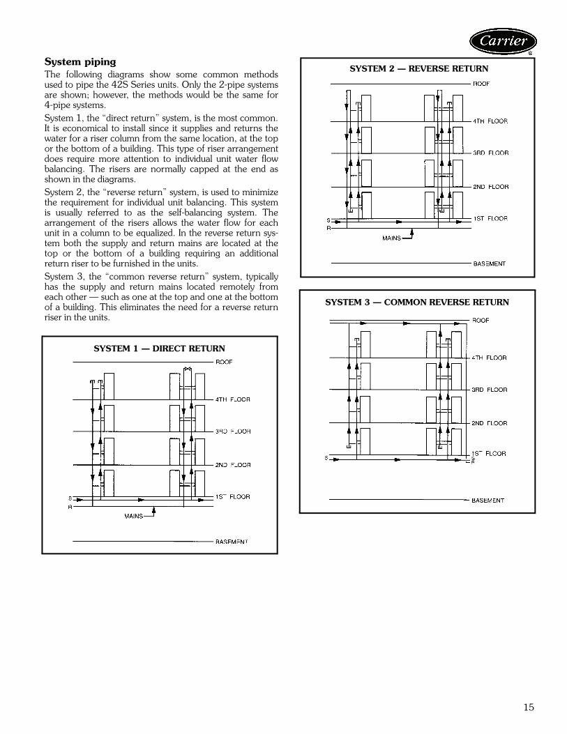
System pipingThe following diagrams show some common methodsused to pipe the 42S Series units. Only the 2-pipe systemsare shown; however, the methods would be the same for4-pipe systems.System 1, the “direct return” system, is the most common.It is economical to install since it supplies and returns thewater for a riser column from the same location, at the topor the bottom of a building. This type of riser arrangementdoes require more attention to individual unit water flowbalancing. The risers are normally capped at the end asshown in the diagrams.System 2, the “reverse return” system, is used to minimizethe requirement for individual unit balancing. This systemis usually referred to as the self-balancing system. Thearrangement of the risers allows the water flow for eachunit in a column to be equalized. In the reverse return sys-tem both the supply and return mains are located at thetop or the bottom of a building requiring an additionalreturn riser to be furnished in the units.System 3, the “common reverse return” system, typicallyhas the supply and return mains located remotely fromeach other — such as one at the top and one at the bottomof a building. This eliminates the need for a reverse returnriser in the units.
SYSTEM 1 — DIRECT RETURN
SYSTEM 2 — REVERSE RETURN
SYSTEM 3 — COMMON REVERSE RETURN
16
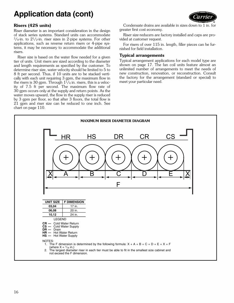
Application data (cont)Risers (42S units)Riser diameter is an important consideration in the designof stack series systems. Standard units can accommodate3/4-in. to 21/2-in. riser sizes in 2-pipe systems. For otherapplications, such as reverse return risers or 4-pipe sys-tems, it may be necessary to accommodate the additionalrisers.
Riser size is based on the water flow needed for a giventier of units. Unit risers are sized according to the diameterand length requirements as specified by the customer. Todetermine riser size, water velocity should be limited to 5 to8 ft per second. Thus, if 10 units are to be stacked verti-cally with each unit requiring 3 gpm, the maximum flow inthe risers is 30 gpm. Through 11/4 in. risers, this is a veloc-ity of 7.5 ft per second. The maximum flow rate of30 gpm occurs only at the supply and return points. As thewater moves upward, the flow in the supply riser is reducedby 3 gpm per floor, so that after 3 floors, the total flow is21 gpm and riser size can be reduced to one inch. Seechart on page 110.
Condensate drains are available in sizes down to 1 in. forgreater first cost economy.
Riser size-reducers are factory installed and caps are pro-vided at customer request.
For risers of over 115 in. length, filler pieces can be fur-nished for field installation.
Typical arrangementsTypical arrangement applications for each model type areshown on page 17. The fan coil units feature almost anunlimited number of arrangements to meet the needs ofnew construction, renovation, or reconstruction. Consultthe factory for the arrangement (standard or special) tomeet your particular need.
MAXIMUM RISER DIAMETER DIAGRAM
LEGEND
NOTES:1. The F dimension is determined by the following formula: X + A + B + C + D + E + X = F
(where X = 7/16 in.)2. The largest diameter riser in each tier must be able to fit in the smallest size cabinet and
not exceed the F dimension.
UNIT SIZE F DIMENSION03,04 17 in.06,08 20 in.10,12 24 in.
CR — Cold Water ReturnCS — Cold Water SupplyDR — DrainHR — Hot Water ReturnHS — Hot Water Supply
a42-3986

17
TYPICAL ARRANGEMENT APPLICATIONS
a42-3987

18
PIPING COMPONENTS
LEGEND
*Check all system component pressure ratings (coils, values, pumps,etc.) with manufacturer and any applicable local or national pipingcodes prior to specifying system pressure rating.
SYMBOL/SKETCH DESCRIPTIONCV FACTOR RATING* STEAM
USE1/2 3/4 PSI FMANUAL AIR VENT: Threaded brass needle valve with screwdriver slot for adjustment.Application — Body brazed into high point of heating and cooling coils for bleeding air from coil. Standard item on all hydronic coils (not used on steam or DX coils). Should not be used in lieu of main system air vents.
N/A N/A 400 100 NO
AUTOMATIC AIR VENT: Nickel plated brass valve, fiber-disc type, with positive shut-off ballcheck and quick vent feature via knurled vent screw.Application — Optional replacement for man-ual air vent. Automatically passes minute quantities of air through the fiber discs which expand upon contact with water, completely sealing the valve. As air accumulates, the fiber discs dry and shrink, repeating the cycle. Not recommended for removing large quantities of air encountered during initial start-up or subse-quent draining and refilling. Should not be used in lieu of main system air vents.
N/A N/A 125 240 NO
SWAGE: Copper tube end expanded to accept a copper tube of the same size for factory or field brazing.Application — Used where possible for all tub-ing joints for best joint integrity.
N/A N/A 300 200 YES
UNION: Combination wrought copper/cast brass union assembly, solder by solder.Application — Used for quick connect (and dis-connect) of valve package components to min-imize field labor and facilitate servicing of unit.
N/A N/A 300 200 YES
INSERTION TEST PORT: Brass body valvefor acceptance of test probe (up to 1/8 in.diameter).Application — Installed on one (or both) sides of the coil to allow for temperature or pressure sensing. Used for close tolerance water bal-ancing and service analysis.
N/A N/A 250 250 NO
Cv — Coefficient of VelocityDX— Direct Expansion
Application data (cont)
19
PIPING COMPONENTS (cont)
LEGEND
SYMBOL/SKETCH DESCRIPTIONCV FACTOR RATING STEAM
USE1/2 3/4 PSI F
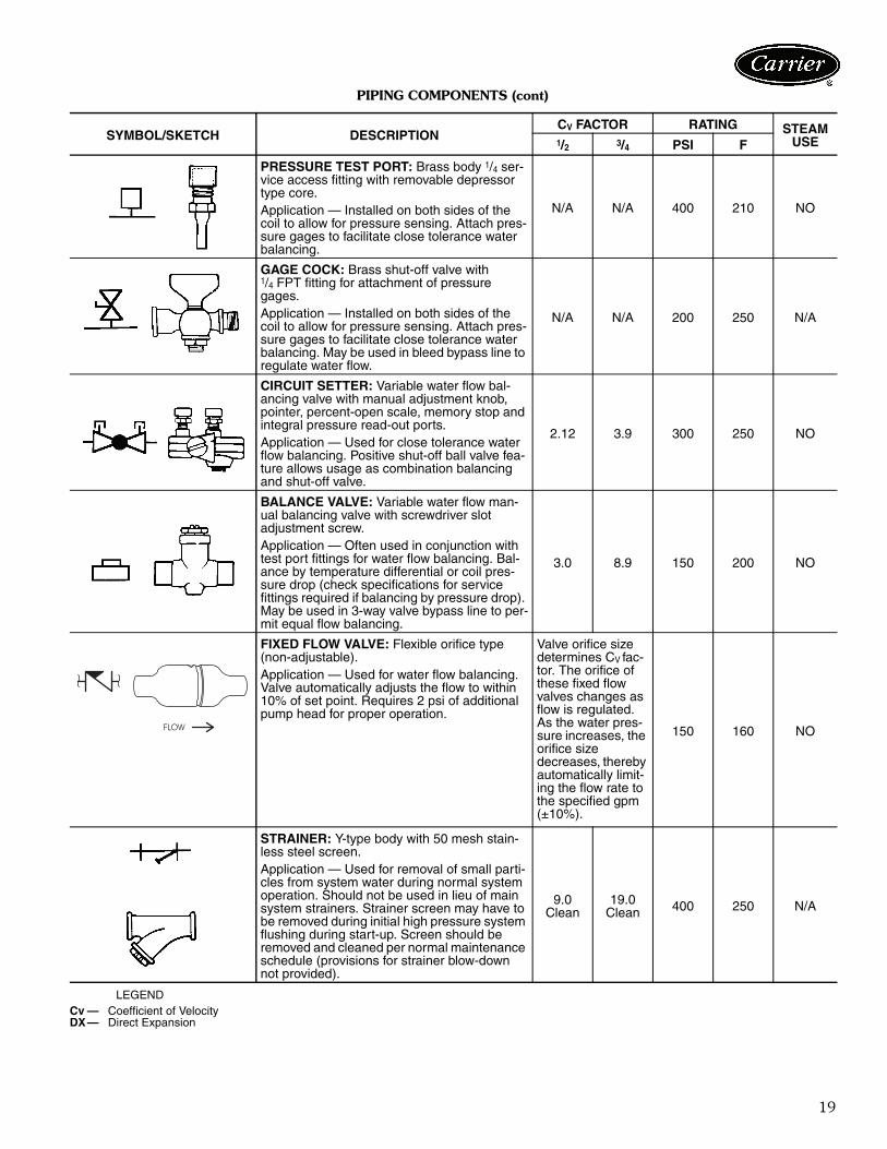
PRESSURE TEST PORT: Brass body 1/4 ser-vice access fitting with removable depressor type core.Application — Installed on both sides of the coil to allow for pressure sensing. Attach pres-sure gages to facilitate close tolerance water balancing.
N/A N/A 400 210 NO
GAGE COCK: Brass shut-off valve with1/4 FPT fitting for attachment of pressure gages.Application — Installed on both sides of the coil to allow for pressure sensing. Attach pres-sure gages to facilitate close tolerance water balancing. May be used in bleed bypass line to regulate water flow.
N/A N/A 200 250 N/A
CIRCUIT SETTER: Variable water flow bal-ancing valve with manual adjustment knob, pointer, percent-open scale, memory stop and integral pressure read-out ports.Application — Used for close tolerance water flow balancing. Positive shut-off ball valve fea-ture allows usage as combination balancing and shut-off valve.
2.12 3.9 300 250 NO
BALANCE VALVE: Variable water flow man-ual balancing valve with screwdriver slot adjustment screw.Application — Often used in conjunction with test port fittings for water flow balancing. Bal-ance by temperature differential or coil pres-sure drop (check specifications for service fittings required if balancing by pressure drop). May be used in 3-way valve bypass line to per-mit equal flow balancing.
3.0 8.9 150 200 NO
FIXED FLOW VALVE: Flexible orifice type (non-adjustable).Application — Used for water flow balancing. Valve automatically adjusts the flow to within 10% of set point. Requires 2 psi of additional pump head for proper operation.
Valve orifice size determines CV fac-tor. The orifice of these fixed flow valves changes as flow is regulated. As the water pres-sure increases, the orifice size decreases, thereby automatically limit-ing the flow rate to the specified gpm (±10%).
150 160 NO
STRAINER: Y-type body with 50 mesh stain-less steel screen.Application — Used for removal of small parti-cles from system water during normal system operation. Should not be used in lieu of main system strainers. Strainer screen may have to be removed during initial high pressure system flushing during start-up. Screen should be removed and cleaned per normal maintenance schedule (provisions for strainer blow-down not provided).
9.0Clean
19.0Clean 400 250 N/A
Cv — Coefficient of VelocityDX— Direct Expansion
����
20
PIPING COMPONENTS (cont)
LEGEND
SYMBOL/SKETCH DESCRIPTIONCV FACTOR RATING STEAM
USE1/2 3/4 PSI F
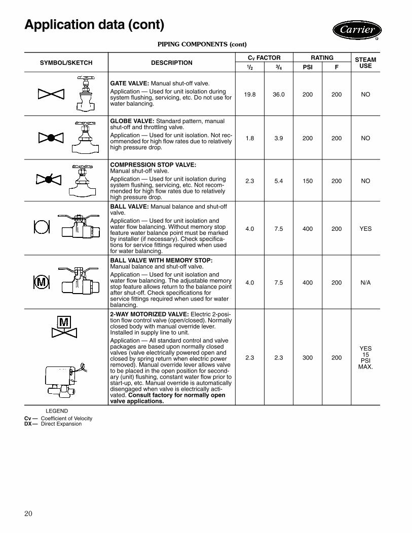
GATE VALVE: Manual shut-off valve.Application — Used for unit isolation during system flushing, servicing, etc. Do not use for water balancing.
19.8 36.0 200 200 NO
GLOBE VALVE: Standard pattern, manual shut-off and throttling valve.Application — Used for unit isolation. Not rec-ommended for high flow rates due to relatively high pressure drop.
1.8 3.9 200 200 NO
COMPRESSION STOP VALVE:Manual shut-off valve.Application — Used for unit isolation during system flushing, servicing, etc. Not recom-mended for high flow rates due to relatively high pressure drop.
2.3 5.4 150 200 NO
BALL VALVE: Manual balance and shut-off valve.Application — Used for unit isolation and water flow balancing. Without memory stop feature water balance point must be marked by installer (if necessary). Check specifica-tions for service fittings required when used for water balancing.
4.0 7.5 400 200 YES
BALL VALVE WITH MEMORY STOP:Manual balance and shut-off valve.Application — Used for unit isolation and water flow balancing. The adjustable memory stop feature allows return to the balance point after shut-off. Check specifications forservice fittings required when used for water balancing.
4.0 7.5 400 200 N/A
2-WAY MOTORIZED VALVE: Electric 2-posi-tion flow control valve (open/closed). Normally closed body with manual override lever. Installed in supply line to unit.Application — All standard control and valve packages are based upon normally closed valves (valve electrically powered open and closed by spring return when electric power removed). Manual override lever allows valve to be placed in the open position for second-ary (unit) flushing, constant water flow prior to start-up, etc. Manual override is automatically disengaged when valve is electrically acti-vated. Consult factory for normally open valve applications.
2.3 2.3 300 200
YES15PSI
MAX.
Cv — Coefficient of VelocityDX— Direct Expansion
Application data (cont)

21
PIPING COMPONENTS (cont)
LEGEND
NOTES:1. Motorized 2-way valves have a maximum close-off differential of 25 psi.2. Motorized 3-way valves have a maximum close-off differential of 10 psi.
SYMBOL/SKETCH DESCRIPTIONCV FACTOR RATING STEAM
USE1/2 3/4 PSI F
3-WAY MOTORIZED VALVE: Electric2-position flow control valve (closed to coil/open to bypass or open to coil/closed to bypass). Normally closed with manual over-ride lever. Installed in supply line to unit.Application — Same comments as 2-way motorized valve except with manual override lever engaged the valve is open to both ports and water flow will take the path of least resis-tance through the valve package (not neces-sarily 100% through the coil).
5.0 5.0
300 200 N/A
SERVICE
2.8 2.8
BYPASS
MODULATING VALVE (Optional)(Non-Spring Return): Modulating valves are designed to control the flow in the circuit by making incremental adjustments to the flow path within the valve. Application — To control fluid flow in fan coil units.On the 42DD,SG,SJ,SH commercial fan coil models, the factory provided modulating valve has application restrictions. In these models, the valve packages are located in the air-stream, downstream of the coil. Due to the ambient temperature limitations of the modu-lating valves, the valves can only be used in the units listed above with 2-pipe cooling only systems.
4.0 300 200 N/A
MODULATING VALVE (Requires ETO)(Spring Return): Modulating valves are designed to control the flow in the circuit by making incremental adjustments to the flow path within the valve.Application — Same comments as non-spring return except when powered, the actuator moves to the desired position, at the same time tensing the spring return system. When power is removed for more than two minutes the spring returns the actuator to the normal position.
4.0 300 200 N/A
AQUASTAT: Water temperature sensing elec-trical switch.Application — Clips directly on nominalsize 1/2 in. or 3/4 in. copper tubing for water temperature sensing. Must be correctly located for proper control operation.
Cv — Coefficient of VelocityDX — Direct ExpansionETO — Engineering to Order
22
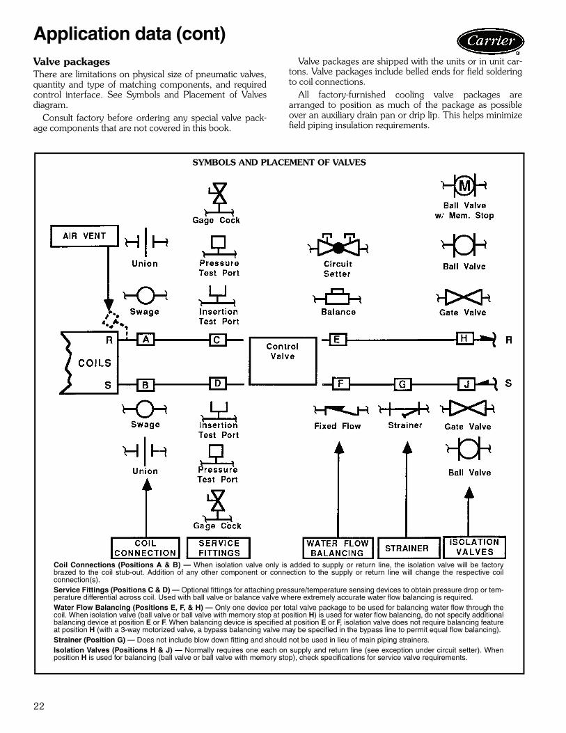
Valve packagesThere are limitations on physical size of pneumatic valves,quantity and type of matching components, and requiredcontrol interface. See Symbols and Placement of Valvesdiagram.
Consult factory before ordering any special valve pack-age components that are not covered in this book.
Valve packages are shipped with the units or in unit car-tons. Valve packages include belled ends for field solderingto coil connections.
All factory-furnished cooling valve packages arearranged to position as much of the package as possibleover an auxiliary drain pan or drip lip. This helps minimizefield piping insulation requirements.
Application data (cont)
SYMBOLS AND PLACEMENT OF VALVES
Coil Connections (Positions A & B) — When isolation valve only is added to supply or return line, the isolation valve will be factorybrazed to the coil stub-out. Addition of any other component or connection to the supply or return line will change the respective coilconnection(s).Service Fittings (Positions C & D) — Optional fittings for attaching pressure/temperature sensing devices to obtain pressure drop or tem-perature differential across coil. Used with ball valve or balance valve where extremely accurate water flow balancing is required.Water Flow Balancing (Positions E, F, & H) — Only one device per total valve package to be used for balancing water flow through thecoil. When isolation valve (ball valve or ball valve with memory stop at position H) is used for water flow balancing, do not specify additionalbalancing device at position E or F. When balancing device is specified at position E or F, isolation valve does not require balancing featureat position H (with a 3-way motorized valve, a bypass balancing valve may be specified in the bypass line to permit equal flow balancing).Strainer (Position G) — Does not include blow down fitting and should not be used in lieu of main piping strainers.Isolation Valves (Positions H & J) — Normally requires one each on supply and return line (see exception under circuit setter). Whenposition H is used for balancing (ball valve or ball valve with memory stop), check specifications for service valve requirements.
a42-213tf

23
VALVE PACKAGE ARRANGEMENTS
a42-3988
LEGEND
*When aquastat is used for automatic changeover, bypass isrequired as indicated by dashed line.
NOTES:1. Packages factory furnished and installed.2. Valves are 5/8-in. ODS unless otherwise specified.3. If an automatic flow control valve is added, it will be located on
supply line between shutoff valve and coil (or motorized controlvalve, if supplied).
4. Packages 17-A,C,D,E,F,J,K,L, and P are listed on current pricepages.
Ball Valve
Ball Valve with Memory Stop
Circuit Setter
Motorized 2-Way Valve
Motorized 3-Way Valve
M
M
M

24
Application data (cont)
CV FACTOR:The flow rate in gallons per minute (gpm) through a piping component when the pressure drop (ΔP) in pounds per square inch (psi)across the component is 1.0 (psi).
Pressure drop (ft-H2O) = 2.31 x psi (pressure drop)
GRAPH EXAMPLE:ΔP for 2.0 gpm through a component with a CV of 1.0 is 4.0 psi x 2.31 = 9.24 ft-H2O
FORMULA EXAMPLE:
TOTAL PRESSURE DROP is the Sum of the pressure drop of all piping and components in the water flow path.
ΔP (ft-H2O) =(gpm)2
x 2.31 =(2.0)2
x 2.31 = 9.24 ft-H2O(Cv)2 (1.0)2
Cv FACTOR VS WATER PRESSURE DROP

25
ENTHALPY AT SATURATION
ALTITUDE COOLING CORRECTION FACTORS STEAM PRESSURE CORRECTION FACTORS
NOTE: Steam Heating Capacity (Btuh) = Base Capacity x PressureCorrection Factor x SH (SH value found in Cooling Capacity CorrectionFactors table on page 68).
AIRFLOW CORRECTION FACTORS
LEGEND
TEMPERATURE(F)
ENTHALPY ATSATURATION
(Btu per lbof dry air)
TEMPERATURE(F)
ENTHALPY ATSATURATION
(Btu per lbof dry air)
40 15.230 60 26.4641 15.697 61 27.1542 16.172 62 27.8543 16.657 63 28.5744 17.149 64 29.3145 17.650 65 30.0646 18.161 66 30.8347 18.680 67 31.6248 19.211 68 32.4249 19.751 69 33.2550 20.301 70 34.0951 20.862 71 34.9552 21.436 72 35.8353 22.020 73 36.7454 22.615 74 37.6655 23.22 75 38.6156 23.84 76 39.5757 24.48 77 40.5758 25.12 78 41.5859 25.78 79 42.62
80 43.69
ELEVATION (ft) TOTAL HEAT SENSIBLE HEATSea Level 1.00 1.00
1000 .990 .9602000 .980 .9303000 .970 .8964000 .960 .8645000 .940 .8306000 .930 .8007000 .920 .7708000 .910 .7509000 .900 .730
ENTERING AIRTEMP (F)
STEAM PRESSURE (PSIG)2 5
40 1.202 1.26550 1.134 1.19660 1.067 1.12570 1.000 1.054
CFM RATIO(Actual/Base) TOTAL (Ct) SENSIBLE (Cs)
1.40 1.25 1.261.35 1.22 1.231.30 1.19 1.201.25 1.16 1.171.20 1.13 1.141.15 1.10 1.111.10 1.07 1.081.05 1.04 1.041.00 1.00 1.000.95 0.97 0.970.90 0.94 0.930.85 0.90 0.890.80 0.86 0.850.75 0.82 0.810.70 0.78 0.770.65 0.74 0.720.60 0.70 0.670.55 0.66 0.620.50 0.62 0.570.45 0.58 0.520.40 0.53 0.470.35 0.48 0.420.30 0.43 0.380.25 0.38 0.33
CFM — Cubic Feet per MinuteCs — Sensible Airflow Correction FactorCt — Total Airflow Correction Factor

26
Electric heatElectric heaters are available for installation on Carrier fancoil units in the following applications.Total electric heat — This system provides completeheating during the heating season; no boiler is required.Heating and cooling are now available on an individualbasis throughout the year with a 2-pipe system.
Chilled water is used for cooling and the electric heater isused for heating. Individual room controls can be suppliedfor either manual or automatic changeover.Auxiliary electric heat — This system is used for heat-ing between seasons or during the cooling season whenchilled water is being circulated. Individual room controlsare supplied to provide electric heat only when chilledwater is being circulated through the system. Water flowthrough the unit is shut off when the heater is turned on.
During the winter heating season, heating is provided byhot water circulated through the system. A changeoverdevice locks out the electric heat when the hot water iscirculated.
Heater constructionStrip heaters are used with Model 42C ceiling units,Model 42D ducted units and Model 42S stack units.
These heaters consist of coils of the highest grade resis-tance wire, insulated by ceramic insulators in aluminizedbrackets.
All heaters except those used in 42S stack units are posi-tioned on the incoming (preheat) side of the unit coil. On
42S stack units, the strip heater is located in the fan dis-charge on the leaving side of the coil.Sheath heaters are used with Model 42V vertical units.These heaters consist of the highest grade resistance wire,centered in a 1/2-in. diameter copper-plated steel sheath.The wire is insulated from the sheath by magnesium oxidepowder packed around it. To increase the heater surfaceexposed to air, a 11/4-in. OD fin of copper-plated steel iswound around the sheath in a continuous spiral that makes5 turns per lineal inch. Sheath and fin are permanentlybonded together by copper brazing.
The heaters are positioned on the leaving (reheat) side ofthe unit coil. On special units with high-efficiency motors, astrip heater will be installed in the fan discharge on theincoming (preheat) side of the unit coil.
Heater electrical data1. Load voltage may be 120, 208, 240 or 277 volts. For
unit size and kW limitations, refer to the specific unitcatalogs.
2. All heaters are single stage and single phase.3. Unless a single power-source option is selected, the
electric heat units require 2 separate power sources.With the single power-source option, only one line cir-cuit need be brought into the unit. Fuse protection isadded to the motor/control circuit to protect thesecomponents. This is separate from the field-furnishedtotal unit overcurrent protection.
Application data (cont)
MODEL 42C CEILING UNITWITH ELECTRIC STRIP HEATER
MODEL 42V VERTICAL UNITWITH ELECTRIC SHEATH HEATER
27
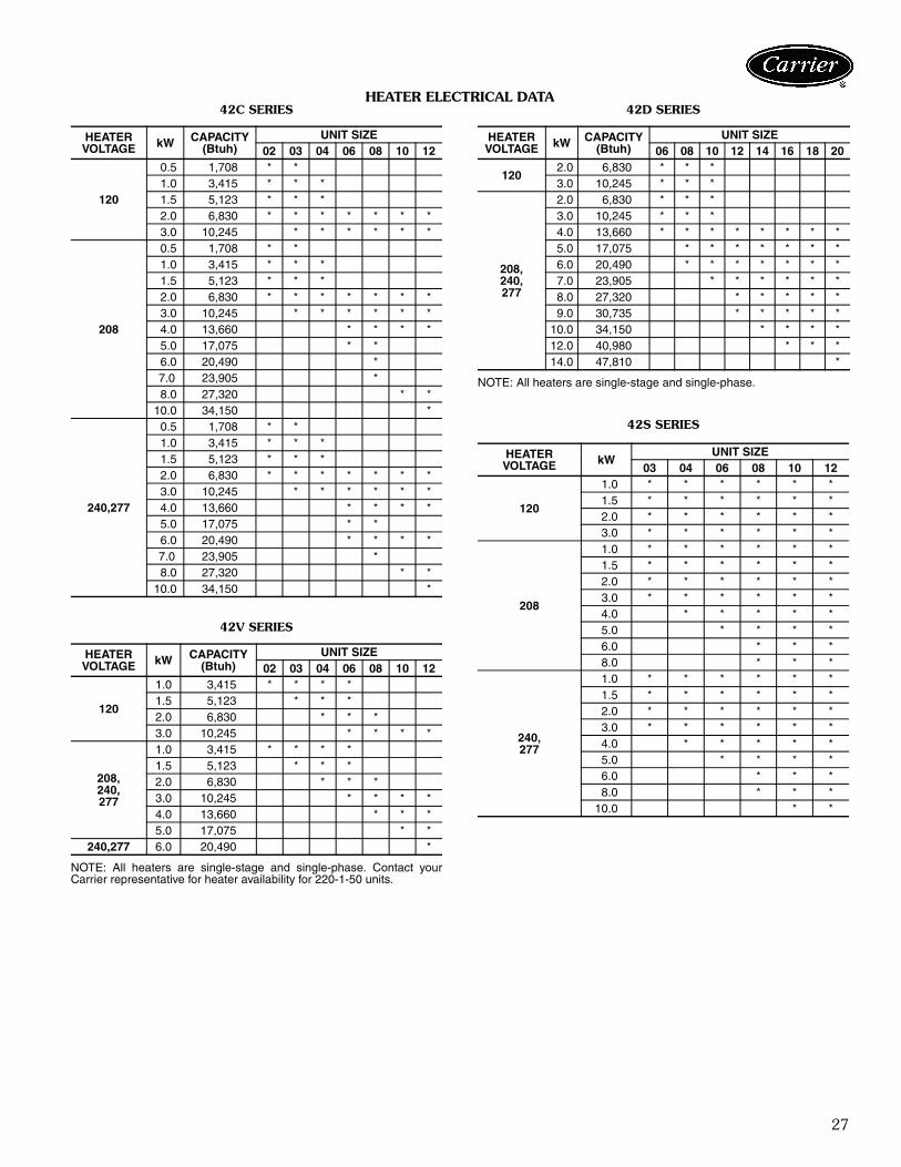
HEATER ELECTRICAL DATA42C SERIES
42V SERIES
NOTE: All heaters are single-stage and single-phase. Contact yourCarrier representative for heater availability for 220-1-50 units.
42D SERIES
NOTE: All heaters are single-stage and single-phase.
42S SERIES
HEATERVOLTAGE kW CAPACITY
(Btuh)UNIT SIZE
02 03 04 06 08 10 12
120
0.5 1,708 * *1.0 3,415 * * *1.5 5,123 * * *2.0 6,830 * * * * * * *3.0 10,245 * * * * * *
208
0.5 1,708 * *1.0 3,415 * * *1.5 5,123 * * *2.0 6,830 * * * * * * *3.0 10,245 * * * * * *4.0 13,660 * * * *5.0 17,075 * *6.0 20,490 *
7.0 23,905 *8.0 27,320 * *
10.0 34,150 *
240,277
0.5 1,708 * *1.0 3,415 * * *1.5 5,123 * * *2.0 6,830 * * * * * * *3.0 10,245 * * * * * *4.0 13,660 * * * *5.0 17,075 * *6.0 20,490 * * * *
7.0 23,905 *8.0 27,320 * *
10.0 34,150 *
HEATERVOLTAGE kW CAPACITY
(Btuh)UNIT SIZE
02 03 04 06 08 10 12
120
1.0 3,415 * * * *1.5 5,123 * * *2.0 6,830 * * *3.0 10,245 * * * *
208,240,277
1.0 3,415 * * * *1.5 5,123 * * *2.0 6,830 * * *3.0 10,245 * * * *4.0 13,660 * * *5.0 17,075 * *
240,277 6.0 20,490 *
HEATERVOLTAGE kW CAPACITY
(Btuh)UNIT SIZE
06 08 10 12 14 16 18 20
1202.0 6,830 * * *3.0 10,245 * * *
208,240,277
2.0 6,830 * * *3.0 10,245 * * *4.0 13,660 * * * * * * * *5.0 17,075 * * * * * * *6.0 20,490 * * * * * * *7.0 23,905 * * * * * *8.0 27,320 * * * * *9.0 30,735 * * * * *
10.0 34,150 * * * *12.0 40,980 * * *14.0 47,810 *
HEATERVOLTAGE kW
UNIT SIZE03 04 06 08 10 12
120
1.0 * * * * * *1.5 * * * * * *2.0 * * * * * *3.0 * * * * * *
208
1.0 * * * * * *1.5 * * * * * *2.0 * * * * * *3.0 * * * * * *4.0 * * * * *5.0 * * * *6.0 * * *8.0 * * *
240,277
1.0 * * * * * *1.5 * * * * * *2.0 * * * * * *3.0 * * * * * *4.0 * * * * *5.0 * * * *6.0 * * *8.0 * * *
10.0 * *
28
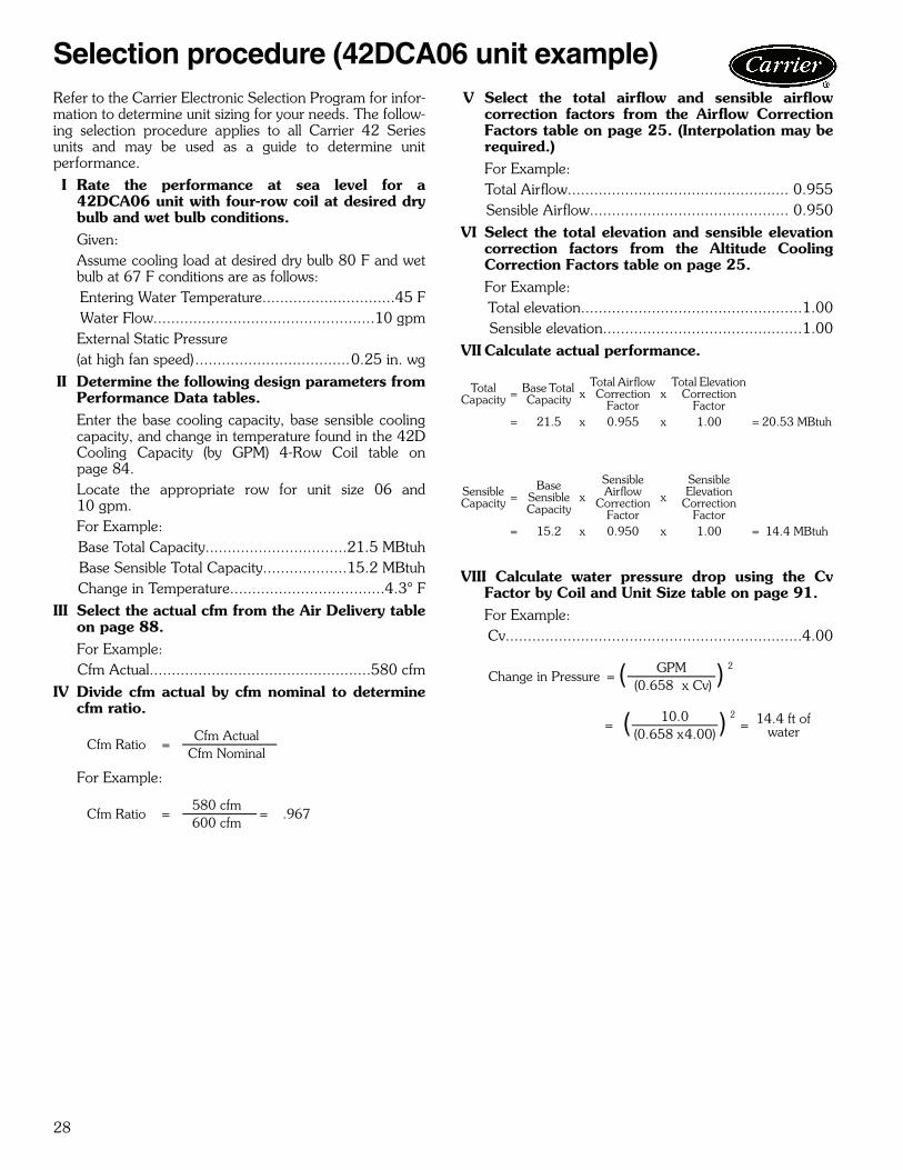
Refer to the Carrier Electronic Selection Program for infor-mation to determine unit sizing for your needs. The follow-ing selection procedure applies to all Carrier 42 Seriesunits and may be used as a guide to determine unitperformance.I Rate the performance at sea level for a
42DCA06 unit with four-row coil at desired drybulb and wet bulb conditions.Given:Assume cooling load at desired dry bulb 80 F and wetbulb at 67 F conditions are as follows:Entering Water Temperature..............................45 FWater Flow..................................................10 gpmExternal Static Pressure(at high fan speed)...................................0.25 in. wg
II Determine the following design parameters fromPerformance Data tables.Enter the base cooling capacity, base sensible coolingcapacity, and change in temperature found in the 42DCooling Capacity (by GPM) 4-Row Coil table onpage 84.Locate the appropriate row for unit size 06 and10 gpm.For Example:Base Total Capacity................................21.5 MBtuhBase Sensible Total Capacity...................15.2 MBtuhChange in Temperature...................................4.3° F
III Select the actual cfm from the Air Delivery tableon page 88.For Example:Cfm Actual..................................................580 cfm
IV Divide cfm actual by cfm nominal to determinecfm ratio.
For Example:
V Select the total airflow and sensible airflowcorrection factors from the Airflow CorrectionFactors table on page 25. (Interpolation may berequired.)For Example:Total Airflow.................................................. 0.955Sensible Airflow............................................. 0.950
VI Select the total elevation and sensible elevationcorrection factors from the Altitude CoolingCorrection Factors table on page 25. For Example:Total elevation..................................................1.00Sensible elevation.............................................1.00
VII Calculate actual performance.
VIII Calculate water pressure drop using the CvFactor by Coil and Unit Size table on page 91.For Example:Cv...................................................................4.00
Cfm Ratio =Cfm Actual
Cfm Nominal
Cfm Ratio =580 cfm
= .967600 cfm
Total Capacity = Base Total
Capacity xTotal Airflow Correction
Factorx
Total Elevation Correction
Factor= 21.5 x 0.955 x 1.00 = 20.53 MBtuh
SensibleCapacity =
Base Sensible Capacity
xSensible Airflow
Correction Factor
xSensibleElevation
Correction Factor
= 15.2 x 0.950 x 1.00 = 14.4 MBtuh
Change in Pressure = ( GPM ) 2
(0.658 x Cv)
= ( 10.0 ) 2= 14.4 ft of
water(0.658 x4.00)
Selection procedure (42DCA06 unit example)

29
Model number nomenclature4
2C
,V S
eries Units
*Model 42CG only.
a42-4098.eps
30
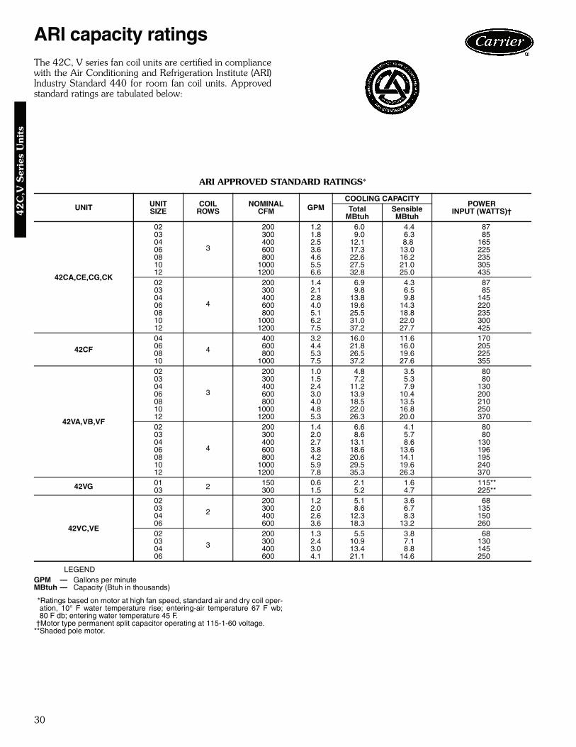
The 42C, V series fan coil units are certified in compliancewith the Air Conditioning and Refrigeration Institute (ARI)Industry Standard 440 for room fan coil units. Approvedstandard ratings are tabulated below:
ARI APPROVED STANDARD RATINGS*
LEGEND
*Ratings based on motor at high fan speed, standard air and dry coil oper-ation, 10° F water temperature rise; entering-air temperature 67 F wb;80 F db; entering water temperature 45 F.
†Motor type permanent split capacitor operating at 115-1-60 voltage.**Shaded pole motor.
UNIT UNITSIZE
COILROWS
NOMINALCFM GPM
COOLING CAPACITYPOWER
INPUT (WATTS)†TotalMBtuh
SensibleMBtuh
42CA,CE,CG,CK
02
3
200 1.2 6.0 4.4 8703 300 1.8 9.0 6.3 8504 400 2.5 12.1 8.8 16506 600 3.6 17.3 13.0 22508 800 4.6 22.6 16.2 23510 1000 5.5 27.5 21.0 30512 1200 6.6 32.8 25.0 43502
4
200 1.4 6.9 4.3 8703 300 2.1 9.8 6.5 8504 400 2.8 13.8 9.8 14506 600 4.0 19.6 14.3 22008 800 5.1 25.5 18.8 23510 1000 6.2 31.0 22.0 30012 1200 7.5 37.2 27.7 425
42CF
04
4
400 3.2 16.0 11.6 17006 600 4.4 21.8 16.0 20508 800 5.3 26.5 19.6 22510 1000 7.5 37.2 27.6 355
42VA,VB,VF
02
3
200 1.0 4.8 3.5 8003 300 1.5 7.2 5.3 8004 400 2.4 11.2 7.9 13006 600 3.0 13.9 10.4 20008 800 4.0 18.5 13.5 21010 1000 4.8 22.0 16.8 25012 1200 5.3 26.3 20.0 37002
4
200 1.4 6.6 4.1 8003 300 2.0 8.6 5.7 8004 400 2.7 13.1 8.6 13006 600 3.8 18.6 13.6 19608 800 4.2 20.6 14.1 19510 1000 5.9 29.5 19.6 24012 1200 7.8 35.3 26.3 370
42VG 01 2 150 0.6 2.1 1.6 115**03 300 1.5 5.2 4.7 225**
42VC,VE
02
2
200 1.2 5.1 3.6 6803 300 2.0 8.6 6.7 13504 400 2.6 12.3 8.3 15006 600 3.6 18.3 13.2 26002
3
200 1.3 5.5 3.8 6803 300 2.4 10.9 7.1 13004 400 3.0 13.4 8.8 14506 600 4.1 21.1 14.6 250
GPM — Gallons per minuteMBtuh — Capacity (Btuh in thousands)
ARI capacity ratings4
2C
,V S
erie
s U
nits

31
SOUND POWER DATA42CA,CG,CE,CK SOUND RATINGS — OCTAVE BAND POWER LEVEL RATINGS* (dB)
*Testing per ARI Standard 350-2000.
42CF SOUND RATINGS — OCTAVE BAND POWER LEVEL RATINGS* (dB)
*Testing per ARI Standard 350-2000.
SIZE NOMINALCFM SPEED RPM
CENTER FREQUENCY — Hz125 250 500 1000 2000 4000 8000
02 200High 1130 59 58 59 57 52 49 46Medium 1060 54 54 55 51 42 42 41Low 940 45 49 51 47 43 37 33
03 300High 1125 61 59 61 58 54 51 47Medium 1025 55 54 54 51 46 42 41Low 925 43 48 49 46 42 36 31
04 400High 1400 62 61 62 59 55 51 46Medium 905 54 54 54 50 46 41 26Low 725 49 48 47 42 34 — —
06 600High 1525 63 62 63 60 56 53 48Medium 1100 55 54 54 51 47 41 31Low 690 51 50 49 44 36 — —
08 800High 1500 66 66 67 64 60 58 53Medium 1045 59 56 59 55 47 42 37Low 675 51 51 50 46 38 — —
10 1000High 1365 73 70 71 68 64 62 58Medium 785 62 60 61 57 51 48 46Low 700 56 56 57 52 46 40 34
12 1200High 1540 78 75 76 73 68 67 63Medium 1155 68 67 68 64 59 56 54Low 740 59 60 60 56 50 43 37
SIZE NOMINAL CFM SPEED RPMCENTER FREQUENCY — Hz
125 250 500 1000 2000 4000 8000
04 400High 1085 62 65 65 63 58 54 47Medium 980 60 62 62 60 56 51 43Low 840 57 59 59 56 51 46 37
06 600High 1075 62 65 65 63 58 54 47Medium 955 60 62 62 60 56 51 43Low 740 57 59 59 56 51 46 37
08 800High 1045 62 65 65 63 58 54 47Medium 865 60 62 62 60 56 51 43Low 715 57 59 59 56 51 46 37
10 1000High 1100 62 65 65 63 58 54 47Medium 1015 60 62 62 60 56 51 43Low 900 57 59 59 56 51 46 37
42
C,V
Series U
nits

32
SOUND POWER DATA (cont)42VA,VB,VF SOUND RATINGS — OCTAVE BAND SOUND POWER LEVEL RATINGS* (dB)
*Testing per ARI Standard 350-2000.
42VC,VE SOUND RATINGS — OCTAVE BAND SOUND POWER LEVEL RATINGS* (dB)
*Testing per ARI Standard 350-2000.
SIZE NOMINAL CFM SPEED RPM
CENTER FREQUENCY — Hz125 250 500 1000 2000 4000 8000
02 200High 1130 63 58 53 46 40 34 25Medium 1090 58 57 51 45 39 32 —Low 1025 61 57 50 44 37 30 —
03 300High 1120 65 60 54 48 42 35 26Medium 1070 60 59 53 47 41 34 —Low 1000 63 59 52 46 39 32 —
04 400High 1520 66 67 64 58 50 45 39Medium 1085 58 60 53 47 40 32 —Low 840 52 55 47 40 33 — —
06 600High 1625 67 68 65 59 53 48 42Medium 1310 61 62 56 52 46 40 —Low 825 54 56 48 41 34 — —
08 800High 1610 68 68 65 60 55 51 44Medium 1300 63 64 59 54 50 45 36Low 820 55 56 49 43 37 28 —
10 1000High 1530 68 69 65 61 54 49 44Medium 1095 66 66 60 56 50 45 38Low 850 58 58 52 46 38 31 —
12 1200High 1625 70 71 67 63 56 51 46Medium 1310 69 69 63 59 53 48 42Low 830 60 61 54 48 41 34 —
SIZE NOMINAL CFM SPEED RPM
CENTER FREQUENCY — Hz125 250 500 1000 2000 4000 8000
02 400High 1325 60 63 60 56 53 50 47Medium 890 53 53 51 46 43 38 32Low 655 50 48 43 38 33 — —
03 600High 1570 64 67 63 60 56 54 50Medium 1205 56 58 53 50 47 43 37Low 835 49 51 47 41 36 29 —
04 800High 1520 65 68 64 61 57 55 51Medium 1105 57 59 54 51 48 44 38Low 765 50 52 48 42 37 30 —
06 1000High 1575 66 67 63 61 56 53 50Medium 1205 58 58 55 53 48 43 37Low 835 51 50 47 44 38 30 —
ARI capacity ratings (cont)4
2C
,V S
erie
s U
nits
33
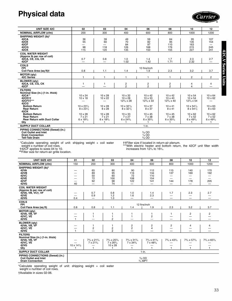
*Calculate operating weight of unit: shipping weight + coil waterweight x number of coil rows.
†42CF applies to sizes 04 to 10.**Filter size for return-air grille location.
††Filter size if located in return-air plenum.***With electric heater and bottom return, the 42CF unit filter width
increases from 123/4 to 163/4.
*Calculate operating weight of unit: shipping weight + coil waterweight x number of coil rows.
†Available in sizes 02-06.
UNIT SIZE 42C 02 03 04 06 08 10 12NOMINAL AIRFLOW (cfm) 200 300 400 600 800 1000 1200SHIPPING WEIGHT (lb)* 42CA 36 39 49 59 64 95 107 42CE 55 60 70 82 95 135 154 42CF — — 84 97 110 163 — 42CG 98 118 126 168 176 215 245 42CK 115 120 135 150 155 227 241COIL WATER WEIGHT(Approx lb per row of coil) 42CA, CE, CG, CK 0.7 0.8 1.0 1.4 1.7 2.3 2.7 42CF — — 1.02 1.42 1.71 2.32 —COILS FPI 10 fins/inch Coil Face Area (sq ft)† 0.8 1.1 1.4 1.9 2.3 3.2 3.7MOTOR (qty) 42C Series 1 1 1 1 1 2 2BLOWER (qty) 42CA, CE, CG, CK 1 1 2 2 2 4 4 42CF — — 2 2 2 4 —FILTERS Nominal Size (in.) (1-in. thick) 42CA** 10 x 24 10 x 28 10 x 32 10 x 42 10 x 42 10 x 54 10 x 64 42CE†† 10 x 18 10 x 22 10 x 28 10 x 33 10 x 40 10 x 54 10 x 62 42CF††*** — — 123/4 x 28 123/4 x 33 123/4 x 40 123/4 x 54 — 42CG Bottom Return 10 x 231/2 10 x 28 10 x 321/2 10 x 37 10 x 41 10 x 541/2 10 x 63 Rear Return 8 x 231/2 8 x 28 8 x 321/2 8 x 37 8 x 41 8 x 541/2 8 x 63 42CK Bottom Return 10 x 28 10 x 28 10 x 33 10 x 45 10 x 45 10 x 62 10 x 62 Rear Return 7 x 21 7 x 21 7 x 27 7 x 38 7 x 38 7 x 52 7 x 52 Rear Return with Duct Collar 6 x 183/4 6 x 183/4 6 x 243/4 6 x 353/4 6 x 353/4 6 x 493/4 6 x 493/4 Qty 1 1 1 1 1 1 1SUPPLY DUCT COLLAR 1-in.PIPING CONNECTIONS (Sweat) (in.) Coil Outlet and Inlet 5/8 OD Drain Connection 7/8 OD Tell-Tale Drain 5/8 OD
UNIT SIZE 42V 01 02 03 04 06 08 10 12NOMINAL AIRFLOW (cfm) 150 200 300 400 600 800 1000 1200SHIPPING WEIGHT (lb)* 42VA — 65 80 90 112 115 140 170 42VB — 89 95 116 134 137 169 192 42VC — 50 60 72 110 — — — 42VE — 72 100 108 154 — — — 42VF — 92 98 122 141 144 178 205 42VG 40 — 74 — — — — —COIL WATER WEIGHT (Approx lb per row of coil) 42VA, VB, VC†, VF — 0.7 0.8 1.0 1.4 1.7 2.3 2.7 42VE — 0.9 1.2 1.6 2.3 — — — 42VG 0.4 — 1.0 — — — — —COILS FPI 12 fins/inch Coil Face Area (sq ft) 0.8 0.8 1.1 1.4 1.9 2.3 3.2 3.7MOTOR (qty) 42VA, VB, VF — 1 1 1 1 1 2 2 42VC, VE — 1 1 1 2 — — — 42VG 1 — 2 — — — — —BLOWER (qty) 42VA, VB, VF — 1 1 2 2 2 4 4 42VC, VE — 2 2 2 4 — — — 42VG 1 — 2 — — — — —FILTERSNominal Size (in.) (1-in. thick) 42VA, VB, VF — 73/4 x 213/4 73/4 x 253/4 73/4 x 313/4 73/4 x 413/4 73/4 x 433/4 73/4 x 573/4 73/4 x 653/4 42VC, VE — 7 x 213/4 7 x 263/4 7 x 343/4 7 x 483/4 — — — 42VG 10 x 141/2 — 10 x 28 — — — — — Qty 1 1 1 1 1 1 1 1SUPPLY DUCT COLLAR 1-in.PIPING CONNECTIONS (Sweat) (in.) Coil Outlet and Inlet 5/8 OD Drain Connection 3/4 MPT
Physical data4
2C
,V S
eries Units
34
Base unit dimensions4
2C
,V S
erie
s U
nits
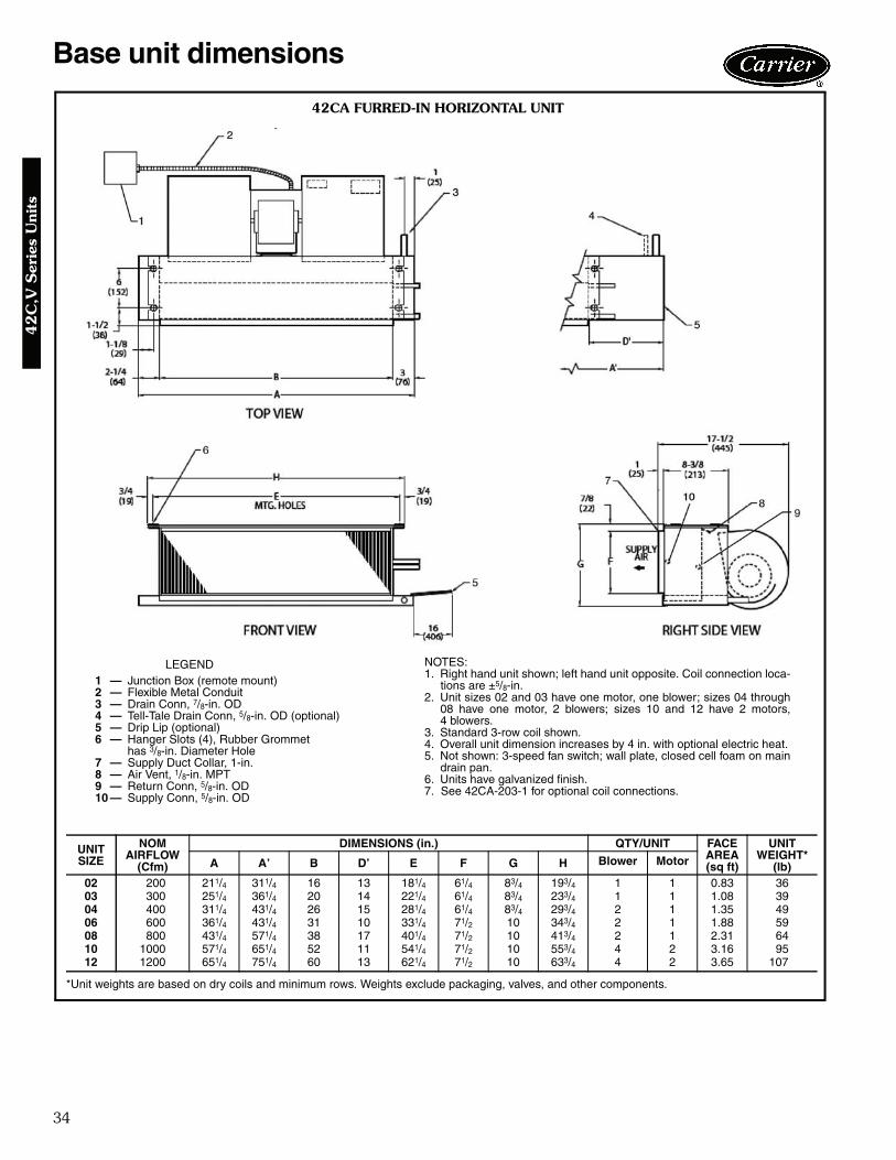
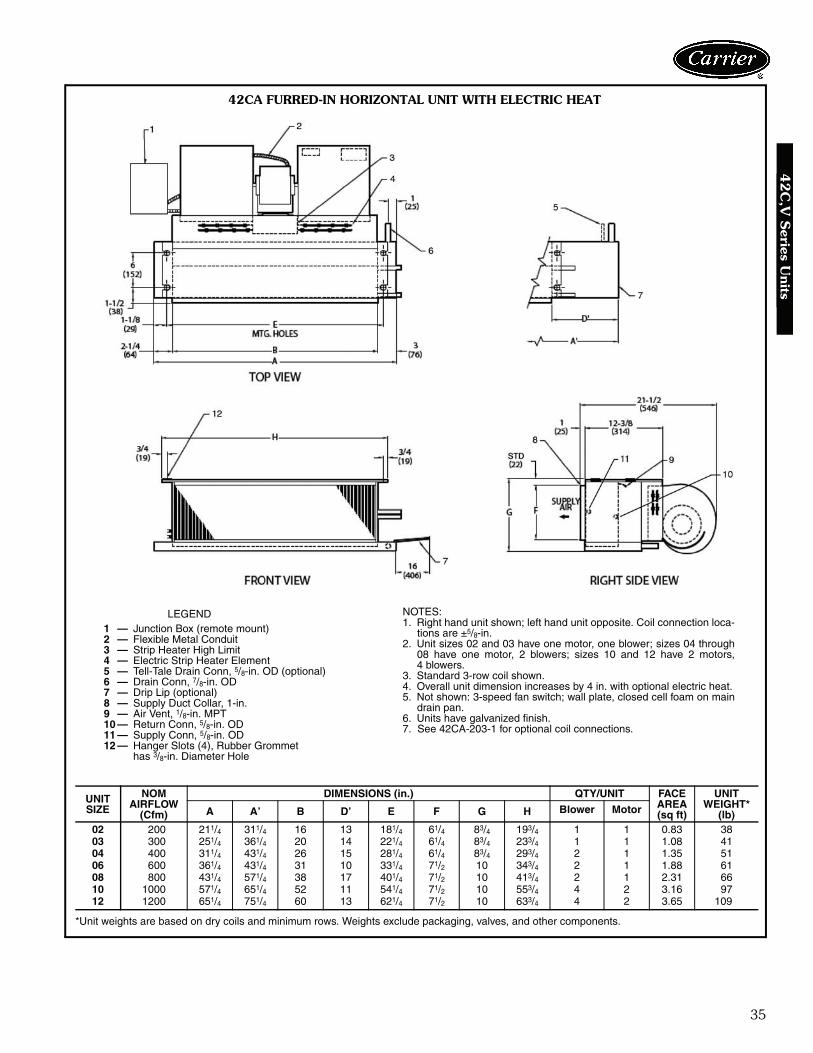
42CA FURRED-IN HORIZONTAL UNIT
LEGEND1 — Junction Box (remote mount)2 — Flexible Metal Conduit3 — Drain Conn, 7/8-in. OD4 — Tell-Tale Drain Conn, 5/8-in. OD (optional)5 — Drip Lip (optional)6 — Hanger Slots (4), Rubber Grommet
has 3/8-in. Diameter Hole7 — Supply Duct Collar, 1-in.8 — Air Vent, 1/8-in. MPT9 — Return Conn, 5/8-in. OD10 — Supply Conn, 5/8-in. OD
*Unit weights are based on dry coils and minimum rows. Weights exclude packaging, valves, and other components.
UNITSIZE
NOMAIRFLOW
(Cfm)
DIMENSIONS (in.) QTY/UNIT FACEAREA(sq ft)
UNIT WEIGHT*
(lb)A A’ B D’ E F G H Blower Motor
02 200 211/4 311/4 16 13 181/4 61/4 83/4 193/4 1 1 0.83 3603 300 251/4 361/4 20 14 221/4 61/4 83/4 233/4 1 1 1.08 3904 400 311/4 431/4 26 15 281/4 61/4 83/4 293/4 2 1 1.35 4906 600 361/4 431/4 31 10 331/4 71/2 10 343/4 2 1 1.88 5908 800 431/4 571/4 38 17 401/4 71/2 10 413/4 2 1 2.31 6410 1000 571/4 651/4 52 11 541/4 71/2 10 553/4 4 2 3.16 9512 1200 651/4 751/4 60 13 621/4 71/2 10 633/4 4 2 3.65 107
NOTES:1. Right hand unit shown; left hand unit opposite. Coil connection loca-
tions are ±5/8-in.2. Unit sizes 02 and 03 have one motor, one blower; sizes 04 through
08 have one motor, 2 blowers; sizes 10 and 12 have 2 motors,4 blowers.
3. Standard 3-row coil shown.4. Overall unit dimension increases by 4 in. with optional electric heat.5. Not shown: 3-speed fan switch; wall plate, closed cell foam on main
drain pan.6. Units have galvanized finish.7. See 42CA-203-1 for optional coil connections. a42-4099.eps
35
42
C,V
Series U
nits
42CA FURRED-IN HORIZONTAL UNIT WITH ELECTRIC HEAT
LEGEND1 — Junction Box (remote mount)2 — Flexible Metal Conduit3 — Strip Heater High Limit4 — Electric Strip Heater Element5 — Tell-Tale Drain Conn, 5/8-in. OD (optional)6 — Drain Conn, 7/8-in. OD7 — Drip Lip (optional)8 — Supply Duct Collar, 1-in.9 — Air Vent, 1/8-in. MPT10 — Return Conn, 5/8-in. OD11 — Supply Conn, 5/8-in. OD12 — Hanger Slots (4), Rubber Grommet
has 3/8-in. Diameter Hole
NOTES:1. Right hand unit shown; left hand unit opposite. Coil connection loca-
tions are ±5/8-in.2. Unit sizes 02 and 03 have one motor, one blower; sizes 04 through
08 have one motor, 2 blowers; sizes 10 and 12 have 2 motors,4 blowers.
3. Standard 3-row coil shown.4. Overall unit dimension increases by 4 in. with optional electric heat.5. Not shown: 3-speed fan switch; wall plate, closed cell foam on main
drain pan.6. Units have galvanized finish.7. See 42CA-203-1 for optional coil connections.
*Unit weights are based on dry coils and minimum rows. Weights exclude packaging, valves, and other components.
UNITSIZE
NOMAIRFLOW
(Cfm)
DIMENSIONS (in.) QTY/UNIT FACEAREA(sq ft)
UNIT WEIGHT*
(lb)A A’ B D’ E F G H Blower Motor
02 200 211/4 311/4 16 13 181/4 61/4 83/4 193/4 1 1 0.83 3803 300 251/4 361/4 20 14 221/4 61/4 83/4 233/4 1 1 1.08 4104 400 311/4 431/4 26 15 281/4 61/4 83/4 293/4 2 1 1.35 5106 600 361/4 431/4 31 10 331/4 71/2 10 343/4 2 1 1.88 6108 800 431/4 571/4 38 17 401/4 71/2 10 413/4 2 1 2.31 6610 1000 571/4 651/4 52 11 541/4 71/2 10 553/4 4 2 3.16 9712 1200 651/4 751/4 60 13 621/4 71/2 10 633/4 4 2 3.65 109
a42-4100.eps
36
Base unit dimensions (cont)4
2C
,V S
erie
s U
nits
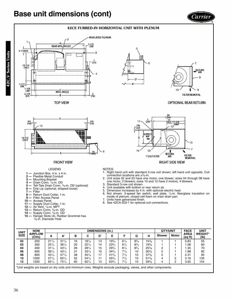
42CE FURRED-IN HORIZONTAL UNIT WITH PLENUM
NOTES:1. Right hand unit with standard 3-row coil shown; left hand unit opposite. Coil
connection locations are ±5/8-in.2. Unit sizes 02 and 03 have one motor, one blower; sizes 04 through 08 have
one motor, 2 blowers; sizes 10 and 12 have 2 motors, 4 blowers.3. Standard 3-row coil shown.4. Unit available with bottom or rear return air.5. Dimension increases by 4 in. with optional electric heat.6. Not shown: 3-speed fan switch; wall plate, 1/2-in. fiberglass insulation on
inside of plenum, closed cell foam on main drain pan.7. Units have galvanized finish.8. See 42CA-203-1 for optional coil connections.
LEGEND1 — Junction Box, 4 in. x 4 in.2 — Flexible Metal Conduit3 — Mounting Bracket4 — Drain Conn, 7/8-in. OD5 — Tell-Tale Drain Conn, 5/8-in. OD (optional)6 — Drip Lip (optional, shipped loose)7 — Filter8 — Return Duct Collar, 1-in.9 — Filter Access Panel
10 — Access Panel11 — Supply Duct Collar, 1-in.12 — Air Vent, 1/8-in. MPT13 — Return Conn, 5/8-in. OD14 — Supply Conn, 5/8-in. OD15 — Hanger Slots (4), Rubber Grommet has
3/8-in. Diameter Hole
*Unit weights are based on dry coils and minimum rows. Weights exclude packaging, valves, and other components.
UNITSIZE
NOMAIRFLOW
(Cfm)
DIMENSIONS (in.) QTY/UNIT FACEAREA(sq ft)
UNIT WEIGHT*
(lb)A A’ B C D’ E F G H Blower Motor
02 200 211/4 311/4 16 181/4 13 193/4 61/4 83/4 153/8 1 1 0.83 5503 300 251/4 361/4 20 221/4 14 233/4 61/4 83/4 193/8 1 1 1.08 6004 400 311/4 431/4 26 281/4 15 293/4 61/4 83/4 253/8 2 1 1.35 7006 600 361/4 431/4 31 331/4 10 343/4 71/2 10 303/8 2 1 1.88 8208 800 431/4 571/4 38 401/4 17 413/4 71/2 10 373/8 2 1 2.31 9510 1000 571/4 651/4 52 541/4 11 553/4 71/2 10 513/8 4 2 3.16 13512 1200 651/4 751/4 60 621/4 13 633/4 71/2 10 593/8 4 2 3.65 154
a42-4101
37
42
C,V
Series U
nits
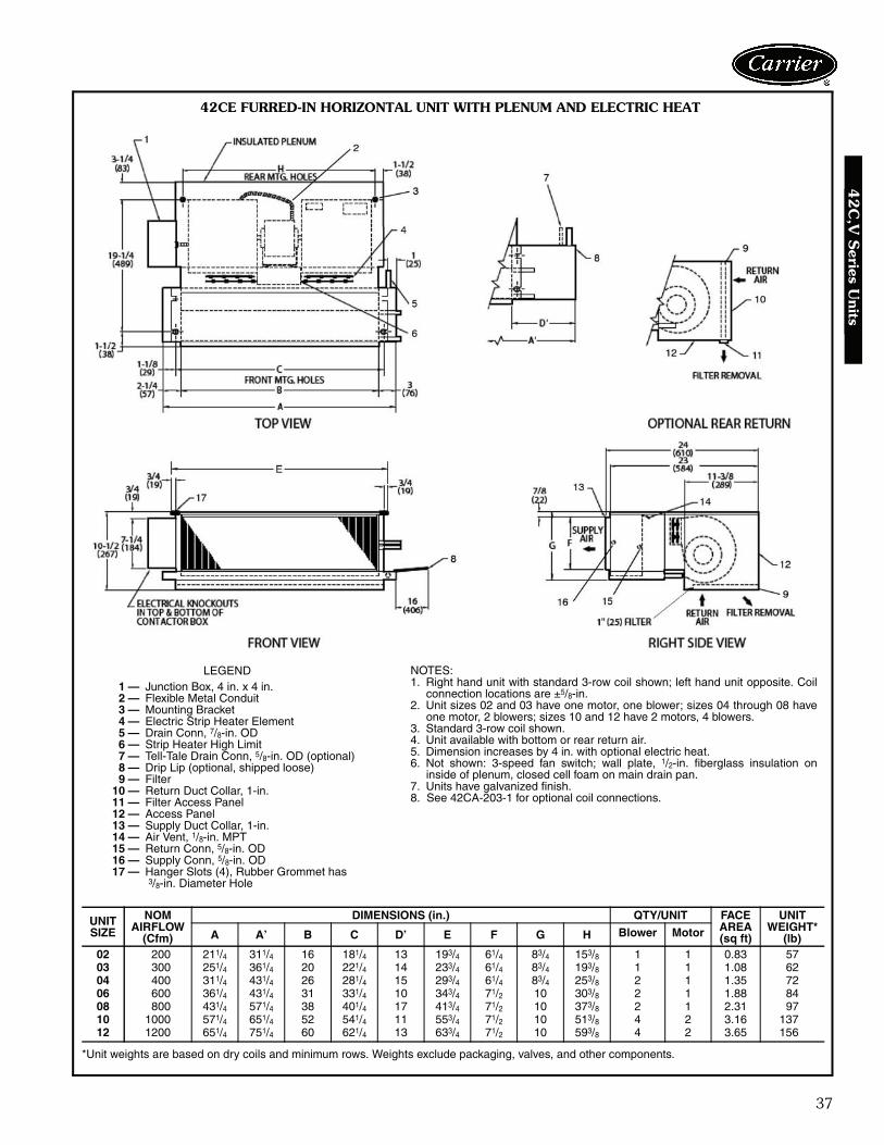
42CE FURRED-IN HORIZONTAL UNIT WITH PLENUM AND ELECTRIC HEAT
NOTES:1. Right hand unit with standard 3-row coil shown; left hand unit opposite. Coil
connection locations are ±5/8-in.2. Unit sizes 02 and 03 have one motor, one blower; sizes 04 through 08 have
one motor, 2 blowers; sizes 10 and 12 have 2 motors, 4 blowers.3. Standard 3-row coil shown.4. Unit available with bottom or rear return air.5. Dimension increases by 4 in. with optional electric heat.6. Not shown: 3-speed fan switch; wall plate, 1/2-in. fiberglass insulation on
inside of plenum, closed cell foam on main drain pan.7. Units have galvanized finish.8. See 42CA-203-1 for optional coil connections.
LEGEND1 — Junction Box, 4 in. x 4 in.2 — Flexible Metal Conduit3 — Mounting Bracket4 — Electric Strip Heater Element5 — Drain Conn, 7/8-in. OD6 — Strip Heater High Limit7 — Tell-Tale Drain Conn, 5/8-in. OD (optional)8 — Drip Lip (optional, shipped loose)9 — Filter
10 — Return Duct Collar, 1-in.11 — Filter Access Panel12 — Access Panel13 — Supply Duct Collar, 1-in.14 — Air Vent, 1/8-in. MPT15 — Return Conn, 5/8-in. OD16 — Supply Conn, 5/8-in. OD17 — Hanger Slots (4), Rubber Grommet has
3/8-in. Diameter Hole
*Unit weights are based on dry coils and minimum rows. Weights exclude packaging, valves, and other components.
UNITSIZE
NOMAIRFLOW
(Cfm)
DIMENSIONS (in.) QTY/UNIT FACEAREA(sq ft)
UNIT WEIGHT*
(lb)A A’ B C D’ E F G H Blower Motor
02 200 211/4 311/4 16 181/4 13 193/4 61/4 83/4 153/8 1 1 0.83 5703 300 251/4 361/4 20 221/4 14 233/4 61/4 83/4 193/8 1 1 1.08 6204 400 311/4 431/4 26 281/4 15 293/4 61/4 83/4 253/8 2 1 1.35 7206 600 361/4 431/4 31 331/4 10 343/4 71/2 10 303/8 2 1 1.88 8408 800 431/4 571/4 38 401/4 17 413/4 71/2 10 373/8 2 1 2.31 9710 1000 571/4 651/4 52 541/4 11 553/4 71/2 10 513/8 4 2 3.16 13712 1200 651/4 751/4 60 621/4 13 633/4 71/2 10 593/8 4 2 3.65 156
A42-4102
38
Base unit dimensions (cont)4
2C
,V S
erie
s U
nits
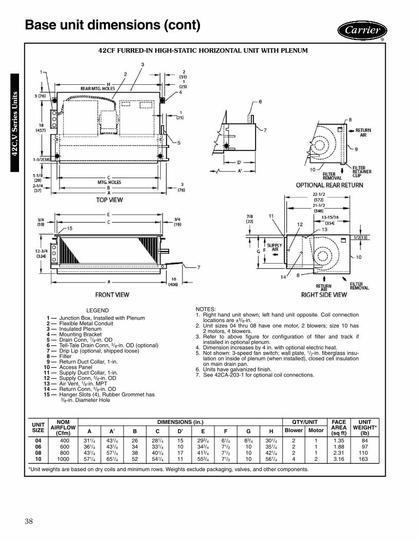
42CF FURRED-IN HIGH-STATIC HORIZONTAL UNIT WITH PLENUM
LEGEND1 — Junction Box, Installed with Plenum2 — Flexible Metal Conduit3 — Insulated Plenum4 — Mounting Bracket5 — Drain Conn, 7/8-in. OD6 — Tell-Tale Drain Conn, 5/8-in. OD (optional)7 — Drip Lip (optional, shipped loose)8 — Filter9 — Return Duct Collar, 1-in.
10 — Access Panel11 — Supply Duct Collar, 1-in.12 — Supply Conn, 5/8-in. OD13 — Air Vent, 1/8-in. MPT14 — Return Conn, 5/8-in. OD15 — Hanger Slots (4), Rubber Grommet has
3/8-in. Diameter Hole
*Unit weights are based on dry coils and minimum rows. Weights exclude packaging, valves, and other components.
UNITSIZE
NOMAIRFLOW
(Cfm)
DIMENSIONS (in.) QTY/UNIT FACEAREA(sq ft)
UNIT WEIGHT*
(lb)A A’ B C D’ E F G H Blower Motor
04 400 311/4 431/4 26 281/4 15 293/4 61/4 83/4 301/4 2 1 1.35 8406 600 361/4 431/4 34 331/4 10 343/4 71/2 10 351/4 2 1 1.88 9708 800 431/4 571/4 38 401/4 17 413/4 71/2 10 421/4 2 1 2.31 11010 1000 571/4 651/4 52 541/4 11 553/4 71/2 10 561/4 4 2 3.16 163
NOTES:1. Right hand unit shown; left hand unit opposite. Coil connection
locations are ±5/8-in.2. Unit sizes 04 thru 08 have one motor, 2 blowers; size 10 has
2 motors, 4 blowers.3. Refer to above figure for configuration of filter and track if
installed in optional plenum.4. Dimension increases by 4 in. with optional electric heat.5. Not shown: 3-speed fan switch; wall plate, 1/2-in. fiberglass insu-
lation on inside of plenum (when installed), closed cell insulationon main drain pan.
6. Units have galvanized finish.7. See 42CA-203-1 for optional coil connections.
A42-4103

39
42
C,V
Series U
nits
42CF FURRED-IN HORIZONTAL UNIT WITH PLENUM AND ELECTRIC HEAT
LEGEND1 — Junction Box, Installed with Plenum2 — Plenum3 — Flexible Metal Conduit4 — Mounting Bracket5 — Electric Strip Heater Element6 — Drain Conn, 7/8-in. OD7 — Drip Lip (optional, shipped loose)8 — Tell-Tale Drain Conn, 5/8-in. OD (optional)9 — Filter
10 — Return Duct Collar, 1-in.11 — Air Vent, 1/8-in. MPT12 — Access Panel13 — Return Conn, 5/8-in. OD14 — Supply Conn, 5/8-in. OD15 — Supply Duct Collar, 1-in.16 — Hanger Slots (4), Rubber Grommet has
3/8-in. Diameter Hole
NOTES:1. Right hand unit shown; left hand unit opposite. Coil connection
locations are ±5/8-in.2. Unit sizes 04 thru 08 have one motor, 2 blowers; size 10 has
2 motors, 4 blowers.3. Refer to above figure for configuration of filter and track if
installed in optional plenum.4. Dimension increases by 4 in. with optional electric heat.5. Not shown: 3-speed fan switch; wall plate, 1/2-in. fiberglass insu-
lation on inside of plenum (when installed), closed cell insulationon main drain pan.
6. Units have galvanized finish.7. See 42CA-203-1 for optional coil connections.
*Unit weights are based on dry coils and minimum rows. Weights exclude packaging, valves, and other components.
UNITSIZE
NOMAIRFLOW
(Cfm)
DIMENSIONS (in.) QTY/UNIT FACEAREA(sq ft)
UNIT WEIGHT*
(lb)A A’ B C D’ E F G H Blower Motor
04 400 311/4 431/4 26 281/4 15 293/4 61/4 83/4 301/4 2 1 1.35 8406 600 361/4 431/4 34 331/4 10 343/4 71/2 10 351/4 2 1 1.88 9708 800 431/4 571/4 38 401/4 17 413/4 71/2 10 421/4 2 1 2.31 11010 1000 571/4 651/4 52 541/4 11 553/4 71/2 10 561/4 4 2 3.16 163
A42-4104
40
Base unit dimensions (cont)4
2C
,V S
erie
s U
nits
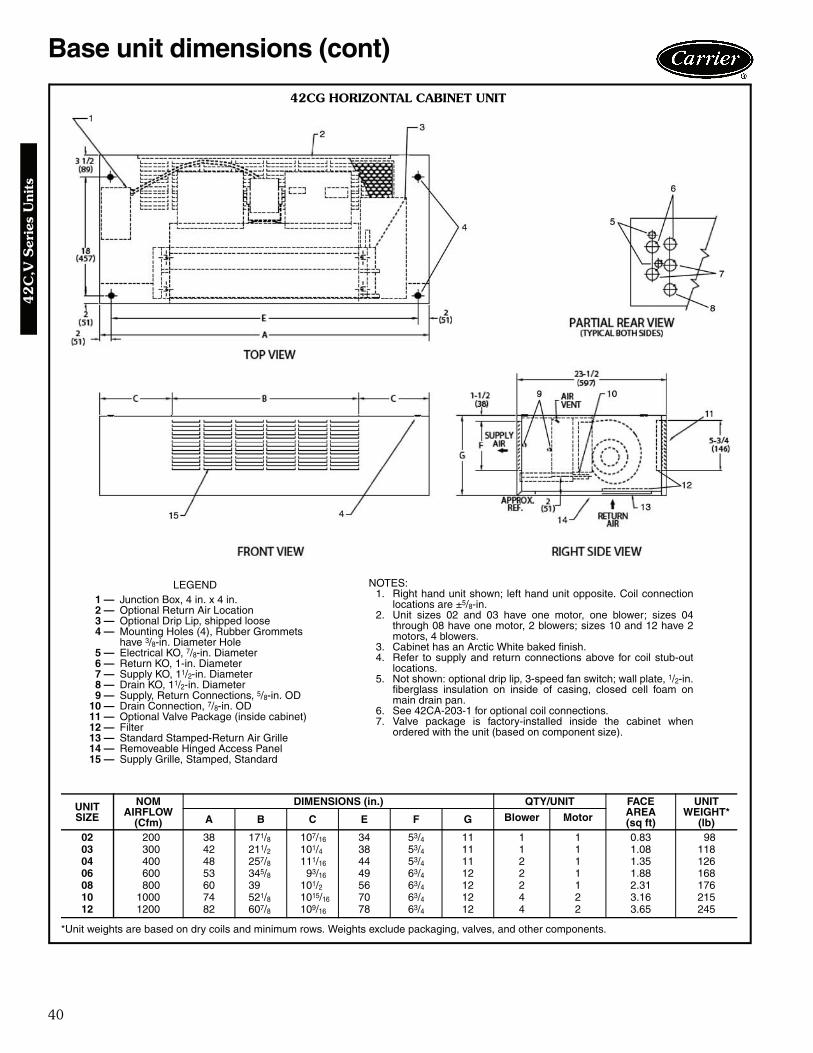
42CG HORIZONTAL CABINET UNIT
LEGEND1 — Junction Box, 4 in. x 4 in.2 — Optional Return Air Location3 — Optional Drip Lip, shipped loose4 — Mounting Holes (4), Rubber Grommets
have 3/8-in. Diameter Hole5 — Electrical KO, 7/8-in. Diameter6 — Return KO, 1-in. Diameter7 — Supply KO, 11/2-in. Diameter8 — Drain KO, 11/2-in. Diameter9 — Supply, Return Connections, 5/8-in. OD
10 — Drain Connection, 7/8-in. OD11 — Optional Valve Package (inside cabinet)12 — Filter13 — Standard Stamped-Return Air Grille14 — Removeable Hinged Access Panel15 — Supply Grille, Stamped, Standard
*Unit weights are based on dry coils and minimum rows. Weights exclude packaging, valves, and other components.
UNITSIZE
NOMAIRFLOW
(Cfm)
DIMENSIONS (in.) QTY/UNIT FACEAREA(sq ft)
UNIT WEIGHT*
(lb)A B C E F G Blower Motor
02 200 38 171/8 107/16 34 53/4 11 1 1 0.83 9803 300 42 211/2 101/4 38 53/4 11 1 1 1.08 11804 400 48 257/8 111/16 44 53/4 11 2 1 1.35 12606 600 53 345/8 93/16 49 63/4 12 2 1 1.88 16808 800 60 39 101/2 56 63/4 12 2 1 2.31 17610 1000 74 521/8 1015/16 70 63/4 12 4 2 3.16 21512 1200 82 607/8 109/16 78 63/4 12 4 2 3.65 245
NOTES:1. Right hand unit shown; left hand unit opposite. Coil connection
locations are ±5/8-in.2. Unit sizes 02 and 03 have one motor, one blower; sizes 04
through 08 have one motor, 2 blowers; sizes 10 and 12 have 2motors, 4 blowers.
3. Cabinet has an Arctic White baked finish.4. Refer to supply and return connections above for coil stub-out
locations.5. Not shown: optional drip lip, 3-speed fan switch; wall plate, 1/2-in.
fiberglass insulation on inside of casing, closed cell foam onmain drain pan.
6. See 42CA-203-1 for optional coil connections.7. Valve package is factory-installed inside the cabinet when
ordered with the unit (based on component size).
A42-4105
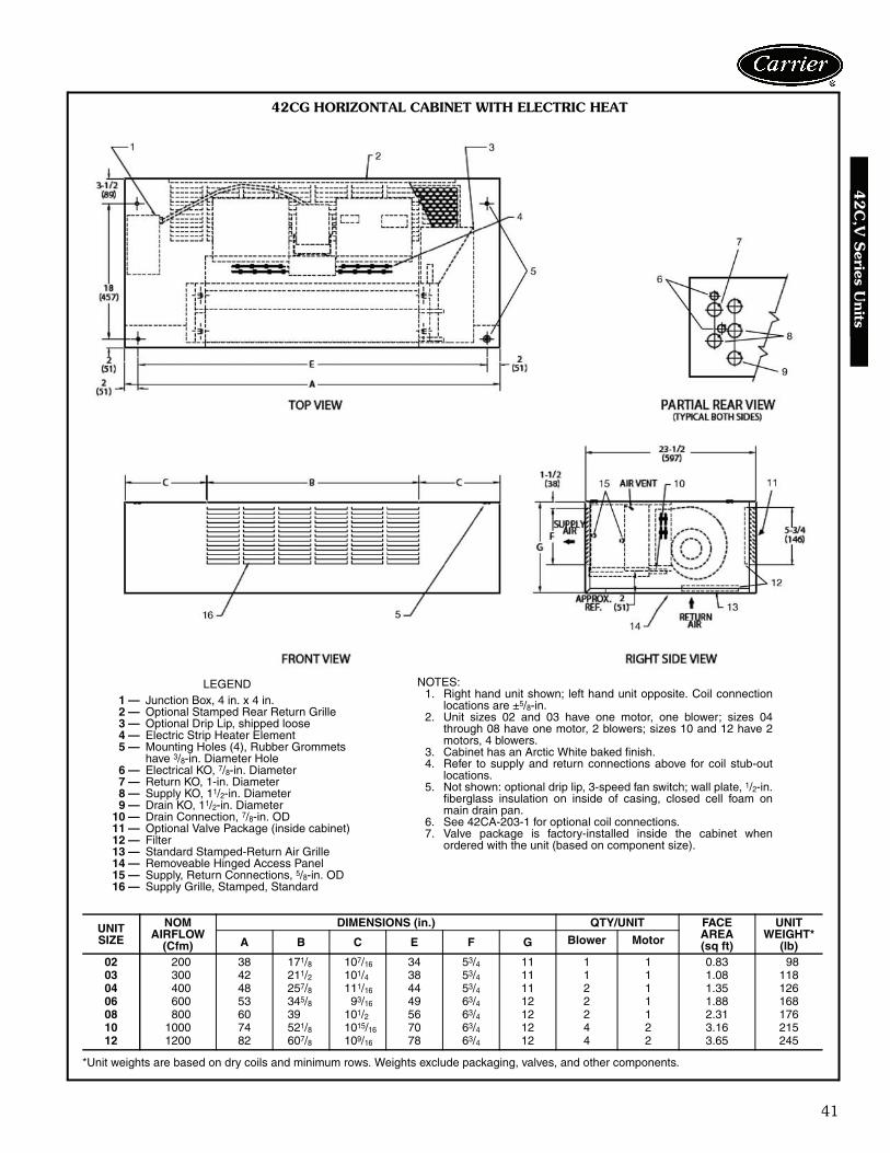
41
42
C,V
Series U
nits
42CG HORIZONTAL CABINET WITH ELECTRIC HEAT
LEGEND1 — Junction Box, 4 in. x 4 in.2 — Optional Stamped Rear Return Grille3 — Optional Drip Lip, shipped loose4 — Electric Strip Heater Element5 — Mounting Holes (4), Rubber Grommets
have 3/8-in. Diameter Hole6 — Electrical KO, 7/8-in. Diameter7 — Return KO, 1-in. Diameter8 — Supply KO, 11/2-in. Diameter9 — Drain KO, 11/2-in. Diameter
10 — Drain Connection, 7/8-in. OD11 — Optional Valve Package (inside cabinet)12 — Filter13 — Standard Stamped-Return Air Grille14 — Removeable Hinged Access Panel15 — Supply, Return Connections, 5/8-in. OD16 — Supply Grille, Stamped, Standard
NOTES:1. Right hand unit shown; left hand unit opposite. Coil connection
locations are ±5/8-in.2. Unit sizes 02 and 03 have one motor, one blower; sizes 04
through 08 have one motor, 2 blowers; sizes 10 and 12 have 2motors, 4 blowers.
3. Cabinet has an Arctic White baked finish.4. Refer to supply and return connections above for coil stub-out
locations.5. Not shown: optional drip lip, 3-speed fan switch; wall plate, 1/2-in.
fiberglass insulation on inside of casing, closed cell foam onmain drain pan.
6. See 42CA-203-1 for optional coil connections.7. Valve package is factory-installed inside the cabinet when
ordered with the unit (based on component size).
*Unit weights are based on dry coils and minimum rows. Weights exclude packaging, valves, and other components.
UNITSIZE
NOMAIRFLOW
(Cfm)
DIMENSIONS (in.) QTY/UNIT FACEAREA(sq ft)
UNIT WEIGHT*
(lb)A B C E F G Blower Motor
02 200 38 171/8 107/16 34 53/4 11 1 1 0.83 9803 300 42 211/2 101/4 38 53/4 11 1 1 1.08 11804 400 48 257/8 111/16 44 53/4 11 2 1 1.35 12606 600 53 345/8 93/16 49 63/4 12 2 1 1.88 16808 800 60 39 101/2 56 63/4 12 2 1 2.31 17610 1000 74 521/8 1015/16 70 63/4 12 4 2 3.16 21512 1200 82 607/8 109/16 78 63/4 12 4 2 3.65 245
A42-4106

42
Base unit dimensions (cont)4
2C
,V S
erie
s U
nits
42CK HORIZONTAL CABINET UNIT WITH TELESCOPIC ACCESS PANEL
LEGEND1 — Junction Box, 4 in. x 4 in.2 — Optional Drip Lip, shipped loose3 — Mounting Holes (4), Rubber Grommets
have 3/8-in. Diameter Hole4 — Piping KO, 11/2-in. Diameter5 — Electrical KO, 7/8-in. Diameter6 — Drain KO, 11/2-in. Diameter7 — Supply Duct Collar8 — Return Connection, 5/8-in. OD.9 — Optional Rear Return. Consult factory for
collar dimensions.10 — Drain, 7/8-in. OD.11 — Stamped Bottom Return Air Grille12 — Filter13 — Stamped Air Supply Grille14 — Hinged Bottom Access Panel15 — Supply Connection, 5/8-in. OD.
*Unit weights are based on dry coils and minimum rows. Weights exclude packaging, valves, and other components.
UNITSIZE
NOMAIRFLOW
(Cfm)
DIMENSIONS (in.) QTY/UNIT FACE AREA(sq ft)
UNIT WEIGHT* (lb)A D E F Blower Motor
02 200 35 37 32 6 1 1 0.83 11503 300 35 37 32 6 1 1 1.08 12004 400 41 43 38 6 2 1 1.35 13506 600 53 55 50 7 2 1 1.88 15008 800 53 55 50 7 2 1 2.31 15510 1000 75 77 72 7 4 2 3.16 22712 1200 75 77 72 7 4 2 3.65 241
NOTES:1. Right hand unit shown; left hand unit opposite. Coil connection
locations are ±5/8-in.2. Unit sizes 02 and 03 have one motor, one blower; sizes 04
through 08 have one motor, 2 blowers; sizes 10 and 12 have 2motors, 4 blowers.
3. Bottom access panel has an Arctic White baked finish.4. Refer to supply and return connections above for coil stub-out
locations.5. Not shown: optional drip lip, 3-speed fan switch; wall plate, 1/2-in.
fiberglass insulation on inside of casing, closed cell foam onmain drain pan.
6. See 42CA-203-1 for optional coil connections.7. Valve package is factory-installed inside the cabinet when
ordered with the unit (based on component size).
A42-4107
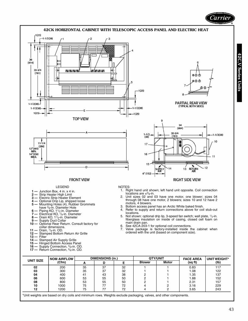
43
42
C,V
Series U
nits
42CK HORIZONTAL CABINET WITH TELESCOPIC ACCESS PANEL AND ELECTRIC HEAT
LEGEND1 — Junction Box, 4 in. x 4 in.2 — Strip Heater High Limit3 — Electric Strip Heater Element4 — Optional Drip Lip, shipped loose5 — Mounting Holes (4), Rubber Grommets
have 3/8-in. Diameter Hole6 — Piping KO, 11/2-in. Diameter7 — Electrical KO, 7/8-in. Diameter8 — Drain KO, 11/2-in. Diameter9 — Supply Duct Collar
10 — Optional Rear Return. Consult factory for collar dimensions.
11 — Drain, 7/8-in. OD.12 — Stamped Bottom Return Air Grille13 — Filter14 — Stamped Air Supply Grille15 — Hinged Bottom Access Panel16 — Supply Connection, 5/8-in. OD.17 — Return Connection, 5/8-in. OD.
NOTES:1. Right hand unit shown; left hand unit opposite. Coil connection
locations are ±5/8-in.2. Unit sizes 02 and 03 have one motor, one blower; sizes 04
through 08 have one motor, 2 blowers; sizes 10 and 12 have 2motors, 4 blowers.
3. Bottom access panel has an Arctic White baked finish.4. Refer to supply and return connections above for coil stub-out
locations.5. Not shown: optional drip lip, 3-speed fan switch; wall plate, 1/2-in.
fiberglass insulation on inside of casing, closed cell foam onmain drain pan.
6. See 42CA-203-1 for optional coil connections.7. Valve package is factory-installed inside the cabinet when
ordered with the unit (based on component size).
*Unit weights are based on dry coils and minimum rows. Weights exclude packaging, valves, and other components.
UNIT SIZE NOM AIRFLOW(Cfm)
DIMENSIONS (in.) QTY/UNIT FACE AREA(sq ft)
UNIT WEIGHT* (lb)A D E Blower Motor
02 200 35 37 32 1 1 0.83 11703 300 35 37 32 1 1 1.08 12204 400 41 43 38 2 1 1.35 13706 600 53 55 50 2 1 1.88 15208 800 53 55 50 2 1 2.31 15710 1000 75 77 72 4 2 3.16 22912 1200 75 77 72 4 2 3.65 243
A42-4108

44
Base unit dimensions (cont)4
2C
,V S
erie
s U
nits
42VA FURRED-IN VERTICAL UNIT
LEGEND1 — Optional Unit Mounted Control Box2 — Wall Mounting Holes (4), 3/4-in. Diameter3 — Drain, 3/4-in. MPT4 — Drain Pan, Auxiliary, Shipped Loose5 — Supply Conn, 5/8-in. OD6 — Return Conn, 5/8-in. OD7 — Filter8 — Air Vent, 1/8-in. MPT9 — Discharge Opening
10 — Flexible Conduit11 — Front Access Panel
*Unit weights are based on dry coils and minimum rows. Weights exclude packaging, valves, and other components.
UNITSIZE
NOMAIRFLOW
(Cfm)
DIMENSIONS (in.) QTY/UNIT FACEAREA(sq ft)
UNIT WEIGHT*
(lb)A B C D Blower Motor
02 200 25 22 231/2 16 1 1 0.83 6503 300 29 26 271/2 20 1 1 1.08 8004 400 35 32 331/2 26 2 1 1.35 9006 600 45 42 431/2 36 2 1 1.88 11208 800 47 44 451/2 38 2 1 2.31 11510 1000 61 58 591/2 52 4 2 3.16 14012 1200 69 66 671/2 60 4 2 3.65 170
NOTES:1. Right hand unit shown; left hand unit opposite. Coil connection
locations are ± 5/8-in.2. Unit sizes 02 and 03 have one motor, one blower; sizes 04 through
08 have one motor, 2 blowers; sizes 10 and 12 have 2 motors, 4blowers.
3. Standard 3-row coil shown.4. Optional unit-mounted switch box and controls, when specified,
are installed on opposite side from cooling connections.5. Not shown: 3-speed fan switch; wall plate, 1/2-in. fiberglass insula-
tion on inside of casing, closed cell foam on main drain pan.6. Units have galvanized finish.7. See 42VA-203-1 for optional coil connections.
A42-4109

45
42VB VERTICAL CABINET UNIT
LEGEND1 — Standard Stamped Supply Grille2 — Access Door, Fan Switch3 — Supply Conn, 5/8-in. OD4 — Return Conn, 5/8-in. OD5 — Drain, 3/4-in. MPT6 — Filter7 — Air Vent, 1/8-in. MPT8 — Front Panel Fastener9 — Drain Pan, Auxiliary, Shipped Loose
10 — Wall Mounting Holes (4), 3/4-in. Diameter11 — Flexible Conduit12 — Fan Switch, 3-speed13 — Front Access Panel
NOTES:1. Right hand unit shown; left hand unit opposite. Coil connection
locations are ± 5/8-in.2. Unit sizes 02 and 03 have one motor, one blower; sizes 04 through
08 have one motor, 2 blowers; sizes 10 and 12 have 2 motors, 4blowers.
3. Standard 3-row coil shown.4. Cabinet has an Arctic White baked finish.5. Stamped supply grille standard. Optional single or double deflec-
tion grilles available.6. Not shown: 1/2-in. fiberglass insulation on inside of casing, closed
cell foam on main drain pan.7. See 42VA-203-1 for optional coil connections.
*Unit weights are based on dry coils and minimum rows. Weights exclude packaging, valves, and other components.
UNITSIZE
NOMAIRFLOW
(Cfm)
DIMENSIONS (in.) QTY/UNIT FACEAREA(sq ft)
UNIT WEIGHT*
(lb)A B C D E Blower Motor
02 200 41 22 231/2 171/4 35/8 1 1 0.83 8903 300 45 26 271/2 211/2 31/2 1 1 1.08 9504 400 51 32 331/2 26 41/4 2 1 1.35 11606 600 61 42 431/2 39 23/4 2 1 1.88 13408 800 63 44 451/2 39 33/4 2 1 2.31 13710 1000 77 58 591/2 52 41/4 4 2 3.16 16912 1200 85 66 671/2 61 33/4 4 2 3.65 192
A42-4110
42
C,V
Series U
nits
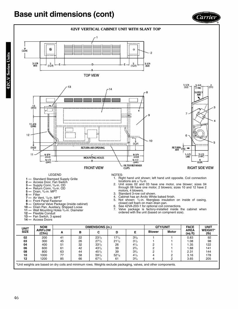
46
Base unit dimensions (cont)
42VF VERTICAL CABINET UNIT WITH SLANT TOP
LEGEND1 — Standard Stamped Supply Grille2 — Access Door, Fan Switch3 — Supply Conn, 5/8-in. OD4 — Return Conn, 5/8-in. OD5 — Drain, 3/4-in. MPT6 — Filter7 — Air Vent, 1/8-in. MPT8 — Front Panel Fastener9 — Optional Valve Package (inside cabinet)
10 — Drain Pan, Auxiliary, Shipped Loose11 — Wall Mounting Holes 3/4-in. Diameter12 — Flexible Conduit13 — Fan Switch, 3 speed14 — Access Doors
NOTES:1. Right hand unit shown; left hand unit opposite. Coil connection
locations are ± 5/8-in.2. Unit sizes 02 and 03 have one motor, one blower; sizes 04
through 08 have one motor, 2 blowers; sizes 10 and 12 have 2motors, 4 blowers.
3. Standard 3-row coil shown.4. Cabinet has an Arctic White baked finish.5. Not shown: 1/2-in. fiberglass insulation on inside of casing,
closed cell foam on main drain pan.6. See 42VA-203-1 for optional coil connections.7. Valve package is factory-installed inside the cabinet when
ordered with the unit (based on compnent size).
*Unit weights are based on dry coils and minimum rows. Weights exclude packaging, valves, and other components.
UNITSIZE
NOMAIRFLOW
(Cfm)
DIMENSIONS (in.) QTY/UNIT FACEAREA(sq ft)
UNIT WEIGHT*
(lb)A B C D E Blower Motor
02 200 41 22 231/2 171/4 35/8 1 1 0.83 9203 300 45 26 271/2 211/2 31/2 1 1 1.08 9804 400 51 32 331/2 26 41/4 2 1 1.35 12206 600 61 42 431/2 39 23/4 2 1 1.88 14108 800 63 44 451/2 39 33/4 2 1 2.31 14410 1000 77 58 591/2 521/8 41/4 4 2 3.16 17812 1200 85 66 671/2 61 33/4 4 2 3.65 205
A42-4111
42
C,V
Ser
ies
Uni
ts
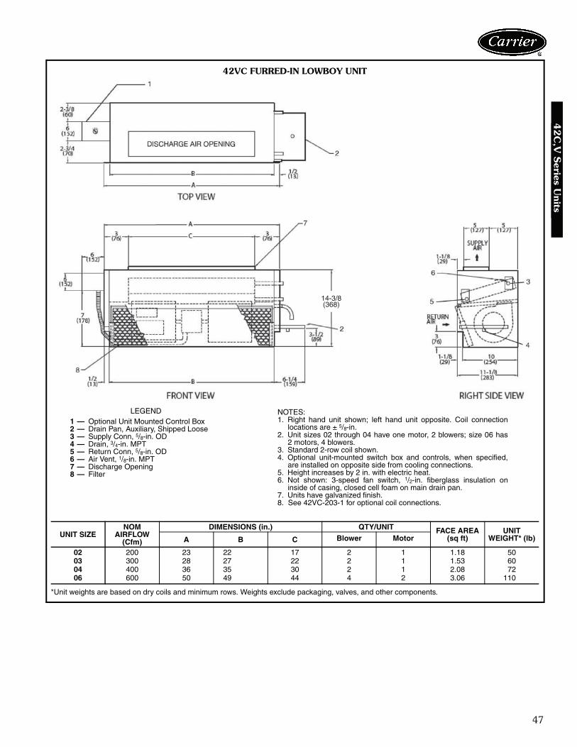
47
LEGEND1 — Optional Unit Mounted Control Box2 — Drain Pan, Auxiliary, Shipped Loose3 — Supply Conn, 5/8-in. OD4 — Drain, 3/4-in. MPT5 — Return Conn, 5/8-in. OD6 — Air Vent, 1/8-in. MPT7 — Discharge Opening8 — Filter
*Unit weights are based on dry coils and minimum rows. Weights exclude packaging, valves, and other components.
UNIT SIZENOM
AIRFLOW(Cfm)
DIMENSIONS (in.) QTY/UNIT FACE AREA(sq ft)
UNIT WEIGHT* (lb)A B C Blower Motor
02 200 23 22 17 2 1 1.18 5003 300 28 27 22 2 1 1.53 6004 400 36 35 30 2 1 2.08 7206 600 50 49 44 4 2 3.06 110
NOTES:1. Right hand unit shown; left hand unit opposite. Coil connection
locations are ± 5/8-in.2. Unit sizes 02 through 04 have one motor, 2 blowers; size 06 has
2 motors, 4 blowers.3. Standard 2-row coil shown.4. Optional unit-mounted switch box and controls, when specified,
are installed on opposite side from cooling connections.5. Height increases by 2 in. with electric heat.6. Not shown: 3-speed fan switch, 1/2-in. fiberglass insulation on
inside of casing, closed cell foam on main drain pan.7. Units have galvanized finish.8. See 42VC-203-1 for optional coil connections. A42-4112
14-3/8(368)
42VC FURRED-IN LOWBOY UNIT
42
C,V
Series U
nits

48
Base unit dimensions (cont)
42VC FURRED-IN LOWBOY UNIT WITH ELECTRIC HEAT
LEGEND1 — Unit-Mounted Control Box (Optional)2 — Drain Pan, Auxiliary, Shipped Loose3 — Air Vent, 1/8-in. MPT4 — Supply Conn, 5/8-in. OD5 — Drain, 3/4-in. MPT6 — Return Conn, 5/8-in. OD7 — Filter8 — Electical Sheath Heater Element9 — Discharge Opening
*Unit weights are based on dry coils and minimum rows. Weights exclude packaging, valves, and other components.
UNIT SIZENOM
AIRFLOW(Cfm)
DIMENSIONS (in.) QTY/UNIT FACE AREA(sq ft)
UNIT WEIGHT* (lb)A B C Blower Motor
02 200 23 22 17 2 1 1.18 5003 300 28 27 22 2 1 1.53 6004 400 36 35 30 2 1 2.08 7206 600 50 49 44 4 2 3.06 110
NOTES:1. Right hand unit shown; left hand unit opposite. Coil connection
locations are ± 5/8-in.2. Unit sizes 02 through 04 have one motor, 2 blowers; size 06 has
2 motors, 4 blowers.3. Standard 2-row coil shown.4. Optional unit-mounted switch box and controls, when specified,
are installed on opposite side from cooling connections.5. Height increases by 2 in. with electric heat.6. Not shown: 3-speed fan switch, 1/2-in. fiberglass insulation on
inside of casing, closed cell foam on main drain pan.7. Units have galvanized finish.8. See 42VC-203-1 for optional coil connections.
A42-4113
42
C,V
Ser
ies
Uni
ts
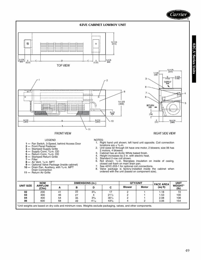
49
*Unit weights are based on dry coils and minimum rows. Weights exclude packaging, valves, and other components.
UNIT SIZENOM
AIRFLOW(Cfm)
DIMENSIONS (in.) QTY/UNIT FACE AREA(sq ft)
UNIT WEIGHT*
(lb)A B D C Blower Motor
02 200 41 22 33/4 17 2 1 1.18 7203 300 46 27 4 211/2 2 1 1.53 10004 400 54 35 35/8 301/4 2 1 2.08 10806 600 68 49 41/16 433/8 4 2 3.06 154
LEGEND1 — Fan Switch, 3-Speed, behind Access Door2 — Front Panel Fastener3 — Stamped Supply Grille4 — Supply Conn, 5/8-in. OD5 — Return Conn, 5/8-in. OD6 — Stamped Return Grille7 — Filter8 — Air Vent, 1/8-in. MPT9 — Optional Valve Package (inside cabinet)
10 — Drain Pan, Auxiliary, with 3/4-in. MPTDrain Connection
11 — Return Air Grille
NOTES:1. Right hand unit shown; left hand unit opposite. Coil connection
locations are ± 5/8-in.2. Unit sizes 02 through 04 have one motor, 2 blowers; size 06 has
2 motors, 4 blowers.3. Cabinet has an Arctic White baked finish.4. Height increases by 2 in. with electric heat.5. Standard 2-row coil shown.6. Not shown: 1/2-in. fiberglass insulation on inside of casing,
closed cell foam on main drain pan.7. See 42VC-203-1 for optional coil connections.8. Valve package is factory-installed inside the cabinet when
ordered with the unit (based on component size).A42-4114
14-3/8(368)
42VE CABINET LOWBOY UNIT
42
C,V
Series U
nits
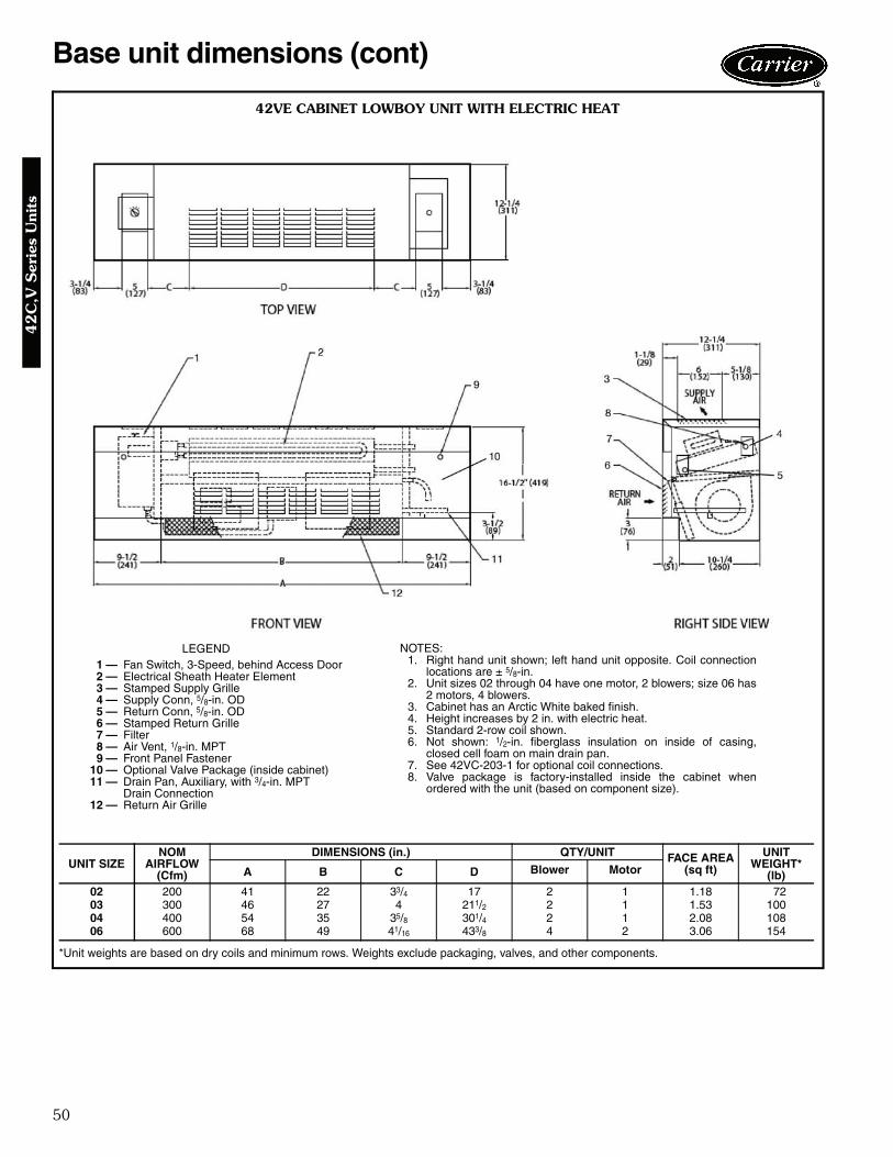
50
Base unit dimensions (cont)
42VE CABINET LOWBOY UNIT WITH ELECTRIC HEAT
*Unit weights are based on dry coils and minimum rows. Weights exclude packaging, valves, and other components.
UNIT SIZENOM
AIRFLOW(Cfm)
DIMENSIONS (in.) QTY/UNIT FACE AREA(sq ft)
UNIT WEIGHT*
(lb)A B C D Blower Motor
02 200 41 22 33/4 17 2 1 1.18 7203 300 46 27 4 211/2 2 1 1.53 10004 400 54 35 35/8 301/4 2 1 2.08 10806 600 68 49 41/16 433/8 4 2 3.06 154
LEGEND1 — Fan Switch, 3-Speed, behind Access Door2 — Electrical Sheath Heater Element3 — Stamped Supply Grille4 — Supply Conn, 5/8-in. OD5 — Return Conn, 5/8-in. OD6 — Stamped Return Grille7 — Filter8 — Air Vent, 1/8-in. MPT9 — Front Panel Fastener
10 — Optional Valve Package (inside cabinet)11 — Drain Pan, Auxiliary, with 3/4-in. MPT
Drain Connection12 — Return Air Grille
NOTES:1. Right hand unit shown; left hand unit opposite. Coil connection
locations are ± 5/8-in.2. Unit sizes 02 through 04 have one motor, 2 blowers; size 06 has
2 motors, 4 blowers.3. Cabinet has an Arctic White baked finish.4. Height increases by 2 in. with electric heat.5. Standard 2-row coil shown.6. Not shown: 1/2-in. fiberglass insulation on inside of casing,
closed cell foam on main drain pan.7. See 42VC-203-1 for optional coil connections.8. Valve package is factory-installed inside the cabinet when
ordered with the unit (based on component size).
A42-4115
42
C,V
Ser
ies
Uni
ts

51
42VG FURRED-IN WALL UNIT
LEGEND1 — Supply Conn, 5/8-in. OD2 — Air Vent, 1/8-in. MPT3 — Filter4 — Return Air Grille, Stamped5 — Stamped Supply Grille6 — Return Conn, 5/8-in. OD7 — Removable Front Panel8 — Drain Conn, 7/8-in. OD9 — Auxilary Drain Pan
10 — Valve Compartment11 — Junction Box
NOTES:1. Right hand unit shown; left hand unit opposite. Coil connection
locations are ± 5/8-in.2. Front panel has an Arctic White baked finish.3. Standard 2-row coil shown.4. Unit size 01 has one motor, one blower; size 03 has 2 motors,
2 blowers.5. Unit has 1/2-in. flanges for mounting to wall surface.6. Front panel hooks at top of unit, swing down and snap in at bottom
against a spring clip.7. Not shown: 3-speed fan switch, wall plate, 1/2-in. fiberglass insula-
tion on inside of casing, closed cell foam on main drain pan.
*Unit weights are based on dry coils and minimum rows. Weights exclude packaging, valves, and other components.
UNIT SIZENOM
AIRFLOW(Cfm)
DIMENSIONS (in.) QTY/UNIT UNIT WEIGHT*
(lb)A B C D E Blower Motor
01 150 253/4 153/4 14 11/2 123/4 1 1 4003 300 393/4 293/4 28 115/16 257/8 2 2 74
A42-4116
42
C,V
Series U
nits
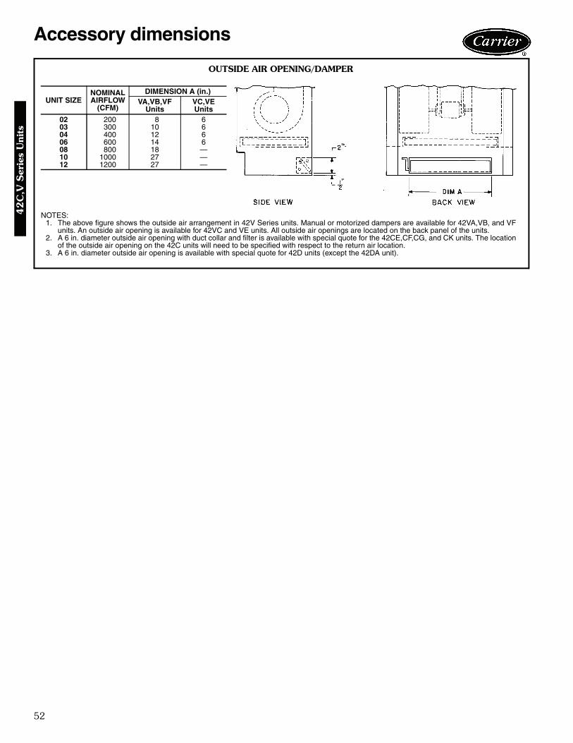
52
Accessory dimensions
OUTSIDE AIR OPENING/DAMPER
UNIT SIZENOMINAL AIRFLOW
(CFM)
DIMENSION A (in.)VA,VB,VF
UnitsVC,VE Units
02 200 8 603 300 10 604 400 12 606 600 14 608 800 18 —10 1000 27 —12 1200 27 —
NOTES:1. The above figure shows the outside air arrangement in 42V Series units. Manual or motorized dampers are available for 42VA,VB, and VF
units. An outside air opening is available for 42VC and VE units. All outside air openings are located on the back panel of the units.2. A 6 in. diameter outside air opening with duct collar and filter is available with special quote for the 42CE,CF,CG, and CK units. The location
of the outside air opening on the 42C units will need to be specified with respect to the return air location.3. A 6 in. diameter outside air opening is available with special quote for 42D units (except the 42DA unit).
42
C,V
Ser
ies
Uni
ts

53
42
C O
PTIO
NA
L C
OIL
CO
NN
EC
TIO
N L
OC
ATIO
N S
IZES 0
2–1
2
NO
TE
S:
1.R
ight
han
d un
it sh
own;
left
hand
uni
t opp
osite
.2.
All
dim
ensi
ons
are
in in
ches
±1 /
4 in
ch.
3.D
imen
sion
s do
not
app
ly to
uni
ts w
ith fa
ctor
y va
lve
pack
ages
.4.
All
conn
ectio
n si
zes
5 /8 i
n. O
D.
5.S
plit
coil
conn
ectio
ns
show
n ar
e fo
r 4-
pipe
co
mbi
natio
ns;
chill
ed/h
ot w
ater
coi
ls o
nly,
with
hot
wat
er c
oil
in s
tand
ard
rehe
at p
ositi
on.
CO
IL C
ON
NE
CT
ION
DIM
EN
SIO
NS
R I G H T H A N D
UN
ITS
IZE
3-R
OW
CO
IL4-
RO
W C
OIL
3 A
ND
1 S
PL
IT C
OIL
AB
CD
EF
GH
JK
LM
NP
Q02
43/ 4
25/ 8
41/ 4
41/ 4
35/ 8
41/ 4
55/ 1
621
/ 16
55/ 1
631
/ 841
/ 455
/ 811
/ 821
/ 16
41/ 4
0343
/ 425
/ 841
/ 441
/ 435
/ 841
/ 455
/ 16
21/ 1
655
/ 16
31/ 8
41/ 4
55/ 8
11/ 8
21/ 1
641
/ 404
43/ 4
25/ 8
41/ 4
41/ 4
35/ 8
41/ 4
55/ 1
621
/ 16
55/ 1
631
/ 841
/ 455
/ 811
/ 821
/ 16
41/ 4
0643
/ 425
/ 835
/ 847
/ 851
/ 247
/ 855
/ 16
21/ 1
655
/ 16
31/ 8
47/ 8
67/ 8
23/ 8
21/ 1
647
/ 808
43/ 4
25/ 8
35/ 8
47/ 8
35/ 8
41/ 4
55/ 1
621
/ 16
55/ 1
631
/ 847
/ 867
/ 823
/ 821
/ 16
47/ 8
1043
/ 425
/ 847
/ 835
/ 841
/ 447
/ 855
/ 16
21/ 1
655
/ 16
31/ 8
51/ 2
67/ 8
23/ 8
21/ 1
641
/ 412
43/ 4
25/ 8
47/ 8
35/ 8
41/ 4
47/ 8
55/ 1
621
/ 16
55/ 1
631
/ 851
/ 267
/ 823
/ 821
/ 16
41/ 4
R I G H T H A N D
UN
ITS
IZE
3 A
ND
2 S
PL
IT C
OIL
R I G H T H A N D
UN
ITS
IZE
4 A
ND
1 S
PL
IT C
OIL
JK
LM
NP
QJ
KL
MN
PQ
0265
/ 16
41/ 8
41/ 4
55/ 8
13/ 4
211 /
1641
/ 402
53/ 1
625
/ 841
/ 455
/ 811
/ 819
/ 16
41/ 4
0365
/ 16
41/ 8
41/ 4
55/ 8
13/ 4
211 /
1641
/ 403
55/ 1
625
/ 841
/ 455
/ 811
/ 819
/ 16
41/ 4
0465
/ 16
41/ 8
41/ 4
55/ 8
13/ 4
211 /
1641
/ 404
55/ 1
625
/ 841
/ 455
/ 811
/ 819
/ 16
41/ 4
0665
/ 16
41/ 8
47/ 8
67/ 8
321
1 /16
47/ 8
0655
/ 16
25/ 8
47/ 8
67/ 8
23/ 8
19/ 1
647
/ 808
65/ 1
641
/ 847
/ 867
/ 83
211 /
1647
/ 808
55/ 1
625
/ 847
/ 867
/ 823
/ 819
/ 16
47/ 8
1065
/ 16
41/ 8
51/ 2
67/ 8
321
1 /16
41/ 4
1055
/ 16
25/ 8
51/ 2
67/ 8
23/ 8
19/ 1
641
/ 412
65/ 1
641
/ 851
/ 267
/ 83
211 /
1647
/ 812
55/ 1
625
/ 851
/ 267
/ 823
/ 819
/ 16
41/ 4
L E F T H A N D
UN
ITS
IZE
3-R
OW
CO
IL4-
RO
W C
OIL
3 A
ND
1 S
PL
IT C
OIL
AB
CD
EF
GH
JK
LM
NP
Q02
43/ 4
25/ 8
41/ 4
41/ 4
41/ 4
35/ 8
55/ 1
621
/ 16
55/ 1
631
/ 835
/ 85
1 /2
21/ 1
635
/ 803
43/ 4
25/ 8
41/ 4
41/ 4
41/ 4
35/ 8
55/ 1
621
/ 16
55/ 1
631
/ 835
/ 85
1 /2
21/ 1
635
/ 804
43/ 4
25/ 8
41/ 4
41/ 4
41/ 4
35/ 8
55/ 1
621
/ 16
55/ 1
631
/ 835
/ 85
1 /2
21/ 1
635
/ 806
43/ 4
25/ 8
47/ 8
35/ 8
47/ 8
51/ 2
55/ 1
621
/ 16
55/ 1
631
/ 841
/ 463
/ 41 /
221
/ 16
41/ 4
0843
/ 425
/ 847
/ 835
/ 841
/ 435
/ 855
/ 16
21/ 1
655
/ 16
31/ 8
41/ 4
63/ 4
1 /2
21/ 1
641
/ 410
43/ 4
25/ 8
35/ 8
47/ 8
47/ 8
41/ 2
55/ 1
621
/ 16
55/ 1
631
/ 835
/ 863
/ 41 /
221
/ 16
47/ 8
1243
/ 425
/ 835
/ 847
/ 847
/ 841
/ 255
/ 16
21/ 1
655
/ 16
31/ 8
35/ 8
63/ 4
1 /2
21/ 1
647
/ 8
L E F T H A N D
UN
ITS
IZE
3 A
ND
2 S
PL
IT C
OIL
JK
LM
NP
Q02
65/ 1
641
/ 835
/ 85
11/ 8
211 /
1635
/ 803
65/ 1
641
/ 835
/ 85
11/ 8
211 /
1635
/ 804
65/ 1
641
/ 835
/ 85
11/ 8
211 /
1635
/ 806
65/ 1
641
/ 841
/ 463
/ 411
/ 821
1 /16
41/ 4
0865
/ 16
41/ 8
41/ 4
63/ 4
11/ 8
211 /
1641
/ 410
65/ 1
641
/ 835
/ 863
/ 411
/ 821
1 /16
47/ 8
1265
/ 16
41/ 8
35/ 8
63/ 4
11/ 8
211 /
1647
/ 8
L E F T H A N D
UN
ITS
IZE
4 A
ND
1 S
PL
IT C
OIL
JK
LM
NP
Q02
53/ 1
625
/ 835
/ 85
1 /2
19/ 1
635
/ 803
55/ 1
625
/ 835
/ 85
1 /2
19/ 1
635
/ 804
55/ 1
625
/ 835
/ 85
1 /2
19/ 1
635
/ 806
55/ 1
625
/ 841
/ 463
/ 41 /
219
/ 16
41/ 4
0855
/ 16
25/ 8
41/ 4
63/ 4
1 /2
19/ 1
641
/ 410
55/ 1
625
/ 835
/ 863
/ 41 /
219
/ 16
47/ 8
1255
/ 16
25/ 8
35/ 8
63/ 4
1 /2
19/ 1
647
/ 8
42
C,V
Series U
nits

54
Accessory dimensions (cont)42VA
,VB
,VF
OPTIO
NA
L C
OIL
CO
NN
EC
TIO
N L
OC
ATIO
N S
IZES
02–1
2
a42-3994
NO
TE
S:
1.D
imen
sion
s fo
r sp
lit c
oils
with
opp
osite
end
con
nect
ions
will
var
y.2.
Coi
l con
nect
ion
dim
ensi
ons
are
for
coils
stu
b ou
ts o
nly.
Val
ve p
acka
ges
not i
nclu
ded.
3.A
ll di
men
sion
s ar
e in
inch
es.
4.S
plit
coil
conn
ectio
ns s
how
n ar
e fo
r 4-
pipe
com
bina
tions
; chi
lled/
hot w
ater
coi
ls o
nly,
with
hot
wat
er c
oil i
n st
anda
rd r
ehea
t pos
ition
.
CO
IL C
ON
NE
CT
ION
DIM
EN
SIO
NS
L E F T H A N D
UN
ITS
IZE
3-R
OW
CO
IL4-
RO
W C
OIL
3 A
ND
1 S
PL
IT C
OIL
AB
CD
EF
GH
JK
LM
NP
RS
024
515 /
1617
1 /16
181 /
831
/ 461
/ 217
7 /16
185 /
831
/ 445
/ 853
/ 16
73/ 4
167 /
1617
7 /16
181 /
221
7 /8
034
515 /
1617
1 /16
181 /
831
/ 461
/ 217
7 /16
185 /
831
/ 445
/ 853
/ 16
73/ 4
167 /
1617
7 /16
181 /
221
7 /8
044
515 /
1617
1 /16
181 /
831
/ 461
/ 217
7 /16
185 /
831
/ 445
/ 853
/ 16
73/ 4
167 /
1617
7 /16
181 /
221
7 /8
0631
/ 16
55/ 8
175 /
818
11/ 1
631
/ 261
/ 416
7 /8
191 /
831
/ 245
/ 851
/ 273
/ 416
7 /16
167 /
818
217 /
8
083
55/ 8
183 /
418
11/ 1
629
/ 16
57/ 8
181 /
219
5 /8
27/ 8
315 /
1647
/ 871
/ 817
1 /2
1819
1 /8
2310
311 /
165
175 /
819
3 /4
27/ 8
63/ 1
618
191 /
831
/ 431
5 /16
41/ 2
71/ 8
171 /
217
7 /16
195 /
823
1231
1 /16
517
5 /8
193 /
427
/ 863
/ 16
1819
1 /8
31/ 4
315 /
1641
/ 271
/ 817
1 /2
177 /
1619
5 /8
23
L E F T H A N D
UN
ITS
IZE
3 A
ND
2 S
PL
IT C
OIL
4 A
ND
1 S
PL
IT C
OIL
JK
LM
NP
RS
JK
LM
NP
RS
024
651
/ 283
/ 816
7 /16
167 /
817
7 /16
185 /
831
/ 26
61/ 4
917
1 /8
167 /
819
1 /8
221 /
2
034
651
/ 283
/ 816
7 /16
167 /
817
7 /16
185 /
831
/ 26
61/ 4
917
1 /8
167 /
819
1 /8
221 /
2
044
651
/ 283
/ 816
7 /16
167 /
817
7 /16
185 /
831
/ 26
61/ 4
917
1 /8
167 /
819
1 /8
221 /
2
0631
1 /16
653
/ 16
81/ 8
167 /
1617
7 /16
167 /
819
1 /8
31/ 4
61/ 4
61/ 2
917
1 /8
177 /
1618
5 /8
221 /
2
083
653
/ 16
71/ 2
171 /
217
7 /16
181 /
219
5 /8
27/ 8
51/ 2
59/ 1
69
171 /
818
203 /
1622
1 /2
1031
1 /16
66
63/ 4
171 /
218
1819
1 /8
31/ 4
53/ 4
57/ 8
917
1 /8
177 /
1619
5 /8
221 /
2
1231
1 /16
66
63/ 4
171 /
218
1819
1 /8
31/ 4
53/ 4
57/ 8
917
1 /8
177 /
1619
5 /8
221 /
2
CO
IL C
ON
NE
CT
ION
DIM
EN
SIO
NS
R I G H T H A N D
UN
ITS
IZE
3-R
OW
CO
IL4-
RO
W C
OIL
3 A
ND
1 S
PL
IT C
OIL
AB
CD
EF
GH
JK
LM
NP
RS
024
515 /
1617
1 /16
181 /
831
/ 261
/ 416
7 /8
191 /
839
/ 16
47/ 8
51/ 2
815
7 /8
167 /
818
211 /
4
034
515 /
1617
1 /16
181 /
831
/ 261
/ 416
7 /8
191 /
839
/ 16
47/ 8
51/ 2
815
7 /8
167 /
818
211 /
4
044
515 /
1617
1 /16
181 /
831
/ 261
/ 416
7 /8
191 /
839
/ 16
47/ 8
51/ 2
815
7 /8
167 /
818
211 /
4
0631
1 /16
55/ 8
175 /
818
11/ 1
631
/ 461
/ 217
7 /16
185 /
831
/ 447
/ 853
/ 16
815
7 /8
177 /
1618
1 /2
211 /
4
0831
1 /16
517
5 /8
193 /
427
/ 859
/ 16
1820
3 /16
31/ 4
47/ 8
53/ 1
68
157 /
817
7 /16
181 /
221
1 /4
1031
/ 16
55/ 8
183 /
418
11/ 1
631
/ 457
/ 817
7 /16
195 /
827
/ 847
/ 86
815
7 /8
1818
1 /8
211 /
4
1231
/ 16
55/ 8
183 /
418
11/ 1
631
/ 457
/ 817
7 /16
195 /
827
/ 847
/ 86
815
7 /8
1818
1 /8
211 /
4
R I G H T H A N D
UN
ITS
IZE
3 A
ND
2 S
PL
IT C
OIL
4 A
ND
1 S
PL
IT C
OIL
JK
LM
NP
RS
JK
LM
NP
RS
024
71/ 4
51/ 2
83/ 8
167 /
1616
7 /8
177 /
1618
5 /8
31/ 2
661
/ 473
/ 416
7 /16
167 /
1619
1 /8
217 /
8
034
71/ 4
51/ 2
83/ 8
167 /
1616
7 /8
177 /
1618
5 /8
31/ 2
661
/ 473
/ 416
7 /16
167 /
1619
1 /8
217 /
8
044
71/ 4
51/ 2
83/ 8
167 /
1616
7 /8
177 /
1618
5 /8
31/ 2
661
/ 473
/ 416
7 /16
167 /
1619
1 /8
217 /
8
0631
1 /16
53/ 4
53/ 1
681
/ 816
7 /16
177 /
1616
7 /8
191 /
831
/ 461
/ 461
/ 273
/ 416
7 /16
167 /
1618
5 /8
217 /
8
083
81/ 1
653
/ 16
71/ 2
171 /
217
7 /16
181 /
219
5 /8
27/ 8
51/ 2
59/ 1
681
/ 817
1 /2
1820
3 /16
2310
311 /
1673
/ 86
63/ 4
171 /
218
1819
1 /8
31/ 4
53/ 4
57/ 8
81/ 2
171 /
217
7 /16
195 /
823
1231
1 /16
73/ 8
663
/ 417
1 /2
1818
191 /
831
/ 453
/ 457
/ 881
/ 217
1 /2
177 /
1619
5 /8
23
42
C,V
Ser
ies
Uni
ts

55
42VC,VE OPTIONAL COIL CONNECTION LOCATION SIZES 02–06
NOTES:1. Dimensions for split coils with opposite end
connections will vary.2. Coil connection diemsnions are for coils stub
outs only (valve packages not included).3. All dimensions are in inches.4. Split coil connections shown are for 4-pipe
combinations; chilled/hot water coils only,with hot water coil in standard reheat position.
COIL CONNECTION DIMENSIONS
UNITSIZE
2-ROW COIL 3-ROW COIL 2 AND 1 SPLIT COILA B C D E F G H J K L M N P R S
RIGHT
HAND
02 1 103/8 107/16 111/4 15/16 10 83/8 121/2 7/8 115/16 101/8 93/4 91/2 109/16 101/4 123/803 1 103/8 107/16 111/4 15/16 10 83/8 121/2 7/8 15/16 101/8 93/4 91/2 109/16 101/4 123/804 1 103/8 107/16 111/4 11/2 93/4 815/16 117/8 7/8 15/16 101/8 93/4 91/2 109/16 101/4 123/806 11/4 10 10 113/4 11/2 93/4 815/16 117/8 11/4 15/16 93/4 93/4 815/16 109/16 103/4 123/8
LEFT
HAND
02 11/4 103/16 91/4 123/8 15/16 10 83/8 121/2 11/16 115/16 10 103/8 103/8 101/2 113/8 123/803 11/4 103/16 91/4 123/8 15/16 10 83/8 121/2 11/16 15/16 10 103/8 83/8 101/2 113/8 123/804 11/4 103/16 91/4 123/8 11/4 10 10 103/4 11/16 115/16 10 103/8 83/8 101/2 113/8 123/806 17/16 10 10 113/4 11/4 10 10 103/4 11/4 115/16 93/4 107/16 815/16 101/2 103/4 123/8
42
C,V
Series U
nits
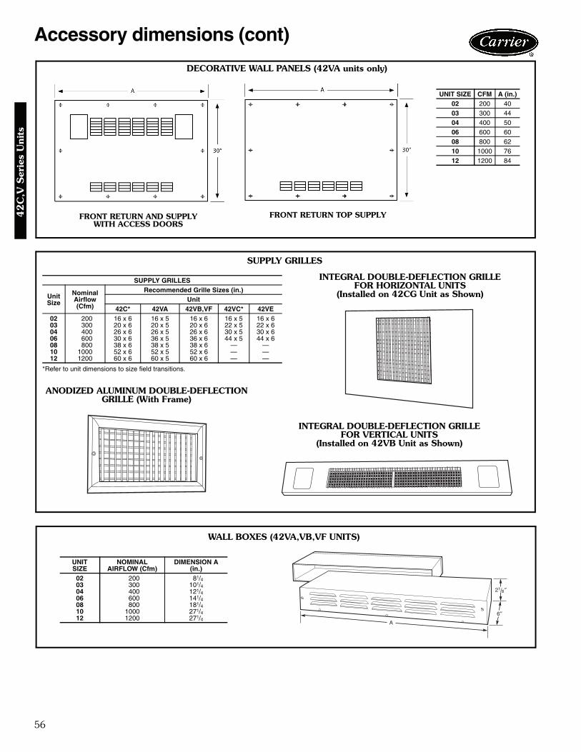
56
Accessory dimensions (cont)
DECORATIVE WALL PANELS (42VA units only)
SUPPLY GRILLES
*Refer to unit dimensions to size field transitions.
SUPPLY GRILLES
UnitSize
NominalAirflow(Cfm)
Recommended Grille Sizes (in.)Unit
42C* 42VA 42VB,VF 42VC* 42VE02 200 16 x 6 16 x 5 16 x 6 16 x 5 16 x 603 300 20 x 6 20 x 5 20 x 6 22 x 5 22 x 604 400 26 x 6 26 x 5 26 x 6 30 x 5 30 x 606 600 30 x 6 36 x 5 36 x 6 44 x 5 44 x 608 800 38 x 6 38 x 5 38 x 6 — —10 1000 52 x 6 52 x 5 52 x 6 — —12 1200 60 x 6 60 x 5 60 x 6 — —
INTEGRAL DOUBLE-DEFLECTION GRILLEFOR HORIZONTAL UNITS
(Installed on 42CG Unit as Shown)
INTEGRAL DOUBLE-DEFLECTION GRILLEFOR VERTICAL UNITS
(Installed on 42VB Unit as Shown)
ANODIZED ALUMINUM DOUBLE-DEFLECTIONGRILLE (With Frame)
WALL BOXES (42VA,VB,VF UNITS)
UNITSIZE
NOMINALAIRFLOW (Cfm)
DIMENSION A(in.)
02 200 81/403 300 101/404 400 121/406 600 141/408 800 181/410 1000 271/412 1200 271/4
UNIT SIZE CFM A (in.)02 200 4003 300 4404 400 5006 600 6008 800 6210 1000 7612 1200 84
FRONT RETURN AND SUPPLY WITH ACCESS DOORS
FRONT RETURN TOP SUPPLY
A42-4117
A42-4118
8
A42-4119
42
C,V
Ser
ies
Uni
ts
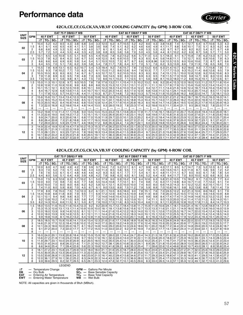
57
42CA,CE,CF,CG,CK,VA,VB,VF COOLING CAPACITY (by GPM) 3-ROW COIL
42CA,CE,CF,CG,CK,VA,VB,VF COOLING CAPACITY (by GPM) 4-ROW COIL
LEGEND
NOTE: All capacities are given in thousands of Btuh (MBtuh).
UNITSIZE GPM
EAT 75 F DB/63 F WB EAT 80 F DB/67 F WB EAT 85 F DB/71 F WB40 F EWT 45 F EWT 50 F EWT 40 F EWT 45 F EWT 50 F EWT 40 F EWT 45 F EWT 50 F EWT
ΔT TCb SCb ΔT TCb SCb ΔT TCb SCb ΔT TCb SCb ΔT TCb SCb ΔT TCb SCb ΔT TCb SCb ΔT TCb TCb ΔT TCb SCb
02
1 10.4 5.2 4.2 8.5 4.3 3.8 6.8 3.4 3.3 12.5 6.2 4.7 10.5 5.2 4.2 8.6 4.3 3.8 14.8 7.4 5.1 12.7 6.4 4.7 10.6 5.3 4.31.5 8.1 6.1 4.6 6.5 4.9 4.1 5.1 3.8 3.6 9.8 7.4 5.1 8.2 6.2 4.6 6.6 4.9 4.1 11.7 8.8 5.6 10.1 7.5 5.1 8.3 6.2 4.62 6.6 6.6 4.9 5.3 5.3 4.3 4.0 4.0 3.7 8.1 8.1 5.4 6.7 6.7 4.8 5.3 5.3 4.3 9.7 9.7 6.0 8.2 8.2 5.4 6.7 6.7 4.8
2.5 5.7 7.2 5.0 4.4 5.5 4.4 3.3 4.2 3.8 6.8 8.5 5.6 5.6 7.0 5.0 4.5 5.6 4.4 8.1 10.2 6.2 6.9 8.7 5.6 5.7 7.1 5.0
031 13.1 6.5 5.6 10.9 5.5 5.1 9.0 4.5 4.4 15.6 7.8 6.2 13.2 6.6 5.7 11.0 5.5 5.1 18.3 9.1 6.7 15.8 7.9 6.2 13.3 6.7 5.7
1.5 10.3 7.8 6.2 8.4 6.3 5.6 6.7 5.0 4.9 12.5 9.4 6.9 10.5 7.9 6.3 8.5 6.4 5.6 14.8 11.1 7.5 12.7 9.5 6.9 10.6 7.9 6.32 8.6 8.6 6.6 6.9 6.9 5.9 5.4 5.4 5.1 10.5 10.5 7.3 8.7 8.7 6.6 6.9 6.96 5.9 12.5 12.5 8.0 10.6 10.6 7.3 8.7 8.7 6.63 6.4 9.5 7.0 5.1 7.6 6.2 3.9 5.8 5.4 7.8 11.7 7.8 6.4 9.7 7.0 5.1 7.6 6.2 9.3 13.9 8.6 7.9 11.9 7.8 6.5 9.8 7.0
04
1 15.5 7.8 6.9 13.1 6.5 6.2 10.7 5.4 5.3 18.4 9.2 7.6 15.7 7.8 7.0 13.2 6.6 6.3 21.4 10.7 8.2 18.6 9.3 7.7 15.8 7.9 7.11.5 12.5 9.3 7.8 10.2 7.7 7.0 8.3 6.2 6.1 15.0 11.2 8.6 12.6 9.4 7.8 10.3 7.7 7.1 17.7 13.3 9.3 15.2 11.4 8.6 12.6 9.5 7.92 10.5 10.5 8.3 8.5 8.5 7.4 6.7 6.7 6.5 12.7 12.7 9.2 10.5 10.5 8.3 8.5 8.5 7.4 15.1 15.1 10.0 12.8 12.8 9.2 10.6 10.6 8.33 7.9 11.8 8.9 6.3 9.5 7.9 4.8 7.3 6.9 9.6 14.5 9.9 8.0 12.0 8.9 6.3 9.5 7.9 11.5 17.3 10.9 9.8 14.7 9.9 8.0 12.0 8.9
3.5 7.0 12.3 9.1 5.6 9.8 8.1 4.3 7.5 7.0 8.6 15.1 10.2 7.1 12.5 9.1 5.6 9.8 8.1 10.3 18.0 11.2 8.8 15.3 10.1 7.2 12.6 9.1
06
1.5 15.0 11.3 10.1 12.9 9.7 9.0 10.5 7.8 7.8 17.6 13.2 11.1 15.4 11.5 10.2 13.2 9.9 9.2 20.4 15.3 12.0 18.0 13.5 11.2 15.7 11.8 10.42 12.8 12.8 11.0 10.9 10.9 9.9 8.8 8.8 8.8 15.3 15.3 12.1 13.1 13.1 11.2 11.1 11.1 10.1 17.9 17.9 13.1 15.6 15.6 12.2 13.4 13.4 11.33 10.1 15.1 12.1 8.3 12.5 10.9 6.8 10.1 9.6 12.2 18.3 13.4 10.3 15.4 12.2 9.4 12.7 11.1 14.4 21.6 14.6 12.4 18.7 13.4 10.4 15.6 12.34 8.4 16.7 12.9 6.8 13.6 11.5 5.4 10.7 10.1 10.2 20.3 14.3 8.5 17.0 12.9 6.8 13.6 11.5 12.1 24.1 15.6 10.3 20.7 14.2 8.5 17.1 12.95 7.1 17.8 13.3 5.7 14.3 11.8 4.4 11.1 10.3 8.7 21.7 14.8 7.2 18.0 13.3 5.7 14.3 11.9 10.3 25.8 16.2 8.8 22.0 14.7 7.3 18.1 13.3
08
2 15.6 15.6 13.7 13.4 13.4 12.3 10.8 10.8 10.8 18.3 18.3 15.0 15.9 15.9 13.9 13.6 13.6 12.5 21.2 21.2 16.2 18.7 18.7 15.2 16.3 16.3 14.13 12.3 18.5 15.2 10.3 15.5 13.8 8.5 12.7 12.0 14.7 22.1 16.8 12.5 18.8 15.4 10.4 15.7 14.0 17.3 26.0 18.2 15.0 22.5 16.9 12.7 19.0 15.54 10.3 20.5 16.2 8.4 16.9 14.6 6.8 13.5 12.8 12.4 24.7 17.9 10.4 20.8 16.3 8.5 16.9 14.7 14.2 28.4 19.5 12.6 25.2 17.9 10.5 20.9 16.36 7.3 22.0 16.9 6.2 18.6 15.4 4.8 14.4 13.5 9.3 28.0 19.3 7.8 23.3 17.4 6.2 18.6 15.5 11.1 33.4 21.1 9.5 28.5 19.2 7.8 23.5 17.48 — — — — — — — — — — — — — — — — — — — — — — — — — — —
10
3 13.2 19.8 17.5 11.4 17.1 15.8 9.0 13.5 13.5 15.5 23.2 19.1 13.6 20.4 17.8 11.7 17.6 16.1 18.0 27.0 20.7 15.9 23.9 19.4 14.0 20.9 18.14 11.3 22.6 19.0 9.6 19.2 17.2 7.5 15.1 15.1 13.5 26.9 20.9 11.6 23.1 19.2 9.8 19.6 17.5 15.8 31.6 22.5 13.8 27.6 21.1 11.8 23.6 19.55 9.9 24.7 20.0 8.3 20.6 18.1 6.8 17.0 15.9 11.9 29.7 22.0 10.1 25.3 20.2 8.4 21.0 18.4 14.0 35.0 23.9 12.2 30.4 22.2 10.3 25.7 20.46 8.8 26.4 20.8 7.3 21.8 18.8 5.9 17.7 16.5 10.6 31.9 23.0 9.0 27.0 21.0 7.4 22.2 19.0 12.6 37.8 25.0 10.9 32.7 23.1 9.1 27.4 21.18 7.2 29.0 22.0 5.9 23.7 19.7 4.6 18.6 17.2 8.8 35.3 24.4 7.4 29.7 22.1 6.0 23.8 19.8 10.5 41.9 26.6 9.0 36.2 24.4 7.5 30.0 22.1
12
3 14.9 22.4 19.9 12.9 19.4 17.9 10.2 15.3 15.3 17.4 26.2 22.0 15.4 23.1 20.3 13.3 20.0 18.3 20.2 30.3 23.8 18.0 27.0 22.4 15.8 23.8 20.64 12.8 25.7 21.9 11.0 22.0 19.9 8.6 17.2 17.2 15.2 30.4 24.0 13.2 26.3 22.3 11.2 22.5 20.1 17.7 35.5 26.0 15.6 31.1 24.3 13.5 26.9 22.65 11.3 28.1 23.1 9.5 23.7 21.0 7.8 19.6 18.3 13.4 33.6 25.4 11.5 28.8 23.4 9.7 24.2 21.3 15.8 39.5 27.6 13.8 34.4 25.7 11.7 29.3 23.76 10.1 30.2 24.2 8.3 25.0 21.8 6.8 20.5 19.1 12.1 36.3 26.6 10.3 30.8 24.4 8.5 25.5 22.0 14.3 42.9 28.6 12.4 37.1 26.7 10.4 31.2 24.58 8.3 33.2 25.6 6.8 27.3 22.9 5.4 21.6 20.1 10.1 40.3 28.3 8.5 34.0 25.7 6.9 27.5 23.1 11.9 47.8 30.8 10.3 41.3 28.4 8.6 34.3 25.7
UNITSIZE GPM
EAT 75 F DB/63 F WB EAT 80 F DB/67 F WB EAT 85 F DB/71 F WB40 F EWT 45 F EWT 50 F EWT 40 F EWT 45 F EWT 50 F EWT 40 F EWT 45 F EWT 50 F EWT
ΔT TCb SCb ΔT TCb SCb ΔT TCb SCb ΔT TCb SCb ΔT TCb SCb ΔT TCb SCb ΔT TCb SCb ΔT TCb TCb ΔT TCb SCb
02
1 12.0 6.0 4.7 9.8 4.9 4.2 7.8 3.9 3.7 14.4 7.2 5.2 12.1 6.1 4.7 9.9 4.9 4.3 17.1 8.5 5.7 14.7 7.3 5.2 12.3 6.1 4.81.5 9.3 7.0 5.2 7.5 5.7 4.6 5.8 4.4 4.0 11.3 8.5 5.8 9.5 7.1 5.2 7.6 5.7 4.6 13.5 10.1 6.3 11.6 8.7 5.8 9.6 7.2 5.22 7.6 7.6 5.5 6.1 6.1 4.8 4.6 4.6 4.2 9.3 9.3 6.1 7.7 7.7 5.4 6.1 6.1 4.8 11.1 11.1 6.7 9.5 9.5 6.1 7.8 7.8 5.4
2.5 6.4 8.0 5.6 5.1 6.4 4.9 3.9 4.8 4.2 7.8 9.8 6.3 6.5 8.1 5.6 5.2 6.4 4.9 9.4 11.7 7.0 8.0 10.0 6.3 6.6 8.3 5.6
031 15.0 7.5 6.3 12.6 6.3 5.7 10.2 5.1 5.0 17.9 9.0 6.9 15.2 7.6 6.4 12.6 6.3 5.8 21.0 10.5 7.5 18.2 9.1 7.0 15.3 7.7 6.4
1.5 12.0 9.0 7.0 9.8 7.3 6.3 7.7 5.8 5.5 14.4 10.8 7.7 12.1 9.1 7.0 9.8 7.4 6.3 17.1 12.8 8.4 14.7 11.0 7.7 12.2 9.1 7.02 10.0 10.0 7.5 8.0 8.0 6.6 6.2 6.2 5.8 12.1 12.1 8.3 10.0 10.0 7.4 8.0 8.0 6.6 14.3 14.3 9.1 12.2 12.2 8.2 10.1 10.1 7.43 7.4 11.0 8.0 5.9 8.9 7.0 4.5 6.7 6.1 9.0 13.5 8.9 7.5 11.2 7.9 5.9 8.9 7.0 10.8 16.1 9.8 9.2 13.8 8.8 7.6 11.4 7.9
04
1 17.9 8.9 7.8 15.0 7.5 7.0 12.3 6.2 6.1 21.1 10.5 8.5 18.0 9.0 7.8 15.1 7.6 7.0 24.5 12.2 9.2 21.3 10.6 8.6 18.2 9.1 7.91.5 14.4 10.8 8.8 11.8 8.9 7.9 9.5 7.1 6.9 17.2 12.9 9.6 14.5 10.9 8.8 11.9 8.9 7.9 20.3 15.2 10.5 17.5 13.1 9.6 14.6 10.9 8.82 12.1 12.1 9.4 9.8 9.8 8.3 7.7 7.7 7.3 14.6 14.6 10.4 12.2 12.2 9.4 9.8 9.8 8.4 17.4 17.4 11.3 14.8 14.8 10.3 12.2 12.2 9.43 9.2 13.8 10.2 7.4 11.0 8.9 5.6 8.4 7.8 11.2 16.8 11.3 9.3 13.9 10.1 7.4 11.1 9.0 13.3 20.0 12.4 11.4 17.0 11.2 9.3 14.0 10.1
3.5 8.2 14.3 10.4 6.6 11.5 9.1 5.0 8.7 7.9 10.0 17.5 11.6 8.3 14.5 10.4 6.6 11.5 9.1 11.9 20.9 12.8 10.2 17.8 11.5 8.4 14.7 10.3
06
1.5 18.0 13.5 11.6 15.5 11.6 10.4 12.3 9.2 9.2 20.9 15.7 12.7 18.4 13.8 11.7 15.9 11.9 10.6 24.1 18.1 13.6 21.4 16.1 12.8 18.9 14.1 11.92 15.3 15.3 12.6 13.1 13.1 11.4 10.9 10.9 10.0 18.1 18.1 13.8 15.6 15.6 12.7 13.3 13.3 11.6 21.1 21.1 14.9 18.5 18.5 13.9 16.0 16.0 12.93 12.0 18.0 13.9 9.9 14.9 12.5 8.1 12.1 11.1 14.4 21.6 15.4 12.2 18.3 14.0 10.1 15.1 12.6 17.0 25.5 16.7 14.7 22.0 15.4 12.4 18.5 14.04 12.0 18.0 13.9 9.9 14.9 12.5 8.1 12.1 11.1 14.4 21.6 15.4 12.2 18.3 14.0 10.1 15.1 12.6 17.0 25.5 16.7 14.7 22.0 15.4 12.4 18.5 14.05 9.9 19.8 14.8 8.1 16.2 13.2 6.4 12.8 11.6 12.0 23.9 16.4 10.0 20.1 14.8 8.1 16.3 13.2 14.2 28.4 17.9 12.2 24.4 16.3 10.1 20.3 14.7
08
2 18.5 18.5 15.7 15.9 15.9 14.1 13.4 13.4 12.3 21.6 21.6 17.1 18.9 18.9 15.8 16.3 16.3 14.3 24.9 24.9 18.4 22.0 22.0 17.2 19.3 19.3 15.93 14.6 21.9 17.5 12.3 18.4 15.8 10.2 15.2 14.0 17.3 26.0 19.2 14.9 22.3 17.6 12.4 18.6 15.9 20.3 30.4 20.8 17.7 26.5 19.2 15.0 22.5 17.74 12.1 24.3 18.6 10.0 20.0 16.7 8.1 16.2 14.8 14.6 29.2 20.6 12.3 24.6 18.6 10.1 20.2 16.8 17.2 34.4 22.4 14.8 29.6 20.5 12.4 24.8 18.76 9.1 27.2 20.0 7.3 22.0 17.7 5.7 17.2 15.5 11.0 33.0 22.2 9.2 27.6 19.9 7.4 22.2 17.7 13.1 39.2 24.3 11.2 33.6 22.1 9.3 27.8 19.98 — — — — — — — — — — — — — — — — — — — — — — — — — — —
10
3 16.0 24.0 20.1 13.9 20.8 18.4 10.6 15.9 15.9 18.7 28.0 22.1 16.4 24.7 20.4 14.3 21.5 18.7 21.6 32.4 23.8 19.2 28.8 22.3 17.0 25.5 20.84 13.6 27.2 21.9 11.6 23.2 19.9 9.7 19.5 17.6 16.1 32.3 24.0 14.0 27.9 22.1 11.9 23.8 20.3 18.8 37.7 25.9 16.5 33.1 24.1 14.3 28.5 22.45 11.9 29.7 23.1 10.0 24.9 20.9 8.2 20.5 18.5 14.2 35.5 25.4 12.1 30.4 23.3 10.2 25.4 21.1 16.7 41.7 27.6 14.5 36.3 25.5 12.4 31.0 23.46 10.5 31.6 24.0 8.8 26.3 21.6 7.1 21.3 19.2 12.7 38.1 26.5 10.8 32.3 24.1 8.9 26.7 21.8 15.0 45.0 28.9 13.0 39.0 26.5 11.0 32.9 24.28 8.6 34.6 25.4 7.1 28.4 22.6 5.6 22.3 19.8 10.5 41.8 28.2 8.8 35.3 25.4 7.1 28.6 22.6 12.4 49.6 30.8 10.7 43.0 28.1 8.9 35.8 25.4
12
3 18.1 27.2 23.1 15.8 23.7 20.9 12.0 18.0 18.0 21.1 31.6 25.3 18.7 28.0 23.4 16.4 24.6 21.3 24.2 36.3 27.2 21.7 32.5 25.6 19.3 29.0 23.94 15.5 30.9 25.3 13.3 26.6 23.0 11.3 22.5 20.3 18.2 36.5 27.7 15.9 31.8 25.6 13.7 27.4 23.4 21.2 42.3 29.8 18.7 37.3 27.8 16.3 32.6 25.95 13.5 33.8 26.8 11.5 28.6 24.3 9.6 23.9 21.5 16.1 40.2 29.4 13.8 34.6 27.0 11.7 29.3 24.5 18.8 47.1 31.8 16.5 41.1 29.5 14.1 35.4 27.26 12.0 36.1 27.9 10.1 30.2 25.2 8.3 24.9 22.3 14.4 43.3 30.7 12.3 36.9 28.0 10.2 30.7 25.4 17.0 50.9 33.3 14.8 44.3 30.7 12.5 37.5 28.18 9.9 39.6 29.5 8.2 32.7 26.5 6.5 26.1 23.3 12.0 47.8 32.7 10.1 40.5 29.6 8.3 33.0 26.5 14.3 57.1 35.9 12.3 49.1 32.7 10.3 41.0 29.6
ΔT — Temperature Change GPM — Gallons Per MinuteDB — Dry Bulb SCb — Base Sensible CapacityEAT — Entering Air Temperature TCb — Base Total CapacityEWT — Entering Water Temperature WB — Wet Bulb
Performance data4
2C
,V S
eries Units
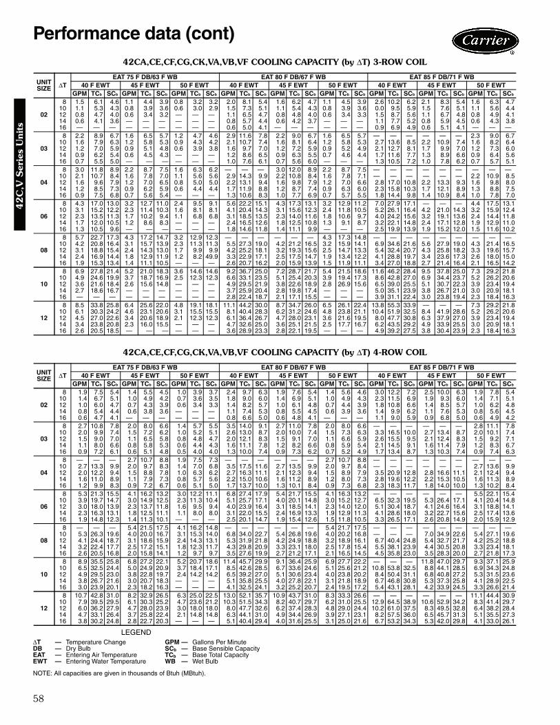
58
42CA,CE,CF,CG,CK,VA,VB,VF COOLING CAPACITY (by ΔT) 3-ROW COIL
42CA,CE,CF,CG,CK,VA,VB,VF COOLING CAPACITY (by ΔT) 4-ROW COIL
LEGEND
NOTE: All capacities are given in thousands of Btuh (MBtuh).
UNITSIZE ΔT
EAT 75 F DB/63 F WB EAT 80 F DB/67 F WB EAT 85 F DB/71 F WB40 F EWT 45 F EWT 50 F EWT 40 F EWT 45 F EWT 50 F EWT 40 F EWT 45 F EWT 50 F EWT
GPM TCb SCb GPM TCb SCb GPM TCb SCb GPM TCb SCb GPM TCb SCb GPM TCb SCb GPM TCb SCb GPM TCb SCb GPM TCb SCb
02
8 1.5 6.1 4.6 1.1 4.4 3.9 0.8 3.2 3.2 2.0 8.1 5.4 1.6 6.2 4.7 1.1 4.5 3.9 2.6 10.2 6.2 2.1 8.3 5.4 1.6 6.3 4.710 1.1 5.3 4.3 0.8 3.9 3.6 0.6 3.0 2.9 1.5 7.3 5.1 1.1 5.4 4.3 0.8 3.9 3.6 0.0 9.5 5.9 1.5 7.6 5.1 1.1 5.6 4.412 0.8 4.7 4.0 0.6 3.4 3.2 — — — 1.1 6.5 4.7 0.8 4.8 4.0 0.6 3.4 3.3 1.5 8.7 5.6 1.1 6.7 4.8 0.8 4.9 4.114 0.6 4.1 3.6 — — — — — — 0.8 5.7 4.4 0.6 4.2 3.7 — — — 1.1 7.7 5.2 0.8 5.9 4.5 0.6 4.3 3.816 — — — — — — — — — 0.6 5.0 4.1 — — — — — — 0.9 6.9 4.9 0.6 5.1 4.1 — — —
03
8 2.2 8.9 6.7 1.6 6.5 5.7 1.2 4.7 4.6 2.9 11.6 7.8 2.2 9.0 6.7 1.6 6.5 5.7 — — — — — — 2.3 9.0 6.710 1.6 7.9 6.3 1.2 5.8 5.3 0.9 4.3 4.2 2.1 10.7 7.4 1.6 8.1 6.4 1.2 5.8 5.3 2.7 13.6 8.5 2.2 10.9 7.4 1.6 8.2 6.412 1.2 7.0 5.9 0.9 5.1 4.8 0.6 3.9 3.8 1.6 9.7 7.0 1.2 7.2 5.9 0.9 5.2 4.9 2.1 12.7 8.1 1.7 9.9 7.0 1.2 7.3 6.014 0.9 6.2 5.4 0.6 4.5 4.3 — — — 1.2 8.6 6.5 0.9 6.3 5.5 0.7 4.6 4.4 1.7 11.6 7.7 1.3 8.9 6.6 0.9 6.4 5.616 0.7 5.5 5.0 — — — — — — 1.0 7.6 6.1 0.7 5.6 6.0 — — — 1.3 10.5 7.2 1.0 7.8 6.2 0.7 5.7 5.1
04
8 3.0 11.8 8.9 2.2 8.7 7.5 1.6 6.3 6.2 — — — 3.0 12.0 8.9 2.2 8.7 7.5 — — — — — — — — —10 2.1 10.7 8.4 1.6 7.8 7.0 1.1 5.6 5.6 2.9 14.3 9.9 2.2 10.8 8.4 1.6 7.8 7.1 — — — — — — 2.2 10.9 8.512 1.6 9.6 7.9 1.2 7.0 6.5 0.8 5.0 5.0 2.2 13.1 9.4 1.6 9.8 7.9 1.2 7.0 6.6 2.8 17.0 10.8 2.2 13.3 9.3 1.6 9.8 8.014 1.2 8.5 7.3 0.9 6.2 5.9 0.6 4.4 4.4 1.7 11.9 8.8 1.2 8.7 7.4 0.9 6.3 6.0 2.3 15.8 10.3 1.7 12.1 8.9 1.3 8.8 7.516 0.9 7.5 6.8 0.7 5.6 5.4 — — — 1.3 10.6 8.3 1.0 7.7 6.9 0.7 5.7 5.5 1.8 14.4 9.8 1.4 10.9 8.4 1.0 7.8 7.0
06
8 4.3 17.0 13.0 3.2 12.7 11.0 2.4 9.5 9.1 5.6 22.2 15.1 4.3 17.3 13.1 3.2 12.9 11.2 7.0 27.9 17.1 — — — 4.4 17.5 13.110 3.1 15.2 12.2 2.3 11.4 10.3 1.6 8.1 8.1 4.1 20.4 14.3 3.1 15.6 12.3 2.4 11.8 10.5 5.2 26.1 16.4 4.2 21.0 14.3 3.2 15.9 12.412 2.3 13.5 11.3 1.7 10.2 9.4 1.1 6.8 6.8 3.1 18.5 13.5 2.3 14.0 11.6 1.8 10.6 9.7 4.0 24.2 15.6 3.2 19.1 13.6 2.4 14.4 11.814 1.7 12.0 10.5 1.2 8.6 8.3 — — — 2.4 16.5 12.6 1.8 12.5 10.8 1.3 9.1 8.7 3.2 22.1 14.8 2.4 17.1 12.8 1.9 12.9 11.016 1.3 10.5 9.6 — — — — — — 1.8 14.6 11.8 1.4 11.1 9.9 — — — 2.5 19.9 13.9 1.9 15.2 12.0 1.5 11.6 10.2
08
8 5.7 22.7 17.3 4.3 17.2 14.7 3.2 12.9 12.3 — — — — — — 4.3 17.3 14.8 — — — — — — — — —10 4.2 20.8 16.4 3.1 15.7 13.9 2.3 11.3 11.3 5.5 27.3 19.0 4.2 21.2 16.5 3.2 15.9 14.1 6.9 34.6 21.6 5.6 27.9 19.0 4.3 21.4 16.512 3.1 18.8 15.4 2.4 14.3 13.0 1.7 9.9 9.9 4.2 25.2 18.1 3.2 19.3 15.6 2.5 14.7 13.3 5.4 32.4 20.7 4.3 25.8 18.2 3.3 19.6 15.714 2.4 16.9 14.4 1.8 12.9 11.9 1.2 8.2 49.9 3.3 22.9 17.1 2.5 17.5 14.7 1.9 13.4 12.2 4.1 28.8 19.7 3.4 23.6 17.3 2.6 18.0 15.016 1.9 15.3 13.4 1.4 11.1 10.5 — — — 2.6 20.7 16.2 2.0 15.9 13.9 1.5 11.9 11.1 3.4 27.0 18.8 2.7 21.4 16.4 2.1 16.5 14.2
10
8 6.9 27.8 21.4 5.2 21.0 18.3 3.6 14.6 14.6 9.2 36.7 25.0 7.2 28.7 21.7 5.4 21.5 18.6 11.6 46.2 28.4 9.5 37.8 25.0 7.3 29.2 21.810 4.9 24.6 19.9 3.7 18.7 16.9 2.5 12.3 12.3 6.6 33.1 23.5 5.1 25.4 20.3 3.9 19.4 17.3 8.6 42.8 27.0 6.9 34.4 23.7 5.2 26.2 20.612 3.6 21.6 18.4 2.6 15.6 14.8 — — — 4.9 29.5 21.9 3.8 22.6 18.9 2.8 26.9 15.6 6.5 39.0 25.5 5.1 30.7 22.3 3.9 23.4 19.414 2.7 18.6 16.7 — — — — — — 3.7 25.9 20.4 2.8 19.8 17.4 — — — 5.0 35.1 23.9 3.8 26.7 21.0 3.0 20.9 18.116 — — — — — — — — — 2.8 22.4 18.7 2.1 17.1 15.5 — — — 3.9 31.1 22.4 3.0 23.8 19.4 2.3 18.4 16.3
12
8 8.5 33.8 25.8 6.4 25.6 22.0 4.8 19.1 18.1 11.1 44.2 30.0 8.7 34.7 26.0 6.5 26.1 22.4 13.8 55.3 33.9 — — — 7.3 29.2 21.810 6.1 30.3 24.2 4.6 23.1 20.6 3.1 15.5 15.5 8.1 40.4 28.3 6.2 31.2 24.6 4.8 23.8 21.1 10.4 51.9 32.5 8.4 41.9 28.6 5.2 26.2 20.612 4.5 27.0 22.6 3.4 20.6 18.9 2.1 12.3 12.3 6.1 36.4 26.7 4.7 28.0 23.1 3.6 21.6 19.5 8.0 47.7 30.8 6.3 37.9 27.0 3.9 23.4 19.414 3.4 23.8 20.8 2.3 16.0 15.5 — — — 4.7 32.6 25.0 3.6 25.1 21.5 2.5 17.7 16.7 6.2 43.5 29.2 4.9 33.9 25.5 3.0 20.9 18.116 2.6 20.5 18.5 — — — — — — 3.6 28.9 23.3 2.8 22.1 19.5 — — — 4.9 39.2 27.5 3.8 30.4 23.9 2.3 18.4 16.3
UNITSIZE ΔT
EAT 75 F DB/63 F WB EAT 80 F DB/67 F WB EAT 85 F DB/71 F WB40 F EWT 45 F EWT 50 F EWT 40 F EWT 45 F EWT 50 F EWT 40 F EWT 45 F EWT 50 F EWT
GPM TCb SCb GPM TCb SCb GPM TCb SCb GPM TCb SCb GPM TCb SCb GPM TCb SCb GPM TCb SCb GPM TCb SCb GPM TCb SCb
02
8 1.9 7.5 5.4 1.4 5.5 4.5 1.0 3.9 3.7 2.4 9.7 6.3 1.9 7.6 5.4 1.4 5.6 4.6 3.0 12.2 7.2 2.5 10.0 6.3 1.9 7.8 5.410 1.4 6.7 5.1 1.0 4.9 4.2 0.7 3.6 3.5 1.8 9.0 6.0 1.4 6.9 5.1 1.0 4.9 4.3 2.3 11.5 6.9 1.9 9.3 6.0 1.4 7.1 5.112 1.0 6.0 4.7 0.7 4.3 3.9 0.6 3.4 3.3 1.4 8.2 5.7 1.0 6.1 4.8 0.7 4.4 3.9 1.8 10.8 6.6 1.4 8.5 5.7 1.0 6.2 4.814 0.8 5.4 4.4 0.6 3.8 3.6 — — — 1.1 7.4 5.3 0.8 5.5 4.5 0.6 3.9 3.6 1.4 9.9 6.2 1.1 7.6 5.3 0.8 5.6 4.516 0.6 4.7 4.1 — — — — — — 0.8 6.6 5.0 0.6 4.8 4.1 — — — 1.1 9.0 5.9 0.9 6.8 5.0 0.6 4.9 4.2
03
8 2.7 10.8 7.8 2.0 8.0 6.6 1.4 5.7 5.5 3.5 14.0 9.1 2.7 11.0 7.8 2.0 8.0 6.6 — — — — — — 2.8 11.1 7.810 2.0 9.9 7.4 1.5 7.2 6.2 1.0 5.2 5.1 2.6 13.0 8.7 2.0 10.0 7.4 1.5 7.3 6.3 3.3 16.5 10.0 2.7 13.4 8.7 2.0 10.1 7.412 1.5 9.0 7.0 1.1 6.5 5.8 0.8 4.8 4.7 2.0 12.1 8.3 1.5 9.1 7.0 1.1 6.6 5.9 2.6 15.5 9.5 2.1 12.4 8.3 1.5 9.2 7.114 1.1 8.0 6.6 0.8 5.8 5.3 0.6 4.4 4.3 1.6 11.1 7.8 1.2 8.2 6.6 0.8 5.9 5.4 2.1 14.5 9.1 1.6 11.4 7.9 1.2 8.3 6.716 0.9 7.2 6.1 0.6 5.1 4.8 0.5 4.0 4.0 1.3 10.0 7.4 0.9 7.3 6.2 0.7 5.2 4.9 1.7 13.4 8.7 1.3 10.3 7.4 0.9 7.4 6.3
04
8 — — — 2.7 10.7 8.8 1.9 7.5 7.3 — — — — — — 2.7 10.7 8.8 — — — — — — — — —10 2.7 13.3 9.9 2.0 9.7 8.3 1.4 7.0 6.8 3.5 17.5 11.6 2.7 13.5 9.9 2.0 9.7 8.4 — — — — — — 2.7 13.6 9.912 2.0 12.2 9.4 1.5 8.8 7.8 1.0 6.3 6.2 2.7 16.3 11.1 2.1 12.3 9.4 1.5 8.9 7.9 3.5 20.9 12.8 2.8 16.6 11.1 2.1 12.4 9.414 1.6 11.0 8.9 1.1 7.9 7.3 0.8 5.7 5.6 2.2 15.0 10.6 1.6 11.2 8.9 1.2 8.0 7.3 2.8 19.6 12.2 2.2 15.3 10.5 1.6 11.3 8.916 1.2 9.9 8.3 0.9 7.2 6.7 0.6 5.1 5.0 1.7 13.7 10.0 1.3 10.1 8.4 0.9 7.3 6.8 2.3 18.3 11.7 1.8 14.0 10.0 1.3 10.2 8.4
06
8 5.3 21.3 15.5 4.1 16.2 13.2 3.0 12.2 11.1 6.8 27.4 17.9 5.4 21.7 15.5 4.1 16.3 13.2 — — — — — — 5.5 22.1 15.410 3.9 19.7 14.7 3.0 14.9 12.5 2.3 11.3 10.4 5.1 25.7 17.1 4.0 20.1 14.8 3.0 15.2 12.7 6.5 32.3 19.5 5.3 26.4 17.1 4.1 20.4 14.812 3.0 18.0 13.9 2.3 13.7 11.8 1.6 9.5 9.4 4.0 23.9 16.4 3.1 18.5 14.1 2.3 14.0 12.0 5.1 30.4 18.7 4.1 24.6 16.4 3.1 18.8 14.114 2.3 16.3 13.1 1.8 12.5 11.1 1.1 8.0 8.0 3.1 22.0 15.5 2.4 16.9 13.3 1.9 12.9 11.3 4.1 28.6 18.0 3.2 22.7 15.6 2.5 17.4 13.616 1.9 14.8 12.3 1.4 11.3 10.1 — — — 2.5 20.1 14.7 1.9 15.4 12.6 1.5 11.8 10.5 3.3 26.5 17.1 2.6 20.8 14.9 2.0 15.9 12.9
08
8 — — — 5.4 21.5 17.5 4.1 16.2 14.8 — — — — — — 5.4 21.7 17.5 — — — — — — — — —10 5.3 26.3 19.6 4.0 20.0 16.7 3.1 15.3 14.0 6.8 34.0 22.7 5.4 26.8 19.6 4.0 20.2 16.8 — — — 7.0 34.9 22.6 5.4 27.1 19.612 4.1 24.4 18.7 3.1 18.6 15.9 2.4 14.3 13.1 5.3 31.9 21.8 4.2 24.9 18.8 3.2 18.9 16.1 6.7 40.4 24.8 5.4 32.7 21.7 4.2 25.2 18.814 3.2 22.4 17.7 2.5 17.2 15.1 1.8 12.3 11.7 4.3 29.8 20.9 3.3 23.1 18.0 2.5 17.8 15.4 5.5 38.1 23.9 4.4 30.5 20.8 3.3 23.4 18.116 2.6 20.5 16.8 2.0 15.8 14.1 1.2 9.7 9.7 3.5 27.6 19.9 2.7 21.2 17.1 2.1 16.5 14.5 4.5 35.8 23.0 3.5 28.3 20.0 2.7 21.8 17.3
10
8 8.9 35.5 25.8 6.8 27.2 22.1 5.2 20.7 18.6 11.4 45.7 29.9 9.1 36.4 25.9 6.9 27.7 22.2 — — — 11.8 47.0 29.7 9.3 37.1 25.910 6.5 32.5 24.4 5.0 24.9 20.9 3.7 18.4 17.1 8.5 42.6 28.5 6.7 33.6 24.6 5.1 25.6 21.2 10.8 53.8 32.5 8.8 44.1 28.5 6.9 34.3 24.812 4.9 29.5 23.0 3.8 22.8 19.7 2.4 14.2 14.2 6.5 39.2 27.0 5.1 30.6 23.4 4.0 23.8 20.2 8.4 50.4 31.1 6.8 40.8 27.2 5.3 31.5 23.614 3.8 26.7 21.6 3.0 20.7 18.3 — — — 5.1 35.8 25.5 4.0 27.8 22.1 3.1 21.8 18.9 6.7 46.8 30.8 5.3 37.3 25.8 4.1 28.9 22.516 3.0 23.9 20.1 2.3 18.2 16.3 — — — 4.1 32.5 24.1 3.2 25.2 20.7 2.4 19.5 17.2 5.4 43.1 28.1 4.2 33.9 24.5 3.3 26.6 21.4
12
8 10.7 42.8 31.0 8.2 32.9 26.5 6.3 25.0 22.5 13.0 52.1 35.7 10.9 43.7 31.0 8.3 33.3 26.6 — — — — — — 11.1 44.4 30.910 7.9 39.5 29.5 6.1 30.3 25.2 4.7 23.6 21.2 10.3 51.5 34.3 8.2 40.7 29.7 6.2 31.0 25.5 12.9 64.5 38.9 10.6 52.9 34.2 8.3 41.4 29.712 6.0 36.2 27.9 4.7 28.0 23.9 3.0 18.0 18.0 8.0 47.7 32.6 6.2 37.4 28.3 4.8 29.0 24.4 10.2 61.0 37.5 8.3 49.5 32.8 6.4 38.2 28.414 4.7 33.1 26.4 3.7 25.8 22.4 2.1 14.8 14.8 6.3 44.1 31.0 4.9 34.4 26.9 3.9 27.1 23.1 8.2 57.5 36.0 6.5 45.7 31.3 5.1 35.5 27.316 3.8 30.2 24.8 2.8 22.7 20.3 — — — 5.1 40.4 29.4 4.0 31.6 25.5 3.1 25.0 21.6 6.7 53.2 34.3 5.3 42.0 29.8 4.1 33.0 26.1
ΔT — Temperature Change GPM — Gallons Per MinuteDB — Dry Bulb SCb — Base Sensible CapacityEAT — Entering Air Temperature TCb — Base Total CapacityEWT — Entering Water Temperature WB — Wet Bulb
Performance data (cont)4
2C
,V S
erie
s U
nits

59
42VC,VE,VG COOLING CAPACITY (by GPM) 2-ROW COIL
42VC,VE,VG COOLING CAPACITY (by GPM) 3-ROW COIL
42VC,VE,VG COOLING CAPACITY (by ΔT) 2-ROW COIL
LEGEND NOTE: All capacities are given in thousands of Btuh (MBtuh).
UNITSIZE GPM
EAT 75 F DB/63 F WB EAT 80 F DB/67 F WB EAT 85 F DB/71 F WB40 F EWT 45 F EWT 50 F EWT 40 F EWT 45 F EWT 50 F EWT 40 F EWT 45 F EWT 50 F EWT
ΔT TCb SCb ΔT TCb SCb ΔT TCb SCb ΔT TCb SCb ΔT TCb SCb ΔT TCb SCb ΔT TCb SCb ΔT TCb TCb ΔT TCb SCb
02
1 9.5 4.8 3.9 7.8 3.9 3.5 6.2 3.1 3.1 11.5 5.8 4.3 9.7 4.8 3.9 7.8 3.9 3.6 13.7 6.8 4.7 11.7 5.9 4.3 9.8 4.9 4.01.5 7.4 5.6 4.3 6.0 4.5 3.8 4.6 3.5 3.3 9.1 6.8 4.7 7.5 5.6 4.3 6.0 4.5 3.8 10.8 8.1 5.2 9.3 7.0 4.7 7.6 5.7 4.32 6.1 6.1 4.5 4.8 4.8 4.0 3.7 3.7 3.4 7.4 7.4 5.0 6.1 6.1 4.5 4.8 4.8 4.0 8.9 8.9 5.5 7.6 7.6 5.0 6.2 6.2 4.5
2.5 4.4 6.6 4.7 3.5 5.2 4.1 2.6 3.9 3.6 5.4 8.1 5.3 4.5 6.7 4.7 3.5 5.3 4.1 6.4 9.7 5.8 5.5 8.3 5.3 4.5 6.8 4.7
031 12.0 6.0 5.2 9.9 5.0 4.7 8.1 4.0 4.0 14.4 7.2 5.7 12.1 6.1 5.2 10.0 5.0 4.7 17.0 8.5 6.2 14.6 7.3 5.8 12.2 6.1 5.3
1.5 9.5 7.1 5.7 7.7 5.8 5.1 6.1 4.6 4.5 11.5 8.7 6.3 9.6 7.2 5.8 7.7 5.8 5.2 13.8 10.3 6.9 11.7 8.8 6.4 9.7 7.3 5.82 7.9 7.9 6.1 6.3 6.3 5.4 4.9 4.9 4.7 9.7 9.7 6.8 8.0 8.0 6.1 6.3 6.3 5.4 11.6 11.6 7.4 9.8 9.8 6.7 8.0 8.0 6.13 5.8 8.8 6.5 4.6 7.0 5.7 3.5 5.2 4.9 7.2 10.7 7.2 5.9 8.9 6.5 4.6 7.0 5.7 8.6 12.9 8.0 7.3 11.0 7.2 6.0 9.0 6.4
04
1 14.9 7.5 6.6 12.5 6.2 6.0 10.3 5.1 5.1 17.7 8.8 7.3 15.1 7.5 6.7 12.6 6.3 6.0 20.7 10.3 7.9 17.9 9.0 7.4 15.2 7.6 6.71.5 11.9 9.0 7.4 9.8 7.3 6.6 7.9 5.9 5.8 14.4 10.8 8.2 12.1 9.1 7.5 9.8 7.4 6.7 17.1 12.8 8.9 14.6 11.0 8.2 12.1 9.1 7.52 10.0 10.0 7.9 8.1 8.1 7.0 6.3 6.3 6.1 12.2 12.2 8.8 10.1 10.1 7.9 8.1 8.1 7.1 14.5 14.5 9.6 12.3 12.3 8.7 10.1 10.1 7.93 7.5 11.3 8.5 6.0 9.0 7.5 4.6 6.9 6.5 9.2 13.9 9.5 7.6 11.4 8.5 6.0 9.0 7.5 11.0 16.6 10.4 9.4 14.1 9.4 7.7 11.5 8.5
3.5 0.0 11.8 8.7 5.3 9.3 7.6 4.0 7.1 6.6 8.2 14.4 9.7 6.8 11.9 8.7 5.3 9.3 7.7 9.9 17.2 10.7 8.4 14.7 9.6 6.9 12.0 8.6
06
1.5 17.1 8.6 8.1 14.6 7.3 7.3 12.1 6.1 6.1 20.0 10.0 9.1 17.6 8.8 8.2 14.9 7.4 7.4 23.0 11.5 9.9 20.5 10.3 9.2 18.0 9.0 8.32 12.3 12.3 10.5 10.3 10.3 9.5 8.5 8.5 8.2 14.7 14.7 11.6 12.5 12.5 10.6 10.5 10.5 9.6 17.3 17.3 12.6 14.9 14.9 11.6 12.7 12.7 10.83 9.7 14.5 11.6 7.9 11.9 10.4 6.4 9.5 9.1 11.7 17.6 12.8 9.8 14.8 11.7 8.0 12.0 10.5 14.0 20.9 14.0 12.0 18.0 12.9 10.0 15.0 11.74 8.0 16.0 12.3 6.5 13.0 10.9 5.1 10.1 9.5 9.8 19.6 13.6 8.2 16.3 12.3 6.5 13.0 11.0 11.7 23.3 14.9 10.0 20.0 13.6 8.2 16.4 12.35 5.9 17.8 13.1 4.7 14.2 11.5 3.6 10.8 10.0 7.3 21.8 14.6 6.0 18.1 13.0 4.7 14.2 11.5 8.7 26.1 16.0 7.4 22.2 14.5 6.1 18.3 13.0
UNITSIZE GPM
EAT 75 F DB/63 F WB EAT 80 F DB/67 F WB EAT 85 F DB/71 F WB40 F EWT 45 F EWT 50 F EWT 40 F EWT 45 F EWT 50 F EWT 40 F EWT 45 F EWT 50 F EWT
ΔT TCb SCb ΔT TCb SCb ΔT TCb SCb ΔT TCb SCb ΔT TCb SCb ΔT TCb SCb ΔT TCb SCb ΔT TCb TCb ΔT TCb SCb
02
1 11.8 5.9 4.7 9.7 4.8 4.2 7.7 3.8 3.7 14.3 7.2 5.2 12.0 6.0 4.7 9.7 4.9 4.2 17.0 8.5 5.6 14.5 7.3 5.2 12.1 6.1 4.71.5 9.2 6.9 5.1 7.4 5.6 4.5 5.7 4.3 3.9 11.2 8.4 5.7 9.4 7.0 5.1 7.5 5.6 4.5 13.4 10.0 6.3 11.5 8.6 5.7 9.5 7.1 5.12 7.5 7.5 5.4 6.0 6.0 4.7 4.5 4.5 4.1 9.2 9.2 6.0 7.6 7.6 5.4 6.0 6.0 4.7 11.0 11.0 6.7 9.4 9.4 6.0 7.7 7.7 5.3
2.5 5.4 8.1 5.7 4.3 6.5 4.9 3.2 4.9 4.2 6.6 10.0 6.4 5.5 8.3 5.7 4.4 6.6 4.9 8.0 12.0 7.1 6.8 10.3 6.3 5.6 8.5 5.6
031 14.9 7.4 6.2 12.3 6.2 5.6 10.0 5.0 4.9 17.8 8.9 6.8 15.0 7.5 6.3 12.4 6.2 5.7 20.9 10.4 7.4 18.0 9.0 6.9 15.1 7.6 6.3
1.5 11.8 8.9 6.9 9.6 7.2 6.2 7.6 5.7 5.4 14.3 10.8 7.7 12.0 9.0 6.9 9.7 7.2 6.2 17.0 12.8 8.4 14.6 10.9 7.7 12.0 9.0 7.02 9.8 9.8 7.4 7.9 7.9 6.5 6.1 6.1 5.7 12.0 12.0 8.2 9.9 9.9 7.3 7.9 7.9 6.5 14.3 14.3 9.0 12.2 12.2 8.1 10.0 10.0 7.33 7.3 10.9 7.9 5.8 8.8 6.9 4.4 6.6 6.0 8.9 13.4 8.8 7.4 11.1 7.8 5.9 8.8 6.9 10.7 16.0 9.7 9.1 13.7 8.7 7.5 11.2 7.8
04
1 17.1 8.5 7.5 14.7 7.4 6.7 11.9 5.9 5.9 19.9 10.0 8.3 17.5 8.7 7.6 15.1 7.6 6.9 22.9 11.5 8.9 20.4 10.2 8.4 18.0 9.0 7.71.5 13.8 10.4 8.5 11.7 8.8 7.7 9.8 7.3 6.8 16.4 12.3 9.4 14.1 10.6 8.6 12.0 9.0 7.9 19.2 14.4 10.1 16.8 12.6 9.4 14.4 10.8 8.72 11.7 11.7 9.2 9.7 9.7 8.3 7.9 7.9 7.3 14.1 14.1 10.1 12.0 12.0 9.3 9.9 9.9 8.4 16.6 16.6 11.0 14.4 14.4 10.1 12.2 12.2 9.33 9.0 13.5 10.0 7.4 11.0 8.9 5.8 8.7 7.8 11.0 16.4 11.2 9.2 13.8 10.0 7.5 11.2 9.0 13.0 19.6 12.2 11.2 16.9 11.1 9.4 14.1 10.1
3.5 0.0 14.7 10.6 5.9 11.9 9.3 4.6 9.1 8.1 9.0 17.9 11.8 7.5 15.0 10.5 6.0 12.0 9.3 10.7 21.4 13.0 9.2 18.4 11.7 7.6 15.2 10.5
06
1.5 22.1 11.1 9.9 19.2 9.6 8.8 15.3 7.6 7.6 25.7 12.8 10.9 22.7 11.4 10.0 19.7 9.8 8.9 29.2 14.6 11.8 26.3 13.1 11.0 23.3 11.7 10.12 15.8 15.8 12.8 13.4 13.4 11.6 11.2 11.2 10.2 18.7 18.7 14.1 16.1 16.1 13.0 13.6 13.6 11.7 21.8 21.8 15.2 19.1 19.1 14.2 16.4 16.4 13.13 12.4 18.5 14.2 10.2 15.3 12.7 8.2 12.4 11.2 14.9 22.3 15.7 12.6 18.9 14.2 10.3 15.5 12.8 17.6 26.4 17.1 15.2 22.8 15.7 12.7 19.1 14.34 10.2 20.4 15.1 8.3 16.6 13.4 6.5 13.0 11.7 12.3 24.7 16.7 10.4 20.8 15.0 8.4 16.7 13.4 14.7 29.4 18.3 12.6 25.2 16.6 10.5 21.0 15.05 7.5 22.5 16.0 6.0 18.1 14.1 4.6 13.9 12.2 9.2 27.5 17.9 7.6 22.9 16.0 6.1 18.3 14.1 10.9 32.8 19.7 9.4 28.1 17.8 7.7 23.2 15.9
UNITSIZE ΔT
EAT 75 F DB/63 F WB EAT 80 F DB/67 F WB EAT 85 F DB/71 F WB40 F EWT 45 F EWT 50 F EWT 40 F EWT 45 F EWT 50 F EWT 40 F EWT 45 F EWT 50 F EWT
GPM TCb SCb GPM TCb SCb GPM TCb SCb GPM TCb SCb GPM TCb SCb GPM TCb SCb GPM TCb SCb GPM TCb SCb GPM TCb SCb
02
8 1.3 5.3 4.2 1.0 3.8 3.5 0.7 2.9 2.8 1.8 7.2 4.9 1.4 5.5 4.2 1.0 3.9 3.5 2.3 9.2 5.6 1.9 7.4 4.9 1.4 5.6 4.210 0.9 4.6 3.8 0.7 3.3 3.1 0.5 2.6 2.6 1.3 6.4 4.6 0.9 4.7 3.9 0.7 3.4 3.2 1.7 8.5 5.3 1.3 6.6 4.6 1.0 4.8 3.912 0.7 4.0 3.5 — — — — — — 0.9 5.6 4.2 0.7 4.1 3.6 — — — 1.3 7.6 5.0 1.0 5.8 4.3 0.7 4.2 3.614 — — — — — — — — — 0.7 4.9 3.9 — — — — — — 1.0 6.7 4.6 0.7 5.0 4.0 0.5 3.6 3.316 — — — — — — — — — 0.5 4.1 3.6 — — — — — — 0.7 5.9 4.3 0.5 4.3 3.7 — — —
03
8 2.0 7.8 6.1 1.4 5.7 5.1 1.0 4.1 4.0 2.6 10.4 7.1 2.0 7.9 6.1 1.4 5.7 5.1 3.3 13.1 8.1 2.7 10.6 7.1 2.0 8.0 6.110 1.4 6.9 5.6 0.9 4.7 4.5 0.7 3.6 3.6 1.9 9.5 6.7 1.4 7.0 5.7 1.0 5.0 4.7 2.5 12.2 7.7 1.9 9.7 6.7 1.4 7.1 5.712 1.0 6.0 5.2 0.7 4.2 4.0 0.5 3.2 3.2 1.4 8.4 6.2 1.0 6.1 5.3 0.7 4.4 4.2 1.9 11.3 7.3 1.5 8.7 6.3 1.0 6.2 5.414 0.8 5.2 4.7 0.5 3.6 3.6 — — — 1.1 7.4 5.8 0.8 5.4 4.8 0.5 3.7 3.7 1.5 10.2 6.9 1.1 7.6 5.9 0.8 5.5 4.916 0.6 4.5 4.2 — — — — — — 0.8 6.5 5.3 0.6 4.6 4.3 — — — 1.1 9.0 6.4 0.8 6.6 5.4 0.6 4.7 4.4
04
8 2.8 11.1 8.4 2.0 8.1 7.1 1.5 5.8 5.8 — — — 2.8 11.2 8.4 2.0 8.1 7.1 — — — — — — 2.8 11.3 8.410 2.0 10.0 7.9 1.5 7.2 6.6 1.0 5.2 5.2 2.7 13.4 9.3 2.0 10.2 7.9 1.5 7.3 6.7 3.4 17.2 10.6 2.7 13.7 9.3 2.0 10.2 8.012 1.5 8.9 7.4 1.1 6.4 6.1 0.8 4.6 4.6 2.1 12.3 8.8 1.5 9.1 7.5 1.1 6.5 6.2 2.7 16.0 10.2 2.1 12.5 8.8 1.5 9.1 7.514 1.1 7.9 6.9 0.8 5.8 5.6 0.6 4.1 4.1 1.6 11.1 8.3 1.2 8.1 7.0 0.8 5.9 5.7 2.1 14.8 9.7 1.6 11.3 8.3 1.2 8.2 7.016 0.9 7.0 6.3 0.7 5.2 5.1 — — — 1.2 9.9 7.8 0.9 7.1 6.4 0.7 5.3 5.2 1.7 13.5 9.2 1.3 10.1 7.8 0.9 7.2 6.5
06
8 4.0 16.0 12.3 3.0 11.8 10.4 2.2 8.8 8.4 5.3 21.2 14.3 4.1 16.4 12.4 3.0 12.0 10.5 6.7 26.6 16.3 5.4 21.7 14.3 4.2 16.6 12.410 2.9 14.2 11.5 2.1 10.5 9.6 1.5 7.5 7.5 3.9 19.3 13.5 2.9 14.6 11.6 2.2 10.8 9.8 5.0 25.0 15.6 4.0 20.0 13.6 3.0 14.9 11.712 2.1 12.5 10.6 1.6 9.3 8.7 1.0 6.2 6.2 2.9 17.3 12.7 2.2 12.9 10.8 1.6 9.6 9.0 3.8 23.0 14.8 3.0 17.9 12.9 2.2 13.3 11.014 1.6 10.9 9.7 1.1 7.7 7.6 — — — 2.2 15.4 11.9 1.6 11.4 10.0 1.2 8.1 7.9 3.0 20.9 13.9 2.3 15.9 12.0 1.7 11.8 10.316 1.2 9.4 8.7 — — — — — — 1.7 13.5 11.0 1.2 9.9 9.0 — — — 2.3 18.7 13.1 1.8 14.0 11.2 1.3 10.4 9.4
ΔT — Temperature Change GPM — Gallons Per MinuteDB — Dry Bulb SCb — Base Sensible CapacityEAT — Entering Air Temperature TCb — Base Total CapacityEWT — Entering Water Temperature WB — Wet Bulb
42
C,V
Series U
nits
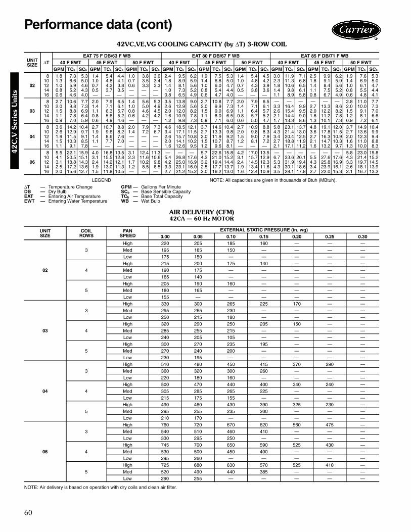
60
42VC,VE,VG COOLING CAPACITY (by ΔT) 3-ROW COIL
LEGEND NOTE: All capacities are given in thousands of Btuh (MBtuh).
AIR DELIVERY (CFM)42CA — 60 Hz MOTOR
NOTE: Air delivery is based on operation with dry coils and clean air filter.
UNITSIZE ΔT
EAT 75 F DB/63 F WB EAT 80 F DB/67 F WB EAT 85 F DB/71 F WB40 F EWT 45 F EWT 50 F EWT 40 F EWT 45 F EWT 50 F EWT 40 F EWT 45 F EWT 50 F EWT
GPM TCb SCb GPM TCb SCb GPM TCb SCb GPM TCb SCb GPM TCb SCb GPM TCb SCb GPM TCb SCb GPM TCb SCb GPM TCb SCb
02
8 1.8 7.3 5.3 1.4 5.4 4.4 1.0 3.8 3.6 2.4 9.5 6.2 1.9 7.5 5.3 1.4 5.4 4.5 3.0 11.9 7.1 2.5 9.9 6.2 1.9 7.6 5.310 1.3 6.6 5.0 1.0 4.8 4.1 0.7 3.5 3.4 1.8 8.9 5.9 1.4 6.8 5.0 1.0 4.8 4.2 2.3 11.3 6.8 1.8 9.1 5.9 1.4 6.9 5.012 1.0 5.9 4.6 0.7 4.2 3.8 0.6 3.3 3.3 1.4 8.1 5.6 1.0 6.0 4.7 0.7 4.3 3.9 1.8 10.6 6.5 1.4 8.4 5.6 1.0 6.1 4.714 0.8 5.2 4.3 0.5 3.7 3.5 — — — 1.0 7.3 5.2 0.8 5.4 4.4 0.5 3.8 3.6 1.4 9.8 6.1 1.1 7.5 5.2 0.8 5.5 4.416 0.6 4.6 4.0 — — — — — — 0.8 6.5 4.9 0.6 4.7 4.0 — — — 1.1 8.9 5.8 0.8 6.7 4.9 0.6 4.8 4.1
03
8 2.7 10.6 7.7 2.0 7.9 6.5 1.4 5.6 5.3 3.5 13.8 9.0 2.7 10.8 7.7 2.0 7.9 6.5 — — — — — — 2.8 11.0 7.710 2.0 9.8 7.3 1.4 7.1 6.1 1.0 5.0 4.9 2.6 12.9 5.6 2.0 9.9 7.3 1.4 7.1 6.1 3.3 16.4 9.9 2.7 13.3 8.6 2.0 10.0 7.312 1.5 8.8 6.9 1.1 6.3 5.7 0.8 4.6 4.5 2.0 12.0 8.2 1.5 9.0 6.9 1.1 6.4 5.7 2.6 15.4 9.5 2.0 12.2 8.2 1.5 9.1 7.014 1.1 7.8 6.4 0.8 5.6 5.2 0.6 4.2 4.2 1.6 10.9 7.8 1.1 8.0 6.5 0.8 5.7 5.2 2.1 14.4 9.0 1.6 11.2 7.8 1.2 8.1 6.616 0.9 7.0 5.9 0.6 4.9 4.6 — — — 1.2 9.8 7.3 0.9 7.1 6.0 0.6 5.0 4.7 1.7 13.3 8.6 1.3 10.1 7.3 0.9 7.2 6.1
04
8 3.6 14.2 10.4 2.7 10.7 8.8 2.0 7.9 7.3 4.6 18.5 12.1 3.7 14.6 10.4 2.7 10.9 8.8 5.8 23.1 13.7 4.8 19.1 12.0 3.7 14.9 10.410 2.6 12.9 9.7 1.9 9.6 8.2 1.4 7.2 6.7 3.4 17.1 11.5 2.7 13.3 9.8 2.0 9.8 8.3 4.3 21.4 13.0 3.6 17.8 11.5 2.7 13.6 9.912 1.9 11.5 9.1 1.4 8.6 7.6 — — — 2.6 15.7 10.8 2.0 11.9 9.2 1.5 9.0 7.9 3.4 20.4 12.5 2.7 16.3 10.9 2.0 12.3 9.414 1.5 10.3 8.5 1.1 7.7 7.0 — — — 2.0 14.1 10.2 1.5 10.7 8.7 1.2 8.1 7.2 2.7 18.8 11.9 2.1 14.7 10.3 1.6 11.0 8.816 1.1 9.1 7.8 — — — — — — 1.6 12.6 9.5 1.2 9.6 8.1 — — — 2.1 17.1 11.2 1.6 13.2 9.7 1.3 10.0 8.3
06
8 5.5 22.1 15.9 4.0 16.8 13.5 3.1 12.4 11.3 — — — 5.7 22.6 15.8 4.2 17.0 13.5 — — — — — — 5.8 23.0 15.810 4.1 20.5 15.1 3.1 15.5 12.8 2.3 11.6 10.6 5.4 26.8 17.6 4.2 21.0 15.2 3.1 15.7 12.9 6.7 33.6 20.1 5.5 27.6 17.6 4.3 21.4 15.212 3.1 18.8 14.3 2.4 14.2 12.1 1.7 10.2 9.8 4.2 25.0 16.9 3.2 19.4 14.4 2.4 14.5 12.3 5.3 31.9 19.4 4.3 25.8 16.9 3.3 19.7 14.514 2.5 17.2 13.6 1.9 13.0 11.3 1.2 8.5 8.5 3.3 23.1 16.0 2.5 17.7 13.7 1.9 13.4 11.6 4.3 30.1 18.6 3.4 23.9 16.1 2.6 18.1 13.916 2.0 15.6 12.7 1.5 11.8 10.5 — — — 2.7 21.2 15.2 2.0 16.2 13.0 1.6 12.4 10.9 3.5 28.1 17.8 2.7 22.0 15.3 2.1 16.7 13.2
ΔT — Temperature Change GPM — Gallons Per MinuteDB — Dry Bulb SCb — Base Sensible CapacityEAT — Entering Air Temperature TCb — Base Total CapacityEWT — Entering Water Temperature WB — Wet Bulb
UNITSIZE
COILROWS
FANSPEED
EXTERNAL STATIC PRESSURE (in. wg)0.00 0.05 0.10 0.15 0.20 0.25 0.30
02
3High 220 205 185 160 — — —Med 195 185 150 — — — —Low 175 150 — — — — —
4High 215 200 175 140 — — —Med 190 175 — — — — —Low 165 140 — — — — —
5High 205 190 160 — — — —Med 180 165 — — — — —Low 155 — — — — — —
03
3High 330 300 265 225 170 — —Med 295 265 230 — — — —Low 250 215 180 — — — —
4High 320 290 250 205 150 — —Med 285 255 215 — — — —Low 240 205 105 — — — —
5High 300 270 235 195 — — —Med 270 240 200 — — — —Low 230 195 — — — — —
04
3High 510 480 450 415 370 290 —Med 360 320 300 260 — — —Low 220 180 160 — — — —
4High 500 470 440 400 340 240 —Med 305 285 265 225 — — —Low 215 175 155 — — — —
5High 490 460 430 390 325 230 —Med 295 255 235 200 — — —Low 210 170 — — — — —
06
3High 760 720 670 620 560 475 —Med 540 510 460 410 — — —Low 330 295 250 — — — —
4High 745 700 650 590 525 430 —Med 530 500 450 400 — — —Low 295 260 — — — — —
5High 725 680 630 570 525 410 —Med 520 490 440 385 — — —Low 290 255 — — — — —
Performance data (cont)4
2C
,V S
erie
s U
nits

61
AIR DELIVERY (CFM) (cont)42CA — 60 Hz MOTOR (cont)
NOTE: Air delivery is based on operation with dry coils and clean air filter.
UNITSIZE
COILROWS
FANSPEED
EXTERNAL STATIC PRESSURE (in. wg)0.00 0.05 0.10 0.15 0.20 0.25 0.30
08
3High 870 840 800 760 700 620 —Med 590 560 515 460 — — —Low 335 300 255 — — — —
4High 860 825 780 730 665 575 —Med 585 555 510 455 — — —Low 330 295 250 — — — —
5High 850 810 760 700 630 530 —Med 575 535 500 445 — — —Low 325 290 245 — — — —
10
3High 1100 1060 1010 930 845 730 —Med 665 610 545 475 — — —Low 490 430 375 — — — —
4High 1085 1040 970 895 800 670 —Med 655 600 535 465 — — —Low 480 415 360 — — — —
5High 1070 1025 955 880 785 655 —Med 645 590 525 455 — — —Low 470 405 350 — — — —
12
3High 1425 1370 1310 1240 1160 1055 —Med 950 900 810 760 675 — —Low 705 555 495 405 — — —
4High 1400 1345 1280 1205 1115 990 —Med 930 880 790 740 655 — —Low 690 540 480 390 — — —
5High 1375 1320 1255 1180 1090 965 —Med 910 860 770 720 635 — —Low 675 525 465 375 — — —
42
C,V
Series U
nits

62
AIR DELIVERY (CFM) (cont)42CE,CG,CK — 60 Hz MOTOR
NOTE: Air delivery is based on operation with dry coils and clean air filter.
UNITSIZE
COILROWS
FANSPEED
EXTERNAL STATIC PRESSURE (in. wg)0.00 0.05 0.10 0.15 0.20 0.25 0.30
02
3High 190 180 170 145 — — —Med 175 145 120 — — — —Low 150 120 100 — — — —
4High 185 180 160 125 — — —Med 170 140 115 — — — —Low 145 115 — — — — —
5High 170 160 140 — — — —Med 155 125 — — — — —Low 140 105 — — — — —
03
3High 300 275 250 215 165 — —Med 270 230 190 — — — —Low 215 175 145 — — — —
4High 290 270 240 195 — — —Med 260 220 180 — — — —Low 205 165 — — — — —
5High 280 260 230 185 — — —Med 250 215 — — — — —Low 200 160 — — — — —
04
3High 470 445 415 380 320 250 —Med 275 230 200 — — — —Low 205 175 — — — — —
4High 460 435 400 355 300 210 —Med 270 225 195 — — — —Low 200 170 — — — — —
5High 445 420 385 340 285 — —Med 265 220 190 — — — —Low 195 165 — — — — —
06
3High 690 655 615 560 500 410 —Med 450 410 370 330 — — —Low 280 240 205 — — — —
4High 675 635 595 535 465 355 —Med 440 400 360 320 — — —Low 220 190 — — — — —
5High 660 620 570 520 450 340 —Med 430 390 350 310 — — —Low 200 180 — — — — —
Performance data (cont)4
2C
,V S
erie
s U
nits
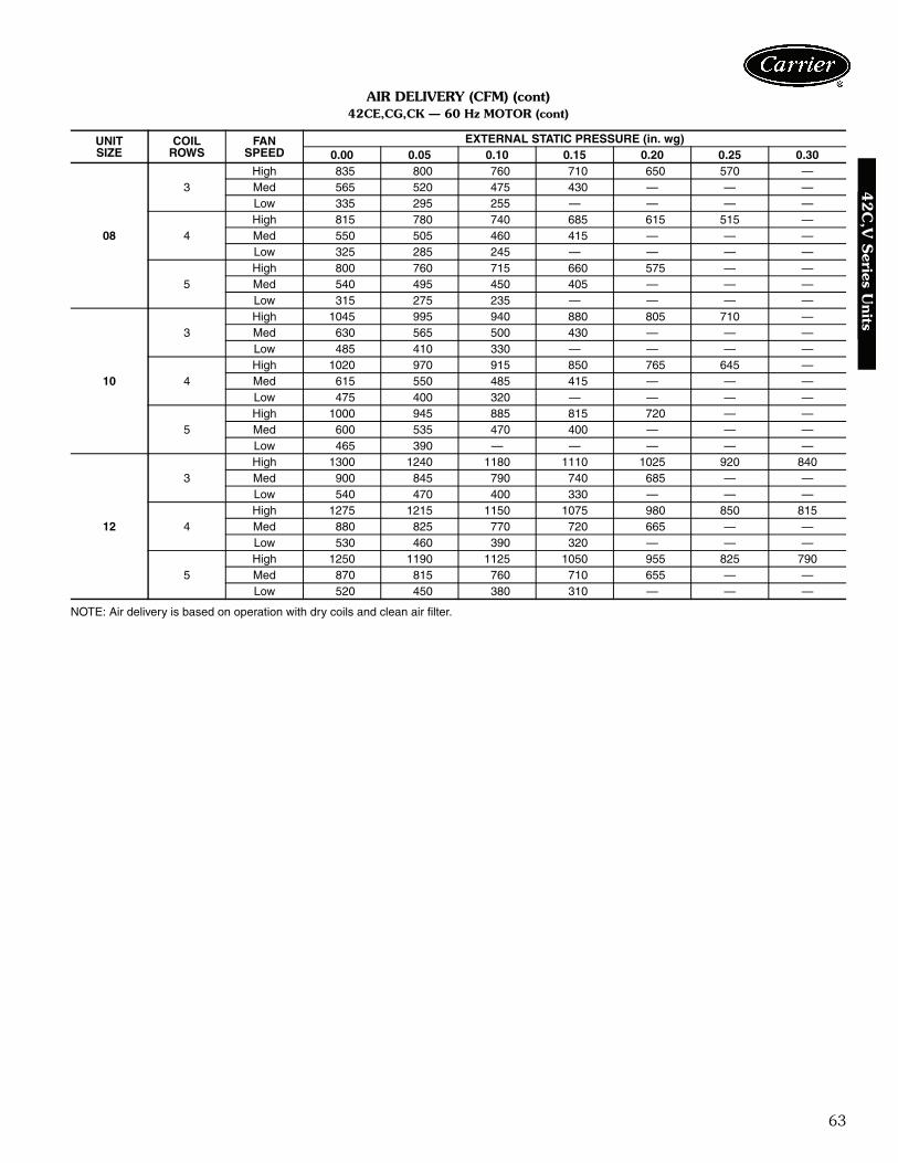
63
AIR DELIVERY (CFM) (cont)42CE,CG,CK — 60 Hz MOTOR (cont)
NOTE: Air delivery is based on operation with dry coils and clean air filter.
UNITSIZE
COILROWS
FANSPEED
EXTERNAL STATIC PRESSURE (in. wg)0.00 0.05 0.10 0.15 0.20 0.25 0.30
08
3High 835 800 760 710 650 570 —Med 565 520 475 430 — — —Low 335 295 255 — — — —
4High 815 780 740 685 615 515 —Med 550 505 460 415 — — —Low 325 285 245 — — — —
5High 800 760 715 660 575 — —Med 540 495 450 405 — — —Low 315 275 235 — — — —
10
3High 1045 995 940 880 805 710 —Med 630 565 500 430 — — —Low 485 410 330 — — — —
4High 1020 970 915 850 765 645 —Med 615 550 485 415 — — —Low 475 400 320 — — — —
5High 1000 945 885 815 720 — —Med 600 535 470 400 — — —Low 465 390 — — — — —
12
3High 1300 1240 1180 1110 1025 920 840Med 900 845 790 740 685 — —Low 540 470 400 330 — — —
4High 1275 1215 1150 1075 980 850 815Med 880 825 770 720 665 — —Low 530 460 390 320 — — —
5High 1250 1190 1125 1050 955 825 790Med 870 815 760 710 655 — —Low 520 450 380 310 — — —
42
C,V
Series U
nits
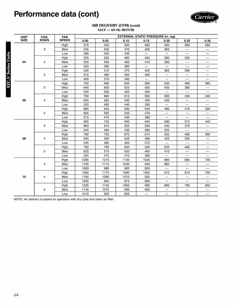
64
AIR DELIVERY (CFM) (cont)42CF — 60 Hz MOTOR
NOTE: Air delivery is based on operation with dry coils and clean air filter.
UNITSIZE
COILROWS
FANSPEED
EXTERNAL STATIC PRESSURE (in. wg)0.00 0.05 0.10 0.15 0.20 0.25 0.30
04
3High 570 540 505 465 420 360 285Med 535 505 470 420 365 — —Low 485 455 430 — — — —
4High 555 520 485 445 390 330 —Med 525 495 460 410 365 — —Low 420 390 360 — — — —
5High 540 510 470 425 365 290 —Med 515 485 450 400 — — —Low 400 370 340 — — — —
06
3High 720 680 635 585 530 460 385Med 640 600 555 505 450 380 —Low 540 500 455 405 — — —
4High 700 660 610 560 500 430 340Med 625 585 540 490 435 — —Low 525 485 440 390 — — —
5High 680 640 590 540 480 410 320Med 605 565 520 470 — — —Low 515 475 430 380 — — —
08
3High 800 750 695 640 580 515 440Med 660 610 555 500 440 375 —Low 545 495 430 385 225 — —
4High 780 725 670 615 555 485 395Med 645 590 535 480 425 350 —Low 535 485 420 375 — — —
5High 760 705 650 595 525 465 —Med 625 575 520 465 410 — —Low 525 475 410 365 — — —
10
3High 1295 1215 1130 1045 960 865 700Med 1195 1115 1030 945 860 — —Low 1060 980 900 820 — — —
4High 1260 1175 1090 1005 915 810 700Med 1165 1095 1010 925 — — —Low 1035 955 875 800 — — —
5High 1235 1150 1065 980 890 790 655Med 1145 1075 990 905 — — —Low 1015 935 855 — — — —
Performance data (cont)4
2C
,V S
erie
s U
nits
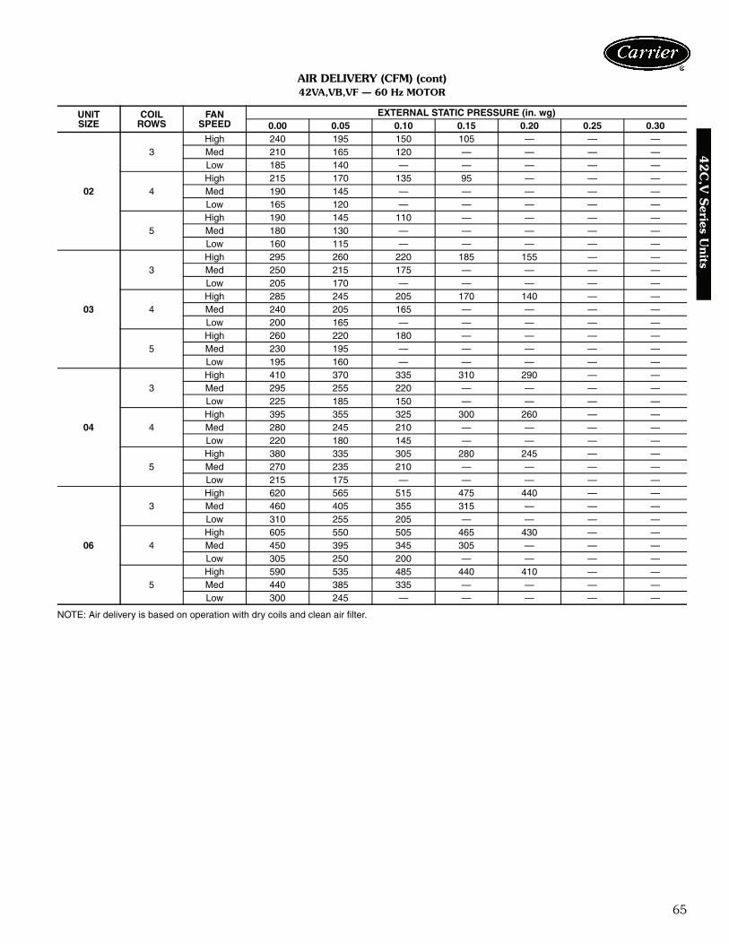
65
AIR DELIVERY (CFM) (cont)42VA,VB,VF — 60 Hz MOTOR
NOTE: Air delivery is based on operation with dry coils and clean air filter.
UNITSIZE
COILROWS
FANSPEED
EXTERNAL STATIC PRESSURE (in. wg)0.00 0.05 0.10 0.15 0.20 0.25 0.30
02
3High 240 195 150 105 — — —Med 210 165 120 — — — —Low 185 140 — — — — —
4High 215 170 135 95 — — —Med 190 145 — — — — —Low 165 120 — — — — —
5High 190 145 110 — — — —Med 180 130 — — — — —Low 160 115 — — — — —
03
3High 295 260 220 185 155 — —Med 250 215 175 — — — —Low 205 170 — — — — —
4High 285 245 205 170 140 — —Med 240 205 165 — — — —Low 200 165 — — — — —
5High 260 220 180 — — — —Med 230 195 — — — — —Low 195 160 — — — — —
04
3High 410 370 335 310 290 — —Med 295 255 220 — — — —Low 225 185 150 — — — —
4High 395 355 325 300 260 — —Med 280 245 210 — — — —Low 220 180 145 — — — —
5High 380 335 305 280 245 — —Med 270 235 210 — — — —Low 215 175 — — — — —
06
3High 620 565 515 475 440 — —Med 460 405 355 315 — — —Low 310 255 205 — — — —
4High 605 550 505 465 430 — —Med 450 395 345 305 — — —Low 305 250 200 — — — —
5High 590 535 485 440 410 — —Med 440 385 335 — — — —Low 300 245 — — — — —
42
C,V
Series U
nits

66
AIR DELIVERY (CFM) (cont)42VA,VB,VF — 60 Hz MOTOR (cont)
NOTE: Air delivery is based on operation with dry coils and clean air filter.
UNITSIZE
COILROWS
FANSPEED
EXTERNAL STATIC PRESSURE (in. wg)0.00 0.05 0.10 0.15 0.20 0.25 0.30
08
3High 700 640 600 545 500 — —Med 575 515 475 420 — — —Low 360 300 260 — — — —
4High 690 630 590 540 490 — —Med 570 510 470 415 — — —Low 350 290 250 — — — —
5High 680 620 580 530 480 — —Med 560 500 460 — — — —Low 340 280 — — — — —
10
3High 915 850 780 725 655 — —Med 675 650 580 530 — — —Low 490 445 395 345 — — —
4High 885 820 755 700 635 — —Med 650 625 555 — — — —Low 475 420 — — — — —
5High 860 790 720 640 560 — —Med 625 600 520 — — — —Low 465 410 — — — — —
12
3High 1100 1025 970 920 865 — —Med 935 860 805 755 700 — —Low 580 525 500 420 — — —
4High 1070 995 945 895 840 — —Med 910 835 780 730 655 — —Low 565 510 485 405 — — —
5High 1040 965 915 865 810 — —Med 890 820 765 715 640 — —Low 545 490 465 385 — — —
Performance data (cont)4
2C
,V S
erie
s U
nits

67
AIR DELIVERY (CFM) (cont)42VC,VE — 60 Hz MOTOR
NOTE: Air delivery is based on operation with dry coils and clean air filter.
UNITSIZE
COILROWS
FANSPEED
EXTERNAL STATIC PRESSURE (in. wg)0.00 0.05 0.10 0.15 0.20 0.25 0.30
02
2High 250 225 190 150 120 — —Med 170 135 100 — — — —Low 125 90 — — — — —
3High 230 210 180 145 115 — —Med 155 120 — — — — —Low 115 — — — — — —
4High 210 175 145 110 — — —Med 140 105 — — — — —Low 110 — — — — — —
03
2High 370 345 305 275 235 — —Med 285 260 220 — — — —Low 195 170 130 — — — —
3High 345 315 285 255 230 — —Med 265 245 205 — — — —Low 185 160 — — — — —
4High 320 290 260 230 — — —Med 250 230 190 — — — —Low 175 150 — — — — —
04
2High 480 440 400 360 320 — —Med 350 310 290 — — — —Low 240 200 150 — — — —
3High 460 420 385 345 310 — —Med 335 295 275 — — — —Low 230 190 140 — — — —
4High 440 400 365 — — — —Med 320 280 260 — — — —Low 220 180 — — — — —
06
2High 750 700 660 600 560 — —Med 575 525 485 425 — — —Low 395 345 305 — — — —
3High 670 625 580 540 495 — —Med 510 460 425 — — — —Low 355 305 265 — — — —
4High 600 555 510 470 — — —Med 450 400 — — — — —Low 315 275 — — — — —
42
C,V
Series U
nits

68
42C,V UNIT COOLING CAPACITY CORRECTION FACTORS
LEGEND
NOTE: Use sensible heat correction factors when calculating heating capacity.
DIRECT EXPANSION (DX) COIL COOLING CAPACITIES (MBtuh)* —MODELS 42CA,CE,CF,CG,CK
LEGEND
*Capacity based on R-22. Ratings at nominal cfm. All DX units to operate at high speed only.
ACTUALAIRFLOW
(Cfm)
UNIT SIZE02 03 04 06 08 10 12
TH SH TH SH TH SH TH SH TH SH TH SH TH SH100 0.62 0.57 — — — — — — — — — — — —125 0.72 0.69 0.54 0.48 0.44 0.39 — — — — — — — —150 0.82 0.80 0.62 0.57 0.51 0.45 — — — — — — — —175 0.92 0.91 0.69 0.65 0.57 0.50 — — — — — — — —200 1.00 1.00 0.76 0.73 0.62 0.57 0.46 0.41 — — — — — —225 1.08 1.08 0.82 0.80 0.67 0.63 0.51 0.45 — — — — — —250 1.16 1.18 0.89 0.87 0.72 0.69 0.55 0.49 — — — — — —275 — — 0.95 0.94 0.77 0.74 0.58 0.53 0.47 0.42 — — — —300 — — 1.00 1.00 0.82 0.80 0.62 0.57 0.51 0.45 0.43 0.38 — —350 — — 1.11 1.12 0.92 0.91 0.69 0.65 0.57 0.50 0.48 0.46 — —400 — — — — 1.00 1.00 0.76 0.73 0.62 0.57 0.53 0.47 0.46 0.41450 — — — — 1.08 1.08 0.82 0.80 0.67 0.63 0.58 0.52 0.51 0.45500 — — — — 1.16 1.18 0.89 0.87 0.72 0.69 0.62 0.57 0.55 0.47550 — — — — — — 0.95 0.94 0.77 0.74 0.66 0.62 0.58 0.53600 — — — — — — 1.00 1.00 0.82 0.80 0.70 0.67 0.62 0.57700 — — — — — — 1.11 1.12 0.92 0.91 0.78 0.76 0.69 0.65800 — — — — — — — — 1.00 1.00 0.86 0.85 0.76 0.73900 — — — — — — — — 1.08 1.08 0.94 0.93 0.82 0.80
1000 — — — — — — — — 1.16 1.18 1.00 1.00 0.89 0.871200 — — — — — — — — — — 1.13 1.14 1.00 1.001400 — — — — — — — — — — — — 1.11 1.12
SH — Sensible HeatTH — Total Heat
UNITSIZE
SST(F)
3 ROW 4 ROWEntering Air (F) — db/wb
76/63 78/65 80/67 82/69 76/63 78/65 80/67 82/69TH SH TH SH TH SH TH SH TH SH TH SH TH SH TH SH
02
35 7.3 5.4 8.1 5.7 9.0 5.9 9.9 6.1 9.0 6.4 10.0 6.7 11.0 7.0 12.1 7.340 5.7 4.7 6.6 4.9 7.4 5.2 8.3 5.4 7.3 5.6 8.3 5.9 9.3 6.2 10.3 6.545 4.3 4.0 4.9 4.2 5.7 4.5 6.6 4.7 5.6 4.8 6.4 5.1 7.4 5.4 8.5 5.750 3.1 3.1 3.6 3.5 4.1 3.8 4.5 4.0 4.1 4.0 4.7 4.3 5.5 4.6 6.4 4.9
03
35 10.5 7.8 11.6 8.1 12.8 8.4 14.0 8.7 12.7 9.1 14.0 9.5 15.3 9.8 16.6 10.240 8.4 6.8 9.5 7.1 10.7 7.5 11.9 7.8 10.5 8.1 11.8 8.5 13.1 8.8 14.5 9.245 6.3 5.8 7.3 6.2 8.5 6.5 9.7 6.8 8.1 7.0 9.3 7.4 10.7 7.8 12.1 8.150 4.7 4.7 5.4 5.2 6.2 5.6 7.2 5.9 6.0 6.0 6.9 6.3 8.1 6.7 9.4 7.1
04
35 14.1 10.4 15.5 10.8 16.9 11.1 18.4 11.5 16.4 11.9 17.9 12.3 19.4 12.7 21.0 13.040 11.6 9.2 13.0 9.6 14.5 10.0 16.0 10.4 13.8 10.7 15.4 11.1 17.0 11.5 18.6 11.945 8.9 8.0 10.2 8.4 11.7 8.9 13.2 9.3 10.9 9.4 12.5 9.8 14.2 10.3 15.8 10.850 6.6 6.6 7.6 7.2 8.8 7.7 10.2 8.1 8.2 8.0 9.4 8.5 11.0 9.0 12.7 9.5
06
35 19.0 14.5 21.0 15.0 23.1 15.6 25.3 16.1 23.3 17.1 25.6 17.7 27.9 18.3 30.3 18.940 15.2 12.7 17.3 13.3 19.4 13.9 21.6 14.5 19.3 15.2 21.6 15.9 24.0 16.6 26.5 17.245 11.6 11.0 13.3 11.6 15.2 12.2 17.4 12.8 15.0 13.3 17.1 14.0 19.6 14.7 22.1 15.350 8.7 8.7 9.9 9.8 11.2 10.5 13.0 11.1 10.9 10.9 12.8 12.0 14.8 12.7 17.1 13.4
08
35 24.6 18.8 27.0 19.4 29.4 20.0 31.9 20.6 29.1 21.8 31.7 22.5 34.3 23.1 37.0 23.640 20.1 16.8 22.6 17.5 25.2 18.2 27.8 18.9 24.6 19.7 27.4 20.5 30.1 21.2 33.0 21.845 15.6 14.7 17.8 15.4 20.3 16.2 23.0 16.9 19.6 17.4 22.2 18.3 25.1 19.1 28.1 19.850 11.9 11.9 13.4 13.2 15.3 14.0 17.6 14.8 14.6 14.6 17.0 15.9 19.5 16.8 22.4 17.6
10
35 29.9 23.3 32.7 24.0 35.6 24.7 38.5 25.3 35.2 26.9 38.3 27.6 41.3 28.2 44.4 28.840 24.7 21.0 27.7 21.8 30.7 22.6 33.8 23.3 30.0 24.5 33.3 25.4 36.6 26.2 39.9 26.945 19.3 18.4 22.0 19.3 24.9 20.2 28.1 21.0 24.1 21.8 27.3 22.8 30.7 23.7 34.3 24.650 14.8 14.8 16.7 16.6 19.0 17.6 21.8 18.6 18.2 18.2 21.1 19.9 24.1 21.0 27.5 22.0
12
35 40.3 30.0 44.4 31.1 48.7 32.2 53.1 33.3 48.2 35.0 52.7 36.2 57.4 37.4 62.2 38.540 32.7 26.4 36.9 27.7 41.2 28.9 45.7 30.0 40.2 31.2 44.9 32.6 49.8 33.9 54.7 35.145 24.9 22.9 28.6 24.1 32.9 25.4 37.4 26.6 31.5 27.2 36.1 28.7 41.0 30.1 46.1 31.450 18.6 18.6 21.2 20.6 24.4 21.9 28.4 23.1 23.5 23.1 26.9 24.7 31.3 26.1 36.3 27.5
db — Dry BulbMBtuh— Btuh in ThousandsSH — Sensible HeatSST — Saturated Suction TemperatureTH — Total Heatwb — Wet Bulb
Performance data (cont)4
2C
,V S
erie
s U
nits

69
DIRECT EXPANSION (DX) COIL COOLING CAPACITIES (MBtuh)* —MODELS 42VA,VB,VF
LEGEND
*Capacity based on R-22. Ratings at nominal cfm. All DX units to oper-ate at high speed only.NOTE: DX coils are not available for 42VC,VE,VG units.
DIRECT EXPANSION (DX) COIL AIRFLOWCORRECTION FACTORS
NOTES:1. Consult factory for values outside of table.2. DX Total Capacity (MBtuh) =
Base TH x Total Correction FactorDX Sensible Capacity (MBtuh) =
Base SH x Sensible Correction Factor% of Nominal cfm =Actual cfm (from Air Delivery tables)
Nominal cfm
UNITSIZE
SST(F)
3 ROW 4 ROWEntering Air (F) — db/wb
76/63 78/65 80/67 82/69 76/63 78/65 80/67 82/69TH SH TH SH TH SH TH SH TH SH TH SH TH SH TH SH
02
35 6.7 4.9 7.4 5.1 8.2 5.3 9.1 5.6 8.2 5.8 9.1 6.0 10.1 6.3 11.1 6.540 5.3 4.2 6.0 4.4 6.8 4.7 7.6 4.9 6.7 5.0 7.5 5.3 8.4 5.5 9.4 5.845 3.9 3.6 4.5 3.8 5.3 4.0 6.1 4.3 5.1 4.3 5.9 4.5 6.8 4.8 7.7 5.150 2.8 2.8 3.3 3.2 3.8 3.4 4.5 3.6 3.7 3.6 4.3 3.8 5.0 4.1 5.9 4.3
03
35 9.7 7.1 10.7 7.4 11.8 7.7 12.9 8.0 11.6 8.2 12.8 8.6 14.0 8.9 15.3 9.240 7.8 6.2 8.8 6.5 9.9 6.8 11.0 7.1 9.6 7.2 10.8 7.6 12.0 8.0 13.3 8.345 5.8 5.3 6.7 5.6 7.8 5.9 8.9 6.2 7.4 6.2 8.5 6.6 9.8 7.0 11.0 7.350 4.2 4.2 4.9 4.7 5.7 5.0 6.7 5.3 5.4 5.3 6.3 5.6 7.4 6.0 8.6 6.3
04
35 13.0 9.5 14.3 9.8 15.7 10.2 17.1 10.5 15.1 10.8 16.5 11.2 18.0 11.5 19.4 11.940 10.7 8.4 12.0 8.8 13.4 9.1 14.8 9.5 12.7 9.6 14.2 10.0 15.7 10.5 17.2 10.845 8.2 7.2 9.5 7.6 10.8 8.0 12.3 8.4 10.0 8.4 11.5 8.8 13.0 9.3 14.6 9.750 6.0 6.0 6.9 6.5 8.1 6.9 9.5 7.3 7.4 7.2 8.6 7.6 10.1 8.1 11.7 8.5
06
35 17.5 13.1 19.5 13.7 21.4 14.2 23.4 14.7 21.4 15.5 23.6 16.1 25.7 16.6 28.0 17.240 14.0 11.5 15.9 12.1 17.9 12.6 20.0 13.2 17.7 13.7 19.9 14.3 22.1 15.0 24.4 15.645 10.6 9.9 12.2 10.5 14.1 11.0 16.1 11.6 13.7 11.9 15.7 12.5 18.0 13.2 20.3 13.850 7.9 7.9 9.0 8.9 10.3 9.4 12.0 10.0 10.1 10.0 11.6 10.7 13.5 11.3 15.7 12.0
08
35 22.8 17.1 25.1 17.7 27.4 18.3 29.8 18.8 27.0 19.8 29.4 20.4 31.9 21.0 34.5 21.640 18.6 15.2 21.0 15.9 23.4 16.5 25.8 17.1 22.7 17.8 25.3 18.5 27.9 19.2 30.6 19.845 14.4 13.2 16.4 13.9 18.8 14.6 21.3 15.3 18.0 15.6 20.5 16.4 23.2 17.2 26.0 17.950 10.7 10.7 12.3 11.9 14.1 12.7 16.3 13.3 13.5 13.3 15.5 14.2 17.9 15.0 20.7 15.8
10
35 28.0 21.3 30.7 22.0 33.4 22.7 36.2 23.3 32.9 24.5 35.8 25.2 38.8 25.9 41.7 26.540 23.0 19.1 25.8 19.9 28.7 20.6 31.7 21.3 27.9 22.2 31.0 23.0 34.2 23.8 37.4 24.545 17.9 16.6 20.4 17.5 23.3 18.3 26.3 19.2 22.3 19.6 25.3 20.5 28.6 21.4 32.0 22.350 13.5 13.5 15.4 15.0 17.6 16.0 20.2 16.8 16.9 16.8 19.3 17.8 22.3 18.8 25.6 19.8
12
35 37.1 27.2 41.0 28.3 45.0 29.3 49.1 30.4 44.2 31.6 48.5 32.8 52.8 33.4 57.3 35.040 30.1 23.9 34.0 25.1 38.0 26.2 42.2 27.3 36.8 28.0 41.2 29.3 45.7 30.6 50.3 31.845 22.9 20.6 26.4 21.8 30.4 22.9 34.5 24.1 28.7 24.3 33.0 25.7 37.6 27.0 42.3 28.350 16.8 16.8 19.4 18.5 22.5 19.7 26.3 20.8 21.2 20.7 24.5 22.0 28.6 23.3 33.3 24.7
db — Dry BulbMBtuh— Btuh in ThousandsSH — Sensible HeatSST — Saturated Suction TemperatureTH — Total Heatwb — Wet Bulb
% OFNOMINALAIRFLOW
(Cfm)
CORRECTION FACTOR
Total Sensible
80 0.95 0.9390 0.97 0.96
100 1.00 1.00110 1.02 1.04120 1.05 1.08
42
C,V
Series U
nits

70
HOT WATER HEATING CAPACITIES (MBtuh)* —MODELS 42CA,CE,CF,CG,CK,VA,VB,VF
NOTE: Ratings based on nominal cfm, 70 F entering dry bulb, 180 F entering wet bulb.
HOT WATER HEATING CAPACITIES (MBtuh) —MODELS 42VC,VE
NOTE: Ratings based on nominal airflow (cfm), 70 F entering dry bulb, 180 F entering wet bulb.
ROWS UNITSIZE
WATER FLOW (GPM)0.5 1.0 1.5 2.0 3.0 4.0 5.0 6.0 7.0 8.0 10.0 12.0
1
02 7.6 8.8 9.2 9.4 9.6 9.8 — — — — — —03 9.3 11.2 12.0 12.5 12.8 13.0 — — — — — —04 12.0 14.0 15.3 16.2 16.8 17.1 — — — — — —06 13.5 18.0 20.4 21.8 24.0 24.4 — — — — — —08 — 21.3 24.8 26.5 28.8 30.0 — — — — — —10 — 24.0 30.5 33.5 36.2 37.5 — — — — — —12 — 26.5 35.8 38.8 42.3 44.0 — — — — — —
2
02 12.1 14.1 15.0 15.7 16.4 16.8 — — — — — —03 16.6 19.4 20.6 21.8 23.0 23.5 — — — — — —04 18.5 23.4 25.5 26.7 28.6 29.4 — — — — — —06 — 29.0 33.0 34.8 37.2 38.8 39.8 40.5 41.1 42.0 — —08 — 32.8 37.7 40.8 45.0 46.9 47.5 49.7 50.6 51.4 — —10 — 40.5 47.5 51.4 56.5 59.5 61.5 63.5 65.0 66.0 — —12 — 49.0 55.5 59.5 64.7 68.0 70.7 72.7 74.0 75.3 — —
3
02 15.0 17.4 18.6 19.4 20.3 20.8 — — — — — —03 20.0 24.0 25.5 26.9 28.5 29.6 — — — — — —04 22.5 29.0 31.6 33.0 35.2 36.4 — — — — — —06 — — 40.5 43.0 46.0 47.8 49.0 50.0 50.6 51.1 — —08 — — 47.0 51.2 55.5 58.0 60.0 61.5 62.6 63.5 — —10 — — — 63.5 69.5 73.5 76.0 78.4 80.0 81.5 82.8 84.512 — — — 70.0 79.4 84.2 87.5 90.0 92.0 93.4 96.0 —
4
02 17.2 20.0 21.2 21.8 22.5 23.0 — — — — — —03 21.5 27.0 29.1 30.0 31.8 32.6 — — — — — —04 25.0 33.0 35.6 37.0 38.5 39.6 — — — — — —06 — — 46.0 50.0 53.5 55.0 56.0 57.0 57.8 58.7 — —08 — — 51.3 55.0 60.0 63.0 65.0 66.4 67.4 68.3 — —10 — — — 70.5 77.7 81.5 84.1 86.3 88.0 89.5 91.3 92.512 — — — 82.5 92.5 97.5 101.1 104.0 106.5 108.5 110.5 112.0
ROWS UNITSIZE
WATER FLOW (GPM)0.5 1.0 1.5 2.0 2.5 3.0 4.0
1
02 7.2 9.7 10.4 10.7 10.8 — —03 9.5 12.4 14.1 15.1 15.5 — —04 10.1 14.5 17.4 19.4 20.8 21.5 22.206 14.6 20.2 23.5 26.0 27.5 28.7 29.7
2
02 11.2 14.3 15.6 16.5 17.2 17.7 —03 14.3 19.1 21.8 23.4 24.3 24.6 —04 — 22.6 27.1 30.0 32.0 33.2 34.106 — 31.1 36.6 39.7 42.0 44.1 46.8
3
02 12.8 16.5 18.4 19.7 20.7 21.4 —03 18.0 22.8 25.9 27.7 28.8 29.4 —04 — 25.5 31.8 33.6 35.2 36.2 36.806 — 37.0 40.9 43.7 46.0 47.8 51.0
Performance data (cont)4
2C
,V S
erie
s U
nits

71
COOLING AND HEATING CAPACITIES (Btuh) — MODEL 42VG
NOTE: Cooling capacity based on standard conditions at 80 F dry bulb,67 F wet bulb entering air temperature. To determine sensible, use ratioof 0.83 to above total.
42C,V UNIT HOT WATER CAPACITY CORRECTION FACTORS
NOTE: Hot Water Capacity (MBtuh) = Base Capacity x Hot WaterCapacity Correction Factor x SH (SH value found in Cooling CapacityCorrection Factors table on page 68).
STEAM HEATING CAPACITIES (Btuh)MODELS 42VA,VB,VF,CA,CE,CF,CG,CK
NOTES:1. Ratings based on nominal cfm, 70 F entering dry bulb, 2 psig.2. All capacities above 50,000 Btuh rating are beyond the capacity of
the standard control valve. Consult factory for these applications.3. Steam coils are not available for 42VC,VE,VG units.
HOT WATER AND CHILLED WATER COIL Cv FACTORS
LEGEND
UNITSIZE
AIRFLOW(Cfm)
WATER FLOW(Gpm)
PRESSUREDROP(ft wg)
COOLING HEATINGEntering Water Temperature (F)
40 45 50 160 180
01 150
1.0 0.8 4,240 3,450 2,750 8,200 10,0001.5 1.6 4,950 4,080 3,270 8,750 10,8502.0 2.7 5,320 4,500 3,500 9,220 11,3002.5 3.6 5,500 4,620 3,620 9,450 11,7003.0 5.5 5,590 4,850 3,770 9,700 12,300
03 300
1.0 1.5 7,850 6,400 5,100 15,500 18,9001.5 2.9 8,850 7,800 6,250 16,700 20,4002.0 4.8 10,200 8,660 6,730 17,300 21,1002.5 6.4 10,800 9,100 7,130 17,600 21,5003.0 9.7 11,100 9,650 7,500 18,000 22,000
ENTERINGAIR TEMP (F)
ENTERING WATER TEMPERATURE (F)100 110 120 130 140 150 160 170 180 190 200
50 0.455 0.545 0.636 0.727 0.818 0.909 1.000 1.091 1.182 1.273 1.36455 0.409 0.500 0.591 0.682 0.773 0.864 0.955 1.045 1.136 1.227 1.31860 0.363 0.455 0.545 0.636 0.727 0.818 0.909 1.000 1.091 1.182 1.27365 0.318 0.409 0.500 0.591 0.682 0.773 0.864 0.955 1.045 1.136 1.22770 0.272 0.363 0.455 0.545 0.636 0.727 0.818 0.909 1.000 1.091 1.18275 0.227 0.318 0.409 0.500 0.591 0.682 0.773 0.864 0.955 1.045 1.13680 0.182 0.272 0.363 0.455 0.545 0.636 0.727 0.818 0.909 1.000 1.091
UNIT SIZE 1-ROW COIL 2-ROW COIL02 12,270 19,92003 16,890 28,58004 21,940 37,53006 31,610 54,99508 40,415 71,25010 52,685 91,65512 62,355 109,120
UNIT SIZE 1-ROW 2-ROW 3-ROW 4-ROW
42CA, 42CE, 42CK, 42CG,42CF, 42VA, 42VB, 42VF
02 2.1 1.4 1.1 1.003 1.9 1.3 1.0 0.904 1.8 1.2 0.9 0.906 1.5 2.8 2.4 2.008 1.4 2.6 2.2 1.910 1.3 2.4 3.3 3.112 1.2 2.2 3.2 3.0
42VC, 42VE
02 1.8 1.2 1.0 —03 1.6 1.1 1.0 —04 1.5 1.0 2.0 —06 1.3 2.3 1.9 —
Cv — Coefficient of Velocity
42
C,V
Series U
nits
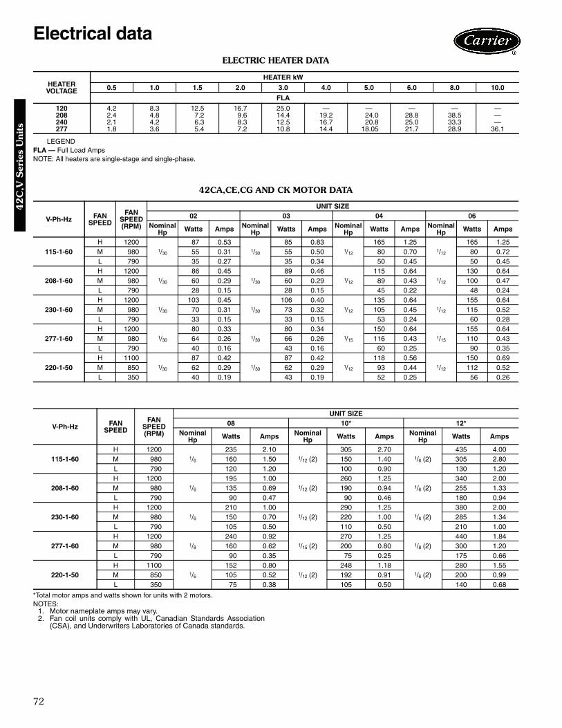
72
ELECTRIC HEATER DATA
LEGENDFLA — Full Load AmpsNOTE: All heaters are single-stage and single-phase.
42CA,CE,CG AND CK MOTOR DATA
*Total motor amps and watts shown for units with 2 motors.NOTES:
1. Motor nameplate amps may vary.2. Fan coil units comply with UL, Canadian Standards Association
(CSA), and Underwriters Laboratories of Canada standards.
HEATERVOLTAGE
HEATER kW
0.5 1.0 1.5 2.0 3.0 4.0 5.0 6.0 8.0 10.0
FLA
120 4.2 8.3 12.5 16.7 25.0 — — — — —208 2.4 4.8 7.2 9.6 14.4 19.2 24.0 28.8 38.5 —240 2.1 4.2 6.3 8.3 12.5 16.7 20.8 25.0 33.3 —277 1.8 3.6 5.4 7.2 10.8 14.4 18.05 21.7 28.9 36.1
V-Ph-Hz FANSPEED
FANSPEED(RPM)
UNIT SIZE02 03 04 06
Nominal Hp Watts Amps Nominal
Hp Watts Amps Nominal Hp Watts Amps Nominal
Hp Watts Amps
115-1-60H 1200
1/30
87 0.531/30
85 0.831/12
165 1.251/12
165 1.25M 980 55 0.31 55 0.50 80 0.70 80 0.72L 790 35 0.27 35 0.34 50 0.45 50 0.45
208-1-60H 1200
1/30
86 0.451/30
89 0.461/12
115 0.641/12
130 0.64M 980 60 0.29 60 0.29 89 0.43 100 0.47L 790 28 0.15 28 0.15 45 0.22 48 0.24
230-1-60H 1200
1/30
103 0.451/30
106 0.401/12
135 0.641/12
155 0.64M 980 70 0.31 73 0.32 105 0.45 115 0.52L 790 33 0.15 33 0.15 53 0.24 60 0.28
277-1-60H 1200
1/30
80 0.331/30
80 0.341/15
150 0.641/15
155 0.64M 980 64 0.26 66 0.26 116 0.43 110 0.43L 790 40 0.16 43 0.16 60 0.25 90 0.35
220-1-50H 1100
1/30
87 0.421/30
87 0.421/12
118 0.561/12
150 0.69M 850 62 0.29 62 0.29 93 0.44 112 0.52L 350 40 0.19 43 0.19 52 0.25 56 0.26
V-Ph-Hz FANSPEED
FANSPEED(RPM)
UNIT SIZE08 10* 12*
Nominal Hp Watts Amps Nominal
Hp Watts Amps NominalHp Watts Amps
115-1-60H 1200
1/6
235 2.101/12 (2)
305 2.701/6 (2)
435 4.00M 980 160 1.50 150 1.40 305 2.80L 790 120 1.20 100 0.90 130 1.20
208-1-60H 1200
1/6
195 1.001/12 (2)
260 1.251/6 (2)
340 2.00M 980 135 0.69 190 0.94 255 1.33L 790 90 0.47 90 0.46 180 0.94
230-1-60H 1200
1/6
210 1.001/12 (2)
290 1.251/6 (2)
380 2.00M 980 150 0.70 220 1.00 285 1.34L 790 105 0.50 110 0.50 210 1.00
277-1-60H 1200
1/8
240 0.921/15 (2)
270 1.251/8 (2)
440 1.84M 980 160 0.62 200 0.80 300 1.20L 790 90 0.35 75 0.25 175 0.66
220-1-50H 1100
1/6
152 0.801/12 (2)
248 1.181/6 (2)
280 1.55M 850 105 0.52 192 0.91 200 0.99L 350 75 0.38 105 0.50 140 0.68
Electrical data4
2C
,V S
erie
s U
nits
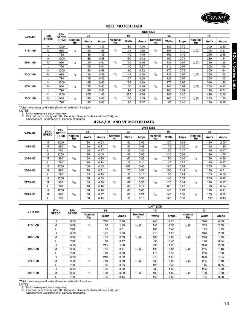
73
42CF MOTOR DATA
*Total motor amps and watts shown for units with 2 motors.NOTES:
1. Motor nameplate amps may vary.2. Fan coil units comply with UL, Canadian Standards Association (CSA), and
Underwriters Laboratories of Canada standards.42VA,VB, AND VF MOTOR DATA
*Total motor amps and watts shown for units with 2 motors.NOTES:
1. Motor nameplate amps may vary.2. Fan coil units comply with UL, Canadian Standards Association (CSA), and
Underwriters Laboratories of Canada standards.
V-Ph-Hz FANSPEED
FANSPEED(RPM)
UNIT SIZE04 06 08 10*
NominalHp Watts Amps Nominal
Hp Watts Amps NominalHp Watts Amps Nominal
Hp Watts Amps
115-1-60H 1200
1/8
150 1.401/8
180 1.701/8
180 1.701/8 (2)
300 2.80M 980 160 1.65 175 1.65 195 1.70 345 3.37L 790 135 1.45 140 1.45 165 1.45 290 2.95
208-1-60H 1200
1/8
135 0.681/8
150 0.721/8
160 0.741/8 (2)
280 1.44M 980 120 0.60 130 0.66 135 0.67 250 1.25L 790 105 0.54 110 0.57 110 0.57 205 1.05
230-1-60H 1200
1/8
150 0.681/8
160 0.721/8
170 0.751/8 (2)
300 1.44M 980 128 0.58 145 0.66 135 0.67 260 1.30L 790 115 0.55 127 0.60 127 0.57 205 1.05
277-1-60H 1200
1/8
145 0.601/8
155 0.601/8
170 0.661/8 (2)
310 1.20M 980 125 0.45 130 0.48 145 0.54 265 0.95L 790 90 0.36 90 0.36 100 0.39 195 0.74
220-1-50H 1200
1/6
205 1.001/6
225 0.361/6
256 1.201/6 (2)
420 2.00M 980 145 0.69 150 1.08 160 0.76 285 1.36L 790 93 0.45 95 0.47 95 0.48 180 0.88
V-Ph-Hz FANSPEED
FANSPEED(RPM)
UNIT SIZE02 03 04 06
NominalHp Watts Amps Nominal
Hp Watts Amps NominalHp Watts Amps Nominal
Hp Watts Amps
115-1-60H 1200
1/30
80 0.531/30
80 0.831/12
130 1.251/6
180 2.00M 980 50 0.31 50 0.48 75 0.70 140 1.30L 790 35 0.27 35 0.33 50 0.47 60 0.57
208-1-60H 1200
1/30
85 0.451/30
85 0.461/12
110 0.641/6
190 1.00M 980 60 0.29 60 0.29 85 0.40 130 0.59L 790 28 0.14 28 0.14 45 0.22 90 0.47
230-1-60H 1200
1/30
100 0.451/30
102 0.461/12
120 0.641/6
205 1.00M 980 70 0.31 70 0.31 100 0.43 150 0.71L 790 33 0.15 33 0.15 53 0.24 105 0.50
277-1-60H 1200
1/30
80 0.331/30
82 0.341/15
140 0.631/6
205 0.92M 980 65 0.26 67 0.26 110 0.44 140 0.57L 790 40 0.16 43 0.17 65 0.25 80 0.34
220-1-50H 1200
1/30
80 0.401/30
85 0.401/12
145 0.701/6
175 0.91M 980 60 0.27 60 0.27 140 0.56 155 0.62L 790 30 0.15 30 0.15 120 0.38 130 0.43
V-Ph-Hz FANSPEED
FANSPEED
UNIT SIZE08 10* 12*
NominalHp Watts Amps Nominal
Hp Watts Amps NominalHp Watts Amps
115-1-60H 1200
1/6
210 2.101/12 (2)
240 2.201/6 (2)
370 4.00M 980 140 1.30 145 1.30 265 2.50L 790 65 0.61 100 0.40 125 1.25
208-1-60H 1200
1/6
195 1.001/12 (2)
210 1.201/6 (2)
340 2.00M 980 135 0.69 160 0.80 220 1.15L 790 90 0.47 90 0.45 170 0.84
230-1-60H 1200
1/6
215 1.001/12 (2)
235 1.201/6 (2)
370 2.00M 980 155 0.71 190 0.85 285 1.40L 790 110 0.50 115 0.50 200 1.00
277-1-60H 1200
1/6
210 0.921/12 (2)
270 1.261/6 (2)
370 1.84M 980 140 0.58 200 0.82 255 1.10L 790 85 0.35 125 0.45 145 0.65
220-1-50H 1200
1/6
185 0.921/12 (2)
230 1.301/6 (2)
265 1.73M 980 160 0.63 190 1.02 190 1.00L 790 135 0.44 155 0.60 135 0.80
42
C,V
Series U
nits

74
42VC,VE MOTOR DATA
*Total motor amps and watts shown for units with 2 motors.NOTES:
1. Motor nameplate amps may vary.2. Fan coil units comply with UL, Canadian Standards Association (CSA),
and Underwriters Laboratories of Canada standards.
42VG MOTOR DATA
*Total motor amps and watts shown for units with 2 motors.NOTES:
1. Motor nameplate amps may vary.2. Fan coil units comply with UL, Canadian Standards Association (CSA),
and Underwriters Laboratories of Canada standards.
V-Ph-Hz FANSPEED
FANSPEED(RPM)
UNIT SIZE02 03 04
NominalHp Watts Amps Nominal
Hp Watts Amps NominalHp Watts Amps
115-1-60H 1200
1/20
68 0.341/12
135 1.351/12
150 1.45M 980 45 0.30 65 0.60 65 0.60L 790 25 0.20 40 0.30 40 0.30
208-1-60H 1200
1/2056 0.46
1/12109 0.56
1/12116 0.60
L 790 35 0.20 55 0.30 58 0.30
230-1-60H 1200
1/2064 0.50
1/12128 0.60
1/12138 0.64
L 790 42 0.22 65 0.28 67 0.30
277-1-60H 1200
1/20
85 0.351/12
135 0.581/12
140 0.58M 980 45 0.12 85 0.33 88 0.34L 790 35 0.07 55 0.22 57 0.22
V-Ph-Hz FANSPEED
FANSPEED
UNIT SIZE06*
NominalHp Watts Amps
115-1-60H 1200
1/12 (2)260 2.70
M 980 125 1.20L 790 85 0.80
208-1-60H 1200
1/12 (2)205 1.00
L 790 103 0.50
230-1-60H 1200
1/12 (2)245 1.10
L 790 120 0.52
277-1-60H 1200
1/12 (2)260 1.16
M 980 155 0.65L 790 100 0.40
V-Ph-Hz FANSPEED
FANSPEED(RPM)
UNIT SIZE01 03*
NominalHp Watts Amps Nominal
Hp Watts Amps
115-1-60H 1200
1/20
120 1.561/20 (2)
235 3.10M 980 75 0.92 145 1.80L 790 145 0.78 120 1.54
Electrical data (cont)4
2C
,V S
erie
s U
nits
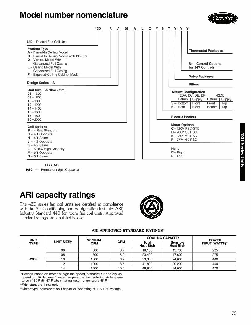
75
ARI capacity ratingsThe 42D series fan coil units are certified in compliancewith the Air Conditioning and Refrigeration Institute (ARI)Industry Standard 440 for room fan coil units. Approvedstandard ratings are tabulated below:
ARI APPROVED STANDARD RATINGS*
*Ratings based on motor at high fan speed, standard air and dry coiloperation, 10 degrees F water temperature rise; entering air tempera-tures of 80 F db, 67 F wb; entering water temperature 45 F.
†With standard 4-row coil.**Motor type, permanent split capacitor, operating at 115-1-60 voltage.
UNITTYPE UNIT SIZE† NOMINAL
CFM GPMCOOLING CAPACITY
POWERINPUT (WATTS)**Total
Heat BtuhSensible
Heat Btuh
42DF
06 600 3.7 18,100 13,700 22508 800 5.0 23,400 17,600 27510 1000 6.9 33,300 24,000 40012 1200 8.7 41,800 30,200 45014 1400 10.0 48,900 34,000 470
Model number nomenclature4
2D
Series U
nits
a42-3995LEGENDPSC — Permanent Split Capacitor
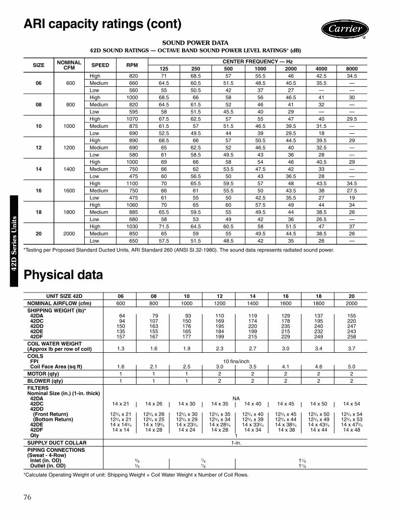
76
SOUND POWER DATA42D SOUND RATINGS — OCTAVE BAND SOUND POWER LEVEL RATINGS* (dB)
*Testing per Proposed Standard Ducted Units, ARI Standard 260 (ANSI SI.32-1980). The sound data represents radiated sound power.
Physical data
*Calculate Operating Weight of unit: Shipping Weight + Coil Water Weight x Number of Coil Rows.
SIZE NOMINALCFM SPEED RPM
CENTER FREQUENCY — Hz125 250 500 1000 2000 4000 8000
06 600High 820 71 68.5 57 55.5 46 42.5 34.5Medium 660 64.5 60.5 51.5 48.5 40.5 35.5 —Low 560 55 50.5 42 37 27 — —
08 800High 1000 68.5 66 58 56 46.5 41 30Medium 820 64.5 61.5 52 46 41 32 —Low 595 58 51.5 45.5 40 29 — —
10 1000High 1070 67.5 62.5 57 55 47 40 29.5Medium 875 61.5 57 51.5 46.5 39.5 31.5 —Low 690 52.5 49.5 44 39 29.5 18 —
12 1200High 890 68.5 66 57 50.5 44.5 39.5 29Medium 690 65 62.5 52 46.5 40 32.5 —Low 580 61 58.5 49.5 43 36 28 —
14 1400High 1000 69 66 58 54 46 40.5 29Medium 750 66 62 53.5 47.5 42 33 —Low 475 60 56.5 50 43 36.5 28 —
16 1600High 1100 70 65.5 59.5 57 48 43.5 34.5Medium 750 66 61 55.5 50 43.5 38 27.5Low 475 61 55 50 42.5 35.5 27 19
18 1800High 1060 70 65 60 57.5 49 44 34Medium 885 65.5 59.5 55 49.5 44 38.5 26Low 680 58 53 49 42 36 26.5 —
20 2000High 1030 71.5 64.5 60.5 58 51.5 47 37Medium 850 65 59 55 49.5 44.5 38.5 26Low 650 57.5 51.5 48.5 42 35 26 —
UNIT SIZE 42D 06 08 10 12 14 16 18 20NOMINAL AIRFLOW (cfm) 600 800 1000 1200 1400 1600 1800 2000SHIPPING WEIGHT (lb)* 42DA 64 79 93 110 119 129 137 155 42DC 94 107 150 169 174 178 195 220 42DD 150 163 176 195 220 235 240 247 42DE 135 155 165 184 199 215 232 243 42DF 157 167 177 199 215 229 249 258COIL WATER WEIGHT(Approx lb per row of coil) 1.3 1.6 1.9 2.3 2.7 3.0 3.4 3.7
COILS FPI 10 fins/inch Coil Face Area (sq ft) 1.6 2.1 2.5 3.0 3.5 4.1 4.6 5.0MOTOR (qty) 1 1 1 2 2 2 2 2BLOWER (qty) 1 1 1 2 2 2 2 2FILTERSNominal Size (in.) (1-in. thick) 42DA NA 42DC 14 x 21 14 x 26 14 x 30 14 x 35 14 x 40 14 x 45 14 x 50 14 x 54 42DD
(Front Return) 123/4 x 21 123/4 x 26 123/4 x 30 123/4 x 35 123/4 x 40 123/4 x 45 123/4 x 50 123/4 x 54(Bottom Return) 123/4 x 21 123/4 x 25 123/4 x 29 123/4 x 34 123/4 x 39 123/4 x 44 123/4 x 49 123/4 x 53
42DE 14 x 143/4 14 x 193/4 14 x 233/4 14 x 283/4 14 x 333/4 14 x 383/4 14 x 433/4 14 x 473/4 42DF 14 x 14 14 x 28 14 x 24 14 x 28 14 x 34 14 x 38 14 x 44 14 x 48 Qty 1SUPPLY DUCT COLLAR 1-in.PIPING CONNECTIONS(Sweat - 4-Row) Inlet (in. OD) 5/8 7/8 11/8 Outlet (in. OD) 5/8 7/8 11/8
ARI capacity ratings (cont)4
2D
Ser
ies
Uni
ts

77
Base unit dimensions4
2D
Series U
nits
42DA FURRED-IN CEILING UNIT WITH ELECTRIC HEAT
*Unit weights are based on dry coils and minimum rows. Weights exclude packaging, valves, and othercomponents.NOTES:
1. Right hand unit shown; left hand unit opposite. Coil connection locations are ± 5/8 inches.2. Sizes 06, 08 and 10 have one motor, one blower; sizes 12 through 20 have 2 motors, 2 blowers.3. Standard 4-row coil shown. Other coil option dimensional data available on request.4. See 42DA-203-1 for optional coil connections.5. Fan switch, wall plate not shown.6. Galvanized finish provided as standard.
UNIT SIZE
NOMAIRFLOW
(Cfm)
DIMENSIONS (in. ± 1/8) QTY/UNIT UNIT WEIGHT*
(lb)A A’ B D’ E H Blower Motor
06 600 23 32 14 131/2 17 181/2 1 1 6408 800 28 37 19 131/2 22 231/2 1 1 7910 1000 32 42 23 141/2 26 271/2 1 1 9012 1200 37 47 28 141/2 31 321/2 2 2 10814 1400 42 52 33 141/2 36 371/2 2 2 11916 1600 47 56 38 131/2 41 421/2 2 2 12418 1800 52 62 43 141/2 46 471/2 2 2 14120 2000 56 66 47 141/2 50 511/2 2 2 151
LEGEND1 — Motor Junction Box2 — Motor-Blower Assembly3 — Electric Strip Heater Element (optional)4 — Auxiliary Drip Lip (Optional, Shipped Loose)5 — Tell-Tale Drain (optional)6 — Drain Connection, 7/8-in. OD7 — Air Vent, 1/8-in. MPT8 — Supply Connection9 — Supply Duct Collar, 1 inch
10 — Return Connection11 — Mounting Holes (four, 3/4-in. diameter) have
Rubber Grommets with 3/8-in. holes.
a42-4120

78
Base unit dimensions (cont)4
2D
Ser
ies
Uni
ts
42DC FURRED-IN CEILING UNIT WITH PLENUM AND ELECTRIC HEAT
*Unit weights are based on dry coils and minimum rows. Weights exclude packaging, valves, and othercomponents.NOTES:
1. Right hand unit shown; left hand unit opposite. Coil connection locations are ± 5/8 inches.2. Sizes 06, 08 and 10 have one motor, one blower. Sizes 12 through 20 have 2 motors, 2 blowers.3. Filter and filter rack are standard.4. Standard 4-row coil shown. Other coil option dimensional data available on request.5. See 42DA-203-1 for optional coil connections.6. Fan switch, wall plate not shown.7. Galvanized finish provided as standard.
UNITSIZE
NOMAIRFLOW
(Cfm)
DIMENSIONS (in. ± 1/8) QTY/UNIT UNIT WEIGHT*
(lb)A A’ B D’ E F G H Blower Motor
06 600 23 32 14 131/2 17 21 251/4 181/2 1 1 9408 800 28 37 19 131/2 22 26 301/4 231/2 1 1 10710 1000 32 42 23 141/2 26 30 341/4 271/2 1 1 15012 1200 37 47 28 141/2 31 35 391/4 321/2 2 2 16914 1400 42 52 33 141/2 36 40 441/4 371/2 2 2 17416 1600 47 56 38 131/2 41 45 491/4 421/2 2 2 17818 1800 52 62 43 141/2 46 50 541/4 471/2 2 2 19520 2000 56 66 47 141/2 50 54 581/4 511/2 2 2 220
LEGEND1 — Motor Junction Box Opposite Piping2 — Insulated Return Air Plenum3 — Mounting Clips (Shipped Loose)4 — Electrical Strip Heater Element (optional)5 — Auxiliary Drip Lip (Shipped Loose) with 3/8-in. Hole6 — Tell-Tale Drain (optional)7 — Drain Connection, 7/8-in. OD8 — Filter Retainer Angle9 — Access Panel
10 — Return Duct Collar, 21/2 inches11 — Air Vent, 1/8-in. MPT12 — Return Connection13 — Filter, 1-in.14 — Supply Duct Collar, 1 inch15 — Supply Connection16 — Mounting Holes (four, 3/4-in. diameter) with
Rubber Grommet
A42-4121
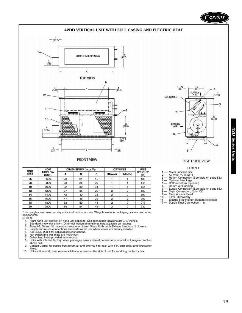
79
42
D S
eries Units
*Unit weights are based on dry coils and minimum rows. Weights exclude packaging, valves, and othercomponents.NOTES:
1. Right hand unit shown; left hand unit opposite. Coil connection locations are ± 5/8 inches.2. Standard 4-row coil shown. Other coil option dimensional data available on request.3. Sizes 06, 08 and 10 have one motor, one blower. Sizes 12 through 20 have 2 motors, 2 blowers.4. Supply and return connections terminate within unit when valves are factory installed.5. See 42DD-203-1 for optional coil connections.6. Fan switch and wall plate are not shown.7. Galvanized finish provided as standard.8. Units with internal factory valve packages have external connections located in triangular section
above coil.9. Consult Carrier for ducted front return air and external filter rack with 1-in. duct collar and throwaway
filters.10. Units with electric heat require additional access on the side of unit for servicing contactor box.
UNITSIZE
NOMAIRFLOW
(Cfm)
DIMENSIONS (in. ± 1/8) QTY/UNIT UNIT WEIGHT*
(lb)A B C Blower Motor
06 600 23 21 15 1 1 13508 800 28 26 20 1 1 14510 1000 32 30 24 1 1 15512 1200 37 35 29 2 2 18014 1400 42 40 34 2 2 19016 1600 47 45 39 2 2 20018 1800 52 50 44 2 2 21520 2000 56 54 48 2 2 230
LEGEND1 — Motor Junction Box2 — Air Vent, 1/8-in. MPT3 — Return Connection (See table on page 83.)4 — Optional 6-in. Legs5 — Bottom Return (optional)6 — Return Air Opening7 — Supply Connection (See table on page 83.)8 — Drain Connection, 7/8-in. OD9 — Front Access Panel
10 — Filter, Throwaway11 — Electric Strip Heater Element (optional)12 — Supply Duct Connection, 1-in.
42DD VERTICAL UNIT WITH FULL CASING AND ELECTRIC HEAT
A42-4122

80
Base unit dimensions (cont)4
2D
Ser
ies
Uni
ts
42DE CEILING UNIT WITH FULL CASING AND ELECTRIC HEAT
*Unit weights are based on dry coils and minimum rows. Weights exclude packaging, valves,and other components.NOTES:
1. Right hand unit shown; left hand unit opposite.2. Coil stub-out location data available on request.3. Unit fabricated of galvanized steel.4. Internal parts fabricated of galvanized steel.5. Sizes 06, 08 and 10 have one motor, one blower. Sizes 12 through 20 have 2 motors,
2 blowers.6. Units must have drain line pitched and trapped externally.7. See 42DA-203-1 for optional coil connections.8. Fan switch, wall plate not shown.9. Galvanized finished provided as standard.
UNIT SIZE
NOM AIRFLOW
(Cfm)
DIMENSIONS (in. ± 1/8) QTY/UNIT UNIT WEIGHT*
(lb)A B C D Blower Motor06 600 31 15 15 26 1 1 15008 800 36 20 20 31 1 1 16010 1000 40 24 24 35 1 1 17012 1200 45 29 29 40 2 2 19514 1400 50 34 34 45 2 2 20516 1600 55 39 39 50 2 2 21518 1800 60 44 44 55 2 2 23020 2000 64 48 48 59 2 2 235
LEGEND1 — Motor Junction Box2 — Unit Mounting Channel (2), 14-gage; 4 Mounting
Slots, 1/2-in. x 2-in.3 — Auxiliary Drip Lip (optional, shipped loose)4 — Side Access Panels5 — Electrical Strip Heater Element (optional)6 — Supply Air Duct Connection, 1 in.7 — Manual Air Vent8 — Filter, Throwaway, 1-in.9 — Return Air Duct Connection, 21/2 in.
10 — Drain, 7/8-in. OD11 — Bottom Access Panel12 — Drain Pan13 — Coil Inlet (See table on page 82.), Copper Sweat
Connection14 — Coil Outlet (See table on page 82.), Copper
Sweat Connection
A42-4123
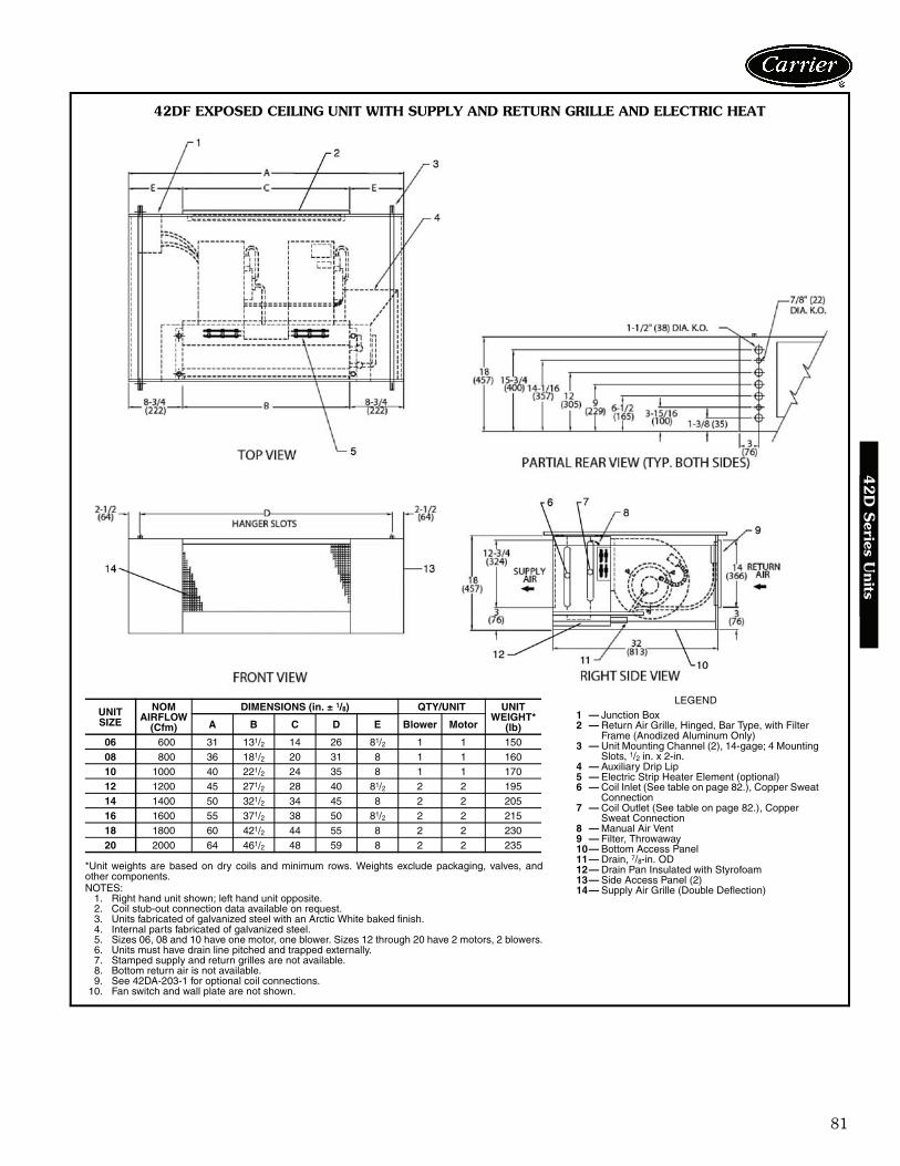
81
42
D S
eries Units
42DF EXPOSED CEILING UNIT WITH SUPPLY AND RETURN GRILLE AND ELECTRIC HEAT
*Unit weights are based on dry coils and minimum rows. Weights exclude packaging, valves, andother components.NOTES:
1. Right hand unit shown; left hand unit opposite.2. Coil stub-out connection data available on request.3. Units fabricated of galvanized steel with an Arctic White baked finish.4. Internal parts fabricated of galvanized steel.5. Sizes 06, 08 and 10 have one motor, one blower. Sizes 12 through 20 have 2 motors, 2 blowers.6. Units must have drain line pitched and trapped externally.7. Stamped supply and return grilles are not available.8. Bottom return air is not available.9. See 42DA-203-1 for optional coil connections.
10. Fan switch and wall plate are not shown.
UNIT SIZE
NOM AIRFLOW
(Cfm)
DIMENSIONS (in. ± 1/8) QTY/UNIT UNIT WEIGHT*
(lb)A B C D E Blower Motor
06 600 31 131/2 14 26 81/2 1 1 15008 800 36 181/2 20 31 8 1 1 16010 1000 40 221/2 24 35 8 1 1 17012 1200 45 271/2 28 40 81/2 2 2 19514 1400 50 321/2 34 45 8 2 2 20516 1600 55 371/2 38 50 81/2 2 2 21518 1800 60 421/2 44 55 8 2 2 23020 2000 64 461/2 48 59 8 2 2 235
LEGEND1 — Junction Box2 — Return Air Grille, Hinged, Bar Type, with Filter
Frame (Anodized Aluminum Only)3 — Unit Mounting Channel (2), 14-gage; 4 Mounting
Slots, 1/2 in. x 2-in.4 — Auxiliary Drip Lip5 — Electric Strip Heater Element (optional)6 — Coil Inlet (See table on page 82.), Copper Sweat
Connection7 — Coil Outlet (See table on page 82.), Copper
Sweat Connection8 — Manual Air Vent9 — Filter, Throwaway10— Bottom Access Panel11— Drain, 7/8-in. OD12— Drain Pan Insulated with Styrofoam13— Side Access Panel (2)14— Supply Air Grille (Double Deflection)
A42-4124
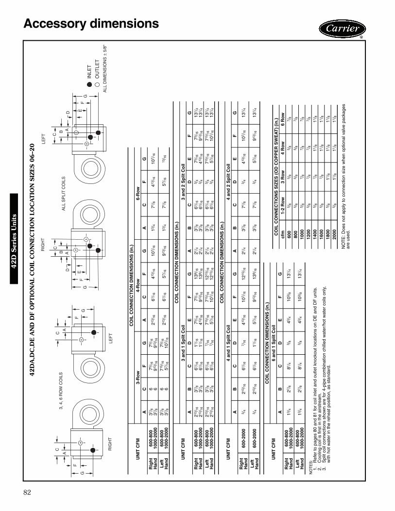
82
Accessory dimensions4
2D
Ser
ies
Uni
ts
42D
A,D
C,D
E A
ND
DF
OPTIO
NA
L C
OIL
CO
NN
EC
TIO
N L
OC
ATIO
N S
IZES 0
6–2
0
a42-3996
NO
TE
S:
1.R
efer
to p
ages
80
and
81 fo
r co
il in
let a
nd o
utle
t kno
ckou
t loc
atio
ns o
n D
E a
nd D
F u
nits
.2.
Coo
ling
coil
is fi
rst i
n th
e ai
rstr
eam
.3.
Spl
it co
il co
nnec
tions
sho
wn
are
for
4-pi
pe c
ombi
natio
n ch
illed
wat
er/h
ot w
ater
coi
ls o
nly,
with
hot
wat
er in
the
rehe
at p
ositi
on, a
s st
anda
rd.
UN
IT C
FM
CO
IL C
ON
NE
CT
ION
DIM
EN
SIO
NS
(in
.)3-
Row
4-R
ow
6-R
owA
CF
GA
CF
GA
CF
GR
igh
t H
and
600-
800
1000
-200
037
/ 837
/ 86 6
75/ 1
691
3 /16
75/ 1
691
3 /16
213 /
1661
/ 16
413 /
1610
7 /16
13/ 4
71/ 8
413 /
1610
7 /16
Lef
t H
and
600-
800
1000
-200
037
/ 837
/ 86 6
715 /
1657
/ 16
75/ 1
610
7 /16
213 /
1661
/ 16
57/ 1
691
3 /16
13/ 4
71/ 8
57/ 1
613
/ 16
UN
IT C
FM
CO
IL C
ON
NE
CT
ION
DIM
EN
SIO
NS
(in
.)3
and
1 S
plit
Co
il3
and
2 S
plit
Co
ilA
BC
DE
FG
AB
CD
EF
GR
igh
t H
and
600-
800
1000
-200
021
3 /16
213 /
16
37/ 8
37/ 8
61/ 1
661
/ 16
11/ 1
611
/ 16
75/ 1
641
3 /16
75/ 1
691
3 /16
139 /
1613
9 /16
21/ 4
21/ 4
37/ 8
37/ 8
61/ 1
661
/ 16
3 /4
3 /4
75/ 1
641
3 /16
75/ 1
691
3 /16
131 /
413
1 /4
Lef
t H
and
600-
800
1000
-200
021
3 /16
213 /
16
37/ 8
37/ 8
61/ 1
661
/ 16
7 /16
7 /16
715 /
1657
/ 16
715 /
1610
7 /16
1215
/ 16
1215
/ 16
21/ 4
21/ 4
37/ 8
37/ 8
61/ 1
661
/ 16
3 /4
3 /4
715 /
1657
/ 16
715 /
1610
7 /16
131 /
413
1 /4
UN
IT C
FM
CO
IL C
ON
NE
CT
ION
DIM
EN
SIO
NS
(in
.)4
and
1 S
plit
Co
il4
and
2 S
plit
Co
ilA
BC
DE
FG
AB
CD
EF
GR
igh
t H
and
600-
2000
3 /4
213 /
1661
/ 16
7 /16
413 /
1610
7 /16
1215
/ 16
21/ 4
37/ 8
71/ 8
3 /4
413 /
1610
7 /16
131 /
4
Lef
t H
and
600-
2000
3 /4
213 /
1661
/ 16
11/ 1
657
/ 16
913 /
1613
9 /16
21/ 4
37/ 8
71/ 8
3 /4
57/ 1
691
3 /16
131 /
4
UN
IT C
FM
CO
IL C
ON
NE
CT
ION
DIM
EN
SIO
NS
(in
.)6
and
1 S
plit
Co
ilA
BC
DE
FG
Rig
ht
Han
d60
0-80
010
00-2
000
13/ 4
27/ 8
81/ 4
3 /8
43/ 4
103 /
813
1 /4
Lef
t H
and
600-
800
1000
-200
013
/ 427
/ 881
/ 43 /
843
/ 410
3 /8
131 /
4
NO
TE
: D
oes
not
appl
y to
con
nect
ion
size
whe
n op
tiona
l val
ve p
acka
ges
are
used
.
CO
IL C
ON
NE
CT
ION
S S
IZE
S (
OD
CO
PP
ER
SW
EA
T)
(in
.)cf
m1-
2 R
ow3
Ro
w4
Ro
w6
Row
600
5 /8
5 /8
5 /8
7 /8
800
5 /8
5 /8
5 /8
7 /8
1000
5 /8
7 /8
7 /8
7 /8
1200
5 /8
7 /8
7 /8
7 /8
1400
5 /8
7 /8
11/ 8
11/ 8
1600
5 /8
7 /8
11/ 8
11/ 8
1800
5 /8
11/ 8
11/ 8
11/ 8
2000
5 /8
11/ 8
11/ 8
11/ 8

83
42
D S
eries Units
42
DD
OPTIO
NA
L C
OIL
CO
NN
EC
TIO
N L
OC
ATIO
N S
IZES 0
6–2
0
a42-3997
NO
TE
: D
oes
not
appl
y to
con
nect
ion
size
whe
n op
tiona
lva
lve
pack
ages
are
use
d.
CO
IL C
ON
NE
CT
ION
S S
IZE
S
(OD
CO
PP
ER
SW
EA
T)
(in
.)
cfm
1-2
Ro
w3
Row
4 R
ow
6 R
ow
600
5 /8
5 /8
5 /8
7 /8
800
5 /8
5 /8
5 /8
7 /8
1000
5 /8
7 /8
7 /8
7 /8
1200
5 /8
7 /8
7 /8
7 /8
1400
5 /8
7 /8
11/ 8
11/ 8
1600
5 /8
7 /8
11/ 8
11/ 8
1800
5 /8
11/ 8
11/ 8
11/ 8
2000
5 /8
11/ 8
11/ 8
11/ 8
NO
TE
S:
1.D
oes
not a
pply
to c
onne
ctio
n si
ze w
hen
optio
nal v
alve
pac
kage
s ar
e us
ed.
2.C
oolin
g co
il is
firs
t in
the
airs
trea
m.
3.S
plit
coil
conn
ectio
ns s
how
n ar
e fo
r 4-
pipe
com
bina
tion
chill
ed w
ater
/hot
wat
er c
oils
onl
y,w
ith h
ot w
ater
in th
e re
heat
pos
ition
, as
stan
dard
.
UN
IT C
FM
CO
IL C
ON
NE
CT
ION
DIM
EN
SIO
NS
(in
.)
3-R
ow
4-R
ow6-
Ro
w
AC
FG
AC
FG
AC
FG
Rig
ht
Han
d60
0-80
010
00-2
000
611 /
1653
/ 881
/ 297
/ 826 23
15/ 1
6
247 /
827
41/ 2
103 /
1623
3 /8
261 /
231
/ 211
1 /8
2315
/ 16
257 /
8
Lef
t H
and
600-
800
1000
-200
07 53
/ 887
/ 810
3 /16
715 /
1657
/ 16
243 /
826
1 /2
43/ 4
97/ 8
2315
/ 16
2515
/ 16
37/ 8
103 /
424
1 /2
253 /
8
UN
IT C
FM
CO
IL C
ON
NE
CT
ION
DIM
EN
SIO
NS
(in
.)
3 an
d 1
Sp
lit C
oil
3 an
d 2
Sp
lit C
oil
AB
CD
EF
GH
AB
CD
EF
GH
Rig
ht
Han
d60
0-80
010
00-2
000
53/ 4
47/ 1
6
51/ 4
51/ 4
75/ 8
815 /
16
127 /
1612
7 /16
1911
/ 16
1911
/ 16
257 /
1623
5 /16
245 /
1626
7 /16
315 /
1631
5 /16
53/ 4
47/ 1
6
59/ 1
659
/ 16
75/ 8
815 /
16
123 /
412
3 /4
201 /
420
1 /4
257 /
1623
5 /16
245 /
1626
1 /16
317 /
831
7 /8
Lef
t H
and
600-
800
1000
-200
061
/ 843
/ 441
5 /16
415 /
16
715 /
1691
/ 412
1 /8
121 /
8
203 /
1620
3 /16
2415
/ 16
2213
/ 16
233 /
425
15/ 1
6
317 /
1631
7 /16
61/ 8
43/ 4
59/ 1
659
/ 16
715 /
1691
/ 412
3 /4
123 /
4
201 /
420
1 /4
2415
/ 16
2213
/ 16
233 /
425
7 /8
317 /
831
7 /8
UN
IT C
FM
CO
IL C
ON
NE
CT
ION
DIM
EN
SIO
NS
(in
.)
4 an
d 1
Sp
lit C
oil
4 an
d 2
Sp
lit C
oil
AB
CD
EF
GH
AB
CD
EF
GH
Rig
ht
Han
d60
0-20
0047
/ 16
513 /
1610
3 /16
131 /
1620
3 /4
233 /
826
7 /16
327 /
1631
/ 259
/ 16
91/ 4
123 /
420
1 /4
2213
/ 16
257 /
831
7 /8
Lef
t H
and
600-
2000
43/ 4
613 /
1697
/ 813
3 /8
201 /
423
7 /8
257 /
831
7 /8
37/ 8
59/ 1
681
5 /16
123 /
420
1 /4
235 /
1625
3 /8
317 /
8

84
42D COOLING CAPACITY (by GPM) 3-ROW COIL
42D COOLING CAPACITY (by GPM) 4-ROW COIL
See Legend on page 85.
UNITSIZE GPM
EAT 75 F DB/63 F WB EAT 80 F DB/67 F WB EAT 85 F DB/71 F WB40 F EWT 45 F EWT 50 F EWT 40 F EWT 45 F EWT 50 F EWT 40 F EWT 45 F EWT 50 F EWT
ΔT TCb SCb ΔT TCb SCb ΔT TCb SCb ΔT TCb SCb ΔT TCb SCb ΔT TCb SCb ΔT TCb SCb ΔT TCb SCb ΔT TCb SCb
06
2 11.8 11.8 10.3 10.0 10.0 9.3 8.1 8.1 8.1 14.1 14.1 11.4 12.1 12.1 10.5 10.2 10.2 9.4 16.5 16.5 12.4 14.4 14.4 11.5 12.3 12.3 10.63 9.3 14.0 11.4 7.7 11.5 10.3 6.2 9.3 8.9 11.3 16.9 12.6 9.5 14.2 11.5 7.8 11.7 10.4 13.3 20.0 13.7 11.5 17.2 12.7 9.6 14.4 11.64 7.7 15.5 12.1 6.2 12.4 10.7 4.9 9.8 9.4 9.4 18.8 13.4 7.8 15.5 12.1 6.2 12.4 10.8 11.2 22.4 14.7 9.5 18.9 13.3 7.8 15.6 12.15 6.5 16.3 12.5 5.2 13.1 11.1 4.1 10.1 9.6 8.0 19.9 13.9 6.6 16.5 12.5 5.2 13.1 11.1 9.5 23.7 15.2 8.1 20.2 13.8 6.6 16.6 12.56 5.7 17.0 12.8 4.5 13.6 11.3 3.5 10.4 9.8 6.9 20.8 14.3 5.7 17.2 12.8 4.5 13.6 11.4 8.3 24.8 15.6 7.0 21.1 14.2 5.8 17.3 12.8
08
2 14.9 14.9 13.2 12.7 12.7 11.8 10.3 10.3 10.3 17.5 17.5 14.6 8.9 26.7 18.6 7.4 22.2 16.7 5.9 17.7 14.9 10.6 31.9 20.4 15.5 15.5 13.64 11.8 17.7 14.8 9.8 14.7 13.3 8.1 12.1 11.5 14.1 21.2 16.3 10.2 25.4 18.1 8.5 21.1 16.3 6.8 17.0 14.6 12.1 30.2 19.7 12.1 18.2 15.06 9.8 19.7 15.7 8.0 16.0 14.0 6.4 12.8 12.2 11.9 23.8 17.4 11.9 23.8 17.4 9.9 19.8 15.7 8.0 16.1 14.1 14.0 28.1 18.9 9.9 19.9 15.88 8.4 20.9 16.3 6.8 16.9 14.5 5.3 13.3 12.7 10.2 25.4 18.1 14.1 21.2 16.3 12.0 18.0 14.9 9.9 14.9 13.4 16.7 25.0 17.7 8.5 21.2 16.3
10 7.3 21.9 16.8 5.9 17.6 14.9 4.6 13.7 13.0 8.9 26.7 18.6 17.5 17.5 14.6 15.2 15.2 13.4 12.9 12.9 12.0 20.4 20.4 15.8 7.4 22.3 16.8
10
2 15.9 15.9 14.7 13.8 13.8 13.0 11.0 11.0 11.0 18.6 18.6 16.3 16.4 16.4 14.9 14.1 14.1 13.2 21.4 21.4 17.8 19.1 19.1 16.6 16.8 16.8 15.24 10.9 21.8 18.3 9.1 18.2 16.5 7.5 15.1 14.3 13.0 26.1 20.1 11.1 22.2 18.5 9.3 18.6 16.7 15.3 30.7 21.8 13.3 26.6 20.3 11.3 22.6 18.76 8.4 25.2 19.9 6.8 20.5 17.8 5.4 16.3 15.5 10.2 30.5 22.0 8.5 25.5 20.0 6.9 20.6 17.9 12.1 36.2 24.0 10.3 30.9 22.0 8.5 25.6 20.08 6.8 27.2 20.8 5.5 21.9 18.5 4.3 17.1 16.1 8.3 33.1 23.1 6.9 27.5 20.8 5.5 21.9 18.6 9.8 39.4 25.2 8.4 33.6 23.0 6.9 27.7 20.8
10 5.7 28.6 21.4 4.6 22.9 18.9 3.5 17.6 16.5 7.0 34.9 23.8 5.8 28.9 21.4 4.6 22.9 19.0 8.3 41.6 26.1 7.1 35.5 23.7 5.8 29.1 21.4
12
2 18.1 18.1 16.6 15.6 15.6 14.6 12.4 12.4 12.4 21.1 21.1 18.6 18.6 18.6 16.9 16.0 16.0 14.9 24.2 24.2 20.4 21.6 21.6 18.9 19.1 19.1 17.24 12.6 25.1 21.3 10.6 21.2 19.2 8.8 17.6 16.6 15.0 29.9 23.5 12.8 25.6 21.6 10.8 21.6 19.5 17.5 35.1 25.5 15.3 30.5 23.7 13.0 26.1 21.96 9.7 29.2 23.4 8.0 23.9 20.9 6.4 19.3 18.2 11.8 35.3 25.8 9.9 29.6 23.5 8.0 24.1 21.1 13.9 41.8 28.1 11.9 35.7 25.8 9.9 29.8 23.68 7.9 31.7 24.5 6.4 25.6 21.8 5.0 20.2 19.0 9.6 38.5 27.2 8.0 32.0 24.5 6.4 25.7 22.0 11.5 45.9 29.7 9.8 39.1 27.1 8.1 32.3 24.6
10 6.7 33.5 25.3 5.4 26.9 22.4 4.2 20.8 19.5 8.2 40.8 28.1 6.8 33.8 25.3 5.4 26.9 22.5 9.7 48.7 30.8 8.3 41.5 28.0 6.8 34.1 25.3
14
4 13.3 26.6 23.4 11.4 22.7 20.9 9.0 17.9 17.9 15.7 31.4 25.8 13.6 27.2 23.7 11.6 23.3 21.3 18.3 36.6 27.9 16.1 32.1 26.1 13.9 27.9 24.16 10.5 31.4 26.0 8.7 26.2 23.4 7.2 21.5 20.3 12.6 37.7 28.6 10.7 32.1 26.3 8.9 26.6 23.7 14.9 44.6 31.1 12.8 38.5 28.9 10.8 32.5 26.58 8.7 34.8 27.6 7.1 28.5 24.7 5.7 22.8 21.5 10.5 42.1 30.5 8.8 35.3 27.7 7.2 28.6 24.9 12.5 50.0 33.2 10.7 42.9 30.6 8.9 35.6 27.8
10 7.4 37.1 28.7 6.0 30.0 25.5 4.7 23.6 22.2 9.0 45.1 31.8 7.5 37.5 28.7 6.0 30.1 25.6 10.8 53.8 34.7 9.2 45.8 31.7 7.6 37.8 28.712 6.5 38.8 29.4 5.2 31.1 26.0 4.0 24.2 22.7 7.9 47.3 32.7 6.5 39.2 29.4 5.2 31.2 26.2 9.4 56.4 35.8 8.0 48.1 32.5 6.6 39.5 29.4
16
4 14.8 29.6 26.1 12.7 25.3 23.3 9.9 19.9 19.9 17.4 34.8 28.8 15.2 30.3 26.4 13.0 26.0 23.7 20.2 40.4 31.2 17.8 35.6 29.2 15.5 31.1 26.96 11.7 35.1 29.2 9.8 29.4 26.3 8.1 24.2 22.8 14.0 41.9 32.2 11.9 35.7 29.5 10.0 29.9 26.7 16.5 49.4 35.0 14.3 42.8 32.5 12.1 36.2 29.88 9.7 38.9 31.1 8.0 32.0 27.9 6.4 25.8 24.3 11.7 46.9 34.4 9.9 39.5 31.3 8.1 32.2 28.1 14.0 55.9 37.5 11.2 44.8 34.5 10.0 39.8 31.4
10 8.3 41.7 32.4 6.7 33.7 28.9 5.3 26.7 25.1 10.1 50.5 35.9 8.4 42.1 32.4 6.8 33.9 29.0 12.0 60.1 39.1 10.2 51.2 35.8 8.5 42.4 32.512 7.3 43.6 33.3 5.9 35.1 29.5 4.6 27.4 25.7 7.2 43.1 36.9 7.3 44.1 33.3 5.9 35.2 29.7 10.5 63.3 40.4 9.0 53.9 36.8 7.4 44.4 33.3
18
4 16.2 32.5 28.7 14.0 27.9 25.6 10.9 21.8 21.8 19.0 38.1 31.7 16.6 33.3 29.1 14.3 28.6 26.0 22.0 44.0 34.4 19.5 39.0 32.1 17.1 34.2 29.66 12.9 38.6 32.4 10.8 32.5 29.2 9.0 26.9 25.2 15.3 46.0 35.7 13.1 39.4 32.8 11.0 33.1 29.5 18.0 54.0 38.7 15.6 46.9 36.0 13.3 39.9 33.18 10.7 42.9 34.6 8.9 35.5 31.1 7.2 28.8 27.0 12.9 51.6 38.1 10.9 43.6 34.8 8.9 35.8 31.4 15.3 61.3 41.6 13.1 52.5 38.3 11.0 43.9 35.0
10 9.2 46.1 36.1 7.5 37.5 32.2 6.0 29.9 28.1 11.2 55.8 39.9 9.3 46.5 36.1 7.5 37.7 32.4 13.2 66.2 43.5 11.3 56.5 39.8 9.4 46.9 36.212 8.1 48.4 37.1 6.5 39.0 33.0 5.1 30.7 28.8 9.8 58.8 41.2 8.1 48.9 37.1 6.5 39.2 33.2 11.7 69.9 45.0 9.9 59.6 41.0 8.2 49.2 37.2
20
4 17.4 34.8 30.9 15.0 29.9 27.4 11.7 23.4 23.4 20.4 40.7 34.2 17.9 35.7 31.3 15.4 30.8 27.9 23.5 47.0 37.1 18.3 36.6 31.7 23.5 47.0 37.16 13.9 41.6 35.2 11.7 35.2 31.7 9.7 29.2 27.2 16.5 49.4 38.8 14.1 42.4 35.6 11.9 35.8 32.0 19.2 57.7 42.0 14.3 43.0 35.9 19.2 57.7 42.08 11.6 46.3 37.7 9.6 38.5 33.9 7.8 31.4 29.4 14.0 55.9 41.7 11.8 47.1 38.0 9.7 38.9 34.2 16.5 65.9 45.3 11.9 47.5 38.2 16.5 65.9 45.3
10 10.0 49.9 39.4 8.1 40.7 35.2 6.5 32.7 30.6 12.0 60.2 43.5 10.1 50.3 39.5 8.2 41.0 35.4 14.3 71.3 47.4 10.1 50.7 39.6 14.3 71.3 47.412 8.7 52.4 40.6 7.1 42.5 36.1 5.6 33.6 31.5 10.6 63.6 45.0 8.8 52.9 40.6 7.1 42.6 36.3 12.6 75.6 49.0 7.2 43.3 40.7 12.6 75.6 49.0
UNITSIZE GPM
EAT 75 F DB/63 F WB EAT 80 F DB/67 F WB EAT 85 F DB/71 F WB40 F EWT 45 F EWT 50 F EWT 40 F EWT 45 F EWT 50 F EWT 40 F EWT 45 F EWT 50 F EWT
ΔT TCb SCb ΔT TCb SCb ΔT TCb SCb ΔT TCb SCb ΔT TCb SCb ΔT TCb SCb ΔT TCb SCb ΔT TCb SCb ΔT TCb SCb
06
4 8.2 16.3 13.1 6.8 13.6 11.8 5.5 11.1 10.4 9.8 19.7 14.4 8.3 16.7 13.2 8.3 16.7 13.2 11.6 23.2 15.7 10.1 20.1 14.5 8.5 17.1 13.46 6.3 18.8 14.2 5.1 15.4 12.7 4.0 12.1 11.1 7.6 22.9 15.8 6.4 19.2 14.3 6.4 19.2 14.3 9.1 27.2 17.3 7.8 23.5 15.8 6.5 19.6 14.48 5.1 20.4 14.9 4.1 16.3 13.1 3.1 12.6 11.4 6.2 24.9 16.6 5.2 20.6 14.9 5.2 20.6 14.9 7.4 29.7 18.3 6.3 25.3 16.5 5.2 20.9 14.8
10 4.2 21.2 15.3 3.4 17.0 13.4 2.6 12.9 11.6 5.2 25.9 17.1 4.3 21.5 15.2 4.3 21.5 15.2 6.2 30.9 18.8 5.3 26.5 17.0 4.4 21.8 15.212 3.6 21.8 15.6 2.9 17.5 13.7 2.2 13.2 11.8 4.4 26.7 17.4 3.7 22.2 15.5 3.7 22.2 15.5 5.3 31.9 19.2 4.6 27.4 17.3 3.8 22.6 15.5
08
4 10.5 20.9 17.0 8.8 17.6 15.4 7.3 14.6 13.5 12.5 25.0 18.7 10.7 21.4 17.2 9.0 18.0 15.7 14.7 29.4 20.3 12.8 25.6 18.9 10.9 21.9 17.46 8.1 24.3 18.6 6.7 20.0 16.7 5.3 16.0 14.7 9.8 29.4 20.6 8.3 24.8 18.7 6.8 20.3 16.8 11.6 34.9 22.5 10.1 30.2 20.6 8.4 25.3 18.88 6.6 26.4 19.6 5.3 21.4 17.3 4.2 16.6 15.1 8.0 32.2 21.8 6.7 26.8 19.5 5.4 21.5 17.4 9.6 38.4 23.9 8.2 32.8 21.6 6.8 27.1 19.5
10 5.5 27.7 20.2 4.5 22.3 17.8 3.4 17.1 15.4 6.8 33.8 22.5 5.6 28.1 20.1 4.5 22.4 17.8 8.1 40.3 24.7 6.9 34.5 22.3 5.7 28.5 20.012 4.8 28.6 20.6 3.8 23.0 18.1 2.9 17.5 15.6 5.8 35.0 23.0 4.9 29.1 20.5 3.9 23.1 18.1 7.0 41.8 25.3 6.0 35.8 22.8 4.9 29.5 20.4
10
4 12.4 24.8 20.6 10.5 21.1 18.6 8.8 17.6 16.3 14.7 29.5 22.6 12.7 25.4 20.8 10.8 21.6 18.9 17.2 34.5 24.4 15.1 30.2 22.8 13.0 26.0 21.16 9.7 29.0 22.6 8.0 24.0 20.3 6.5 19.4 17.9 11.6 34.9 24.9 9.9 29.6 22.7 8.1 24.4 20.5 13.8 41.3 27.1 11.9 35.7 25.0 10.0 30.1 22.88 7.9 31.7 23.8 6.4 25.8 21.2 5.1 20.3 18.6 9.6 38.5 26.4 8.0 32.2 23.8 6.5 26.0 21.3 11.4 45.7 28.9 9.8 39.1 26.3 8.1 32.5 23.8
10 6.7 33.4 24.6 5.4 27.0 21.7 4.2 20.9 19.0 8.1 40.6 27.4 6.8 33.9 24.5 5.4 27.1 21.8 9.7 48.4 30.0 8.3 41.4 27.2 6.9 34.3 24.512 5.8 34.6 25.2 4.6 27.9 22.2 3.6 21.4 19.3 7.0 42.2 28.0 5.9 35.2 25.1 4.7 28.1 22.2 8.4 50.3 30.8 7.2 43.1 27.8 5.9 35.6 25.0
12
4 14.4 28.7 24.0 12.3 24.6 21.8 10.3 20.7 18.9 17.0 33.9 26.4 12.3 24.6 21.8 14.7 29.4 24.3 19.7 39.5 28.5 17.4 34.7 26.6 15.1 30.2 24.76 11.2 33.7 26.5 9.4 28.1 23.9 7.7 23.0 21.1 13.5 40.4 29.2 9.4 28.1 23.9 11.5 34.4 26.9 15.9 47.6 31.8 13.8 41.3 29.3 11.6 34.9 26.98 9.3 37.0 28.1 7.6 30.3 25.1 6.0 24.1 22.0 11.2 44.7 31.1 7.6 30.3 25.1 9.4 37.6 28.1 13.2 53.0 33.9 11.4 45.5 31.0 9.5 37.9 28.1
10 7.8 39.2 29.1 6.4 31.8 25.8 5.0 24.8 22.5 9.5 47.6 32.3 6.4 31.8 25.8 7.9 39.7 29.0 11.3 56.5 35.3 9.7 48.4 32.1 8.0 40.2 29.012 6.8 40.8 29.8 5.5 32.9 26.3 4.2 25.4 22.9 8.3 49.6 33.2 5.5 32.9 26.3 6.9 41.4 29.7 9.9 59.1 36.4 8.4 50.6 33.0 7.0 41.9 29.6
14
3 16.6 24.9 22.5 13.3 19.9 19.9 11.1 16.7 16.7 19.3 29.0 25.2 17.2 25.8 23.0 13.6 20.4 20.4 22.2 33.2 27.5 20.0 30.0 25.7 17.8 26.8 23.57 10.7 37.3 30.0 8.9 31.3 27.1 7.4 25.9 23.8 12.7 44.6 33.0 10.9 38.2 30.3 9.1 32.0 27.5 15.0 52.5 35.8 13.1 45.7 33.3 11.1 39.0 30.7
11 7.9 43.6 33.0 6.5 35.7 29.4 5.1 28.3 25.8 9.6 52.8 36.5 8.1 44.4 33.0 6.6 36.1 29.6 11.4 62.7 39.9 9.8 53.9 36.5 8.2 45.0 33.115 6.3 47.2 34.6 5.1 38.1 30.6 3.9 29.5 26.6 7.7 57.4 38.5 6.4 47.9 34.5 5.1 38.3 30.6 9.1 68.5 42.2 7.8 58.6 38.3 6.5 48.5 34.419 5.2 49.3 35.6 4.2 39.6 31.3 3.2 30.3 27.1 6.3 60.2 39.7 5.3 50.1 35.4 4.2 39.9 31.3 7.6 71.9 43.7 6.5 61.6 39.5 5.4 50.8 35.3
16
3 18.3 27.4 24.8 14.6 21.9 21.9 12.2 18.2 18.2 21.3 32.0 27.8 19.0 28.5 25.4 14.9 22.3 22.3 24.4 36.7 30.5 22.1 33.2 28.4 19.7 29.6 25.97 11.9 41.7 33.8 10.1 35.3 30.6 8.4 29.3 26.9 14.2 49.7 37.2 12.2 42.7 34.2 10.3 36.1 31.1 16.7 58.3 40.3 14.6 50.9 37.5 12.5 43.7 34.6
11 8.9 48.9 37.3 7.3 40.2 33.3 5.9 32.2 29.3 10.8 59.2 41.3 9.1 49.8 37.4 7.4 40.7 33.6 12.8 70.2 45.0 11.0 60.3 41.2 9.2 50.6 37.515 7.1 53.2 39.2 5.7 43.0 34.7 4.5 33.5 30.3 8.6 64.7 43.6 7.2 54.0 39.1 5.8 43.3 34.8 10.3 77.0 47.8 8.8 65.9 43.3 7.3 54.6 39.119 5.9 55.8 40.4 4.7 44.9 35.6 3.6 34.5 30.9 7.2 68.0 45.1 6.0 56.7 40.3 4.8 45.2 35.6 8.5 81.2 49.5 7.3 69.5 44.8 6.0 57.4 40.1
18
3 19.9 29.9 27.0 15.8 23.7 23.7 19.9 29.9 27.0 23.2 34.8 30.2 20.7 31.1 27.6 16.1 24.2 24.2 26.6 39.9 33.3 24.1 36.1 30.9 21.5 32.3 28.27 13.2 46.1 37.6 11.2 39.1 34.0 13.2 46.1 37.6 15.6 54.7 41.2 13.5 47.2 38.0 11.5 40.1 34.5 18.3 63.9 44.7 16.0 56.0 41.6 13.8 48.3 38.4
11 9.9 54.2 41.5 8.1 44.6 37.2 9.9 54.2 41.5 11.9 65.4 45.9 10.0 55.1 41.6 8.2 45.3 37.5 14.1 77.4 50.0 12.1 66.5 45.8 10.2 56.0 41.815 7.9 59.1 43.8 6.4 48.0 38.8 7.9 59.1 43.8 9.6 71.7 48.7 8.0 60.0 43.7 6.4 48.3 38.9 11.4 85.3 53.2 9.7 73.1 48.4 8.1 60.6 43.619 6.5 62.1 45.2 5.3 50.1 39.8 6.5 62.1 45.2 8.0 75.7 50.4 6.6 63.1 45.0 5.3 50.4 39.9 9.5 90.2 55.3 8.1 77.3 50.0 6.7 63.9 44.9
20
3 21.2 31.8 28.7 16.7 25.1 25.1 13.9 20.9 20.9 24.7 37.0 32.3 22.0 33.0 29.4 17.1 25.6 25.6 28.3 42.4 35.5 25.6 38.4 32.9 22.9 34.4 30.07 14.2 49.8 40.9 12.1 42.5 37.1 10.2 35.7 32.4 16.8 58.8 44.9 14.6 51.0 41.4 12.5 43.6 37.6 19.6 68.6 48.6 17.2 60.3 45.3 14.9 52.3 41.9
11 10.7 58.7 45.4 8.8 48.6 40.7 7.2 39.5 35.9 12.8 70.7 50.1 10.8 59.6 45.5 9.0 49.4 41.1 15.2 83.4 54.5 13.0 71.8 50.0 11.0 60.7 45.815 8.6 64.3 48.0 7.0 52.3 42.6 5.5 41.2 37.3 10.4 77.9 53.2 8.7 65.2 47.9 7.0 52.7 42.7 12.3 92.5 58.1 10.6 79.2 52.9 8.8 65.9 47.819 7.1 67.7 49.6 5.8 54.7 43.7 4.5 42.5 38.1 8.7 82.4 55.2 7.2 68.8 79.4 5.8 55.1 43.8 10.3 98.1 60.5 8.8 84.0 54.8 7.3 69.6 49.3
Performance data4
2D
Ser
ies
Uni
ts

85
42D COOLING CAPACITY (by GPM) 6-ROW COIL
LEGEND
NOTE: All capacities are given in thousands of Btuh (MBtuh).
UNITSIZE GPM
EAT 75 F DB/63 F WB EAT 80 F DB/67 F WB EAT 85 F DB/71 F WB40 F EWT 45 F EWT 50 F EWT 40 F EWT 45 F EWT 50 F EWT 40 F EWT 45 F EWT 50 F EWT
ΔT TCb SCb ΔT TCb SCb ΔT TCb SCb ΔT TCb SCb ΔT TCb SCb ΔT TCb SCb ΔT TCb SCb ΔT TCb SCb ΔT TCb SCb
06
4 10.5 15.7 20.9 8.7 14.1 17.3 7.0 12.5 14.0 12.6 17.4 25.2 10.7 15.7 21.4 8.8 14.2 17.7 15.0 18.9 29.9 12.9 17.3 25.9 10.9 15.8 21.96 7.9 17.0 23.7 6.5 15.0 19.4 5.1 13.2 15.2 9.6 19.0 28.9 8.1 17.0 24.3 6.6 15.1 19.7 11.5 20.8 34.5 9.9 18.9 29.8 8.3 17.0 24.98 6.4 17.8 25.4 5.1 15.5 20.5 3.9 13.4 15.7 7.8 19.9 31.1 6.5 17.7 25.9 5.2 15.5 20.7 9.3 22.0 37.1 7.9 19.7 31.8 6.6 17.6 26.3
10 5.3 18.2 26.3 4.2 15.8 21.2 3.2 13.6 16.1 6.4 20.4 32.1 5.4 18.1 26.9 4.3 15.8 21.4 7.7 22.6 38.4 6.6 20.2 33.0 5.5 18.0 27.412 4.5 18.5 26.9 3.6 16.1 21.7 2.7 13.8 16.4 5.5 20.8 32.9 4.6 18.4 27.6 3.7 16.0 22.0 6.6 23.0 39.4 5.7 20.6 34.0 4.7 18.3 28.2
08
4 13.3 20.3 26.6 11.2 18.4 22.3 9.2 16.4 18.5 15.9 22.4 31.9 13.6 20.4 27.3 11.4 18.6 22.8 18.9 24.4 37.7 16.4 22.4 32.7 13.9 20.6 27.96 10.2 22.2 30.5 8.4 19.7 25.1 6.7 17.4 20.0 12.4 24.7 37.1 10.4 22.1 31.2 8.5 19.8 25.5 14.7 27.0 44.2 12.7 24.6 38.1 10.6 22.1 31.98 8.3 23.3 33.0 6.7 20.4 26.7 5.2 17.8 20.7 10.1 26.0 40.2 8.4 23.1 33.6 6.7 20.4 26.9 12.0 28.6 47.9 10.3 25.7 41.1 8.5 23.0 34.1
10 6.9 23.9 34.4 5.5 20.9 27.7 4.3 18.1 21.3 8.4 26.8 41.9 7.0 23.8 35.1 5.6 20.8 28.0 10.0 29.5 50.0 8.6 26.5 43.0 7.1 23.6 35.712 5.9 24.4 35.3 4.7 21.2 28.5 3.6 18.2 21.7 7.2 27.4 43.1 6.0 24.2 36.2 4.8 21.2 28.8 8.6 30.2 51.5 7.4 27.1 44.4 6.1 24.1 36.9
10
4 15.7 31.5 24.5 13.3 26.6 22.2 9.9 19.9 19.9 18.7 37.5 26.9 16.1 32.2 24.7 13.6 27.2 22.5 22.0 44.0 29.2 19.2 38.4 27.0 16.5 32.9 24.96 12.1 36.4 26.8 10.0 30.1 24.0 8.1 24.3 21.3 14.7 44.1 29.8 12.4 37.2 26.8 10.2 30.6 24.1 17.4 52.3 32.5 15.1 45.2 29.7 12.6 37.8 26.98 9.9 39.6 28.3 8.0 32.2 24.9 6.3 25.3 21.8 12.0 48.1 31.6 10.1 40.3 28.2 8.1 32.5 25.0 14.3 57.2 34.6 12.3 49.2 31.2 10.2 40.8 28.0
10 8.3 41.5 29.2 6.7 33.6 25.6 5.2 26.0 22.3 10.1 50.6 32.6 8.5 42.3 29.0 6.8 33.9 25.6 12.0 60.2 35.9 10.4 51.8 32.3 8.6 43.0 28.912 7.2 42.9 29.9 5.8 34.6 26.1 4.4 26.5 22.5 8.7 52.3 33.4 7.3 43.8 29.7 5.8 35.0 26.0 10.4 62.4 36.8 8.9 53.7 33.1 7.4 44.6 29.5
12
4 18.1 36.2 28.6 15.5 30.9 26.1 11.5 23.1 23.1 21.4 42.8 31.3 18.5 37.0 28.9 15.9 31.8 26.5 21.4 42.8 31.3 18.5 37.0 28.9 15.9 31.8 26.56 14.1 42.2 31.5 11.7 35.1 28.3 9.6 28.9 25.3 17.0 50.9 34.8 14.4 43.1 31.6 11.9 35.8 28.5 17.0 50.9 34.8 14.4 43.1 31.6 11.9 35.8 28.58 11.6 46.2 33.4 9.4 37.8 29.5 7.5 30.1 26.1 14.0 56.1 37.1 11.7 46.9 33.2 9.6 38.2 29.6 14.0 56.1 37.1 11.7 46.9 33.2 9.6 38.2 29.6
10 9.8 48.8 34.6 7.9 39.5 30.3 6.2 30.9 26.5 11.9 59.3 38.5 9.9 49.6 34.3 8.0 39.9 30.4 11.9 59.3 38.5 9.9 49.6 34.3 8.0 39.9 30.412 8.4 50.6 35.4 6.8 40.8 30.9 5.3 31.6 26.9 10.3 61.6 39.6 8.6 51.5 35.2 6.9 41.2 30.9 10.3 61.6 39.6 8.6 51.5 35.2 6.9 41.2 30.9
14
3 21.4 32.1 28.0 16.6 25.0 25.0 13.9 20.9 20.9 25.0 37.5 30.8 22.3 33.4 28.6 16.9 25.4 25.4 28.7 43.1 33.4 25.9 38.9 31.4 23.2 34.7 29.17 13.6 47.5 35.9 11.4 39.9 32.5 9.5 33.2 29.1 16.3 56.9 39.6 13.9 48.7 36.1 11.7 40.8 32.8 19.2 67.3 43.1 16.7 58.4 39.6 14.2 49.8 36.4
11 10.0 54.9 39.4 8.2 44.9 34.9 6.5 35.6 30.7 12.1 66.7 43.9 10.2 55.9 39.2 8.3 45.5 35.0 14.4 79.5 48.1 12.4 68.2 43.5 10.3 56.9 39.115 7.9 58.9 41.3 6.3 47.6 36.1 4.9 36.9 31.4 9.6 71.7 46.1 8.0 60.1 41.0 6.4 48.1 36.1 11.4 85.4 50.7 9.8 73.6 45.7 8.1 61.1 40.819 6.4 61.2 42.4 5.2 49.3 36.9 4.0 37.7 31.8 7.9 74.6 47.5 6.6 62.6 42.1 5.3 49.9 36.8 9.4 89.1 52.4 8.1 76.8 47.0 6.7 63.8 41.8
16
3 23.3 35.0 30.7 18.1 27.2 27.2 15.1 22.7 22.7 27.4 41.1 34.3 24.3 36.5 31.3 18.4 27.6 27.6 31.4 47.1 37.0 28.3 42.5 34.8 25.4 38.1 31.97 15.1 53.0 40.4 12.8 44.8 36.6 10.7 37.6 32.8 18.1 63.3 44.5 15.5 54.3 40.7 13.1 45.9 37.1 21.3 74.6 48.4 18.5 64.9 44.5 15.9 55.6 41.0
11 11.2 61.6 44.5 9.2 50.5 39.5 7.4 40.5 34.9 13.6 74.7 49.5 11.4 62.6 44.3 9.3 51.4 39.6 16.1 88.7 54.1 13.9 76.2 49.0 11.6 63.9 42.215 8.9 66.4 46.8 7.2 53.8 41.0 5.6 42.0 35.7 10.8 80.8 52.2 9.0 67.7 46.4 7.2 54.4 40.9 12.8 96.2 57.3 11.0 82.8 51.7 9.2 68.7 46.219 7.3 69.3 48.1 5.9 55.8 41.9 4.5 43.0 36.3 8.9 84.4 53.9 7.4 70.7 47.8 5.9 56.5 41.8 10.6 100.7 59.3 9.1 86.7 53.3 7.6 72.0 47.4
18
5 20.2 50.5 40.9 17.5 43.9 37.4 12.9 32.2 32.2 23.7 59.3 44.7 20.8 52.1 41.5 18.3 45.6 38.2 20.2 50.5 40.9 17.5 43.9 37.4 12.9 32.2 32.29 14.2 63.8 47.5 11.9 53.3 42.7 9.8 44.2 38.3 17.1 76.8 52.5 14.5 65.3 47.6 12.1 54.4 43.0 14.2 63.8 47.5 11.9 53.3 42.7 9.8 44.2 38.3
13 11.0 71.5 51.1 9.0 58.3 45.1 7.1 46.3 39.7 13.3 86.6 56.8 11.2 72.6 50.7 9.1 59.0 45.1 11.0 71.5 51.1 9.0 58.3 45.1 7.1 46.3 39.717 8.9 75.6 53.0 7.2 61.2 46.4 5.6 47.7 40.4 10.8 92.0 59.2 9.1 77.1 52.6 7.3 61.9 46.3 8.9 75.6 53.0 7.2 61.2 46.4 5.6 47.7 40.421 7.5 78.4 54.4 6.0 63.2 47.4 4.6 48.6 41.0 9.1 95.5 60.9 7.6 80.1 54.0 6.1 64.0 47.2 7.5 78.4 54.4 6.0 63.2 47.4 4.6 48.6 41.0
20
5 21.7 54.2 44.4 18.9 47.2 40.5 13.8 34.6 34.6 25.4 63.4 48.6 22.4 55.9 45.1 19.7 49.1 41.2 29.3 73.3 52.4 26.1 65.3 49.1 23.2 57.9 45.99 15.3 69.0 51.8 12.9 58.0 46.8 10.8 48.4 41.9 18.4 82.7 57.2 15.7 70.6 52.0 13.1 59.2 47.1 21.7 97.7 62.2 18.8 84.5 56.9 15.9 71.8 52.1
13 11.9 77.7 55.9 9.8 63.6 49.5 7.8 50.9 43.7 14.5 94.0 62.1 12.1 78.8 55.6 9.9 64.4 49.5 17.1 111.4 67.9 14.7 95.8 61.5 12.3 79.9 55.317 9.7 82.5 58.2 7.9 66.9 51.0 6.2 52.4 44.5 11.8 100.2 64.9 9.9 84.0 57.8 7.9 67.6 51.0 14.0 119.2 71.2 12.1 102.6 64.2 10.0 85.2 57.421 8.2 85.7 59.7 6.6 69.2 52.1 5.1 53.5 45.2 9.9 104.4 66.8 8.3 87.5 59.3 6.7 70.0 52.0 11.8 124.4 73.5 10.2 107.1 66.1 8.5 89.0 58.9
ΔT — Temperature Change GPM — Gallons Per MinuteDB — Dry Bulb SCb — Base Sensible CapacityEAT — Entering Air Temperature TCb — Base Total CapacityEWT — Entering Water Temperature WB — Wet Bulb
42
D S
eries Units

86
42D COOLING CAPACITY (by ΔT) 3-ROW COIL
See Legend on page 87.
42D COOLING CAPACITY (by ΔT) 4-ROW COIL
See Legend on page 87.
UNITSIZE ΔT
EAT 75 F DB/63 F WB EAT 80 F DB/67 F WB EAT 85 F DB/71 F WB40 F EWT 45 F EWT 50 F EWT 40°F EWT 45 F EWT 50 F EWT 40 F EWT 45 F EWT 50 F EWT
GPM TCb SCb GPM TCb SCb GPM TCb SCb GPM TCb SCb GPM TCb SCb GPM TCb SCb GPM TCb SCb GPM TCb SCb GPM TCb SCb
06
4 — — — 7.0 14.0 11.5 5.1 10.2 9.7 — — — — — — 7.0 14.0 11.5 — — — — — — — — —6 5.6 16.7 12.7 4.2 12.5 10.8 3.2 9.4 9.0 7.2 21.6 14.6 5.7 17.0 12.7 4.2 12.6 10.9 — — — 7.3 22.1 14.6 5.7 17.1 12.78 3.8 15.2 12.0 2.8 11.3 10.1 2.0 8.2 8.1 5.0 19.8 13.9 3.9 15.3 12.0 2.9 11.5 10.3 — — — 5.1 20.3 13.8 3.9 15.5 12.1
10 2.7 13.4 11.1 2.0 10.0 9.3 1.4 7.0 7.0 3.7 18.2 13.2 2.8 13.8 11.3 — — — 4.7 23.3 15.0 3.7 18.5 13.2 2.8 14.1 11.512 2.0 11.7 10.3 1.5 8.8 8.3 — — — 2.7 16.1 12.3 — — — — — — 3.6 21.5 14.3 2.8 16.7 12.5 — — —
08
4 — — — — — — 7.0 14.0 13.2 — — — — — — — — — — — — — — — — — —6 7.6 23.2 17.3 5.9 17.5 14.8 4.4 13.0 12.4 — — — — — — 5.9 17.6 14.9 — — — — — — — — —8 5.4 21.3 16.5 4.0 16.0 14.0 3.0 12.1 11.6 6.9 27.7 19.0 5.4 21.6 16.5 4.0 16.1 14.1 — — — 7.1 28.3 19.0 5.5 21.8 16.5
10 3.9 19.5 15.6 2.9 14.6 13.2 2.1 10.6 10.4 5.1 25.6 18.1 3.9 19.7 15.7 3.0 14.9 13.4 6.5 32.6 20.6 5.2 26.1 18.1 4.0 19.8 15.812 2.9 17.5 14.7 2.2 13.2 12.2 — — — 3.9 23.6 17.3 3.0 18.0 14.9 2.3 13.6 12.5 5.0 30.3 19.8 4.0 23.9 17.3 3.0 18.2 15.1
10
4 — — — 11.7 23.5 19.2 8.7 17.3 16.3 — — — — — — 11.7 23.6 19.3 — — — — — — — — —6 9.5 28.2 21.2 7.2 21.3 18.2 5.5 16.0 15.2 11.9 36.2 24.4 9.6 28.6 21.2 7.3 21.4 18.3 — — — — — — 9.7 28.9 21.38 6.5 25.7 20.1 5.0 19.4 17.1 3.6 14.4 13.9 8.4 33.5 23.2 6.6 26.1 20.2 5.1 19.6 17.4 10.5 42.0 26.3 8.6 34.2 23.2 6.7 26.3 20.3
10 4.7 23.0 18.9 3.5 17.4 15.9 2.4 12.1 12.1 6.2 30.8 22.1 4.8 23.6 19.1 3.6 17.9 16.3 7.9 39.2 25.1 6.3 31.3 22.1 4.9 24.0 19.312 3.4 20.4 17.6 2.6 15.5 14.5 1.7 9.9 9.9 4.7 27.7 20.8 3.6 21.1 17.9 2.7 16.2 14.9 5.4 36.3 24.1 4.6 28.5 21.1 3.7 21.8 18.3
12
6 11.4 34.5 25.8 8.8 26.1 22.1 6.6 19.5 18.5 — — — 11.6 35.0 25.8 8.8 26.2 22.2 — — — — — — 11.7 35.4 25.88 7.9 31.6 24.5 6.0 23.9 20.9 4.7 18.1 17.1 10.3 41.1 28.2 8.0 32.1 24.6 6.0 24.1 21.1 — — — 10.5 42.0 28.2 8.1 32.4 24.6
10 5.8 28.9 23.2 4.3 21.8 19.7 3.0 15.2 15.2 7.7 38.0 26.9 5.9 29.4 23.4 4.6 22.3 19.9 9.6 48.2 30.6 7.8 38.7 27.0 5.9 29.7 23.512 4.2 25.8 21.7 3.3 19.8 18.2 2.2 12.9 12.9 5.8 34.9 25.6 4.3 26.6 22.2 3.5 20.4 18.6 7.6 45.0 29.3 5.9 35.6 25.8 4.4 27.3 22.614 3.3 23.3 20.4 2.5 17.6 16.4 — — — 4.4 31.4 24.2 3.4 24.1 20.9 2.6 18.4 17.0 6.0 41.7 28.1 4.5 32.4 24.6 3.5 24.9 21.4
14
6 13.3 39.6 29.7 10.0 29.9 25.5 7.4 22.5 21.3 — — — 13.4 40.2 29.8 10.0 30.1 25.6 — — — — — — 13.6 40.6 29.88 9.1 36.1 28.2 6.9 27.2 24.0 5.2 20.6 19.5 11.8 47.1 32.6 9.3 36.7 28.3 7.0 27.7 24.3 14.7 59.2 36.9 12.0 48.1 32.5 9.3 37.1 28.4
10 6.5 32.3 26.4 4.9 24.5 22.3 3.3 16.4 16.4 8.7 43.2 31.0 6.7 33.3 26.8 5.0 25.3 22.8 11.1 55.2 35.3 8.9 44.2 31.1 6.9 33.8 27.112 4.8 28.7 24.6 3.7 21.8 20.2 2.1 12.7 12.7 6.6 39.0 29.2 5.0 29.8 25.1 3.8 22.8 20.9 8.6 51.0 33.6 6.8 40.3 29.5 5.1 30.8 25.714 3.7 25.4 22.6 2.5 17.4 16.7 — — — 5.0 34.8 27.4 3.8 26.6 23.3 2.8 19.3 18.1 6.7 46.5 31.9 5.2 36.2 27.9 4.0 27.8 24.1
16
6 15.1 46.0 34.3 11.7 34.9 29.4 8.8 26.2 24.6 — — — — — — 11.7 35.0 29.6 — — — — — — — — —10 7.7 38.4 30.9 5.8 29.1 26.1 4.0 19.8 19.8 10.1 50.8 36.0 7.9 39.3 31.2 6.0 29.8 26.6 13.0 64.5 40.9 10.4 51.8 36.0 8.0 39.7 31.414 4.4 30.9 26.9 3.3 23.2 21.5 — — — 6.0 41.9 32.2 4.6 32.2 27.6 3.5 24.5 22.4 8.0 55.8 37.5 6.2 43.4 32.7 4.8 33.4 28.318 2.6 23.3 21.4 — — — — — — 3.8 33.6 28.1 2.8 25.3 22.8 — — — 5.1 45.5 33.4 3.9 35.3 29.0 3.0 27.2 24.122 — — — — — — — — — — — — — — — — — — 3.3 36.4 29.2 2.6 27.6 24.2 — — —
18
6 — — — 13.4 39.9 33.4 9.9 29.9 28.0 — — — — — — 13.4 40.1 33.6 — — — — — — — — —10 9.0 44.5 35.3 6.6 33.7 30.0 4.7 23.2 23.2 11.7 58.3 41.0 9.1 45.3 35.6 7.0 34.4 30.4 14.7 73.8 46.5 11.9 59.4 40.9 9.2 45.7 35.814 5.2 36.5 31.3 4.0 27.8 25.5 — — — 7.1 49.1 37.0 5.4 37.8 31.9 4.1 29.1 26.4 9.3 64.4 42.8 7.3 50.6 37.5 5.6 38.9 32.518 3.2 28.9 26.0 — — — — — — 4.5 40.2 32.9 3.4 31.5 28.0 — — — 6.0 53.9 38.7 4.7 41.9 33.6 3.7 32.6 28.422 — — — — — — — — — 2.9 31.8 27.8 — — — — — — 4.0 44.1 34.4 3.1 34.3 29.3 — — —
20
6 — — — 14.7 44.3 37.1 11.1 33.2 31.1 — — — — — — 14.7 44.5 37.3 — — — — — — — — —10 10.0 49.8 39.3 7.6 37.9 33.5 5.5 27.5 26.5 13.1 65.0 45.5 10.1 50.5 39.5 7.7 38.5 33.9 — — — 13.3 66.3 45.5 10.2 51.0 39.714 5.9 41.3 35.0 4.5 31.6 28.8 2.5 17.5 17.5 8.0 55.8 41.6 6.1 42.7 35.7 4.7 32.9 29.7 10.2 71.9 47.6 8.1 56.8 41.8 6.3 43.6 36.218 3.8 33.6 30.0 2.0 18.0 18.0 — — — 5.1 45.7 37.0 3.9 35.4 31.1 2.4 21.9 20.9 6.9 61.4 43.5 5.3 47.7 37.8 4.1 37.1 32.122 — — — — — — — — — 3.4 37.0 31.8 — — — — — — 4.6 50.6 38.9 3.6 39.3 33.1 2.0 21.9 21.9
UNITSIZE ΔT
EAT 75 F DB/63 F WB EAT 80 F DB/67 F WB EAT 85 F DB/71 F WB40 F EWT 45 F EWT 50 F EWT 40 F EWT 45 F EWT 50 F EWT 40 F EWT 45 F EWT 50 F EWT
GPM TCb SCb GPM TCb SCb GPM TCb SCb GPM TCb SCb GPM TCb SCb GPM TCb SCb GPM TCb SCb GPM TCb SCb GPM TCb SCb
06
4 10.8 21.4 15.4 8.2 16.4 13.2 6.1 12.1 11.2 13.6 27.2 17.7 11.0 21.9 15.4 8.3 16.5 13.2 — — — 14.0 28.0 17.6 11.2 22.3 15.46 6.5 19.2 14.4 4.8 14.4 12.2 3.6 10.8 10.1 8.4 25.1 16.7 6.7 19.7 14.5 4.9 14.8 12.4 10.4 31.1 18.9 8.6 25.7 16.7 6.8 20.1 14.68 4.2 16.6 13.2 3.1 12.5 11.2 2.2 8.6 8.5 5.6 22.3 15.6 4.3 17.1 13.4 3.2 12.9 11.5 7.3 28.8 17.9 5.8 23.3 15.7 4.5 17.7 13.6
10 2.9 14.3 12.1 2.2 10.9 10.0 — — — 3.9 19.4 14.3 3.0 14.9 12.4 2.3 11.4 10.4 5.2 25.8 16.7 4.0 20.2 14.6 3.1 15.4 12.712 2.1 12.3 11.0 — — — — — — 2.8 16.9 13.2 2.2 13.0 11.3 — — — 3.8 22.7 15.5 2.9 17.6 13.5 2.3 13.6 11.7
08
4 14.7 29.6 21.0 11.5 22.8 18.0 7.7 16.7 15.2 — — — 14.9 30.2 21.0 11.5 23.0 18.0 — — — — — — 15.1 30.8 20.96 9.1 27.1 19.9 7.0 20.7 17.0 4.8 15.6 14.4 11.6 34.7 22.9 9.3 27.7 19.9 7.1 21.0 17.1 14.3 43.0 25.8 11.9 35.7 22.8 9.4 28.1 19.98 6.1 24.4 18.7 4.6 18.5 15.9 3.4 14.0 13.1 8.1 32.3 21.8 6.3 25.2 18.9 4.8 19.0 16.2 10.1 40.4 24.7 8.2 33.0 21.7 6.5 25.7 19.0
10 4.4 21.6 17.3 3.3 16.5 14.7 2.2 10.8 10.8 5.8 29.1 20.5 4.5 22.4 17.7 3.5 17.1 15.1 7.6 37.7 23.6 6.0 30.2 20.7 4.7 23.1 18.012 3.1 19.0 16.1 2.5 14.6 13.3 — — — 4.3 25.8 19.1 3.4 19.9 16.5 2.6 15.3 13.8 5.7 34.2 22.2 4.5 27.0 19.4 3.5 20.7 16.9
10
4 — — — 14.3 28.7 22.5 10.6 21.1 19.1 — — — — — — 14.4 28.9 22.5 — — — — — — — — —6 11.5 34.3 25.0 8.9 26.3 21.4 6.7 19.7 18.1 14.5 43.7 28.7 11.7 35.0 25.0 8.9 26.5 21.5 — — — 14.8 45.0 28.6 11.9 35.5 25.08 7.9 31.6 23.8 6.0 24.0 20.3 4.6 18.3 16.9 10.2 40.8 27.4 8.1 32.2 23.8 6.2 24.5 20.6 12.8 50.9 31.0 10.5 41.9 27.3 8.2 32.7 23.9
10 5.7 28.4 22.3 4.4 21.7 19.0 2.9 14.6 14.6 7.5 37.9 26.2 5.8 29.4 22.6 4.3 22.3 19.4 9.6 47.9 29.8 7.7 38.8 26.2 6.0 30.1 22.912 4.3 25.5 20.9 3.3 19.6 17.6 2.0 12.2 12.2 5.6 34.2 24.6 4.3 26.3 21.3 3.2 20.4 18.2 7.1 44.7 28.5 5.9 35.6 24.9 4.5 27.3 21.7
12
6 14.0 42.0 30.4 10.8 32.2 26.0 8.0 24.1 22.0 — — — 14.2 42.8 30.3 10.9 32.5 26.1 — — — — — — 14.4 43.5 30.38 9.8 38.9 29.0 7.5 29.8 24.8 5.6 22.8 20.9 12.6 50.1 33.4 9.9 39.6 29.0 7.4 30.1 25.0 — — — 12.9 51.4 33.3 10.0 40.2 29.0
10 7.2 35.8 27.5 5.5 27.3 23.5 4.2 21.0 19.2 9.4 46.7 32.0 7.4 36.6 27.7 5.5 28.0 23.9 11.7 58.9 36.3 9.6 47.9 31.9 7.5 37.2 27.812 5.4 32.4 25.9 4.2 25.0 22.0 2.7 15.8 15.8 7.3 43.2 30.4 5.6 33.5 26.4 4.1 25.9 22.6 9.3 55.3 34.8 7.5 44.4 30.6 5.8 34.4 26.714 4.2 29.3 24.3 3.3 22.6 20.3 1.8 12.8 12.8 5.6 39.3 28.8 4.4 30.5 24.9 3.2 23.8 21.1 7.4 51.4 33.3 5.8 40.8 29.2 4.6 31.6 25.4
14
6 15.7 47.7 34.9 12.2 36.5 29.8 9.1 27.4 25.2 20.3 60.9 40.1 16.3 48.7 34.8 12.4 36.9 30.0 24.8 75.3 45.1 20.9 62.7 39.9 15.9 49.4 34.88 10.4 43.9 33.1 8.3 33.0 28.0 6.0 23.6 22.6 14.2 56.7 38.2 11.1 44.5 33.1 8.5 33.8 28.5 17.8 70.9 43.3 14.0 58.2 38.1 10.0 45.3 33.2
10 7.4 38.7 30.7 6.0 29.6 26.0 3.9 18.7 18.7 10.4 51.7 36.1 8.1 40.2 31.2 6.3 30.8 26.7 13.3 66.5 41.5 10.1 53.7 36.4 7.3 41.5 31.812 5.8 34.4 28.5 4.2 24.6 22.9 — — — 7.8 46.5 33.8 6.1 35.9 29.2 4.5 26.5 24.1 10.2 61.1 39.3 7.9 48.6 34.4 6.0 37.2 30.014 4.4 30.2 26.0 — — — — — — 6.0 41.4 31.6 4.6 31.9 27.0 — — — 8.0 55.3 37.0 6.3 43.4 32.3 4.9 33.7 28.0
16
6 18.5 55.5 40.3 14.3 42.6 34.5 10.7 32.0 29.2 23.5 70.7 46.2 18.9 56.6 40.2 14.4 43.0 34.6 — — — 24.1 72.7 46.0 19.2 57.5 40.210 9.2 46.2 36.0 7.1 35.4 30.7 4.7 22.9 22.9 12.3 61.3 42.2 9.4 47.7 36.5 7.2 36.6 31.4 15.6 77.7 48.1 12.6 63.0 42.2 9.8 48.9 36.814 5.2 37.2 31.5 3.6 24.4 23.5 — — — 7.2 50.3 37.4 5.4 39.1 32.6 3.9 26.7 25.0 9.4 66.4 43.5 7.4 52.3 38.1 5.9 40.8 33.118 3.2 28.1 25.3 — — — — — — 4.5 40.0 32.4 3.5 30.6 26.8 — — — 6.1 54.3 38.7 4.8 42.5 33.6 3.8 33.0 28.222 — — — — — — — — — — — — — — — — — — 4.0 43.1 33.6 3.1 33.5 28.6 — — —
18
6 21.1 63.3 45.8 16.3 48.7 39.2 12.3 36.6 33.2 — — — 21.6 64.6 45.7 16.4 49.1 39.3 — — — — — — 21.9 65.7 45.610 10.8 53.8 41.4 8.3 41.3 35.3 5.9 29.1 27.8 14.2 70.7 48.2 11.0 55.1 41.6 8.5 42.4 35.9 17.8 88.9 54.7 14.5 72.4 48.1 11.3 56.5 42.014 6.4 44.2 36.5 4.8 33.4 30.0 — — — 8.5 59.2 43.3 6.6 46.1 37.4 5.2 36.1 31.6 11.1 77.6 50.1 8.8 61.6 43.8 6.9 47.9 38.218 4.0 34.6 30.4 — — — — — — 5.4 48.3 38.3 4.3 37.4 32.0 — — — 7.2 64.7 45.0 5.5 50.9 39.7 4.5 40.1 33.622 — — — — — — — — — 3.5 37.9 32.1 — — — — — — 4.8 52.6 39.9 3.9 41.2 33.9 2.8 31.2 27.4
20
6 23.4 70.5 50.8 17.9 54.2 43.5 13.6 40.7 36.9 — — — 23.9 71.9 50.7 18.3 54.7 43.7 — — — — — — — — —10 12.2 60.8 46.3 9.3 46.4 39.5 7.4 37.0 33.1 15.8 78.9 53.7 12.4 62.0 46.5 9.6 47.6 40.1 19.8 99.0 60.8 16.2 80.8 53.5 12.6 63.0 46.714 7.2 50.3 41.2 5.7 39.0 34.5 2.9 20.7 20.7 9.6 67.1 48.6 7.5 52.3 42.0 6.0 41.0 35.6 12.5 87.5 56.2 10.0 69.3 49.0 7.8 54.1 42.818 4.6 40.6 35.2 — — — — — — 6.3 55.6 43.3 4.9 43.5 36.9 — — — 8.3 74.0 50.7 6.5 58.3 44.3 5.1 46.5 38.622 — — — — — — — — — 4.1 44.5 37.0 3.0 33.1 29.4 — — — 5.4 60.9 45.7 4.4 47.9 38.8 3.4 36.6 31.5
Performance data (cont)4
2D
Ser
ies
Uni
ts
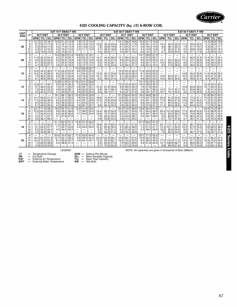
87
42D COOLING CAPACITY (by ΔT) 6-ROW COIL
LEGEND NOTE: All capacities are given in thousands of Btuh (MBtuh).
UNITSIZE ΔT
EAT 75 F DB/63 F WB EAT 80 F DB/67 F WB EAT 85 F DB/71 F WB40 F EWT 45 F EWT 50 F EWT 40 F EWT 45 F EWT 50 F EWT 40 F EWT 45 F EWT 50 F EWT
GPM TCb SCb GPM TCb SCb GPM TCb SCb GPM TCb SCb GPM TCb SCb GPM TCb SCb GPM TCb SCb GPM TCb SCb GPM TCb SCb
06
4 13.7 27.3 18.7 10.8 21.4 15.9 7.8 15.7 13.4 — — — 14.1 28.2 18.6 10.9 21.7 15.9 — — — — — — 14.4 28.9 18.66 8.7 25.7 17.9 6.7 19.7 15.2 4.9 14.6 12.9 10.9 32.5 20.6 8.9 26.3 17.8 6.8 20.1 15.3 13.4 40.0 23.3 11.3 33.6 20.5 9.1 26.9 17.88 5.9 23.6 17.0 4.5 17.9 14.4 3.4 13.6 12.2 7.8 30.8 19.8 6.1 24.5 17.1 4.6 18.4 14.6 9.6 38.1 22.4 7.9 31.7 19.7 6.3 25.1 17.1
10 4.3 21.4 15.9 3.3 16.2 13.5 2.2 11.1 10.8 5.7 28.5 18.8 4.5 22.2 16.1 3.4 16.8 13.8 7.3 36.3 21.6 6.0 29.8 18.9 4.6 22.9 16.212 3.3 19.3 15.0 2.5 14.8 12.7 — — — 4.4 26.0 17.7 3.4 20.1 15.2 2.6 15.4 13.1 5.7 33.9 20.6 4.6 27.1 17.8 3.3 20.6 15.4
08
4 — — — 14.5 29.2 21.6 10.8 21.4 18.1 — — — — — — 14.7 29.6 21.5 — — — — — — — — —6 11.8 35.2 24.4 9.2 27.3 20.7 6.9 20.3 17.6 14.7 44.4 28.0 12.1 36.2 24.3 9.3 27.6 20.7 — — — 15.1 46.0 27.8 12.4 37.1 24.18 8.3 33.3 23.5 6.3 25.5 19.9 4.8 19.2 16.9 10.6 42.3 27.0 8.6 34.0 23.3 6.6 25.9 20.0 13.1 52.2 30.5 11.0 43.7 26.8 8.8 34.7 23.2
10 6.1 30.8 22.3 4.7 23.4 18.9 3.2 15.9 15.5 8.0 40.3 26.1 6.4 31.7 22.3 4.8 24.1 19.1 10.0 50.0 29.5 8.3 41.4 25.9 6.6 32.5 22.412 4.7 28.2 21.1 3.6 21.6 18.0 2.3 13.7 13.7 6.2 37.6 24.9 4.9 29.3 21.3 3.8 22.3 18.3 8.0 47.8 28.6 6.6 39.0 24.9 5.0 30.2 21.5
10
4 — — — — — — 13.5 26.9 22.7 — — — — — — — — — — — — — — — — — —6 14.6 44.2 30.5 11.5 34.3 25.9 8.6 25.5 22.0 — — — 14.9 45.4 30.4 11.6 34.8 25.9 — — — — — — — — —8 10.5 41.9 29.4 8.0 32.2 25.0 6.1 24.4 21.3 13.3 53.1 33.8 10.8 42.9 29.3 8.1 32.6 25.0 — — — 13.8 55.0 33.6 11.0 43.8 29.2
10 7.9 39.5 28.3 6.0 30.1 24.0 4.0 19.9 19.9 10.1 50.7 32.7 8.1 40.4 28.2 6.1 30.8 24.2 12.6 62.9 37.1 10.5 52.3 32.5 8.2 41.0 28.112 6.1 36.6 26.9 4.7 28.0 22.9 3.0 18.2 18.2 8.0 48.2 31.6 6.3 37.8 27.1 4.8 28.9 23.3 10.0 60.3 35.9 8.2 49.6 31.4 6.4 38.6 27.2
12
6 — — — 13.9 41.8 31.4 10.4 31.0 26.6 — — — — — — 14.1 42.3 31.4 — — — — — — — — —8 12.8 51.1 35.7 9.9 39.4 30.3 7.6 29.8 25.9 — — — 13.2 52.4 35.5 10.0 39.9 30.3 — — — — — — 13.4 53.5 35.4
10 9.7 48.4 34.4 7.5 37.1 29.2 5.8 28.7 25.1 12.3 61.9 39.8 9.9 49.5 34.3 7.6 37.8 29.4 — — — 12.8 63.9 39.5 10.1 50.4 34.212 7.6 45.5 33.0 5.8 34.8 28.1 3.8 22.6 22.6 9.9 59.1 38.4 7.8 46.5 33.0 6.0 35.7 28.5 12.2 73.7 43.7 10.1 60.8 38.2 7.9 47.4 33.014 6.0 42.4 31.6 4.7 32.6 27.0 2.9 20.3 20.3 8.0 56.1 37.1 6.2 43.7 31.8 4.8 33.7 27.5 10.1 70.7 42.4 8.2 57.6 36.9 6.3 44.5 31.9
14
6 — — — 16.1 48.1 36.3 10.9 35.9 30.8 — — — 21.2 63.6 42.5 16.2 48.8 36.3 — — — — — — 21.8 65.2 42.38 14.7 58.6 41.2 11.2 45.1 35.0 7.6 34.4 30.2 18.6 74.4 47.4 14.6 60.1 41.0 11.0 45.7 35.0 22.9 91.6 53.5 19.3 77.0 47.1 15.0 61.3 40.9
10 11.0 54.8 39.4 8.5 42.0 33.5 6.4 32.7 28.8 14.2 70.9 45.8 10.9 56.5 39.5 8.5 43.1 33.8 17.6 88.0 51.9 14.6 73.2 45.5 11.2 57.5 39.412 8.5 50.6 37.4 6.6 39.0 32.0 4.1 24.0 24.0 11.1 67.0 44.0 8.7 52.5 37.7 6.8 40.4 32.6 14.1 84.3 50.2 11.6 69.1 43.9 9.0 53.9 37.914 6.7 46.6 35.5 5.2 36.8 30.8 2.9 20.7 20.7 8.9 62.4 42.0 6.9 48.5 36.0 5.5 37.8 31.2 11.4 80.6 48.6 9.2 64.9 42.2 7.1 50.2 36.5
16
6 23.7 71.5 49.2 18.6 55.7 41.8 13.9 41.6 35.5 — — — 24.3 73.5 49.0 18.8 56.4 41.8 — — — — — — 24.8 75.3 48.710 12.9 64.3 45.8 9.9 49.2 38.8 7.7 38.2 33.3 16.4 82.3 52.9 13.2 65.7 45.6 10.1 50.4 39.2 20.4 101.8 59.9 17.0 84.9 52.6 13.4 66.9 45.514 7.7 55.4 41.6 6.2 42.9 35.6 3.7 24.9 24.9 10.6 73.7 49.0 8.3 57.5 42.0 6.5 44.7 36.4 13.4 93.9 56.3 10.9 75.9 48.9 8.5 59.1 42.418 5.2 47.1 37.7 3.1 27.9 27.6 — — — 7.0 63.5 44.5 5.4 49.6 38.7 3.4 30.7 29.2 9.3 83.9 52.1 7.3 66.2 45.0 5.6 52.1 39.822 3.5 38.1 32.4 — — — — — — 4.9 53.8 40.3 3.9 41.2 34.0 — — — 6.7 72.7 47.6 5.1 56.7 41.3 4.2 44.5 35.6
18
6 — — — 21.1 63.3 47.4 15.8 47.3 40.2 — — — — — — 21.3 64.2 47.3 — — — — — — — — —10 14.7 73.5 52.0 11.2 56.3 44.1 8.3 41.2 37.5 18.8 93.7 60.0 15.0 75.1 51.8 11.4 57.6 44.5 23.1 115.7 67.9 19.4 96.7 59.6 15.3 76.5 51.614 9.1 64.2 47.7 7.1 49.7 40.8 4.3 29.5 29.5 12.2 84.9 56.0 9.4 66.3 48.0 7.3 51.5 41.7 15.3 107.1 64.0 12.5 87.5 55.9 9.8 68.0 48.318 6.2 55.3 43.4 4.5 40.4 35.5 — — — 8.3 74.3 51.4 6.5 57.8 44.2 5.3 48.3 39.6 10.8 96.8 59.6 8.6 77.1 51.7 6.7 60.2 45.122 4.3 45.8 38.1 — — — — — — 5.6 63.8 47.0 4.6 49.2 39.8 — — — 7.6 85.3 54.9 5.8 66.7 47.9 4.8 52.7 41.6
20
6 — — — 23.4 70.4 52.7 17.5 52.6 44.6 — — — — — — 23.7 71.3 52.5 — — — — — — — — —10 16.3 81.9 57.9 12.7 63.1 49.3 9.9 49.0 42.3 20.9 104.3 66.7 16.8 83.7 57.6 12.9 64.2 49.5 — — — 21.5 107.6 66.3 17.1 85.2 57.414 10.4 72.3 53.3 8.1 56.0 45.7 4.9 34.1 34.1 13.5 95.3 62.7 10.6 74.2 53.5 8.4 58.0 46.5 17.0 119.3 71.2 14.0 97.7 62.2 10.9 76.2 53.818 7.0 62.8 48.8 5.5 48.8 41.4 — — — 9.3 83.9 57.6 7.2 65.2 49.6 5.9 51.8 42.9 12.1 108.8 66.7 9.5 86.6 60.3 7.6 67.7 50.422 4.9 53.2 43.8 — — — — — — 6.7 72.6 52.6 5.1 57.0 45.8 — — — 8.8 96.8 61.8 6.9 75.7 43.9 5.5 60.1 46.9
ΔT — Temperature Change GPM — Gallons Per MinuteDB — Dry Bulb SCb — Base Sensible CapacityEAT — Entering Air Temperature TCb — Base Total CapacityEWT — Entering Water Temperature WB — Wet Bulb
42
D S
eries Units
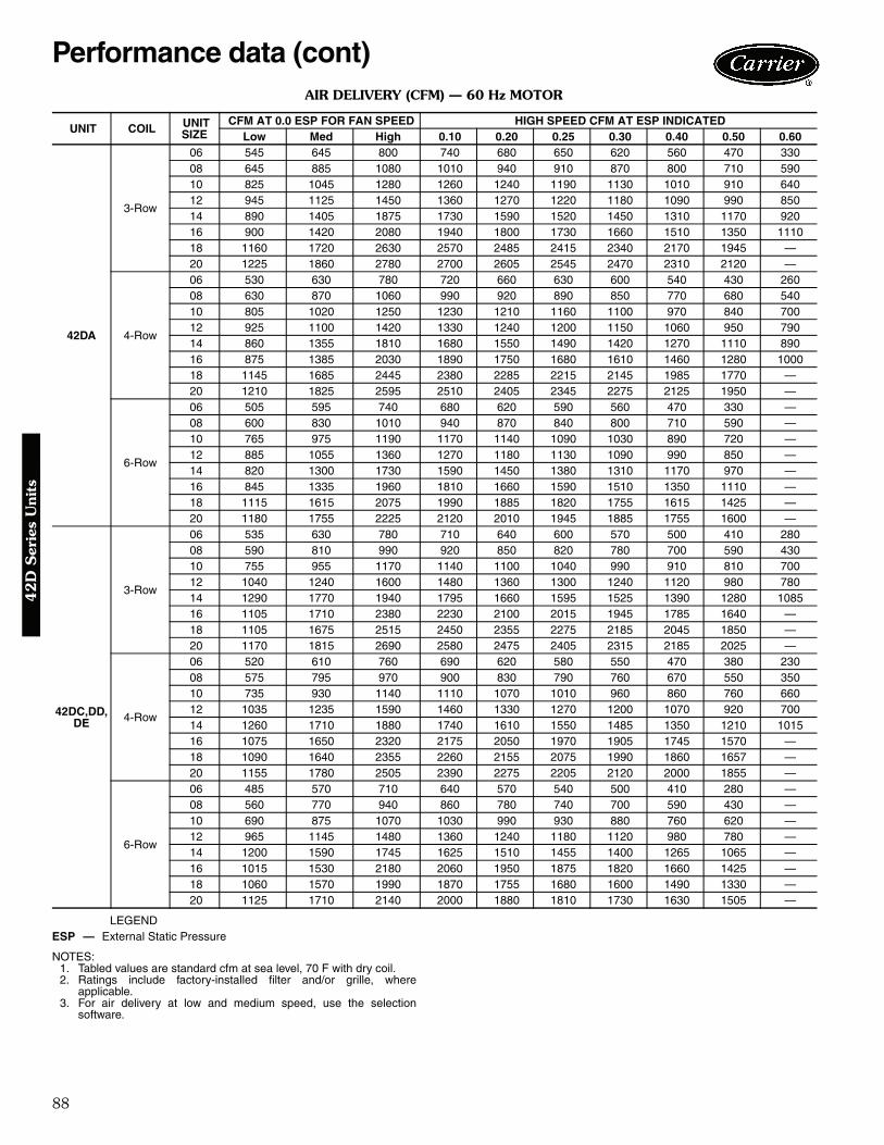
88
AIR DELIVERY (CFM) — 60 Hz MOTOR
LEGEND
NOTES:1. Tabled values are standard cfm at sea level, 70 F with dry coil.2. Ratings include factory-installed filter and/or grille, where
applicable.3. For air delivery at low and medium speed, use the selection
software.
UNIT COIL UNITSIZE
CFM AT 0.0 ESP FOR FAN SPEED HIGH SPEED CFM AT ESP INDICATED Low Med High 0.10 0.20 0.25 0.30 0.40 0.50 0.60
42DA
3-Row
06 545 645 800 740 680 650 620 560 470 330 08 645 885 1080 1010 940 910 870 800 710 590 10 825 1045 1280 1260 1240 1190 1130 1010 910 640 12 945 1125 1450 1360 1270 1220 1180 1090 990 850 14 890 1405 1875 1730 1590 1520 1450 1310 1170 920 16 900 1420 2080 1940 1800 1730 1660 1510 1350 1110 18 1160 1720 2630 2570 2485 2415 2340 2170 1945 — 20 1225 1860 2780 2700 2605 2545 2470 2310 2120 —
4-Row
06 530 630 780 720 660 630 600 540 430 260 08 630 870 1060 990 920 890 850 770 680 540 10 805 1020 1250 1230 1210 1160 1100 970 840 700 12 925 1100 1420 1330 1240 1200 1150 1060 950 790 14 860 1355 1810 1680 1550 1490 1420 1270 1110 890 16 875 1385 2030 1890 1750 1680 1610 1460 1280 1000 18 1145 1685 2445 2380 2285 2215 2145 1985 1770 — 20 1210 1825 2595 2510 2405 2345 2275 2125 1950 —
6-Row
06 505 595 740 680 620 590 560 470 330 — 08 600 830 1010 940 870 840 800 710 590 — 10 765 975 1190 1170 1140 1090 1030 890 720 — 12 885 1055 1360 1270 1180 1130 1090 990 850 — 14 820 1300 1730 1590 1450 1380 1310 1170 970 — 16 845 1335 1960 1810 1660 1590 1510 1350 1110 — 18 1115 1615 2075 1990 1885 1820 1755 1615 1425 — 20 1180 1755 2225 2120 2010 1945 1885 1755 1600 —
42DC,DD,DE
3-Row
06 535 630 780 710 640 600 570 500 410 280 08 590 810 990 920 850 820 780 700 590 430 10 755 955 1170 1140 1100 1040 990 910 810 700 12 1040 1240 1600 1480 1360 1300 1240 1120 980 780 14 1290 1770 1940 1795 1660 1595 1525 1390 1280 1085 16 1105 1710 2380 2230 2100 2015 1945 1785 1640 — 18 1105 1675 2515 2450 2355 2275 2185 2045 1850 — 20 1170 1815 2690 2580 2475 2405 2315 2185 2025 —
4-Row
06 520 610 760 690 620 580 550 470 380 230 08 575 795 970 900 830 790 760 670 550 350 10 735 930 1140 1110 1070 1010 960 860 760 660 12 1035 1235 1590 1460 1330 1270 1200 1070 920 700 14 1260 1710 1880 1740 1610 1550 1485 1350 1210 1015 16 1075 1650 2320 2175 2050 1970 1905 1745 1570 — 18 1090 1640 2355 2260 2155 2075 1990 1860 1657 — 20 1155 1780 2505 2390 2275 2205 2120 2000 1855 —
6-Row
06 485 570 710 640 570 540 500 410 280 — 08 560 770 940 860 780 740 700 590 430 — 10 690 875 1070 1030 990 930 880 760 620 — 12 965 1145 1480 1360 1240 1180 1120 980 780 — 14 1200 1590 1745 1625 1510 1455 1400 1265 1065 — 16 1015 1530 2180 2060 1950 1875 1820 1660 1425 — 18 1060 1570 1990 1870 1755 1680 1600 1490 1330 — 20 1125 1710 2140 2000 1880 1810 1730 1630 1505 —
ESP — External Static Pressure
Performance data (cont)4
2D
Ser
ies
Uni
ts

89
AIR DELIVERY (CFM) — 60 Hz MOTOR (cont)
LEGEND NOTES:1. Tabled values are standard cfm at sea level, 70 F with dry coil.2. Ratings include factory-installed filter and/or grille, where applicable.3. For air delivery at low and medium speed, use the selection software.
42D SERIES COOLING CAPACITY CORRECTION FACTORS
LEGEND
NOTE: Use sensible heat correction factors when calculating heating capacity.
UNIT COIL UNITSIZE
CFM AT 0.0 ESP FOR FAN SPEED HIGH SPEED CFM AT ESP INDICATED Low Med High 0.10 0.20 0.25 0.30 0.40 0.50 0.60
42DF
3-Row
06 465 545 680 — — — — — — — 08 490 670 820 — — — — — — — 10 660 835 1020 — — — — — — — 12 810 960 1240 — — — — — — — 14 700 1105 1470 — — — — — — — 16 685 1085 1590 — — — — — — — 18 1155 1505 1800 — — — — — — — 20 1280 1675 2030 — — — — — — —
4-Row
06 460 540 670 — — — — — — — 08 480 665 810 — — — — — — — 10 645 820 1000 — — — — — — — 12 795 945 1220 — — — — — — — 14 680 1090 1450 — — — — — — — 16 680 1070 1570 — — — — — — — 18 1140 1485 1780 — — — — — — — 20 1260 1650 2000 — — — — — — —
6-Row
06 445 520 650 — — — — — — — 08 465 640 780 — — — — — — — 10 620 785 960 — — — — — — — 12 775 925 1190 — — — — — — — 14 665 1050 1400 — — — — — — — 16 650 1030 1510 — — — — — — — 18 1090 1420 1700 — — — — — — — 20 1225 1600 1940 — — — — — — —
ESP — External Static Pressure
ACTUALCFM
UNIT SIZE06 08 10 12 14 16 18 20
TH SH TH SH TH SH TH SH TH SH TH SH TH SH TH SH100 — — — — — — — — — — — — — — — —125 — — — — — — — — — — — — — — — —150 — — — — — — — — — — — — — — — —175 — — — — — — — — — — — — — — — —200 0.46 0.41 — — — — — — — — — — — — — —225 0.51 0.45 — — — — — — — — — — — — — —250 0.55 0.49 — — — — — — — — — — — — — —275 0.58 0.53 0.47 0.42 — — — — — — — — — — — —300 0.62 0.57 0.51 0.45 0.43 0.38 — — — — — — — — — —350 0.69 0.65 0.57 0.50 0.48 0.46 — — — — — — — — — —400 0.76 0.73 0.62 0.57 0.53 0.47 0.46 0.41 — — — — — — — —450 0.82 0.80 0.67 0.63 0.58 0.52 0.51 0.45 — — — — — — — —500 0.89 0.87 0.72 0.69 0.62 0.57 0.55 0.47 — — — — — — — —550 0.95 0.94 0.77 0.74 0.66 0.62 0.58 0.53 0.57 0.47 — — — — — —600 1.00 1.00 0.82 0.80 0.70 0.67 0.62 0.57 0.58 0.53 — — — — — —700 1.11 1.12 0.92 0.91 0.78 0.76 0.69 0.65 0.62 0.57 0.57 0.50 — — — —800 1.18 1.22 1.00 1.00 0.86 0.85 0.76 0.73 0.68 0.64 0.62 0.57 0.57 0.51 — —900 — — 1.08 1.08 0.94 0.93 0.82 0.80 0.74 0.71 0.67 0.63 0.62 0.57 0.58 0.52
1000 — — 1.16 1.18 1.00 1.00 0.89 0.87 0.82 0.80 0.72 0.69 0.68 0.65 0.62 0.571200 — — — — 1.13 1.14 1.00 1.00 0.90 0.89 0.82 0.80 0.76 0.72 0.70 0.671400 — — — — — — 1.11 1.12 1.00 1.00 0.92 0.91 0.84 0.82 0.78 0.761600 — — — — — — 1.18 1.22 1.10 1.11 1.00 1.00 0.93 0.92 0.86 0.851800 — — — — — — — — — — 1.08 1.08 1.00 1.00 0.94 0.932000 — — — — — — — — — — 1.16 1.18 1.07 1.07 1.00 1.002200 — — — — — — — — — — — — — — 1.07 1.072400 — — — — — — — — — — — — — — 1.13 1.14
SH — Sensible HeatTH — Total Heat
42
D S
eries Units
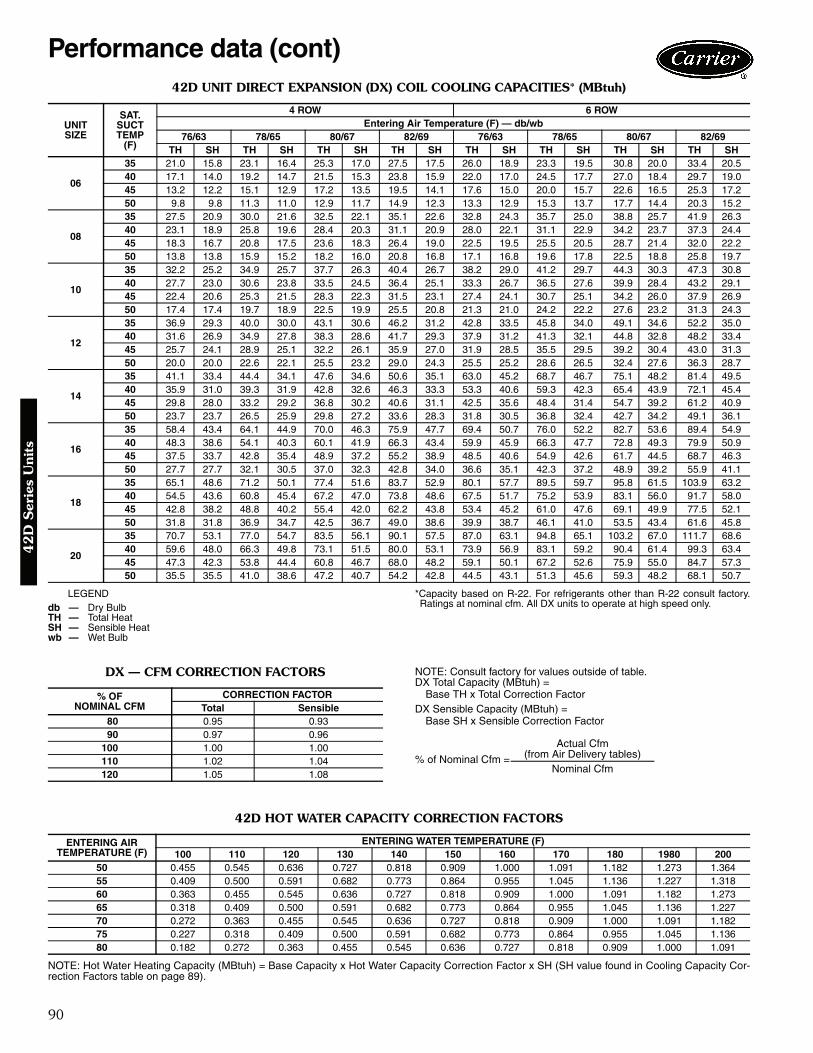
90
42D UNIT DIRECT EXPANSION (DX) COIL COOLING CAPACITIES* (MBtuh)
LEGEND *Capacity based on R-22. For refrigerants other than R-22 consult factory.Ratings at nominal cfm. All DX units to operate at high speed only.
DX — CFM CORRECTION FACTORS NOTE: Consult factory for values outside of table.DX Total Capacity (MBtuh) =
Base TH x Total Correction FactorDX Sensible Capacity (MBtuh) =
Base SH x Sensible Correction Factor
42D HOT WATER CAPACITY CORRECTION FACTORS
NOTE: Hot Water Heating Capacity (MBtuh) = Base Capacity x Hot Water Capacity Correction Factor x SH (SH value found in Cooling Capacity Cor-rection Factors table on page 89).
UNITSIZE
SAT.SUCTTEMP
(F)
4 ROW 6 ROWEntering Air Temperature (F) — db/wb
76/63 78/65 80/67 82/69 76/63 78/65 80/67 82/69TH SH TH SH TH SH TH SH TH SH TH SH TH SH TH SH
06
35 21.0 15.8 23.1 16.4 25.3 17.0 27.5 17.5 26.0 18.9 23.3 19.5 30.8 20.0 33.4 20.540 17.1 14.0 19.2 14.7 21.5 15.3 23.8 15.9 22.0 17.0 24.5 17.7 27.0 18.4 29.7 19.045 13.2 12.2 15.1 12.9 17.2 13.5 19.5 14.1 17.6 15.0 20.0 15.7 22.6 16.5 25.3 17.250 9.8 9.8 11.3 11.0 12.9 11.7 14.9 12.3 13.3 12.9 15.3 13.7 17.7 14.4 20.3 15.2
08
35 27.5 20.9 30.0 21.6 32.5 22.1 35.1 22.6 32.8 24.3 35.7 25.0 38.8 25.7 41.9 26.340 23.1 18.9 25.8 19.6 28.4 20.3 31.1 20.9 28.0 22.1 31.1 22.9 34.2 23.7 37.3 24.445 18.3 16.7 20.8 17.5 23.6 18.3 26.4 19.0 22.5 19.5 25.5 20.5 28.7 21.4 32.0 22.250 13.8 13.8 15.9 15.2 18.2 16.0 20.8 16.8 17.1 16.8 19.6 17.8 22.5 18.8 25.8 19.7
10
35 32.2 25.2 34.9 25.7 37.7 26.3 40.4 26.7 38.2 29.0 41.2 29.7 44.3 30.3 47.3 30.840 27.7 23.0 30.6 23.8 33.5 24.5 36.4 25.1 33.3 26.7 36.5 27.6 39.9 28.4 43.2 29.145 22.4 20.6 25.3 21.5 28.3 22.3 31.5 23.1 27.4 24.1 30.7 25.1 34.2 26.0 37.9 26.950 17.4 17.4 19.7 18.9 22.5 19.9 25.5 20.8 21.3 21.0 24.2 22.2 27.6 23.2 31.3 24.3
12
35 36.9 29.3 40.0 30.0 43.1 30.6 46.2 31.2 42.8 33.5 45.8 34.0 49.1 34.6 52.2 35.040 31.6 26.9 34.9 27.8 38.3 28.6 41.7 29.3 37.9 31.2 41.3 32.1 44.8 32.8 48.2 33.445 25.7 24.1 28.9 25.1 32.2 26.1 35.9 27.0 31.9 28.5 35.5 29.5 39.2 30.4 43.0 31.350 20.0 20.0 22.6 22.1 25.5 23.2 29.0 24.3 25.5 25.2 28.6 26.5 32.4 27.6 36.3 28.7
14
35 41.1 33.4 44.4 34.1 47.6 34.6 50.6 35.1 63.0 45.2 68.7 46.7 75.1 48.2 81.4 49.540 35.9 31.0 39.3 31.9 42.8 32.6 46.3 33.3 53.3 40.6 59.3 42.3 65.4 43.9 72.1 45.445 29.8 28.0 33.2 29.2 36.8 30.2 40.6 31.1 42.5 35.6 48.4 31.4 54.7 39.2 61.2 40.950 23.7 23.7 26.5 25.9 29.8 27.2 33.6 28.3 31.8 30.5 36.8 32.4 42.7 34.2 49.1 36.1
16
35 58.4 43.4 64.1 44.9 70.0 46.3 75.9 47.7 69.4 50.7 76.0 52.2 82.7 53.6 89.4 54.940 48.3 38.6 54.1 40.3 60.1 41.9 66.3 43.4 59.9 45.9 66.3 47.7 72.8 49.3 79.9 50.945 37.5 33.7 42.8 35.4 48.9 37.2 55.2 38.9 48.5 40.6 54.9 42.6 61.7 44.5 68.7 46.350 27.7 27.7 32.1 30.5 37.0 32.3 42.8 34.0 36.6 35.1 42.3 37.2 48.9 39.2 55.9 41.1
18
35 65.1 48.6 71.2 50.1 77.4 51.6 83.7 52.9 80.1 57.7 89.5 59.7 95.8 61.5 103.9 63.240 54.5 43.6 60.8 45.4 67.2 47.0 73.8 48.6 67.5 51.7 75.2 53.9 83.1 56.0 91.7 58.045 42.8 38.2 48.8 40.2 55.4 42.0 62.2 43.8 53.4 45.2 61.0 47.6 69.1 49.9 77.5 52.150 31.8 31.8 36.9 34.7 42.5 36.7 49.0 38.6 39.9 38.7 46.1 41.0 53.5 43.4 61.6 45.8
20
35 70.7 53.1 77.0 54.7 83.5 56.1 90.1 57.5 87.0 63.1 94.8 65.1 103.2 67.0 111.7 68.640 59.6 48.0 66.3 49.8 73.1 51.5 80.0 53.1 73.9 56.9 83.1 59.2 90.4 61.4 99.3 63.445 47.3 42.3 53.8 44.4 60.8 46.7 68.0 48.2 59.1 50.1 67.2 52.6 75.9 55.0 84.7 57.350 35.5 35.5 41.0 38.6 47.2 40.7 54.2 42.8 44.5 43.1 51.3 45.6 59.3 48.2 68.1 50.7
db — Dry BulbTH — Total HeatSH — Sensible Heatwb — Wet Bulb
% OFNOMINAL CFM
CORRECTION FACTORTotal Sensible
80 0.95 0.9390 0.97 0.96
100 1.00 1.00110 1.02 1.04120 1.05 1.08
% of Nominal Cfm =
Actual Cfm(from Air Delivery tables)
Nominal Cfm
ENTERING AIRTEMPERATURE (F)
ENTERING WATER TEMPERATURE (F)100 110 120 130 140 150 160 170 180 1980 200
50 0.455 0.545 0.636 0.727 0.818 0.909 1.000 1.091 1.182 1.273 1.36455 0.409 0.500 0.591 0.682 0.773 0.864 0.955 1.045 1.136 1.227 1.31860 0.363 0.455 0.545 0.636 0.727 0.818 0.909 1.000 1.091 1.182 1.27365 0.318 0.409 0.500 0.591 0.682 0.773 0.864 0.955 1.045 1.136 1.22770 0.272 0.363 0.455 0.545 0.636 0.727 0.818 0.909 1.000 1.091 1.18275 0.227 0.318 0.409 0.500 0.591 0.682 0.773 0.864 0.955 1.045 1.13680 0.182 0.272 0.363 0.455 0.545 0.636 0.727 0.818 0.909 1.000 1.091
Performance data (cont)4
2D
Ser
ies
Uni
ts

91
42D HOT WATER HEATING CAPACITIES (MBtuh)
NOTE: Ratings based on nominal cfm, 70 F entering dry bulb, 180 Fentering water temperature.
42D STEAM COILHEATING CAPACITIES (Btuh)
NOTES:1. Ratings based on nominal cfm, 70 F entering dry bulb, 2 psig steam.2. All capacities above 50,000 Btuh rating are beyond the capacity of
the standard control valve. Consult factory for these applications.
Cv FACTOR BY COIL AND UNIT SIZE
ROWS UNITSIZE
GPM0.5 1.0 1.5 2.0 2.5 3.0 3.5 4.0 5.0 6.0 7.0 8.0 9.0 10.0 11.0
1ROW
06 13.5 17.5 19.5 20.5 21.3 21.8 22.2 22.5 — — — — — — —08 16.0 22.0 24.6 26.5 27.9 29.0 29.5 29.9 — — — — — — —10 — 25.5 29.0 31.2 32.7 34.0 34.8 35.5 — — — — — — —12 — 29.0 33.6 36.3 38.2 39.8 40.9 41.7 — — — — — — —14 — 31.5 37.7 41.0 43.5 45.5 46.8 48.0 — — — — — — —16 — 34.0 41.2 45.3 48.4 51.0 52.8 54.2 — — — — — — —18 — 36.0 44.5 49.6 53.1 55.9 58.0 59.7 — — — — — — —20 — 38.0 47.5 52.9 56.9 60.3 62.8 64.7 — — — — — — —
2ROW
06 — 24.5 — 30.7 — 33.5 — 35.2 36.0 — — — — — —08 — 29.5 — 38.7 — 42.9 — 45.3 46.5 — — — — — —10 — 33.5 — 45.4 — 50.7 — 54.4 56.7 68.2 69.3 — — — —12 — 36.5 — 51.5 — 59.0 — 63.3 66.2 68.7 70.2 71.2 — — —14 — 39.3 — 56.8 — 66.2 — 71.9 75.7 78.4 80.5 82.0 — — —16 — 41.0 — 61.9 — 73.5 — 80.2 84.8 87.9 90.3 92.3 — — —18 — — — 66.5 — 79.6 — 87.9 93.3 97.2 100.0 102.3 — — —20 — — — 70.0 — 84.5 — 93.6 100.5 105.2 108.7 111.4 — — —
4ROW
06 — — — 40.2 — 45.0 — 47.9 49.5 50.8 51.5 — — — —08 — — — 47.8 — 56.7 — 60.9 63.5 65.5 67.4 — — — —10 — — — 57.3 — 66.4 — 72.3 76.6 79.5 81.5 83.0 84.4 — —12 — — — 64.0 — 76.4 — 83.7 88.8 92.2 95.3 97.7 99.4 — —14 — — — — — 82.9 — 92.0 98.3 103.0 106.6 109.5 112.0 — —16 — — — — — 89.4 — 100.5 109.3 115.2 119.4 122.7 125.8 — —18 — — — — — 95.7 — 109.0 109.3 126.1 131.2 135.2 138.6 — —20 — — — — — 101.3 — 116.2 128.1 136.2 142.3 145.9 151.0 — —
6ROW
06 — — — — — — — 54.6 56.5 57.7 58.6 59.4 60.0 — —08 — — — — — — — 68.9 72.2 74.5 76.3 77.6 78.5 — —10 — — — — — — — 81.9 86.3 89.6 92.2 94.1 95.5 96.7 97.712 — — — — — — — 94.0 99.8 104.0 107.3 110.4 112.4 114.1 115.414 — — — — — — — 102.4 111.0 116.8 121.0 124.2 126.9 129.5 131.516 — — — — — — — 111.6 122.3 129.4 134.5 138.6 142.0 145.2 147.518 — — — — — — — 119.5 133.0 141.2 147.2 152.2 156.3 160.3 163.420 — — — — — — — 128.0 142.3 152.1 158.0 164.7 169.6 174.0 177.5
UNITSIZE
70 F ENTERING AIR TEMPERATURE1-Row Coil 2-Row Coil
06 28,900 52,50008 38,400 70,00010 46,000 86,00012 55,800 103,90014 65,100 121,20016 74,400 138,50018 83,700 155,80020 92,100 172,000
COIL TYPE42DA,DC,DD,DE,DF
UNIT SIZE06 08 10 12 14 16 18 20
1 Row — Heat Only 1.4 1.3 1.2 1.2 1.1 1.1 1.0 1.02 Row — Heat Only 2.5 2.4 2.3 2.2 2.1 2.0 2.0 1.93 Row — Heat or Cool 2.1 2.0 3.6 3.3 4.7 4.6 4.7 4.64 Row — Heat or Cool 4.0 3.9 4.6 4.5 7.6 7.4 7.2 7.06 Row — Heat or Cool 4.3 4.1 3.9 3.7 6.5 6.3 6.1 5.9
42
D S
eries Units

92
42D ELECTRIC HEATER DATA
LEGENDFLA — Full Load AmpsNOTES:1. All heaters are single-stage and single-phase.2. In all units using over 48 amps, the heating elements are sub-
divided and protected. Additional cost is incurred because of addedcomponents.
3. A separate power source is required for motor and heaters exceptwhen motors and heaters of same voltage are ordered in conjunctionwith a single power source wiring option. This option, which meetsNEC (National Electric Code) requirements, consists of a factory-furnished and installed junction box and fuse for 6.25 amp (max) fanand control circuit connection to a single power source. Power sup-ply circuit to unit must be field furnished and installed in accordancewith applicable codes.
42DA MOTOR DATA
*Total motor amps and watts shown for units with 2 motors (size 12 through 20).NOTES:
1. Motor nameplate amps may vary.2. Fan coil units comply with UL, Canadian Standards Association (CSA), and
Underwriters Laboratories of Canada standards.
HEATERVOLTAGE
HEATER kW2.0 3.0 4.0 5.0 6.0 7.0 8.0 9.0 10.0 12.0 14.0
FLA120 16.7 25.0 — — — — — — — — —208 9.6 14.4 19.2 24.0 28.8 33.7 38.5 43.3 48.1 57.7 67.3240 8.3 12.5 16.7 20.8 25.0 29.2 33.3 37.5 41.7 50.0 58.3277 7.2 10.8 14.4 18.0 21.7 25.3 28.9 32.5 36.1 43.3 50.5
V-Ph-Hz FANSPEED
FANSPEED(RPM)
UNIT SIZE
06 08 10 12*
Nominal Hp Watts Amps Nominal
Hp Watts Amps Nominal Hp Watts Amps Nominal
Hp Watts Amps
115-1-60H 1200
1/10
280 2.701/8
330 3.101/5
470 5.601/10 (2)
550 5.30M 980 200 2.00 225 2.25 360 3.70 305 2.92L 790 140 1.50 135 1.44 240 2.60 205 1.93
208/230-1-60H 1200
1/10
240 1.101/8
420 1.801/5
430 2.001/10 (2)
450 2.10M 980 175 0.74 280 1.26 260 1.20 325 1.45L 790 110 0.50 155 0.73 165 0.80 215 1.00
277-1-60H 1200
1/10
275 1.151/8
275 1.211/5
425 1.621/10 (2)
550 2.40M 980 175 0.69 175 0.69 260 1.04 355 1.38L 790 90 0.33 90 0.34 155 0.65 175 0.67
V-Ph-Hz FANSPEED
FANSPEED(RPM)
UNIT SIZE
14* 16* 18* 20*
Nominal Hp Watts Amps Nominal
Hp Watts Amps Nominal Hp Watts Amps Nominal
Hp Watts Amps
115-1-60H 1200
1/10 (2)650 6.40
1/5 (2)900 8.80
1/5 (2)1180 11.80
1/4 (2)1180 11.80
M 980 440 4.60 705 6.90 770 8.30 770 8.30L 790 280 3.00 430 4.20 460 5.30 460 5.30
208/230-1-60H 1200
1/10 (2)465 2.10
1/5 (2)740 3.60
1/5 (2)925 4.10
1/4 (2)925 4.10
M 980 325 1.45 360 1.80 5.45 2.48 545 2.48L 790 220 1.00 220 1.20 330 1.60 330 1.60
277-1-60H 1200
1/10 (2)735 2.70
1/5 (2)940 3.60
1/5 (2)980 3.72
1/4 (2)980 3.72
M 980 510 1.90 560 2.20 550 2.20 550 2.20L 790 330 1.30 335 1.40 320 1.40 320 1.40
Electrical data4
2D
Ser
ies
Uni
ts

93
42DC,DD AND DE MOTOR DATA
*Total motor amps and watts shown for units with 2 motors (size 12 through20).NOTES:
1. Motor nameplate amps may vary.2. Fan coil units comply with UL, Canadian Standards Association (CSA),
and Underwriters Laboratories of Canada standards.
V-Ph-Hz FANSPEED
FANSPEED(RPM)
UNIT SIZE
06 08 10 12*
Nominal Hp Watts Amps Nominal
Hp Watts Amps Nominal Hp Watts Amps Nominal
Hp Watts Amps
115-1-60H 1200
1/10
265 2.601/8
310 3.001/5
440 4.501/10 (2)
550 5.40M 980 195 1.95 220 2.30 330 3.40 390 3.90L 790 155 1.54 140 1.50 225 2.50 305 3.10
208/230-1-60H 1200
1/10
235 1.001/8
325 1.451/5
410 1.801/10 (2)
700 3.20M 980 165 0.72 210 0.95 250 1.10 430 2.00L 790 110 0.49 135 0.62 160 0.76 305 1.48
277-1-60H 1200
1/10
275 1.101/8
275 1.401/5
395 1.511/10 (2)
535 2.40M 980 175 0.70 175 0.69 260 1.10 360 1.40L 790 90 0.33 90 0.34 155 0.65 190 0.70
V-Ph-Hz FANSPEED
FANSPEED(RPM)
UNIT SIZE
14* 16* 18* 20*
Nominal Hp Watts Amps Nominal
Hp Watts Amps Nominal Hp Watts Amps Nominal
Hp Watts Amps
115-1-60H 1200
1/10 (2)690 6.80
1/5 (2)900 9.80
1/5 (2)1015 10.20
1/4 (2)1020 10.20
M 980 560 5.40 725 7.70 745 7.80 750 7.80L 790 280 3.50 450 5.24 450 5.30 460 5.30
208/230-1-60H 1200
1/10 (2)720 3.30
1/5 (2)680 3.00
1/5 (2)820 3.70
1/4 (2)820 3.70
M 980 440 2.00 445 2.00 500 2.20 510 2.20L 790 310 1.48 285 1.33 330 1.50 330 1.50
277-1-60H 1200
1/10 (2)700 2.65
1/5 (2)830 3.20
1/5 (2)900 3.50
1/4 (2)925 3.52
M 980 495 1.96 510 2.00 550 2.23 550 2.23L 790 300 1.30 300 1.30 320 1.36 320 1.36
42
D S
eries Units
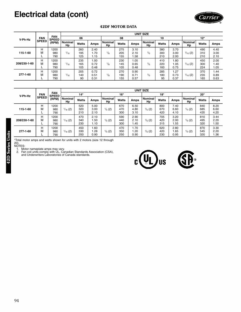
94
42DF MOTOR DATA
*Total motor amps and watts shown for units with 2 motors (size 12 through20).NOTES:
1. Motor nameplate amps may vary.2. Fan coil units comply with UL, Canadian Standards Association (CSA),
and Underwriters Laboratories of Canada standards.
V-Ph-Hz FANSPEED
FANSPEED(RPM)
UNIT SIZE06 08 10 12*
Nominal Hp Watts Amps Nominal
Hp Watts Amps Nominal Hp Watts Amps Nominal
Hp Watts Amps
115-1-60H 1200
1/10
260 2.401/8
275 3.101/5
380 3.701/10 (2)
490 4.40M 980 195 1.70 205 2.10 300 3.00 310 3.00L 790 125 1.15 155 1.58 210 2.00 210 2.10
208/230-1-60H 1200
1/10
235 1.001/8
230 1.051/5
410 1.801/10 (2)
450 2.00M 980 165 0.72 145 0.65 220 1.05 300 1.40L 790 105 0.48 105 0.48 160 0.75 224 1.05
277-1-60H 1200
1/10
205 0.721/8
270 0.901/5
285 1.271/10 (2)
370 1.44M 980 140 0.51 190 0.71 180 0.73 235 0.89L 790 90 0.31 155 0.57 95 0.37 165 0.63
V-Ph-Hz FANSPEED
FANSPEED(RPM)
UNIT SIZE14* 16* 18* 20*
Nominal Hp Watts Amps Nominal
Hp Watts Amps Nominal Hp Watts Amps Nominal
Hp Watts Amps
115-1-60H 1200
1/10 (2)520 5.00
1/5 (2)670 6.50
1/5 (2)800 7.40
1/4 (2)840 8.20
M 980 320 3.00 470 4.80 670 6.60 685 6.60L 790 210 2.10 300 3.10 420 4.10 435 4.20
208/230-1-60H 1200
1/10 (2)470 2.10
1/5 (2)590 2.90
1/5 (2)705 3.20
1/4 (2)810 3.44
M 980 340 1.50 440 2.10 420 2.00 495 2.20L 790 230 1.10 300 1.45 315 1.55 320 1.50
277-1-60H 1200
1/10 (2)450 1.60
1/5 (2)470 1.70
1/5 (2)620 2.80
1/4 (2)870 3.30
M 980 330 1.28 350 1.20 420 1.65 545 2.20L 790 250 0.90 250 0.90 230 0.95 320 1.36
Electrical data (cont)4
2D
Ser
ies
Uni
ts

95
ARI capacity ratingsThe 42S series fan coil units are certified in compliancewith the Air Conditioning and Refrigeration Institute (ARI)Industry Standard 440 for room fan coil units. Approvedstandard ratings are tabulated below:
ARI APPROVED STANDARD RATINGS — STANDARD CAPACITY COIL
*Table values are listed for each half of 42SJ units and master/slave.†Motor type, permanent split capacitor, operating at 115-1-60 voltage.
NOTE: Ratings based on motor at high fan speed, standard air and drycoil operation, 10 degrees F water temperature rise; entering air tem-peratures of 80 F db, 67 F wb; entering water temperature 45 F.
UNITTYPE*
UNIT SIZECOIL
NOMINALCFM GPM
COOLING CAPACITY POWER INPUT(WATTS)†Total Heat Btuh Sensible Heat Btuh
42S
03 300 2.4 11,500 7,000 8504 400 2.9 13,600 9,000 11506 600 4.5 21,900 14,000 13508 800 5.5 27,500 17,800 21010 1000 7.7 37,700 24,500 29012 1200 8.1 43,100 28,400 380
Model number nomenclature4
2S
Series U
nits
NOTE: Contact your local Carrier representative for unit specifications.
a42-3998

96
SOUND PRESSURE DATA42S SOUND RATINGS — OCTAVE BAND SOUND POWER LEVEL RATINGS* (dB)
*Testing per ARI Standard 350-2000.
Physical data
*Calculate Operating Weight of unit: Shipping Weight + Coil Water Weight x Number of Coil Rows.†42SJ units require two filters.
SIZE NOMINALCFM SPEED RPM
CENTER FREQUENCY — Hz125 250 500 1000 2000 4000 8000
03 300High 1075 64.5 57 52.5 49 41 39 35.5Medium 825 61.5 51.5 48.5 43.5 33.5 30.5 24.5Low 675 56 45.5 42.5 35.5 25.5 21 —
04 400High 1075 69 59.5 55.5 50.5 41.5 39.5 36.5Medium 850 64 52.5 48.5 43.5 33.5 30.5 24.5Low 650 57.5 46.5 42.5 35.5 25.5 21 —
06 600High 1075 71.5 60.5 57 52.5 44.5 42 39Medium 900 67.5 55.5 51 46.5 37 34.5 28.5Low 700 61 49 45 40 30 26 —
08 800High 1075 74 62 58.5 54 48.5 44 41Medium 900 71 57.5 54 49.5 42 38.5 33.5Low 675 65 51.5 48.5 43 34.5 29.5 21
10 1000High 1075 77 66.5 61.5 59 53 49.5 46Medium 900 74 64 58.5 55 48.5 46 41Low 700 67 59 55 51 45 40.5 35.5
12 1200High 1075 79 70 65.5 62 56.5 51.5 47.5Medium 925 76.5 66 62.5 58 52 47 42.5Low 775 70.5 62.5 59 54 47.5 41.5 37
UNIT SIZE 42S 03 04 06 08 10 12NOMINAL AIRFLOW (cfm) 300 400 600 800 1000 1200SHIPPING WEIGHT (lb)* 42SG 225 225 250 250 275 275 42SH 225 225 250 250 275 275 42SJ 420 420 470 470 520 520COIL WATER WEIGHT (Approx lb per row of coil) 1.6 1.6 2.3 2.3 3.1 3.1
COILS FPI 14 fins/inchMOTOR (qty) 42SG,SH 1 1 1 1 1 1 42SJ 2 2 2 2 2 2BLOWER (qty) 42SG,SH 1 1 1 1 1 1 42SJ 2 2 2 2 2 2FILTERSNominal Size (in.) (1-in. thick) 121/2 x 241/4 161/4 x 263/4 201/2 x 291/4
Qty 1†PIPING CONNECTIONS Inlet (in. OD) 1/2
ARI capacity ratings (cont)4
2S
Ser
ies
Uni
ts

97
Base unit dimensions4
2S
Series U
nits
42SG FURRED-IN STACK
*Drawing provided for reference only. Dimensions may vary with options ordered.NOTES:
1. Units are fabricated of 18-gage galvanized steel with a 16-gage galvanized fan deck.2. All risers are insulated with 1/2-in. closed cell insulation.3. Thermostats shipped loose for field connection.4. Risers are piped to coil with valves as specified.5. Blower, motor, valves, coil, and filter are accessible through the return air opening.6. Unit and control box are insulated with 1/2-in. coated fiberglass insulation.7. Riser length = [(floor to floor) +2 in.], maximum riser length = 115 inches.8. Maximum riser size is 21/2-in. diameter. If larger sizes are required, please consult the factory.9. Expansion loops in hot water heating circuits as required.
10. A 9-in. x 21/4-in. slot is provided in the inside back panel for coil connection penetration to permit expansionand contraction of risers. Care must be taken to position the risers so that coil connection is at center of slot.
11. Drawing is pictorial (see unit arrangements for actual supply and return air orientation).12. All dimensions are in inches.
†Unit weights are based on dry coils and minimum rows. Weights exclude packaging, valves, and other components.
UNIT SIZE
NOM AIRFLOW
(Cfm)
DIMENSIONS (in.) UNIT WEIGHT†
(lb)Single Supply Double Supply Top Supply
E G H IA B A B C D
03 300 14 8 14 6 14 10 17 11/2 11/2 14 180
04 400 14 12 14 6 14 10 17 11/2 11/2 14 225
06 600 18 10 18 6 16 12 20 1 2 18 240
08 800 18 12 18 6 16 12 20 1 2 18 260
10 1000 — — 22 8 18 16 24 1 3 22 280
12 1200 — — 22 8 18 16 24 1 3 22 305
A42-4125
LEGEND
CR — Cold Water ReturnCS — Cold Water SupplyD — DrainHR — Hot Water ReturnHS — Hot Water SupplyR — ReturnS — Supply
**Factory-Installed.††Field-Installed.
ITEM DESCRIPTION QTY1 Electrical Knockouts 12 3-in. Expanded Section 3/53 Strip Heater (Optional) 14 Limit Switch**†† (Optional) 15 1/2-in. Isolation Ball Valves** 2/4
6 Flexible Drain Tube/P-Trap 17 Coil 1/2-in. OD Copper Tube 1
8 Filter, Throwaway, 1-in.** 19 Return Air Opening 1
10 Air Vent, Manual 111 Molex Connector for Field-Installed Stat 112 Control Box 113 Knockout (For Optional Remote Mounting) 214 Riser, Supply and Return (Copper) 2/415 Riser, Drain (Copper) 116 Drain Pan 117 Return Air Blockoff Panel (Optional) 118 Blower 119 Motor, 3-Speed, PSC, with Quick Connect 120 Access Panel (Control Box) 121 Control Opening (Surface Mount Stat) 122 Duct Collar, 1/2-in. Extension (Typical) 1/2/3
23 Supply Air Opening(s) 1/2/3

98
Base unit dimensions (cont)4
2S
Ser
ies
Uni
ts
†Unit weights are based on dry coils and minimum rows. Weights exclude packaging, valves, and other components.
UNITSIZE
NOM AIRFLOW
(Cfm)
DIMENSIONS (in.) UNIT WEIGHT†
(lb)Single Supply Double Supply
C D E F GA B A B
03 300 14 8 14 6 17 223/8 11/2 221/8 143/4 202
04 400 14 12 14 8 17 223/8 11/2 221/8 143/4 247
06 600 14 12 14 8 20 253/8 2 265/8 173/4 262
08 800 14 16 14 10 20 253/8 2 265/8 173/4 286
10 1000 18 16 14 12 24 293/8 3 311/8 173/4 311
12 1200 18 16 14 12 24 293/8 3 311/8 173/4 336
*Drawing provided for reference only. Dimensions may vary with options ordered.NOTES:
1. Units are fabricated of 18-gage galvanized steel with a 16-gage galvanized fan deck, painted with Arctic White.2. 3-speed switch and thermostat are unit mounted.3. Risers are piped to coil with valves as specified.4. Blower, motor, valves, coil, and filter are accessible through the return air opening.5. Unit is insulated with coated fiberglass.6. Control box is insulated with 1/2-in. insulation for unit mounted controls.7. Riser length = [(floor to floor) +2 in.], maximum riser length = 115 inches.8. Maximum riser size is 21/2-in. diameter. If larger sizes are required, please consult the factory.9. Expansion loops in hot water heating circuits as required.
10. A 9-in. x 21/4-in. slot is provided in the inside back panel for coil connection penetration to permit expansion andcontraction of risers. Care must be taken to position the risers so that coil connection is at center of slot.
11. Drawing is pictorial (see unit arrangements for actual supply and return air orientation).12. 42SHA available in front return only.13. All dimensions are in inches.
42SH CABINET
A42-4126
**Factory-Installed.††Field-Installed.
ITEM DESCRIPTION QTY1 Full Riser Chase 1
2 Electrical Knockouts 13 3-in. Expansion Section 3/54 Strip Heater (Optional) 15 Limit Switch**†† (Optional) 16 1/2-in. Isolation Ball Valves** 2/4
7 Flexible Drain Tube/P-Trap 18 Drain Pan 19 Coil 1/2-in. OD Tube 1
10 Filter, Throwaway, 1-in.** 111 Air Vent, Manual 112 Control Box 113 Cabinet Camloc® Fasteners 214 3-Speed Switch 1
15 Electrical Access Panel 116 Riser, Supply and Return (Copper) 2/417 Riser, Drain (Copper) 118 Return Air Panel 119 Return Air Blockoff Panel (Optional) 1
20 Motor, 3-Speed, PSC 121 Blower 122 Thermostat 123 Hinged Control Access Door 124 Double Deflection Steel Core Grille Assembly 1
LEGEND
CR — Cold Water ReturnCS — Cold Water SupplyD — DrainHR — Hot Water ReturnHS — Hot Water SupplyR — ReturnS — Supply
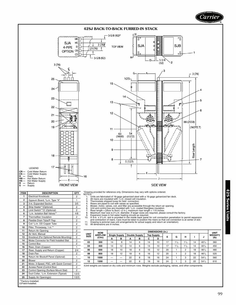
99
42SJ BACK-TO-BACK FURRED-IN STACK
†Unit weights are based on dry coils and minimum rows. Weights exclude packaging, valves, and other components.
UNITSIZE
NOM AIRFLOW
(Cfm)
DIMENSIONS (in.) UNIT WEIGHT†
(lb)Single Supply Double Supply Top Supply
E G H I JA B A B C D
03 300 14 8 14 6 14 10 17 11/2 11/2 14 401/4 360
04 400 14 12 14 6 14 10 17 11/2 11/2 14 401/4 450
06 600 18 10 18 6 16 12 20 1 2 18 461/4 480
08 800 18 12 18 6 16 12 20 1 2 18 461/4 520
10 1000 — — 22 8 18 16 24 1 3 22 541/4 560
12 1200 — — 22 8 18 16 24 1 3 22 541/4 610
*Drawing provided for reference only. Dimensions may vary with options ordered.NOTES:
1. Units are fabricated of 18-gage galvanized steel with a 16-gage galvanized fan deck.2. All risers are insulated with 1/2-in. closed cell insulation.3. Thermostats shipped loose for field connection.4. Risers are piped to coil with valves as specified.5. Blower, motor, valves, coil, and filter are accessible through the return air opening.6. Unit and control box are insulated with 1/2-in. coated fiberglass insulation.7. Riser length = [(floor to floor) +2 in.], maximum riser length = 115 inches.8. Maximum riser size is 21/2-in. diameter. If larger sizes are required, please consult the factory.9. Expansion loops in hot water heating circuits as required.
10. A 9-in. x 21/4-in. slot is provided in the inside back panel for coil connection penetration to permit expansionand contraction of risers. Care must be taken to position the risers so that coil connection is at center of slot.
11. Drawing is pictorial (see unit arrangements for actual supply and return air orientation).12. All dimensions are in inches.
**Factory-Installed.††Field-Installed.
ITEM DESCRIPTION QTY1 Electrical Knockouts 2
2 Gypsum Board, 5/8-in. Type “X” 1
3 3-in. Expanded Section 3/54 Strip Heater**(Optional) 25 Limit Switch**†† (Optional) 26 1/2-in. Isolation Ball Valves** 4/87 Thermafiber Insulation 2
8 Flexible Drain Tube/P-Trap 29 Coil 1/2-in. OD Copper Tube 2
10 Filter, Throwaway, 1-in.** 211 Return Air Opening 212 Air Vent, Manual 213 Knockout (For Optional Remote Mounting) 214 Molex Connector for Field Installed Stat 215 Control Box 216 Riser, Drain (Copper) 117 Riser, Supply and Return (Copper) 2/418 Drain Pan 219 Return Air Blockoff Panel (Optional) 1
20 Blower 221 Motor, 3-Speed, PSC, with Quick Connect 222 Access Panel (Control Box) 223 Control Opening (Surface Mount Stat) 224 Duct Collar, 1/2-in. Extension (Typical) 1/2/3
25 Supply Air Opening(s) 1/2/3
LEGEND
CR — Cold Water ReturnCS — Cold Water SupplyD — DrainHR — Hot Water ReturnHS — Hot Water SupplyR — ReturnS — Supply
A42-4127
42
S S
eries Units

100
Base unit dimensions (cont)
*Drawing provided for reference only. Dimensions may vary with options ordered.NOTES:
1. Units are fabricated of 18-gage galvanized steel with a 16-gage galvanized fan deck.2. All risers are insulated with 1/2-in. closed cell insulation.3. Thermostats shipped loose for field connection.4. Risers are piped to coil with valves as specified.5. Blower, motor, valves, coil, and filter are accessible through the return air opening.6. Unit and control box are insulated with 1/2-in. coated fiberglass insulation.7. Riser length = [(floor to floor) +2 in.], maximum riser length = 115 inches.8. Maximum riser size is 21/2-in. diameter. If larger sizes are required, please consult the factory.9. Expansion loops in hot water heating circuits as required.
10. A 9-in. x 21/4-in. slot is provided in the inside back panel for coil connection penetration to permit expansionand contraction of risers. Care must be taken to position the risers so that coil connection is at center of slot.
11. Drawing is pictorial (see unit arrangements for actual supply and return air orientation).12. All dimensions are in inches.
42SGM FURRED-IN MASTER STACK
†Unit weights are based on dry coils and minimum rows. Weights exclude packaging, valves, and other components.
UNITSIZE
NOM AIRFLOW
(Cfm)
DIMENSIONS (in.) UNIT WEIGHT†
(lb)Single Supply Double Supply Top Supply
E G H IA B A B C D
03 300 14 8 14 6 14 10 17 11/2 11/2 14 180
04 400 14 12 14 6 14 10 17 11/2 11/2 14 225
06 600 18 10 18 6 16 12 20 1 2 18 240
08 800 18 12 18 6 16 12 20 1 2 18 260
10 1000 — — 22 8 18 16 24 1 3 22 280
12 1200 — — 22 8 18 16 24 1 3 22 305
A42-4128
**Factory-Installed.††Field-Installed.
ITEM DESCRIPTION QTY1 Electrical Knockouts 1
2 3-in. Expanded Section 3/53 Strip Heater** (Optional) 14 Limit Switch**†† (Optional) 15 1/2-in. Isolation Ball Valves** 2/46 Flexible Drain Tube/P-Trap 17 Coil 1/2-in. OD Copper Tube 1
8 Filter, Throwaway, 1-in.** 19 Return Air Opening 1
10 Air Vent, Manual 111 Knockout (For Optional Remote Mounting) 212 Molex Connector for Field-Installed Thermostat 113 Control Box 114 Riser, Supply and Return (Copper) 2/415 Riser, Drain (Copper) 116 Drain Pan 117 Return Air Blockoff Panel (Optional) 1
18 Blower 119 Motor, 3-Speed, PSC, with Quick Connect 120 Access Panel (Control Box) 121 Control Opening (Surface Mount Thermostat) 122 Duct Collar, 1/2-in. Extension (Typical) 1/2/3
23 Supply Air Opening(s) 1/2/3
LEGEND
CR — Cold Water ReturnCS — Cold Water SupplyD — DrainHR — Hot Water ReturnHS — Hot Water SupplyR — ReturnS — Supply
42
S S
erie
s U
nits

101
42
S S
eries Units
42
S S
eries Units
*Drawing provided for reference only. Dimensions may vary with options ordered.NOTES:
1. Units are fabricated of 18-gage galvanized steel with a 16-gage galvanized fan deck.2. All risers are insulated with 1/2-in. closed cell insulation.3. Thermostats shipped loose for field connection.4. Risers are piped to coil with valves as specified.5. Blower, motor, valves, coil, and filter are accessible through the return air opening.6. Unit and control box are insulated with 1/2-in. coated fiberglass insulation.7. Riser length = [(floor to floor) +2 in.], maximum riser length = 115 inches.8. Maximum riser size is 21/2-in. diameter. If larger sizes are required, please consult the factory.9. Expansion loops in hot water heating circuits as required.
10. A 9-in. x 21/4-in. slot is provided in the inside back panel for coil connection penetration to permit expansionand contraction of risers. Care must be taken to position the risers so that coil connection is at center of slot.
11. Drawing is pictorial (see unit arrangements for actual supply and return air orientation).12. All dimensions are in inches.
42SGS FURRED-IN SLAVE STACK
†Unit weights are based on dry coils and minimum rows. Weights exclude packaging, valves, and other components.
UNITSIZE
NOM AIRFLOW
(Cfm)
DIMENSIONS (in.) UNIT WEIGHT†
(lb)Single Supply Double Supply Top Supply
E G H IA B A B C D
03 300 14 8 14 6 14 10 17 11/2 11/2 14 162
04 400 14 12 14 6 14 10 17 11/2 11/2 14 203
06 600 18 10 18 6 16 12 20 1 2 18 216
08 800 18 12 18 6 16 12 20 1 2 18 234
10 1000 — — 22 8 18 16 24 1 3 22 252
12 1200 — — 22 8 18 16 24 1 3 22 275
A42-4129
**Factory-Installed.††Field-Installed.
ITEM DESCRIPTION QTY1 Electrical Knockouts 1
2 Strip Heater** (Optional) 13 Limit Switch**†† (Optional) 14 1/2-in. Isolation Ball Valves** 2/45 Coil Stub Outs 2/46 Shipping Brace 2/47 Flexible Drain Tube/P-Trap 18 Coil 1/2-in. OD Copper Tube 1
9 Filter, Throwaway, 1-in.** 110 Return Air Opening 111 Air Vent, Manual 112 Knockout (For Optional Remote Mounting) 213 Molex Connector for Field-Installed Stat 114 Control Box 115 Drain Pan 116 Return Air Blockoff Panel (Optional) 117 Blower 118 Motor, 3-Speed, PSC, with Quick Connect 119 Access Panel (Control Box) 120 Control Opening (Surface Mount Thermostat) 121 Duct Collar, 1/2-in. Extension (Typical) 1/2/3
22 Supply Air Opening(s) 1/2/3
LEGEND
CR — Cold Water ReturnCS — Cold Water SupplyD — DrainHR — Hot Water ReturnHS — Hot Water SupplyR — ReturnS — Supply

102
Accessory dimensions4
2S
Ser
ies
Uni
ts
GRILLE LOCATIONS
UNIT FIG. GRILLE ARRANGEMENTS
42SG ASupply Up to 3 grilles located on any of
3 sides shown.
Return One grille located on any of 3 sides shown.
42SH BSupply Up to 3 grilles located on any of
3 sides shown.Return One grille located opposite risers.
42SJ CSupply Up to 3 grilles located on any of
3 sides shown (per section).
Return One grille located on any of 3 sides shown (per section).
PANEL NO. 1 PANEL NO. 2
SHORT FRAME — SURFACE MOUNTED GRILLE
LONG FRAME — SURFACE MOUNTED GRILLE
PANEL NO. 3
SHORT FRAME — SURFACE MOUNTED GRILLE
a42-4002

103
42
S S
eries Units
PANEL NO. 5
LONG FRAME — FLUSH MOUNTED GRILLE
PANEL NO. 4
SHORT FRAME — FLUSH MOUNTED GRILLE
PANEL NO. 6
LONG FRAME — FLUSH MOUNTED GRILLE
A42-4131
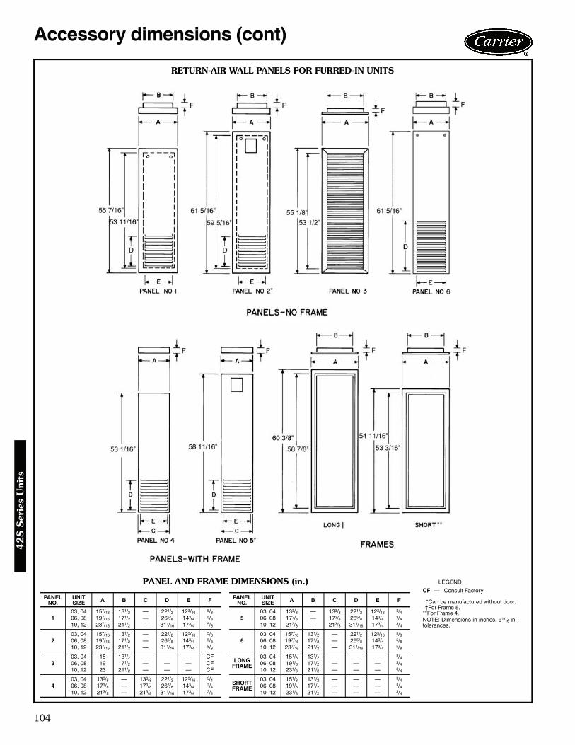
104
Accessory dimensions (cont)4
2S
Ser
ies
Uni
ts
RETURN-AIR WALL PANELS FOR FURRED-IN UNITS
PANEL AND FRAME DIMENSIONS (in.)
PANELNO.
UNITSIZE A B C D E F PANEL
NO.UNITSIZE A B C D E F
103, 04 157/16 131/2 — 221/2 123/16 5/8
503, 04 133/8 — 133/8 221/2 123/16 3/4
06, 08 197/16 171/2 — 265/8 143/4 5/8 06, 08 173/8 — 173/8 265/8 143/4 3/410, 12 237/16 211/2 — 311/16 173/4 5/8 10, 12 213/8 — 213/8 311/16 173/4 3/4
203, 04 157/16 131/2 — 221/2 123/16 5/8
603, 04 157/16 131/2 — 221/2 123/16 5/8
06, 08 197/16 171/2 — 265/8 143/4 5/8 06, 08 197/16 171/2 — 265/8 143/4 5/810, 12 237/16 211/2 — 311/16 173/4 5/8 10, 12 237/16 211/2 — 311/16 173/4 5/8
303, 04 15 131/2 — — — CF
LONGFRAME
03, 04 151/8 131/2 — — — 3/406, 08 19 171/2 — — — CF 06, 08 191/8 171/2 — — — 3/410, 12 23 211/2 — — — CF 10, 12 231/8 211/2 — — — 3/4
403, 04 133/8 — 133/8 221/2 123/16 3/4 SHORT
FRAME
03, 04 151/8 131/2 — — — 3/406, 08 173/8 — 173/8 265/8 143/4 3/4 06, 08 191/8 171/2 — — — 3/410, 12 213/8 — 213/8 311/16 173/4 3/4 10, 12 231/8 211/2 — — — 3/4
LEGEND
*Can be manufactured without door.†For Frame 5.
**For Frame 4.NOTE: Dimensions in inches. ±1/16 in.tolerances.
CF — Consult Factory
a42-4130

105
AIR DELIVERY
AIR DELIVERY WITH HIGH-STATIC FAN
LEGENDESP — External Static Pressure (in. wg)
NOTES:1. Size 03 unit available with high-static motor in 208/230 or
277-1-60.2. Sizes 04-12 units available with high-static motor in 115/208/230
or 277-1-60.
UNIT SIZE COILCFM AT 0.0 ESP FOR FAN SPEED HIGH SPEED CFM AT ESP INDICATEDLow Med High 0.05 0.10 0.15 0.20 0.25
42SG,SH,SJ
03
3 Row
260 300 440 410 380 340 300 24004 300 410 510 480 450 420 380 34006 490 570 710 670 630 590 540 48008 580 650 840 800 760 710 670 61010 640 960 1130 1100 1070 1040 1000 97012 750 940 1260 1230 1200 1160 1130 109003
4 Row
250 290 420 390 350 320 280 22004 280 400 490 470 430 400 360 32006 480 560 590 560 520 480 430 38008 460 590 800 760 720 670 620 56010 630 940 1090 1060 1040 1010 980 95012 740 920 1250 1220 1180 1150 1110 1070
UNIT SIZE COILHIGH SPEED CFM AT ESP INDICATED
0.2 0.25 0.3 0.4 0.5
42SG,SH,SJ
033 Row 505 485 465 420 3704 Row 485 465 445 400 3505 Row 465 445 425 380 330
043 Row 530 510 485 440 4004 Row 510 490 465 420 3805 Row 490 470 445 400 360
063 Row 860 820 790 720 6604 Row 840 800 770 700 6405 Row 820 780 750 680 620
083 Row 1020 985 940 845 7804 Row 1000 965 920 825 7605 Row 980 945 900 805 740
103 Row 1265 1235 1205 1140 10754 Row 1245 1215 1185 1120 10555 Row 1225 1195 1165 1100 1035
123 Row 1320 1300 1290 1235 11604 Row 1300 1280 1270 1215 11405 Row 1280 1260 1250 1195 1120
Performance data4
2S
Series U
nits

106
42S COOLING CAPACITY (GPM) 3-ROW COIL
42S COOLING CAPACITY (GPM) 4-ROW COIL
LEGEND
NOTE: All capacities are given in thousands of Btuh (MBtuh).
UNITSIZE GPM
EAT 75 F DB/63 F WB EAT 80 F DB/67 F WB EAT 85 F DB/71 F WB40 F EWT 45 F EWT 50 F EWT 40 F EWT 45 F EWT 50 F EWT 40 F EWT 45 F EWT 50 F EWT
ΔT TCb SCb ΔT TCb SCb ΔT TCb SCb ΔT TCb SCb ΔT TCb SCb ΔT TCb SCb ΔT TCb SCb ΔT TCb TCb ΔT TCb SCb
031 16.4 8.2 6.7 13.5 6.8 6.0 10.9 5.4 5.2 19.5 9.8 7.4 16.5 8.2 6.7 13.6 6.8 6.0 22.9 11.4 8.0 19.7 9.9 7.4 16.6 8.3 6.7
1.5 13.0 9.7 7.4 10.5 7.9 6.6 8.2 6.2 5.8 15.7 11.8 8.3 13.1 9.9 7.4 10.6 7.9 6.6 18.7 14.0 9.0 16.0 12.0 8.2 13.2 9.9 7.42 10.8 10.8 7.9 8.6 8.6 6.9 6.6 6.6 6.0 13.1 13.1 8.8 10.8 10.8 7.8 8.6 8.6 6.9 15.5 15.5 9.6 13.2 13.2 8.7 10.9 10.9 7.8
2.5 9.1 11.4 8.2 7.3 9.1 7.2 5.5 6.9 6.2 11.1 13.9 9.2 9.2 11.6 8.2 7.3 9.2 7.2 13.3 16.6 10.1 11.3 14.2 9.1 9.3 11.7 8.1
041 18.0 9.0 7.8 15.1 7.5 7.0 12.3 6.2 6.0 21.3 10.6 8.6 18.2 9.1 7.8 15.2 7.6 7.0 24.8 12.4 9.3 21.5 10.7 8.6 18.3 9.1 7.9
1.5 14.5 10.9 8.8 11.9 8.9 7.8 9.5 7.1 6.8 17.4 13.1 9.7 14.6 11.0 8.8 11.9 8.9 7.9 20.5 15.4 10.5 17.6 13.2 9.7 14.6 11.0 8.82 12.2 12.2 9.4 9.8 9.8 8.3 7.6 7.6 7.2 14.6 14.6 10.4 12.2 12.2 9.3 9.8 9.8 8.3 17.4 17.4 11.3 14.8 14.8 10.3 12.2 12.2 9.3
2.5 10.4 13.0 9.8 8.4 10.4 8.6 6.4 8.0 7.5 12.7 15.8 10.9 10.5 13.1 9.7 8.3 10.4 8.6 15.1 18.8 11.9 12.8 16.0 10.8 10.6 13.2 9.7
06
1 22.7 11.3 10.1 19.6 9.8 9.0 15.8 7.9 7.9 26.3 13.1 11.1 23.1 11.6 10.2 20.0 10.0 9.1 30.0 15.0 12.1 26.7 13.4 11.2 23.6 11.8 10.31.5 18.6 13.9 11.8 15.9 11.9 10.7 13.3 10.0 9.3 21.7 16.3 13.0 18.9 14.2 11.9 16.2 12.2 10.8 25.1 18.8 14.0 22.1 16.6 13.1 19.2 14.4 12.02 15.8 15.8 12.9 13.3 13.3 11.6 11.0 11.0 10.2 18.7 18.7 14.1 16.0 16.0 12.9 13.5 13.5 11.7 21.9 21.9 15.3 19.0 19.0 14.2 16.3 16.3 13.13 12.3 18.5 14.2 10.2 15.2 12.7 8.1 12.2 11.2 14.9 22.3 15.7 12.5 18.8 14.2 10.2 15.4 12.8 17.6 26.3 17.1 15.1 22.7 15.6 12.7 19.0 14.24 10.1 20.3 15.0 8.2 16.4 13.2 6.4 12.8 11.6 12.3 24.6 16.7 10.2 20.5 14.9 8.2 16.5 13.3 14.5 29.1 18.2 12.4 24.9 16.5 10.3 20.7 14.9
08
1 24.0 12.0 11.0 20.7 10.3 9.7 16.7 8.4 8.4 27.8 13.9 12.3 24.5 12.2 11.1 20.4 10.2 10.2 31.7 15.8 13.4 28.3 14.2 12.4 25.0 12.5 11.31.5 20.2 15.1 13.4 17.3 13.0 11.9 14.0 10.5 10.5 23.5 17.6 14.8 20.5 15.4 13.5 17.7 13.3 12.1 27.0 20.2 16.0 23.9 17.9 14.9 20.9 15.7 13.72 17.3 17.3 14.8 14.7 14.7 13.3 12.3 12.3 11.5 20.4 20.4 16.3 17.6 17.6 15.0 15.0 15.0 13.5 23.6 23.6 17.6 20.7 20.7 16.4 17.9 17.9 15.13 13.7 20.5 16.6 11.4 17.1 14.9 9.3 13.9 13.0 16.4 24.6 18.2 13.9 20.8 16.7 11.5 17.2 15.0 19.3 28.9 19.8 16.6 25.0 18.3 14.0 21.0 16.74 11.4 22.8 17.6 9.2 18.5 15.7 7.3 14.7 13.7 13.7 27.3 19.4 11.4 22.8 17.6 9.3 18.5 15.7 16.1 32.3 21.2 13.8 27.6 19.3 11.5 23.0 17.6
10
1.5 22.6 16.9 15.2 19.5 14.7 13.5 15.4 11.5 11.5 26.2 19.6 16.9 23.1 17.4 15.4 20.1 15.0 13.7 29.9 22.4 18.4 26.8 20.1 17.1 23.7 17.8 15.62 19.9 19.9 17.4 17.2 17.2 15.5 13.5 13.5 13.5 23.1 23.1 19.2 20.3 20.3 17.6 17.6 17.6 15.7 26.6 26.6 20.8 23.7 23.7 19.4 20.8 20.8 17.83 16.0 23.9 19.9 13.6 20.4 18.0 11.3 17.0 15.7 18.9 28.3 21.9 16.3 24.4 20.1 13.8 20.8 18.2 22.0 32.9 23.7 19.2 28.8 22.0 16.6 24.9 20.34 13.5 26.9 21.5 11.2 22.4 19.3 9.2 18.4 16.9 16.1 32.2 23.6 13.7 27.4 21.6 11.4 22.8 19.5 18.9 37.8 25.7 16.4 32.8 23.7 13.9 27.8 21.76 10.3 30.9 23.4 8.4 25.1 20.7 6.6 19.8 18.1 12.5 37.4 25.9 10.4 31.2 23.3 8.4 25.2 20.8 14.7 44.2 28.2 12.6 37.9 25.7 10.5 31.5 23.3
12
1.5 23.3 17.4 16.0 19.1 14.3 14.3 15.8 11.9 11.9 27.0 20.3 17.9 23.3 17.9 16.2 19.3 14.5 14.5 30.8 23.1 19.6 27.7 20.7 18.1 24.4 18.3 16.42 20.7 20.7 18.5 17.9 17.9 16.5 14.1 14.1 14.1 24.1 24.1 20.6 21.2 21.2 18.8 18.4 18.4 16.7 27.6 27.6 22.4 24.7 24.7 20.8 21.8 21.8 19.03 16.9 25.3 21.7 14.4 21.6 19.5 12.0 18.1 16.8 19.8 29.7 23.9 17.2 25.8 21.9 14.7 22.1 19.7 23.0 34.5 25.8 20.2 30.3 24.1 17.6 26.4 22.24 14.3 28.6 23.5 12.0 24.0 21.2 9.9 19.8 18.4 17.0 34.0 25.9 14.5 29.1 23.7 12.2 24.4 21.4 19.9 39.8 28.1 17.3 34.6 26.0 14.8 29.6 23.96 11.0 33.1 25.7 9.0 27.0 22.9 7.2 21.6 20.0 13.3 39.8 28.4 11.1 33.3 25.7 9.0 27.1 23.1 15.7 47.0 30.9 13.4 40.3 28.3 11.2 33.6 25.8
UNITSIZE GPM
EAT 75 F DB/63 F WB EAT 80 F DB/67 F WB EAT 85 F DB/71 F WB40 F EWT 45 F EWT 50 F EWT 40 F EWT 45 F EWT 50 F EWT 40 F EWT 45 F EWT 50 F EWT
ΔT TCb SCb ΔT TCb SCb ΔT TCb SCb ΔT TCb SCb ΔT TCb SCb ΔT TCb SCb ΔT TCb SCb ΔT TCb TCb ΔT TCb SCb
03
1 18.2 9.1 7.2 15.6 7.8 6.6 13.2 6.6 5.8 21.3 10.7 7.9 18.5 9.2 7.3 15.9 7.9 6.6 24.6 12.3 8.5 21.6 10.8 7.9 18.8 9.4 7.31.5 14.3 10.7 8.0 11.9 8.9 7.2 9.8 7.3 6.4 17.1 12.8 8.8 14.5 10.9 8.0 12.1 9.1 7.2 20.0 15.0 9.6 17.4 13.0 8.8 14.7 11.1 8.02 11.8 11.8 8.5 9.7 9.1 7.6 7.7 7.7 6.7 14.3 14.3 9.5 12.1 12.1 8.5 9.9 9.9 7.6 16.9 16.9 10.4 14.6 14.6 9.4 12.3 12.3 8.5
2.5 10.1 12.6 8.9 8.3 10.3 7.9 6.5 8.1 6.8 12.3 15.3 9.9 10.3 12.9 8.9 8.4 10.5 7.9 14.6 18.2 10.9 12.6 15.8 9.9 10.6 13.2 8.83 8.8 13.2 9.2 7.2 10.8 8.1 5.6 8.3 7.0 10.7 16.1 10.3 9.1 13.6 9.2 7.3 10.9 8.0 12.8 19.2 11.4 11.1 16.6 10.2 9.2 13.9 9.1
04
1 20.2 10.1 8.5 17.4 8.7 7.6 14.8 7.4 6.7 23.4 11.7 9.2 20.5 10.3 8.5 17.8 8.9 7.7 26.9 13.4 10.0 23.8 11.9 9.3 21.0 10.5 8.61.5 16.1 12.0 9.5 13.6 10.2 8.6 11.3 8.5 7.6 19.0 14.3 10.4 16.3 12.2 9.6 13.8 10.4 8.7 22.1 16.6 11.3 19.3 14.5 10.4 16.6 12.4 9.62 13.5 13.5 10.2 11.2 11.2 9.2 9.1 9.1 8.1 16.1 16.1 11.3 13.7 13.7 10.2 11.3 11.3 9.2 19.0 19.0 12.2 16.4 16.4 11.2 13.9 13.9 10.2
2.5 11.7 14.6 10.7 9.6 12.0 9.5 7.6 9.5 8.4 14.1 17.6 11.9 11.9 14.9 10.7 9.7 12.1 9.6 16.6 20.8 13.0 14.4 18.0 11.8 12.1 15.1 10.73 10.3 15.4 11.1 8.4 12.6 9.8 6.6 9.9 8.6 12.5 18.7 12.4 10.5 15.7 11.1 8.5 12.8 9.9 14.8 22.2 13.6 12.8 19.2 12.3 10.7 16.0 11.1
06
1 26.0 13.0 11.1 22.7 11.4 10.0 19.4 9.7 8.7 29.9 15.0 12.2 26.5 13.3 11.2 23.3 11.6 10.1 33.9 17.0 13.1 30.5 15.2 12.3 27.2 13.6 11.32 18.2 18.2 14.3 15.5 15.5 13.0 13.0 13.0 11.5 21.5 21.5 15.7 18.5 18.5 14.4 15.8 15.8 13.1 25.0 25.0 16.9 21.8 21.8 15.7 18.8 18.8 14.43 14.2 21.3 15.8 11.8 17.6 14.1 9.5 14.2 12.5 17.0 25.6 17.5 14.4 21.7 15.8 11.9 17.8 14.2 20.1 30.1 19.1 17.4 26.1 17.4 14.6 21.9 15.84 11.7 23.3 16.8 9.5 18.9 14.8 7.4 14.9 12.9 14.0 28.1 18.6 11.8 23.6 16.6 9.5 19.1 14.8 16.6 33.2 20.3 14.3 28.6 18.4 11.9 23.8 16.55 9.8 24.5 17.3 8.0 19.9 15.2 6.1 15.4 13.2 11.9 29.8 19.3 10.0 24.9 17.2 8.0 20.0 15.2 14.2 35.4 21.2 12.2 30.4 19.1 10.1 25.3 17.1
08
1 27.5 13.7 12.2 23.8 11.9 10.8 18.9 9.4 9.4 31.7 15.8 13.5 28.0 14.0 12.3 24.3 12.2 10.9 35.9 17.9 14.6 32.3 16.1 13.6 28.6 14.3 12.42 20.2 20.2 16.7 17.3 17.3 15.1 14.6 14.6 13.2 23.6 23.6 18.3 20.5 20.5 16.8 17.7 17.7 15.2 27.2 27.2 19.7 24.0 24.0 18.3 20.9 20.9 16.93 16.0 23.9 18.7 13.4 20.0 16.8 11.0 16.5 14.8 19.0 28.5 20.6 16.2 24.3 18.8 13.5 20.3 16.9 22.2 33.3 22.3 19.3 28.9 20.5 16.3 24.5 18.84 13.2 26.5 20.0 10.8 21.6 17.7 8.7 17.3 15.6 15.8 31.7 22.0 13.3 26.6 19.8 10.9 21.8 17.8 18.7 37.3 23.9 16.0 32.1 21.8 13.4 26.9 19.85 11.3 28.1 20.7 9.2 22.9 18.3 7.2 18.0 16.0 13.6 34.0 23.0 11.4 28.5 20.6 9.2 23.0 18.4 16.1 40.3 25.1 13.8 34.5 22.8 11.5 28.7 20.5
10
2 22.3 22.3 19.0 19.5 19.5 17.1 14.7 14.7 14.7 25.8 25.8 20.9 22.9 22.9 19.2 20.1 20.1 17.4 29.3 29.3 22.6 26.4 26.4 21.1 23.6 23.6 19.53 18.0 27.0 22.0 15.6 23.3 19.9 13.2 19.8 17.6 21.1 31.6 24.0 18.4 27.7 22.2 16.0 24.0 20.2 24.4 36.5 25.9 21.6 32.3 24.2 18.9 28.4 22.44 15.2 30.4 23.7 12.9 25.7 21.5 10.8 21.5 19.0 18.0 36.1 26.0 15.5 31.0 23.9 13.2 26.3 21.7 21.0 42.1 28.2 18.4 36.8 26.1 15.8 31.7 24.06 11.7 35.1 26.0 9.7 29.0 23.2 7.8 23.3 20.5 14.1 42.3 28.8 11.9 35.8 26.0 9.8 29.4 23.3 16.7 50.0 31.4 14.4 43.3 28.7 12.1 36.4 26.08 9.5 38.1 27.4 7.7 31.0 24.1 6.1 24.2 21.1 11.5 46.2 30.5 9.7 38.7 27.2 7.8 31.2 24.1 13.7 54.7 33.3 11.7 47.0 30.1 9.8 39.2 27.1
12
2 23.3 23.3 20.3 20.3 20.3 18.1 15.4 15.4 15.4 26.9 26.9 22.5 23.9 23.9 20.6 20.9 20.9 18.4 30.6 30.6 24.4 27.7 27.7 22.8 24.7 24.7 20.93 19.2 28.7 24.1 16.6 24.9 21.7 14.1 21.1 18.9 22.3 33.5 26.4 19.6 29.5 24.3 17.1 25.6 22.0 25.7 38.5 28.5 22.8 34.2 26.6 20.2 30.2 24.64 16.2 32.5 26.2 13.9 27.7 23.8 11.7 23.3 20.9 19.2 38.3 28.8 16.6 33.2 26.4 14.2 28.4 24.0 22.7 44.5 31.1 19.6 39.1 28.9 17.0 33.9 26.76 12.6 37.9 28.9 10.5 31.5 25.9 8.5 25.6 22.9 15.1 45.4 31.9 12.9 38.6 29.0 10.6 31.9 26.1 17.8 53.5 34.7 15.5 46.4 31.9 13.0 39.1 29.18 10.4 41.4 30.6 8.4 33.7 27.1 6.7 26.7 23.7 12.5 50.0 33.9 10.5 41.9 30.4 8.5 34.0 27.1 14.8 59.1 36.9 12.7 50.7 33.6 10.6 42.3 30.3
ΔT — Temperature Change GPM — Gallons per MinuteDB — Dry Bulb SCb — Base Sensible CapacityEAT — Entering Air Temperature TCb — Base Total CapacityEWT — Entering Water Temperature WB — Wet Bulb
Performance data (cont)4
2S
Ser
ies
Uni
ts
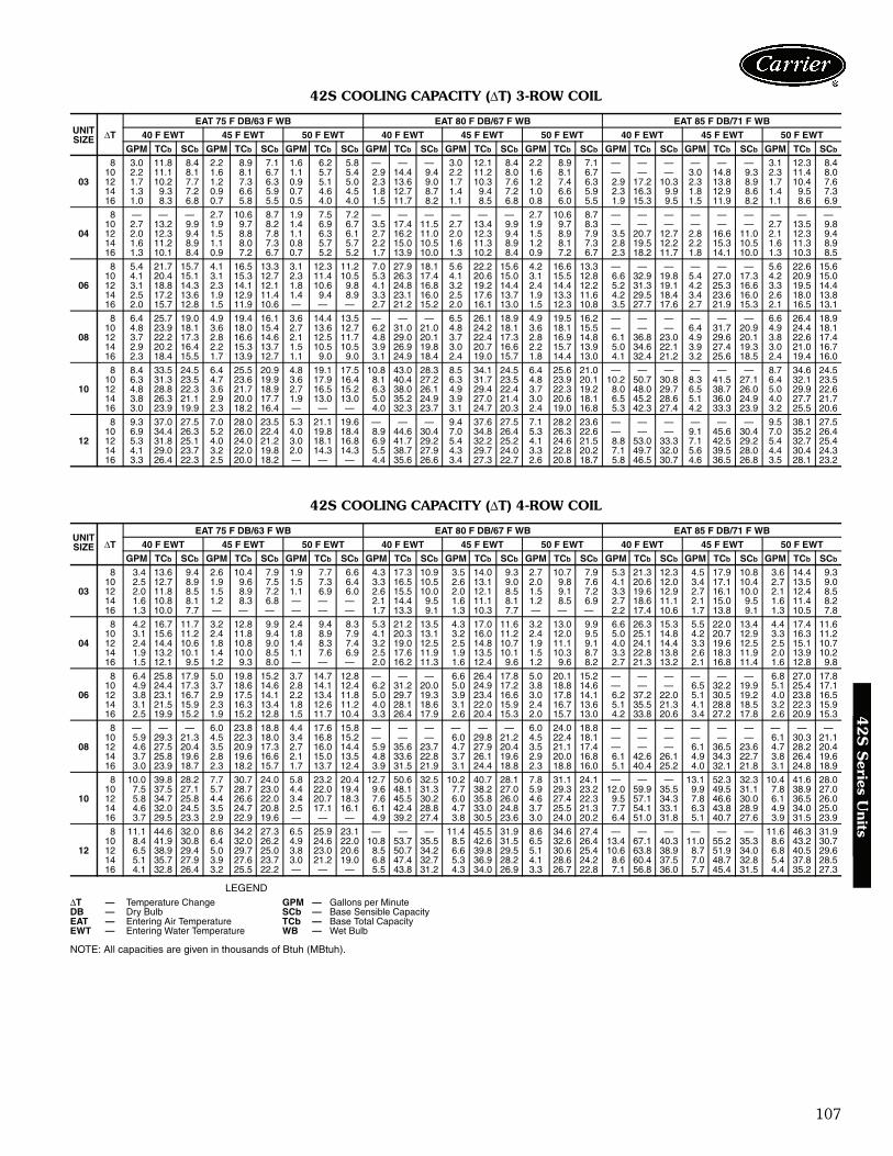
107
42S COOLING CAPACITY (ΔT) 3-ROW COIL
42S COOLING CAPACITY (ΔT) 4-ROW COIL
LEGEND
NOTE: All capacities are given in thousands of Btuh (MBtuh).
UNITSIZE ΔT
EAT 75 F DB/63 F WB EAT 80 F DB/67 F WB EAT 85 F DB/71 F WB40 F EWT 45 F EWT 50 F EWT 40 F EWT 45 F EWT 50 F EWT 40 F EWT 45 F EWT 50 F EWT
GPM TCb SCb GPM TCb SCb GPM TCb SCb GPM TCb SCb GPM TCb SCb GPM TCb SCb GPM TCb SCb GPM TCb SCb GPM TCb SCb
03
8 3.0 11.8 8.4 2.2 8.9 7.1 1.6 6.2 5.8 — — — 3.0 12.1 8.4 2.2 8.9 7.1 — — — — — — 3.1 12.3 8.410 2.2 11.1 8.1 1.6 8.1 6.7 1.1 5.7 5.4 2.9 14.4 9.4 2.2 11.2 8.0 1.6 8.1 6.7 — — — 3.0 14.8 9.3 2.3 11.4 8.012 1.7 10.2 7.7 1.2 7.3 6.3 0.9 5.1 5.0 2.3 13.6 9.0 1.7 10.3 7.6 1.2 7.4 6.3 2.9 17.2 10.3 2.3 13.8 8.9 1.7 10.4 7.614 1.3 9.3 7.2 0.9 6.6 5.9 0.7 4.6 4.5 1.8 12.7 8.7 1.4 9.4 7.2 1.0 6.6 5.9 2.3 16.3 9.9 1.8 12.9 8.6 1.4 9.5 7.316 1.0 8.3 6.8 0.7 5.8 5.5 0.5 4.0 4.0 1.5 11.7 8.2 1.1 8.5 6.8 0.8 6.0 5.5 1.9 15.3 9.5 1.5 11.9 8.2 1.1 8.6 6.9
04
8 — — — 2.7 10.6 8.7 1.9 7.5 7.2 — — — — — — 2.7 10.6 8.7 — — — — — — — — —10 2.7 13.2 9.9 1.9 9.7 8.2 1.4 6.9 6.7 3.5 17.4 11.5 2.7 13.4 9.9 1.9 9.7 8.3 — — — — — — 2.7 13.5 9.812 2.0 12.3 9.4 1.5 8.8 7.8 1.1 6.3 6.1 2.7 16.2 11.0 2.0 12.3 9.4 1.5 8.9 7.9 3.5 20.7 12.7 2.8 16.6 11.0 2.1 12.3 9.414 1.6 11.2 8.9 1.1 8.0 7.3 0.8 5.7 5.7 2.2 15.0 10.5 1.6 11.3 8.9 1.2 8.1 7.3 2.8 19.5 12.2 2.2 15.3 10.5 1.6 11.3 8.916 1.3 10.1 8.4 0.9 7.2 6.7 0.7 5.2 5.2 1.7 13.9 10.0 1.3 10.2 8.4 0.9 7.2 6.7 2.3 18.2 11.7 1.8 14.1 10.0 1.3 10.3 8.5
06
8 5.4 21.7 15.7 4.1 16.5 13.3 3.1 12.3 11.2 7.0 27.9 18.1 5.6 22.2 15.6 4.2 16.6 13.3 — — — — — — 5.6 22.6 15.610 4.1 20.4 15.1 3.1 15.3 12.7 2.3 11.4 10.5 5.3 26.3 17.4 4.1 20.6 15.0 3.1 15.5 12.8 6.6 32.9 19.8 5.4 27.0 17.3 4.2 20.9 15.012 3.1 18.8 14.3 2.3 14.1 12.1 1.8 10.6 9.8 4.1 24.8 16.8 3.2 19.2 14.4 2.4 14.4 12.2 5.2 31.3 19.1 4.2 25.3 16.6 3.3 19.5 14.414 2.5 17.2 13.6 1.9 12.9 11.4 1.4 9.4 8.9 3.3 23.1 16.0 2.5 17.6 13.7 1.9 13.3 11.6 4.2 29.5 18.4 3.4 23.6 16.0 2.6 18.0 13.816 2.0 15.7 12.8 1.5 11.9 10.6 — — — 2.7 21.2 15.2 2.0 16.1 13.0 1.5 12.3 10.8 3.5 27.7 17.6 2.7 21.9 15.3 2.1 16.5 13.1
08
8 6.4 25.7 19.0 4.9 19.4 16.1 3.6 14.4 13.5 — — — 6.5 26.1 18.9 4.9 19.5 16.2 — — — — — — 6.6 26.4 18.910 4.8 23.9 18.1 3.6 18.0 15.4 2.7 13.6 12.7 6.2 31.0 21.0 4.8 24.2 18.1 3.6 18.1 15.5 — — — 6.4 31.7 20.9 4.9 24.4 18.112 3.7 22.2 17.3 2.8 16.6 14.6 2.1 12.5 11.7 4.8 29.0 20.1 3.7 22.4 17.3 2.8 16.9 14.8 6.1 36.8 23.0 4.9 29.6 20.1 3.8 22.6 17.414 2.9 20.2 16.4 2.2 15.3 13.7 1.5 10.5 10.5 3.9 26.9 19.8 3.0 20.7 16.6 2.2 15.7 13.9 5.0 34.6 22.1 3.9 27.4 19.3 3.0 21.0 16.716 2.3 18.4 15.5 1.7 13.9 12.7 1.1 9.0 9.0 3.1 24.9 18.4 2.4 19.0 15.7 1.8 14.4 13.0 4.1 32.4 21.2 3.2 25.6 18.5 2.4 19.4 16.0
10
8 8.4 33.5 24.5 6.4 25.5 20.9 4.8 19.1 17.5 10.8 43.0 28.3 8.5 34.1 24.5 6.4 25.6 21.0 — — — — — — 8.7 34.6 24.510 6.3 31.3 23.5 4.7 23.6 19.9 3.6 17.9 16.4 8.1 40.4 27.2 6.3 31.7 23.5 4.8 23.9 20.1 10.2 50.7 30.8 8.3 41.5 27.1 6.4 32.1 23.512 4.8 28.8 22.3 3.6 21.7 18.9 2.7 16.5 15.2 6.3 38.0 26.1 4.9 29.4 22.4 3.7 22.3 19.2 8.0 48.0 29.7 6.5 38.7 26.0 5.0 29.9 22.614 3.8 26.3 21.1 2.9 20.0 17.7 1.9 13.0 13.0 5.0 35.2 24.9 3.9 27.0 21.4 3.0 20.6 18.1 6.5 45.2 28.6 5.1 36.0 24.9 4.0 27.7 21.716 3.0 23.9 19.9 2.3 18.2 16.4 — — — 4.0 32.3 23.7 3.1 24.7 20.3 2.4 19.0 16.8 5.3 42.3 27.4 4.2 33.3 23.9 3.2 25.5 20.6
12
8 9.3 37.0 27.5 7.0 28.0 23.5 5.3 21.1 19.6 — — — 9.4 37.6 27.5 7.1 28.2 23.6 — — — — — — 9.5 38.1 27.510 6.9 34.4 26.3 5.2 26.0 22.4 4.0 19.8 18.4 8.9 44.6 30.4 7.0 34.8 26.4 5.3 26.3 22.6 — — — 9.1 45.6 30.4 7.0 35.2 26.412 5.3 31.8 25.1 4.0 24.0 21.2 3.0 18.1 16.8 6.9 41.7 29.2 5.4 32.2 25.2 4.1 24.6 21.5 8.8 53.0 33.3 7.1 42.5 29.2 5.4 32.7 25.414 4.1 29.0 23.7 3.2 22.0 19.8 2.0 14.3 14.3 5.5 38.7 27.9 4.3 29.7 24.0 3.3 22.8 20.2 7.1 49.7 32.0 5.6 39.5 28.0 4.4 30.4 24.316 3.3 26.4 22.3 2.5 20.0 18.2 — — — 4.4 35.6 26.6 3.4 27.3 22.7 2.6 20.8 18.7 5.8 46.5 30.7 4.6 36.5 26.8 3.5 28.1 23.2
UNITSIZE ΔT
EAT 75 F DB/63 F WB EAT 80 F DB/67 F WB EAT 85 F DB/71 F WB40 F EWT 45 F EWT 50 F EWT 40 F EWT 45 F EWT 50 F EWT 40 F EWT 45 F EWT 50 F EWT
GPM TCb SCb GPM TCb SCb GPM TCb SCb GPM TCb SCb GPM TCb SCb GPM TCb SCb GPM TCb SCb GPM TCb SCb GPM TCb SCb
03
8 3.4 13.6 9.4 2.6 10.4 7.9 1.9 7.7 6.6 4.3 17.3 10.9 3.5 14.0 9.3 2.7 10.7 7.9 5.3 21.3 12.3 4.5 17.9 10.8 3.6 14.4 9.310 2.5 12.7 8.9 1.9 9.6 7.5 1.5 7.3 6.4 3.3 16.5 10.5 2.6 13.1 9.0 2.0 9.8 7.6 4.1 20.6 12.0 3.4 17.1 10.4 2.7 13.5 9.012 2.0 11.8 8.5 1.5 8.9 7.2 1.1 6.9 6.0 2.6 15.5 10.0 2.0 12.1 8.5 1.5 9.1 7.2 3.3 19.6 12.9 2.7 16.1 10.0 2.1 12.4 8.514 1.6 10.8 8.1 1.2 8.3 6.8 — — — 2.1 14.4 9.5 1.6 11.1 8.1 1.2 8.5 6.9 2.7 18.6 11.1 2.1 15.0 9.5 1.6 11.4 8.216 1.3 10.0 7.7 — — — — — — 1.7 13.3 9.1 1.3 10.3 7.7 — — — 2.2 17.4 10.6 1.7 13.8 9.1 1.3 10.5 7.8
04
8 4.2 16.7 11.7 3.2 12.8 9.9 2.4 9.4 8.3 5.3 21.2 13.5 4.3 17.0 11.6 3.2 13.0 9.9 6.6 26.3 15.3 5.5 22.0 13.4 4.4 17.4 11.610 3.1 15.6 11.2 2.4 11.8 9.4 1.8 8.9 7.9 4.1 20.3 13.1 3.2 16.0 11.2 2.4 12.0 9.5 5.0 25.1 14.8 4.2 20.7 12.9 3.3 16.3 11.212 2.4 14.4 10.6 1.8 10.8 9.0 1.4 8.3 7.4 3.2 19.0 12.5 2.5 14.8 10.7 1.9 11.1 9.1 4.0 24.1 14.4 3.3 19.6 12.5 2.5 15.1 10.714 1.9 13.2 10.1 1.4 10.0 8.5 1.1 7.6 6.9 2.5 17.6 11.9 1.9 13.5 10.1 1.5 10.3 8.7 3.3 22.8 13.8 2.6 18.3 11.9 2.0 13.9 10.216 1.5 12.1 9.5 1.2 9.3 8.0 — — — 2.0 16.2 11.3 1.6 12.4 9.6 1.2 9.6 8.2 2.7 21.3 13.2 2.1 16.8 11.4 1.6 12.8 9.8
06
8 6.4 25.8 17.9 5.0 19.8 15.2 3.7 14.7 12.8 — — — 6.6 26.4 17.8 5.0 20.1 15.2 — — — — — — 6.8 27.0 17.810 4.9 24.4 17.3 3.7 18.6 14.6 2.8 14.1 12.4 6.2 31.2 20.0 5.0 24.9 17.2 3.8 18.8 14.6 — — — 6.5 32.2 19.9 5.1 25.4 17.112 3.8 23.1 16.7 2.9 17.5 14.1 2.2 13.4 11.8 5.0 29.7 19.3 3.9 23.4 16.6 3.0 17.8 14.1 6.2 37.2 22.0 5.1 30.5 19.2 4.0 23.8 16.514 3.1 21.5 15.9 2.3 16.3 13.4 1.8 12.6 11.2 4.0 28.1 18.6 3.1 22.0 15.9 2.4 16.7 13.6 5.1 35.5 21.3 4.1 28.8 18.5 3.2 22.3 15.916 2.5 19.9 15.2 1.9 15.2 12.8 1.5 11.7 10.4 3.3 26.4 17.9 2.6 20.4 15.3 2.0 15.7 13.0 4.2 33.8 20.6 3.4 27.2 17.8 2.6 20.9 15.3
08
8 — — — 6.0 23.8 18.8 4.4 17.6 15.8 — — — — — — 6.0 24.0 18.8 — — — — — — — — —10 5.9 29.3 21.3 4.5 22.3 18.0 3.4 16.8 15.2 — — — 6.0 29.8 21.2 4.5 22.4 18.1 — — — — — — 6.1 30.3 21.112 4.6 27.5 20.4 3.5 20.9 17.3 2.7 16.0 14.4 5.9 35.6 23.7 4.7 27.9 20.4 3.5 21.1 17.4 — — — 6.1 36.5 23.6 4.7 28.2 20.414 3.7 25.8 19.6 2.8 19.6 16.6 2.1 15.0 13.5 4.8 33.6 22.8 3.7 26.1 19.6 2.9 20.0 16.8 6.1 42.6 26.1 4.9 34.3 22.7 3.8 26.4 19.616 3.0 23.9 18.7 2.3 18.2 15.7 1.7 13.7 12.4 3.9 31.5 21.9 3.1 24.4 18.8 2.3 18.8 16.0 5.1 40.4 25.2 4.0 32.1 21.8 3.1 24.8 18.9
10
8 10.0 39.8 28.2 7.7 30.7 24.0 5.8 23.2 20.4 12.7 50.6 32.5 10.2 40.7 28.1 7.8 31.1 24.1 — — — 13.1 52.3 32.3 10.4 41.6 28.010 7.5 37.5 27.1 5.7 28.7 23.0 4.4 22.0 19.4 9.6 48.1 31.3 7.7 38.2 27.0 5.9 29.3 23.2 12.0 59.9 35.5 9.9 49.5 31.1 7.8 38.9 27.012 5.8 34.7 25.8 4.4 26.6 22.0 3.4 20.7 18.3 7.6 45.5 30.2 6.0 35.8 26.0 4.6 27.4 22.3 9.5 57.1 34.3 7.8 46.6 30.0 6.1 36.5 26.014 4.6 32.0 24.5 3.5 24.7 20.8 2.5 17.1 16.1 6.1 42.4 28.8 4.7 33.0 24.8 3.7 25.5 21.3 7.7 54.1 33.1 6.3 43.8 28.9 4.9 34.0 25.016 3.7 29.5 23.3 2.9 22.9 19.6 — — — 4.9 39.2 27.4 3.8 30.5 23.6 3.0 24.0 20.2 6.4 51.0 31.8 5.1 40.7 27.6 3.9 31.5 23.9
12
8 11.1 44.6 32.0 8.6 34.2 27.3 6.5 25.9 23.1 — — — 11.4 45.5 31.9 8.6 34.6 27.4 — — — — — — 11.6 46.3 31.910 8.4 41.9 30.8 6.4 32.0 26.2 4.9 24.6 22.0 10.8 53.7 35.5 8.5 42.6 31.5 6.5 32.6 26.4 13.4 67.1 40.3 11.0 55.2 35.3 8.6 43.2 30.712 6.5 38.9 29.4 5.0 29.7 25.0 3.8 23.0 20.6 8.5 50.7 34.2 6.6 39.8 29.5 5.1 30.6 25.4 10.6 63.8 38.9 8.7 51.9 34.0 6.8 40.5 29.614 5.1 35.7 27.9 3.9 27.6 23.7 3.0 21.2 19.0 6.8 47.4 32.7 5.3 36.9 28.2 4.1 28.6 24.2 8.6 60.4 37.5 7.0 48.7 32.8 5.4 37.8 28.516 4.1 32.8 26.4 3.2 25.5 22.2 — — — 5.5 43.8 31.2 4.3 34.0 26.9 3.3 26.7 22.8 7.1 56.8 36.0 5.7 45.4 31.5 4.4 35.2 27.3
ΔT — Temperature Change GPM — Gallons per MinuteDB — Dry Bulb SCb — Base Sensible CapacityEAT — Entering Air Temperature TCb — Base Total CapacityEWT — Entering Water Temperature WB — Wet Bulb
42
S S
eries Units

108
42S COOLING CAPACITY CORRECTION FACTORS
LEGEND
NOTE: Use sensible heat correction factors when calculating heating capacity.
42S BASE STEAM CAPACITIES (MBtuh)
ACTUALCFM
UNIT SIZE03 04 06 08 10 12
TH SH TH SH TH SH TH SH TH SH TH SH100 — — — — — — — — — — — —125 0.54 0.48 0.44 0.39 — — — — — — — —150 0.62 0.57 0.51 0.45 — — — — — — — —175 0.69 0.65 0.57 0.50 — — — — — — — —200 0.76 0.73 0.62 0.57 0.46 0.41 — — — — — —225 0.82 0.80 0.67 0.63 0.51 0.45 — — — — — —250 0.89 0.87 0.72 0.69 0.55 0.49 — — — — — —275 0.95 0.94 0.77 0.74 0.58 0.53 0.47 0.42 — — — —300 1.00 1.00 0.82 0.80 0.62 0.57 0.51 0.45 0.43 0.38 — —350 1.11 1.12 0.92 0.91 0.69 0.65 0.57 0.50 0.48 0.46 — —400 — — 1.00 1.00 0.76 0.73 0.62 0.57 0.53 0.47 0.46 0.41450 — — 1.08 1.08 0.82 0.80 0.67 0.63 0.58 0.52 0.51 0.45500 — — 1.16 1.18 0.89 0.87 0.72 0.69 0.62 0.57 0.55 0.47550 — — — — 0.95 0.94 0.77 0.74 0.66 0.62 0.58 0.53600 — — — — 1.00 1.00 0.82 0.80 0.70 0.67 0.62 0.57700 — — — — 1.11 1.12 0.92 0.91 0.78 0.76 0.69 0.65800 — — — — 1.18 1.22 1.00 1.00 0.86 0.85 0.76 0.73900 — — — — — — 1.08 1.08 0.94 0.93 0.82 0.80
1000 — — — — — — 1.16 1.18 1.00 1.00 0.89 0.871200 — — — — — — — — 1.13 1.14 1.00 1.001400 — — — — — — — — — — 1.11 1.12
SH — Sensible HeatTH — Total Heat
UNIT SIZE 1-ROW COIL 2-ROW COIL03 16.8 28.504 21.9 37.506 31.6 54.908 40.4 71.210 52.6 91.612 62.3 109.1
Performance data (cont)4
2S
Ser
ies
Uni
ts

109
42S HOT WATER HEATING CAPACITIES (MBtuh)
NOTE: Ratings based on nominal cfm, 70 F edb (entering dry bulb), 160 F EWT (entering water temperature).
42S HOT WATER CAPACITY CORRECTION FACTORS
NOTE: Hot Water Heating Capacity (MBtuh) = Base Capacity x Hot WaterCapacity Correction Factor x SH (SH value found in Cooling CapacityCorrection Factors table on page 108).
COIL Cv FACTOR
GPMRows Unit Size 0.5 1 2 3 4 6 8
1 Row
3 11.3 14.0 15.8 16.5 — — —4 11.5 14.4 16.3 17.1 — — —6 — 19.8 23.3 24.7 25.4 — —8 — 20.1 23.9 25.4 26.2 — —
10 — 25.2 31.1 33.6 34.9 — —12 — 25.4 31.6 34.1 35.5 — —
2 Row
3 15.9 21.0 24.2 — — — —4 16.2 21.8 25.6 27.0 — — —6 — 27.2 35.5 37.4 39.0 — —8 — 28.0 36.1 39.5 41.1 — —
10 — 33.2 45.5 50.8 53.8 56.9 —12 — 33.7 46.6 52.5 59.3 59.3 61.2
3-Row
3 14.3 20.0 23.5 24.8 — — —4 14.6 20.8 25.0 26.5 — — —6 — 25.1 32.9 36.0 37.7 — —8 — 25.7 34.6 38.3 40.3 — —
10 — — 41.7 47.8 51.1 54.6 —12 — — 42.9 49.7 53.5 57.7 —
4-Row
3 — 21.0 25.1 — — — —4 — 22.0 27.1 28.9 — — —6 — 27.6 36.9 40.4 42.1 — —8 — 28.4 39.3 43.7 46.0 — —
10 — — — 53.1 57.1 61.2 63.312 — — — 55.7 60.5 65.5 68.1
ENTERINGAIR TEMPERATURE
(F)
ENTERING WATER TEMPERATURE (F)
100 110 120 130 140 150 160 170 180
50 .556 .666 .778 .889 1.000 1.111 1.222 1.334 1.44555 .500 .611 .722 .834 .945 1.056 1.167 1.277 1.38960 .444 .556 .666 .778 .889 1.000 1.111 1.222 1.33465 .389 .500 .611 .722 .834 .945 1.056 1.167 1.27770 .333 .444 .556 .666 .778 .889 1.000 1.111 1.22275 .278 .389 .500 .611 .722 .834 .945 1.056 1.16780 .222 .333 .444 .556 .666 .778 .889 1.000 1.111
COIL TYPE42SG,SH,SJ
UNIT SIZE03 04 06 08 10 12
1 Row — Heat Only 1.3 1.3 1.1 1.1 1.0 1.02 Row — Heat Only 0.9 0.9 2.2 2.2 2.0 2.03 Row — Heat or Cool 0.7 0.7 1.8 1.8 2.7 2.74 Row — Heat or Cool 1.8 1.8 1.5 1.5 3.3 3.3
42
S S
eries Units

110
Performance data (cont)4
2S
Ser
ies
Uni
ts
MAIN RISER PRESSURE DROPS

111
42S MOTOR PERFORMANCE DATA
42S ELECTRIC HEATER DATA
LEGENDFLA — Full Load AmpsNOTES:
1. All heaters are single stage and single-phase.2. In all units using over 48 amps, the heating elements are subdi-
vided and protected. Additional cost is incurred because of addedcomponents.
3. A separate power source is required for motor and heaters exceptwhen motors and heaters of same voltage are ordered in conjunc-tion with a single power source wiring option. This option, which
meets NEC (National Electric Code) requirements, consists of afactory-furnished and installed junction box and fuse for 6.25 amp(max) fan and control circuit connection to a single power source.Power supply circuit to unit must be field furnished and installed inaccordance with applicable codes.
4. Fan coil units comply with UL, Canadian Standards Association(CSA), and Underwriters Laboratories of Canada standards.
V-Ph-Hz FANSPEED
03 04 06 08Nominal
Hp Watts Amps NominalHp Watts Amps Nominal
Hp Watts Amps NominalHp Watts Amps
115-1-60High
1/30
85 .801/20
115 1.201/15
135 1.301/5
210 2.30Medium 60 .60 70 .70 100 1.00 145 1.40Low 40 .40 50 .50 65 .65 90 1.00
208-1-60High
1/30
122 .311/20
114 .601/15
125 .701/5
185 .96Medium 66 .35 63 .32 95 .46 137 .77Low 42 .24 40 .21 70 .35 122 .68
230-1-60High
1/30
140 .311/20
130 .601/15
140 .701/5
193 .96Medium 76 .36 72 .33 105 .46 152 .77Low 50 .25 47 .22 85 .38 140 .69
277-1-60High
1/30
80 .301/20
115 .501/15
135 .601/6
200 .75Medium 60 .20 75 .30 100 .40 160 .60Low 40 .10 50 .20 77 .35 115 .50
V-Ph-Hz FANSPEED
10 12Nominal
Hp Watts Amps NominalHp Watts Amps
115-1-60High
1/5
325 3.301/4
420 4.30Medium 255 2.46 285 2.80Low 190 2.00 210 2.20
208-1-60High
1/5
300 1.401/4
355 2.20Medium 214 1.10 235 1.20Low 162 .86 150 .80
230-1-60High
1/5
320 1.401/4
405 2.20Medium 245 1.10 270 1.20Low 186 .91 180 .85
277-1-60High
1/5
325 1.201/4
420 1.60Medium 270 1.00 300 1.17Low 180 .75 200 .90
HEATERVOLTAGE
HEATER kW1.0 1.5 2.0 3.0 4.0 5.0 6.0 8.0 10.0
FLA120 8.3 12.5 16.7 25.0 — — — — —208 4.8 7.2 9.6 14.4 19.2 24.0 28.8 38.5 48.1240 4.2 6.2 8.3 12.5 16.7 20.8 25.0 33.3 45.5277 3.6 5.4 7.2 10.8 14.4 18.0 21.7 28.9 36.1
Electrical data4
2S
Series U
nits
112
Fan Coil Unit — Horizontal ModelsHVAC Guide Specifications — 42CSize Range: 200 to 1200 Nominal CfmCarrier Model Numbers:
42CA (Furred-in)42CE (Furred-in with Plenum)42CF (Furred-in, High Static 400 to 1000 cfm)42CG (Cabinet)42CK (Cabinet, Ducted)
Part 1 — General1.01 SYSTEM DESCRIPTION
Horizontal, 2-pipe or 4-pipe (or electric heat), roomfan coil unit with furred-in, above ceiling cabinetfor ducting, or with cabinet for exposed ceilinginstallations.
1.02 QUALITY ASSURANCEUnit shall be tested and certified in accordance withARI Standard 440, latest edition and base unit ULcertified. (Units with special features may not haveUL certification.) Each coil shall be factory tested forleakage at 350 psig air pressure with coil submergedin water. Insulation and adhesive shall meet NFPA-90A requirements for flame spread and smoke gen-eration. All equipment wiring shall comply with NECrequirements.
1.03 DELIVERY, STORAGE AND HANDLINGEach unit shall be individually packaged from pointof manufacture. Unit shall be handled and stored inaccordance with the manufacturer’s instructions.
Part 2 — Products2.01 EQUIPMENT
A. General:Factory-assembled, horizontal, blow-thru type fancoil for furred-in, exposed ceiling or ducted installa-tions. Unit shall be complete with water coil(s),fan(s), motor(s), drain pan, and all required wiring,piping, controls and special features.
B. Furred-in Base Unit (42CA):1. Casing is 18-gage galvanized steel, lined on the
inside with ½ in. thick fiberglass insulation, witha 1 in. long collar for supply duct connection.NO filter installed in base unit.
2. The drain pan shall be constructed of galva-nized steel extending the entire length andwidth of the coil(s) and shall be pitched fordrainage. The inside surface of the drain panshall be coated with closed-cell fire-retardantfoam insulation. An extension drain pan shallbe provided for installation under factory-provided water valves at the job site.
3. A hinged, bar type aluminum return-air grillewith filter holder shall be furnished for fieldinstallation (42CA, CE, CF).
C. Furred-in Units (42CE,CF):1. Base unit with factory-installed plenum section
(not on 42CF unit) and 1-in. fiberglass
throwaway filter as shown on equipment draw-ings. Unit 42CF shall include a high-staticmotor. The plenum shall be bottom or rear airreturn, shall enclose the fan/motor assemblies,and shall be lined with ½-in. fiberglass insula-tion. Unit shall have a removable panel to pro-vide access to fan/motor assemblies and unitidentification label.
2. A hinged, bar type aluminum return-air grillewith filter holder shall be furnished for fieldinstallation (42CA, CE, CF).
D. Cabinet Units (42CG):Base unit with stamped discharge grille, removablebottom access panel with stamped return-air grille,filter rack and 1-in. fiberglass throwaway filter. Thepanel shall be fastened with slotted head, positive-locking quarter-turn fasteners. The cabinet shall becoated with an Arctic White baked finish.
E. Ceiling, Furred-in with 2-in. Telescoping CeilingPanel (42CK):Base unit with full galvanized upper casing, adjust-able height, hinged return-air ceiling panel, and1-in. fiberglass throwaway filter. Panel shall becoated with an Arctic White baked finish.
F. Fans:Direct-driven, double-width fan wheels with forward-curved blades shall be statically and dynamicallybalanced. Scrolls shall be constructed of galvanizedsteel. Fan wheels shall be constructed of galvanizedsteel.
G. Coils:Standard base unit shall be equipped with a 3-row or4-row coil for installation in a 2-pipe system.Additional coil depth and circuiting shall be providedfor installation in a 4-pipe system as described in theSpecial Features section. All coils shall have ½-in.copper tubes and aluminum fins spacing; Coil finsare mechanical bonded to tube joints. The coppertubes comply with the ASTM B-75. The finthickness is 0.0045-in. and tube thickness is0.016 inches. All coils are tested with air underwater and are suitable for design working pressuresof 250 psig at 220 F. Burst tested at 350 psig.
H. Controls and Safeties:Unit shall be furnished with a 3-speed, 4-positionfan switch on a wall plate for field mounting. Thefan motor(s) shall be equipped with integral auto-matic temperature reset for motor protection.
I. Operating Characteristics:1. A one-coil unit installed in a 2-pipe system shall
be capable of providing heating or cooling asdetermined by the operating mode of the cen-tral water supply system.
2. A double-circuit coil unit installed in a 4-pipesystem shall be capable of providing sequencedheating and cooling.
Guide specifications — 42C series

113
J. Electrical Requirements:Standard unit shall operate on 120 v, single-phase,60 Hz electric power. All internal wiring shall be inflexible conduit.
K. Motor(s):Fan motors shall be 3-speed, 120 v, single-phase,60 Hz, permanent split capacitor type, with sleevetype bearings and oversized oil reservoirs to ensurelubrication.
L. Special Features:Certain standard features are not applicable whenthe features designated by * are specified. See yourlocal Carrier Sales Offices for amendingspecifications.
* 1. Unit coil(s) shall be equipped with automatic airvents.
* 2. For installation in a 4-pipe system, unit shall beequipped with a 3-row cooling/one-row heat-ing split-circuit coil, a 3-row cooling/2-rowheating split-circuit coil, or a 4-row cooling/one-row heating split-circuit coil as required.Coil connections to be as shown on the equip-ment drawings.
* 3. For installation on a 2-pipe system, units shallbe equipped with a 4-row, cooling/heating coil.
* 4. Fan motor shall be permanent split-capacitortype, 208, 220, 240, or 277-v, single-phase,50 or 60 Hz as specified on the equipmentschedule.
* 5. Unit shall be equipped with electric strip heatersmounted on the entering air side of the watercoil. Heaters shall include high limit cutout withauto reset and contactor. Capacity and voltageshall be as shown on the equipment schedule.When fan motor and electric heater are selectedat the same voltage and connected to a singlepower source, a junction box and fuse shall befactory furnished and installed to protect themotor and control circuit.
* 6. Filter track and cleanable filter shall be installedin the plenum.
7. Extra throwaway or cleanable filters shall be fur-nished for field installation as indicated on theequipment schedule.
* 8. Drain pan shall include a second drain connec-tion located above the main drain connection toact as an indicator that the main drain isplugged.
* 9. Discharge-air grille with double deflection, alu-minum construction with aluminum frame shallbe factory installed as shown on the equipmentschedule. Aluminum grilles shall have a naturalanodized finish (42CG only).
*10. Double-deflection discharge-air grille with steelconstruction shall be factory installed as shownon equipment schedule. Grille shall be paintedto match cabinet (42CG only).
11. Manual stop, gate, balancing, combination bal-ance and stop, ball type, and flow control valvesshall be factory furnished and installed as indi-cated on the equipment drawings.
12. Motorized 2-way and 3-way valves shall be fac-tory wired and assembled with tubes terminat-ing in belled ends or unions for field attachmentto the coil. Valves shall be packaged within unitto prevent shipping damage.
13. Heating and/or cooling wall thermostat shall befactory furnished for field installation.
14. Automatic changeover device(s) shall be factorywired for field installation on the supply piping.
15. Sequenced heating and cooling wall thermostatshall be factory furnished for field installation.
16. Tamper-proof fasteners shall be installed on theaccess panel on cabinet models.
17. Unit shall operate on 208, 220, 240, or 277-v,single-phase, 50 or 60 Hz electrical power asspecified on the equipment schedule. All wiringshall be in flexible metal conduit.
18. Cabinet of 42CG unit or bottom panels of42CK unit shall be painted with the color speci-fied on the equipment schedule.
19. A stainless steel drain pan shall be available forfactory installation.
20. Factory-installed installation options shallinclude antimicrobial coated, dual density fiber-glass or foil faced fiberglass installation.

114
Fan Coil Unit — Ducted ModelsHVAC Guide Specifications — 42DSize Range: 600 to 2000 Nominal CfmCarrier Model Numbers:
42DA (Ceiling Furred-in)42DC (Ceiling Furred-in with Plenum)42DD (Vertical with Galvanized Casing)42DE (Ceiling with Galvanized Casing)42DF (Ceiling Exposed Cabinet)
Part 1 — General1.01 SYSTEM DESCRIPTION
Horizontal, 2-pipe or 4-pipe or electric heat fan coilunit for ducted installations; horizontal furred-in orexposed ceiling model, ceiling cabinet, or verticalmodel with galvanized casing for closet or utilityroom installation.
1.02 QUALITY ASSURANCEUnits shall be UL approved, except for 42DF. Allunits shall be CSA approved, including 42DF. Eachcoil shall be factory tested for leakage at 350 psig airpressure with coil submerged in water. Insulationand adhesive shall meet NFPA-90A requirementsfor flame spread and smoke generation. All equip-ment wiring shall comply with NEC requirements.The 42DF model shall be tested and certified inaccordance with ARI Standard 440, latest edition.
1.03 DELIVERY, STORAGE AND HANDLINGUnit shall be handled and stored in accordance withthe manufacturer’s instructions.
Part 2 — Products2.01 EQUIPMENT
A. General:Factory assembled, horizontal or vertical blow-thruducted fan coil unit. Unit shall be complete withwater coil(s), fan(s), motor(s), drain pan, andall required wiring, piping, controls and specialfeatures.
B. Horizontal, Furred-in Base Unit (42DA):1. Outside panels shall be galvanized steel, lined
on the inside with ½-in. thick fiberglass insula-tion and a 1 in. long collar for supply ductconnection.
2. The drain pan shall be constructed of 18-gagegalvanized steel extending the entire length andwidth of coil(s) and pitched for drainage. Theinside surface of the drain pan shall be coatedwith closed-cell, fire retardant foam. An exten-sion drain pan shall be provided for installationat the jobsite under the factory-furnished elec-tric water valves.
C. Horizontal Base Unit with Plenum for ConcealedInstallation (42DC):Unit shall have a factory-installed, 18-gage galva-nized steel plenum section and 1-in. throwaway fil-ter. The plenum shall be either bottom or rearreturn, lined with ½-in. thick fiberglass insulation
and include a removable panel to provide access tothe fan/motor assembly.
D. Horizontal, Enclosed Unit for Concealed Installation(42DE):Unit shall be constructed of galvanized steel withremovable panels for access to internal compo-nents. Units have ½-in. fiberglass insulation, filtertrack with 1-in. throwaway filter, 1-in. supply collar,and 2½-in. return-air collar on rear of unit for ductconnection.
E. Horizontal Cabinet Unit for Exposed Installation(42DF):Unit shall be constructed of steel with arctic whitere-coatable baked enamel finish. Cabinet shall belined with ½-in. fiberglass insulation and haveremovable bottom access panel. Unit shall includehinged bar type return-air grille on rear of unit with1-in. throwaway filter and integral double deflectionsupply-air grille.
F. Vertical, Enclosed Unit for Closet Installation(42DD):Unit shall be constructed of galvanized steel with½-in. fiberglass insulation. Unit shall include frontreturn-air opening with 1-in. throwaway filter and1-in. supply-air duct collar.
G. Fans:Direct-driven, double-width fan wheels shall haveforward-curved blades, and be statically and dynami-cally balanced, with scrolls and fans constructed ofgalvanized steel.
H. Coils:Standard base unit shall be equipped with a 4-rowcoil for installation in a 2-pipe system. Additionalcoil depth and circuiting shall be provided for instal-lation in a 4-pipe system as described in the SpecialFeatures section. All coils shall have ½-in. coppertubes and aluminum fins spacing; Coil fins aremechanical bonded to tube joints. The copper tubescomply with the ASTM B-75. The fin thickness is0.0045-in. and tube thickness is 0.016-in. All coilsare tested with air under water and are suitable fordesign working pressures of 250 psig at 220 F.Burst tested at 350 psig.
I. Controls and Safeties:Unit shall be furnished with a 3-speed, 4-positionfan switch on a wall plate for field mounting. Thefan motor(s) shall be equipped with integral, auto-matic reset thermal overload motor protection.
J. Operating Characteristics:A single-circuit coil unit installed in a 2-pipe systemshall be capable of providing heating or cooling asdetermined by the operating mode of the centralwater supply system. A double circuit coil unitinstalled in a 4-pipe system shall be capable of pro-viding sequenced heating and cooling.
Guide specifications — 42D series
115
K. Electrical Requirements:Standard unit shall operate on 115-v, single-phase,60-Hz electric power, and all exposed wiring shall bein a flexible conduit.
L. Motor(s):Fan motors shall be 3-speed permanent split capaci-tor type, 115 volts, with sleeve type bearings andoversized oil reservoirs.
M. Special Features:Certain standard features are not applicable whenthe features designated by * are specified. Seeyour local Carrier Sales Office for amendingspecifications.
* 1. Unit coil(s) shall be equipped with automatic airvents.
* 2. Unit shall be equipped with a 6-row cooling coilfor installation in a 2-pipe chilled water systemor direct expansion (DX) system.
* 3. For installation in a 4-pipe chilled water systemor DX system, unit shall be equipped with eithera 4-row cooling/one-row heating split circuit,or a 4/2 split circuit or a 6/1 split circuit(except 42DD) as required.
* 4. Fan motor(s) shall be permanent split capacitortype, 208, 230, or 277 volts for low-staticapplications (42DF) or 208, 230 or 277 voltsfor high-static applications (42DA, DC, DD,and DE). 220-volt fan motor shall be availablefor 50 Hz applications.
* 5. Electric Heat:a. Unit shall be equipped with electric resis-
tance strip heaters mounted on the enteringair side of the water coil.
b. Heaters shall include automatic reset highlimit cutout, contactor, factory-furnishedjunction box and fuse to protect the motor.
c. Heaters shall be single-stage, single-phase,120, 208, 220, 240 or 277 volts, for 50 Hzor 60 Hz applications. Capacity shall be asshown on the equipment schedule.
d. Control circuit for single power source con-nection is available and must be used whenmotors and heaters are of the same voltage.
* 6. Filter track and cleanable filter shall be installedin the plenum (42DC, DD, and DE only).
7. Extra throwaway or cleanable filters shall be fur-nished for field installation as indicated on theequipment schedule.
8. Drain pan shall include a second drain connec-tion located above the main drain connection toact as an indicator that the main drain isplugged.
9. Removable drain pan extension (drip lip) shallbe available for field installation under electricwater valves.
10. Six-in. diameter outside air opening with ductcollar shall be provided to duct outside ventila-tion air to unit, with or without manual outdoorair damper. (Special quote needed.)
11. Gate, balancing and combination balance andstop (ball) and flow control valves shall be fac-tory furnished and installed as indicated on theequipment drawings.
12. Motorized 2-way and 3-way valves shall bewired to the unit. In order to prevent shippingdamage, they shall be factory assembled in thevalve package. The valve packages shall termi-nate with belled ends or unions for field attach-ment to the coil.
13. Heating and/or cooling thermostat (SPDT)shall be factory furnished for field installation(2-pipe system).
14. Automatic changeover device(s) shall be factorywired for field installation on supply piping(2-pipe system).
15. Sequenced heating and cooling wall thermostatshall be factory furnished for field installation(4-pipe system).
16. Cabinet of 42DF unit shall be painted with thecolor specified on the equipment schedule.
17. A stainless steel drain pan shall be available forfactory installation.
18. Factory-installed installation options shallinclude antimicrobial coated, dual density fiber-glass or foil faced fiberglass installation.
19. Stamped-type return-air grilles are available as afactory-installed option on 42DA,DC,DE,DDunits.

116
Fan Coil Unit — Vertical Stack ModelsHVAC Guide Specifications — 42SSize Range: 300 to 1200 Nominal CfmCarrier Model Numbers:
42SG (Furred-in)42SH (Cabinet)42SJ (Furred-in, Back-to-Back)
Part 1 — General1.01 SYSTEM DESCRIPTION
Stack fan coil units, 2-pipe, 4-pipe or electric heatfor furred-in or exposed cabinets that are floormounted in multi-story buildings.
1.02 QUALITY ASSURANCEUnits shall be tested and certified in accordance withARI standard 440, latest edition. All units shall beUL and CSA approved. Each coil shall be factorytested for leakage at 350 psig air pressure with coilsubmerged in water. Insulation and adhesive shallmeet NFPA-90A requirements for flame spread andsmoke generation. All equipment wiring shall com-ply with NEC requirements.
1.03 DELIVERY, STORAGE AND HANDLINGUnit shall be handled and stored in accordance withthe manufacturer’s instructions.
Part 2 — Products2.01 EQUIPMENT
A. General:Factory assembled, stack fan coil units. Units arecomplete with water coil(s), fan(s), motor(s), drainpan, and all required wiring, piping, controls, andspecial features.
B. Cabinet Stack Unit (42SH):Outside panels are made of 18-gage galvanized steelcoated with baked-on enamel finish and are fabri-cated with no exposed fasteners. The interior sur-faces shall be lined with ½-in. thick fiberglassinsulation. The standard cabinet unit has factory-installed double deflection discharge grille(s) andstamped supply grille. Controls are factory wiredand mounted in small access panel at front of unit.
C. Furred-In Stack Unit (42SG):The unit shall be constructed of 18-gage galvanizedsteel frame and 18-gage galvanized steel back panel.The fan coil is open or enclosed for furred-in instal-lation. These units are designed to have the wall-board applied directly to the unit surface and allopenings have standard ½-in. thick fiberglass insula-tion. Units have double deflection aluminum dis-charge grille(s) and painted, stamped (standard) orbar-type aluminum (optional) return-air grille panel.Removable return-air grille provides access to allinternal piping and wiring. Controls are providedwith a quick disconnect plug for field-mounting onfront of unit.
D. Back-To-Back Furred-In Stack Units (42SJ):The open unit shall be constructed of 18-gage galva-nized steel frame and 18-gage galvanized steel backpanel. These units are similar to the 42SG but areactually two completely separate units contained inone cabinet that share a common set of risers.These units are designed to have the wallboarddirectly applied to the unit surface and openingshave standard ½-in. drywall flanges. The interiorsurfaces shall be lined with ½-in. thick fiberglassinsulation. Units have double deflection aluminumsupply grille(s) and painted, stamped (standard) orbar-type aluminum (optional) return-air grille panel.Removable return-air grille provides access to allinternal piping and wiring. Controls are providedwith a quick disconnect plug for field-mounting onfront of unit.
E. Drain Pan:Drain pan shall be formed of 18-gage steel and shallbe coated inside with fire-retardant closed-cell foaminsulation. Water never touches the metal pan elimi-nating the possibility of corrosion. The drain is fac-tory piped to the drain riser that has a removable“P-trap” allowing easy cleaning.
F. Filter:A filter track complete with 1-in. fiberglass throw-away filter shall be installed in the unit. Optional per-manent filters are available.
G. Fan:1. Centrifugal fan shall be directly-driven by an
electric motor.2. Fan wheel shall be double-width type with
forward-curved blades and shall be statically anddynamically balanced.
3. Fan wheel and scroll shall be constructed of gal-vanized steel.
H. Coil:1. Standard base unit shall be equipped with a
3-row coil for installation in a 2-pipe system.Additional coil depth and circuiting shall be pro-vided for installation in a 4-pipe system asdescribed in the Special Features section.
2. All coils shall have ½-in. copper tubes andaluminum fins spacing; coil fins are mechani-cally bonded to tube joints. The coppertubes comply with the ASTM B-75. The finthickness is 0.0045-in. and tube thickness is0.016-inches. All coils are tested with air underwater and are suitable for design workingpressures of 250 psig at 220 F. Burst tested at350 psig.
3. Coil shall be equipped with a manual air ventand shall be piped to supply and returnrisers with valves as specified on the equipmentdrawings.
4. Piping between coil and risers shall includeloops to compensate for maximum riser expan-sion and contraction of 11/2 inches.
Guide specifications — 42S series

117
I. Risers:1. Standard factory-furnished and installed risers
shall be 104 in. long with 3-in. belled ends atthe top such that only one sweat connectionshall be required at each floor to join one riserto another.
2. Risers shall be Type M copper insulated with1/2-in. thick synthetic rubber.
3. Standard supply and return risers shall be11/4 in. diameter, drain riser shall be 1 in.diameter.
J. Valves:The factory furnished and installed piping shallinclude two ball valves and one 2-way motorizedvalve. The ball valves shall be rated at 150 psig.
K. Controls and Safeties:1. Controls:
a. Standard controls for a 2-pipe system shallconsist of a 3-speed fan switch, heating/cooling thermostat (SPDT) and an automaticchangeover device.
b. Unit controls shall be mounted behind theaccess door on the return air panel.
2. Safeties:Unit fan motor shall be equipped with integralmotor protection.
L. Operating Characteristics:1. A unit with a conventional coil, installed in a
2-pipe system, shall be capable of providingheating or cooling as determined by the operat-ing mode of the central water supply system.
2. A unit with a row-split coil, installed in a 4-pipesystem, shall be capable of providing sequencedheating and cooling.
M. Electrical Requirements:Standard unit shall operate on 115-v, single phase,60-Hz electrical power supply.
N. Motor:1. Fan motor shall be 3-speed, 115-v, single
phase, 60-Hz, permanent split capacitor type,factory mounted on the blower housing.
2. Bearings shall be of the sleeve type with oiltubes and oversized oil reservoir to assurepositive lubrication and minimum servicerequirements.
O. Special Features:Certain standard features are not applicable whenthe features designated by * are specified.
* 1. Unit coil shall be equipped with automatic airvents.
* 2. Unit shall be equipped with a 4-row coil forinstallation in a 2-pipe system.
* 3. For installation in a 4-pipe system, unit shall beequipped with:a. A 3/1, 3/2 or 4/1 row-split coil, as shown
on equipment drawings for cooling andheating.
b. Two each 11/4 in. diameter supply andreturn risers and one 1 in. diameter drainriser.
c. Two gate valves, 2 combination balance andstop valves and two 2-way motorized valves.The gate and combination valves shall berated at 150 psig.
d. Three-speed fan switch and a sequencedheating and cooling thermostat.
* 4. Unit shall be equipped with 3-way motorizedvalves.
* 5. Supply and return risers shall be 1 in., 11/2 in.,2 in. or 21/2 in. diameter as shown on theequipment drawings.
* 6. Floor-to-floor height of risers shall be as speci-fied on the equipment drawings.
* 7. Supply and return risers shall be Type Lcopper.
* 8. Drain riser shall be Type DWV copper.* 9. Insulation on risers shall be 3/4-in. thick syn-
thetic rubber.*10. Unit shall be equipped with a separate reverse-
return riser with size as shown on the equip-ment drawings.
11. Automatic balancing check valve(s) shall befactory installed as shown on the equipmentdrawings.
*12. Motor shall be 3-speed, single phase, 60 Hzpermanent split capacitor type for 208, 230 or277 volts or 50 Hz permanent split capacitortype for 220 volts.
*13. Double-deflection supply grille(s) shall be fin-ished with white primer or Arctic White paint.Additional double-deflection supply grille(s) shallbe furnished for field installation.
14. Ceiling skirts for exposed stack units shall beprovided for field trim and installation.
15. A fresh-air opening shall be provided as shownon the equipment drawings.
*16. One-in. thick cleanable filters shall be installedin the filter track.
17. Unit shall be equipped with nichrome wire elec-tric strip heaters for total or auxiliary electricheat as specified on the equipment schedule.a. Heaters shall be protected by an automatic
reset safety cutout switch and a fusible link.b. Heater capacity shall be as specified on the
equipment schedule.c. Heaters shall be single phase, 60 Hz for
120, 208, 240 or 277 volts as specified onthe equipment schedule.
118
*d. For total electric heat, unit controls shallinclude a sequenced heating and coolingthermostat in lieu of the heating/coolingthermostat and automatic changeoverdevice.
e. For auxiliary electric heat, unit controls shallinclude 2 additional automatic changeoverdevices. A junction box and fuse shall befactory-furnished and installed to protect themotor and control circuit when electricheaters are installed in a unit with a singlepower source.
18. Fused or unfused disconnect switch shall beprovided for field installation. Switch shall besuitable for single phase, 60 Hz service for 115,208, 240 or 277 volts as specified on theequipment schedule.
19. Panels of 42SH unit shall be painted with thecolor specified on the equipment schedule.
20. Tamper-proof fastners shall be installed on theaccess panels on cabinet models.
21. A stainless steel drain pan shall be available forfactory installation.
22. Factory-installed installation options shallinclude antimicrobial coated, dual density fiber-glass or foil faced fiberglass installation.
Guide specifications — 42S series (cont)

119
Fan Coil Unit — Vertical ModelsHVAC Guide Specifications — 42VSize Range: 200 to 1200 Nominal CfmCarrier Model Numbers:
42VA (Furred-in)42VB (Cabinet)42VC (Furred-in, Lowboy, 200 to 600 cfm)42VE (Cabinet, Lowboy, 200 to 600 cfm)42VF (Cabinet, Slant Top)42VG (Furred-in, Wall, 150 and 300 cfm)
Part 1 — General1.01 SYSTEM DESCRIPTION
Vertical, 2-pipe or 4-pipe, or electric heat, room fancoil unit for furred-in, or cabinet floor mountedinstallation. (42VC and VE are low profile units.)
1.02 QUALITY ASSURANCEUnit shall be tested and certified in accordance withARI Standard 440, latest edition and base unitUL certified. (Units with special features may nothave UL certification.) Each coil shall be factorytested for leakage at 300 psig air pressure with coilsubmerged in water. Insulation and adhesive shallmeet NFPA-90A requirements for flame spread andsmoke generation.
1.03 DELIVERY, STORAGE AND HANDLINGEach unit shall be individually packaged from pointof manufacture. Unit shall be handled and stored inaccordance with the manufacturer’s instructions.
Part 2 — Products2.01 EQUIPMENT
A. General:Factory-assembled, vertical, blow-thru type floor-mounted fan coil for furred-in or exposed installa-tions. Unit shall be complete with water coil, fan(s),motor(s), drain pan, and all required wiring, piping,controls and special features.
B. Base Unit (42VA, VC):1. Outside panels are made of 18-gage galvanized
steel. Lined on the inside with ½ in. thick fiber-glass insulation, with a 1 in. long collar for topsupply duct connection. Units shall be suppliedwith a 1-in. fiberglass throwaway filter.
2. The drain pan shall be constructed of 18-gagegalvanized steel extending the entire length andwidth of the coil(s) and pitched for drainage.The inside surface of the drain pan shall becoated with closed cell fire retardant foam insu-lation. An extension drain pan shall be providedfor installation under the water valves at the job-site.
C. Cabinet Models (42VB, VE, VF):1. Cabinet models shall be coated with an Arctic
White baked finish, and include a 1-in. fiber-glass throwaway filter.
2. Cabinet models shall be free standing with 2access doors. A stamped supply-air grille shall
be included in the top of the cabinet. (Overallcabinet height shall not exceed 141/2 in. on lowprofile 42VE unit.)
3. The 42VF top panel shall slope down fromback to front at an angle of 25 degrees. Stan-dard stamped grille shall provide a dischargeinto the room at a nominal 67 degrees from thevertical.
D. Furred-In Model (42VG):1. Cabinet shall be fabricated of 18-gage galva-
nized steel with ½ in. thick fiberglass insulation.Cabinet shall be coated with baked enamel fin-ish. Removable front panel shall provide serviceaccess and shall include die-formed supply andreturn-air grilles.
2. Combination condensate pan and fan deckshall be insulated with closed-cell fire-retardantfoam.
E. Fans:Direct-driven, double-width fan wheels shall haveforward-curved blades and shall be statically anddynamically balanced. Scrolls and fan wheels shallbe constructed of galvanized steel.
F. Coils:Standard base unit shall be equipped with a 3-row(42VA, VB, VF units) or 2-row coil (42VC, VE, VGunits) for installation in a 2-pipe system. Additionalcoil depth and circuiting shall be provided for instal-lation in a 4-pipe system as described in the SpecialFeatures section. All coils shall have ½ in. coppertubes and aluminum fins spacing; Coil fins aremechanical bonded to tube joints. The copper tubescomply with the ASTM B-75. The fin thickness is0.0045 in. and tube thickness is 0.016 in. All coilsare tested with air under water and are suitable fordesign working pressures of 250 psig at 220 F.Burst tested at 350 psig.
G. Controls and Safeties:Unit shall be furnished with a 3-speed, 4-positionfan switch on a wall plate for field mounting onfurred-in units. Cabinet units shall be furnished witha factory-installed 3-speed, 4-position fan switch.Internal wiring from motor and valves shall be inflexible metal conduit, terminating in the junctionbox.
H. Operating Characteristics:1. A one-coil unit installed in a 2-pipe system shall
be capable of providing heating and cooling asdetermined by the operating mode of the cen-tral water supply system.
2. A double-circuit coil unit installed with a 4-pipesystem shall be capable of providing sequencedheating and cooling.
I. Electrical Requirements:Standard unit shall operate on 120 v, single-phase,60 Hz electric power. All internal wiring shall be inflexible conduit.
Guide specifications — 42V series

120
J. Motor(s):Fan motor(s) shall be 3-speed, 120 v, single-phase,60 Hz, permanent split capacitor type with sleevetype bearings and oversized oil reservoirs to ensurelubrication. Motors shall have integral automatictemperature reset for motor protection.
K. Special Features:Certain standard features are not applicable whenthe features designated by * are specified. Seeyour local Carrier Sales Office for amendingspecifications.
* 1. Unit coil(s) shall be equipped with automatic airvents.
* 2. For installation in a 2-pipe system, unit shall beequipped with a 4-row cooling/heating coil(42VA,VB,VF units) or a 3-row cooling/heatingcoil (42VC,VE).
* 3. For installation in a 4-pipe system, 42VA,VB,VF units shall be equipped with a 3-rowcooling/one-row heating split-circuit coil, a3-row cooling/2-row heating split-circuit coil ora 4-row cooling/one-row heating split-circuitcoil as required. The 42VC,VE units shall beequipped with a 2-row cooling/one-row heat-ing split-circuit coil.
* 4. Fan motor shall be permanent split-capacitortype, 208, 220, 240, or 277-v, single-phase,50 or 60 Hz as specified on the equipmentschedule.
* 5. Unit shall be equipped with electric resistancesheath type heaters mounted on the leaving airside of the water coil. Heaters shall include highlimit cutout with auto reset and contactor.Capacity and voltage shall be as shown on theequipment schedule. When fan motor and elec-tric heater are selected at the same voltage andconnected to a single power source, a junctionbox and fuse shall be factory furnished andinstalled to protect the motor and control cir-cuit. Unit height on 42VC and VE shall beincreased by 2 in. to accommodate heaters.
* 6. Cleanable filter shall be factory installed in thefilter track.
7. Extra throwaway or cleanable filters shall be fur-nished for field installation as indicated on theequipment schedule.
* 8. Leveling legs shall be factory installed on theunit and permit a maximum adjustment of3/4 inch.
9. Switch box complete with switch shall be fac-tory installed on the unit.
10. Discharge-air grille with double deflectionaluminum construction as shown on theequipment schedule shall be furnished for fieldinstallation (42VA,VC units).
11. Discharge-air grille with double deflection steelor aluminum construction shall be shippedinstalled in the unit. (42VB,VF,VE units). Steelgrilles shall be painted to match cabinet. Alumi-num grilles shall be a natural anodized finish.
12. Reverse-stamped grille (42VB,VF units) shallprovide a discharge into the room at a nominal23 degrees from vertical.
13. Stamped type aluminum return-air grille with fil-ter holder shall be furnished for field installa-tion. (Not available for VG unit.)
14. Manual stop, gate, balancing, combination bal-ance and stop (ball type), and flow controlvalves shall be factory furnished and installed asindicated on the equipment drawings.
15. Motorized 2-way and 3-way valves shall be fac-tory assembled and wired to unit with tubes ter-minating in belled ends or unions for fieldattachment to the coil. Valves shall be packagedwithin the unit to prevent shipping damage.
16. Heating and/or cooling wall thermostat shall befactory furnished for field installation.
17. Heating and/or cooling thermostat shall be fac-tory wired and installed.
18. Automatic changeover device(s) shall be factorywired for field installation on the supply piping.
19. Sequenced heating and cooling wall thermostatshall be factory furnished for field installation.
20. Sequenced heating and cooling thermostat shallbe factory wired and installed.
*21. Tamper-proof fasteners shall be installed onfront panel and access doors on cabinetmodels.
*22. Cabinet shall be painted with the color specifiedon the equipment schedule.
*23. Factory-installed outside-air damper shall bemanually adjustable through the return airopening or shall be arranged for remote manualadjustment, complete with linkage and electricmotor to open damper when fan is on. Or, unitshall have a 3/16-in. shaft extending outside theunit for installation of a field-supplied damper(42VA,VB,VF).
24. Wall panels, painted with specified color, shallbe furnished for top discharge or front dis-charge recessed unit (42VA only).
25. Unit shall operate on 208, 220, 240, or 277-v,single-phase, 50 or 60 Hz electrical power asspecified on the equipment schedule. All wiringshall be in flexible conduit.
26. Outside air wall boxes for field installation.27. A stainless steel drain pan shall be available for
factory installation.28. Factory-installed installation options shall
include antimicrobial coated, dual density fiber-glass or foil faced fiberglass installation.
Guide specifications — 42V series (cont)
121
42CA section 29-7442CE section 29-74 42CF section 29-7442CG section 29-7442CK section 29-7442DA section 75-9442DC section 75-9442DD section 75-9442DE section 75-9442DF section 75-9442SG section 95-11142SH section 95-11142SJ section 95-11142VA section 29-7442VB section 29-7442VC section 29-7442VE section 29-7442VF section 29-7442VG section 29-74Air delivery 42C 60-64 42D 88,89 42S 105 42V 65-67Application data 14-27ARI rating data 42C 30 42D 75 42S 95 42V 30Arrangements, 42S 16,17Automatic changeover 13Certifications and listings 30, 75, 95Coil connections 22, 53-55, 82, 83Controls 11-13 Selection guide 11 Remote-mounted 12 Unit-mounted 12, 13Cooling capacities 42C 57, 58 42D 84-87 42S 106, 107 42V 57-60Cv factor 24, 71, 91, 109Dimensions Accessories 42C 52-56 42D 82,83 42S 102-104 42V 52-56 Base unit 42C 34-43 42D 77-81 42S 97-101 42V 44-51Direct expansion 42C 68 42D 90 42V 69Electric heaters 11, 26, 27, 72, 92, 111Electrical data 42C 72-74 42D 92-94 42S 111 42V 72-74Features/Benefits 1-7 Filters 42C 33 42D 76 42S 96 42V 33
Guide specifications 42C 112, 113 42D 114, 115 42S 116-118 42V 119, 120Heating capacities Electric 42C 27 42D 27 42S 27 42V 27 Hot water 42C 70 42D 91 42S 109 42V 70 Steam 42C 71 42D 91 42S 108 42V 71Isolation valves 22Model number nomenclature 42C 29 42D 75 42S 95 42V 29Motor data 42C 72, 73 42D 92-94 42S 111 42V 73, 74Options and accessories 8-10Outside air damper 52Panel combinations 8, 9, 104Performance data 42C 57-71 42D 84-91 42S 105-110 42V 57-71Physical data 42C 33 42D 76 42S 96 42V 33Piping 15, 18-21Risers 9, 16, 110Selection procedure 28Service fittings 22Shipping weights 42C 33 42D 76 42S 96 42V 33Sound data 42C 31 42D 76 42S 96 42V 32Strainer 19, 22Supply grilles 56Thermostat 12, 13Valve package arrangements 22, 23Wall boxes 56Wall panels 56Water flow balancing Components 22
Index

Manufacturer reserves the right to discontinue, or change at any time, specifications or designs without notice and without incurring obligations.Pg 122 Catalog No. 04-52420004-01 Printed in U.S.A. Form 42-4PD
Replaces: 42-3PDSection 8Tab 8b
Carrier Corporation • Syracuse, New York 13221 3-09