ProConnect 8 Station KVM Switch
17
ProConnect ® Series ProConnect ® 8-Station KVM Switch User Guide Use this Guide to install: SVIEW08 v2
-
Upload
richard-ballard -
Category
Documents
-
view
229 -
download
1
description
SVIEW08 v2 User guide for the ProConnect 8 Station KVM Switch. Allows the use of one monitor, keyboard and mouse when working with up to eight computers. Great when setting up several computers at the same time.
Transcript of ProConnect 8 Station KVM Switch

ProConnect® Series
ProConnect®
8-Station KVMSwitch
User Guide
Use this Guide to install: SVIEW08 v2

COPYRIGHT & TRADEMARKS Copyright © 2001 Linksys, All Rights Reserved. ProConnect is a registered trademark ofLinksys. Microsoft, Windows, and the Windows logo are registered trademarks ofMicrosoft Corporation. All other trademarks and brand names are the property of theirrespective proprietors.
LIMITED WARRANTY Linksys guarantees that every ProConnect® Series ProConnect 8-Staiton KVM Switch isfree from physical defects in material and workmanship under normal use for one yearfrom the date of purchase. If these products prove defective during this warranty period,call Linksys Customer Support in order to obtain a Return Authorization Number. BESURE TO HAVE YOUR PROOF OF PURCHASE AND A BARCODE FROM THE PROD-UCT'S PACKAGING ON HAND WHEN CALLING. RETURN REQUESTS CANNOT BEPROCESSED WITHOUT PROOF OF PURCHASE. When returning a product, mark theReturn Authorization Number clearly on the outside of the package and include youroriginal proof of purchase. All customers located outside of the United States of Americaand Canada shall be held responsible for shipping and handling charges.
IN NO EVENT SHALL LINKSYS’ LIABILITY EXCEED THE PRICE PAID FOR THE PROD-UCT FROM DIRECT, INDIRECT, SPECIAL, INCIDENTAL, OR CONSEQUENTIAL DAM-AGES RESULTING FROM THE USE OF THE PRODUCT, ITS ACCOMPANYING SOFT-WARE, OR ITS DOCUMENTATION. LINKSYS DOES NOT OFFER REFUNDS FOR ANYPRODUCT. Linksys makes no warranty or representation, expressed, implied, or statuto-ry, with respect to its products or the contents or use of this documentation and allaccompanying software, and specifically disclaims its quality, performance, mer-chantability, or fitness for any particular purpose. Linksys reserves the right to revise orupdate its products, software, or documentation without obligation to notify any individ-ual or entity. Please direct all inquiries to:
Linksys P.O. Box 18558, Irvine, CA 92623.
FCC STATEMENTThis product has been tested and complies with the specifications for a Class B digitaldevice, pursuant to Part 15 of the FCC Rules. These limits are designed to provide rea-sonable protection against harmful interference in a residential installation. This equip-ment generates, uses, and can radiate radio frequency energy and, if not installed andused according to the instructions, may cause harmful interference to radio communi-cations. However, there is no guarantee that interference will not occur in a particularinstallation. If this equipment does cause harmful interference to radio or televisionreception, which is found by turning the equipment off and on, the user is encouraged totry to correct the interference by one or more of the following measures:
• Reorient or relocate the receiving antenna• Increase the separation between the equipment or device• Connect the equipment to an outlet other than the receiver’s• Consult a dealer or an experienced radio/TV technician for assistance
UG-SVIEW08 v2-10320NC KL

ProConnect® Series ProConnect® 8-Station KVM Switch
Introduction
The ProConnect® 8-Station KVM Switch from Linksys lets you take instantcommand over multiple desktop or notebook PCs — all from a single key-board, mouse, and monitor! Switch between PCs with the press of a key, or usethe cycling feature to switch automatically at pre-selected time intervals. Got anotebook PC? Plug it into the switch and control it from your desktop PC’s full-sized keyboard, monitor, and mouse — it’s like having your own docking sta-tion!
Built to last, the ProConnect® 8-Station KVM Switch virtually eliminates cableswapping while saving you hundreds of dollars in storage space and hardwarecosts. It’s the perfect choice for any file server fleet, Internet, or test site whereyou need to manage PCs quickly and easily.
• Control Multiple PCs from One Keyboard, Mouse, and Monitor• Switch instantly Between PCs from Your Keyboard or the CPU Switch’s
Select Button• Save Hundreds of Dollars in Equipment, Space, and Power Costs• Serves as a Quick Docking Station• Reduce Required Floor Space by up to 50%• Expand by Chaining Multiple Switches Together• Runs with Virtually All Software• Tested with Most Popular Monitor Brands• No Software Required• Smart Circuitry Prevents Power Surges• Sturdy Metal Chasis and Quality Connectors• Free Technical Support• One Year Limited Warranty
Table of ContentsIntroduction 1
The ProConnect® Series ProConnect® 8-Station KVM Switch 1Features 1Package Contents 2System Requirements 2
Getting to Know theProConnect® 8-Station KVM Switch 3
The 8-Station KVM Switch’s Front Panel 3The 8-Station KVM Switch’s Rear Panel 4
Connecting PCs to theProConnect® 8-Station KVM Switch 5
Single Stage Installation 5Two Stage Installation 6Three Stage Installation 7
Using the ProConnect®
8-Station KVM Switch 10Hot Plugging 10Powering Off and Restarting 11Port Selection 11Port ID Numbering 12
Using the On-Screen Display 14Overview 14OSD Menu Navigation 15OSD HotKey Navigation 15The OSD Function Keys 16OSD Security 21
Troubleshooting 22
Appendix 23Computer Connection Table 23
Specifications 24Environmental 25
Warranty Information 26
Contact Information 27
1
Features
The ProConnect® Series ProConnect® 8-Station KVM Switch

Getting to Know the ProConnect® 8-Station KVM Switch
On Line Port LED Orange. Indicates that the computer attached to thecorresponding port is up and running.
Selected Port LED Green. Indicates the currently selected port. ThisLED will flash when the corresponding port isaccessed under Auto Scan mode.
Auto Scan Button Pressing this button starts Auto Scan Mode.
Port Selection Button Press a button to access the computer connected tothe corresponding port. Pressing buttons #1 and #2simultaneously for several seconds performs aKeyboard and Mouse reset. Holding down buttons#7 and #8 simultaneously for several seconds startsthe Auto Scan mode.
Reset Use a thin object, such as a ballpoint pen, to pressthis recessed switch in to initiate a reset of the 8-Station KVM Switch. Pressing this briefly will per-form a warm reset, which will rescan your ports forconnections. Holding in the button for a longer peri-od will perform a cold reset, which cycles the poweroff and clears the internal memory.
ProConnect® 8-Station KVM Switch
3
ProConnect® Series
• One ProConnect® 8-Station KVM Switch• One AC Power Adapter• One User Guide and Registration Card
8-Station Console Ports:
• One VGA, SVGA, or Multisync monitor capable of the highest resolutionthat you will be using on any computer installed
• One PS/2 style mouse• One PS/2 style keyboard
PC’s:
• One VGA, SVGA or Multisync video card• One 6-pin mini-DIN (PS/2 style) or DB-9 (standard serial) mouse port• One 6-pin mini-DIN (PS/2 style) keyboard port with a +5V DC on pin 4
and Ground on pin 3 or a 5-pin DIN (AT style) keyboard port with +5V DCon pin 5 and Ground on pin 4.
2
The 8-Station KVM Switch’s Front Panel
Package Contents
System Requirements

Power The Power Port is where you will connect the includedAC Power Adapter.
Console ports When using this KVM Switch alone, a monitor, key-board, and mouse are plugged into these ports. If thisKVM Switch is being used as a second-stage switchwhen daisy-chained to another KVM unit, daisy-chainthese ports into a CPU Port of the KVM Switch beingused as the primary unit.
CPU ports Connect the cables that link the computers here. Linksyscable kits can be puchased at your nearest Linksys deal-er.
ProConnect® 8-Station KVM Switch
5
ProConnect® Series
The 8-Station KVM Switch’s Rear Panel Connecting PCs to the ProConnect®
8-Station KVM SwitchBefore you connect any PCs to the 8-Station KVM Switch, make sure that thepower on all of the PCs you will be connecting is off. You must also unplug thepower cords or any computers that have the Keyboard Power On function. Toprevent any damage to the 8-Station KVM Switch, make sure that all devicesyou are connecting are properly grounded.
Make sure you have available enough Cabling Kits (available from your near-est Linksys dealer in either PS/2 or AT format, as applicable) to make thedesired number of connections.
Up to three ProConnect® 8-Station KVM Switches can be connected togetherto enable up to 512 computers controlled. These can be done in Single Station,Two Stage, or Three Stage Installation.
In Single Station Installation, up to eight computers are connected directly tothe KVM Switch, as shown in the diagram below. No additional ProConnect®
KVM Switches are daisy-chained to the first KVM Switch.
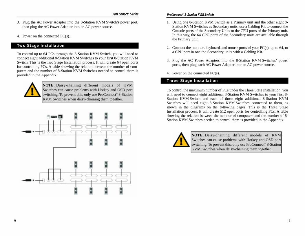
1. Plug your keyboard, mouse, and monitor into the 8-Station KVM Switch’sConsole ports.
2. Connect the monitor, keyboard, and mouse ports of your PC(s) to one of the8-Station KVM Switch’s CPU ports with a Cabling Kit.
Single Station Installation
4
1. Using one 8-Station KVM Switch as a Primary unit and the other eight 8-Station KVM Switches as Secondary units, use a Cabling Kit to connect theConsole ports of the Secondary Units to the CPU ports of the Primary unit.In this way, the 64 CPU ports of the Secondary units are available throughthe Primary unit.
2. Connect the monitor, keyboard, and mouse ports of your PC(s), up to 64, toa CPU port in one the Secondary units with a Cabling Kit.
3. Plug the AC Power Adapters into the 8-Station KVM Switches’ powerports, then plug each AC Power Adapter into an AC power source.
4. Power on the connected PC(s).
To control the maximum number of PCs under the Three State Installation, youwill need to connect eight additional 8-Station KVM Switches to your first 8-Station KVM Switch and each of those eight additional 8-Station KVMSwitches will need eight 8-Station KVM Switches connected to them, asshown in the diagrams on the following pages. This is the Three StageInstallation process. It will create 512 open ports for controlling PCs. A tableshowing the relation between the number of computers and the number of 8-Station KVM Switches needed to control them is provided in the Appendix.
Three Stage Installation
3. Plug the AC Power Adapter into the 8-Station KVM Switch’s power port,then plug the AC Power Adapter into an AC power source.
4. Power on the connected PC(s).
To control up to 64 PCs through the 8-Station KVM Switch, you will need toconnect eight additional 8-Station KVM Switches to your first 8-Station KVMSwitch. This is the Two Stage Installation process. It will create 64 open portsfor controlling PCs. A table showing the relation between the number of com-puters and the number of 8-Station KVM Switches needed to control them isprovided in the Appendix.
Two Stage Installation
NOTE: Daisy-chaining different models of KVMSwitches can cause problems with Hotkey and OSD portswitching. To prevent this, only use ProConnect® 8-StationKVM Switches when daisy-chaining them together.
NOTE: Daisy-chaining different models of KVMSwitches can cause problems with Hotkey and OSD portswitching. To prevent this, only use ProConnect® 8-StationKVM Switches when daisy-chaining them together.
6 7
ProConnect® Series ProConnect® 8-Station KVM Switch

1. Using one 8-Station KVMSwitch as a Primary unit andthe other eight 8-Station KVMSwitches as Secondary units,use a Cabling Kit to connect theConsole ports of the SecondaryUnits to the CPU ports of thePrimary unit.
2. For each Secondary unit, eightTertiary units will be connectedby using a Cabling Kit to con-nect the Console ports of theTertiary Units to the CPU portsof the Secondary unit. In thisway, the 64 CPU ports of theSecondary units are availablethrough the Primary unit.
3. Connect the monitor, keyboard,and mouse ports of your PC(s),up to 64, to a CPU port in onethe Secondary units with aCabling Kit.
4. Plug the AC Power Adapters into the 8-Station KVM Switches’ powerports, then plug each AC Power Adapter into an AC power source.
5. Power on the connected PC(s).
8 9
ProConnect® Series ProConnect® 8-Station KVM Switch

If it becomes necessary to power down an 8-Station KVM Switch, you mustperform the following prior to starting it back up:
1. Shut down all the PCs that are attached to the 8-Station KVM Switch, alongwith all other switches and PCs daisy chained.
2. Unplug the switch’s AC power cord.
3. After a minute, reconnect the power along with any PCs and daisy chainedswitches, starting with the last connection in the chain and working back tothe Primary switch.
4. After all of the connections have been made, power on the Primary switchand then any switches daisy chained. Next, power on the PCs connected.
The 8-Station KVM Switch provides three methods for obtaining instant accessany computer connected: Manual, Hotkey, and OSD (On Screen Display).
• Manual
Simply press the appropriate Port Selection switch on the switch’s front panelto select the computer connected to the corresponding port. After you press theswitch, the Selected LED lights to indicate that the port is currently selected.
When using the OSD function (as shown in Using the OSD Function), youcan initiate a Quick View Scan to cycle amongst the active ports.
• HotKey Navigation
HotKey navigation allows you to conveniently access any computer directlyfrom the keyboard, instead of having to manually select it with a Port Selectionswitch. Use the following method for HotKey navigation:
1) Press [CTRL] + [ALT] + [SHIFT] in sequence (not at the same time) toinvoke the HotKey function.
2) Key in the Port ID number (as shown in the following section), then pressthe Enter key. The Port ID number must be typed within one second ofinvoking HotKey navigation and should be typed from the keyboard, not thenumber pad.
Powering Off and Restarting
Port Selection
10
Using the ProConnect® 8-Station KVMSwitch
The 8-Station KVM Switch supports hot plugging - cables can be connected orunplugged without turning off the switches power. In order for hot plugging towork properly, however, these procedures must be followed:
• Hot Plugging CPU Ports
CPU port cables can be unplugged if necessary without powering down theswitch. If you reconnect the Cabling Kit (available from your nearest Linksysdealer) to the same port on the switch, the switch will immediately recognizethe PC. If you connect it to a different CPU port, the switch will need to rede-tect and initialize the connection.
• Hot Plugging Console Ports
The switch supports limited hot plugging of the keyboard, monitor, and mouse.Keyboards and monitors can be hot plugged on the Console ports. When hotplugging the mouse from the Console’s mouse port, however, the follow shouldbe considered:
1. You may unplug the mouse and plug it back in again (to reset the mouse,for example), as long as you use the exact same mouse.
2. If you plug in a different mouse, all of the switches and all the PCs con-nected to the switches must be shut down and restarted. (Refer to thePowering Off and Restarting section the follows.)
Hot Plugging
NOTE: If there is no response to mouse and/or keyboardinput, simultaneously press and hold Port Selection buttons1 and 2 on the Primary 8-Station KVM Switch for severalseconds to reset the keyboard and mouse connection.
11
ProConnect® Series ProConnect® 8-Station KVM Switch

2. To access a PC attached to Port 3 of a Two Stage installation, where the PCis attached to Port 3 of a Second Stage (or Secondary) unit that is cascad-ed down from Port 2 of the First Stage (or Primary) unit, key in 23 for thePort ID, as follows:
[CTRL] + [ALT] + [SHIFT] + 2 + 3 + [ENTER]
3. To access a PC attached to Port 1 of a Three Stage installation, where thePC is attached to Port 1 of a Third Stage (or Tertiary) unit that is cascadeddown from Port 4 of a Second Stage (or Secondary) unit, which, in turn, iscascaded down from Port 2 of the First Stage (or Primary) unit, key in 241for the Port ID, as follows:
[CTRL] + [ALT] + [SHIFT] + 2 + 4 + 1 + [ENTER]
HotKey Summary Table
[CTRL] + [ALT] + [SHIFT] + [0] +[ENTER]
COMBINATION
[CTRL] + [CTRL]
[SCROLL LOCK] + [SCROLLLOCK]
[CTRL] + [ALT] + [SHIFT] + [PortID number] + [ENTER]
Invokes Auto Scan Mode
ACTION
Invokes OSD (default)
Invokes OSD (alternate method)
Switches access to the PC thatcorresponds to the Port ID number(as shown in the above examples)
12
• Overview
Each CPU port on an 8-Station KVM Switch is assigned a unique Port ID. Youcan directly access any PC on any level of the installation by specifying the PortID of the CPU Port that the PC is connected to - either with HotKey navigationor from the OSD (as shown in Using the OSD Function).
The Port ID is a one, two, or three digit number that is determined by the StageLevel and the CPU Port number of the 8-Station KVM Switch where the PC isconnected. The first digit represents the CPU Port number of the First Stage (orPrimary) unit; the second digit represents the CPU Port number of the SecondStage (or Secondary) unit; the third digit represents the CPU Port number ofthe Third Stage (or Tertiary) unit.
For example, a PC attached to a First Stage (or Primary) unit has a one digitPort ID (from 1 to 8), that corresponds to the CPU Port number where the PCis connected.
A PC attached to a Second Stage (or Secondary) unit has a two digit Port ID.The first digit represents the CPU Port number on the First Stage (or Primary)unit that the Second Stage (or Secondary) unit links back to; the second digitrepresents the CPU Port number on the Second Stage (or Secondary) unitwhere the PC is connected. Therefore, a Port ID of 23 would refer to a com-puter that is connected to CPU Port 3 of the Second Stage (or Secondary) unitthat links back to CPU Port 2 of the First Stage (or Primary) unit.
Likewise, a computer attached to a Third Stage (or Tertiary) unit has a threedigit Port ID. One with a Port ID of 241 would be connected to CPU Port 1 ofa Third Stage (or Tertiary) unit, that links back to CPU Port 4 of a SecondStage (or Secondary) unit, which, in turn, links back to CPU Port 2 of the FirstStage (or Primary) unit.
• Port Key ID Examples
1. To access a PC attached to Port 3 of a Single Stage installation, key in 3 forthe Port ID, as follows:
[CTRL] + [ALT] + [SHIFT] + 3 + [ENTER]
Port ID Numbering
13
ProConnect® Series ProConnect® 8-Station KVM Switch

To cancel the current selection on the menu screen, press the ESC key. Thiswill also move back one menu screen and, if on the main menu screen, it willalso close the OSD menu.
To move up or down through the menu list, press the up or down arrows on yourkeyboard or click the Up or Down Triangles on the menu screen.
To move up or down through the menu screens, press the Page Up or PageDown keys on your keyboard or click the Up or Down arrows on the menuscreen.
To activate a port, move the Highlight Bar to it and press the Enter key.
After executing any action, you will automatically be brought back to the pre-vious menu screen.
HotKey navigation can also be used under OSD, as follows:
1. From the OSD Main Menu, press [CTRL] + [ALT] + [SHIFT] keys insequence (not at the same time).
2. Then, type in the Port ID for the computer you wish to access (refer to thePort ID Numbering section for more information on this), then press theEnter key. The Port ID number must be typed within one second of invok-ing HotKey navigation and should be typed from the keyboard, not thenumber pad.
The console now controls the computer that you have selected. The OSD willautomatically close.
OSD Menu Navigation
OSD HotKey Navigation
14
Using the On-Screen Display (OSD)
The On-Screen Display (OSD) provides a menu-driven interface to handle thecomputer switching procedure. OSD is a great deal more convenient thanHotKey switching, especially in large, daisy chained installations where it isdifficult to keep track of the port connection of a particular computer.
All operations start from the OSD Main Menu. To pop up the Main Menu, tapeither CTRL key twice. You can optionally change the OSD keys from theCTRL key to the Scroll Lock key from the OSD Main Menu. Thus, you wouldpress the Scroll Lock key twice.
When you invoke the OSD, a screen similar to that shown below will appear:
OSD always starts in List view, with the highlight bar at the same position itwas in the last time it was closed.
Overview
15
ProConnect® Series ProConnect® 8-Station KVM Switch

• F2 (Scan)
Pressing the F2 key initiates Quick View Scanning, in which the OSD cyclesthrough all of the ports that are currently selected in the List view (see F3,below), and displays each one for the amount of time specified with the SetScan Duration setting (see F6, Set). When you want to stop at a particular loca-tion, press the Spacebar to stop scanning.
As each computer is accessed, an [S] appears in front of the Port ID display onthe OSD to indicate that it is being accessed under Quick View Scan Mode.
• F3 (List)
This functions allows you to adjust the scope of which ports the OSD lists. Thesubmenu choices and their meanings are given in the table below:
Move the Highlight bar to the selection and press the Enter Key. An iconappears before the choice to indicate that it is selected.
NAME
CHOICE
All
QVIEW
POWERED ON +QVIEW
Lists on the ports that have been assignednames.
MEANING
Lists the Port ID numbers and names (if nameshave been specified, as shown under F5) of allactive ports.Lists only the ports that have been selected forQuick View scanning. (As shown under F4)
Lists only the ports that have been selected forQuick View scanning and have their attachedcomputers Powered ON.
QVIEW + NAME
POWERED ON
Lists only the ports that have been selected forQuick View scanning and have been assignednames.
Lists only the ports that have their attachedcomputers Powered ON.
16
Pressing a Function Key brings up a submenu that is used to configure and controlthe OSD. With these function keys, you can: rapidly switch to any port; scan select-ed ports; limit the list you wish to view; designate a port for Quick View scanning;create and edit a port name; or make OSD setting adjustments.
• F1 (GoTo)
Pressing the F1 key (Goto) allows you to switch directly to a port by either:
a) Moving the Highlight Bar to the port you want then press the Enter key;
or
b) Key in the Port ID or Name, then press the Enter key.
To return to the OSD Main Menu without making a choice, press the Escape key.
OSD Main Menu Headings
NAME
HEADING
PN
QV
PC
If a port has been given a name (F5 in The OSDFunction Keys), its name appears here.
EXPLANATION
This column lists the Port ID numbers for all theactive CPU Ports . The simplest method to access aparticular PC is to move the Highlight Bar to the PortID, then press the [Enter] key.
If a port has been selected for Quick View scanning(F2 and F4 in The OSD Function Keys), a triangle willappear in this column.
Lists all of the CPU ports currently active.
The OSD Function Keys
17
ProConnect® Series ProConnect® 8-Station KVM Switch

SETTING
Channel DisplayMode
Channel DisplayDuration
OSD ActivatingHotKey
FUNCTION
Selects how the Port ID is displayed: The PortNumber plus the Name (PN + NAME); the PortNumber alone (PN); or the Name alone (NAME).Determines how long a Port ID displays on themonitor after a port change has taken place: 3Seconds; or Always On.
Selects which HotKey activates the OSD func-tion: [CTRL] + [CTRL] or [SCROLL LOCK] +[SCROLL LOCK]. The default is the CTRL keycombination, but this may conflict with pro-grams running on the computers. In this case,the SCROLL LOCK option should be used.
Channel DisplayPosition
Scan Duration
Allows you to position where the Port ID appearson the screen. Use the Arrow Keys, Pg Up, Pg Dn,Home, End, and “5” (on the number pad withNum Lock off), to position the Port ID display.Then, press the [Enter] key to lock the positionand return to the Set submenu.
Determines how long the display dwells on eachport as it cycles through the selected ports inQuick View Scan Mode. The options are: 3, 5, 10,15, 20, 30, 40, and 60 seconds.
Set Password Allows you to set a password in order to controlaccess to: Clearing the Name List; RestoringDefault Values; and Locking/Unlocking theConsole. See the OSD Security Features sectionfor password setting details.
18
• F4 (Quick View)
Quick View allows you to select the ports you want to include for automaticscanning under the Quick View Scanning feature. Pressing the F4 key willselect and deselect a port when the Highlight Bar is over a specific port.When you have selected a port, a triangle will appear in the QV column.
• F5 (Edit)
To help remember which computer is attached to a particular port, every portcan be given a name. The Edit function allows to create, modify and deleteport names. To Edit a port name:
1. Move the Highlight bar to the port you want to edit.
2. Press the F5 key.
3. Type in the new Port Name, or modify/delete the old one. A port namecan be up to 15 alphanumeric characters in length and can also includethe “+”, “-”, “/”, “:”, “.” and “SPACE” characters. Port names are not casesensitive and will appear as uppercase.
4. When you have finished editing, press the Enter key to complete editing.To abort an edit, press the Escape key.
• F6 (Set)
Pressing the F6 key brings up the OSD configuration menu. To change a con-figuration setting:
1. Move the Highlight bar to the choice you want, then press the Enter key.
2. On the submenu that appears next, move the Highlight bar to the choiceyou want, then press the Enter key.
An icon of a pointing finger indicates which choice is currently selected. Anexplanation of the choices is shown in the table on the following pages.
19
ProConnect® Series ProConnect® 8-Station KVM Switch
In order to prevent unauthorized access to the PCs, the OSD provides a pass-word security feature. If a password has been set, the OSD will request that theuser provide it before allowing access.
To set a password:
1. Press the F6 key to bring up the setup configuration menu.
2. Move the Highlight bar to Set Password and press the Enter key.
3. Type in the new password and press the Enter key. (The password may beup to eight alphanumeric characters in length.)
4. Type in the new password again in order to confirm that it is correct andpress the Enter key. If the two entries do not match, an error message willdisplay, reading “PASSWORD NOT MATCH”. If this occurs, input yourpassword again.
To modify or delete a password:
1. Press the F6 key to bring up the setup configuration menu.
2. Move the Highlight bar to Set Password and press the Enter key.
3. To Delete the Password: Delete the password and press the Enter keyTo Modify the Password, Delete the previous password and type in the
new password and press the Enter key.
4. Type in the new password again in order to confirm that it is correct andpress the Enter key. If the two entries do not match, an error message willdisplay, reading “PASSWORD NOT MATCH”. If this occurs, input yourpassword again.
OSD Security
20
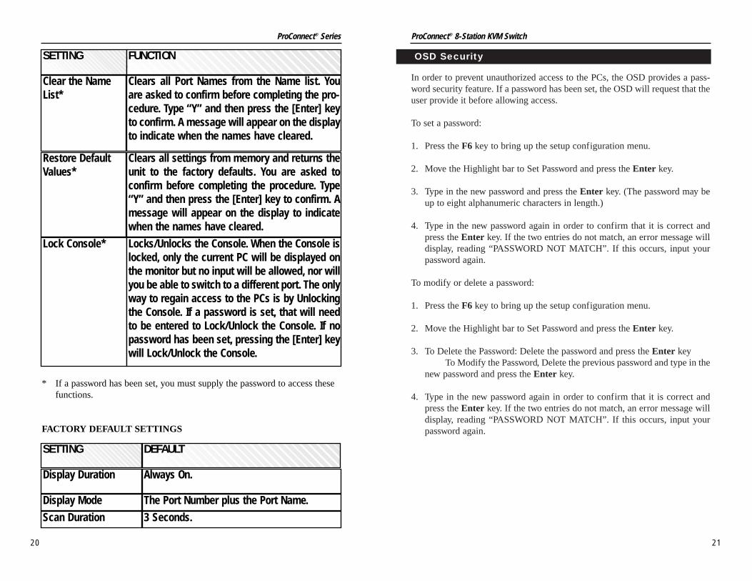
* If a password has been set, you must supply the password to access thesefunctions.
FACTORY DEFAULT SETTINGS
SETTING FUNCTION
Lock Console*
Clear the NameList*
Locks/Unlocks the Console. When the Console islocked, only the current PC will be displayed onthe monitor but no input will be allowed, nor willyou be able to switch to a different port. The onlyway to regain access to the PCs is by Unlockingthe Console. If a password is set, that will needto be entered to Lock/Unlock the Console. If nopassword has been set, pressing the [Enter] keywill Lock/Unlock the Console.
Clears all Port Names from the Name list. Youare asked to confirm before completing the pro-cedure. Type “Y” and then press the [Enter] keyto confirm. A message will appear on the displayto indicate when the names have cleared.
Restore DefaultValues*
Clears all settings from memory and returns theunit to the factory defaults. You are asked toconfirm before completing the procedure. Type“Y” and then press the [Enter] key to confirm. Amessage will appear on the display to indicatewhen the names have cleared.
SETTING
Display Duration
Display Mode
Scan Duration
DEFAULT
Always On.
The Port Number plus the Port Name.
3 Seconds.
21
ProConnect® Series ProConnect® 8-Station KVM Switch
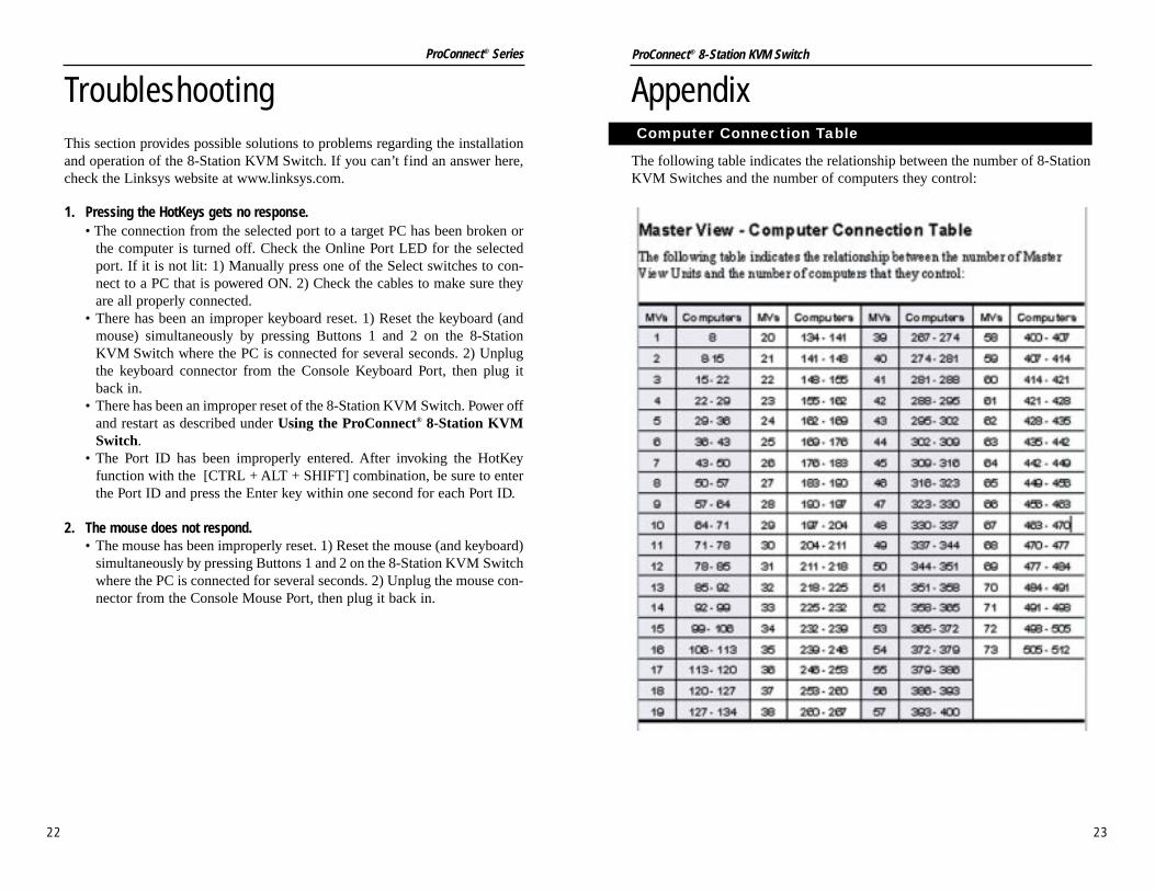
Appendix
The following table indicates the relationship between the number of 8-StationKVM Switches and the number of computers they control:
Computer Connection Table
22
TroubleshootingThis section provides possible solutions to problems regarding the installationand operation of the 8-Station KVM Switch. If you can’t find an answer here,check the Linksys website at www.linksys.com.
1. Pressing the HotKeys gets no response.• The connection from the selected port to a target PC has been broken or
the computer is turned off. Check the Online Port LED for the selectedport. If it is not lit: 1) Manually press one of the Select switches to con-nect to a PC that is powered ON. 2) Check the cables to make sure theyare all properly connected.
• There has been an improper keyboard reset. 1) Reset the keyboard (andmouse) simultaneously by pressing Buttons 1 and 2 on the 8-StationKVM Switch where the PC is connected for several seconds. 2) Unplugthe keyboard connector from the Console Keyboard Port, then plug itback in.
• There has been an improper reset of the 8-Station KVM Switch. Power offand restart as described under Using the ProConnect® 8-Station KVMSwitch.
• The Port ID has been improperly entered. After invoking the HotKeyfunction with the [CTRL + ALT + SHIFT] combination, be sure to enterthe Port ID and press the Enter key within one second for each Port ID.
2. The mouse does not respond.• The mouse has been improperly reset. 1) Reset the mouse (and keyboard)
simultaneously by pressing Buttons 1 and 2 on the 8-Station KVM Switchwhere the PC is connected for several seconds. 2) Unplug the mouse con-nector from the Console Mouse Port, then plug it back in.
23
ProConnect® Series ProConnect® 8-Station KVM Switch

24
Dimensions: 14.5” x 9.75” x 1.75” (368mm x 248mm x 44mm)
Unit Weight: 120 oz. (3.4 Kg)
Power: 9V DC 1.62W maximum
Certifications: FCC Class B, CE Mark Commercial
Operating Temp: 5ºC to 40ºC (41ºF to 104ºF)
Storage Temp: -10ºC to 60ºC (14ºF to 140ºF)
Operating Humidity: 10% to 85%, Non-Condensing
Storage Humidity: 5% to 90%, Non-Condensing
Environmental
ProConnect® 8-Station KVM Switch
25
ProConnect® Series
SpecificationsModel Numbers SVIEW08
Computer Connections Direct: 8Max: 512
Protocol CSMA/CD
Ports Console:Keyboard - One 6-pin mini-DIN femaleMouse - One 6-pin mini-DIN femaleVideo - One HDB-15 female (VGA/SVGA)
CPU: Eight 25-pin D Type female
Scan Intervals 3, 5, 10, 15, 20, 30, 40, and 60 seconds
Monitors Supported VGA, SVGA, and MultiSync with DDC, DDC2, and DDC2B
Maximum Resolution 1920 x 1440 SVGA
LEDs Eight Orange On-line PortEight Green Selected Port

26
Contact Information
For help with the installation or operation of this product, contact LinksysCustomer Support at one of the phone numbers or Internet addresses below.
Sales Information 800-546-5797 (LINKSYS)Tech Support 800-326-7114RMA Issues 949-261-1288Fax 949-261-8868Email [email protected] http://www.linksys.comFTP Site ftp.linksys.com
ProConnect® 8-Station KVM Switch
27
ProConnect® Series
Warranty InformationBE SURE TO HAVE YOUR PROOF OF PURCHASE AND A BARCODEFROM THE PRODUCT'S PACKAGING ON HAND WHEN CALLING.RETURN REQUESTS CANNOT BE PROCESSED WITHOUT PROOF OFPURCHASE.
IN NO EVENT SHALL LINKSYS’ LIABILITY EXCEED THE PRICE PAIDFOR THE PRODUCT FROM DIRECT, INDIRECT, SPECIAL, INCIDEN-TAL, OR CONSEQUENTIAL DAMAGES RESULTING FROM THE USEOF THE PRODUCT, ITS ACCOMPANYING SOFTWARE, OR ITS DOCU-MENTATION. LINKSYS DOES NOT OFFER REFUNDS FOR ANY PROD-UCT.
LINKSYS OFFERS CROSS SHIPMENTS, A FASTER PROCESS FOR PRO-CESSING AND RECEIVING YOUR REPLACEMENT. LINKSYS PAYSFOR UPS GROUND ONLY. ALL CUSTOMERS LOCATED OUTSIDE OFTHE UNITED STATES OF AMERICA AND CANADA SHALL BE HELDRESPONSIBLE FOR SHIPPING AND HANDLING CHARGES. PLEASECALL LINKSYS FOR MORE DETAILS.

© Copyright 2001 Linksys, All Rights Reserved.
http://www.linksys.com