Procon A1M - Alklima Klimaatapparatuur Handleiding... · Use only shielded cables for connecting...
48
Procon A1M FOR INSTALLERS INSTALLATION MANUAL Version 2.0.6 Firmware version 2.0.6 For safe and correct use, please read this installation manual thoroughly before installing the PROCON A1M.
Transcript of Procon A1M - Alklima Klimaatapparatuur Handleiding... · Use only shielded cables for connecting...

Procon A1M FOR INSTALLERS
INSTALLATION MANUAL Version 2.0.6 Firmware version 2.0.6 For safe and correct use, please read this installation manual thoroughly before installing the PROCON A1M.

• i •
Preface
Safety warnings
Caution: Do not expose to rain or moisture.
Shielded Signal Cables: Use only shielded cables for connecting peripherals to any Procon A1M device to reduce the possibility of interference with radio communications services. Using shielded cables ensures that you maintain the appropriate EMC classification for the intended environment.
CE Notice: This product has been determined to be in compliance with 2004/108/EC (EMC Directive) and amendments of the European Union.
European Union, Class A: Class A products are intended for use in non-residential/non-domestic environments. Class A products may also be utilized in residential/domestic environments but may cause interference and require the user to take adequate corrective measures. This is a Class A product. In a domestic environment this product may cause radio frequency interference in which case the user may be required to take adequate measures. A “Declaration of Conformity” in accordance with the preceding directives and standards has been made and is available on request. If this equipment does cause interference with radio communications services, which can be determined by turning the equipment off and on, you are encouraged to try to correct the interference by one or more of the following measures: Reorient the receiving antenna. Relocate the Procon A1M with respect to the receiver. Move the Procon A1M away from the receiver. If necessary, consult a Procon A1M technical support representative or an experienced radio/television or EMC technician for additional suggestions.
Disclaimer
Warranty: All products manufactured on behalf of Mitsubishi Electric UK are warranted against defective materials for a period of three years from the date of delivery to the original purchaser.
Warning: Mitsubishi Electric UK assumes no liability for damages consequent to the user of this product. We reserve the right to change this manual at any time without notice. The information furnished by us is believed to be accurate and reliable. However, no responsibility is assumed by us for its use, nor for any infringements of patents or other rights of third parties resulting from its use.

A RS-485 connector
B CN105/CN92 connection lead
1 [Fig. 1]
A
B

Page 2 of 43
2 [Fig. 2]
Air to air unit
Air to water unit
Page 3 of 43
Contents Preface ............................................................................................................................................................................. i
Safety warnings ............................................................................................................................................................ i Disclaimer ..................................................................................................................................................................... i
1. Safety precautions ................................................................................................................................................ 4 2. Overview ................................................................................................................................................................ 5 3. DIP switch settings ............................................................................................................................................... 6
3.1. Modbus Slave ID ............................................................................................................................................ 6 3.2. RS-485 communication settings ..................................................................................................................... 6 3.3. Protocol selection ........................................................................................................................................... 6 3.4. Deadband Mode ............................................................................................................................................. 7
4. Deadband Mode .................................................................................................................................................... 8 4.1. Settings .......................................................................................................................................................... 8 4.2. Operation........................................................................................................................................................ 8 4.3. Initialisation..................................................................................................................................................... 9
5. Setpoint Offset .................................................................................................................................................... 10 5.1. Settings ........................................................................................................................................................ 10 5.2. Operation...................................................................................................................................................... 10
6. RS-485 termination ............................................................................................................................................. 12 7. Installation ........................................................................................................................................................... 13
7.1. Physical connection ...................................................................................................................................... 13 7.2. Power supply ................................................................................................................................................ 13 7.3. Modbus connections .................................................................................................................................... 13 7.4. Unit type selection ........................................................................................................................................ 13
8. Status LEDs ........................................................................................................................................................ 14 8.1. AC ACK ........................................................................................................................................................ 14 8.2. RS-485 ACK ................................................................................................................................................. 14
9. Modbus connection ............................................................................................................................................ 15 9.1. Modbus background ..................................................................................................................................... 15 9.2. Modbus registers .......................................................................................................................................... 15 9.3. Modbus connections .................................................................................................................................... 15
10. Modbus tables – Air-To-Air systems ................................................................................................................. 17 10.1. Discrete Inputs ............................................................................................................................................. 17 10.2. Coils ............................................................................................................................................................. 17 10.3. Input registers ............................................................................................................................................... 17 10.4. Holding registers .......................................................................................................................................... 18
11. Modbus tables – Air-To-Water systems ............................................................................................................ 20 11.1. Holding registers .......................................................................................................................................... 20 11.2. Input registers ............................................................................................................................................... 32 11.3. Coils ............................................................................................................................................................. 39 11.4. Discrete Inputs ............................................................................................................................................. 39
Appendix A – Compatible Air-To-Air units ................................................................................................................. 42 Appendix B – Compatible Air-To-Water units ............................................................................................................ 43

Page 4 of 43
1. Safety precautions
Symbols used in the text
Warning: Describes precautions that should be observed to prevent danger of injury or death to the user.
Caution: Describes precautions that should be observed to prevent damage to the unit.
Warning: • Ask the dealer or an authorised technician to install the unit - Improper installation by the user may result in electric shock, or fire • Use the specified cables for wiring. Make the connections securely so that any outside forces acting on the cables are
not applied to the terminals - Inadequate connection and fastening may generate heat and cause a fire • Never repair the unit. If the controller must be repaired, consult the dealer - If the unit is repaired improperly, electric shock, or fire may result • Have all electric work done by a licensed electrician according to "Electric Facility Engineering Standard", "Interior Wire
Regulations" and the instructions given in this manual and always use a special circuit - If the power source capacity is inadequate or electric work is performed improperly, electric shock and fire may result • Keep the electric parts away from any water - washing water etc… - Contact may result in electric shock, fire or smoke • To dispose of this product, consult your dealer
Caution: • Safely dispose of the packing materials - Packing materials, such as nails and other metal or wooden parts, may cause stabs or other injuries - Tear apart and throw away plastic packaging bags so that children will not play with them - If children play with a plastic bag
which has not been torn apart, they face the risk of suffocation
Before installing the unit, make sure you read all the “Safety precautions”
The “Safety precautions” provide very important points
regarding safety. Make sure you follow them

Page 5 of 43
2. Overview The Procon A1M Protocol Converter is used for remote monitoring and control of both Air-to-Air products (M-, S- and P-series split air conditioning systems) and Air-to-Water products (CAHV, CRHV, PWFY). It acts as a gateway between the system and external third party equipment. The A1M continuously reads data from the system and changes configuration when necessary. Because the reading is continuous the A1M always stores up-to-date data. This data is then available to external devices through the RS-485 port using the Modbus RTU software protocol. Values can be read and changed via this connection. Please refer to the Modbus section for further information. The A1M is powered via the CN105/CN92 connector, hence no external power supply is needed. Compatible Air-To-Air model numbers can be found in Appendix A of this document.
Caution: MAC-397IF and MAC-399IF units cannot be connected when the Procon A1M is connected, as the same CN105/CN92 connector is used. Appendix A lists the compatible Air-To-Water indoor units. Figure 1 shows the A1M converter. Figure 2 shows the CN105/CN92 connector on the indoor unit PCB that the A1M connects to, for both Air-to-Air and Air-To-Water type units.

Page 6 of 43
3. DIP switch settings There is a bank of 8 DIP switches on the Procon A1M PCB labeled ‘CONFIGURATION’. These switches are used to configure communication settings and to enable some features.
3.1. Modbus Slave ID Any Modbus Slave ID in the range 1 – 30 can be chosen using switches 1 – 5. The address is set in binary, where the switch positions have the following values:
Switch number Value when switch is set to ON 1 1 2 2 3 4 4 8 5 16
To get the Slave ID, add together the value for each switch set ON. For example, to set address 13, set switches 1, 3 and 4 ON (1 + 4 + 8 = Slave ID 13). When all switches 1 – 5 are set to the ON position the Modbus Slave ID is set in software by writing to a Modbus register (see Modbus Holding Registers section). When all switches are set to the OFF position a Modbus Slave ID of 1 is assumed. Note: Each Procon A1M connected to the same RS-485 network must be set to a unique address.
3.2. RS-485 communication settings The RS-485 settings are set using DIP switch 6. When the switch is in the OFF position the Baud Rate and Parity settings are set in software by writing to Modbus registers (see Modbus Holding Register section).
Switch 6 RS-485 communication settings OFF Baud Rate and Parity set in software ON 9600 baud, no parity
The number of data bits is fixed at 8 and the number of stop bits is fixed at 1.
3.3. Protocol selection The RS485 protocol is set using DIP switch 7. When the switch is in the ON position the Modbus RTU protocol is selected.
Switch 7 Protocol selection OFF Undefined ON Modbus RTU

Page 7 of 43
3.4. Deadband Mode The Deadband feature can be enabled using DIP switch 8. When the switch is in the OFF position the Deadband feature is disabled. When the switch is in the ON position the Deadband feature is enabled.
Switch 8 Deadband feature OFF Disabled ON Enabled

Page 8 of 43
4. Deadband Mode The deadband mode is enabled by setting DIP switch 8 ON. It is only applicable to Air-To-Air type units.
4.1. Settings There are two settings, the Heating Setpoint (default 19º) and Cooling Setpoint (default 23ºC). These values can be changed via Modbus, refer to the Air-To-Air Modbus tables for more information. The Cooling Setpoint must be at least 2ºC greater than the Heating Setpoint, otherwise the default values given above will be assumed.
4.2. Operation When enabled, the Procon A1M controls the Mode and Temperature Setpoint based on the Room (return air) Temperature. While the room temperature is less than the Heating Setpoint the unit will be set to HEAT mode with a setpoint of 28ºC. Whilst in HEAT mode, if the room temperature rises above the Heating Setpoint + 1ºC the unit will be set to FAN mode. Whilst in FAN mode, if the temperature rises above the Cooling Setpoint the unit will be set to COOL mode with a setpoint of 19ºC. Whilst in COOL mode, if the room temperature falls below the Cooling Setpoint – 1ºC the unit will be set to FAN mode. Whilst in FAN mode, if the room temperature falls below the Heating Setpoint the unit will be set to HEAT mode with a setpoint of 28ºC. The following image shows this graphically (assuming a Heating Setpoint of 19ºC and a Cooling Setpoint of 23ºC):

Page 9 of 43
4.3. Initialisation When the Procon A1M powers up it will set the mode, which will be determined by the room temperature. If less than the Heating Setpoint the unit will be set to HEAT mode with a setpoint of 28ºC. If greater than or equal to the Cooling Setpoint the unit will be set to COOL mode with a setpoint of 19ºC. If between the Heating and Cooling Setpoints the unit will be set to FAN mode.

Page 10 of 43
5. Setpoint Offset The Setpoint Offset feature is only applicable to, and will only be enabled for, Air-To-Air type units.
5.1. Settings There are two settings which are applicable to the Setpoint Offset feature, BMS Room Temperature and BMS Virtual Setpoint. The BMS Virtual Setpoint can be changed using Modbus and is stored in non-volatile memory so the value is retained if the A1M loses power. The BMS Room Temperature can be changed using Modbus but is not stored in non-volatile memory, so the value is lost and reset to zero upon the A1M losing power.
5.2. Operation In some situations a 3rd party room temperature sensor connected to a BMS or other controller may provide a more accurate temperature reading than the return air temperature of the indoor unit. The A1M can calculate the difference between these two temperature readings and compensate by adjusting the indoor unit’s temperature setpoint. The new temperature setpoint is calculated using the following equation: Temperature Setpoint = Return Air Temperature – (BMS Room Temperature – BMS Virtual Temperature) As an hypothetical example, consider the BMS Virtual Setpoint being set to 21ºC and the indoor unit return air temperature remaining constant at 22ºC. As the BMS Room Temperature decreases the A1M increases the indoor unit’s temperature setpoint. When the BMS Room Temperature reaches 18ºC the Temperature Setpoint = 22 – (18 – 21) = 25ºC.
Hysteresis has been built in to prevent the temperature setpoint from rapidly changing. The setpoint offset will only operate correctly if the BMS Room Temperature is periodically updated via Modbus, to ensure the A1M always has an up to date reading.

Page 11 of 43
If the BMS Room Temperature is set to 0ºC (which it will be on power up) the setpoint offset feature will be disabled. It will only activate when the BMS Room Temperature is not 0ºC. To disable the feature without removing the A1M power, simply set the BMS Room Temperature to 0ºC.

Page 12 of 43
6. RS-485 termination
An RS-485 termination resistor can be enabled on the A1M PCB using the single jumper labeled J1. The jumper setting is summarised below:
Jumper Setting Description Not fitted Termination resistor not enabled
Fitted Termination resistor enabled

Page 13 of 43
7. Installation
7.1. Physical connection The Procon A1M has a 1 metre flying lead to connect directly into the CN105/CN92 connector on the controller PCB. As an example, Figure 2 shows this connection on a Mr Slim indoor unit and a CRHV unit.
7.2. Power supply The Procon A1M is powered from the CN105/CN92 connector and hence does not require an external power supply.
7.3. Modbus connections The Procon A1M has a 3-way screw terminal to provide Modbus RTU communication via RS-485. Figure 1 shows the RS-485 connections. The Modbus section contains further detail of the Modbus communications.
7.4. Unit type selection The Procon A1M software will automatically detect whether an Air-To-Air or Air-To-Water unit is connected. It will then only send commands applicable to that unit type.

Page 14 of 43
8. Status LEDs There are two status LEDs on the Procon A1M. The LED indications are as follows:
LED Name Colour Functionality
AC ACK Green Lit when A1M is powered, flashing indicates valid communication with the indoor unit.
RS-485 ACK Green Lit when A1M is powered, flashing indicates valid Modbus communication.
8.1. AC ACK If this LED is permanently lit and does not flash, check the CN105/CN92 connection is secure.
8.2. RS-485 ACK If this LED is permanently lit and does not flash it could be due to a physical RS-485 connection problem, or incorrect Modbus/RS-485 configuration.
Page 15 of 43
9. Modbus connection
9.1. Modbus background Modbus is a master-slave protocol, which means there are two types of Modbus device, Modbus Masters and Modbus Slaves. Slave devices simply wait until they receive a command from a Master, act upon that command and send a reply to the Master. Slaves do not have the ability to send commands to other devices on the bus. Master devices are responsible for sending commands to slave devices and receiving data. Modbus only permits there to be one Master device on the bus at any one time, but up to 247 slaves can be connected at a time. Modbus is most commonly used over RS-485, which is a hardware standard allowing multiple devices to be connected on the same bus. Each Slave device must have a unique ID on the bus, which is referred to as a Slave ID. Each Modbus command the Master sends will contain this Slave ID and only the Slave with that Slave ID will reply.
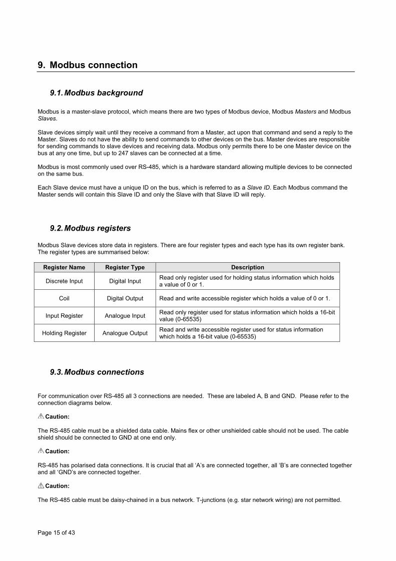
9.2. Modbus registers Modbus Slave devices store data in registers. There are four register types and each type has its own register bank. The register types are summarised below:
Register Name Register Type Description
Discrete Input Digital Input Read only register used for holding status information which holds a value of 0 or 1.
Coil Digital Output Read and write accessible register which holds a value of 0 or 1.
Input Register Analogue Input Read only register used for status information which holds a 16-bit value (0-65535)
Holding Register Analogue Output Read and write accessible register used for status information which holds a 16-bit value (0-65535)
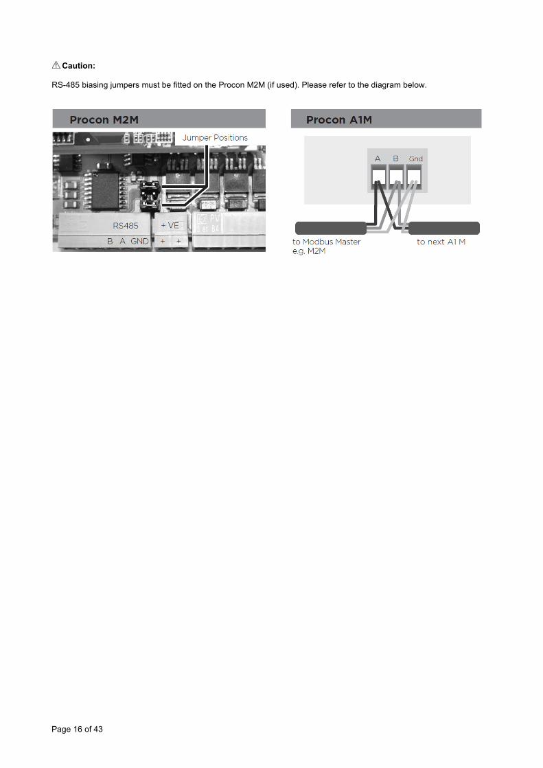
9.3. Modbus connections For communication over RS-485 all 3 connections are needed. These are labeled A, B and GND. Please refer to the connection diagrams below.
Caution: The RS-485 cable must be a shielded data cable. Mains flex or other unshielded cable should not be used. The cable shield should be connected to GND at one end only.
Caution: RS-485 has polarised data connections. It is crucial that all ‘A’s are connected together, all ‘B’s are connected together and all ‘GND’s are connected together.
Caution: The RS-485 cable must be daisy-chained in a bus network. T-junctions (e.g. star network wiring) are not permitted.
Page 16 of 43
Caution: RS-485 biasing jumpers must be fitted on the Procon M2M (if used). Please refer to the diagram below.
Page 17 of 43
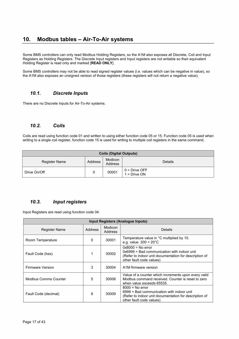
10. Modbus tables – Air-To-Air systems Some BMS controllers can only read Modbus Holding Registers, so the A1M also exposes all Discrete, Coil and Input Registers as Holding Registers. The Discrete Input registers and Input registers are not writable so their equivalent Holding Register is read only and marked [READ ONLY]. Some BMS controllers may not be able to read signed register values (i.e. values which can be negative in value), so the A1M also exposes an unsigned version of those registers (these registers will not return a negative value).
10.1. Discrete Inputs There are no Discrete Inputs for Air-To-Air systems.
10.2. Coils Coils are read using function code 01 and written to using either function code 05 or 15. Function code 05 is used when writing to a single coil register, function code 15 is used for writing to multiple coil registers in the same command.
Coils (Digital Outputs)
Register Name Address Modicon Address Details
Drive On/Off 0 00001 0 = Drive OFF 1 = Drive ON
10.3. Input registers Input Registers are read using function code 04.
Input Registers (Analogue Inputs)
Register Name Address Modicon Address Details
Room Temperature 0 30001 Temperature value in °C multiplied by 10. e.g. value 200 = 20°C
Fault Code (hex) 1 30002
0x8000 = No error 0x6999 = Bad communication with indoor unit (Refer to indoor unit documentation for description of other fault code values)
Firmware Version 3 30004 A1M firmware version
Modbus Comms Counter 5 30006 Value of a counter which increments upon every valid Modbus command received. Counter is reset to zero when value exceeds 65535.
Fault Code (decimal) 8 30009
8000 = No error 6999 = Bad communication with indoor unit (Refer to indoor unit documentation for description of other fault code values)
Page 18 of 43
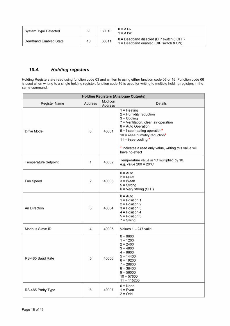
System Type Detected 9 30010 0 = ATA 1 = ATW
Deadband Enabled State 10 30011 0 = Deadband disabled (DIP switch 8 OFF) 1 = Deadband enabled (DIP switch 8 ON)
10.4. Holding registers Holding Registers are read using function code 03 and written to using either function code 06 or 16. Function code 06 is used when writing to a single holding register, function code 16 is used for writing to multiple holding registers in the same command.
Holding Registers (Analogue Outputs)
Register Name Address Modicon Address Details
Drive Mode 0 40001
1 = Heating 2 = Humidity reduction 3 = Cooling 7 = Ventilation, clean air operation 8 = Auto Operation 9 = i-see heating operation* 10 = i-see humidity reduction* 11 = i-see cooling * * indicates a read only value, writing this value will have no effect
Temperature Setpoint 1 40002 Temperature value in °C multiplied by 10. e.g. value 200 = 20°C
Fan Speed 2 40003
0 = Auto 2 = Quiet 3 = Weak 5 = Strong 6 = Very strong (SH i)
Air Direction 3 40004
0 = Auto 1 = Position 1 2 = Position 2 3 = Position 3 4 = Position 4 5 = Position 5 7 = Swing
Modbus Slave ID 4 40005 Values 1 – 247 valid
RS-485 Baud Rate 5 40006
0 = 9600 1 = 1200 2 = 2400 3 = 4800 4 = 9600 5 = 14400 6 = 19200 7 = 28800 8 = 38400 9 = 56000 10 = 57600 11 = 115200
RS-485 Parity Type 6 40007 0 = None 1 = Even 2 = Odd

Page 19 of 43
Drive On/Off 7 40008 0 = Drive OFF 1 = Drive ON
Room Temperature [READ ONLY] 8 40009 Temperature value in °C multiplied by 10.
e.g. value 200 = 20°C
Fault Code (hex) [READ ONLY] 9 40010
0x8000 = No error 0x6999 = Bad communication with indoor unit (Refer to indoor unit documentation for description of other fault code values)
Firmware Version [READ ONLY] 10 40011 A1M firmware version
Modbus Comms Counter [READ ONLY] 11 40012
Value of a counter which increments upon every valid Modbus command received. Value is automatically reset to zero when value exceeds 65535.
Fault Code (decimal) [READ ONLY] 12 40013
8000 = No error 6999 = Bad communication with indoor unit (Refer to indoor unit documentation for description of other fault code values)
System Type Detected [READ ONLY] 13 40014 0 = ATA
1 = ATW
Deadband Enabled State [READ ONLY] 14 40015 0 = Deadband disabled (DIP switch 8 OFF)
1 = Deadband enabled (DIP switch 8 ON)
BMS Room Temperature (signed) 15 40016 Signed temperature value in ºC multiplied by 10. 0xFF9C = -10ºC … 0x01F4 = 50ºC
BMS Room Temperature 16 40017 Temperature value in ºC multiplied by 10. 0 = 0ºC … 500 = 50ºC
BMS Virtual Setpoint 17 40018 Temperature value in ºC multiplied by 10. 100 = 10ºC … 400 = 40ºC
Deadband Heating Setpoint 18 40019 Temperature in ºC (default 19ºC). Value must be at least 2ºC lower than the Deadband Cooling Setpoint.
Deadband Cooling Setpoint 19 40020 Temperature in ºC (default 23ºC). Value must be at least 2ºC higher than the Deadband Heating Setpoint.

Page 20 of 43
11. Modbus tables – Air-To-Water systems Some BMS controllers can only read Modbus Holding Registers, so the A1M also exposes all Discrete, Coil and Input Registers as Holding Registers. The Discrete Input registers and Input registers are not writable so their equivalent Holding Register is read only and marked [READ ONLY]. Some BMS controllers may not be able to read signed register values (i.e. values which can be negative in value), so the A1M also exposes an unsigned version of those registers (these registers will not return a negative value).
11.1. Holding registers Holding Registers are read using function code 03 and written to using either function code 06 or 16. Function code 06 is used when writing to a single holding register, function code 16 is used for writing to multiple holding registers in the same command.
Holding Register (Analogue Output) Applicable Unit Type
Register Name Addr Modicon Address Details
FTC
4
FTC
5
CA
HV
mas
ter
CA
HV
slav
e C
RH
V m
aste
r C
RH
V sl
ave
Modbus Slave ID 4 40005 Values 1 – 247 valid
RS-485 Baud Rate 5 40006
0 = 9600 1 = 1200 2 = 2400 3 = 4800 4 = 9600 5 = 14400 6 = 19200 7 = 28800 8 = 38400 9 = 56000 10 = 57600 11 = 115200
RS-485 Parity Type 6 40007 0 = None 1 = Even 2 = Odd
Fault/Error Code (hex) [READ ONLY] 9 40010
0x8000 = No error 0x6999 = Bad communication with unit (Refer to indoor unit documentation for description of other fault code values)
A1M Firmware Version [READ ONLY] 10 40011 A1M firmware version
Modbus Comms Counter [READ ONLY] 11 40012
Value of a counter which increments upon every valid Modbus command received. Counter is reset to zero when value exceeds 65535.
Fault Code (decimal) [READ ONLY] 12 40013
8000 = No error 6999 = Bad communication between A1M and unit (Refer to unit documentation for description of other fault code values)
System Type Detected [READ ONLY] 13 40014 0 = A1M has detected an ATA unit connected
1 = A1M has detected an ATW system connected
System On/Off 25 40026
0 = System OFF 1 = System ON 2 = Emergency Run (read only value) 3 = Test Run (read only value)
Operating Mode 26 40027 0 = Stop 1 = Hot Water 2 = Heating
#4 #5

Page 21 of 43
3 = Cooling 5 = Freeze Stat 6 = Legionella 7 = Heating-Eco
Operating Mode (DHW) 27 40028 0 = Normal 1 = Eco
A/C Mode – Zone 1 28 40029
0 = Heating Room Temp 1 = Heating Flow Temp 2 = Heating Heat Curve 3 = Cooling Room Temp (not on 13K model) 4 = Cooling Flow Temp 5 = Floor Dryup
A/C Mode – Zone 2 29 40030
0 = Heating Room Temp 1 = Heating Flow Temp 2 = Heating Heat Curve 3 = Cooling Room Temp (not on 13K model) 4 = Cooling Flow Temp 5 = Floor Dryup
Set Tank Water Temperature (signed) 30 40031 Temperature value in ºC multiplied by 100.
(see note *) #6
Set Tank Water Temperature 31 40032 Temperature value in ºC multiplied by 100. (see note **) #6
H/C Thermostat Target Temperature – Zone 1 (signed) 32 40033 Temperature value in ºC multiplied by 100.
(see note *)
H/C Thermostat Target Temperature – Zone 1 33 40034 Temperature value in ºC multiplied by 100.
(see note **)
H/C Thermostat Target Temperature – Zone 2 (signed) 34 40035 Temperature value in ºC multiplied by 100.
(see note *)
H/C Thermostat Target Temperature – Zone 2 35 40036 Temperature value in ºC multiplied by 100.
(see note **)
MRC Prohibit 36 40037
Bit packed value: Bit 0 – System On/Off (0 = ON, 1 = Prohibit) Bit 1 – Running Mode (0 = ON, 1 = Prohibit) Bit 2 – Setting Temp (0 = ON, 1 = Prohibit) Bit 3 – Undefined (always 0) Bit 4 – Function Setting (0 = Normal, 1 = Function Setting) Bits 5, 6 and 7 – Undefined (always 0) (Before using this register see note ††)
#7 #7
Force DHW 37 40038 0 = Normal 1 = Force DHW
Holiday 38 40039 0 = Normal 1 = Holiday
DHW On Prohibit 39 40040 0 = On 1 = Prohibit #6
Heating On Prohibit – Zone 1 40 40041 0 = On 1 = Prohibit #6
Cooling On Prohibit – Zone 1 41 40042 0 = On 1 = Prohibit #6
Heating On Prohibit – Zone 2 42 40043 0 = On 1 = Prohibit #6
Cooling On Prohibit – Zone 2 43 40044 0 = On 1 = Prohibit
Unused 44 40045 Value 0 always returned
Capacity Mode 45 40046 0 = COP priority 1 = Capacity priority #8 #8
Capacity Control Ratio 46 40047 Value in %. 0 = 0% ... 100 = 100%
Page 22 of 43
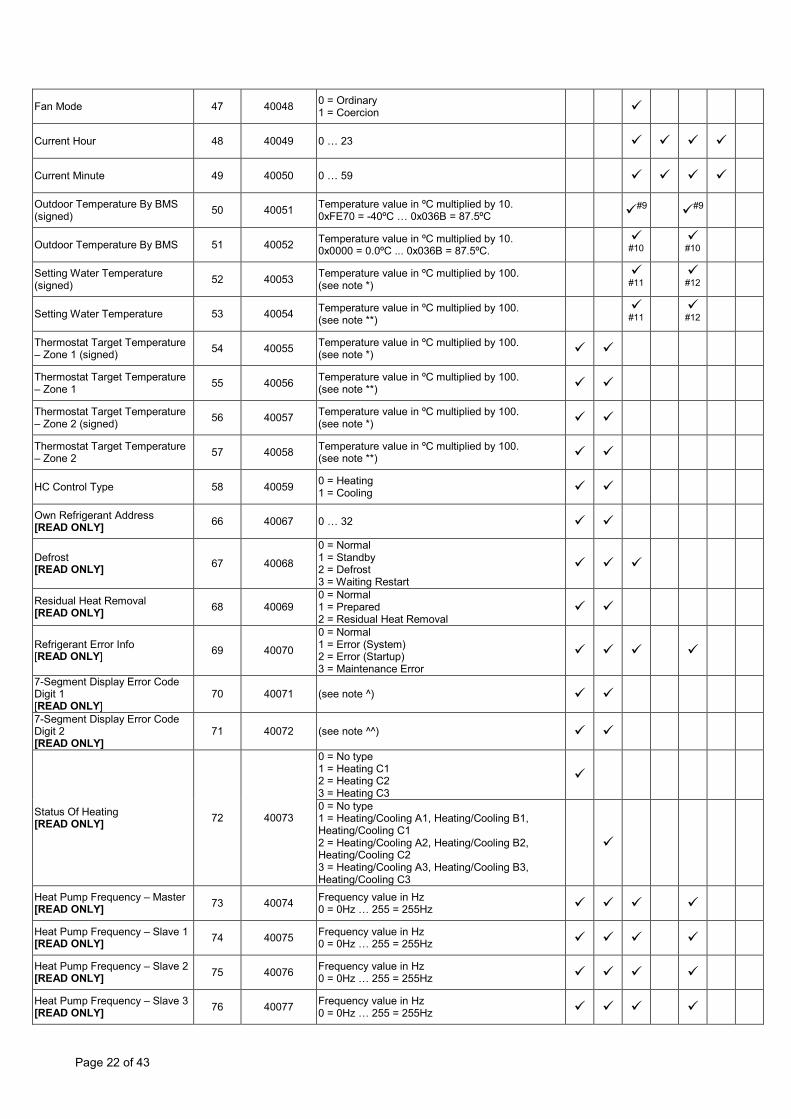
Fan Mode 47 40048 0 = Ordinary 1 = Coercion
Current Hour 48 40049 0 … 23
Current Minute 49 40050 0 … 59
Outdoor Temperature By BMS (signed) 50 40051 Temperature value in ºC multiplied by 10.
0xFE70 = -40ºC … 0x036B = 87.5ºC #9 #9
Outdoor Temperature By BMS 51 40052 Temperature value in ºC multiplied by 10. 0x0000 = 0.0ºC ... 0x036B = 87.5ºC.
#10 #10
Setting Water Temperature (signed) 52 40053 Temperature value in ºC multiplied by 100.
(see note *) #11
#12
Setting Water Temperature 53 40054 Temperature value in ºC multiplied by 100. (see note **)
#11 #12
Thermostat Target Temperature – Zone 1 (signed) 54 40055 Temperature value in ºC multiplied by 100.
(see note *)
Thermostat Target Temperature – Zone 1 55 40056 Temperature value in ºC multiplied by 100.
(see note **)
Thermostat Target Temperature – Zone 2 (signed) 56 40057 Temperature value in ºC multiplied by 100.
(see note *)
Thermostat Target Temperature – Zone 2 57 40058 Temperature value in ºC multiplied by 100.
(see note **)
HC Control Type 58 40059 0 = Heating 1 = Cooling
Own Refrigerant Address [READ ONLY] 66 40067 0 … 32
Defrost [READ ONLY] 67 40068
0 = Normal 1 = Standby 2 = Defrost 3 = Waiting Restart
Residual Heat Removal [READ ONLY] 68 40069
0 = Normal 1 = Prepared 2 = Residual Heat Removal
Refrigerant Error Info [READ ONLY] 69 40070
0 = Normal 1 = Error (System) 2 = Error (Startup) 3 = Maintenance Error
7-Segment Display Error Code Digit 1 [READ ONLY]
70 40071 (see note ^)
7-Segment Display Error Code Digit 2 [READ ONLY]
71 40072 (see note ^^)
Status Of Heating [READ ONLY] 72 40073
0 = No type 1 = Heating C1 2 = Heating C2 3 = Heating C3
0 = No type 1 = Heating/Cooling A1, Heating/Cooling B1, Heating/Cooling C1 2 = Heating/Cooling A2, Heating/Cooling B2, Heating/Cooling C2 3 = Heating/Cooling A3, Heating/Cooling B3, Heating/Cooling C3
Heat Pump Frequency – Master [READ ONLY] 73 40074 Frequency value in Hz
0 = 0Hz … 255 = 255Hz
Heat Pump Frequency – Slave 1 [READ ONLY] 74 40075 Frequency value in Hz
0 = 0Hz … 255 = 255Hz
Heat Pump Frequency – Slave 2 [READ ONLY] 75 40076 Frequency value in Hz
0 = 0Hz … 255 = 255Hz
Heat Pump Frequency – Slave 3 [READ ONLY] 76 40077 Frequency value in Hz
0 = 0Hz … 255 = 255Hz
Page 23 of 43
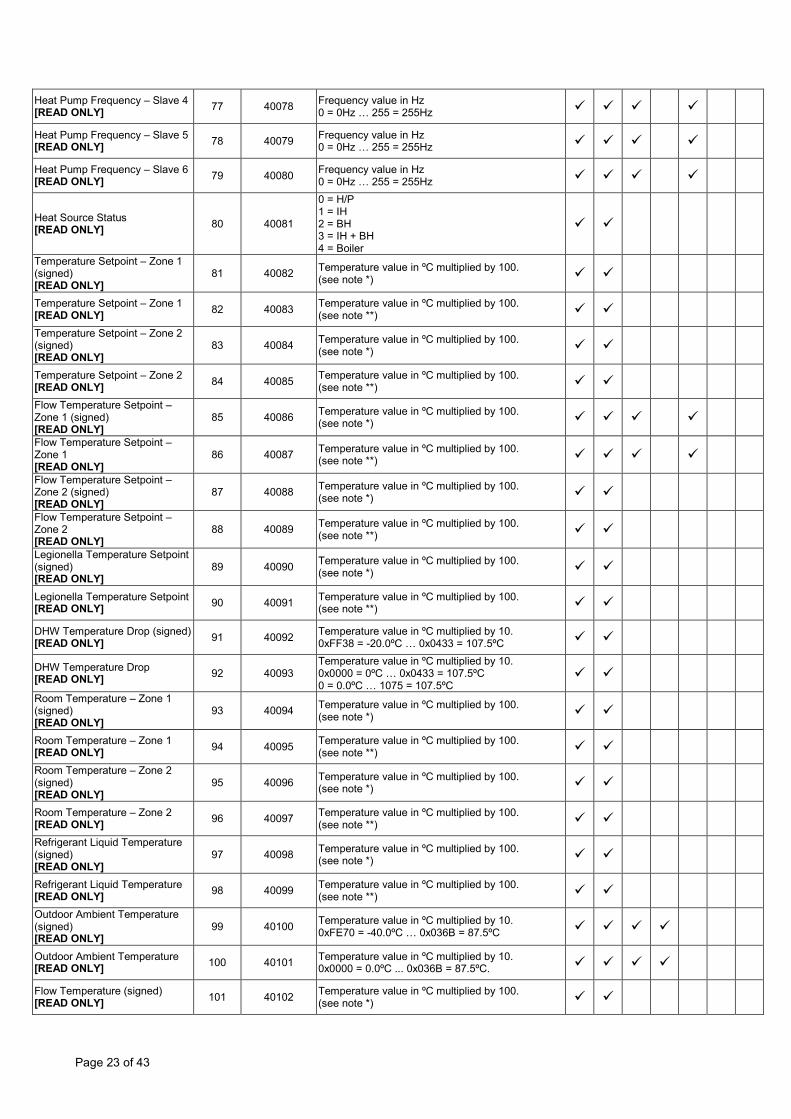
Heat Pump Frequency – Slave 4 [READ ONLY] 77 40078 Frequency value in Hz
0 = 0Hz … 255 = 255Hz
Heat Pump Frequency – Slave 5 [READ ONLY] 78 40079 Frequency value in Hz
0 = 0Hz … 255 = 255Hz
Heat Pump Frequency – Slave 6 [READ ONLY] 79 40080 Frequency value in Hz
0 = 0Hz … 255 = 255Hz
Heat Source Status [READ ONLY] 80 40081
0 = H/P 1 = IH 2 = BH 3 = IH + BH 4 = Boiler
Temperature Setpoint – Zone 1 (signed) [READ ONLY]
81 40082 Temperature value in ºC multiplied by 100. (see note *)
Temperature Setpoint – Zone 1 [READ ONLY] 82 40083 Temperature value in ºC multiplied by 100.
(see note **)
Temperature Setpoint – Zone 2 (signed) [READ ONLY]
83 40084 Temperature value in ºC multiplied by 100. (see note *)
Temperature Setpoint – Zone 2 [READ ONLY] 84 40085 Temperature value in ºC multiplied by 100.
(see note **)
Flow Temperature Setpoint – Zone 1 (signed) [READ ONLY]
85 40086 Temperature value in ºC multiplied by 100. (see note *)
Flow Temperature Setpoint – Zone 1 [READ ONLY]
86 40087 Temperature value in ºC multiplied by 100. (see note **)
Flow Temperature Setpoint – Zone 2 (signed) [READ ONLY]
87 40088 Temperature value in ºC multiplied by 100. (see note *)
Flow Temperature Setpoint – Zone 2 [READ ONLY]
88 40089 Temperature value in ºC multiplied by 100. (see note **)
Legionella Temperature Setpoint (signed) [READ ONLY]
89 40090 Temperature value in ºC multiplied by 100. (see note *)
Legionella Temperature Setpoint [READ ONLY] 90 40091 Temperature value in ºC multiplied by 100.
(see note **)
DHW Temperature Drop (signed) [READ ONLY] 91 40092 Temperature value in ºC multiplied by 10.
0xFF38 = -20.0ºC … 0x0433 = 107.5ºC
DHW Temperature Drop [READ ONLY] 92 40093
Temperature value in ºC multiplied by 10. 0x0000 = 0ºC … 0x0433 = 107.5ºC 0 = 0.0ºC … 1075 = 107.5ºC
Room Temperature – Zone 1 (signed) [READ ONLY]
93 40094 Temperature value in ºC multiplied by 100. (see note *)
Room Temperature – Zone 1 [READ ONLY] 94 40095 Temperature value in ºC multiplied by 100.
(see note **)
Room Temperature – Zone 2 (signed) [READ ONLY]
95 40096 Temperature value in ºC multiplied by 100. (see note *)
Room Temperature – Zone 2 [READ ONLY] 96 40097 Temperature value in ºC multiplied by 100.
(see note **)
Refrigerant Liquid Temperature (signed) [READ ONLY]
97 40098 Temperature value in ºC multiplied by 100. (see note *)
Refrigerant Liquid Temperature [READ ONLY] 98 40099 Temperature value in ºC multiplied by 100.
(see note **)
Outdoor Ambient Temperature (signed) [READ ONLY]
99 40100 Temperature value in ºC multiplied by 10. 0xFE70 = -40.0ºC … 0x036B = 87.5ºC
Outdoor Ambient Temperature [READ ONLY] 100 40101 Temperature value in ºC multiplied by 10.
0x0000 = 0.0ºC ... 0x036B = 87.5ºC.
Flow Temperature (signed) [READ ONLY] 101 40102 Temperature value in ºC multiplied by 100.
(see note *)

Page 24 of 43
Water Outlet Temperature (signed) [READ ONLY]
Temperature value in ºC multiplied by 100. (see note *)
Flow Temperature [READ ONLY]
102 40103
Temperature value in ºC multiplied by 100. (see note **)
Water Outlet Temperature [READ ONLY]
Temperature value in ºC multiplied by 100. (see note **)
Return Temperature (signed) [READ ONLY]
103 40104
Temperature value in ºC multiplied by 100. (see note *)
Water Inlet Temperature (signed) [READ ONLY]
Temperature value in ºC multiplied by 100. (see note *)
Return Temperature [READ ONLY]
104 40105
Temperature value in ºC multiplied by 100. (see note **)
Water Inlet Temperature [READ ONLY]
Temperature value in ºC multiplied by 100. (see note **)
Tank Water Temperature (signed) [READ ONLY]
105 40106 Temperature value in ºC multiplied by 100. (see note *)
Tank Water Temperature [READ ONLY] 106 40107 Temperature value in ºC multiplied by 100.
(see note **)
Flow Temperature – Zone 1 (signed) [READ ONLY] 107 40108
Temperature value in ºC multiplied by 100. (see note *)
External Water Temperature 1 (signed) [READ ONLY]
Temperature value in ºC multiplied by 100. (see note *)
Flow Temperature – Zone 1 [READ ONLY]
108 40109
Temperature value in ºC multiplied by 100. (see note **)
External Water Temperature 1 [READ ONLY]
Temperature value in ºC multiplied by 100. (see note **)
Return Temperature – Zone 1 (signed) [READ ONLY]
109 40110 Temperature value in ºC multiplied by 100. (see note *)
Return Temperature – Zone 1 [READ ONLY] 110 40111 Temperature value in ºC multiplied by 100.
(see note **)
Flow Temperature – Zone 2 (signed) [READ ONLY] 111 40112
Temperature value in ºC multiplied by 100. (see note *)
External Water Temperature 2 (signed) [READ ONLY]
Temperature value in ºC multiplied by 100. (see note *)
Flow Temperature – Zone 2 [READ ONLY]
112 40113
Temperature value in ºC multiplied by 100. (see note **)
External Water Temperature 2 [READ ONLY]
Temperature value in ºC multiplied by 100. (see note **)
Return Temperature – Zone 2 (signed) [READ ONLY]
113 40114 Temperature value in ºC multiplied by 100. (see note *)
Return Temperature – Zone 2 [READ ONLY] 114 40115 Temperature value in ºC multiplied by 100.
(see note **)
Boiler Flow Temperature (signed) [READ ONLY]
115 40116 Temperature value in ºC multiplied by 100. (see note *)
Boiler Flow Temperature [READ ONLY] 116 40117 Temperature value in ºC multiplied by 100.
(see note **)
Boiler Return Temperature (signed) [READ ONLY]
117 40118 Temperature value in ºC multiplied by 100. (see note *)
Boiler Return Temperature [READ ONLY] 118 40119 Temperature value in ºC multiplied by 100.
(see note **)
Room Thermo 1 (IN1) [READ ONLY] 119 40120 0 = OFF, 1 = ON
Page 25 of 43
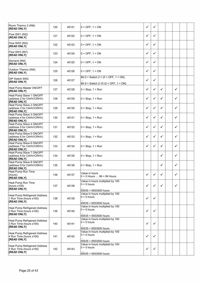
Room Thermo 2 (IN6) [READ ONLY] 120 40121 0 = OFF, 1 = ON
Flow SW1 (IN2) [READ ONLY] 121 40122 0 = OFF, 1 = ON
Flow SW2 (IN3) [READ ONLY] 122 40123 0 = OFF, 1 = ON
Flow SW3 (IN7) [READ ONLY] 123 40124 0 = OFF, 1 = ON
Demand (IN4) [READ ONLY] 124 40125 0 = OFF, 1 = ON
Outdoor Thermo (IN5) [READ ONLY] 125 40126 0 = OFF, 1 = ON
DIP Switch SW2 [READ ONLY] 126 40127
Bit 0 = Switch 2-1 (0 = OFF, 1 = ON) … Bit 9 = Switch 2-10 (0 = OFF, 1 = ON)
Heat Pump Master ON/OFF [READ ONLY] 127 40128 0 = Stop, 1 = Run
Heat Pump Slave 1 ON/OFF (address 2 for CAHV/CRHV) [READ ONLY]
128 40129 0 = Stop, 1 = Run
Heat Pump Slave 2 ON/OFF (address 3 for CAHV/CRHV) [READ ONLY]
129 40130 0 = Stop, 1 = Run
Heat Pump Slave 3 ON/OFF (address 4 for CAHV/CRHV) [READ ONLY]
130 40131 0 = Stop, 1 = Run
Heat Pump Slave 4 ON/OFF (address 5 for CAHV/CRHV) [READ ONLY]
131 40132 0 = Stop, 1 = Run
Heat Pump Slave 5 ON/OFF (address 6 for CAHV/CRHV) [READ ONLY]
132 40133 0 = Stop, 1 = Run
Heat Pump Slave 6 ON/OFF (address 7 for CAHV/CRHV) [READ ONLY]
133 40134 0 = Stop, 1 = Run
Heat Pump Slave 7 ON/OFF (address 8 for CAHV/CRHV) [READ ONLY]
134 40135 0 = Stop, 1 = Run
Heat Pump Slave 8 ON/OFF (address 9 for CAHV/CRHV) [READ ONLY]
135 40136 0 = Stop, 1 = Run
Heat Pump Run Time (hours) [READ ONLY]
136 40137 Value in hours 0 = 0 Hours … 99 = 99 Hours
Heat Pump Run Time (hours x100) [READ ONLY]
137 40138
Value in hours multiplied by 100 0 = 0 hours … 65535 = 6553500 hours
Heat Pump Refrigerant Address 1 Run Time (hours x100) [READ ONLY]
138 40139
Value in hours multiplied by 100 0 = 0 hours … 65535 = 6553500 hours
Heat Pump Refrigerant Address 2 Run Time (hours x100) [READ ONLY]
139 40140
Value in hours multiplied by 100 0 = 0 hours … 65535 = 6553500 hours
Heat Pump Refrigerant Address 3 Run Time (hours x100) [READ ONLY]
140 40141
Value in hours multiplied by 100 0 = 0 hours … 65535 = 6553500 hours
Heat Pump Refrigerant Address 4 Run Time (hours x100) [READ ONLY]
141 40142
Value in hours multiplied by 100 0 = 0 hours … 65535 = 6553500 hours
Heat Pump Refrigerant Address 5 Run Time (hours x100) [READ ONLY]
142 40143
Value in hours multiplied by 100 0 = 0 hours … 65535 = 6553500 hours

Page 26 of 43
Heat Pump Refrigerant Address 6 Run Time (hours x100) [READ ONLY]
143 40144
Value in hours multiplied by 100 0 = 0 hours … 65535 = 6553500 hours
Boiler ON/OFF [READ ONLY]
144 40145 0 = Stop, 1 = Run
External Heater Operation 1 [READ ONLY] 0 = Stop, 1 = Run
Booster Heater 1 ON/OFF [READ ONLY] 145 40146 0 = Stop, 1 = Run
Booster Heater 2 ON/OFF [READ ONLY] 146 40147 0 = Stop, 1 = Run
Booster Heater 2+ ON/OFF [READ ONLY] 147 40148 0 = Stop, 1 = Run
Immersion Heater ON/OFF [READ ONLY] 148 40149 0 = Stop, 1 = Run
Water Pump 1 ON/OFF [READ ONLY] 149 40150 0 = Stop, 1 = Run
Water Pump 2 ON/OFF [READ ONLY] 150 40151 0 = Stop, 1 = Run
Water Pump 3 ON/OFF [READ ONLY] 151 40152 0 = Stop, 1 = Run
3-Way Valve ON/OFF [READ ONLY] 152 40153 0 = Stop, 1 = Run
2-Way Valve 2 ON/OFF [READ ONLY] 153 40154 0 = Stop, 1 = Run
Mixing Valve Step [READ ONLY] 154 40155
0 = Step 0 … 10 = Step 10
Refrigerant 1 Error Code Digit 1 [READ ONLY] 155 40156 (see note ^)
Refrigerant 1 Error Code Digit 2 [READ ONLY] 156 40157 (see note ^^)
Refrigerant 2 Error Code Digit 1 [READ ONLY] 157 40158 (see note ^)
Refrigerant 2 Error Code Digit 2 [READ ONLY] 158 40159 (see note ^^)
Refrigerant 3 Error Code Digit 1 [READ ONLY] 159 40160 (see note ^)
Refrigerant 3 Error Code Digit 2 [READ ONLY] 160 40161 (see note ^^)
Refrigerant 4 Error Code Digit 1 [READ ONLY] 161 40162 (see note ^)
Refrigerant 4 Error Code Digit 2 [READ ONLY] 162 40163 (see note ^^)
Refrigerant 5 Error Code Digit 1 [READ ONLY] 163 40164 (see note ^)
Refrigerant 5 Error Code Digit 2 [READ ONLY] 164 40165 (see note ^^)
Refrigerant 6 Error Code Digit 1 [READ ONLY] 165 40166 (see note ^)
Refrigerant 6 Error Code Digit 2 [READ ONLY] 166 40167 (see note ^^)
Heat Pump Frequency – Slave 7 [READ ONLY] 167 40168 Frequency value in Hz
0 = 0Hz … 255 = 255Hz
Page 27 of 43
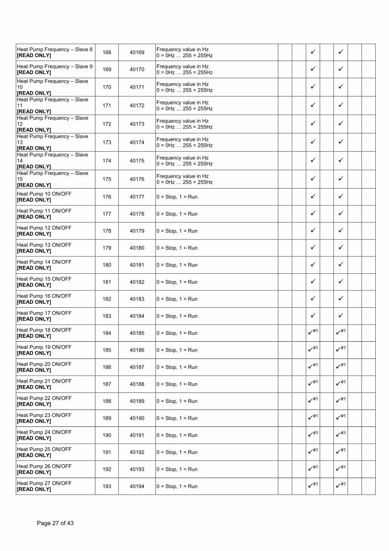
Heat Pump Frequency – Slave 8 [READ ONLY] 168 40169 Frequency value in Hz
0 = 0Hz … 255 = 255Hz
Heat Pump Frequency – Slave 9 [READ ONLY] 169 40170 Frequency value in Hz
0 = 0Hz … 255 = 255Hz
Heat Pump Frequency – Slave 10 [READ ONLY]
170 40171 Frequency value in Hz 0 = 0Hz … 255 = 255Hz
Heat Pump Frequency – Slave 11 [READ ONLY]
171 40172 Frequency value in Hz 0 = 0Hz … 255 = 255Hz
Heat Pump Frequency – Slave 12 [READ ONLY]
172 40173 Frequency value in Hz 0 = 0Hz … 255 = 255Hz
Heat Pump Frequency – Slave 13 [READ ONLY]
173 40174 Frequency value in Hz 0 = 0Hz … 255 = 255Hz
Heat Pump Frequency – Slave 14 [READ ONLY]
174 40175 Frequency value in Hz 0 = 0Hz … 255 = 255Hz
Heat Pump Frequency – Slave 15 [READ ONLY]
175 40176 Frequency value in Hz 0 = 0Hz … 255 = 255Hz
Heat Pump 10 ON/OFF [READ ONLY] 176 40177 0 = Stop, 1 = Run
Heat Pump 11 ON/OFF [READ ONLY] 177 40178 0 = Stop, 1 = Run
Heat Pump 12 ON/OFF [READ ONLY] 178 40179 0 = Stop, 1 = Run
Heat Pump 13 ON/OFF [READ ONLY] 179 40180 0 = Stop, 1 = Run
Heat Pump 14 ON/OFF [READ ONLY] 180 40181 0 = Stop, 1 = Run
Heat Pump 15 ON/OFF [READ ONLY] 181 40182 0 = Stop, 1 = Run
Heat Pump 16 ON/OFF [READ ONLY] 182 40183 0 = Stop, 1 = Run
Heat Pump 17 ON/OFF [READ ONLY] 183 40184 0 = Stop, 1 = Run
Heat Pump 18 ON/OFF [READ ONLY] 184 40185 0 = Stop, 1 = Run #1 #1
Heat Pump 19 ON/OFF [READ ONLY] 185 40186 0 = Stop, 1 = Run #1 #1
Heat Pump 20 ON/OFF [READ ONLY] 186 40187 0 = Stop, 1 = Run #1 #1
Heat Pump 21 ON/OFF [READ ONLY] 187 40188 0 = Stop, 1 = Run #1 #1
Heat Pump 22 ON/OFF [READ ONLY] 188 40189 0 = Stop, 1 = Run #1 #1
Heat Pump 23 ON/OFF [READ ONLY] 189 40190 0 = Stop, 1 = Run #1 #1
Heat Pump 24 ON/OFF [READ ONLY] 190 40191 0 = Stop, 1 = Run #1 #1
Heat Pump 25 ON/OFF [READ ONLY] 191 40192 0 = Stop, 1 = Run #1 #1
Heat Pump 26 ON/OFF [READ ONLY] 192 40193 0 = Stop, 1 = Run #1 #1
Heat Pump 27 ON/OFF [READ ONLY] 193 40194 0 = Stop, 1 = Run #1 #1
Page 28 of 43
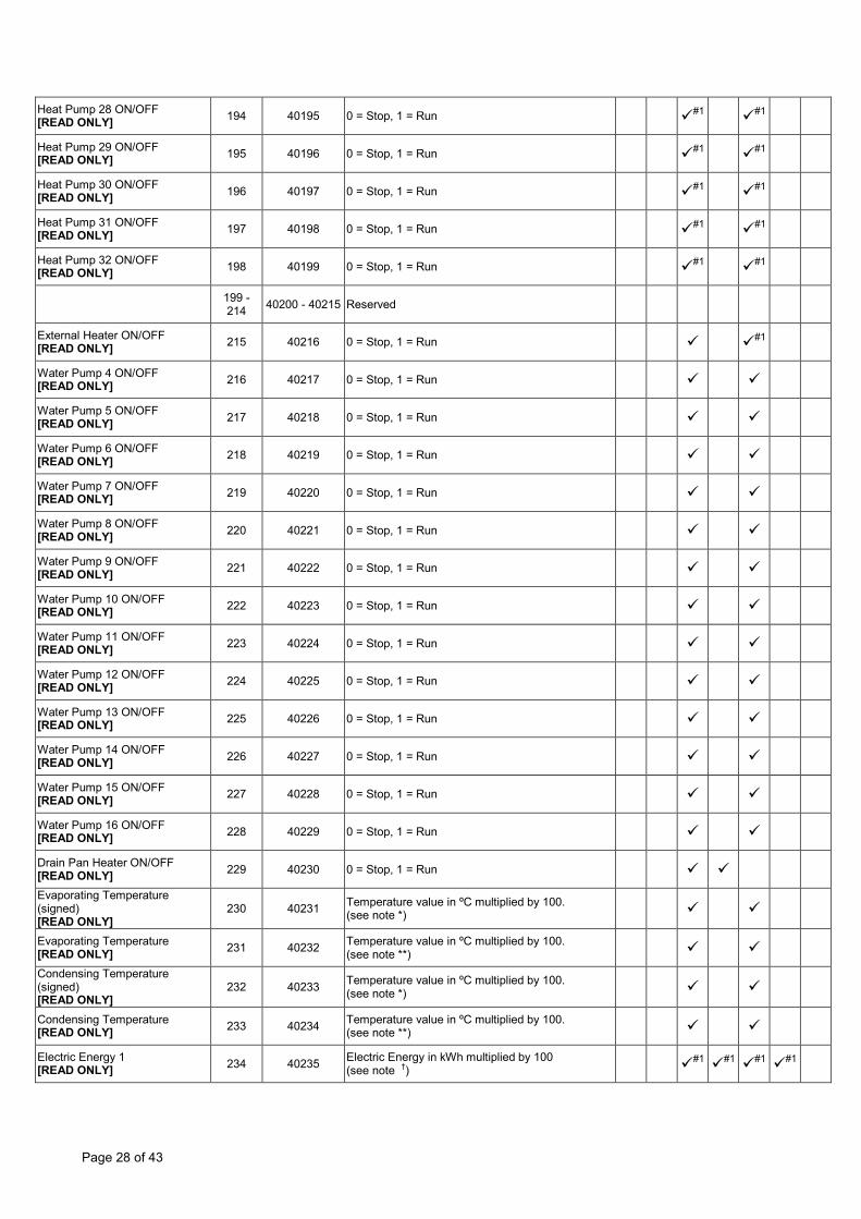
Heat Pump 28 ON/OFF [READ ONLY] 194 40195 0 = Stop, 1 = Run #1 #1
Heat Pump 29 ON/OFF [READ ONLY] 195 40196 0 = Stop, 1 = Run #1 #1
Heat Pump 30 ON/OFF [READ ONLY] 196 40197 0 = Stop, 1 = Run #1 #1
Heat Pump 31 ON/OFF [READ ONLY] 197 40198 0 = Stop, 1 = Run #1 #1
Heat Pump 32 ON/OFF [READ ONLY] 198 40199 0 = Stop, 1 = Run #1 #1
199 - 214 40200 - 40215 Reserved
External Heater ON/OFF [READ ONLY] 215 40216 0 = Stop, 1 = Run #1
Water Pump 4 ON/OFF [READ ONLY] 216 40217 0 = Stop, 1 = Run
Water Pump 5 ON/OFF [READ ONLY] 217 40218 0 = Stop, 1 = Run
Water Pump 6 ON/OFF [READ ONLY] 218 40219 0 = Stop, 1 = Run
Water Pump 7 ON/OFF [READ ONLY] 219 40220 0 = Stop, 1 = Run
Water Pump 8 ON/OFF [READ ONLY] 220 40221 0 = Stop, 1 = Run
Water Pump 9 ON/OFF [READ ONLY] 221 40222 0 = Stop, 1 = Run
Water Pump 10 ON/OFF [READ ONLY] 222 40223 0 = Stop, 1 = Run
Water Pump 11 ON/OFF [READ ONLY] 223 40224 0 = Stop, 1 = Run
Water Pump 12 ON/OFF [READ ONLY] 224 40225 0 = Stop, 1 = Run
Water Pump 13 ON/OFF [READ ONLY] 225 40226 0 = Stop, 1 = Run
Water Pump 14 ON/OFF [READ ONLY] 226 40227 0 = Stop, 1 = Run
Water Pump 15 ON/OFF [READ ONLY] 227 40228 0 = Stop, 1 = Run
Water Pump 16 ON/OFF [READ ONLY] 228 40229 0 = Stop, 1 = Run
Drain Pan Heater ON/OFF [READ ONLY] 229 40230 0 = Stop, 1 = Run
Evaporating Temperature (signed) [READ ONLY]
230 40231 Temperature value in ºC multiplied by 100. (see note *)
Evaporating Temperature [READ ONLY] 231 40232 Temperature value in ºC multiplied by 100.
(see note **)
Condensing Temperature (signed) [READ ONLY]
232 40233 Temperature value in ºC multiplied by 100. (see note *)
Condensing Temperature [READ ONLY] 233 40234 Temperature value in ºC multiplied by 100.
(see note **)
Electric Energy 1 [READ ONLY] 234 40235 Electric Energy in kWh multiplied by 100
(see note †) #1 #1 #1 #1
Page 29 of 43
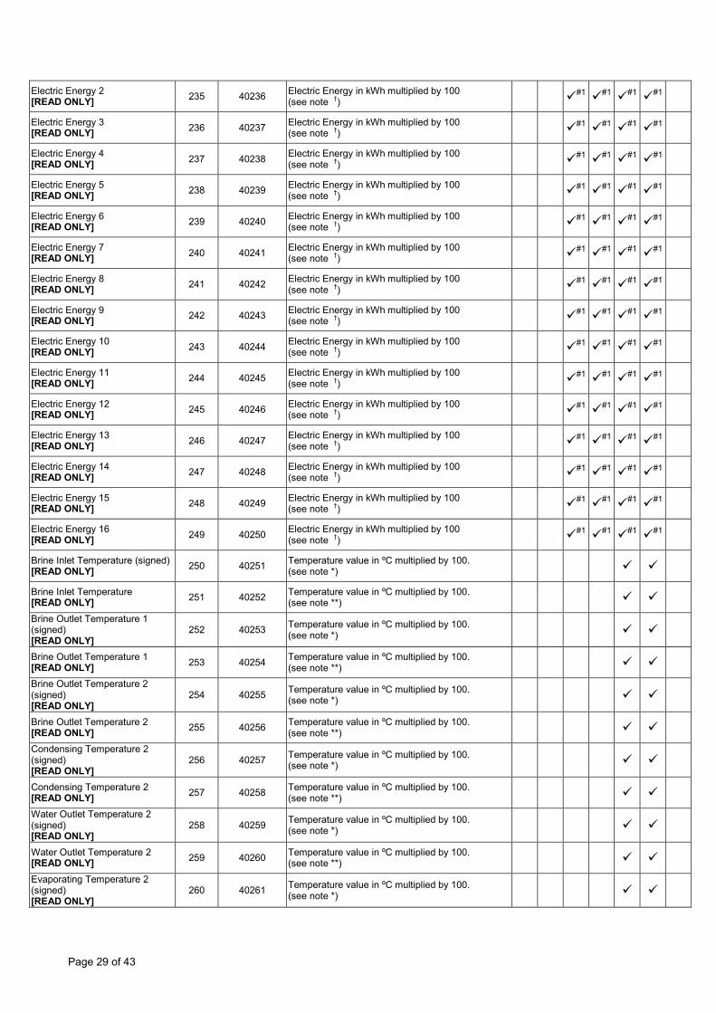
Electric Energy 2 [READ ONLY] 235 40236 Electric Energy in kWh multiplied by 100
(see note †) #1 #1 #1 #1
Electric Energy 3 [READ ONLY] 236 40237 Electric Energy in kWh multiplied by 100
(see note †) #1 #1 #1 #1
Electric Energy 4 [READ ONLY] 237 40238 Electric Energy in kWh multiplied by 100
(see note †) #1 #1 #1 #1
Electric Energy 5 [READ ONLY] 238 40239 Electric Energy in kWh multiplied by 100
(see note †) #1 #1 #1 #1
Electric Energy 6 [READ ONLY] 239 40240 Electric Energy in kWh multiplied by 100
(see note †) #1 #1 #1 #1
Electric Energy 7 [READ ONLY] 240 40241 Electric Energy in kWh multiplied by 100
(see note †) #1 #1 #1 #1
Electric Energy 8 [READ ONLY] 241 40242 Electric Energy in kWh multiplied by 100
(see note †) #1 #1 #1 #1
Electric Energy 9 [READ ONLY] 242 40243 Electric Energy in kWh multiplied by 100
(see note †) #1 #1 #1 #1
Electric Energy 10 [READ ONLY] 243 40244 Electric Energy in kWh multiplied by 100
(see note †) #1 #1 #1 #1
Electric Energy 11 [READ ONLY] 244 40245 Electric Energy in kWh multiplied by 100
(see note †) #1 #1 #1 #1
Electric Energy 12 [READ ONLY] 245 40246 Electric Energy in kWh multiplied by 100
(see note †) #1 #1 #1 #1
Electric Energy 13 [READ ONLY] 246 40247 Electric Energy in kWh multiplied by 100
(see note †) #1 #1 #1 #1
Electric Energy 14 [READ ONLY] 247 40248 Electric Energy in kWh multiplied by 100
(see note †) #1 #1 #1 #1
Electric Energy 15 [READ ONLY] 248 40249 Electric Energy in kWh multiplied by 100
(see note †) #1 #1 #1 #1
Electric Energy 16 [READ ONLY] 249 40250 Electric Energy in kWh multiplied by 100
(see note †) #1 #1 #1 #1
Brine Inlet Temperature (signed) [READ ONLY] 250 40251 Temperature value in ºC multiplied by 100.
(see note *)
Brine Inlet Temperature [READ ONLY] 251 40252 Temperature value in ºC multiplied by 100.
(see note **)
Brine Outlet Temperature 1 (signed) [READ ONLY]
252 40253 Temperature value in ºC multiplied by 100. (see note *)
Brine Outlet Temperature 1 [READ ONLY] 253 40254 Temperature value in ºC multiplied by 100.
(see note **)
Brine Outlet Temperature 2 (signed) [READ ONLY]
254 40255 Temperature value in ºC multiplied by 100. (see note *)
Brine Outlet Temperature 2 [READ ONLY] 255 40256 Temperature value in ºC multiplied by 100.
(see note **)
Condensing Temperature 2 (signed) [READ ONLY]
256 40257 Temperature value in ºC multiplied by 100. (see note *)
Condensing Temperature 2 [READ ONLY] 257 40258 Temperature value in ºC multiplied by 100.
(see note **)
Water Outlet Temperature 2 (signed) [READ ONLY]
258 40259 Temperature value in ºC multiplied by 100. (see note *)
Water Outlet Temperature 2 [READ ONLY] 259 40260 Temperature value in ºC multiplied by 100.
(see note **)
Evaporating Temperature 2 (signed) [READ ONLY]
260 40261 Temperature value in ºC multiplied by 100. (see note *)
Page 30 of 43
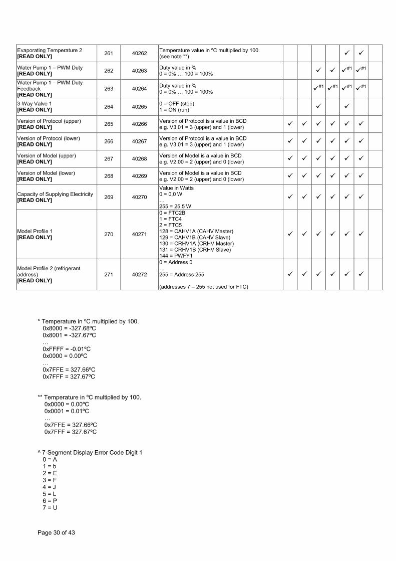
Evaporating Temperature 2 [READ ONLY] 261 40262 Temperature value in ºC multiplied by 100.
(see note **)
Water Pump 1 – PWM Duty [READ ONLY] 262 40263 Duty value in %
0 = 0% … 100 = 100% #1 #1
Water Pump 1 – PWM Duty Feedback [READ ONLY]
263 40264 Duty value in % 0 = 0% … 100 = 100% #1 #1 #1 #1
3-Way Valve 1 [READ ONLY] 264 40265 0 = OFF (stop)
1 = ON (run)
Version of Protocol (upper) [READ ONLY] 265 40266 Version of Protocol is a value in BCD
e.g. V3.01 = 3 (upper) and 1 (lower)
Version of Protocol (lower) [READ ONLY] 266 40267 Version of Protocol is a value in BCD
e.g. V3.01 = 3 (upper) and 1 (lower)
Version of Model (upper) [READ ONLY] 267 40268 Version of Model is a value in BCD
e.g. V2.00 = 2 (upper) and 0 (lower)
Version of Model (lower) [READ ONLY] 268 40269 Version of Model is a value in BCD
e.g. V2.00 = 2 (upper) and 0 (lower)
Capacity of Supplying Electricity [READ ONLY] 269 40270
Value in Watts 0 = 0,0 W … 255 = 25,5 W
Model Profile 1 [READ ONLY] 270 40271
0 = FTC2B 1 = FTC4 2 = FTC5 128 = CAHV1A (CAHV Master) 129 = CAHV1B (CAHV Slave) 130 = CRHV1A (CRHV Master) 131 = CRHV1B (CRHV Slave) 144 = PWFY1
Model Profile 2 (refrigerant address) [READ ONLY]
271 40272
0 = Address 0 … 255 = Address 255 (addresses 7 – 255 not used for FTC)
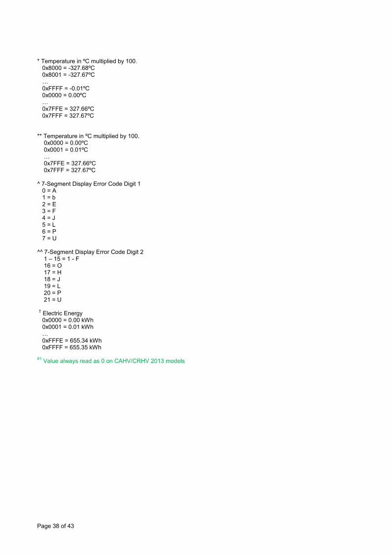
* Temperature in ºC multiplied by 100. 0x8000 = -327.68ºC 0x8001 = -327.67ºC … 0xFFFF = -0.01ºC 0x0000 = 0.00ºC … 0x7FFE = 327.66ºC 0x7FFF = 327.67ºC ** Temperature in ºC multiplied by 100. 0x0000 = 0.00ºC 0x0001 = 0.01ºC … 0x7FFE = 327.66ºC 0x7FFF = 327.67ºC ^ 7-Segment Display Error Code Digit 1 0 = A 1 = b 2 = E 3 = F 4 = J 5 = L 6 = P 7 = U

Page 31 of 43
^^ 7-Segment Display Error Code Digit 2 1 – 15 = 1 - F 16 = O 17 = H 18 = J 19 = L 20 = P 21 = U † Electric Energy 0x0000 = 0.00 kWh 0x0001 = 0.01 kWh … 0xFFFE = 655.34 kWh 0xFFFF = 655.35 kWh
†† MRC Prohibit command must NOT be written to Shizuoka designed models #1 Value always read as 0 on CAHV/CRHV 2013 models #2 Value always read as 0 on CAHV/CRHV 2013 models #3 Value always read as 0 on CAHV/CRHV 2013 models #4 Stop and Cooling modes not supported on CAHV 2013 models #5 Stop, Cooling and Legionella modes not supported on CRHV 2013 models #6 This value is read only on FTC4 models #7 Bit 4 not supported on CAHV/CRHV 2013 models #8 This setting is not supported on CAHV/CRHV 2013 models #9 Range is -30..+50ºC for CRHV/CAHV models #10 Range is 0..+50ºC for CRHV/CAHV models #11 Range is +30..+65ºC for CAHV models #12 Range is +25..+65ºC for CRHV models
Page 32 of 43
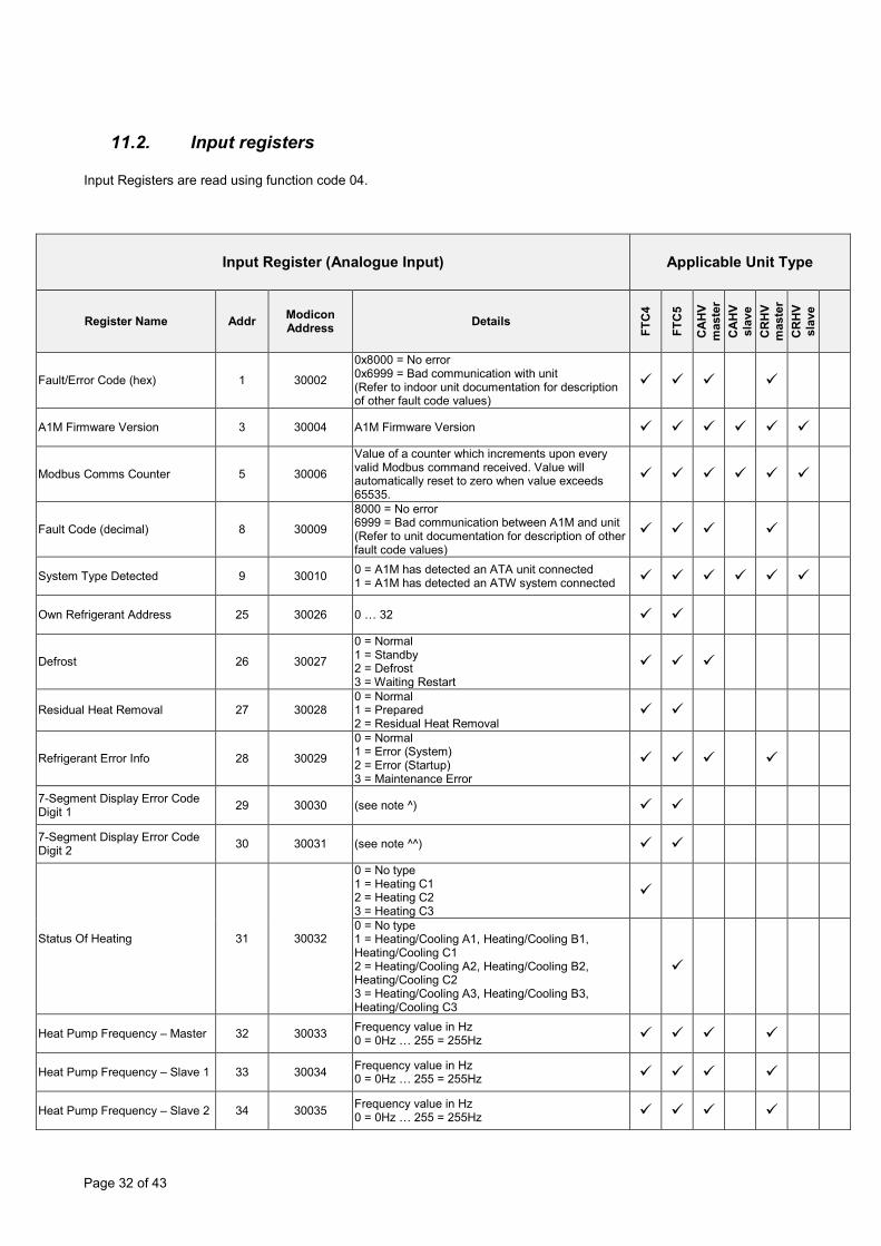
11.2. Input registers Input Registers are read using function code 04.
Input Register (Analogue Input) Applicable Unit Type
Register Name Addr Modicon Address Details
FTC
4
FTC
5
CA
HV
mas
ter
CA
HV
slav
e C
RH
V m
aste
r C
RH
V sl
ave
Fault/Error Code (hex) 1 30002
0x8000 = No error 0x6999 = Bad communication with unit (Refer to indoor unit documentation for description of other fault code values)
A1M Firmware Version 3 30004 A1M Firmware Version
Modbus Comms Counter 5 30006
Value of a counter which increments upon every valid Modbus command received. Value will automatically reset to zero when value exceeds 65535.
Fault Code (decimal) 8 30009
8000 = No error 6999 = Bad communication between A1M and unit (Refer to unit documentation for description of other fault code values)
System Type Detected 9 30010 0 = A1M has detected an ATA unit connected 1 = A1M has detected an ATW system connected
Own Refrigerant Address 25 30026 0 … 32
Defrost 26 30027
0 = Normal 1 = Standby 2 = Defrost 3 = Waiting Restart
Residual Heat Removal 27 30028 0 = Normal 1 = Prepared 2 = Residual Heat Removal
Refrigerant Error Info 28 30029
0 = Normal 1 = Error (System) 2 = Error (Startup) 3 = Maintenance Error
7-Segment Display Error Code Digit 1 29 30030 (see note ^)
7-Segment Display Error Code Digit 2 30 30031 (see note ^^)
Status Of Heating 31 30032
0 = No type 1 = Heating C1 2 = Heating C2 3 = Heating C3
0 = No type 1 = Heating/Cooling A1, Heating/Cooling B1, Heating/Cooling C1 2 = Heating/Cooling A2, Heating/Cooling B2, Heating/Cooling C2 3 = Heating/Cooling A3, Heating/Cooling B3, Heating/Cooling C3
Heat Pump Frequency – Master 32 30033 Frequency value in Hz 0 = 0Hz … 255 = 255Hz
Heat Pump Frequency – Slave 1 33 30034 Frequency value in Hz 0 = 0Hz … 255 = 255Hz
Heat Pump Frequency – Slave 2 34 30035 Frequency value in Hz 0 = 0Hz … 255 = 255Hz

Page 33 of 43
Heat Pump Frequency – Slave 3 35 30036 Frequency value in Hz 0 = 0Hz … 255 = 255Hz
Heat Pump Frequency – Slave 4 36 30037 Frequency value in Hz 0 = 0Hz … 255 = 255Hz
Heat Pump Frequency – Slave 5 37 30038 Frequency value in Hz 0 = 0Hz … 255 = 255Hz
Heat Pump Frequency – Slave 6 38 30039 Frequency value in Hz 0 = 0Hz … 255 = 255Hz
Heat Source Status 39 30040
0 = H/P 1 = IH 2 = BH 3 = IH + BH 4 = Boiler
Temperature Setpoint – Zone 1 (signed) 40 30041 Temperature value in ºC multiplied by 100.
(see note *)
Temperature Setpoint – Zone 1 41 30042 Temperature value in ºC multiplied by 100. (see note **)
Temperature Setpoint – Zone 2 (signed) 42 30043 Temperature value in ºC multiplied by 100.
(see note *)
Temperature Setpoint – Zone 2 43 30044 Temperature value in ºC multiplied by 100. (see note **)
Flow Temperature Setpoint – Zone 1 (signed) 44 30045 Temperature value in ºC multiplied by 100.
(see note *)
Flow Temperature Setpoint – Zone 1 45 30046 Temperature value in ºC multiplied by 100.
(see note **)
Flow Temperature Setpoint – Zone 2 (signed) 46 30047 Temperature value in ºC multiplied by 100.
(see note *)
Flow Temperature Setpoint – Zone 2 47 30048 Temperature value in ºC multiplied by 100.
(see note **)
Legionella Temperature Setpoint (signed) 48 30049 Temperature value in ºC multiplied by 100.
(see note *)
Legionella Temperature Setpoint 49 30050 Temperature value in ºC multiplied by 100. (see note **)
DHW Temperature Drop (signed) 50 30051 Temperature value in ºC multiplied by 10. 0xFF38 = -20.0ºC … 0x0433 = 107.5ºC
DHW Temperature Drop 51 30052 Temperature value in ºC multiplied by 10. 0x0000 = 0ºC … 0x0433 = 107.5ºC 0 = 0.0ºC … 1075 = 107.5ºC
Room Temperature – Zone 1 (signed) 52 30053 Temperature value in ºC multiplied by 100.
(see note *)
Room Temperature – Zone 1 53 30054 Temperature value in ºC multiplied by 100. (see note **)
Room Temperature – Zone 2 (signed) 54 30055 Temperature value in ºC multiplied by 100.
(see note *)
Room Temperature – Zone 2 55 30056 Temperature value in ºC multiplied by 100. (see note **)
Refrigerant Liquid Temperature (signed) 56 30057 Temperature value in ºC multiplied by 100.
(see note *)
Refrigerant Liquid Temperature 57 30058 Temperature value in ºC multiplied by 100. (see note **)
Outdoor Ambient Temperature (signed) 58 30059 Temperature value in ºC multiplied by 10.
0xFE70 = -40.0ºC … 0x036B = 87.5ºC
Outdoor Ambient Temperature 59 30060 Temperature value in ºC multiplied by 10. 0x0000 = 0.0ºC ... 0x036B = 87.5ºC.
Flow Temperature (signed) 60 30061 Temperature value in ºC multiplied by 100. (see note *)

Page 34 of 43
Water Outlet Temperature (signed)
Temperature value in ºC multiplied by 100. (see note *)
Flow Temperature 61 30062
Temperature value in ºC multiplied by 100. (see note **)
Water Outlet Temperature Temperature value in ºC multiplied by 100. (see note **)
Return Temperature (signed) 62 30063
Temperature value in ºC multiplied by 100. (see note *)
Water Inlet Temperature (signed) Temperature value in ºC multiplied by 100. (see note *)
Return Temperature 63 30064
Temperature value in ºC multiplied by 100. (see note **)
Water Inlet Temperature Temperature value in ºC multiplied by 100. (see note **)
Tank Water Temperature (signed) 64 30065 Temperature value in ºC multiplied by 100.
(see note *)
Tank Water Temperature 65 30066 Temperature value in ºC multiplied by 100. (see note **)
Flow Temperature – Zone 1 (signed)
66 30067
Temperature value in ºC multiplied by 100. (see note *)
External Water Temperature 1 (signed)
Temperature value in ºC multiplied by 100. (see note *)
Flow Temperature – Zone 1 67 30068
Temperature value in ºC multiplied by 100. (see note **)
External Water Temperature 1 Temperature value in ºC multiplied by 100. (see note **)
Return Temperature – Zone 1 (signed) 68 30069 Temperature value in ºC multiplied by 100.
(see note *)
Return Temperature – Zone 1 69 30070 Temperature value in ºC multiplied by 100. (see note **)
Flow Temperature – Zone 2 (signed)
70 30071
Temperature value in ºC multiplied by 100. (see note *)
External Water Temperature 2 (signed)
Temperature value in ºC multiplied by 100. (see note *)
Flow Temperature – Zone 2 71 30072
Temperature value in ºC multiplied by 100. (see note **)
External Water Temperature 2 Temperature value in ºC multiplied by 100. (see note **)
Return Temperature – Zone 2 (signed) 72 30073 Temperature value in ºC multiplied by 100.
(see note *)
Return Temperature – Zone 2 73 30074 Temperature value in ºC multiplied by 100. (see note **)
Boiler Flow Temperature (signed) 74 30075 Temperature value in ºC multiplied by 100.
(see note *)
Boiler Flow Temperature 75 30076 Temperature value in ºC multiplied by 100. (see note **)
Boiler Return Temperature (signed) 76 30077 Temperature value in ºC multiplied by 100.
(see note *)
Boiler Return Temperature 77 30078 Temperature value in ºC multiplied by 100. (see note **)
DIP Switch SW2 78 30079 Bit 0 = Switch 2-1 (0 = OFF, 1 = ON) … Bit 9 = Switch 2-10 (0 = OFF, 1 = ON)
Heat Pump Run Time (hours) 79 30080 Value in hours
0 = 0 Hours … 99 = 99 Hours
Page 35 of 43
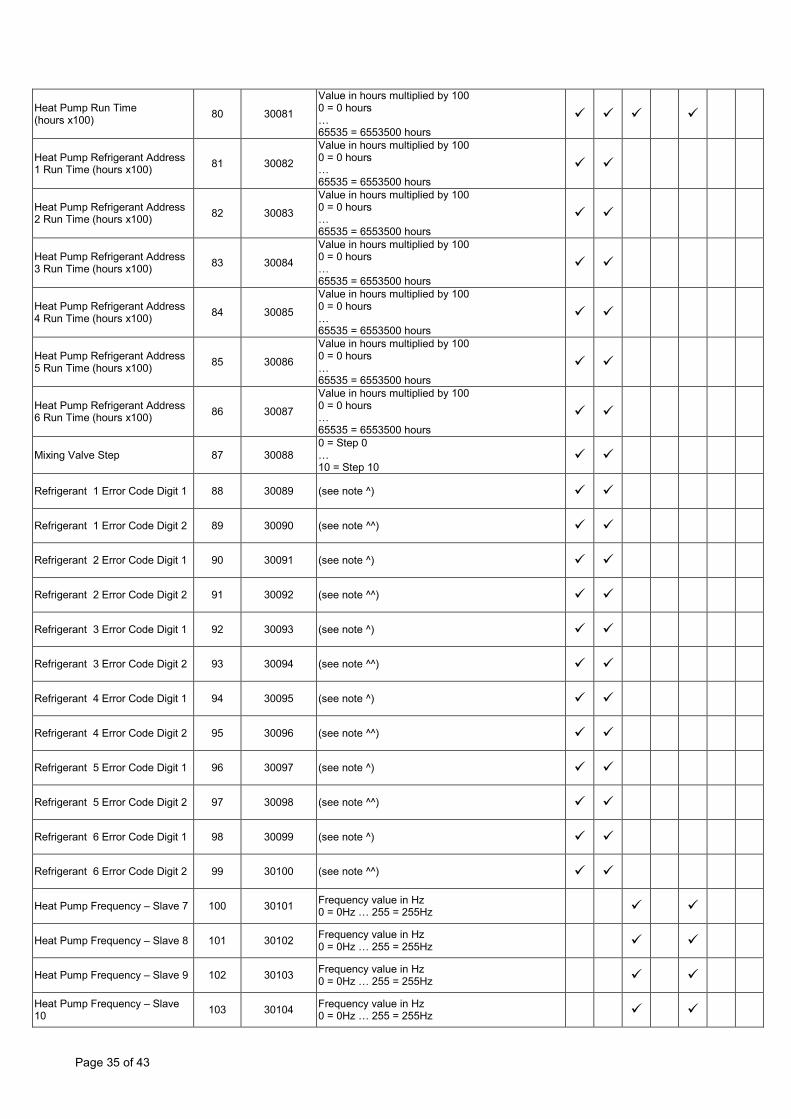
Heat Pump Run Time (hours x100) 80 30081
Value in hours multiplied by 100 0 = 0 hours … 65535 = 6553500 hours
Heat Pump Refrigerant Address 1 Run Time (hours x100) 81 30082
Value in hours multiplied by 100 0 = 0 hours … 65535 = 6553500 hours
Heat Pump Refrigerant Address 2 Run Time (hours x100) 82 30083
Value in hours multiplied by 100 0 = 0 hours … 65535 = 6553500 hours
Heat Pump Refrigerant Address 3 Run Time (hours x100) 83 30084
Value in hours multiplied by 100 0 = 0 hours … 65535 = 6553500 hours
Heat Pump Refrigerant Address 4 Run Time (hours x100) 84 30085
Value in hours multiplied by 100 0 = 0 hours … 65535 = 6553500 hours
Heat Pump Refrigerant Address 5 Run Time (hours x100) 85 30086
Value in hours multiplied by 100 0 = 0 hours … 65535 = 6553500 hours
Heat Pump Refrigerant Address 6 Run Time (hours x100) 86 30087
Value in hours multiplied by 100 0 = 0 hours … 65535 = 6553500 hours
Mixing Valve Step 87 30088 0 = Step 0 … 10 = Step 10
Refrigerant 1 Error Code Digit 1 88 30089 (see note ^)
Refrigerant 1 Error Code Digit 2 89 30090 (see note ^^)
Refrigerant 2 Error Code Digit 1 90 30091 (see note ^)
Refrigerant 2 Error Code Digit 2 91 30092 (see note ^^)
Refrigerant 3 Error Code Digit 1 92 30093 (see note ^)
Refrigerant 3 Error Code Digit 2 93 30094 (see note ^^)
Refrigerant 4 Error Code Digit 1 94 30095 (see note ^)
Refrigerant 4 Error Code Digit 2 95 30096 (see note ^^)
Refrigerant 5 Error Code Digit 1 96 30097 (see note ^)
Refrigerant 5 Error Code Digit 2 97 30098 (see note ^^)
Refrigerant 6 Error Code Digit 1 98 30099 (see note ^)
Refrigerant 6 Error Code Digit 2 99 30100 (see note ^^)
Heat Pump Frequency – Slave 7 100 30101 Frequency value in Hz 0 = 0Hz … 255 = 255Hz
Heat Pump Frequency – Slave 8 101 30102 Frequency value in Hz 0 = 0Hz … 255 = 255Hz
Heat Pump Frequency – Slave 9 102 30103 Frequency value in Hz 0 = 0Hz … 255 = 255Hz
Heat Pump Frequency – Slave 10 103 30104 Frequency value in Hz
0 = 0Hz … 255 = 255Hz

Page 36 of 43
Heat Pump Frequency – Slave 11 104 30105 Frequency value in Hz
0 = 0Hz … 255 = 255Hz
Heat Pump Frequency – Slave 12 105 30106 Frequency value in Hz
0 = 0Hz … 255 = 255Hz
Heat Pump Frequency – Slave 13 106 30107 Frequency value in Hz
0 = 0Hz … 255 = 255Hz
Heat Pump Frequency – Slave 14 107 30108 Frequency value in Hz
0 = 0Hz … 255 = 255Hz
Heat Pump Frequency – Slave 15 108 30109 Frequency value in Hz
0 = 0Hz … 255 = 255Hz
Evaporating Temperature (signed) 109 30110 Temperature value in ºC multiplied by 100.
(see note *)
Evaporating Temperature 110 30111 Temperature value in ºC multiplied by 100. (see note **)
Condensing Temperature (signed) 111 30112 Temperature value in ºC multiplied by 100.
(see note *)
Condensing Temperature 112 30113 Temperature value in ºC multiplied by 100. (see note **)
Electric Energy 1 113 30114 Electric Energy in kWh multiplied by 100 (see note †) #1 #1 #1 #1
Electric Energy 2 114 30115 Electric Energy in kWh multiplied by 100 (see note †) #1 #1 #1 #1
Electric Energy 3 115 30116 Electric Energy in kWh multiplied by 100 (see note †) #1 #1 #1 #1
Electric Energy 4 116 30117 Electric Energy in kWh multiplied by 100 (see note †) #1 #1 #1 #1
Electric Energy 5 117 30118 Electric Energy in kWh multiplied by 100 (see note †) #1 #1 #1 #1
Electric Energy 6 118 30119 Electric Energy in kWh multiplied by 100 (see note †) #1 #1 #1 #1
Electric Energy 7 119 30120 Electric Energy in kWh multiplied by 100 (see note †) #1 #1 #1 #1
Electric Energy 8 120 30121 Electric Energy in kWh multiplied by 100 (see note †) #1 #1 #1 #1
Electric Energy 9 121 30122 Electric Energy in kWh multiplied by 100 (see note †) #1 #1 #1 #1
Electric Energy 10 122 30123 Electric Energy in kWh multiplied by 100 (see note †) #1 #1 #1 #1
Electric Energy 11 123 30124 Electric Energy in kWh multiplied by 100 (see note †) #1 #1 #1 #1
Electric Energy 12 124 30125 Electric Energy in kWh multiplied by 100 (see note †) #1 #1 #1 #1
Electric Energy 13 125 30126 Electric Energy in kWh multiplied by 100 (see note †) #1 #1 #1 #1
Electric Energy 14 126 30127 Electric Energy in kWh multiplied by 100 (see note †) #1 #1 #1 #1
Electric Energy 15 127 30128 Electric Energy in kWh multiplied by 100 (see note †) #1 #1 #1 #1
Electric Energy 16 128 30129 Electric Energy in kWh multiplied by 100 (see note †) #1 #1 #1 #1
Brine Inlet Temperature (signed) 129 30130 Temperature value in ºC multiplied by 100. (see note *)
Brine Inlet Temperature 130 30131 Temperature value in ºC multiplied by 100. (see note **)
Page 37 of 43
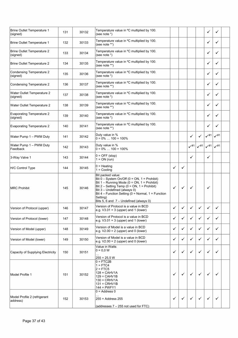
Brine Outlet Temperature 1 (signed) 131 30132 Temperature value in ºC multiplied by 100.
(see note *)
Brine Outlet Temperature 1 132 30133 Temperature value in ºC multiplied by 100. (see note **)
Brine Outlet Temperature 2 (signed) 133 30134 Temperature value in ºC multiplied by 100.
(see note *)
Brine Outlet Temperature 2 134 30135 Temperature value in ºC multiplied by 100. (see note **)
Condensing Temperature 2 (signed) 135 30136 Temperature value in ºC multiplied by 100.
(see note *)
Condensing Temperature 2 136 30137 Temperature value in ºC multiplied by 100. (see note **)
Water Outlet Temperature 2 (signed) 137 30138 Temperature value in ºC multiplied by 100.
(see note *)
Water Outlet Temperature 2 138 30139 Temperature value in ºC multiplied by 100. (see note **)
Evaporating Temperature 2 (signed) 139 30140 Temperature value in ºC multiplied by 100.
(see note *)
Evaporating Temperature 2 140 30141 Temperature value in ºC multiplied by 100. (see note **)
Water Pump 1 – PWM Duty 141 30142 Duty value in % 0 = 0% … 100 = 100% #1 #1
Water Pump 1 – PWM Duty Feedback 142 30143 Duty value in %
0 = 0% … 100 = 100% #1 #1 #1 #1
3-Way Valve 1 143 30144 0 = OFF (stop) 1 = ON (run)
H/C Control Type 144 30145 0 = Heating 1 = Cooling
MRC Prohibit 145 30146
Bit packed value: Bit 0 – System On/Off (0 = ON, 1 = Prohibit) Bit 1 – Running Mode (0 = ON, 1 = Prohibit) Bit 2 – Setting Temp (0 = ON, 1 = Prohibit) Bit 3 – Undefined (always 0) Bit 4 – Function Setting (0 = Normal, 1 = Function Setting) Bits 5, 6 and 7 – Undefined (always 0)
Version of Protocol (upper) 146 30147 Version of Protocol is a value in BCD e.g. V3.01 = 3 (upper) and 1 (lower)
Version of Protocol (lower) 147 30148 Version of Protocol is a value in BCD e.g. V3.01 = 3 (upper) and 1 (lower)
Version of Model (upper) 148 30149 Version of Model is a value in BCD e.g. V2.00 = 2 (upper) and 0 (lower)
Version of Model (lower) 149 30150 Version of Model is a value in BCD e.g. V2.00 = 2 (upper) and 0 (lower)
Capacity of Supplying Electricity 150 30151
Value in Watts 0 = 0,0 W … 255 = 25,5 W
Model Profile 1 151 30152
0 = FTC2B 1 = FTC4 2 = FTC5 128 = CAHV1A 129 = CAHV1B 130 = CRHV1A 131 = CRHV1B 144 = PWFY1
Model Profile 2 (refrigerant address) 152 30153
0 = Address 0 … 255 = Address 255 (addresses 7 – 255 not used for FTC)
Page 38 of 43
* Temperature in ºC multiplied by 100. 0x8000 = -327.68ºC 0x8001 = -327.67ºC … 0xFFFF = -0.01ºC 0x0000 = 0.00ºC … 0x7FFE = 327.66ºC 0x7FFF = 327.67ºC ** Temperature in ºC multiplied by 100. 0x0000 = 0.00ºC 0x0001 = 0.01ºC … 0x7FFE = 327.66ºC 0x7FFF = 327.67ºC ^ 7-Segment Display Error Code Digit 1 0 = A 1 = b 2 = E 3 = F 4 = J 5 = L 6 = P 7 = U ^^ 7-Segment Display Error Code Digit 2 1 – 15 = 1 - F 16 = O 17 = H 18 = J 19 = L 20 = P 21 = U † Electric Energy 0x0000 = 0.00 kWh 0x0001 = 0.01 kWh … 0xFFFE = 655.34 kWh 0xFFFF = 655.35 kWh #1 Value always read as 0 on CAHV/CRHV 2013 models
Page 39 of 43
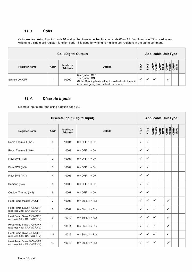
11.3. Coils Coils are read using function code 01 and written to using either function code 05 or 15. Function code 05 is used when writing to a single coil register, function code 15 is used for writing to multiple coil registers in the same command.
Coil (Digital Output) Applicable Unit Type
Register Name Addr Modicon Address Details
FTC
4
FTC
5
CA
HV
mas
ter
CA
HV
slav
e C
RH
V m
aste
r C
RH
V sl
ave
System ON/OFF 1 00002
0 = System OFF 1 = System ON (Note: Reading back value 1 could indicate the unit is in Emergency Run or Test Run mode)
11.4. Discrete Inputs Discrete Inputs are read using function code 02.
Discrete Input (Digital Input) Applicable Unit Type
Register Name Addr Modicon Address Details
FTC
4
FTC
5
CA
HV
mas
ter
CA
HV
slav
e C
RH
V m
aste
r C
RH
V sl
ave
Room Thermo 1 (IN1) 0 10001 0 = OFF, 1 = ON
Room Thermo 2 (IN6) 1 10002 0 = OFF, 1 = ON
Flow SW1 (IN2) 2 10003 0 = OFF, 1 = ON
Flow SW2 (IN3) 3 10004 0 = OFF, 1 = ON
Flow SW3 (IN7) 4 10005 0 = OFF, 1 = ON
Demand (IN4) 5 10006 0 = OFF, 1 = ON
Outdoor Thermo (IN5) 6 10007 0 = OFF, 1 = ON
Heat Pump Master ON/OFF 7 10008 0 = Stop, 1 = Run
Heat Pump Slave 1 ON/OFF (address 2 for CAHV/CRHV) 8 10009 0 = Stop, 1 = Run
Heat Pump Slave 2 ON/OFF (address 3 for CAHV/CRHV) 9 10010 0 = Stop, 1 = Run
Heat Pump Slave 3 ON/OFF (address 4 for CAHV/CRHV) 10 10011 0 = Stop, 1 = Run
Heat Pump Slave 4 ON/OFF (address 5 for CAHV/CRHV) 11 10012 0 = Stop, 1 = Run
Heat Pump Slave 5 ON/OFF (address 6 for CAHV/CRHV) 12 10013 0 = Stop, 1 = Run
Page 40 of 43
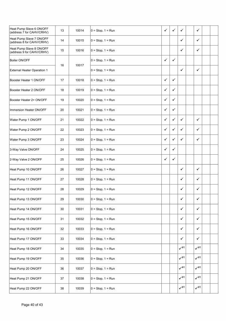
Heat Pump Slave 6 ON/OFF (address 7 for CAHV/CRHV) 13 10014 0 = Stop, 1 = Run
Heat Pump Slave 7 ON/OFF (address 8 for CAHV/CRHV) 14 10015 0 = Stop, 1 = Run
Heat Pump Slave 8 ON/OFF (address 9 for CAHV/CRHV) 15 10016 0 = Stop, 1 = Run
Boiler ON/OFF 16 10017
0 = Stop, 1 = Run
External Heater Operation 1 0 = Stop, 1 = Run
Booster Heater 1 ON/OFF 17 10018 0 = Stop, 1 = Run
Booster Heater 2 ON/OFF 18 10019 0 = Stop, 1 = Run
Booster Heater 2+ ON/OFF 19 10020 0 = Stop, 1 = Run
Immersion Heater ON/OFF 20 10021 0 = Stop, 1 = Run
Water Pump 1 ON/OFF 21 10022 0 = Stop, 1 = Run
Water Pump 2 ON/OFF 22 10023 0 = Stop, 1 = Run
Water Pump 3 ON/OFF 23 10024 0 = Stop, 1 = Run
3-Way Valve ON/OFF 24 10025 0 = Stop, 1 = Run
2-Way Valve 2 ON/OFF 25 10026 0 = Stop, 1 = Run
Heat Pump 10 ON/OFF 26 10027 0 = Stop, 1 = Run
Heat Pump 11 ON/OFF 27 10028 0 = Stop, 1 = Run
Heat Pump 12 ON/OFF 28 10029 0 = Stop, 1 = Run
Heat Pump 13 ON/OFF 29 10030 0 = Stop, 1 = Run
Heat Pump 14 ON/OFF 30 10031 0 = Stop, 1 = Run
Heat Pump 15 ON/OFF 31 10032 0 = Stop, 1 = Run
Heat Pump 16 ON/OFF 32 10033 0 = Stop, 1 = Run
Heat Pump 17 ON/OFF 33 10034 0 = Stop, 1 = Run
Heat Pump 18 ON/OFF 34 10035 0 = Stop, 1 = Run #1 #1
Heat Pump 19 ON/OFF 35 10036 0 = Stop, 1 = Run #1 #1
Heat Pump 20 ON/OFF 36 10037 0 = Stop, 1 = Run #1 #1
Heat Pump 21 ON/OFF 37 10038 0 = Stop, 1 = Run #1 #1
Heat Pump 22 ON/OFF 38 10039 0 = Stop, 1 = Run #1 #1

Page 41 of 43
Heat Pump 23 ON/OFF 39 10040 0 = Stop, 1 = Run #1 #1
Heat Pump 24 ON/OFF 40 10041 0 = Stop, 1 = Run #1 #1
Heat Pump 25 ON/OFF 41 10042 0 = Stop, 1 = Run #1 #1
Heat Pump 26 ON/OFF 42 10043 0 = Stop, 1 = Run #1 #1
Heat Pump 27 ON/OFF 43 10044 0 = Stop, 1 = Run #1 #1
Heat Pump 28 ON/OFF 44 10045 0 = Stop, 1 = Run #1 #1
Heat Pump 29 ON/OFF 45 10046 0 = Stop, 1 = Run #1 #1
Heat Pump 30 ON/OFF 46 10047 0 = Stop, 1 = Run #1 #1
Heat Pump 31 ON/OFF 47 10048 0 = Stop, 1 = Run #1 #1
Heat Pump 32 ON/OFF 48 10049 0 = Stop, 1 = Run #1 #1
49 - 64 10050 - 10065 Reserved
External Heater ON/OFF 65 10066 0 = Stop, 1 = Run #1
Water Pump 4 ON/OFF 66 10067 0 = Stop, 1 = Run
Water Pump 5 ON/OFF 67 10068 0 = Stop, 1 = Run
Water Pump 6 ON/OFF 68 10069 0 = Stop, 1 = Run
Water Pump 7 ON/OFF 69 10070 0 = Stop, 1 = Run
Water Pump 8 ON/OFF 70 10071 0 = Stop, 1 = Run
Water Pump 9 ON/OFF 71 10072 0 = Stop, 1 = Run
Water Pump 10 ON/OFF 72 10073 0 = Stop, 1 = Run
Water Pump 11 ON/OFF 73 10074 0 = Stop, 1 = Run
Water Pump 12 ON/OFF 74 10075 0 = Stop, 1 = Run
Water Pump 13 ON/OFF 75 10076 0 = Stop, 1 = Run
Water Pump 14 ON/OFF 76 10077 0 = Stop, 1 = Run
Water Pump 15 ON/OFF 77 10078 0 = Stop, 1 = Run
Water Pump 16 ON/OFF 78 10079 0 = Stop, 1 = Run
Drain Pan Heater ON/OFF 79 10080 0 = Stop, 1 = Run
#1 Value always read as 0 on CAHV/CRHV 2013 models

Page 42 of 43
Appendix A – Compatible Air-To-Air units UK Models M Series MSZ-SF25/35/50VE MSZ-GF60/71VE MSZ-EF25/35/50VES/VEW/VEB MSZ-FH25/35VE MSZ-FD25/35VA MSZ-GE22/25/35/50/60/71VA MSZ-GC22/25/35VA MSZ-GB50VA MSZ-GA22/25/35/50/60/71VA MFZ-KA25/35/50VA Mr Slim PCA-RP50/60/71/100/125/140KAQ PEAD-RP35/50/60/71/100/125/140JAQ PEAD-RP35/50/60/71/100/125/140EA/EA2 PEA-RP200/250GAQ PKA-RP35/50HAL PKA-RP60/71/100KAL PLA-ZRP35/50/60/71/100/125/140BA/BA2 PLA-RP35/50/60/71/100/125/140BA/BA2/BA3 PLA-RP35/50/60/71/100/125/140AA/AA2 PSA-RP71/100/125/140KA PSA-RP71/100/125/140GA SEZ-KD25/35/50/60/71VAQ SEZ-KA35/50/60/71VA SLZ-KA25/35/50VAQ SLZ-KA25/35/50VA Models Not Supported: MSZ-HJ25/35VA MSZ-HC25/35VA/VAB PCA-RP71/125HA/HAQ PEA-RP400/500GAQ
Page 43 of 43
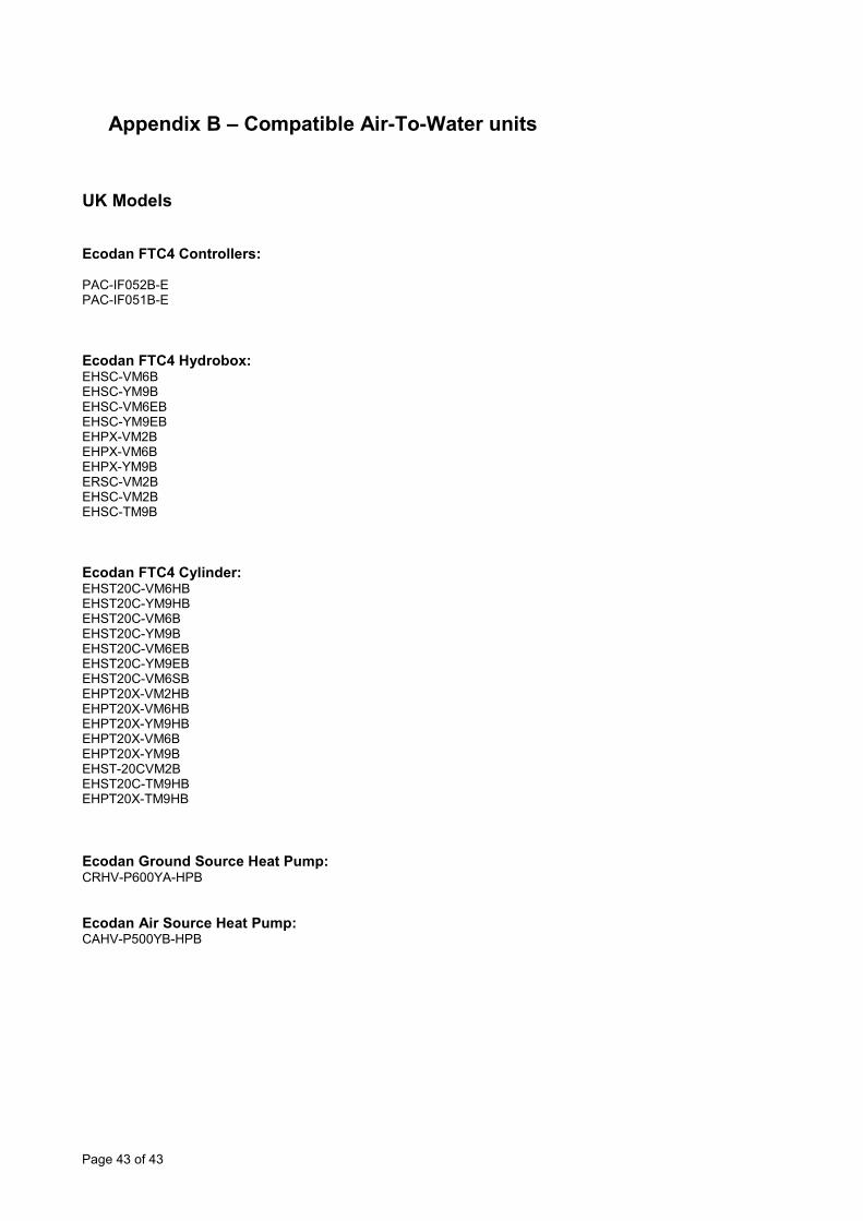
Appendix B – Compatible Air-To-Water units
UK Models Ecodan FTC4 Controllers: PAC-IF052B-E PAC-IF051B-E Ecodan FTC4 Hydrobox: EHSC-VM6B EHSC-YM9B EHSC-VM6EB EHSC-YM9EB EHPX-VM2B EHPX-VM6B EHPX-YM9B ERSC-VM2B EHSC-VM2B EHSC-TM9B Ecodan FTC4 Cylinder: EHST20C-VM6HB EHST20C-YM9HB EHST20C-VM6B EHST20C-YM9B EHST20C-VM6EB EHST20C-YM9EB EHST20C-VM6SB EHPT20X-VM2HB EHPT20X-VM6HB EHPT20X-YM9HB EHPT20X-VM6B EHPT20X-YM9B EHST-20CVM2B EHST20C-TM9HB EHPT20X-TM9HB Ecodan Ground Source Heat Pump: CRHV-P600YA-HPB Ecodan Air Source Heat Pump: CAHV-P500YB-HPB


Please be sure to put the contact address/telephone number on this manual before handing it to the customer.
MITSUBISHI ELECTRIC UK MITSUBISHI ELECTRIC UK, TRAVELLERS LANE, HATFIELD, HERTFORDSHIRE, AL10 8XB