Process Waste Treatment System Upgrades: Clarifier Startup ...
18
/ 1 ORNMM-13654 Process Waste Treatment System Upgrades: Clarifier Startup at the Nonradiological Wastewater Treatment Plant A. J. Lucero D. R. McTaggart B. C. VanEssen T. E. Kent G. D. West P.A. Taylor
Transcript of Process Waste Treatment System Upgrades: Clarifier Startup ...

/ 1
ORNMM-13654
Process Waste Treatment System Upgrades: Clarifier Startup at the
Nonradiological Wastewater Treatment Plant
A. J. Lucero D. R. McTaggart B. C. VanEssen
T. E. Kent G. D. West P.A. Taylor

This report has been reproduced directly from the best available copy.
Available to DOE and DOE contractors from the Office of Scientific and Technical Information, P.O. Box 62, Oak Flidge, TN 37831; prices available from (423) 576-8401, FTS 626-8401.
I This report was prepared as an account of work sponsored by an agency of the United States Government. Neither the United States Government nor any agency thereof, nor any of their employees, makes any warranty, express or implied, or assumes any legal liability or responsibility for the accuracy, completeness, or usefulness of any information. apparatus, product, or process disclosed, or represents that its use would not infringe privately owned rights. Reference herein to any specific commercial produc<!, process, or service by trade name, trademark, manufacturer, or otherwise, does not necessarily constitute or imply its endorsement, recommendation, or favoring by the United States Government or any agency thereof. The views arid opinions of authors expressed herein do not necessarily state or reflect those of the United States Government or any agency thereof.

DISCLAIMER
Portions of this document may be illegible in electronic image products. Images are produced from the best available original document.

ORNLRM-13654
Chemical Technology Division
PROCESS WASTE TREATMENT SYSTEM UPGRADES: CLARIFIER STARTUP AT THE NONRADIOLOGICAL
WASTEWATER TREATMENT PLANT
A. J. Lucero D. R. McTaggart D. C. VanEssen
T. E. Kent G. D. West P. A. Taylor
Date Published: July 1998
Prepared for Waste Management Operations Division
Oak Ridge National Laboratory
Prepared by the OAK RIDGE NATIONAL LABORATORY
Oak Ridge, Tennessee 37831-6285 managed by
LOCKHEED MARTIN ENERGY RESEARCH COW. for the
U.S. DEPARTMENT OF ENERGY under contract DE-AC05-960R22464


CONTENTS
ABSTRACT . . . . . . . . . . . . . . . . . . . . . . . . . . . . . . . . . . . . . . . . . . . . . . . . . . . . . . . . . . . . . . . . . . 1
1 . INTRODUCTION . . . . . . . . . . . . . . . . . . . . . . . . . . . . . . . . . . . . . . . . . . . . . . . . . . . . . . . . . 1
2 . BACKGROUND . . . . . . . . . . . . . . . . . . . . . . . . . . . . . . . . . . . . . . . . . . . . . . . . . . . . . . . . . . 2
3 . PROCESS CHEMISTRY . . . . . . . . . .................................. . . . . . . . . . 3
4 . SYSTEMDESCRIPTION ................................................... 3
5 . EXPERIMENTALPLAN ................................................... 3
6 . ANALYTICAL TECHNIQUES ............................................... 4
. ................................................................. 7 RESULTS 5 7.1 Flocculant-Tank Mixing Tests ............................................ 5
7.3 System Performance .................................................... 7 7.2 Reagent Delivery ....................................................... 5
8 . CONCLUSIONS .......................................................... 10
9 . REFERENCES ........................................................... 10
... 111


PROCESS WASTE TREATMENT SYSTEM UPGRADES: CLARIFIER STARTUP AT THE NONRADIOLOGICAL
WASTEWATER TREATMENT PLANT
A. J. Lucero, D. R. McTaggart, D. C. VanEssen, T. E. Kent, G. D. West and P. A. Taylor
ABSTRACT
The Waste Management Operations Division at Oak Ridge National Laboratory recently modified the design of a reactor/clarifier at the Nonradiological Wastewater Treatment Plant, which is now referred to as the Process Waste Treatment Complex-Building 3608, to replace the sludge-blanket softener/clarifier at the Process Waste Treatment Plant, now referred to as the Process Waste Treatment Complex-Building 3 544 (PWTC-3 544). This work was conducted because periodic hydraulic overloads caused poor water-softening performance in the PWTC- 3544 softener, which was detrimental to the performance and operating costs of downstream ion- exchange operations. Over a 2-month time frame, the modified reactorklarifier was tested with nonradiological wastewater and then with radioactive wastewater to optimize softening performance. Based on performance to date, the new system has operated more effectively than the former one, with reduced employee radiological exposure, less downtime, lower costs, and improved effluent quality.
1. INTRODUCTION
The Waste Management Operations Division (WMOD) operates facilities at Oak Ridge
National Laboratory for treatment of wastewater containing radiological and hazardous
pollutants. The effluent wastewater must meet the discharge criteria defined in a National
Pollutant Discharge Elimination System permit and in U.S. Department of Energy Order 5400.5,
“Radiological Protection of the Public and Environment.” The Process Waste Treatment
Complex-Building 3544 (PWTC-3544) removes radioactive strontium-90 (90Sr) and
cesium-137 (137Cs) from approximately 70 million gallons per year of wastewater, using
chemical sofiening and ion exchange. The Process Waste Treatment Complex-Building 3608
(PWTC-3608) removes heavy-metal and organic pollutants from approximately 170 million
gallons per year by using chemical precipitation, air stripping, and activated carbon. The effluent
wastewater from the PWTC-3544 is further treated at the PWTC-3608 for removal of trace
organic components. The operating capacity and efficiency of the PWTC-3544 were limited by
1

the softener/clarifier system, which was undersized and sometimes troublesome to operate. The
PWTC-3608, however, was designed for rnwh higher wastewater flow rates and had redundant
capacity for chemical precipitation and clarification of wastewater. With improved
administrative control of pollutant discharges, segregation of wastewaters, and reduced quantities
of heavy-metal discharges from generator sources, the two reactor/clarifier units at the
PWTC-3608 were underutilized. In September 1993, a design study was completed that
examined the feasibility of using one of the two PWTC-3608 reactor/clarifiers as a softener for
the radiological process wastewater.' This approach reduced costs by avoiding construction of a
replacement softener/clarifier at the PWTC-21544 and furthered the goal of consolidating all
process wastewater treatment operations at one facility, which would significantly reduce
operating costs. The treatment capabilities of the PWTC-3608 reactor/clarifier were improved by
addition of a flocculation tank and a sludge-1,ecycle system for enhancing the softening reaction.
This report describes the startup, optimization, and performance evaluation for this system.
2. BACKGROUND
To improve the efficiency of 137Cs and 9')Sr ion-exchange operations at the Process Waste
Treatment Plant, the wastewater is softened in a sludge-blanket clarifier, L-1 , to reduce the
hardness from 150-200 mg/L CaCO, to 6-1 13 mg/L. WMOD personnel observed that periodic
hydraulic overloads caused poor performance in the L-1 clarifier. Since the reactodclarifiers
(F- 1006 and F- 1007) at the PWTC-3608 were being operated at only a fraction of their design
capacity, M O D decided to use one of these, F-1006, to soften the feed to the PWTC-3544,
providing enough softening capacity to handle periods of high demand. The reactodclarifier
effluent is sent to the PWTC-3 544 for removal of radioactive contaminants using ion-exchange
columns. The effluent from the PWTC-3544 is then sent back to the PWTC-3608 for removal of
any organic contaminants.
2

3. PROCESS CHEMISTRY
The softening process is a series of reactions initiated by pH adjustment to 1 1.5. The
primary effect of the hydroxide is to convert bicarbonate ions to carbonate, thus precipitating
calcium as CaCO,. The second effect is to precipitate magnesium as Mg(OH),. The softening
process also removes about 70% of the 90Sr from the wastewater and most other heavy metals
that may be present.
4. SYSTEM DESCRIPTION
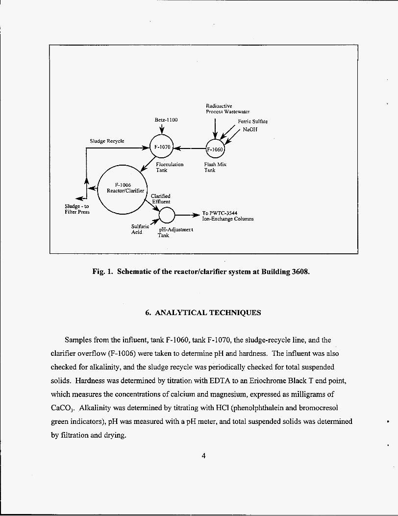
A simplified schematic of the F-1006 clarifier system is shown in Fig. 1. The process feed
enters the system into a 975-gal flash mix tank (F-1060), where the pH is adjusted to 11.5 with
sodium hydroxide and ferric sulfate is added as a flocculant. The waste then flows to a
10,000-gal flocculation tank (F-lO70), where Betz 1 100 polyelectrolyte (Betz Laboratories,
Trevose, Pennsylvania) is added. Solids are then settled in a 60,000-gal reactorhlarifier (F-
1006), with approximately 10% of the flow being recycled from the sludge layer back to F- 1070.
To reduce possible post-precipitation problems, the effluent pH is adjusted to between 6 and 10
before being pumped to PWTC-3544 for ion- exchange treatment. The system is monitored and
controlled inside Building 3608 from a distributed control system.
5. EXPERIMENTAL, PLAN
The experimental plan focused on determining the chemical and mechanical parameters that
would optimize the removal of water-hardness components from the wastewater prior to ion-
exchange treatment at Building 3544. The primary variables to be optimized included flow rates
(and therefore concentrations) of ferric sulfate and Betz 1100, recycle flow (0 to 35 gal/min),
mixer speed in tank F-1070 (0 to 50 rpm), and sludge-withdrawal rate. The system was initially
started with nonradiological wastewater for equipment checkout and leak tests,
3
Radioactive Process Wastewater
Betz-1100 I Ferric Sulfate
Flocculation Tank
F- 1006 ReactorKlarifier
Clarified
Sludge - t o Filter Press
Flash Mix Tank
TO PWTC-3544 Ion-Exchange Columns
Sulfuric Acid Tank pH-Adjustmen t
Fig. 1. Schematic of the reactorklarifier system at Building 3608.
6. ANALYTICAL TECHNIQUES
Samples fiom the influent, tank F-1060, tank F-1070, the sludge-recycle line, and the
clarifier overflow (F-1006) were taken to determine pH and hardness. The influent was also
checked for alkalinity, and the sludge recycle was periodically checked for total suspended
solids. Hardness was determined by titration with EDTA to an Eriochrome Black T end point,
which measures the concentrations of calcium and magnesium, expressed as milligrams of
CaCO,. Alkalinity was determined by titrating with HC1 (phenolphthalein and bromocresol
green indicators), pH was measured with a pH meter, and total suspended solids was determined
by filtration and drying.
4

7. RESULTS
7.1 Flosculant-Tank Mixing Tests
During initial leak testing and equipment checkout, a series of experiments was conducted to
determine static mixing times for tank F-1070 at various mixer speeds. A spike of sodium
chloride was added to the water in the tank, and the conductivity of the solution was monitored
over time. The purpose of these experiments was to determine mixer speeds that would
completely mix the tank contents in less than one-fifth the hydraulic residence time during
operation. This would ensure complete mixing of all reagents before they entered the clarifier.
The results of these experiments indicated that at least 20 rpm was necessary for a flow rate of 150 gal/min and that 30 rpm was necessary for flow rates of 300 gal/min. (Hydraulic residence
time at 300 gal/min is 33 min.) Figure 2 shows static mixing times determined in these tests as a
function of stirrer speed. Based on this information, the stirrer speed was set and left at 30 rpm
for the rest of the tests to allow time and effort to be focused on other issues.
7.2 Reagent Delivery
As initial testing with nonradioactive water began, it immediately became apparent that the
reagent-delivery systems were not functioning as designed. The ferric sulfate pumps (constant-
volume pumps) failed periodically and did not maintain desired flow rates. The pumps, which
were installed above the supply tank and were pulling 6 f t of suction lift before pumping the
solution through about 180 ft of tubing to the process, were overloaded. Relocating the pumps to
eliminate the suction lift solved this problem.
Additional difficulties were encountered with the Betz 1 100 polymer-delivery system.
Overpressure protection valves for the polymer pumps leaked to such an extent that accurate
5

16 , A
S .- E Y
m S K .- z
14
12
10
8 6
4 2
0 20 30 40 50
Stir'rer Speed (rpm)
Fig. 2. Mixing time vs stirrer speed for F-1070 tank.
determination of polymer flow to (and therefore polymer concentration in) the system was
impossible. On inspection, it was found that the discharge line from the valves was plugged and
that polymer was leaking onto the floor. The: valves had been installed in such a manner that any
discharge from them had to travel upward back to the polymer tank. This left polymer in the line
after a discharge, which solidified and plugged the line. The valves were relocated so that their
discharge traveled downward to the polymer tank, eliminating plugging. Repairs were also made
to the valves to ensure that they did not discharge as easily.
A second issue related to proper makeup of the polymer. Prior to this upgrade, the clarifier
had been run in a batch mode. Batches of polymer were made up in the polymer feed tank prior
to the start of a run, and the run ended when the polymer supply was depleted. The new system
runs continuously, so polymer batches are made up more often, with less time for mixing.
(Polymer powder takes at least 1 h to dissohe and must be carefully added to the water to avoid
forming clumps, which take much longer to dissolve.) To ensure ample time for the polymer to
6

mix and dissolve, a polymer premix tank was added. Concentrated polymer is made up in the
premix tank and sent to the polymer feed tank when needed. A large sifter was obtained, which
can be used to distribute the polymer powder evenly in the premix tank and reduce clumping.
7.3 System Performance
During initial checkout with nonradioactive water, the effluent hardness varied widely.
Much of the poor performance was due to pump failures and other equipment malfunctions.
During early testing, the ferric sulfate pumps failed, and the sludge-recycle pumps regularly shut
down due to high discharge pressure. After each problem was corrected, several days was
required for the system to recover. Figure 3 shows the effluent hardness from the system during
tests with nonradioactive wastewater. After the operational difficulties were corrected, the
hardness concentration in the clarifier effluent was still higher than desired. Bench-scale tests on
the nonradioactive water showed that a slight deficiency in carbonate was preventing optimum
reductions. Several 50-lb bags of soda ash were purchased and added to the influent ofthe
system over several days. This reduced the effluent hardness from about 70 mg/L to 30 mg/L.
The tests with nonradioactive wastewater were discontinued to make final preparations for
treating radioactive wastewaters.
After the feed to the system was shifted to radioactive wastewater, the effluent hardness fell
to below 10 mg/L over a period of 2 weeks. When the flow rate of the ferric sulfate was
inadvertently reduced, the hardness quickly rose to about 30 mg/L. The flow rate of the ferric
sulfate was readjusted, and the effluent hardness fell to below 10 mg/L in about a week. The
hardness tends to rise when a process upset occurs and then falls when it is corrected. Figure 4 shows the effluent hardness from the start of processing radioactive wastewaters on 5/1/97
through 7/3 1/97.
7

A
E a Q v
* 7
+ - * + 40
03/01 197 03/11 /97 03/21 /97 03/31 /97 04/1 0/97 04/20/97 Date
Fig. 3. Total hardness concentration for effluent from F-1006 reactodclarifier during treatment of nonradioactive process wastewater.
Several operational parameters were not optimized for the reasons listed below;
however, the system performance remains excellent. The sludge-recycle rate remains at
30 gal/min (close to its maximum of 35 gal/rnin) because the recycle line tends to plug with
solids if the flow rate is reduced. Since the system functioned well with the stirrer speed set at
30 rpm, other speeds were not tested, and it was left unchanged. The ferric sulfate flow rate is
set to produce a concentration of 5 mgk. Several bench-scale tests have confirmed that higher
concentrations do not significantly improve performance, but full-scale tests at higher
concentrations were not performed. The polymer concentration remains at 2.5 mgk . Both the
sludge-withdrawal rate and the set point of the final effluent pH are adjusted by WMOD
personnel as necessary.
8

n
E P P cn cn Q, S
v
E - m 0 I- U
_ -
30 : * v * v b e
*# ** * *
* *
** * * * *
1
I
Date
Fig. 4. Total hardness concentration for effluent from F-1006 reactorhlarifier during treatment of radiological process wastewater.
Since the test period ended, the system has been operating for almost a year without any
major problems. The sludge-recycle line requires cleaning periodically, and the line between the
flocculation tank and the reactorklarifier has been cleaned once. The acid-addition pumps were
recently replaced with slightly larger pumps. The hardness concentration in the clarifier effluent
has typically ranged from 2 to 6 m a . Because of the low concentration of calcium and
magnesium in the softened wastewater, the ion-exchange columns at the PWTC-3544 are more
efficient. The average 90Sr in the effluent from the ion-exchange columns has been reduced
from 10 to 1 BqL. The amount of water that can be treated by the ion-exchange columns before
regeneration is required has increased significantly, which reduces the amount of liquid low-level
waste produced at the PWTC-3544. The average throughput was 1,183,400 gal before the
change to the new clarifier system and 1,504,300 gal after, an increase of 27%.
9

8. CONCLUSIONS
The reactorklarifier at Building 3608 has been consistently reducing the hardness of the
influent from 160-200 mg/L to below 10 mg/L at a variety of flow rates. Several problems of a
mechanical/processing nature that were affecting the operation of the system were resolved
during the test period. The system has been operating routinely for over a year, with only minor
problems. The hardness concentration in the effluent from the new clarifier is lower than it was
with the old softener, which has improved the operation of the ion-exchange columns at the
PWTC-3544 and reduced the amount of secondary waste produced.
9. REFERENCES
1. NR WTP Clarifier Modifications Feasibility Study Summary Report, Engineering-Science,
Inc., Atlanta, September 1993.
10

INTERNAL DISTRIBUTION
1. 2. 3. 4. 5. 6 . 7.
5-10. 11. 12. 13.
14-15.
T. E. Kent P. S. Kirkham A. J. Lucero D. R. McTaggart S. M. Robinson S . T. Rude11 C. B. Scott P. A. Taylor G. D. West Central Research Library Laboratory Records - RC Laboratory Records - for submission to OSTI
ORNL/TM-13654