Process Safety: Achieving higher quailty with optical measuring
5
Price 9,50 € Issue 2/11 ISSN 1860-4935 www.vdwf.de The Magazine of the German Association of Tool and Mold Makers Process Safety: Achieving higher quailty with optical measuring systems
Transcript of Process Safety: Achieving higher quailty with optical measuring

Price 9,50 € Issue 2/11 ISSN 1860-4935 www.vdwf.de
The Magazine of the German Association of Tool and Mold Makers
VDW
F im
Dia
log
Aus
gabe
2/1
1 P
ress
ed C
hair
L
aser
tech
nik
bei d
er M
ikro
grav
ur
M
ediz
inte
chni
k: Im
plan
tate
M
alay
sia
Akk
usch
raub
erre
nnen
Process Safety:Achieving higher quailty with optical measuring systems
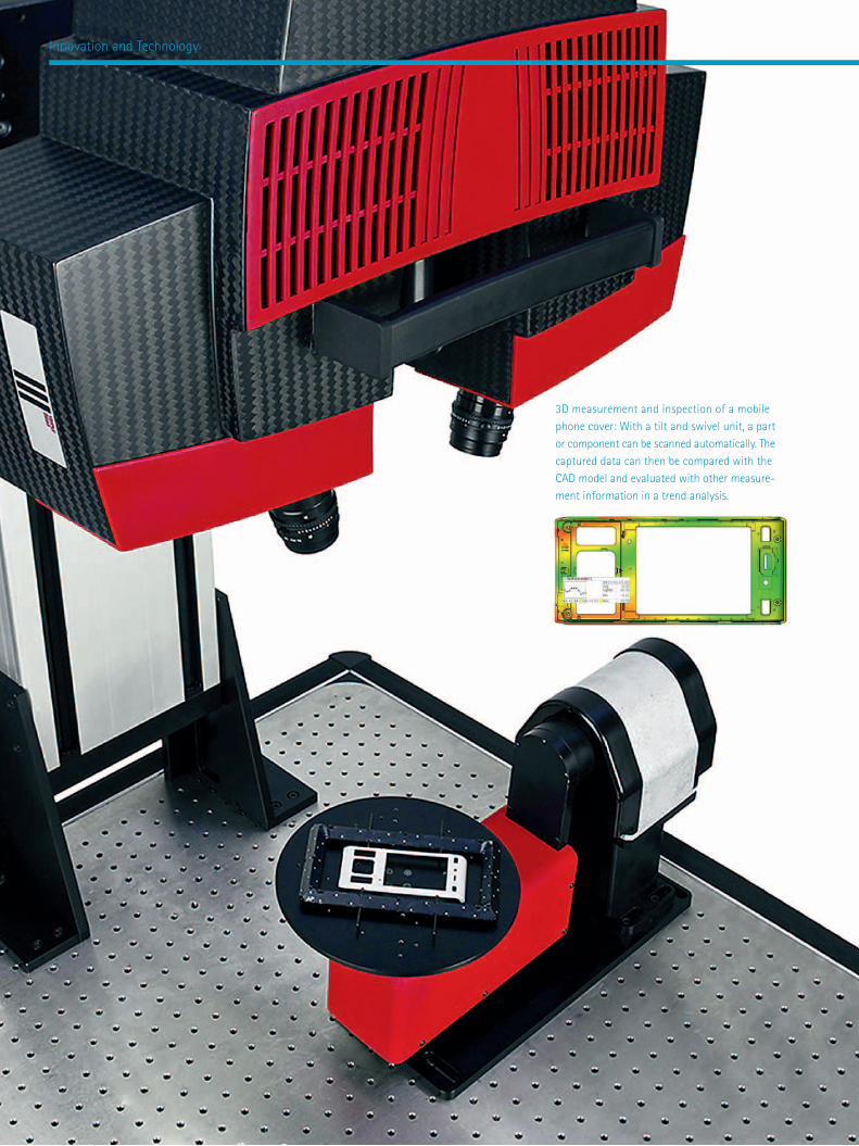
3D measurement and inspection of a mobile phone cover: With a tilt and swivel unit, a part or component can be scanned automatically. The captured data can then be compared with the CAD model and evaluated with other measure-ment information in a trend analysis.
Innovation and Technology

Mobile Scanning without Limits –New Perspectives with Optical 3D Metrology by Fabian Diehr
VDWF im Dialog 2/2011 19
In recent years, the complexity of parts in the plastics processing industry has increased, generating high demand for the development and use of new metrology procedures to optimize the complete process chain in industrial environ-ments. Standards in quality assurance are now set by three-dimensional optical measurement technologies such as those developed, manufactured and distributed by GOM (Gesell-schaft für Optische Messtechnik) of Braunschweig, Germany, one of the world’s leading providers of 3D metrology solu-tions. GOM rolled out the first 3D metrology systems 20 years ago and has continued to improve and develop this precision technology ever since. The company is a market leader with some 200 employees who are dedicated to serving customers worldwide in the automotive, aviation, aerospace and consumer goods industries, as well as uni-versities, research institutes and material manufacturers.
The Atos 3D digitizer is a precise, fast and robust metrology solution produced in Germany that is deployed successfully and reliably around the world in injection molding, thermoplastic and injection blow molding process chains. This technology combines extreme measurement data accuracy with high flexibility in a design that makes the Atos 3D digitizer well suited for mobile application in all kinds of manufacturing environments. «Optical scanning,» says Stephanie Adolf, responsible for technical market-ing at GOM, «is a revolution. The metrology is clearly oriented toward the customer or the object to be inspected and not the other way around, as it used to be in the past.»
High-resolution point cloud
The technical principle is quite easy to explain: Instead of sampling individual points, the entire surface geometry of a component is captured in a high-resolution point cloud. Stephanie Adolf draws attention to the special characteristics of this process: «In contrast to laser scanners, the fringe projection method depicts stripe patterns across the entire surface of a part. Depend-ing on exposure requirements, the scanning time is usually just a few seconds. In our method the object is scanned using two cameras. Thus three-dimensional object coordinates of the object’s surface can be precisely measured for every camera pixel. The GOM stereo camera system ensures the highest possible process security – for each measurement the system checks for valid calibration. Also possible position or lighting changes are detected so that only precise and accurate scanning data is captured.»
Fast, full-� eld veri� cation of car bumper measure-ments against CAD: For mobile use, the 3D scanner is mounted on a mobile stand and positioned manually. The 3D scanning process on the part and comparison with the CAD data set requires only four measurements and takes about three minutes to complete. When used in combination with the parametric approach that forms the basis for GOM Inspect Professional evaluation software, this technology simpli� es 2D-drawings and considerably reduces the processing time required for test and inspection reports. Instead of using a macro engine, each individual element knows its path of creation within the software structure. All actions and evaluation steps are therefore traceable and interlinked. A one-button solution updates all dependent elements auto-matically after changes have been made.

20 VDWF im Dialog 2/2011
leagues. In the future the 3D scanner will be among the essential unique selling points in leading metrology companies. To stay competitive, tool and mold makers must at least offer 3D scanning as a service in their first article inspection reports.»
Even mold inserts can be scanned directly and quickly so that measurements can be compared with digital data sets. «Serious mistakes – such as reversed digits in NC programming – can easily be discovered before expensive finishing processes begin,» Willi Schmid emphasizes. The more complex a geometry is, the more complex the tactile measuring will be. With optical systems, however, you get equally or even more precise data, which can then be processed completely and, above all, quickly. Another advantage over tactile measurement is the ability to immediately continue working with optically generated point clouds. Using the scanned 3D data, for example, reverse engi-neering can be carried out to create a CAD model of a part or tool.
High-precision quality control
Warp, shrinkage and deformations, or even wall thickness analyses and the control of material accumulation are events in plastic injection molding that cannot be calculated with current CAD software. Jochen Maass, CAQ engineer at Braun GmbH in Kron-berg, Germany, is always amazed by the lack of such knowledge in his own branch of industry: «With modern evaluation software you can measure components extremely quickly and precisely. Especially in the area of plastics technology I can see the con-siderable advantages of using optical 3D metrology, because we often work here with free-form geometries. And they cannot be analyzed with microscopes or tactile measurement methods. But if you use a 3D scanner, there is absolutely no problem inspecting components in terms of material, size or type of surface.» And we should also remember that optical metrology is well-suited for measuring components as prototypes, in the pre-series phase and during first article inspection to quickly find any problems. Even the smallest details can be scanned, as well as complex shapes and deep recesses, thanks to the Triple Scan principle of the Atos 3D digitizer, which is a reliable
Within a very short time the user has a complete 3D model of the component as well as a test report. The scanning process is essentially automatic because the individual measurements are coordinated using reference marks or geometric-based computations – all without user intervention. There is no need to interrupt the scanning process for any manual opera-tions. «But the best feature of optical scanning is the fact that the system captures the complete part geometry meas-uring the entire surface of the component leaving virtually no blind spots – this is not possible with tactile measurement. What’s more, the system is completely mobile,» notes Steph-anie Adolf, underlining the advantages offered by the Atos 3D digitizer: «Either the object or the scanner system is posi-tioned as required, the latter being especially helpful when inspecting very large or heavy components.»
The investment needed for such a metrology solution primarily depends on the customer’s individual requirements and config-uration. In terms of price structure, the situation is similar to buying a new automobile in the upper middle-class range – anything is available, from standard equipment to models that have all the extras.
Faster part inspection
In daily practice the initial investment is more than justified. The Atos 3D digitizer generates precise coordinates for full-field verification against CAD data as well as section-based and material thickness analyses, including complete measurement and inspection reports to speed up first article inspection and targeted tool correction. Irregularities are detected immediately, without having to work through long and complex tables. Visu-alization speeds up component assessment so that specific corrective measures can be initiated promptly. This process has a number of clear advantages over tactile measuring devices – and these advantages pay off in terms of investment. Willi Schmid, CEO of VDWF, recognizes the future value that these advantages will deliver: «Ten years ago the main tool was still a caliper gauge, but today every tool and mold maker must have his own high-tech measuring lab if he wants to play in the big
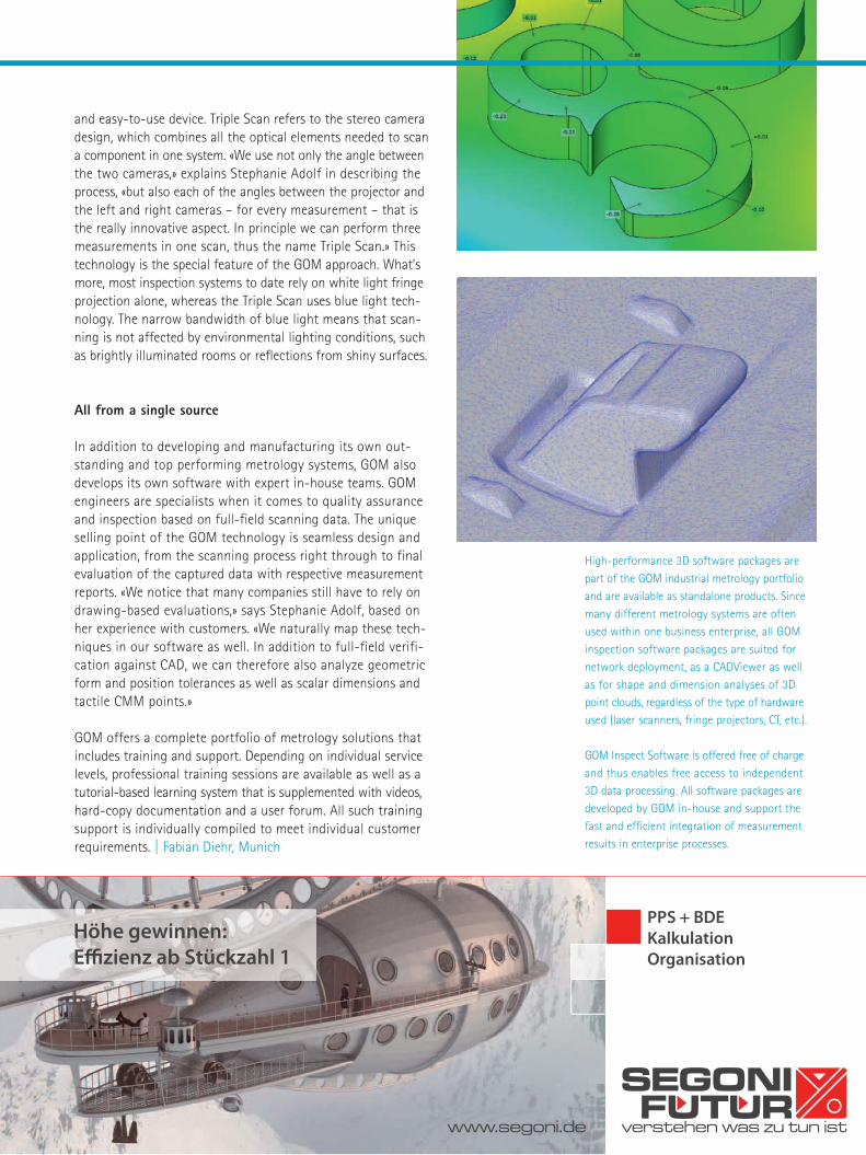
and easy-to-use device. Triple Scan refers to the stereo camera design, which combines all the optical elements needed to scan a component in one system. «We use not only the angle between the two cameras,» explains Stephanie Adolf in describing the process, «but also each of the angles between the projector and the left and right cameras – for every measurement – that is the really innovative aspect. In principle we can perform three measurements in one scan, thus the name Triple Scan.» This technology is the special feature of the GOM approach. What’s more, most inspection systems to date rely on white light fringe projection alone, whereas the Triple Scan uses blue light tech-nology. The narrow bandwidth of blue light means that scan-ning is not affected by environmental lighting conditions, such as brightly illuminated rooms or reflections from shiny surfaces.
All from a single source
In addition to developing and manufacturing its own out-standing and top performing metrology systems, GOM also develops its own software with expert in-house teams. GOM engineers are specialists when it comes to quality assurance and inspection based on full-field scanning data. The unique selling point of the GOM technology is seamless design and application, from the scanning process right through to final evaluation of the captured data with respective measurement reports. «We notice that many companies still have to rely on drawing-based evaluations,» says Stephanie Adolf, based on her experience with customers. «We naturally map these tech-niques in our software as well. In addition to full-field verifi-cation against CAD, we can therefore also analyze geometric form and position tolerances as well as scalar dimensions and tactile CMM points.»
GOM offers a complete portfolio of metrology solutions that includes training and support. Depending on individual service levels, professional training sessions are available as well as a tutorial-based learning system that is supplemented with videos, hard-copy documentation and a user forum. All such training support is individually compiled to meet individual customer requirements. | Fabian Diehr, Munich
verstehen was zu tun ist
SEGONIFUTUR
Höhe gewinnen: Effi zienz ab Stückzahl 1
PPS + BDEKalkulationOrganisation
www.segoni.de
High-performance 3D software packages are part of the GOM industrial metrology portfolio and are available as standalone products. Since many different metrology systems are often used within one business enterprise, all GOM inspection software packages are suited for network deployment, as a CADViewer as well as for shape and dimension analyses of 3D point clouds, regardless of the type of hardware used (laser scanners, fringe projectors, CT, etc.).
GOM Inspect Software is offered free of charge and thus enables free access to independent 3D data processing. All software packages are developed by GOM in-house and support the fast and efficient integration of measurement results in enterprise processes.


![Untappable communication channels over optical bers · PDF fileUntappable communication channels over optical bers ... [BB84], where achieving more than 1 Mb/s seems to be hard, especially](https://static.fdocuments.in/doc/165x107/5aa91b8c7f8b9a90188c60da/untappable-communication-channels-over-optical-bers-communication-channels-over.jpg)