Process Plant design fundementals
110
Fundamentals of Process Plant Design
-
Upload
greg-pajak-p-tech-eng-isa84-sis-expert -
Category
Engineering
-
view
3.384 -
download
11
Transcript of Process Plant design fundementals

Fundamentals of Process Plant Design

Goals and Objectives
Understand the basic fundamentals of an EPC role in Process Plant Engineering.
Help / Guide you in your job to try and apply some thought, where can you add value to the industry we serve.
Presentation where we can learn about Plant Design. Does not cover all aspects of Plant Design. Does not cover all industries Not about making you a Piping Designer

Plant Design Workflow
Process Simulations
Concept Selected
Process Flow Diagrams
Preliminary P&IDs
Preliminary GAs
Preliminary Layouts
CAPEX+/- 30%
Instrument & Electrical Schematics
Process and Utility P&IDs
Initiate 3D Plant Design
Data Sheets
HAZOP / Safety Reviews
CAPEX+/- 15%
Concept Selection (Pre-FEED) Front-End Engineering and Design (FEED)
Feed Defined
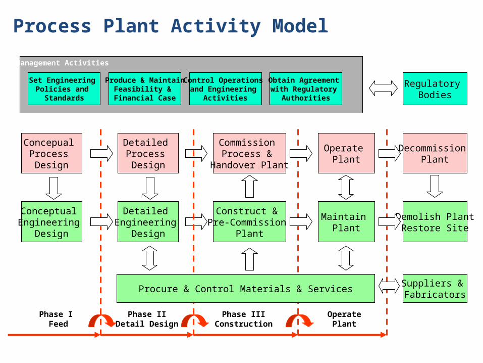
Process Plant Activity Model
Set Engineering Policies and
Standards
Produce & MaintainFeasibility &
Financial Case
Control Operations and Engineering
Activities
Obtain Agreement with Regulatory
Authorities
Management Activities
Regulatory Bodies
Conceptual Engineering
Design
Concepual Process Design
Phase I Feed
Commission Process &
Handover Plant
Construct & Pre-Commission
Plant
Phase IIIConstruction
Operate Plant
Maintain Plant
OperatePlant
Decommission Plant
Demolish PlantRestore Site
Suppliers & Fabricators
Detailed Process Design
Detailed Engineering
Design
Procure & Control Materials & Services
Phase IIDetail Design

Process department and its role Process Engineering focuses on Design, Operation, Control and
Optimisation of Chemical, Physical and Biological processes Translate a customer needs into a production facility – Safely &
Productive Block Diagram FEED (Front End Engineering and Design) PFD (Process Flow Diagram)

PFD (Process Flow Diagram)
This figure depicts a small and simplified PFD:System Flow Diagrams should not include: pipe class pipe line numbers minor bypass lines isolation and shutoff valves maintenance vents and drains relief and safety valve code class information seismic class information

PFD (Process Flow Diagram)
A PFD should include: Process Piping Major equipment symbols, names and identification numbers Control, valves and valves that affect operation of the system Interconnection with other systems Major bypass and recirculation lines System ratings and operational values as minimum, normal and
maximum flow, temperature and pressure Composition of fluids
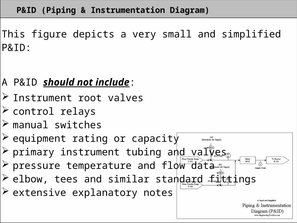
P&ID (Piping & Instrumentation Diagram)
This figure depicts a very small and simplified P&ID:
A P&ID should not include: Instrument root valves control relays manual switches equipment rating or capacity primary instrument tubing and valves pressure temperature and flow data elbow, tees and similar standard fittings extensive explanatory notes
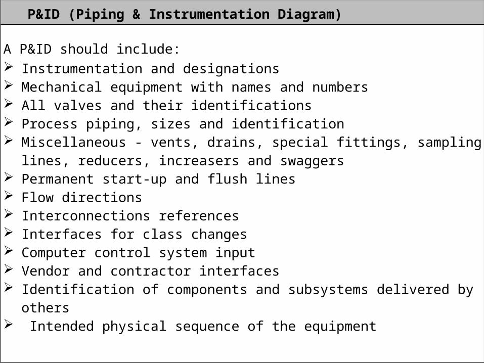
P&ID (Piping & Instrumentation Diagram) A P&ID should include: Instrumentation and designations Mechanical equipment with names and numbers All valves and their identifications Process piping, sizes and identification Miscellaneous - vents, drains, special fittings, sampling lines, reducers, increasers
and swaggers Permanent start-up and flush lines Flow directions Interconnections references Interfaces for class changes Computer control system input Vendor and contractor interfaces Identification of components and subsystems delivered by others Intended physical sequence of the equipment

PFD (Process Flow Diagram)

P&ID (Piping and Instrumentation Diagram)

P&ID (Piping and Instrumentation Diagram)

P&ID / Project deliverables Symbology

P&ID / Project deliverables Symbology

P&ID / Project deliverables Symbology
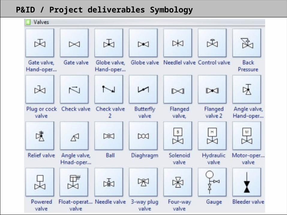
P&ID / Project deliverables Symbology

P&ID / Project deliverables Symbology
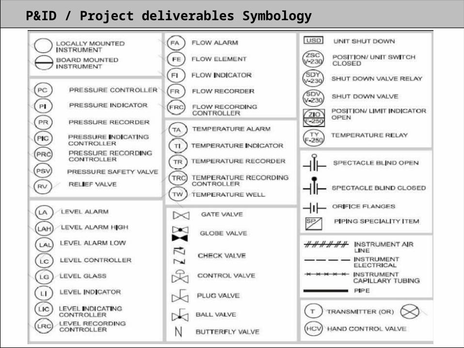
P&ID / Project deliverables Symbology

P&ID / Project deliverables Symbology
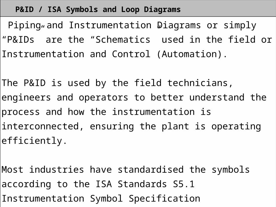
P&ID / ISA Symbols and Loop Diagrams
Piping and Instrumentation Diagrams or simply “P&IDs” are the “Schematics” used in the field or Instrumentation and Control (Automation).
The P&ID is used by the field technicians, engineers and operators to better understand the process and how the instrumentation is interconnected, ensuring the plant is operating efficiently.
Most industries have standardised the symbols according to the ISA Standards S5.1 Instrumentation Symbol Specification

Temperature Process / Loop Diagram

Tag Numbers in a Loop

Tag Numbers

Tag Descriptors
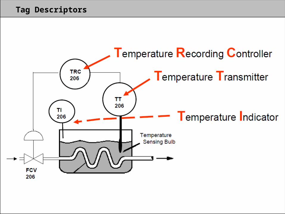
Tag Descriptors

Instrumentation Location
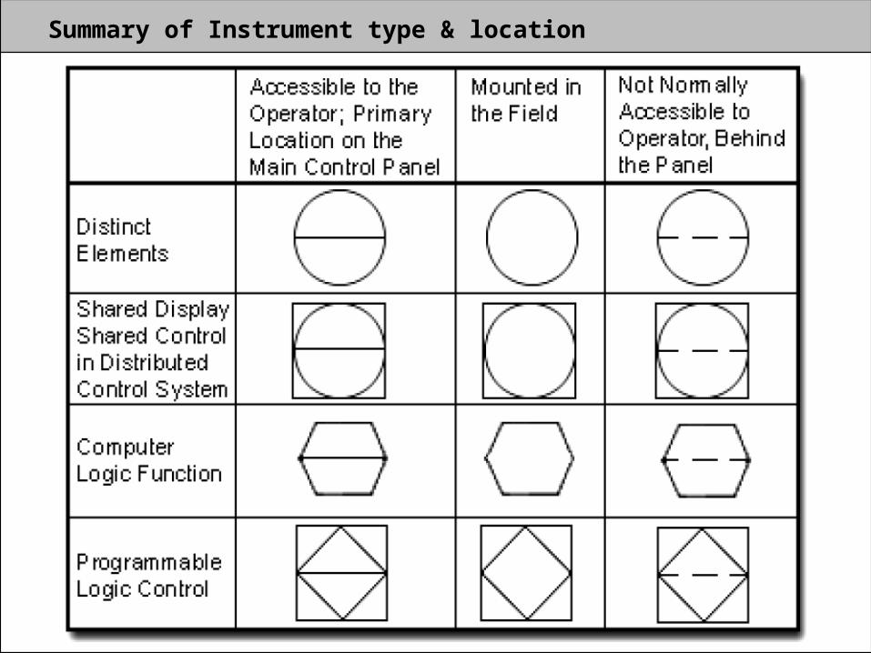
Summary of Instrument type & location

Piping and Connection Symbols

Instrument Valve Symbols

P&ID Example of a Instrument Loop

P&ID Exercise
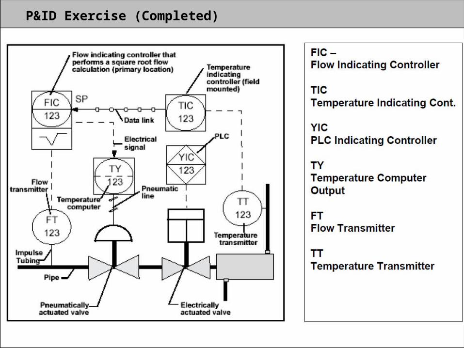
P&ID Exercise (Completed)

Pipeline Naming
150 – Line Size Nominal Dia PV – Service Code 20 – System 2002 – Sequence Number AD20XS – Pipe Class 03 – Insulation Class 050 – Insulation Thickness N – Heat Tracing
150-PV-20-2002-AD20XS-03-050-N

Pipe Spec Breaks
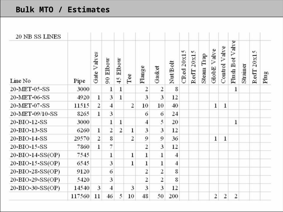
Bulk MTO / Estimates
Piping / Mechanical Department and its Role
Piping EngineeringA Major phase in the life of process plants

Basics of Plant Layout Design
Instruments
Electrical
ClientRotating Equipment
Scheduling
Civil/Structural
Process
Specifications
Systems
Furnace
ExchangersMaterials
InspectionConstruction
Project Engineering
Computer Applications
Vessels
Mechanical
Plant Layout

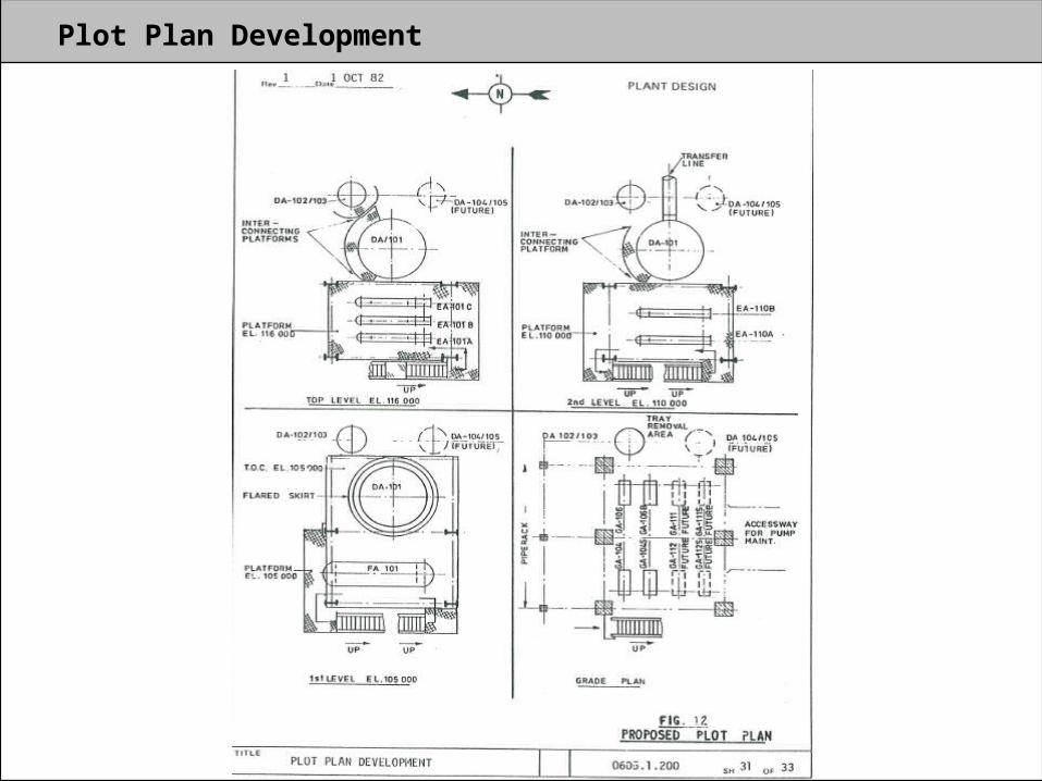
Plot Plan Development

Plot Plan Development Indicate all Major equipment items Building outlines Battery Limits Area Limits of responsibility Piping Entry and Exit Points Access ways Roadways Main Structure – Stairways Piperacks Dimensions kept to a minimum Show all Easting/Northings – Elevations True North Plot Plans supplied by Clients (FEED Specifications)

Plot Plan Development – General Information Required Site Plans Project Design Information – Client Standards Equipment List PFD and P&ID Utility conditions – Cooling Water, Steam, etc Preferred locations of exit and entry piping points Electrical Cables entry points Client / EPC Standards for safely distances Client / EPC Standards for specific equipment locations Grade levels of unit area and plant in general Details of existing roadways, railroad or accessways Plant North Battery Limits Firefighting data
Plot Plan Development – General Information Required Storage tanks – diameter and capacity Heaters – diameter of shell and height Compressors – size of base plate area – type Specialist equipment – eg skids, size and area Towers/Drums– Diameter and tan line minimum heights Critical elevations for all equipment Exchangers tube length and diameter

Plot Plan Development

Plot Plan Development

Plot Plan Development

Plot Plan Development

Plot Plan Development

Plot Plan Development
Plot Plan Development

Piping Study

Plot Plan Development

Plot Plan Development

Plot Plan Development
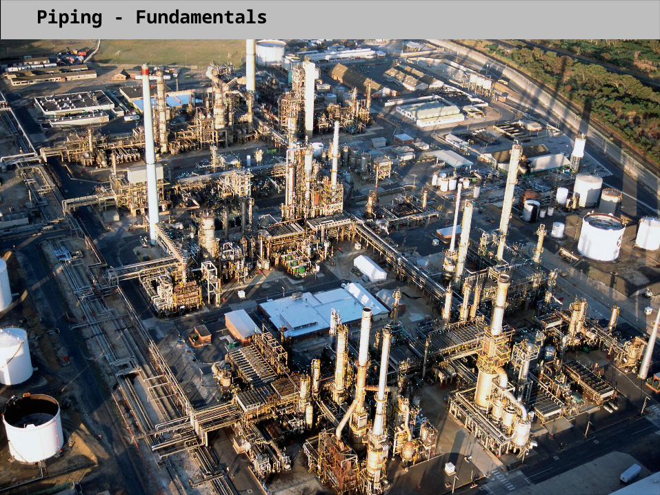
Piping - Fundamentals

Piping - Fundamentals
The Goal of Piping Engineering is:
To Ensure a connected Piping is……
Specified and Designed Fabricated and Erected Inspected and Tested Operated and Maintained
In other words….
To perform reliably and safely in all expected conditions, for its design life.

Piping - Fundamentals
Why is Piping Engineering so important?
Pipes are supported at point locations Weight of the Pipe may change Temperature will vary – ambient to operating Thermal expansion Connected to equipment Pipe are welded to components Different components within a piping system Etc…..

Piping Standards

Piping - Standards

Piping - Standards
Acronyms and Definitions
The following acronyms and definitions are applicable to this Guide. They may either appear in this Guide, or in various vendor valve catalogues. Understanding of these acronyms and what they mean may be necessary to proper valve selection.
ASME: The American Society of Mechanical Engineers. ANSI: American National Standards Institute. API: The American Petroleum Institute.
Process Pipe
Pipe is specified by its Nominal Bore, its outside diameter.Pipe is identified by its Wall Thickness, referred to as “Schedule”, eg Sch 40, 80, XS, etc

Piping - Specifications

Piping - Specifications

Piping - Specifications

Piping - Specifications

Piping - Specifications

Piping - Specifications
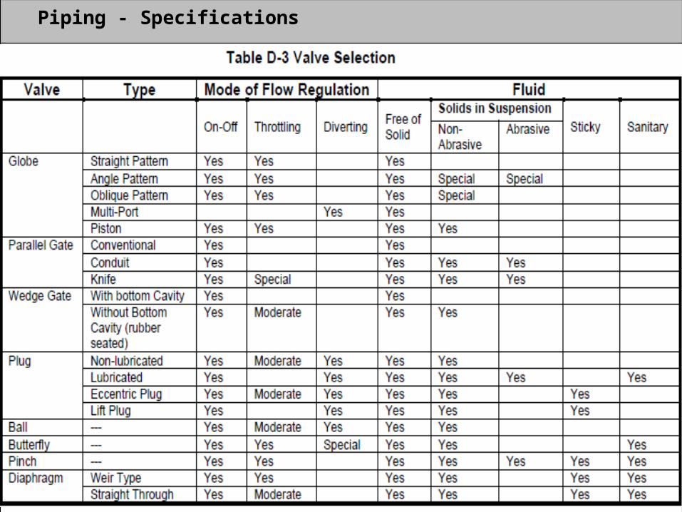
Piping - Specifications

Piping – Fittings and Components

Piping – Fittings and Components
Fittings are used in pipe systems to connect straight pipe or where change is direction is
required.
Ends are already prepared.
To adapt to different sizes, to branch out or re-direct the process (flow).
To provide a joint if 2 dissimilar materials are used in one system.
Fittings for pipe most often made from the same base material as the pipe being connected, e.g., carbon steel, stainless steel, copper or plastic.
Any material that is allowed by code may be used, but must be compatible with the other materials in the system, the fluids being transported, and the temperatures and pressures inside and outside of the system. Lines below 50mm NB are normally screwed or socket weld. Line 50mm and above are butt welded.

Piping - Flanges

Piping - Flanges

Piping - Flanges
Weld Neck flanges are used in critical applications. These are circumferentially welded onto the system at their necks which means that the integrity of the butt-welded area can easily be examined by X-ray radiography. The bores of both pipe and flange match thus reducing turbulence and erosion.

Piping - Flanges
Socket Weld Flange is counter-bored to accept the pipe, which is then fillet welded.The bore of both the pipe and the flange are the same to ensure good flows.

Piping - Flanges
Slip-on Flange is slipped over the pipe and then fillet welded. Easy to use infabricated applications.

Piping - Flanges
Screwed or Threaded Flange requires no welding and is used to connect otherthreaded components in low pressure non-critical applications.
Piping - Flanges
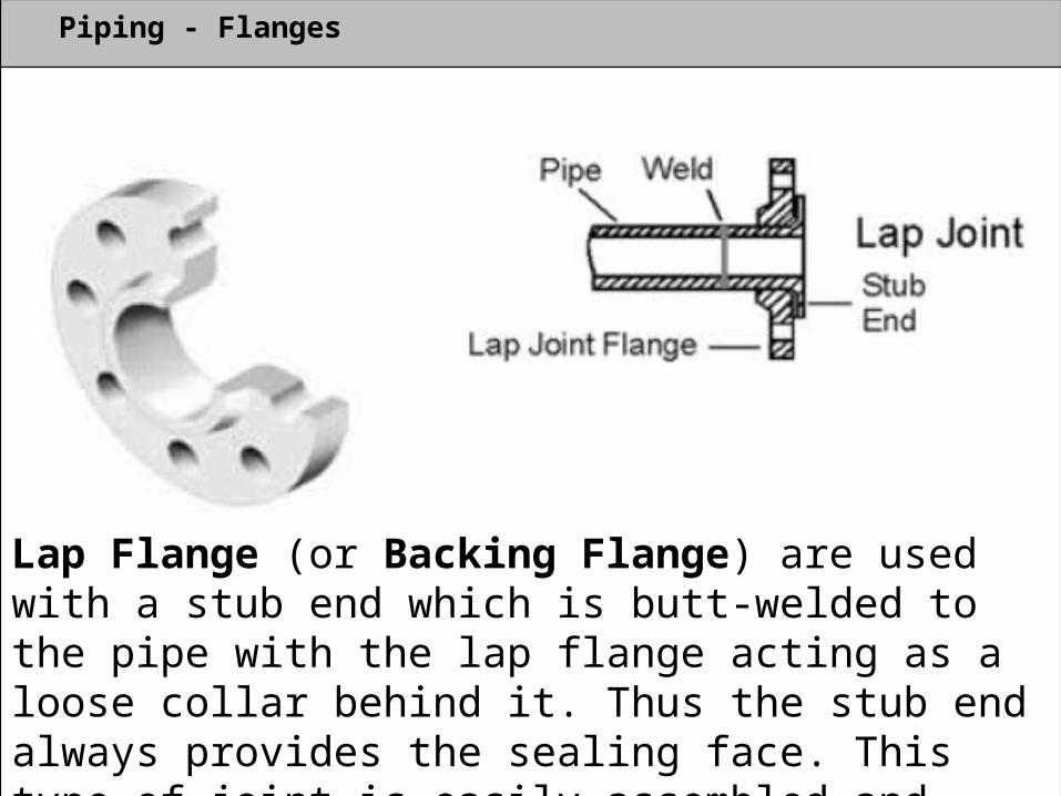
Lap Flange (or Backing Flange) are used with a stub end which is butt-welded to the pipe with the lap flange acting as a loose collar behind it. Thus the stub end always provides the sealing face. This type of joint is easily assembled andaligned, and it is favoured in low pressure applications.

Piping - Flanges
Blind Flange or sometimes called a Blanking Flange, this is used for blanking off pipelines, valves and pumps and as an inspection cover.

Piping - Valves

Piping - Valves A valve is a mechanical device that controls the flow of fluid and pressure within a system or process. A valve controls system or process fluid flow and pressure by performing any of thefollowing functions: Stopping and starting fluid flow. Varying (throttling) the amount of fluid flow. Controlling the direction of fluid flow. Regulating downstream system or process pressure. Relieving component or piping over pressure. There are many valve designs and types that satisfy one or more of the functions
identified above. A multitude of valve types and designs safely accommodate a wide variety of
process applications.
Complex control systems will use feedback from an instrument to controlthese types of valves to regulate pressure, temperature or flowrate dependingon the control parameters required.

Piping - Valves

Piping - Valves
Types of Valves Globe Gate Plug Ball Needle Butterfly Diaphragm Pinch Check Safety/relief Reducing

Piping - Valves
IsolationGate ValvesBall ValvesPlug ValvesPiston ValvesDiaphragm ValvesButterfly ValvesPinch Valves
Classification
RegulationGlobe ValvesNeedle ValvesButterfly ValvesDiaphragm ValvesPiston ValvesPinch Valves
Non-ReturnCheck Valves
Special PurposeMulti-port ValvesFloat ValvesBlind Valves

Piping - Valves
Rising Stem

Piping - Valves
Non Rising Stem

Piping - Valves
Gate Valve

Piping - Valves
Globe Valve

Piping - Valves
Ball Valve

Piping - Valves
Plug Valve

Piping - Valves
Diaphragm Valve

Piping - Valves
Reducing Valve

Piping - Valves
Butterfly Valve

Piping - Valves
Needle Valve
Piping - Valves
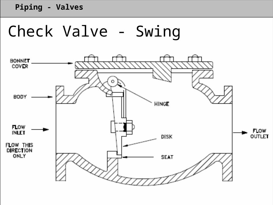
Check Valve - Swing

Piping - Valves
Check Valve - Tilting

Piping - Valves
Check Valve - Lift

Piping - Valves
Relief Valve

Piping – Piperack Configuration
Piperack configuration

Piping – Piperack Configuration
Piperack configuration

Piping – Pump arrangement and piping
Centrifugal Pump

Piping – Pump arrangement and piping
Typical pump locations - elevation

Piping – Pump arrangement and piping
Typical pump suction and discharge piping

Piping – Pump arrangement and piping
Orientation of handwheels

Piping – Pump arrangement and piping
Typical auxilliary pump piping

Piping – Pump arrangement and piping Maintenance and operation access requirements
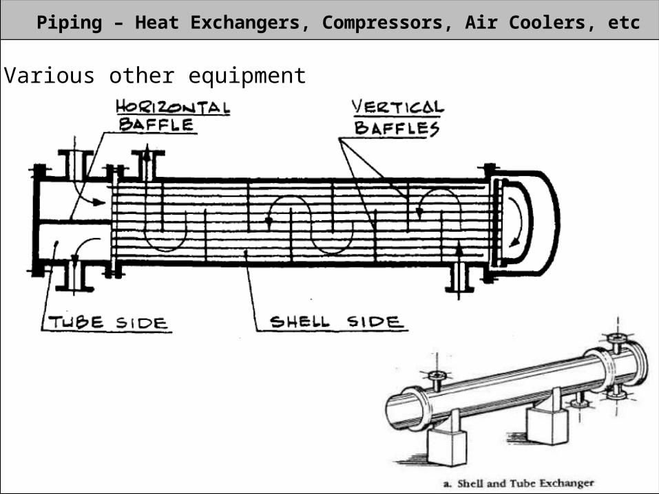
Piping – Heat Exchangers, Compressors, Air Coolers, etc Various other equipment

Piping – Pipe supports
Pipe Hangers

Piping – Pipe supports
Pipe Supports
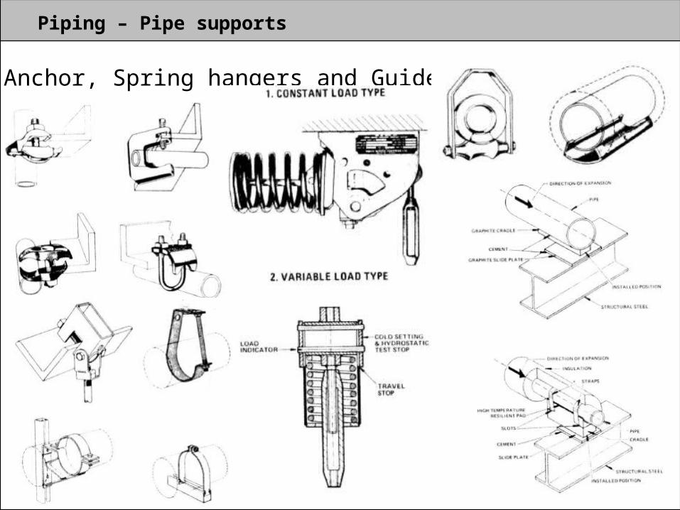
Piping – Pipe supports Anchor, Spring hangers and Guides

Outputs from the Piping Discipline
1. Overall plot plans showing location of various process units, offsite, package units,
roads, piperacks, sleepers, etc.2. PMS (Piping Material Specifications) & Valve Material Specifications.3. Equipment general arrangement layouts/drawings indicating the location of all the
equipment within a unit, platforms, ladders, overhead crane elevation.4. Piperack general arrangements drawings & structures for equipment support.5. Piping general arrangement layouts/drawings showing all the piping and
equipment.6. Piping BOM (Bill of Material).7. Piping stress analysis reports for critical lines.8. Drawing showing the vessel cleats location for pipe supports.9. Layout for underground services.10. Piping isometrics with bill of material.11. Pipe support location plan, support schedules, pipe support drawings.12. Purchase specification for insulation, painting, wrapping and coating.
Material Control
Piping Material ControlThe material controller is responsible for all piping material requirement planning. This includes quantity take-off activities, production of bill of material, piping material quantity summaries, piping requisitions, piping order bit tabulation/summaries and technical comparison and required at site date planning.The list of deliverables may include the following. - Bill of material for each piping documents - Bill of material summary - Special take-off summaries (large diameter or long delivery valves) - Piping material procurement request for quote (RFQ) draft - Piping material procurement purchase order (PO)

Electrical
Electrical engineering Responsible for all of the project power, lighting and communication needs. - Normal and emergency systems - hardware selection such as transformers and switchgear - Aboveground and underground distribution systems - electrical design considerations and electrical code requirements

Instrumentation
Instrument engineering Responsible for the ‘nervous’ system of the plant. Input is preliminary data sheet originated by process and complete the definition requirements, including final sizing and vendor selection. Other responsibilities are: - layout of any control room - control system hardware - control system software - local indicators - sensing elements and circuits - defining the physical hardware elements that constitute the in-line and on-line instruments for the project.


![[Vibrations] Fundementals of Mechanical Vibration_mcgraw_hill](https://static.fdocuments.in/doc/165x107/577c843f1a28abe054b81b22/vibrations-fundementals-of-mechanical-vibrationmcgrawhill.jpg)