Process Flow Diagrams REFINERY PROCESS · REFINERY— PROCESS FLOW DIAGRAMS 5 Process Flow Diagrams...
23
1 Process Flow Diagrams — Refinery REFINERY PROCESS Process Flow Diagrams Experience In Motion DECEMBER 2019
Transcript of Process Flow Diagrams REFINERY PROCESS · REFINERY— PROCESS FLOW DIAGRAMS 5 Process Flow Diagrams...

1 Process Flow Diagrams — Refinery
REFINERY PROCESS Process Flow Diagrams
Experience In Motion
DECEMBER 2019

REFINERY— PROCESS FLOW DIAGRAMS
2 Process Flow Diagrams — Refinery
Three Basic Refinery Process Flows
CONVERSIONSEPARATION STORAGE AND BLENDING
Crude
Gasoline
Gas
Naphtha
Kerosene
Fuel Oil
Residual/Asphalt
Separation Crude Oil into Various Fractions Based on Boiling Point• Crude Desalter• Atmosphere Crude Unit• Vacuum Crude Unit
Converts Lower Value Products into High-Demand, Premium Products• Residual Conversion• Middle Distillate Upgrading• Light Ends Processing
Combines the Various Components from the Conversion Processes into End-Use Products
BLEN
DING

REFINERY— PROCESS FLOW DIAGRAMS
3 Process Flow Diagrams — Refinery
Key Refinery Processes and Marketable End Products
REFINERY— PROCESS FLOW DIAGRAMS
4 Process Flow Diagrams — Refinery
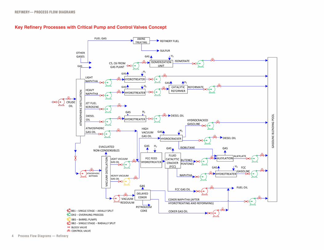
Key Refinery Processes with Critical Pump and Control Valves Concept

REFINERY— PROCESS FLOW DIAGRAMS
5 Process Flow Diagrams — Refinery
Conversion Process — Typical Distillation Unit Process Desciptions
One of the other feedstocks to a refinery is hydrogen, which can be used in a hydrotreater, isomerization, FCC, reformer, and a complex, capital-intensive unit.

REFINERY— PROCESS FLOW DIAGRAMS
6 Process Flow Diagrams — Refinery
Vapor or Flare Examples Using SIHI Vacuum Products Throughout the Refinery
Typical Vacuum Pump Package

REFINERY— PROCESS FLOW DIAGRAMS
7 Process Flow Diagrams — Refinery
Detailed Crude Distillation Process with Second-Phase, High-Vacuum Tower

REFINERY— PROCESS FLOW DIAGRAMS
8 Process Flow Diagrams — Refinery
Vacuum Distillation Unit (VDU), Enhanced with SIHI Vacuum Systems Options

REFINERY— PROCESS FLOW DIAGRAMS
9 Process Flow Diagrams — Refinery
Basic Delayed Coking Unit

REFINERY— PROCESS FLOW DIAGRAMS
10 Process Flow Diagrams — Refinery
Basic Hydrotreater

REFINERY— PROCESS FLOW DIAGRAMS
11 Process Flow Diagrams — Refinery
Typical Fluid Catalytic Cracker

REFINERY— PROCESS FLOW DIAGRAMS
12 Process Flow Diagrams — Refinery
Typical Hydrocracker Thermal and Pressure Balance Processes

REFINERY— PROCESS FLOW DIAGRAMS
13 Process Flow Diagrams — Refinery
Hydrocracker (Simplified)

REFINERY— PROCESS FLOW DIAGRAMS
14 Process Flow Diagrams — Refinery
Continuous Catalytic Reformer (Simplified)

REFINERY— PROCESS FLOW DIAGRAMS
15 Process Flow Diagrams — Refinery
Continuous Bed Process Flow with Primary Control Valves

REFINERY— PROCESS FLOW DIAGRAMS
16 Process Flow Diagrams — Refinery
Typical Alkylation-Unit Flow

REFINERY— PROCESS FLOW DIAGRAMS
17 Process Flow Diagrams — Refinery
Vapor Recovery System Process

REFINERY— PROCESS FLOW DIAGRAMS
18 Process Flow Diagrams — Refinery
Typical Vacuum Systems
PRESSURE CONTROL VALVE (Valtek MaxFlo 4)

REFINERY— PROCESS FLOW DIAGRAMS
19 Process Flow Diagrams — Refinery
Typical SIHI Liquid Ring Used in Flare Gas

REFINERY— PROCESS FLOW DIAGRAMS
20 Process Flow Diagrams — Refinery
Blending (Mixing) Flow with Key Pump and Control Valves

REFINERY— PROCESS FLOW DIAGRAMS
21 Process Flow Diagrams — Refinery
Typical Amine Treating Process in Refineries

REFINERY— PROCESS FLOW DIAGRAMS
22 Process Flow Diagrams — Refinery
Deasphalter (Simplified)

Flowserve Corporation5215 North O’Connor BoulevardSuite 2300 Irving, Texas 75039flowserve.com
North America
Latin America
Europe
Middle East
Africa
Asia-Pacific
FLS-1013-Diagrams (E/AQ) ASG-Refining, December 2019 © 2019 Flowserve Corporation. All rights reserved. Kämmer, Logix, NAF, Valbart, Valtek, Flowserve, and the Flowserve design are registered marks of Flowserve Corporation. All other marks are the property of their respective owners.