Proceedings of the Twelfth International Conference on...
4
THE BEAM DIAGNOSTICS OF THE MILAN KBOO CYCLOTRON E. Acerbi, G. Raia*, G.C. Rivoltella, L. Rossi * Laboratorio Nazionale del Sud - INFN - Catania Laboratorio L.A.S.A. Via F.lli Cervi 201 20090 Segrate (Mi) Italy INFN - Sezione di Milano Universita' degli Studi di Milano ABSTRACT The particle and energy flexibility and the compac tedness of the Milan superconducting cyclotron ha= ve required some special solutions for the beam diagnostics design. This paper presents in details the main features of the current probes, suitable for radial and axi al beam injection, for beam centering and extrac= tion and for beam dynamics control. A special care has been put on the design of a non intercepting beam phase probe system which would make easier the commissioning of the accelerator and would assure in future a good reliability and reprodu- cibility of the beam quality. 1. INTRODUCTION In the classical cyclotrons the beam diagnostics is not very sophisticated during the initial tests of the accelerator and becomes more complex in the following when it is used to control the beam qua- lity and to assure the tuning of the machine. For an heavy ion cyclotron a complete system of devi- ces for beam diagnostics is necessary during the commissioning because it is an indispensable tool for the setting of an accelerator which has a broad spectrum of particles and energies (1-3). If the heavy ion accelerator is a compact super- conducting cyclotron it is almost compulsory the design of the internal beam diagnostics in the fi- nal configuration from the beginning of the pro- ject because the constraints arising from the clo sed structure of the magnet and cryostat and from the compactedness of the pole region make very dif ficult every unforeseen change. - In the case of K = BOO Milan superconducting cyclo tron the main elements of the internal beam diagno stics are constituted by current probes of diffe= rent types (movable or fixed, integral or differen tial, fully or partially beam intercepting) and by fixed and capacitive phase probes. Their installa- tion in the acceleration chamber of the cyclotron has required some particular solutions due to limi ted available space and accessibility. Indeed the= se elements can be installed only on the hills be- cause the valleys are completely taken up by dees and cryogenic pumps. The radial access to two hills is forbidden by the presence of the electro- static deflectors which cover azimuthally and axially the whole hill sector. The large spiral an gle of the sectors prevents the use of radial move ments from the center to the extraction radius by making more difficult the positioning and cooling of the current probes. At last the design of the probes and supports must consider that the availa- ble gap is 25 mm high (the overall dimensions of the equipment can reach about 35 mm) and the upper pole can be lifted (about 1.B m) in order to allow the access to the acceleration chamber. The layout of the final beam diagnostics system is illustrated in Fig. 1. The diagnostics system con- sists of the following equipments: a movable probe (1) with interchangeable heads for different functions (beam current measure- ments, beam phase measurements, burst length measurements) in order to study the features of the acceleration process. four fixed current probes (2) put on or off the beam in order to verify the beam centering. four movable differential probes (3) distribu- ted along the particle extraction path. four beam profile monitors (4) in order to con- trol the beam trajectory during the radial in- jection from Tandem or during the axial injec- tion from ECR source. sixteen fixed and non destructive phase probes (5) in order to make easier the setting and tu ning of the accelerator. This paper will describe the main features of the- se equipments by emphasizing those aspects and tho se technical solutions which have been determined by the compact configuration of the superconduc- ting cyclotron. 2. THE MOVABLE MULTI-HEAD PROBE. This probe moves along the median spiral line of the hill by covering the whole acceleration range and it can be brought completely outside the va- cuum chamber and isolated with a valve for head changes or maintenance. The movement of the probe is accomplished by means of a train whose rails are screwed to the copper liner and whose carria- ges are connected with a CuBe sheet in order to as sure articulated joints without mechanical The train is driven by a stepping motor with a ma- ximum speed of 10 mm/s: its absolute position is measured with a precision of 0.1 mm by means of Proceedings of the Twelfth International Conference on Cyclotrons and their Applications, Berlin, Germany 283
Transcript of Proceedings of the Twelfth International Conference on...

THE BEAM DIAGNOSTICS OF THE MILAN KBOO CYCLOTRON
E. Acerbi, G. Raia*, G.C. Rivoltella, L. Rossi * Laboratorio Nazionale del Sud - INFN - Catania
Laboratorio L.A.S.A. Via F.lli Cervi 201 20090 Segrate (Mi) Italy INFN - Sezione di Milano Universita' degli Studi di Milano
ABSTRACT The particle and energy flexibility and the compac tedness of the Milan superconducting cyclotron ha= ve required some special solutions for the beam diagnostics design. This paper presents in details the main features of the current probes, suitable for radial and axi al beam injection, for beam centering and extrac= tion and for beam dynamics control. A special care has been put on the design of a non intercepting beam phase probe system which would make easier the commissioning of the accelerator and would assure in future a good reliability and reproducibility of the beam quality.
1. INTRODUCTION In the classical cyclotrons the beam diagnostics is not very sophisticated during the initial tests of the accelerator and becomes more complex in the following when it is used to control the beam quality and to assure the tuning of the machine. For an heavy ion cyclotron a complete system of devices for beam diagnostics is necessary during the commissioning because it is an indispensable tool for the setting of an accelerator which has a broad spectrum of particles and energies (1-3).
If the heavy ion accelerator is a compact superconducting cyclotron it is almost compulsory the design of the internal beam diagnostics in the final configuration from the beginning of the project because the constraints arising from the clo sed structure of the magnet and cryostat and from the compactedness of the pole region make very dif ficult every unforeseen change. -In the case of K = BOO Milan superconducting cyclo tron the main elements of the internal beam diagno stics are constituted by current probes of diffe= rent types (movable or fixed, integral or differen tial, fully or partially beam intercepting) and by fixed and capacitive phase probes. Their installation in the acceleration chamber of the cyclotron has required some particular solutions due to limi ted available space and accessibility. Indeed the= se elements can be installed only on the hills because the valleys are completely taken up by dees and cryogenic pumps. The radial access to two hills is forbidden by the presence of the electrostatic deflectors which cover azimuthally and
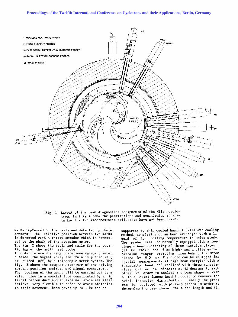
axially the whole hill sector. The large spiral an gle of the sectors prevents the use of radial move ments from the center to the extraction radius by making more difficult the positioning and cooling of the current probes. At last the design of the probes and supports must consider that the available gap is 25 mm high (the overall dimensions of the equipment can reach about 35 mm) and the upper pole can be lifted (about 1.B m) in order to allow the access to the acceleration chamber. The layout of the final beam diagnostics system is illustrated in Fig. 1. The diagnostics system consists of the following equipments:
a movable probe (1) with interchangeable heads for different functions (beam current measurements, beam phase measurements, burst length measurements) in order to study the features of the acceleration process. four fixed current probes (2) put on or off the
beam in order to verify the beam centering. four movable differential probes (3) distribu
ted along the particle extraction path. four beam profile monitors (4) in order to con
trol the beam trajectory during the radial injection from Tandem or during the axial injection from ECR source. sixteen fixed and non destructive phase probes
(5) in order to make easier the setting and tu ning of the accelerator.
This paper will describe the main features of these equipments by emphasizing those aspects and tho se technical solutions which have been determined by the compact configuration of the superconducting cyclotron.
2. THE MOVABLE MULTI-HEAD PROBE. This probe moves along the median spiral line of the hill by covering the whole acceleration range and it can be brought completely outside the vacuum chamber and isolated with a valve for head changes or maintenance. The movement of the probe is accomplished by means of a train whose rails are screwed to the copper liner and whose carriages are connected with a CuBe sheet in order to as sure articulated joints without mechanical plays~ The train is driven by a stepping motor with a maximum speed of 10 mm/s: its absolute position is measured with a precision of 0.1 mm by means of
Proceedings of the Twelfth International Conference on Cyclotrons and their Applications, Berlin, Germany
283
C2
C1B
1) MOVABLE MULTI-HEAD PROBE
2) FIXED CURRENT PROBES
3) EXTRACTION DIFFERENTIAL CURRENT PROBES
4) RADIAL INJECTION CURRENT PROBES
5) PHASE PROBES
YOKE //
M2
M6
"
M5
M3
M4
Fig. 1 Layout of the beam diagnostics equipments of the Milan cyclotron. In this scheme the penetrations and positioning apparata for the two electrostatic deflectors have not been drawn.
marks impressed on the rails and detected by photo sensors. The relative position between two marks is detected with a rotary encoder which is connected to the shaft of the stepping motor. The Fig. 2 shows the train and rails for the positioning of the multi head probe. In order to avoid a very cumbersome vacuum chamber outside the magnet yoke, the train is pushed in ( or pulled off) by a telescopic screw system. The Fig. 3 shows the compact structure of the driving motors, position monitors and signal connectors. The cooling of the heads will be carried out by a water flow in a coaxial tube constituted by an in ternal teflon duct and an external stainless steel bellows very flexible in order to avoid obstacles to train movement. beam power up to 1 kY can be
supported by this cooled head. A different cooling method, consisting of an heat exchanger with a liquid of low boiling temperature is under study. The probe will be normally equipped with a four fingers head consisting of three tantalum plates (11 mm thick and 6 mm high) and a differential tantalum finger protuding from behind the three plates by 0.5 mm. The probe can be equipped for special measurements at high beam energies with a tomography head (4) realized with three tungsten wires 0.1 mm in diameter at 45 degrees to each other in order to analyse the beam shape or with a four axial finger head in order to measure the axial intensity distribution. Finally the probe can be equipped with pick-up probes in order to determine the beam phase, the bunch length and ti-
Proceedings of the Twelfth International Conference on Cyclotrons and their Applications, Berlin, Germany
284

Fig. 2 The train and the rails of the multihead probe. The probe is equipped with a four finger head.
Fig. 3 Drive mechanism of the multi-head probe.
me structure of the last turns and of the extracted beam.
3. THE FIXED CURRENT PROBES. In order to control the beam centering three probes are necessary. In the Milan cyclotron, as previously explained it is impossible to have three movable probes, for this reason two couples of current probes at two fixed radii have been installed on the liner. They are located at about 120 degrees from the movable multi-head probe and respectively at the radii Rl = 0.38m and R2 =
0.623m. The probes are normally out the beam (Fig. 4a) and are put on the beam by means of a short current pulse (I 25 A t = 0.5 s) in an insulated bar inserted at the bottom of the probe. Because of the Lorentz force acting on the bar the probe pivots and reaches a stable vertical position (Fig. 4b). By reversing the current pulse the pr~ be returns in the horizontal position. These probes, whose tantalum heads are 5 mm large and 10 mm thick, can support a beam power of about 50 Y with a maximum temperature of 700 C.
=. a
, b
Fig. 4 Prototype of the fixed probe. The head is put on or off the beam [picture b) or picture a») by the Lorentz force.
4. MOVABLE DIFFERENTIAL CURRENT PROBES FOR BEAM EXTRACTION.
The beam extraction is carried out in about 270 degrees and requires two electrostatic deflectors and seven magnetic channels whose positions must be adjusted to different ions and energies. In order to check the position and the radial width of the beam along the extraction trajectory four differential probes will be installed just in front of the magnetic channels. The Fig. 5 shows the support and the independent drive mechanisms of the magnetic channel and the current probe. The tantalum heads (0.5 mm large and 5 mm thick) are not water cooled and have been designed in order to stop all the ions from Carbon to Uranium and to evacuate by radiation the beam power. The Fig. 6 shows the details of a dummy probe (made in perspex) with the magnetic channel as seen from the beam. It is under study the possibility to install in front of the first electrostatic deflector a differential current probe which is put on or off the beam by a system of gears. The mechanical problem is complicated but it can be solved, the RF power picked-up by this probe represents the true difficult problem.
Proceedings of the Twelfth International Conference on Cyclotrons and their Applications, Berlin, Germany
285

Fig. 5 Support and drive mechanism of the extraction differential current probe.
5. MOVABLE DIFFERENTIAL CURRENT PROBES FOR INJEC-TION.
For the median plane injection from Tandem an inte gral-differential probe, water cooled, is instal: led in the cyclotron yoke. In order to verify that the beam is correctly transported on the stripper, a differential current probe will be inserted in the equipment for the stripping foil (5) positioning . For the axial injection a special device which can monitor the ion beam at the entry and exit of the electrostatic inflector is under study.
6. THE PHASE PROBE SYSTEM. Both passive probes (low input impedance) and acti ve probes (broad band input amplifier directly con nected to the high impedance pick-up plate) have been used in several laboratories (6-10). In our case passive pick-up probes have been chosen because they present some advantages like continuous and easy access to the electronic components, more precise comparative absolute measurements between
Fig. 6 Details of the extraction current probe. Behind the head there is the entry of the magnetic channel.
p~obes and no unwanted effect by radiation damage. SIxteen phase probes has been installed on the liner of two successive hill sectors. The first probe is installed at R1 = 0.331m whereas the last one is located at R16 = 0.886 m (the ion extraction radius is ranging from 0.85m to 0.87 m). The other probes are distributed with a quadratic law of the radius in order to have the same energy (or turns) increments between successive probes. The last phase probe in the first hill sector and the first phase probe in the second hill are located at the same radius in order to assure an overlapping between the phase values measured by the two sets of probes. The lower and upper pick up plates are connected to an external RF multiplexer and processing chain by means of coaxial cable through flanges on the liner and on the pole caps. This solution allow the lift of the upper cap to have access to acceleration region without disconnecting the phase probe system. The characteristics and the design of the phase probes and electronics are presented in another paper (11)
7. ACKNOWLEDGEMENT. The authors wish to express their thanks to M. C. Gesmundo and to M. S. Passarello for their technical support in the beam diagnostics engineering.
8. REFERENCES. 1) F.Loyer et al. Proc. of 9th ICCA, 585 Caen
(1981) 2) S.Schneider et al. Proc. of 11th ICCA, 453
Tokyo (1986) 3) M. Kase et al. Proc. of 11th ICCA, 443
Tokyo (1986) 4) S. Adam et al. Proc. of 10th ICCA, 23
East Lansing (1984) 5) E.Acerbi et al. Proc. of 11th lCCA, 168
Tokyo (1986) 6) W. Brautigam et al. IEEE Trans. on Nuclear
Science vol. NS-26 n. 2, 2375 (1979) 7) G.C.L. van Heusden et al. IEEE Trans. on Nu
clear Science vol. NS-26 n. 2, 2209 (1979) 8) R.J.Vader and H.W.Schreuder IEEE Trans. on
Nuclear Science vol. NS-26 n. 2, 2205 (1979) 9) R.Burge and R.Vader Proc. of 9th ICCA, 593
Caen (1981) 10) Y.Sato et al. Proc. of 9th lCCA, 597 Caen
(1981) 11) E. Acerbi et al. "Conceptual design and tests
on the phase probes at Milan K800 cyclotron" presented at this Conference
Proceedings of the Twelfth International Conference on Cyclotrons and their Applications, Berlin, Germany
286