PROCEEDINGS OF THE CONFERENCE ON … OF THE CONFERENCE ON FRACTURED AND JOINTED ROCK MASSES LAKE...
8
PROCEEDINGS OF THE CONFERENCE ON FRACTURED AND JOINTEDROCKMASSES LAKE TAHOE/CALIFORNIA/USA/3-S JUNE 1992 Edited by L.R.MYER & C.-RTSANG Lawrence Berkeley Laboratory California, USA N.G.W:COOK & R.E.GOODMAN University of California, Berkele)\ USA OFFPRINT . " . A.A. BALKEMA/RO1TERDAM/BROOKFIELD/ 1995
Transcript of PROCEEDINGS OF THE CONFERENCE ON … OF THE CONFERENCE ON FRACTURED AND JOINTED ROCK MASSES LAKE...

PROCEEDINGS OF THE CONFERENCE ON FRACTURED AND JOINTED ROCK MASSESLAKE TAHOE/CALIFORNIA/USA/3-S JUNE 1992
Edited by
L.R.MYER & C.-RTSANGLawrence Berkeley Laboratory California, USA
N.G.W:COOK & R.E.GOODMANUniversity of California, Berkele)\ USA
OFFPRINT
."
.
A.A. BALKEMA/RO1TERDAM/BROOKFIELD/ 1995

Fractured and Jointed Rock Masses, Myel; Cook, Goodman & Tsang (eds)@ 1995Ba/kema, Rotterdam./SBN90S410S917
Application of block theory and the critical key block concept to tunneling:
1\vo case histories
Yossef Hatzor & Richard E. GoodmanDepartment of Civil Engineering, University of California, Berkele)\ Calif:, USA
Abstract
This paper describes a new technique for applicationof Block Theory [IJ in highly discontinuous rock massenvironments. The technique is applicable for both tunnel and
rock slope engineering. It is based on the empiricalobservation that several critical key blocks control the entireblock failure pattern in a given rock structure and excavationgeometry. Using this technique one can predict the most likelyblocks to fail during excavation in advance. prior to actualconstruction, on the basis of readily available geological data.
behind an excavation free face, Block Theory determinesrigorously which of the existing half space combinations willcreate a removable block, what will be its mode of failure, andwhat would be the required support pressure to keep the blockin place. Such a powerful tool is handy whenever a welldetermined problem is at hand and wherever the geometry isclearly defined. When the rock structure becomes morecomplex and a predicted rock behavior is required, applicationof the theory is no longer straight forward and a great deal ofengineering judgement must be invoked
In this paper a technique for application of BlockTheory in complex rock environments is presented. Thistechnique, described here as The critical key block concept,attempts to predict the most likely block failures to beencountered during excavation. It uses a joint setcharacterization of the rock mass with preferred setorientations, the relative spacing of the joint sets, and thecorresponding friction angles. A Block Theory removabilityanalysis is built in the technique, as well as a limit equilibriumanalysis that is often used in Block Theory applications. Thevalidity of the critical key block concept has been tested so farin several underground excavation projects as well as rockslope excavations. Preliminary results were reported byGoodman and Hatzor [7] and Hatzor and Goodman [8]. In thispaper the validity of the technique is demonstrated by meansof an analysis of two case histories. In these cases a fullapplication of the critical key block concept is made on thebasis of geological exploration data. The predictions arecompared with actual block failures that took place followingconstruction.
I. INTRODUCTION
ll. METHOD OF INVESllGAllON
A. Analysis
The input data for the analysis include theorientation, spacing and frictional resistance of thediscontinuity sets, and the orientation of the excavation freeface. The analysis outputs the following:
a. A list of all the possible Joint Combinations withinthe global structure of the rock mass.
b. A Block Theory re/1wvability analysis. For eachjoint combination the removable Joint Pyramid (JP) is found,with respect to the analyzed free surface, using Shi's Theorem[I]. Some joint combinations are detected as non hazardous at
Traditional engineering in discontinuous rock masseshas been largely based on empirical rock mass classificationmethods. The output of such methods has typically been in theform of rock load assessments [2]. active span stand up time[3], or overall rock quality grade [4,5,6]. Since these methodshave been introduced they have been tested and modifiedextensively. Through the years, a vast empirical data base hasbeen accumulated and correlations between the variousmethods have been proposed. Such correlations developed intodesign charts that provided the estimated support pressures forrocks of different quality and excavations of different geome-try. Today such design charts provide the rock engineer witha powerful design tool that has been tested and used for a longperiod of time and is therefore considered reliable.
The commonly used rock mass classification methodshowever largely ignore particular stability problems that mayarise due to the formation of frequently occurring removableblocks behind the excavated free face. Such blocks maycontrol the overall behavior and indeed may result in largefailures. The factors that influence the formation of suchpotentially unsafe zones behind the free face are not necessari-ly correlated with a so called rock quality grade. Rather, suchfailures are a consequence of the interaction between theparticular rock structure and the excavation geometry. Similarblocks may form when the lithology is changed from weaksedimentary rocks to strong crystalline rocks for exatnple, aslong as the overall rock structure and the excavation geometrydo not change.
Block Theory [I] provides a mathematical formulationthat enables the engineer to relate the rock structure to theexcavation geometry. For any number of joint intersections
66~

this stage of the analysis as their corresponding removable JPhas an edge that plots on or near the free face, or has no modeof failure.
c. The lC probability P(JC). This figure assignsprobabilities for the occurrences of the various JC's in therock mass; the governing factor is the frequency of theindividual joint sets in the rock mass and their orientations.
d. The lP shape parameter [K]. A parameter that iscomputed for each removable JP of each JC. This figureassigns numerical values to the different removable JP'saccording to their respective shapes. It is based on theobservation that the JP shape has an effect on the degree offreedom it has to slide out of the rock. The governing factorin this figure is the sum of the internal angles between the JP
planes.
the blocks are perfectly preserved within the mould and onecan measure their attitudes. Thus by measuring the attitudes ofthe joints at the boundary of each mould, the geometry of thefailed block is revealed. The analysis of each mould that wasfound include the following:1. Measurement of the boundary joints and orientation of thefree face in the particular location.2. Block theory removability analysis using the mould joints asinput in order to confirm the removable JP, the observed halfspace combination, and the failure mode.3. Correlation of each boundary joint in the mould with theglobal joint sets in order to assign the correct jointcombination to the observed block failure.
Once all failed blocks are correlated with thecorresponding joint combination, a comparison between thepredicted failure likelihood and actual failures for each jointcombination is made possible.
e. The JP instability parameter [F]. This figureutilizes the sliding force F, that is required to keep the IP inplace ( see derivation in [I]. chapter 9). and is based on a limitequilibrium analysis. The sliding force computation requiresthe friction angle of the sliding surface/s, the density of therock mass and the direction and magnitude of the resultantforce.
III. THE CRITICAL KEY BLOCK METHOD OF ANALYSIS
The critical block method of analysis involves all thesteps that were mentioned above. A detailed description of theprocedure is given by Hatzor and Goodman [8]. Here only theprincipal points will be discussed.
A. The joint combination probability P(iC)
A Joint Combination (JC) was defined as a subsystemof joint sets that intersect over a small region in space. Allcombinations of joints do not have the same likelihood ofpassing through the same small volume; in particular, a jointset that exhibits a close spacing has a greater likelihood ofintersecting any given volume, and vice versa. The probabilitythat a joint of a given set intersects a line of length interval[x] is determinable if the probability density function for thespacing of the joints is known. For the negative exponentialdistribution, recommended after examination of field data byPriest and Hudson [9], Hudson and Priest [10] and Wallis andKing [11], the probability density function is expressed by:
f(x) -).,e-Ax (1)
f. The relative block failure likelihood distributionP(B). This is the desired parameter of the analysis. It iscomputed for all JC's with respect to a single excavation freeface. The relative block failure likelihood of a single jointcombination is the product of its P(JC), [K] and [F] values.When P(B) is computed for all joint combinations adistribution results, the modes (high points) of which definethe critical blocks for the free face under consideration. ThusP(B) weighs the overall risk offered by each JC when a freeface of known orientation is excavated through the rock mass.P(B) is not a formal probability distribution function withvalues in the range of 0 to 1. Rather, it is a relative likelihoodwith numerical values ranging here from 0 to 2. Thesignificance of this distribution is in its relative rather then itsabsolute values. Using this distribution one can select thecritical blocks for each free face of the excavation in the rockmass of concern. The design blocks for each free face areselected from the group of critical blocks.
The analysis assumes that it is meaningful to representthe structure of the rock mass by several prominent joint sets,each of which embraces a cluster of orientations. We modelthe behavior of the expected opening using combinations ofideal joint sets and ignore the combinations that may arisefrom the intersection of less common orientations. Thecorrectness of this method depends on the correctness of thisassumption; i.e. the analysis is invalid when joints are trulyrandom in the rock mass.
where the parnmeter A expresses the average frequency ofdiscontinuities per unit length; its inverse is the averagespacing between discontinuities. This distribution has oneparameter A; both the mean and standard deviation are equalto 1/A. If the discontinuity frequency is determined using ascan line survey then a Terzaghi correction [12] for the truefrequency must be used.
The discontinuities that intersect a scan-line are analogousto arrivals along a time-line. In this analogy. the scan-line isthe time-line. the discontinuities that intersect the scan-lineare the arrivals. and the spacing between discontinuities arewaiting times. If the distribution of the waiting times betweenarrivals is negative exponential. and if the waiting timesbetween each arrival are independent of previous arrivals. thenthe distribution of the number of joints N in a fixed intervalof length [x] is Poisson. Accordingly. the probabilitY ofencountering N = k joints from set i along an interval of
length [X;] along the scan-line in direction normal to the joint(oJ is determined by:
B. Field Investigation
In the field two pilot tunnels have been studied. Thetunnels were driven through crystalline and sedimentary rockswhere the structure played a major role in the failure patterns.In both tunnels a great number of blocks were released fromthe circumference of the excavation. either during theexcavation or at some point later in time. The blocks thatfailed could be traced on the parent rock wall in the form ofnwulds. These moulds were left behind in the rock after thefailed block was removed, leaving a "negative" picture of thefailed block. In competent rock masses the boundary joints of
~~;1
k-O,l.x>O
(2)
where the only required parameter is the joint set frequency Ai'
a rock mass property that can be obtained from a scan-line
survey. In practice we are interested in the case where there is
one intersections of joint set i along a very small interval [X;]
namely:
(3)P[N,-l] o - Art
Similarly we can express the Poisson probability for setsj and k of joint combination {i;j;k). Assuming these eventsto be independent, the probability of all three joint setsoccurring in the small lengths {[xJ,[X;J,[XkJ) is the product ofthe three independent probabilities :
JC: {N,-l} U {NJ-l} U {Nt.-i)p(JC) ~ P({N,-l}) 'P({NJ-l}) .P({Nk-l}) (4)p(JC) ~ ),~,'),I'J'),rk
Note that equation 4 depends on an assumed spacingdistribution, and that it does not incolporate the dependence ofthe probability on the orientation of the joints in the jointcombination. Mauldon [13] derived a more general expressionthat would fit any joint spacing distribution, which alsoaddresses the inherent dependence of the distribution on thejoint orientations:
p(JC) - (Ar,>(Ar;(A.r1'~v-
(5)
shape parameter weighs the degree of hazard offered by eachremovable IP. We distinguish between Open and Closed Ips.when we discuss the influence of the IP shape on its stability.An Open IP is characterized by large angles between its planeswhen measured inside the JP and a small apex distance formthe free face. whereas a closed IP is characterized by smallangles between the planes and a large apex distance from thefree face from which it is removable. Using field observationsit was found that the majority of the failed blocks had an openJP. There could be several reasons for this phenomena:a) Considering a circular tunnel cross section, as the apexdistance increases, the joint normals come closer to directionstangential to the free face, resulting in higher lateral stresseson the faces of the block.b) As the apex distance increases, the area of the sideplanes also increases and if the joint planes exhibit cohesion,a greater cohesive force resists sliding.c) As the apex distance increases, the permissible directions forblock movement become more constrained, and thestrengthening effect of joint roughness becomes pronounced.
A way to quantify the shape of a IP was discoveredand discussed by Mauldon [14] in his general solution to theprobability that a JP is removable. Here we use similarequations to find the risk offered by a IP that is known to beremovable (the removability of the IP is already established atthis stage of the analysis). Each IP has a particular sphericaltriangle area which reflects the value of the angles between itsplanes and thus its shape when only tetrahedral blocks areconsidered. Therefore, the area of a JP spherical triangleoffers a grade for the removable IP degree of hazard, wherethe greater the spherical triangle area, the greater the risk thatthe IP will produce actual block failures when cut by the freeface. The IP shape parameter [K] can be expressed as theratio of the IP spherical triangle area to the surface area of the
stereographic projection sphere:
K - (A + B + C - It )R2 (8)
47tR2where V;jk is the volume of the parallelepiped bounded by thepairs of planes formed by joints {ij,kl with normals(n"nJ,n.l, where each pair is separated by intervals [x;], [Xj]'[x.] respectively. The volume of the parallelepiped is given
by:
[xJ [x) [xJV -~k ba .,. X,. I
I J l'(6)
where A,B,C are the internal angles between the IP boundaryplanes for a JP with 3 joints. and R is the radius of the
stereographic projection sphere.
C. The JP Instability Parameter [F]
The JP instability parameter is a mapping of thesliding force required to keep the JP in place into a regionfrom 0 to 2 namely:
where. and x indicate dot and cross products respectively,and n, indicate a unit vector in the direction of the jointnormal. Inserting equation 6 into 5 we get Mauldon's equation:
p(JC) - (AjAJA~..nJxnJ (7) F - 2~J (9)-~ s iF) s 1
where F is the JP relative instability parameter and IF,I is themagnitude of the IP sliding force vector normalized by theblock weight. The sliding force is computed using limitequilibrium analysis procedures as discussed by Goodman andShi [1]. In their analysis a JP with a falling mode has slidingforce that is equal to the weight of the block and whennormalized by that weight it becomes + 1.0. representing themost dangerous case. For this sliding mode F equals 2. A IPat limit equilibrium has a sliding force of 0 and therefore an Fvalue of 1.0. A JP that is safe under the assumed friction
In our analysis we use MauIdon's generalized equation tocompute the joint combination probability.
B. The JP shape parameter {k]
The JP shape parameter [K] evaluates the likelihoodof a removable block to actually release from the excavationpyramid [I] using primarily kinematical considerations. Itdistinguishes between kinematically free and kinematicallyconstrained sliding vectors of different removable Ips. Thus the
665

HANGING LAKE TUNNELSGLENWOOD CANYON - COLORADO, USA
I~P(B) _lIfailures I
Figure 1: Comparison between predicted block failure likelihood for all hazardous joint combinations and actual blocks (moulds)
that were found in the field. Free face orientation is 90/330.
the excavation free face which is considered. The number ofunordered combinations of n joint sets taken k at a time is
given by:
(11)/IIN--Jc 11(/1-1)1
where the index k is the number of joint sets that comprise aIP. Considering tetrahedral blocks k is equal three, the fourthsurface being the free face of the excavation. We haveobserved in the field that the larger the value of k, the smallerthe recurrence of its JP's. IP's with k = 4 proved relativelyrare and JP's with k = 5 or more were not observed more thanonce.
The critical key block analysis process must berepeated for each excavation free face since each determinesparticular set of removable Ips. From the group of criticalblocks the design blocks for each excavation face are selected.The geometry of the design blocks and the excavation crosssection determine the selected support dimensions.
angles on the joints has a negative sliding force vector,meaning that the block must be pulled to be released form therock. The corresponding F value is smaller then I but greaterthen 0, A IP that has no mode, meaning that the JP will notslide even if a friction angle of zero degrees is assumed,represents an infinitely safe block with an F value of zero.
The F value considers the equilibrium condition of theblock, Note that only the net sliding force is used in equation9, Therefore, Equation 9 allows one to compute the IPinstability parameter for all removable Ips on the basis of thejoint geometry alone without consideration of actual blocksize; block size is controlled by the orientation of the free faceand the actual block that is formed within the maximumremovable block region. Like the JP density and shapeparameters, the JP instability parameter can be found on thebasis of the exploration data only and it can be used to weighthe risk offered by the different possible removable Ips.
D. The overall block failure likelihood P(B)
IV. TWO CASE mSTORlES
A. Hanging Lake Tunnels: tunneling through crystalline rocks
These two highway tunnels, driven through thePrecambrian basement rocks of Glenwood Canyon, Colorado,were investigated in the field following the completion of theexploratory tunnel excavation and during the construction ofthe full size opening. The tunnels were excavated throughhighly discontinuous but very competent crystalline rocks,consisting of migmatite gneiss and quartz diorite intruded inplaces by granite and pegmatite. The global structure of therock mass contributes open joints, faults and shears, andfoliation planes. Field investigations indicated that thegoverning mode of failure during or immediately followingconstruction was sliding of blocks along planes of pre-existingstructural discontinuities. Only very rarely did blocks fail due
Using the Joint Combination probability P(JC), the JPshape parameter (K) and the JP instability parameter (F) theoverall block fililure likelihood can be found for any jointcombination in the rock mass. This likelihood compares therelative risk offered by the different joint combinations in therock mass when a free face of fixed orientation is excavatedthrough it. For every single joint combination the block fililurelikelihood is given by:
P(B) - P(JC) [K] [1'1 (10)
where: P(B) = relative block/ailure likelihoodP(JC) = Joint Combination ProbabilityK = JP shape parameterF = JP instability parameter
The relative block failure likelihood is computed forall Jcs and thus a distribution of P(B) values for all Jcs isobtained, the modes of which indicate the critical blocks for
666
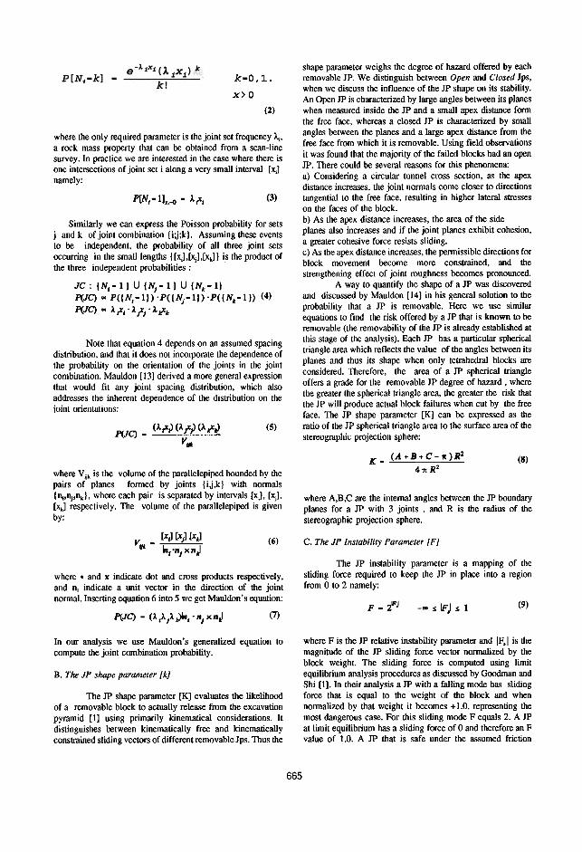
CUMBERLAND GAP TUNNELKentucky-Tennessee, USA
Figure 2: Comparison between predicted block failure likelihood for all joint combinations and actual blocks (moulds) that were
found in the field. Free face orientation: 90(213.
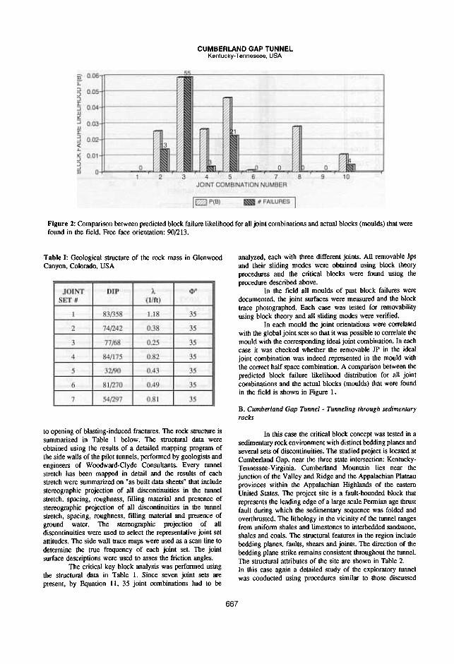
Table I: Geological structure of the rock mass in GlenwoodCanyon, Colorado, USA
analyzed. each with three different joints. All removable Jpsand their sliding modes were obtained using block theoryprocedures and the critical blocks were found using theprocedure described above.
In the field all moulds of past block failures weredocumented. the joint surfaces were measured and the blocktrace photographed. Each case was tested for removabilityusing block theory and all sliding modes were verified.
In each mould the joint orientations were correlatedwith the global joint sets so that it was possible to correlate themould with the corresponding ideal joint combination. In eachcase it was checked whether the removable JP in the idealjoint combination was indeed represented in the mould withthe correct half space combination. A comparison between thepredicted block failure likelihood distribution for all jointcombinations and the actual blocks (moulds) that were foundin the field is shown in Figure 1.
B. Cumberland Gap Tunnel - Tunneling through sedimentary
rocks
to opening of blasting-induced fractures. The rock structure issummarized in Table I below. The structural data wereobtained using the results of a detailed mapping program ofthe side walls of the pilot tunnels. performed by geologists andengineers of Woodward-Clyde Consultants. Every tunnelstretch has been mapped in detail and the results of eachstretch were summarized on ''as built data sheets" that includestereographic projection of all discontinuities in the tunnelstretch, spacing, roughness, filling material and presence ofstereographic projection of all discontinuities in the tunnelstretch, spacing, roughness, filling material and presence ofground water. The stereographic projection of alldiscontinuities were used to select the representative joint setattitudes. The side wall trace maps were used as a scan line todetermine the true frequency of each joint set. The jointsurface descriptions were used to asses the friction angles.
The critical key block analysis was performed usingthe structural data in Table I. Since seven joint sets arepresent, by Equation II, 35 joint combinations had to be
In this case the critical block concept was tested in asedimentary rock environment with distinct bedding planes andseveral sets of discontinuities. The studied project is located atCumberland Gap. near the three state intersection: Kentucky-Tennessee-Virginia. Cumberland Mountain lies near thejunction of the Valley and Ridge and the Appalachian Plateauprovinces within the Appalachian Highlands of the easternUnited States. The project site is a fault-bounded block thatrepresents the leading edge of a large scale Pennian age thrustfault during which the sedimentary sequence was folded andoverthrusted. The lithology in the vicinity of the tunnel rangesfrom unifonn shales and limestones to interbedded sandstone.shales and coals. The structural features in the region includebedding planes. faults. shears and joints. The direction of thebedding plane strike remains consistent throughout the tunnel.The structural attributes of the site are shown in Table 2.In this case again a detailed study of the exploratory tunnelwas conducted using procedures similar to those discussed
667

CUMBERLAND GAP TUNNELKentucky-Tennessee, USA
2 3 4 5 6 7JOINT COMBINATION NUMBER
I~P(B) .*FAILURES I
B 9
Figure 3: Conditional P(B) distribution calculated for given joint frequencies. The A values were obtained from the number ofjoints that were found in the field at the boundary of blocks (moulds).
Table II: Geological structure of the rock mass in Cumberland
Gap, Tennessee, USA.
above in the first case history. The site was re-visited whenenlargement to the full size opening was under way. All testedmoulds however were sampled from the walls of theexploratory tunnel. The critical key block analysis procedurewas applied using the given data. The geological explorationwas performed by geologists and engineers of GolderAssociates and their raw data was used.
The validity of their data was confmned in the fieldwith respect to the principal joint sets. attitudes, and spacing.Figure 2 presents a comparison between the predicted blockfailure likelihood for all joint combinations using the data inTable 1, and the number of corresponding blocks (moulds) thatwere identified in the field.
DISCUSSION
through a discontinuous rock mass. This is not surprising.After all, all blocks are formed by an intersection of three ormore joints within a small volume in the rock mass. Theprobability of such an event is therefore related in some wayor another to the frequency or spacing of these joints in therock mass. And so if the rock can be classified into severalrepresentative joint sets, each with a preferred orientation, thejoint combination probability can be determined, as was shownabove.In addition to the contribution of joint spacings to the failurelikelihood, the shape of the JP must be considered. As wasexplained above, a closed JP with a remote apex is much lesslikely to be released from the rock even if removable, merelydue to the higher confinement it experiences. And finally, thestate of equilibrium of the JP has an obvious effect on itsfailure likelihood. The validity of the block failure likelihoodequation can be demonstrated if the joint sets are assignedfrequencies according to the real number of joints that wereactually found in the field at the boundaries of moulds. Thiswould provide a test because there is no other variable towhich the failure likelihood is so sensitive then the frequency
The two cases that have been presented demonstratethe validity of Block Theory as an analysis tool for failures inblocky rock. A very- important result from the field studies isthat virtually all documented moulds exhibit the correct jointhalf-space combination that is rendered removable by blocktheory removability analysis when the mould joints are used asinput for such an analysis. This being the case, one canproceed safely to use such frequently occurring moulds inconjunction with block theory to back-calculate the failures andto asses the limit strength of the joints.
Block Theory is proved valuable in yet anotheraspect; the entire critical key block analysis is based on Shi'sTheorem [1] which determines the removable half spacecombination (JP) for each joint combination within the rockmass, for the free face in question. Without this elegant andrigorous tool, the overwhelming number of possible half spacecombinations in a discontinuous rock mass would render suchan analysis impractical.
The most important conclusion that stems from thefield investigations however seems to be the fact that there issuch an entity as the critical key block when a free face is cut
~~A

of the joint sets in the rock mass. The P(B) values for all jointcombinations in the Cumberland Gap case are shown in Figure3 next to the number of corresponding blocks that were foundin the field. The calculation here is performed when we knowthe "exact" spacing of the joints. and the agreement with theobservations is notable.
The last important result from the field investigationsis that most observed moulds belong to a three joint JP.namely representing tetrahedral blocks. Four joint JPs wererare and 5 joint JPs were not observed. This again is notsurprising. By inspection of equation 4 one can see that thegreater the number of joints, the lower the value of P(JC).Physically this means that the probability that four joints willintersect within a small volume in the rock mass is smallerthen the probability that three will. and so on. This observationjustifies our focus on tetrahedral blocks in the critical keyblock method of analysis. It also provides support to thecurrent practice to analyze tetrahedral blocks and to ignoreblocks with a JP of higher order.
VI. SUMMARY AND CONCLUSION
[5] Barton, N,; Lien, R,; Lunde, J., "Engineering classificationof rock masses for design of tunnel support", RockMechanics,vol. 6, pp. 189-236, 1974.[6] Bieniawski, Z. T., "Geomechanic classification of rockmasses and its application in tunneling" in Proceedings of thethird congress ISRM, Denver, Vol.2, Part A, 1974, pp.27-32.[7] Goodman, R. E. and Hatzor, Y., "The influence ofgeological structure on the engineering of undergroundopenings in discontinuous rock masses", in Proceedings 6thinternationalIAEG congress, Amsterdam, 1990, pp. 2431 -
2446.[8] Hatzor, Y. and Goodman, R. E, "Determination of thedesign block for tunnel supports in highly jointed rock",inComprehensive rock engineering (J. A. Hudson, editor), Vol.2, Ch. 11, Pergamon Press, Oxford (in press)[9] Priest S. D. and Hudson J. A., "Discontinuity spacings inrock", Int. J. Rock Mech. Min. Sci. & Geomech. Abstr. vol. 13,pp. 135-148 1976.[10] Hudson J. A. and Priest S. D., "Discontinuities and rockmass geometry", Int. J. Rock Mech. Min. Sci. & Geomech.Abstr., vol. 16, pp.339-362, 1979.[11] Wallis P. F. and King M. S., "Discontinuity spacings incrystalline rock", Int. J. Rock Mech. Min. Sci. & Geomech.Abstr. vol. 17, pp. 63-66,1980.[12] Terzaghi, R., "Sources of error in joint surveys",Geotechnique, vol. 15, 1965, pp. 287-304.
[13] Mauldon, M., "Relative probabilities of jointintersections", in Proceedings of 33rd u.s. Rock MechanicsSymposium, Santa Fe, June 1992 (in press)[14] Mauldon, M., "Probability aspects of the removability androtatability of tetrahedral blocks", Int. J. Rock Mech. Min.Sci.& Geomech. Abstr., vol. 27, no. 4, pp. 303-307, 1990.
Using field case histories the validity of Block Theoryas an analysis tool for tunneling through discontinuous mediais established.
The application of Block Theory in such environmentsis enhanced with the aid of the critical key block method ofanalysis. This procedure assumes that not all Joint Pyramidswill be represented equally as block failures when tunnelingthrough a discontinuous rock with a fixed structure. Theexistence of a critical key block has been observed in the field.A method to determine the critical key block is described andits applicability is demonstrated using two case histories in twodifferent geological environments.
Determination of all critical key blocks prior toconstruction is possible using the procedure outlined above andreadily available geological data. When this is done prior toexcavation. the support requirements can be assessedrealistically in accordance with the geological structure andmechanical strength of the rock. and with the geometry of theopening. Such a procedure can replace rock mass classificationschemes if their main object is to arrive at realistic supportrequirements. It is limited however to competent rock masseswhere failure patterns are predominantly sliding of blocks intothe excavation space. The geological factors that are requiredinclude the joint set orientations. the spacing distribution of thejoint sets and their strength.
VII. REFERENCES
[I] Goodman, R. E. and Gen-hua Shi, Block Theory and itsapplication to rock engineering, Prentice-Hall, Inc., EnglewoodCliffs, New Jersey, 1985, 338p.[2][2] Terzaghi, K., "Rock defects and loads on tunnel supportsin Proctor, R. V. and White T. L., Rock tunneling with steelsupports, Commercial Shearing, Inc., Ohio, 1946, pp.I7-99.[3] Lauffer, R., "Gebirgsklassifizierung fiir den Stollenbau",Geologie and Bauwesen, yolo 24, 1958, p46.[4] Deere, D. U., "Technical description of rock cores forengineering purposes". Rock Mechanics and EngineeringGeology, yolo I, no.I, pp. 16-22, 1963.
669