Proceedings of the 17th Biennial Waste Processing ... · Proceedings of the 17th Biennial Waste...
6
Proceedings of the 17th Biennial Waste Processing Conference ASME 1996 ALTERNATE SOURCES FOR HIGH ALLOY METALLURGY, AN ALTERNATIVE FOR OEM PARTS John W. Noon Norton Engineering Dayton, Ohio David Brownlee American Magotteaux Corp. Nashville, Tennessee ABSTRACT One good business practice has been the equent polling of the market place for replacement parts pricing and availability. Unfortunately, this has oſten proved more difficult to accomplish than to desire. Where, for example, can satisfactory cast iron and high alloy steel replacement parts be obtained, especially where Original Equipment Manufacturer's (OEM's) proprietary rights and claims are conceed? One of the plant manager's chief problems is with the apparent lack of alteatives. There was a time, in the early I 980s, when the Solid Waste District program in Montgomery County, Ohio, found itself in just such circumstances. This paper is intended to share the authors' first hand experiences with design and procurement of alteative replacement parts so that others may benefit. INTRODUCTION The Solid Waste District in Montgomery County, Ohio, was first created in 1956 under then new provisions of the State Law which allowed Counties to expend money and incur debt for planning and implementing solid waste management programs which required capital facilities. In the I 960s, the City of Dayton led several of its neighboring communities and the County itself through the arduous task of planning, designing, nding and implementing an incineration program to replace its old incineration plant. That proam culminated in the start up of two new publicly owned and operated plants, one just north of the Dayton city limits, and one just to the south. Operations began in those two new plants in 1970. The surrounding County of Montgomery was to be in charge of operating these new Solid Waste District facilities. 317 Aſter struggling through several years of typical new plant operating difficulties (with flow control and budget problems), the District found itself in 1982 with new leadership and a rather proessive management philosophy which valued the bottom line ("total cost"), operational efficiency, employee safety, and continuous improvement. This empowerment of the workforce resulted in a will to improve the components that made up the hea of the incinerator itself. These inteal parts bore the brunt of the wear therein, and therefore dictated the efficiency of combustion and the equency of required maintenance. PROBLEM By 1982, the OEM combustion grates still utilized the same Figure 1 OEM cast iron grate box assembly showing one of two grate "bars" in place.
-
Upload
nguyendien -
Category
Documents
-
view
217 -
download
1
Transcript of Proceedings of the 17th Biennial Waste Processing ... · Proceedings of the 17th Biennial Waste...
Proceedings of the 17th Biennial Waste Processing Conference ASME 1996
ALTERNATE SOURCES FOR HIGH ALLOY METALLURGY,
AN ALTERNATIVE FOR OEM PARTS
John W. Norton
Norton Engineering Dayton, Ohio
David Brownlee
American Magotteaux Corp. Nashville, Tennessee
ABSTRACT
One good business practice has been the frequent polling of
the market place for replacement parts pricing and availability. Unfortunately, this has often proved more difficult to accomplish than to desire. Where, for example, can satisfactory cast iron and high alloy steel replacement parts be obtained, especially where
Original Equipment Manufacturer's (OEM's) proprietary rights and claims are concerned? One of the plant manager's chief
problems is with the apparent lack of alternatives. There was a time, in the early I 980s, when the Solid Waste District program
in Montgomery County, Ohio, found itself in just such circumstances. This paper is intended to share the authors' first hand experiences with design and procurement of alternative replacement parts so that others may benefit.
INTRODUCTION
The Solid Waste District in Montgomery County, Ohio, was first created in 1956 under then new provisions of the State Law which allowed Counties to expend money and incur debt for planning and implementing solid waste management programs
which required capital facilities. In the I 960s, the City of Dayton led several of its neighboring communities and the County itself through the arduous task of planning, designing, funding and
implementing an incineration program to replace its old incineration plant. That program culminated in the start up of two
new publicly owned and operated plants, one just north of the
Dayton city limits, and one just to the south. Operations began in
those two new plants in 1970. The surrounding County of Montgomery was to be in charge of operating these new Solid
Waste District facilities.
317
After struggling through several years of typical new plant operating difficulties (with flow control and budget problems), the District found itself in 1982 with new leadership and a rather progressive management philosophy which valued the bottom line ("total cost"), operational efficiency, employee safety, and continuous improvement. This empowerment of the workforce
resulted in a will to improve the components that made up the heart of the incinerator itself. These internal parts bore the brunt
of the wear therein, and therefore dictated the efficiency of combustion and the frequency of required maintenance.
PROBLEM
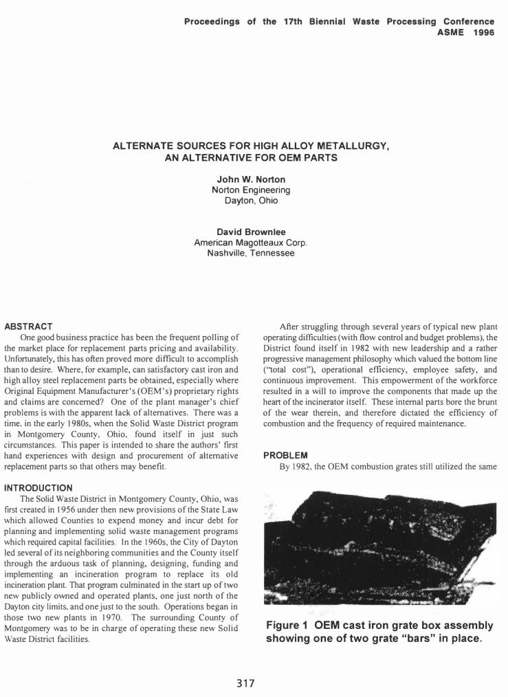
By 1982, the OEM combustion grates still utilized the same
Figure 1 OEM cast iron grate box assembly showing one of two grate "bars" in place.
cast iron design that had been originally purchased by the Montgomery County Solid Waste District in 1967; only now the design was at least 15 years old with no apparent improvement and several apparent weaknesses. The OEM grate assembly consisted of a "box" approximately 18" long by II" wide (45 cm by 25 cm). See Fig. I. Typical American trash content would get wedged into the slots between the bars and jam them tightly closed. These were supposed to be underfire air passages. Unfortunately. however. not only did they not ,function in that capacity. but the jamming would result in additional hangups of trash on the surface of the grate. That hung up trash would reciprocate back and forth. up and down. instead of moving forward through the combustion area as intended. Discussions with the original vendor led nowhere; sympathetic hearings did not result in requested improvements. In 1983. this district's engineers set about developing alternative replacement parts.
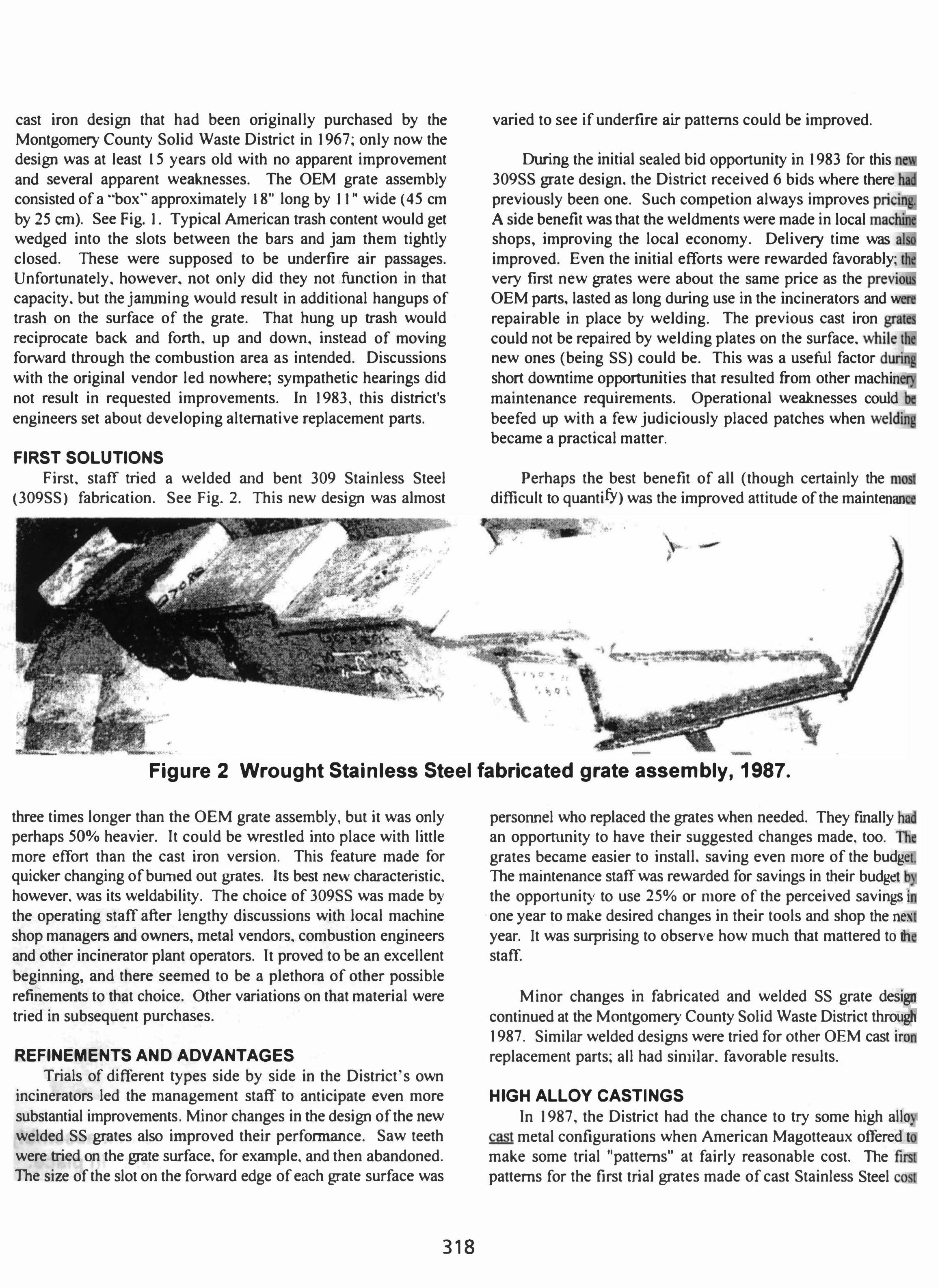
FIRST SOLUTIONS First. staff tried a welded and bent 309 Stainless Steel
(309SS) fabrication. See Fig. 2. This new design was almost
•
"'-. . .. . .
• •
I' . • " / • •• o' j'
,
varied to see if underftre air patterns could be improved.
During the initial sealed bid opportunity in 1983 for this 309SS grate design. the District received 6 bids where there .--, previously been one. Such competion always improves A side benefit was that the weldments were made in local shops. improving the local economy. Delivery time was improved. Even the initial efforts were rewarded favorably; very first new grates were about the same price as the .".,.,..
OEM parts. lasted as long during use in the incinerators and w .
repairable in place by welding. The previous cast iron grali
could not be repaired by welding plates on the surface. while""" new ones (being SS) could be. This was a useful factor short downtime opportunities that resulted from other machin maintenance requirements. Operational weaknesses could beefed up with a few judiciously placed patches when became a practical matter.
Perhaps the best benefit of all (though certainly the difficult to quantifY) was the improved attitude of the maintenan
•
•• •
� •
Figure 2 Wrought Stainless Steel fabricated grate assembly, 1987.
three times longer than the OEM grate assembly. but it was only perhaps 50% heavier. It could be wrestled into place with little more effort than the cast iron version. This feature made for quicker changing of bumed out grates. Its best new characteristic. however. was its weldabiIity. The choice of 309SS was made by the operating staff after lengthy discussions with local machine shop managers and owners, metal vendors. combustion engineers and other incinerator plant operators. It proved to be an excellent beginning, and there seemed to be a plethora of other possible refinements to that choice. Other variations on that material were tried in subsequent purchases.
REFINEMENTS AND ADVANTAGES Trials of different types side by side in the District's own
incinerators led the management staff to anticipate even more substantial improvements. Minor changes in the design of the new welded SS grates also improved their performance. Saw teeth were tried on the grate surface. for example. and then abandoned. The size of the slot on the fOl'\vard edge of each grate surface was
318
personnel who replaced the grates when needed. They finally hi an opportunity to have their suggested changes made. too. Tit
grates became easier to install. saving even more of the budge The maintenance staff was rewarded for savings in their budget the opportunity to use 25% or more of the perceived savings) one year to make desired changes in their tools and shop the nex
year. It was surprising to observe how much that mattered to th staff.
Minor changes in fabricated and welded SS grate desigl'f continued at the Montgomery County Solid Waste District througtj 1987. Similar welded designs were tried for other OEM cast ira replacement parts; all had sinli1ar. favorable results.
HIGH ALLOY CASTINGS In 1987, the District had the chance to try some high a110.
cast metal configurations when American Magotteaux offered t make some trial "patterns" at fairly reasonable cost. The patterns for the first trial grates made of cast Stainless Steel

$2520 in 1988. Their fIrst trials involved a substitute grate assembly with replaceable grate covers. See Figures 3 and 4. The tops of the grates directly faced the fire and sliding solid waste causing that area to "bum out" first. When American Magotteaux got involved with the design they came up with a two part grate assembly with replacable grate covers for grate side walls that would outlast the covers by 2 to 4 times. The cast covers cost roughly 1/3 of the price of the complete grate assembly.
Figure 3 Cast SS Grate Assembly with Replaceable Covers.
Figure 3 Cast Grate Assembly without Covers.
The overall shape of this new assembly was roughly similar and about ) 12 as long as the latest version of the 309 SS configuration.
COSTS The cost of the first cast SS grate assemblies was $418 each. I
Even though hvo were required to replace each of the wrought 309 SS assemblies, this price (x 2 = $836) compared favorably with the approximate cost of $1 ) 00 for the latest wrought 309SS assemblies. Complete grate assemblies cost $465 in ) 990. The reason for the change in overalllenf,rth of the assembly had to do with the difficulty of casting long thin wall sections. The new cast SS grate covers could be replaced 2 to 4 times before the grate sidewalls needed to be replaced. See Figure 5, showing typical combustion wear on cast SS f,rrate covers.
Amortized over one year"s worth of replacement grate purchases. a new pattern design only represented perhaps 10% of the part price. It wasn't long before attempts were made to cast
1 . . Montgomery County. OhIO, Bid Number 90-87.
319
virtually all of the metal wearing parts in the incinerator. Most of the changes produced good results. When the staff that uses the parts (installs and removes them) is closely involved with such design changes, it is not unusual to produce favorable results.
Magotteaux was familiar with high alloy metallurgy and suggested that HH-2 be tried for the first casting trials on the grate covers. HH-2 is a 25Cr, 12Ni Stainless Steel with .35 to .40 carbon content. As a general rule. a cast SS grade with a higher carbon content will exhibit more high temperature strength, be more abrasion resistant. and more resistant to wear than the wrought (fabricated and welded) equivalent. On the downside, the cast SS will have a lower ductility and thus be more prone to cracking.
There are thickness, thinness, and other such restraints involved with the design of cast components also, but with the establishment of a cooperative working relationship with a foundry design staff, most of those concerns can be accommodated. In some instances, the best solution ended up being a combination of the cast parts and wrought parts. The drying grates. for example have proved to be most effective when cast covers are mounted on "''fought SS sidewalls.
Figure 5 Burned Out Grate Covers
The second type of major replacement part that the stall' engineers decided to try designing was the Kiln Outlet Plates, which hold the kiln refractory in place. They were a fairly simple flat plate, but as OEM replacement parts. the price for each was substantial, about $600 each in 1985. Staff decided at first to try them as wrought 309SS plate. Fig. 6 shows the type of wear experienced in the combustion process on the wrought 309SS Kiln Outlet Plates. Kiln Inlet Plates. which hold the kiln refractory in place at the other end , were also reconfigured as wrought 309SS plate. Both were eventually reconfigured as high alloy cast plates

in order to extend their operational life. See Figure 7.
MINOR CHANGES, BIG ADVANTAGES Rather minor variations in the part design can sometimes
calise significant changes in the part life. When bolt protection flanges were added to the mold pattern and thus to the part, the
•
,
, ',V
Figure 6 Wrought 30955 Kiln Outlet Plate showing wear.
,
,
. ... ,.
Figure 8 High Alloy Cast Kiln End Plates with Nut Protection Flanges
life of the part essentially doubled. Bolt heads had been off during incineration by the abrasive action of hot ash. Kiln end plates would actually fall off long before they substantially worn. Bolt protection flanges were added to high alloy cast plates as shown in Figure 8. With bolt flanges in place, the part was retained in use W1til it burned and needed to be replaced for that reason, Similar
modifications were made in the assemblies to cure failure problems seemed premature. Changes were in the wear bars on each side of the box as well as to the shape of the
covers to promote underfire air where additional cooling seemed to
promise of longer life. There was substitute for trial and error on full operating systems to resolve technical speCUlation.
Figure 7 High Alloy Cast Kiln Outlet End Plates
The third part to W1dergo this pattern of redesign from OEM cast iron
to 309SS to high alloy castings was the ash Diversion Gate. This incinerator
component is the movable slide which directs hot ash into the backup ash quench tank when the primary ash conveyor is down for repairs or maintenance, When in the diverting mode. the gate must present a smooth
slide surface to the hot ash. The hope is that the ash will slip along the surface
and slide directly into the backup ash
320

quench conveyor. Figure 9 shows the wrought 309SS gate components installed with refractory cast in place to help protect the "back" of the diversion gate from high temperature corrosion when the gate is in its "normal standby" position. The gate is shown in the standby position.
Figure 9 Wrought 309SS Diversion Gate in place.
Figure 10 shows a cast version ready to be assembled and installed. With these cast sections. diversion gate life increased by
Figure 10 Cast SS Diversion Gate sections ready for assembly and installation.
approximately 75% and total replacement costs for these systems dropped by about 50%. The material finally chosen for these gate sections and the Kiln Inlet and Outlet Plates was a low Carbon. 19Cr. 9Ni with additives to ward off thennal fatigue.
Other replacement components which were redesigned and configured finally as high alloy SS castings included the
321
following:
• "Bull Nose Plates", the assembly which provided for the transition between the reciprocating grates and the refractory lined rotary kiln. were originally a two part
•
•
Figure 1 1 High Alloy Cast "Bull Nose Plate" Shelf pieces.
cast iron support assembly (each over 1600 lbs. (750 KG» protected by several hefty cast iron wear plates (approximately 300 Ibs. (135 KG) each). This assembly was reconfigured as a single 309SS Y2 in. to 5/8 in. plate (13 mm to 16 mm) with a wrought 309SS top shelf to protect refractory and a wrought 309SS bottom shelf to support the refractory. Eventually the top and bottom shelves were modified to be made of cast SS, but the plate remains 309SS. Figure II shows the cast SS Shelf pieces which hold the refractory.
Grate End Guards, the parts that keep trash from falling into and clogging the reciprocation void at the upper end of the grate slope, w e r e reconfigured as wrought 3 0 9 S S, eventually to be made of cast SS as shown in Figures 12.
Virtually all other cast iron
Figure 12 Grate End Guard.
parts were similarly modified. A few were replaced with
silicon carbide refractory, but that is a different topic.
SUMMARY AND CONCLUSIONS The Solid Waste District which serves Dayton, Ohio,
with two operating incineration plants found that there were
readily available alternatives to original OEM replacement
wear parts. Staff found that several foundries in the United
States are willing to work with staff engineers and
maintenance workers to redesign replacement parts, a
substitute for OEM parts. The practice proved to be most
valuable in several ways: competition improved pricing,
redesign improved operational life, and staff workers felt
empowered to make their plant systems wo'rk better. This
operating district even increased the opportunity for recycling by working out an arrangement with its high alloy cast part
supplier to take back the worn out parts and use them in
casting the new parts.
As a result of this operating district's experience, it seems reasonable to believe that any operational staff could
develop replacement part alternatives to the OEM parts
presently available to them. If an operating staff strongly
desires some changes in its replacement parts, it should give
serious thought to trying some parts redesign. All it takes is
a will and the willingness to discuss the possibilities with key maintenance staff (empowerment) and the available machine
shops and foundries that are likely to be interested in the
business opportunities such efforts will bring.
322