PROCEEDINGS OF SPIE - library.ssec.wisc.edulibrary.ssec.wisc.edu/research_Resources/...The...
15
PROCEEDINGS OF SPIE SPIEDigitalLibrary.org/conference-proceedings-of-spie The University of Wisconsin Space Science and Engineering Center Absolute Radiance Interferometer (ARI): instrument overview and radiometric performance Joe K. Taylor, Henry E. Revercomb, Henry Buijs, Frederic J. Grandmont, P. Jonathan Gero, et al. Joe K. Taylor, Henry E. Revercomb, Henry Buijs, Frederic J. Grandmont, P. Jonathan Gero, Fred A. Best, David C. Tobin, Robert O. Knuteson, "The University of Wisconsin Space Science and Engineering Center Absolute Radiance Interferometer (ARI): instrument overview and radiometric performance," Proc. SPIE 8527, Multispectral, Hyperspectral, and Ultraspectral Remote Sensing Technology, Techniques and Applications IV, 85270P (9 November 2012); doi: 10.1117/12.977533 Event: SPIE Asia-Pacific Remote Sensing, 2012, Kyoto, Japan Downloaded From: https://www.spiedigitallibrary.org/conference-proceedings-of-spie on 11/20/2018 Terms of Use: https://www.spiedigitallibrary.org/terms-of-use
Transcript of PROCEEDINGS OF SPIE - library.ssec.wisc.edulibrary.ssec.wisc.edu/research_Resources/...The...
PROCEEDINGS OF SPIE
SPIEDigitalLibrary.org/conference-proceedings-of-spie
The University of Wisconsin SpaceScience and Engineering CenterAbsolute Radiance Interferometer(ARI): instrument overview andradiometric performance
Joe K. Taylor, Henry E. Revercomb, Henry Buijs, FredericJ. Grandmont, P. Jonathan Gero, et al.
Joe K. Taylor, Henry E. Revercomb, Henry Buijs, Frederic J. Grandmont, P.Jonathan Gero, Fred A. Best, David C. Tobin, Robert O. Knuteson, "TheUniversity of Wisconsin Space Science and Engineering Center AbsoluteRadiance Interferometer (ARI): instrument overview and radiometricperformance," Proc. SPIE 8527, Multispectral, Hyperspectral, andUltraspectral Remote Sensing Technology, Techniques and Applications IV,85270P (9 November 2012); doi: 10.1117/12.977533
Event: SPIE Asia-Pacific Remote Sensing, 2012, Kyoto, Japan
Downloaded From: https://www.spiedigitallibrary.org/conference-proceedings-of-spie on 11/20/2018 Terms of Use: https://www.spiedigitallibrary.org/terms-of-use

The University of Wisconsin Space Science and Engineering Center Absolute Radiance Interferometer (ARI): Instrument Overview and
Radiometric Performance Joe K. Taylora,c, Henry E. Revercomba, Henry Buijsb, Frederic J Grandmontb, P. Jonathan Geroa,
Fred A. Besta, David C. Tobina, Robert O. Knutesona a Space Science and Engineering Center, University of Wisconsin-Madison, 1225 West Dayton
Street, Madison, WI, USA, 53706 b ABB-Bomem Inc. 585 Charest E, Suite 300, Quebec, QC, G1K 9H4, Canada
c Université Laval, Québec, G1K 7P4, Canada.
ABSTRACT
Spectrally resolved infrared (IR) and far infrared (FIR) radiances measured from orbit with extremely high absolute accuracy (< 0.1 K, k = 3, brightness temperature at scene temperature) constitute a critical observation for future climate benchmark missions.
The challenge in the IR/FIR Fourier Transform Spectrometer (FTS) sensor development for a climate benchmark measurement mission is to achieve the required ultra-high accuracy with a design that can be flight qualified, has long design life, and is reasonably small, simple, and affordable. In this area, our approach is to make use of components with strong spaceflight heritage (direct analogs with high TRL) combined into a functional package for detailed performance testing. The required simplicity is achievable due to the large differences in the sampling and noise requirements for the benchmark climate measurement from those of the typical remote sensing infrared sounders for weather research or operations.
A summary of the instrument design and development, and the radiometric performance of the Absolute Radiance Interferometer (ARI) at the University of Wisconsin Space Science and Engineering Center (UW-SSEC) will be presented.
Keywords: FTS, Fourier Transform Spectrometer, Climate Benchmark Measurement, IR, FIR
1. INTRODUCTION The objective of this effort is to develop and demonstrate the technologies needed to measure spectrally resolved infrared (IR) and far infrared (FIR) radiances from orbit with the ultra high accuracy (< 0.1 K, k = 3, brightness temperature at scene temperature) required for a climate benchmark mission.
1.1 Climate Benchmark Measurements from Space
The climate benchmark measurement paradigm and accuracy requirement for the IR and FIR is defined in the ASIC3 (Achieving Satellite Instrument Calibration For Climate Change) report [1], and the US National Research Council Decadal Survey recommended Climate Absolute Radiance and Refractivity Observatory (CLARREO) mission [2]. The NRC Survey states the principles on which new climate missions should be based: “Design of climate observing and monitoring systems from space must ensure the establishment of global, long-term climate records, which are of high accuracy, tested for systematic errors on-orbit, and tied to irrefutable standards.” “For societal objectives that require long-term climate records, the accuracy of core benchmark observations must be verified against absolute standards on-orbit by fundamentally independent methods, such that the accuracy of the record archived today can be verified by future generations. Societal objectives also require a long-term record not susceptible to compromise by interruptions.”
*[email protected]; phone 1 608 263 4494; fax 1 608 262 5974; www.ssec.wisc.edu
Multispectral, Hyperspectral, and Ultraspectral Remote Sensing Technology, Techniques and Applications IV, edited by Allen M. Larar, Hyo-Sang Chung, Makoto Suzuki, Jian-yu Wang, Proc. of SPIE Vol. 8527, 85270P
© 2012 SPIE · CCC code: 0277-786/12/$18 · doi: 10.1117/12.977533
Proc. of SPIE Vol. 8527 85270P-1Downloaded From: https://www.spiedigitallibrary.org/conference-proceedings-of-spie on 11/20/2018Terms of Use: https://www.spiedigitallibrary.org/terms-of-use

Absolute Radiance Interferometer (ARI)
Calibration Reference: Ambient Blackbody(ABB)
On -orbit Spectral Response Module (OSRM)
JCalibration Reference Hot Blackbody (HBB)
On -orbit Cavity Emissivity Module (OCEM) On -orbit Absolute Radiance Standard (OARS)
CLARREO will measure spectrally resolved radiance from the Earth and atmospheric bending of GPS signals related to atmospheric structure (refractivity) as benchmark measurements of long-term climate change trends. A simple instrument design is key to achieving the ultra-high absolute accuracy requirements associated with infrared spectral radiances. The required simplicity is achievable due to the large differences in the sampling and noise requirements for the benchmark climate measurement from those of the typical remote sensing infrared sounders for weather research or operational weather prediction. Studies show that for the climate benchmark measurement paradigm, which emphasizes information content rather than calorimetry, the key climate information can be obtained with nadir only viewing, relatively large footprints (<100 km), and modest requirements on noise performance [3, 4]. The key is to demonstrate extremely low combined measurement and sampling biases for the climate products, which consist of annual averages of nadir radiance spectra averaged over large latitude-longitude regions (of the order of 15º x 30º) and seasonal averages on even larger spatial scales (of the order of 50º x 50º latitude-longitude regions). The striking differences from weather-driven requirements lead to very important reductions in sensor size, mass, and power that enable the novel climate accuracy requirements to be achieved with a relatively low demand on spacecraft resources and cost.
For the infrared radiance spectra, it has been determined that a measurement accuracy, expressed as an equivalent brightness temperature error, of 0.1 K (k = 3) confirmed on orbit is required [1, 5].
1.2 A New Class of Advanced Accuracy Satellite Instrumentation (AASI)
The University of Wisconsin-Madison Space Science and Engineering Center (UW-SSEC) and Harvard University (HU) submitted a successful joint proposal entitled “A New Class of Advanced Accuracy Satellite Instrumentation (AASI) for the CLARREO Mission” to the NASA Instrument Incubator Program (IIP). The UW-SSEC / HU team has a long history with the scientific and measurement concepts that have formed the foundation for climate benchmark measurements [1,3-10].
Figure 1: Technology developments under NASA IIP funded proposal “A New Class of Advanced Accuracy Satellite
Instrumentation (AASI) for the CLARREO Mission”.
Proc. of SPIE Vol. 8527 85270P-2Downloaded From: https://www.spiedigitallibrary.org/conference-proceedings-of-spie on 11/20/2018Terms of Use: https://www.spiedigitallibrary.org/terms-of-use

rI SeconI I DTGS Detector I Port R
r°'1
d Inputaference GICS
IR Detectors andDewar
Dashed line indicates OTV enclosure envelope.
The objective of this effort is to develop and demonstrate the technologies needed to measure IR spectrally resolved radiances with ultra high accuracy for climate benchmark measurements from space. The effort combines the development of fundamentally new devices including (1) the On-orbit Absolute Radiance Standard (OARS), a high emissivity blackbody source that uses multiple miniature phase-change cells to provide a revolutionary in situ standard with absolute temperature accuracy proven over a wide range of temperatures. The OARS is a source that will be used to maintain SI traceability of the radiance spectra measured by the calibrated interferometer sensor [11-14]; (2) On-orbit Cavity Emissivity Modules (OCEMs), providing a source (quantum cascade laser (QCL) or “Heated Halo”) to measure any change in the cavity emissivity of the OARS and calibration reference sources [15-19]; (3) an On-orbit Spectral Response Module (OSRM), a source for spectral response measurements using a nearly monochromatic QCL source configured to uniformly fill the sensor field-of-view, and (4) the Absolute Radiance Interferometer (ARI) for measuring spectrally resolved radiances with a spectral coverage of 200 – 2500 cm-1 at 0.5 cm-1 spectral resolution and a radiometric accuracy of < 0.1 K, k = 3, brightness temperature at scene temperature [20-23].
2. THE ABSOLUTE RADIANCE INTERFEROMETER (ARI) The UW-SSEC ARI is comprised of
• A scene selection mirror assembly;
• Fore optics designed specifically for high radiometric accuracy;
• A 4-port cube corner, rocking arm interferometer with a diode laser based metrology system;
• Two aft optics assemblies, 1 at each output port of the interferometer;
• A 77 K multiple semi-conductor detector (400 – 2500 cm-1) and dewar assembly;
• A very small mechanical cooler for the semi-conductor detector and dewar subassembly;
• A DTGS pyroelectric detector (200 – 1800 cm-1) assembly.
Each are chosen for their strong spaceflight heritage such that detailed performance testing can be conducted on a system with a clear path to space. For compatibility with an IIP budget and schedule, the electronics are not flight designs.
(a) (b)
Figure 2: Completed ARI sensor prototype (a) On-orbit Test and Verification (OTV) module (b) ARI.
Proc. of SPIE Vol. 8527 85270P-3Downloaded From: https://www.spiedigitallibrary.org/conference-proceedings-of-spie on 11/20/2018Terms of Use: https://www.spiedigitallibrary.org/terms-of-use

2.1 Instrument design and key trade-studies
Several trade-studies were conducted during the design phase. Key studies and considerations included, but were not limited to, interferometer configuration, Technological Readiness Level (TRL) and flight heritage, beamsplitter material and configuration, beam divergence and throughput, optical stop locations, spectral ranges for detector bands, and signal chain nonlinearity and sensitivity.
2.1.1 Interferometer Configuration
The design criteria included spectral resolution and range; sensitivity and throughput requirements; size, weight, and power considerations; and vibration and temperature concerns.
Flat mirrors compensate for two degrees of freedom in shift but are susceptible to tilt misalignment unless dynamic alignment is provided. Cat’s eye and cube corner mirrors protect against two degrees of freedom in tilts but not shear. Cube corners can be compensated for shear if an additional flat return mirror is added at the exit of the cube corner such that the beam retraces its steps back through the cube corner. Given the 0.1 K (k = 3) calibration accuracy requirement, current cube corner manufacturing and assembly techniques, the reduced sensitivity to shear compared to tilt, and the required maximum optical path difference (MOPD) for the ARI system, cube-corners were selected. The classical arrangement, with no additional flat return mirror in one arm, is appropriate for the required spectral resolution and coverage requirements. Two port and four port configurations were considered. Since the four-port configuration is immune to the double pass problem, a primary concern for the broadband coverage requirements, a four-port design was chosen.
2.1.2 Technology Readiness Level (TRL) and Flight Heritage
The history of FTS in space has been remarkably successful, and has demonstrated that FTS instruments can be designed sufficiently rugged to survive launch. FTS have been packaged in small payloads for Small-Sat and rover applications, and several systems have survived and operated in space for significant periods of time.
ABB-Bomem currently has 3 spaceborne FTS (ACE, GOSAT, CrIS) successfully launched and operating in space. These flight designs leverage over 35 years of research and commercial FTS design and manufacturing experience. ABB’s newest flight design, the Generic Flight Interferometer (GFI), incorporates their FTS flight heritage from recent flight programs. Risk mitigation demonstration prototypes have been manufactured and tested (and continue to be tested) to establish Technology Readiness Level (TRL) and performance capability.
Given TRL and flight heritage requirements, cost considerations, and the significant UW SSEC experience with implementation, test and analysis, and high accuracy calibration of ABB-Bomem interferometers (S-HIS, AERI, NAST-I, CrIS), it was decided that the ARI interferometer core would be based on an existing ABB-Bomem flight design. For compatibility with project funding, commercial electronics are used.
The GFI and TANSO-FTS engineering demonstration units were compared in the context of the requirements for the ARI interferometer. Both interferometer cores meet or exceed defined requirements, minimize non-recurring engineering costs by leveraging existing ABB designs, utilize ABB COTS electronics and software, and are designs with extensive space flight heritage and flight qualification
Etendue, metrology, testing and qualification, maximum optical path difference (MOPD), mass, power, volume, scan speed stability, shear, modulation efficiency, transmittance, procurement costs and schedule were considered and the GFI based design was chosen as a baseline (with ABB commercial off-the-shelf (COTS) electronics for the IIP demonstration).
To meet the climate benchmark measurement requirements, minor modifications to the GFI were necessary. The resulting interferometer core is the Generic Interferometer for Climate Studies (GICS).
2.1.3 Beamsplitter
The GFI utilizes a Zinc Selenide (ZnSe) beamsplitter, which is the best candidate material for coverage of the 700 – 3000 cm-1 spectral range, but does not provide coverage in the FIR region required for the climate benchmark measurement. Several beamsplitter materials and configurations were considered. Materials included Cesium Iodide, Silicon, and CVD diamond.
Proc. of SPIE Vol. 8527 85270P-4Downloaded From: https://www.spiedigitallibrary.org/conference-proceedings-of-spie on 11/20/2018Terms of Use: https://www.spiedigitallibrary.org/terms-of-use

Pellicle and wire grids were also considered as beamsplitter candidates. However, they are extremely delicate, vibration sensitive, and provide limited shortwave IR coverage. Due to these concerns it was decided that pellicle and wire grids were not a feasible option.
Silicon and CVD diamond provide spectral coverage well beyond the longwave requirement (200 cm-1) for the climate benchmark measurement. Silicon has outstanding efficiency well below 100 cm-1, but exhibits strong phonon absorption at 618 cm-1. Phonon absorption is dependent on material thickness and can be minimized by making the silicon wafer very thin. In CVD diamond, intrinsic absorption limits its efficiency at shorter wavelengths. A single plate uncoated and uncompensated beamsplitter configuration is the best option for both materials. The primary concern with this configuration is the associated extensive optical channeling. Channeling amplitude may be controlled through increasing beam divergence and optical element thickness, and the channeling frequency is also a function of element thickness. However, beam divergence and beamsplitter thickness are also subject to other design constraints. The stability of the fringing depends on temperature stability, and the material’s refractive index temperature dependence and thermal expansion coefficient. Accordingly, additional constraints are placed on thermal stability of the beamsplitter temperature during the calibration cycle if the effect is to be made negligible after calibration. Finally, Silicon and CVD diamond beamsplitters do not have significant heritage and would require additional testing and technology development that is not compatible with the laboratory demonstration schedule and budget.
Multiple Cesium Iodide beamsplitter configurations were considered and a single substrate, self-compensated configuration was chosen. This ABB-Bomem proprietary design requires retro-reflection and translation of the optical beam at the interferometer mirrors, and is thus only possible in a cube-corner (or equivalent) interferometer configuration. Parallelism of the substrate faces is crucial to this design and wedging of the beamsplitter substrate causes misalignment and cannot be used to eliminate channeling. This configuration provides precise compensation of OPD dispersion and a highly symmetric interferogram.
2.1.4 Beam Divergence and Etendue
Beamsplitter channeling, etendue, interferometer self-apodization, and non-uniform scene effect on instrument line shape (ILS) all depend on the beam divergence in the interferometer. Increased beam divergence minimizes channeling effects, but increases self-apodization, and results in larger corrections for ILS normalization and larger effects for non-uniform scenes. Etendue is a function of aperture size and location, and beam divergence. Based on these considerations, a beam divergence (in the interferometer) of b = 25.8 mrad (half angle) was chosen. To maximize etendue the pupil is placed at the cube-corner. To maximize throughput while minimizing interferometer volume and accounting for cube corner manufacturing limitations, a pupil diameter of 1” was chosen.
2.1.5 Optical Design
The fore-optics and FIR aft-optics consist of all reflective elements. The IR aft-optics assembly consists of a two reflective elements, combined with in-dewar 77 K refractive optics. Each reflective element is diamond point turned aluminum, plated with uncoated Epner Gold. The use of uncoated gold minimizes polarization issues while maintaining high transmission. The optical design goals included:
• Optimization of interferometer throughput;
• Maximal stray light control;
• Minimization of instrument mass and volume;
• Optimization of the heated halo geometrical fill factor;
• Compatibility with a 1” aperture Blackbody;
• Capability for tuning of polarization sensitivity “null” locations with respect to the position of the calibration reference bodies, OARS, and scene views.
These goals, combined with other instrument requirements, resulted in a fore-optics design that provides an afocal magnification of 2.3, accommodates well-defined field and aperture stops, and relays the aperture stop to pupils at the interferometer cube-corner and the halo entrance aperture.
Due to schedule and budget considerations, the FIR aft-optics module for the IIP demonstration is based on the current generation ABB AERI aft-optics system modified to include a field and aperture stop such that the sensor may be
Proc. of SPIE Vol. 8527 85270P-5Downloaded From: https://www.spiedigitallibrary.org/conference-proceedings-of-spie on 11/20/2018Terms of Use: https://www.spiedigitallibrary.org/terms-of-use
PolarizationCharacterizationView°
operated without the fore-optics in the system. The aft-optics stop sizes are adjustable, such that they can be changed so that they are not the limiting stops when the fore-optics are installed in the system, and to provide flexibility during testing.
2.2 Operational Concept
On-orbit, the sensor will be radiometrically calibrated using views of a dedicated onboard full-aperture blackbody reference and space. For laboratory testing, the space reference is replaced by a second dedicated blackbody reference. The sensor has been designed to minimize potential biases related to non-linear response and polarization effects. Tests to characterize detector linearity have been conducted. Sensor polarization sensitivity has been modeled and tests to confirm this model are planned.
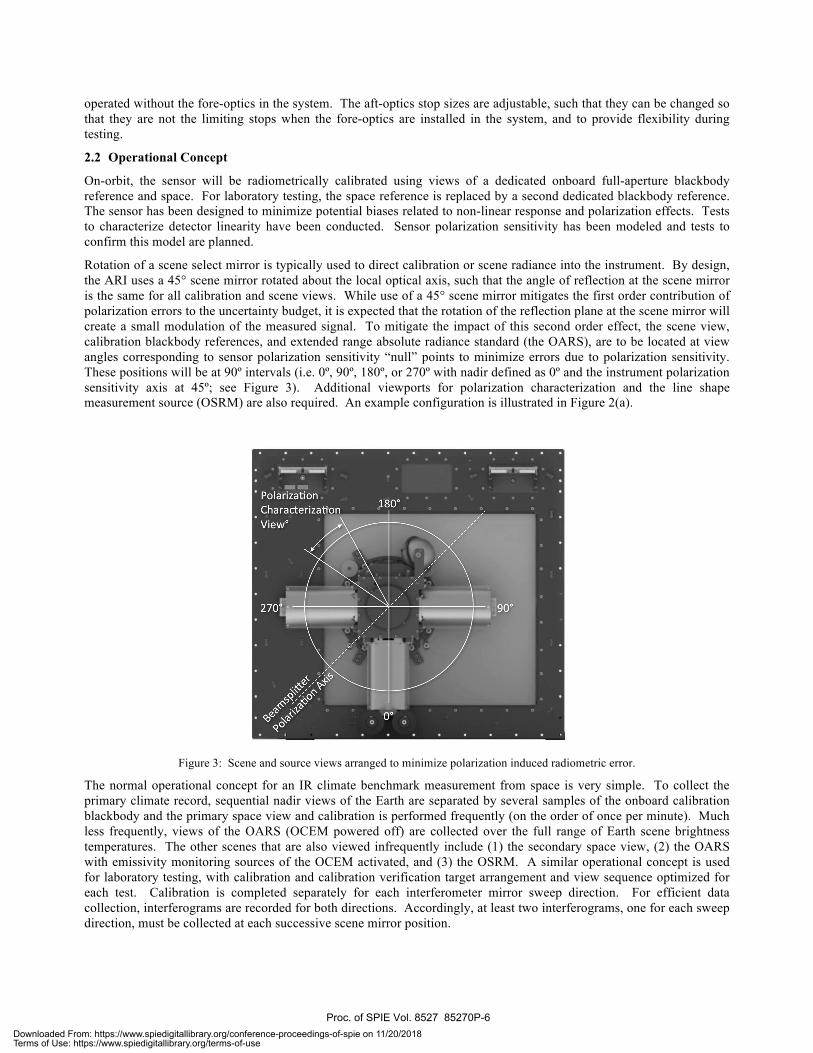
Rotation of a scene select mirror is typically used to direct calibration or scene radiance into the instrument. By design, the ARI uses a 45° scene mirror rotated about the local optical axis, such that the angle of reflection at the scene mirror is the same for all calibration and scene views. While use of a 45° scene mirror mitigates the first order contribution of polarization errors to the uncertainty budget, it is expected that the rotation of the reflection plane at the scene mirror will create a small modulation of the measured signal. To mitigate the impact of this second order effect, the scene view, calibration blackbody references, and extended range absolute radiance standard (the OARS), are to be located at view angles corresponding to sensor polarization sensitivity “null” points to minimize errors due to polarization sensitivity. These positions will be at 90º intervals (i.e. 0º, 90º, 180º, or 270º with nadir defined as 0º and the instrument polarization sensitivity axis at 45º; see Figure 3). Additional viewports for polarization characterization and the line shape measurement source (OSRM) are also required. An example configuration is illustrated in Figure 2(a).
Figure 3: Scene and source views arranged to minimize polarization induced radiometric error.
The normal operational concept for an IR climate benchmark measurement from space is very simple. To collect the primary climate record, sequential nadir views of the Earth are separated by several samples of the onboard calibration blackbody and the primary space view and calibration is performed frequently (on the order of once per minute). Much less frequently, views of the OARS (OCEM powered off) are collected over the full range of Earth scene brightness temperatures. The other scenes that are also viewed infrequently include (1) the secondary space view, (2) the OARS with emissivity monitoring sources of the OCEM activated, and (3) the OSRM. A similar operational concept is used for laboratory testing, with calibration and calibration verification target arrangement and view sequence optimized for each test. Calibration is completed separately for each interferometer mirror sweep direction. For efficient data collection, interferograms are recorded for both directions. Accordingly, at least two interferograms, one for each sweep direction, must be collected at each successive scene mirror position.
Proc. of SPIE Vol. 8527 85270P-6Downloaded From: https://www.spiedigitallibrary.org/conference-proceedings-of-spie on 11/20/2018Terms of Use: https://www.spiedigitallibrary.org/terms-of-use

Determination of the number of interferograms collected at each scene mirror position is based on instrument thermal stability, with a goal of minimizing calibration errors associated with nonlinear changes in instrument emission between calibration reference views while maximizing time spent viewing the target scene and calibration bodies.
The ARI reference blackbodies are based on the UW SSEC Geostationary Imaging FTS (GIFTS) blackbody design [24, 25]. Minor design modifications were made for the OARS, along with the addition of multiple miniature phase-change cells. The OARS uses transient temperature melt signatures from three (or more) different phase change materials to provide absolute calibration for the blackbody thermistor sensors covering a wide, continuous range of temperatures [11-14]. The system uses very small masses of phase change material (<1 g), making it well suited for spaceflight application.
3. RADIOMETRIC PERFORMANCE 3.1 Radiometric Calibration and Uncertainty
The complex calibration method is used for this project. Complex calibration is an efficient method developed to correct the amplitude and phase of the measured spectrum [26]. This approach requires two distinct calibration references, or a single reference operated and observed at two distinct temperatures. The basic calibration expression for the complex calibration method is:
LS ! k( ) = LH ! k( )" LC ! k( )( )Re C S ! k( )"C C ! k( )
C H ! k( )"C C ! k( )#$%
&'(+ LC ! k( ) . (1)
In Eq. (1), LS (! k ) is the calibrated radiance; C S (! k ) , C C (! k ) and C H (! k ) are the complex measured spectra for the
scene, cold calibration reference, and hot calibration reference views respectively; and LC (! k ) and LH (! k ) are the calculated radiances for the respective cold and hot calibration reference views. The calculated radiance from a non-ideal blackbody cavity is the sum of the emitted and reflected radiance from the cavity:
L ! k( ) = e ! k( )B(! k ,T ) + 1" e ! k( )( )B(! k ,TR ) , (2)
where e(! k ) is the effective emissivity of the blackbody, B(! k ,T ) is the Planck radiance for an ideal blackbody of temperature T, and B(! k ,TR ) is the Planck radiance of the background, of mean temperature TR , that is reflected from the cavity.
If the reference spectra are collected with sufficient frequency such that the change in instrument emission between reference views is small and the measured spectra and calculated radiances for the reference views may be accurately interpolated to the time of the scene measurement, then any complex offset or phase associated with the warm instrument emission is cancelled in the ratio of complex difference spectra contained in Eq. (1).
The error associated with the calibrated radiance may be estimated by calculating the combined uncertainty for L(! k ) [27]. There is no expected first order correlation for the input quantities in Eq. (1), and it is valid to use the root sum squares (RSS) method for estimation of the combined uncertainty u 2 (LS ) in calibrated radiance L(! k ) :
u 2 LS( ) = !LS
!TH
"#$
%&'2
u 2 TH( ) + !LS
!eH
"#$
%&'2
u 2 eH( ) + !LS
!TR ,H
"#$
%&'
2
u 2 TR ,H( )
+!LS
!TC
"#$
%&'2
u 2 TC( ) + !LS
!eC
"#$
%&'2
u 2 eC( ) + !LS
!TR ,C
"#$
%&'
2
u 2 TR ,C( )
+!LS
!X"#
%&
2
u 2 X( ) ,
(3)
Proc. of SPIE Vol. 8527 85270P-7Downloaded From: https://www.spiedigitallibrary.org/conference-proceedings-of-spie on 11/20/2018Terms of Use: https://www.spiedigitallibrary.org/terms-of-use

where TH and TC are the temperature of the hot and cold calibration reference targets, with respective uncertainties
u(TH ) and u(TC ) ; TR ,H , TR ,C are the mean temperature of the background radiance that is reflected from the hot and
cold reference targets, with respective uncertainties u(TR ,H ) and u(TR ,C ) ; eH and eC are the effective emissivities of the
hot and cold blackbodies, with uncertainties u(eH ) and u(eC ) ; and X represents the measured spectra term:
X = Re
C S ! k( )"C C ! k( )C H ! k( )"C C ! k( )
#$%
&'(. (4)
Assessment of the combined uncertainty u(X ) of the measured spectra term is completed via models and perturbation analysis. For the analysis, it has been assumed that the potentially dominant source of uncertainty associated with the measured spectra will be signal chain nonlinearity. This assumption is based on past experience with design, analysis, and testing of the AERI [28-30], S-HIS, and GIFTS instruments, and testing and analysis of the CrIS [31,32] instrument. Polarization sensitivity induced error can also be a significant contributor to measurement uncertainty, but is expected to be a negligible contributor given the instrument design. Tests will be conducted to confirm this expectation.
The radiance bias !L(" ) may be expressed as the difference between the true radiance L(! ) and the observed calibrated radiance LS (! k ) :
!L "( ) = L "( ) # LS " k( ) . (5)
The uncertainty in the verification of the calibrated radiance includes a contribution from the uncertainty in the determination of the true radiance in addition to the uncertainty in the measured radiance:
u 2 !L( ) = " !L( )
"L#$
%&
2
u 2 L( ) + " !L( )"LS
#$'
%&(2
u 2 LS( )
= u 2 L( ) + u 2 LS( ) . (6)
The uncertainty associated with the On-orbit Absolute Radiance Standard (OARS) is given by:
u 2 LOARS( ) =!LOARS
!TOARS
"#$
%&'2
u 2 TOARS( ) + !LOARS
!eOARS
"#$
%&'2
u 2 eOARS( ) + !LOARS
!TR ,OARS
"#$
%&'
2
u 2 TR ,OARS( ) . (7)
In Eq. (7), TOARS is the temperature of the OARS with uncertainty u(TOARS ) , eOARS is the OARS effective emissivity with
uncertainty u(eOARS ) , and TR ,OARS is the mean temperature of the background radiance that is reflected from the radiance
standard, with uncertainty u(TR ,OARS ) .
3.2 Predicted Uncertainty: On-orbit
Figure 4(a) shows the combined radiometric uncertainty estimate, on-orbit, and converted to equivalent brightness temperature. The calibration reference sources on-orbit are a space view target (ST) and the internal calibration target (ICT), which is near instrument (ambient) temperature. Uncertainty estimates are tabulated in Table 1. On-orbit validation uncertainty is also shown in Figure 4(a) with contributors included in Table 1. Combined calibration and calibration verification uncertainty is shown in Figure 4(b). The on-orbit temperatures and uncertainty estimates are based on past experience with the testing and analysis of flight sensors and thermal modeling of the flight environment. Based on the radiometric uncertainty analysis and the required calibration accuracy, the residual nonlinearity, expressed as a percentage error, should be limited to less than 0.03%
Proc. of SPIE Vol. 8527 85270P-8Downloaded From: https://www.spiedigitallibrary.org/conference-proceedings-of-spie on 11/20/2018Terms of Use: https://www.spiedigitallibrary.org/terms-of-use

Table 1: Uncertainty estimates used in the radiometric uncertainty analysis. It has been assumed that the OARS emissivity and associated uncertainty is determined from laboratory testing with a very high emissivity source.
(* εOARS=0.999±0.0006 (200 cm-1), ±0.0004 (800 cm-1), ±0.0002 (1400 cm-1), ±0.0001 (2000 cm-1), ±0.000075 (2600 cm-1))
Temperature Uncertainty Cold Cal Ref (Space Target) 4 K 0 K Hot Cal Ref (Internal Cal Target) 295 K 0.045 K Verification Target (OARS) 220 – 320 K 0.045 K Reflected Radiance, Cold Cal Ref 290 K 0 K Reflected Radiance, Hot Cal Ref 290 K 4 K Reflected Radiance, Verification Target 290 K 4 K Emissivity Uncertainty Cold Cal Ref (Space Target) 1 0.0006 Hot Cal Ref (Internal Cal Target) 0.999 0.0006 Verification Target (OARS) 0.999 0.0006*
(a) (b)
Figure 4: Predicted on-orbit radiometric calibration uncertainty; (a) calibration and OARS, (b) combined.
3.3 Predicted Uncertainty: Laboratory Environment
For cost compatibility with the scope of this NASA IIP funded project, testing was conducted in a laboratory environment, with ambient temperatures and pressure for all tests.
An ambient (or slightly warm biased) onboard blackbody and space view are used for calibration references on-orbit. For laboratory testing, an ambient calibration blackbody and hot calibration blackbody are used as calibration reference sources. The challenges associated with the laboratory calibration reference configuration include:
• Increased uncertainty associated with a blackbody compared to that of a space view. A true space view has no reflected radiance or emissivity uncertainty contributions;
• Increased uncertainty due to nonlinearity. The effective brightness temperature of the calibration references for the on-orbit configuration bracket much of the expected range of the scene equivalent brightness temperature. For laboratory testing the separation of the calibration reference brightness temperatures is much less and the calibration equation becomes much more sensitive to extrapolation error which compounds errors due to uncorrected nonlinearity in the detector signal chain.
The impact of the calibration reference configuration can be estimated by calculating the combined uncertainty for the calibrated radiance LS ! k( ) (see Eq. (1)) for the laboratory configuration and expected conditions. Uncertainty
230 240 250 260 270 280 290 300 310 320 330 3400
0.02
0.04
0.06
0.08
0.1
0.12
Scene Temperature [K]
Brig
htne
ss T
empe
ratu
re E
rror (
k =
3) [K
]
ARI Calibration (dashed) and OARS (solid) Uncertainty (k = 3)
200 cm−1
800 cm−1
1600 cm−1
2000 cm−1
2600 cm−1
200 cm−1
800 cm−1
1600 cm−1
2000 cm−1
2600 cm−1
230 240 250 260 270 280 290 300 310 320 330 3400
0.02
0.04
0.06
0.08
0.1
0.12
Scene Temperature [K]
Brig
htne
ss T
empe
ratu
re E
rror (
k =
3) [K
]
Combined ARI Calibration and OARS Uncertainty (k = 3)
200 cm−1
800 cm−1
1600 cm−1
2000 cm−1
2600 cm−1
Proc. of SPIE Vol. 8527 85270P-9Downloaded From: https://www.spiedigitallibrary.org/conference-proceedings-of-spie on 11/20/2018Terms of Use: https://www.spiedigitallibrary.org/terms-of-use

estimates for the laboratory configuration and environment are provided in Table 2. Figure 5(a) shows the radiometric uncertainties for the ARI calibration and OARS predicted radiance for the laboratory configuration, converted to equivalent brightness temperature. Figure 5(b) shows the combined radiometric calibration and calibration verification uncertainty estimate for the expected laboratory configuration and conditions. Meeting the combined calibration and calibration verification uncertainty in the laboratory calibration reference configuration and laboratory environment demonstrates the capability to meet the 0.1 K (k = 3) uncertainty requirement on-orbit.
Table 2: Uncertainty estimates used in the radiometric uncertainty analysis for laboratory configuration.
Temperature Uncertainty Cold Cal Ref (Ambient Blackbody) 293 K 0.045 K Hot Cal Ref (Hot Blackbody) 333 K 0.045 K Verification Target (OARS) 213 – 333 K 0.045 K Reflected Radiance, Cold Cal Ref 290 K 4 K Reflected Radiance, Hot Cal Ref 290 K 4 K Reflected Radiance, Verification Target 290 K 4 K Emissivity Uncertainty Cold Cal Ref (Ambient Blackbody) 0.999 0.0006 Hot Cal Ref (Hot Blackbody) 0.999 0.0006 Verification Target (OARS) 0.999 0.0006
(a) (b)
Figure 5: Predicted radiometric calibration uncertainty in the laboratory configuration and environment; (a) calibration and OARS, (b) combined.
3.4 Radiometric Calibration Verification Results
To maintain compatibility with the IIP demonstration schedule and budget, readily available commercial options were selected for the signal chain electronics and the FIR deuterated triglycine sulfate (DTGS) pyroelectric detector, and an existing UW-SSEC detector and dewar assembly was used. The existing UW-SSEC detector dewar assembly houses a shortwave Indium Antimonide (InSb), and three photoconductive (PC) Mercury-Cadmium-Telluride (HgCdTe or MCT) detectors providing spectral coverage from 420 – 3300 cm-1 (extended longwave MCT: 400 – 1600 cm-1, longwave MCT: 550 – 1700 cm-1, midwave MCT: 800 – 1820 cm-1, shortwave InSb: 1820 – 3300 cm-1). For the ARI IIP demonstration the shortwave, longwave, and FIR DTGS detector channels were used.
The photovoltaic (PV) InSb detector exhibits an extremely linear response, and test and analysis of the DTGS detector indicate its nonlinearity, including signal chain electronics, to be less than 0.01%. The nonlinear response of photoconductive (PC) MCT detectors is well established, with a typical nonlinear behavior ranging from a few percent to more than 20% deviation from linearity at maximum flux intensities. Accordingly, a nonlinearity correction needs to be applied to the MCT detectors prior to radiometric calibration. The UW-SSEC team has significant experience in the
230 240 250 260 270 280 290 300 310 320 330 3400
0.05
0.1
0.15
0.2
0.25
0.3
0.35
0.4
Scene Temperature [K]
Brig
htne
ss T
empe
ratu
re E
rror (
k =
3) [K
]
ARI Calibration (dashed) and OARS (solid) Uncertainty (k = 3)
200 cm−1
800 cm−1
1600 cm−1
2000 cm−1
2600 cm−1
200 cm−1
800 cm−1
1600 cm−1
2000 cm−1
2600 cm−1
230 240 250 260 270 280 290 300 310 320 330 3400
0.05
0.1
0.15
0.2
0.25
0.3
0.35
0.4
Scene Temperature [K]
Brig
htne
ss T
empe
ratu
re E
rror (
k =
3) [K
]Combined ARI Calibration and OARS Uncertainty (k = 3)
200 cm−1
800 cm−1
1600 cm−1
2000 cm−1
2600 cm−1
Proc. of SPIE Vol. 8527 85270P-10Downloaded From: https://www.spiedigitallibrary.org/conference-proceedings-of-spie on 11/20/2018Terms of Use: https://www.spiedigitallibrary.org/terms-of-use

assessment and successful correction of nonlinearity in FTS systems. The UW-SSEC nonlinearity correction method is based directly on PC HgCdTe detector theory and has been successfully applied to the AERI, S-HIS, NAST-I, and CrIS sensors [28-32]. While the CrIS detectors are photovoltaic (PV) HgCdTe, CrIS demonstrated an unexpected nonlinear detector response very similar to that of the PC MCT detectors for which the nonlinearity correction was developed.
Additionally, the 4-port configuration of the interferometer will allow direct comparison between the two output ports of detector response in overlapping spectral regions. The DTGS detector and MCT detectors, located at opposite output ports, will have simultaneous and overlapping spectral coverage from 400 cm-1 to 1800 cm-1.
To date, calibration verification has been completed in the laboratory calibration configuration and environment using the OARS at set points of 233.13 K, 253.15 K, 273.15 K, 293.15 K, and 313.15 K. The effect of atmospheric absorption in the infrared was mitigated for laboratory measurements through the use of a purged test enclosure. A pressurized air membrane drier was used as the high volume purge gas source. Results of the calibration verification at 800 cm-1, expressed as differences in observed and predicted brightness temperatures for the longwave MCT detector with nonlinearity correction and the DTGS detector are shown in Figure 6 and Figure 7 respectively. The result for the DTGS detector at 450 cm-1 is shown in Figure 8. Calibration verification was also completed using a UW-SSEC ice-bath blackbody, and under a transient thermal environment exceeding the specified maximum thermal transient over a calibration cycle. The results for the LW MCT detector are included in Figure 6.
Figure 6: ARI calibration verification, 800 cm-1 LW MCT with nonlinearity correction.
230 240 250 260 270 280 290 300 310 320 330 340−0.4
−0.3
−0.2
−0.1
0
0.1
0.2
0.3
0.4
Scene Temperature [K]
Brig
htne
ss T
empe
ratu
re E
rror (
k =
3) [K
]
ARI Absolute Radiometric Accuracy Calibration Verification, MCT with NLC, 800 cm−1
OARS Observed − Predicted (3−! error bars), 800 cm−1
Ice Bath Blackbody Observed − Predicted (3−! error bars), 800 cm−1
High Transient Env; OARS Observed − Predicted (3− ! error bars), 800 cm−1
Ambient Calibration ReferenceHot Calibration ReferenceCombined ARI and OARS Uncertainty (3−!), 800 cm−1
Proc. of SPIE Vol. 8527 85270P-11Downloaded From: https://www.spiedigitallibrary.org/conference-proceedings-of-spie on 11/20/2018Terms of Use: https://www.spiedigitallibrary.org/terms-of-use
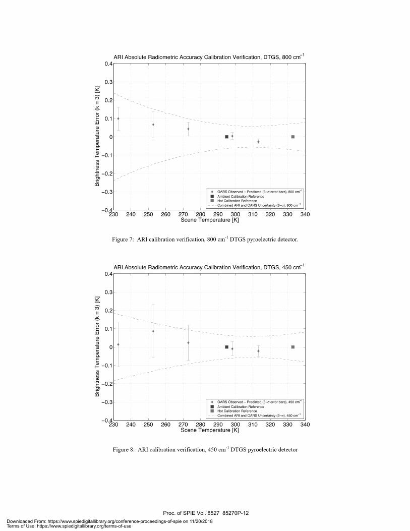
Figure 7: ARI calibration verification, 800 cm-1 DTGS pyroelectric detector.
Figure 8: ARI calibration verification, 450 cm-1 DTGS pyroelectric detector
230 240 250 260 270 280 290 300 310 320 330 340−0.4
−0.3
−0.2
−0.1
0
0.1
0.2
0.3
0.4
Scene Temperature [K]
Brig
htne
ss T
empe
ratu
re E
rror (
k =
3) [K
]
ARI Absolute Radiometric Accuracy Calibration Verification, DTGS, 800 cm−1
OARS Observed − Predicted (3−! error bars), 800 cm−1
Ambient Calibration ReferenceHot Calibration ReferenceCombined ARI and OARS Uncertainty (3−!), 800 cm−1
230 240 250 260 270 280 290 300 310 320 330 340−0.4
−0.3
−0.2
−0.1
0
0.1
0.2
0.3
0.4
Scene Temperature [K]
Brig
htne
ss T
empe
ratu
re E
rror (
k =
3) [K
]
ARI Absolute Radiometric Accuracy Calibration Verification, DTGS, 450 cm−1
OARS Observed − Predicted (3−! error bars), 450 cm−1
Ambient Calibration ReferenceHot Calibration ReferenceCombined ARI and OARS Uncertainty (3−!), 450 cm−1
Proc. of SPIE Vol. 8527 85270P-12Downloaded From: https://www.spiedigitallibrary.org/conference-proceedings-of-spie on 11/20/2018Terms of Use: https://www.spiedigitallibrary.org/terms-of-use

4. SUMMARY An excellent, low cost, climate benchmark mission has been defined, and the proposed IR measurement requirements are supported by excellent technical readiness. The UW-SSEC ARI and On-orbit Test and Verification (OTV) module has demonstrated the technology necessary to measure IR spectrally resolved radiances (3.3 – 50 µm) with ultra high accuracy (< 0.1 K, k = 3 brightness temperature at scene temperature) required for a benchmark climate mission such as the US National Research Council recommended Climate Absolute Radiance and Refractivity Observatory (CLARREO) [2] or that defined in the ASIC3 report [1]. The UW-SSEC ARI subsystems have been selected and developed to provide a system with a clear path to space.
REFERENCES
1. Ohring, George, et al. "Achieving satellite instrument calibration for climate change." Eos, Transactions American Geophysical Union 88.11 (2007): 136.
2. National Research Council (US). Committee on Earth Science, et al. Earth science and applications from space: national imperatives for the next decade and beyond. National Academy Press, 2007.
3. Anderson, J. G., et al. "Absolute, spectrally-resolved, thermal radiance: a benchmark for climate monitoring from space." Journal of Quantitative Spectroscopy and Radiative Transfer 85.3 (2004): 367-383.
4. Kirk-Davidoff, Daniel B., Richard M. Goody, and James G. Anderson. "Analysis of sampling errors for climate monitoring satellites." Journal of climate 18.6 (2005): 810-822.
5. Goody, Richard, James Anderson, and Gerald North. "Testing climate models: An approach." Bulletin-American Meteorological Society 79 (1998): 2541-2549.
6. Goody, Richard, and Robert Haskins. "Calibration of radiances from space." Journal of climate 11.4 (1998): 754-758.
7. Revercomb, Henry E., et al. "FTS calibration: Demonstrated absolute accuracy for IR remote sensing and future for monitoring climate." Fourier Transform Spectroscopy. Optical Society of America, 2005.
8. Revercomb, H. E., et al. “Spectrally Resolved IR Radiances for the CLARREO Climate Mission”, 2007 CALCON Technical Conference, (2007).
9. Best, F.A., et al. “On-orbit Absolute Temperature Calibration for CLARREO (NASA’s New Climate Mission)”, 2007 CALCON Technical Conference, (2007).
10. Dykema, John A., and James G. Anderson. "A methodology for obtaining on-orbit SI-traceable spectral radiance measurements in the thermal infrared." Metrologia 43.3 (2006): 287.
11. Best, Fred A., et al. "On-Orbit Absolute Radiance Standard for Future IR Remote Sensing Instruments." AGU Fall Meeting Abstracts. Vol. 1. 2010.
12. Pettersen, Claire. "On-Orbit Absolute Radiance Standard for Future IR Remote Sensing Instruments-Overview of Recent Technology Advancements." Fourier Transform Spectroscopy. Optical Society of America, 2011.
13. Best, F.A., et al. “On-orbit absolute radiance standard for future IR remote sensing instruments.” Earth Science Technology Forum 2011 (ESTF2011). NASA, Jet Propulsion Laboratory, 2011
14. Best, F. A., et al. "On-orbit Absolute Radiance Standard (OARS) for the next generation of IR remote sensing instruments," Proc. SPIE 8527, 23 (2012).
15. Gero, P. Jonathan, John A. Dykema, and James G. Anderson. "A quantum cascade laser-based reflectometer for on-orbit blackbody cavity monitoring." Journal of Atmospheric and Oceanic Technology 26.8 (2009): 1596-1604.
16. Gero, P. J., et al. "On-orbit absolute blackbody emissivity determination using the heated halo method," Proc. SPIE 7857, 78570L (2010).
17. Dykema, John, Mark Witinski, and James Anderson. "Testing Space-based Infrared Sensors for Systematic Errors." Fourier Transform Spectroscopy. Optical Society of America, 2011.
18. Gero, P. Jonathan, et al. "On-orbit absolute blackbody emissivity determination using the heated halo method." Metrologia 49.2 (2012): S1.
19. Gero, P. Jonathan,et al. “The heated halo for space-based blackbody emissivity measurement”, Proc. SPIE 8527, 25 (2012).
20. Taylor, Joe K., et al. "The University of Wisconsin Space Science and Engineering Center Absolute Radiance Interferometer (ARI)." Proceedings of SPIE. Vol. 7857. 2010.
Proc. of SPIE Vol. 8527 85270P-13Downloaded From: https://www.spiedigitallibrary.org/conference-proceedings-of-spie on 11/20/2018Terms of Use: https://www.spiedigitallibrary.org/terms-of-use

21. Taylor, J. K., et al. "A New Class of Advanced Accuracy Satellite Instrumentation (AASI) for the CLARREO Mission: Interferometer Test-bed Tradestudies and Selection." AGU Fall Meeting Abstracts. Vol. 1. 2009.
22. Taylor, J.K., et al. The University of Wisconsin Space Science and Engineering Center Absolute Radiance Interferometer (ARI). International Conference on New Developments and Applications in Optical Radiometry (NEWRAD), 11th. 2011
23. Taylor, Joe, et al. "The University of Wisconsin Space Science and Engineering Center Absolute Radiance Interferometer (ARI)." Fourier Transform Spectroscopy. Optical Society of America, 2011.
24. Best, F. A., et al. “GIFTS On-board Blackbody Calibration Subsystem.” NASA GIFTS EDU and Other FTS Instruments. 2006.
25. Best, Fred A., et al. "Performance verification of the Geosynchronous Imaging Fourier Transform Spectrometer (GIFTS) on-board blackbody calibration system." Proceedings of SPIE. Vol. 6405. 2006.
26. Revercomb, Henry E., et al. "Radiometric calibration of IR Fourier transform spectrometers: solution to a problem with the High-Resolution Interferometer Sounder." Applied Optics 27.15 (1988): 3210-3218.
27. BIPM, IEC, IFCC, ISO, & IUPAC. Guide to the Expression of Uncertainty in Measurement. International Organization for Standardization, Geneva. ISBN, 92-67
28. Best, F., et al. “Accurately calibrated airborne and ground-based Fourier Transform Spectrometers II: HIS and AERI calibration techniques, traceability, and testing.” Council for Optical Radiation Measurements (CORM) 1997 Annual Meeting. 1997.
29. Knuteson, R. O., et al. "Atmospheric emitted radiance interferometer. Part II: Instrument performance." Journal of Atmospheric and Oceanic Technology 21.12 (2004): 1777-1789.
30. Revercomb, H. E. “Techniques for Avoiding Phase and Non-linearity Errors in Radiometric Calibration: A Review of Experience with the Airborne HIS and Ground-based AERI.” Proceedings of the 5th International Workshop on Atmospheric Science from Space using FTS, 353-378.
31. Taylor, Joe K., et al. "Analysis of the CrIS Flight Model 1 Radiometric Linearity." Fourier Transform Spectroscopy. Optical Society of America, 2009.
32. Tobin, David C., et al. "Analysis of Cross-track Infrared Sounder (CrIS) Prelaunch Test Data." Fourier Transform Spectroscopy. Optical Society of America, 2005.
Proc. of SPIE Vol. 8527 85270P-14Downloaded From: https://www.spiedigitallibrary.org/conference-proceedings-of-spie on 11/20/2018Terms of Use: https://www.spiedigitallibrary.org/terms-of-use